

Page 1

OPERATION
MANUAL
770-00052 | REVISION A | 07.30.2017
Page 2

To download the most current user manual for the
Pilot and all other Freefly products, please visit
http://freeflysystems.com/software-manuals
@freeflysystems | #freeflyers
Page 3

REVISION HISTORY
REVISION DATE DESCRIPTION
A July 2017 Initial Manual Release
3| OPERATION MANUAL
Page 4

CONTENTS
3 Revision History
4 Contents
5 Terminology
6 OVERVIEW
7 Disclaimer and Warning
10 Limitations of Liability
11 Warranty
13 Introduction
14 Pilot Modules
21 System Diagrams
23 SETTING UP PILOT
24 Getting Started
25 Out Of The Box
39 USING PILOT
41 MIMIC User Interface
58 Using The Mobile App
61 Freefly Controller Ecosystem
67 TROUBLESHOOTING
70 APPENDIX
4| OPERATION MANUAL
Page 5

TERMINOLOGY
2.4 GHz An industrial, scientific, and medical (ISM) radio
band (2.4-2.5GHz) that is used for radio control.
BLE Bluetooth Low Energy (BLE) is a low power and
application friendly version of Bluetooth.
FIZ An acronym referring to a lens's Focus, Iris, and Zoom.
Function Side The side of the connector that interfaces with another connector.
GCU Gimbal Control Unit (GCU) refers to the MōVI's central
processor and housing, which is attached to the pan arm.
GPS Global Positioning System (GPS) is a satellite-based
navigation system made up of a network of 31 satellites
that can be used to determine global position.
INS An inertial navigation system (INS) is an electronic
device that measures and reports a body's specific
force, position, angular rate, and sometimes the
magnetic field, using a combination of accelerometers,
compasses, magnetometers, gyroscopes, and GPS.
LOS Loss of Signal (LOS) refers to a condition where radio
control inputs or telemetry are not present.
Module Pilot consists of various “modules” which represent standalone
components which can be added/removed to configure Pilot
RCP REDLINK® Command Protocol (RCP) is the unified
command protocol used for the RED EPIC and
SCARLET cameras, regardless of sensor type.
RX RX is an acronym for receive, receiver, or reception.
Solder Side This is the side of the connector where the
wires are soldered to the connector.
TX TX is an acronym for transmit or transmitter.
UART A Universal Asynchronous Receiver/Transmitter
(UART) is a block of circuitry responsible for
implementing serial communication.
5| OPERATION MANUAL
Page 6

Overview
OVERVIEW
6| OPERATION MANUAL
Page 7

DISCLAIMER AND WARNING
IMPORTANT - Please read this disclaimer and warning carefully and review the
Pilot Operation Manual prior to use. If you have any questions, please contact
support@freeflysystems.com prior to using Pilot Controller. You can review the
most current version of this Operation Manual at www.freeflysystems.com/
software-manuals.
By using Pilot Controller, you acknowledge that you have read, understand, and agree to this
disclaimer. You agree that you are solely responsible for your conduct while using Pilot Controller
and for any direct or indirect consequences that may result from its use.
Freefly Systems reserves the right to revise this Operation Manual and make changes from time
to time without obligation to notify any persons of such revisions or changes. In no event shall
Freefly Systems, its employees or authorized agents be liable for any damages or losses, direct
or indirect, arising from the use of any technical or operational information contained in this
document.
» Always check Pilot Controller, MōVI products and all Freefly hardware prior to operation.
» Always maintain awareness of your surroundings when operating Freefly products.
» It is your responsibility to perform a full system check prior to every use.
» It is your responsibility to learn how to safely operate Pilot Controller and MōVI products.
» Pilot Controller is a tuned system with custom components selected for each
application. Modification to, removal, or substitution of Pilot Controller components will
void the warranty.
» It is your responsibility to create shots that amaze the world.
BATTERIES AND CHARGING
The Pilot Controller includes MIMIC, which contains a non-removable internal battery. You must
read these safety instructions and warnings carefully before charging or using your MIMIC. Failure
to exercise caution while using MIMIC or failure to comply with the following warnings can result
in battery malfunction, electrical issues, excessive heat, fire, personal injury, and/or property
damage. For information specific to MōVI Batteries/Chargers please reference the applicable MōVI
manual.
BATTERY SAFETY AND WARNINGS
You must read these safety instructions and warnings carefully before charging or using Pilot
Controller. Improper use may result in damage to the batteries, severe personal injury, and even
fire.
» Do not leave the MIMIC and charger unattended during use.
» Stop using or charging the MIMIC immediately if the MIMIC appears damaged, starts to
7| OPERATION MANUAL
Page 8

balloon or swell, leaks, becomes deformed or gives off an odor, exceeds a temperature
of 140ºF (60ºC), or if anything else abnormal occurs. Disconnect the MIMIC (USB) and
observe in a safe area outside of any building or vehicle for at least 45 minutes, as a
damaged battery can experience a delayed chemical reaction that could possibly result
in fire.
» Never disassemble, modify, puncture, shock, crash, short circuit, and/or expose the
MIMIC to a flame. Leakage, smoke emission, ignition, explosion or fire can occur, which
may result in personal injury or property damage.
» Never allow MIMIC or Pilot Modules to come in contact with moisture at any time.
» Never charge or store MIMIC in extreme heat (40ºC) or cold (0ºC). Recommended
temperatures for storage are between 10º-26ºC. High temperatures may cause fire,
even with undamaged MIMICs.
» Never leave MIMIC or any Pilot Modules in an automobile or direct sunlight.
» In purchasing a Freefly product or system, the buyer agrees to bear all responsibilities
of the risks and not hold Freefly Systems, its owners and employees, its distributors,
and/or its retailers responsible for any accidents, injury to persons, and property
damage. If you do not agree to these conditions, please return Freefly product(s) to the
place of purchase in a new and unused condition.
All instructions and warnings must be followed exactly.
Mishandling of MIMIC and its internal battery can
result in fire. By handling, charging, or using the
included MIMIC internal battery , you assume all risks
CAUTION
associated with MIMIC. If you are not prepared to accept
complete liability for the purchase and/or use of the
batteries, you are advised to return them in new and
unused condition to the place of purchase immediately.
8| OPERATION MANUAL
Page 9

CHARGING PROCEDURE SAFETY AND WARNINGS
You must read these safety instructions and warnings carefully before charging your MIMIC.
» Freefly Systems is not responsible for any personal injury or property damage incurred
when using external power to power Freefly products.
» Never charge or use a MIMIC or Pilot Module that shows any damage or disfigurement
of any kind, as this may be a sign of internal damage. Any damage to the protective
cover or connector is also reason to discontinue use.
» Never charge a MIMIC unattended.
» Always inspect MIMIC and Pilot Modules before charging.
» Never charge near moisture, extreme temperatures, flammable or combustible
materials.
» Always monitor the temperature of the MIMIC while charging. If the MIMIC becomes
hot to the touch or begins to deform, discontinue charging immediately. Disconnect the
battery from the charger and observe it in a safe place for at least 45 minutes.
9| OPERATION MANUAL
Page 10

LIMITATIONS OF LIABILITY
IN NO EVENT SHALL FREEFLY SYSTEMS BE LIABLE TO THE BUYER FOR ANY INDIRECT,
CONSEQUENTIAL, PUNITIVE, INCIDENTAL, OR SPECIAL DAMAGES, OR ANY DAMAGES
WHATSOEVER RESULTING FROM THE USE OF PRODUCT OR FROM LOSS OF USE, DATA OR
PROFITS (HOWEVER CAUSED AND UNDER ANY THEORY OF LIABILITY), EVEN IF FREEFLY
HAS BEEN ADVISED OF THE POSSIBILITY OF SUCH DAMAGES. IN NO EVENT SHALL
FREEFLY’S LIABILITY FOR A PRODUCT (WHETHER ASSERTED AS A TORT CLAIM, A CONTRACT
CLAIM OR OTHERWISE) EXCEED THE AMOUNTS PAID TO FREEFLY FOR SUCH PRODUCT.
NOTWITHSTANDING ANYTHING HEREIN, IN NO EVENT SHALL FREEFLY’S LIABILITY FOR ALL
CLAIMS ARISING OUT OF OR RELATING TO THIS AGREEMENT EXCEED THE AMOUNTS PAID
BY BUYER TO FREEFLY FOR PRODUCT IN THE LAST TWELVE (12) MONTHS. IN NO EVENT WILL
FREEFLY OR ITS LICENSORS BE LIABLE FOR COSTS OF PROCUREMENT OF SUBSTITUTE
GOODS BY BUYER. IN NO EVENT WILL FREEFLY OR ITS LICENSORS BE LIABLE FOR DAMAGES
ARISING OUT OF ANY LATE DELIVERY. THE LIMITATIONS SET FORTH HEREIN SHALL APPLY
TO ALL LIABILITIES THAT MAY ARISE OUT OF THIRD-PARTY CLAIMS AGAINST BUYER. THESE
LIMITATIONS SHALL APPLY NOTWITHSTANDING ANY FAILURE OF ESSENTIAL PURPOSE OF ANY
LIMITED REMEDY. THE LIMITATION SET FORTH IN THIS SECTION SHALL APPLY WHERE THE
DAMAGES ARISE OUT OF OR RELATED TO THIS AGREEMENT.
Freefly shall not be liable for damages or injuries incurred directly or indirectly from the use of
Pilot Controller including, but not limited to, the following situations:
» Failure of operator to follow proper instructions and safety warnings found at www.
freeflysystems.com.
» Failure of the operator to understand and operate Pilot Controller within the operating
limitations described in this manual.
» Failure of the operator to follow on-board safety warnings while using Pilot Controller or
Freefly products.
» Failure of the operator to inspect Pilot Controller and its components prior to operation.
» Failure of the operator to properly maintain and/or service Pilot Controller through an
authorized Freefly Service Center with genuine Pilot Controller parts.
» Use of third-party products on Pilot Controller.
» Use of Pilot Controller in unsafe conditions, including but not limited to, bad or severe
weather, such as rain, wind, snow, lightning, dust storms, etc.
» Improper operation, misjudgment or risky behavior while using Pilot Controller or
Freefly products.
» Infringement of third party data, audio or video rights recorded when using Pilot
Controller or Freefly products.
10| OPERATION MANUAL
Page 11

WARRANTY
SPECIFICATIONS
Freefly warrants all products will be of good quality and workmanship and free from material
defects. Upon the expiration of the time periods below, all liabilities of Freefly will terminate. In
no event shall Freefly be liable for consequential damages. Freefly may use refurbished parts
for repairs or replacements. Certain products may be subject to a separate software license
agreement.
STANDARD WARRANTY
A Standard Warranty is granted to the original purchaser by Freefly for a period of one (1) year,
parts and labor. The Standard Warranty covers parts and labor charges for Product that has been
returned with shipment to an Authorized Service Center by the Buyer. Service or replacement
decisions are at the sole discretion of Freefly. Proof of purchase is required for warranty claims.
All warranty returns shall be done in accordance with Freefly’s warranty Return Merchandise
Authorization (“RMA”) policy. Any repaired or replaced Product shall be warranted as set forth in
this section for a period the greater of (a) the balance of the applicable warranty period relating
to such Product or (b) ninety (90) days after it is received by Buyer. Only the components that
were repaired or replaced will be eligible for the 90-day period as set forth above. The Standard
Warranty effective date is the date of “ex works” from Woodinville, Washington.
WARRANTY LIMITATIONS
All Freefly warranties do not cover (a) maintenance, repair or replacement necessitated by
loss or damage resulting from any cause other than normal use and operation of the Product
in accordance with Freefly’s specifications and owner’s manual, including but not limited to:
theft, exposure to weather conditions, operator negligence, misuse, abuse, improper electrical/
power supply; (b) alterations, modifications, or repairs by Buyer or unauthorized third parties; (c)
accident, disaster, improper handling or storage, drop, modification, opening sealed components,
use of third party accessories or acts of nature or any other peril originating from outside the
Product; (d) transportation damage, lack of or improper maintenance, defective batteries, battery
leakage; and (e) cosmetic damage or other non-operating parts. Removal or modification of sealed
components, including but not limited to, motors or electronics, voids any and all warranties.
Breaking the seal on any sealed components, including but not limited to motors or electronics,
is prohibited and voids any and all warranties unless otherwise approved by Freefly. Any parts
replaced by Freefly during warranty repair are the property of Freefly and will not be returned to
Buyer. Freefly may use refurbished parts for repairs or replacements.
Freefly products are compatible with Freefly software, Freefly parts and Freefly products only. Use
of any software, parts, or products, other than Freefly or Freefly approved software, parts, and
products, which plug into or directly affect the function or performance of Freefly products voids
any and all warranties.
11| OPERATION MANUAL
Page 12

LIMITATION OF LIABILITY
EXCEPT AS SPECIFICALLY SET FORTH ABOVE, FREEFLY AND ITS LICENSORS MAKE NO
WARRANTIES, CONDITIONS, REPRESENTATIONS OR TERMS, EXPRESSED OR IMPLIED,
WHETHER BY STATUTE, COMMON LAW, CUSTOM, USAGE OR OTHERWISE AS TO THE
FREEFLY PRODUCT OR ANY COMPONENT THEREOF, INCLUDING BUT NOT LIMITED TO NONINFRINGEMENT OF THIRD PARTY RIGHTS, INTEGRATION, MERCHANTABILITY, SATISFACTORY
QUALITY, OR FITNESS FOR ANY PARTICULAR PURPOSE. FREEFLY AND ITS LICENSORS DO NOT
WARRANT THE PERFORMANCE OR RESULT OF THE FREEFLY PRODUCT. THE SOLE REMEDY
UNDER THIS WARRANTY SHALL BE THE REPAIR OR REPLACEMENT FOR DEFECTIVE PARTS
AS STATED ABOVE. THIS WARRANTY IS THE SOLE WARRANTY GIVEN BY FREEFLY AND IS IN
LIEU OF ANY OTHER WARRANTIES EITHER EXPRESS OR IMPLIED. THIS WARRANTY EXTENDS
TO THE BUYER AND IS NON-TRANSFERABLE TO OTHER THIRD PARTIES. FREEFLY SHALL NOT
BE LIABLE FOR SPECIAL, INDIRECT, INCIDENTAL OR CONSEQUENTIAL DAMAGES, LOSS OF
PROFITS OR PRODUCTION OR COMMERCIAL LOSS IN ANY WAY, REGARDLESS OF WHETHER
SUCH CLAIM IS BROUGHT IN CONTRACT, WARRANTY, TORT, NEGLIGENCE, STRICT LIABILITY OR
ANY OTHER THEORY OF LIABILITY, EVEN IF FREEFLY HAS BEEN ADVISED OF THE POSSIBILITY
OF SUCH DAMAGES. IN NO EVENT SHALL THE LIABILITY OF FREEFLY EXCEED THE INDIVIDUAL
PRICE OF THE PRODUCT ON WHICH LIABILITY IS ASSERTED.
THIRD PARTY WARRANTY
Freefly does not honor warranty agreements extended by third parties. Only warranty agreements
granted by Freefly will be honored by Freefly.
NON-WARRANTY REPAIR
Product that no longer qualifies for Warranty Repair may be sent to an Authorized Freefly
Service Center subject to an evaluation fee. Freefly will provide a quotation for the repair of the
Product. The Customer is responsible for all costs associated with such refurbishment, such as
troubleshooting, diagnosis, repair, test, calibration, storage, and shipping costs. The evaluation
fee will be applied to the cost of the refurbishment if the cost of the refurbishment is greater than
the evaluation fee. Any repaired or replaced product shall be warranted for ninety (90) days after
it is received by Buyer. Only the components that were repaired or replaced will be eligible for the
90-day period. Any parts replaced by Freefly during non-warranty repair are the property of Freefly
and will not be returned to Buyer. Freefly may use refurbished parts for non-warranty repair.
LAW GOVERNING
These terms are governed by Washington State law (without regard to conflict of law principles or
the United Nations Convention on Contracts for the International Sale of Goods.) Freefly reserves
the right to change or modify this warranty at any time without notice. For up-to-date warranty
information, visit www.freeflysystems.com.
12| OPERATION MANUAL
Page 13

INTRODUCTION
The Freefly Pilot 3-Axis Focus/Iris/Zoom Controller is the latest addition to
Freefly’s expansive product offering, bringing you precise control over Focus/
Iris/Zoom, MōVI pointing and MōVI settings wirelessly. By combining industry
standard inputs for Focus/Iris/Zoom controls such as a 2-axis force joystick,
an adjustable Focus knob damping and Freefly’s patented MIMIC technology,
the Pilot provides filmmakers direct and intuitive control of the camera and
gimbal. In addition to its technology, the Pilot offers a compact, modular
design which accommodates a wide variety of setups. Whether using the Pilot
as a single operator or multiple, the Pilot can adapt. With the introduction of
Pilot into the Freefly ecosystem, the Pilot works seamlessly with other MIMIC
and MōVI Controllers.
This manual will provide information on how to setup, bind, and use your Pilot
Controller. It will also provide more examples into how Pilot can be used in
single or multi-operator modes as well as a few scenarios to help illustrate
this.
WARNINGS, CAUTIONS AND NOTES
Throughout the manual, warnings, cautions and notes are used to highlight various important
procedures. These are defined as follows:
WARNING
Warnings are used to highlight
procedures which, if not strictly
observed, may result in personal
injury or loss of life.
CAUTION
Cautions are used to highlight
procedures which, if not
strictly observed, may cause
damage to equipment.
NOTE
Notes are used to highlight
specific operating conditions
or steps of a procedure.
13| OPERATION MANUAL
Page 14
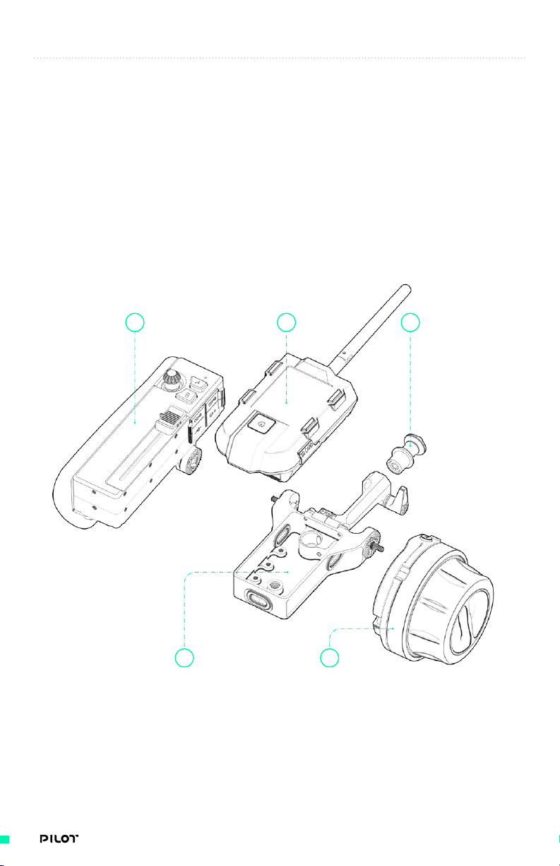
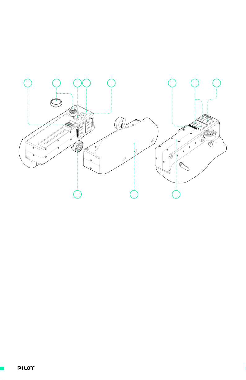
PILOT MODULES
OVERVIEW
The Pilot 3-Axis FIZ Controller is a compact, modular handheld controller providing filmmakers
with ultimate flexibility of setups. Each Pilot Module has been designed and customized with
specific functionality in mind, but can be easily reconfigured to support a wide variety of lens,
gimbal and camera controls.
Freefly’s MIMIC is at the center of the system, providing power to each Module and acting as the
primary user interface to quickly navigate through display options. Any Freefly MIMIC can be used
to work with your Pilot, just be sure to download v1.3 firmware or later onto your MIMIC (see
“Using Your Pilot” for more details on how and where to download). This section is aimed at
familiarizing you with each Module and how it is used within the Pilot 3-Axis F/IZ Controller.
1 2
1. Pilot Iris/Zoom Module
2. MIMIC
3. Pilot Backbone
4. 13mm Quick Release Plug
5. Pilot Focus Module
4
3
5
14| OPERATION MANUAL
Page 15
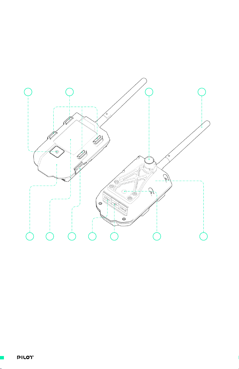
MIMIC
MIMIC has re-shaped the way people capture movement by providing long range bidirectional
control of MōVI orientation, settings, camera controls, and real time telemetry. Pilot leverages this
technology and expands its features to provide control of FIZ and P/T/R and additional camera
controls. Your MIMIC will come equipped with a quick release mount (13mm) rigidly attached to
the bottom and a ¼”-20 to accommodate additional mounting options. All MIMIC’s with version 1.3
firmware are compatible with Pilot Modules.
1 2 3
VIEW 1
4 5
1. On/Off Button
2. 4 Display Button
3. 2.4Ghz Antenna (long range wireless)
4. COM1 (UART), COM2 (UART)
5. USB C
6. Quick Release Mount
6
VIEW 2
78 91011
7. 1/4 - 20
8. SD Card Slot
9. Integrated Battery with up to 6 Hour
Run-Time
10. Integrated LCD
11. BLE Connectivity
15| OPERATION MANUAL
Page 16
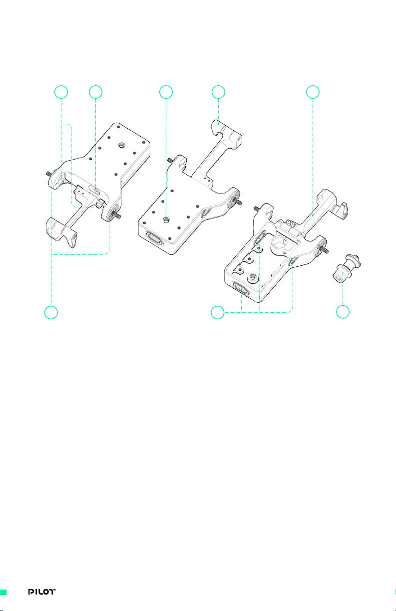
PILOT BACKBONE
The Pilot Backbone features a quick release mechanism to insert/remove your MIMIC, Freefly
rosettes to mount modules and a monitor mount with friction hinge mechanism.
2
1. (2x) 20mm Rosettes
2. (2x) M4 x 16 Socket Head Cap Screw
3. (1x) M4 Quick Release Lever
4. (1x) 13mm Monitor Mount/Integrated
Friction Hinge
5. M3 Integrated Quick Release Clamp
5 8
VIEW 1
3
VIEW 2
71
6. (1x) 13mm Quick Release Plug
7. (3x) Rubber Gaskets
8. Mounting Options
• M3 x 16 bolt pattern
• 1/4”-20
4
VIEW 3
6
16| OPERATION MANUAL
Page 17
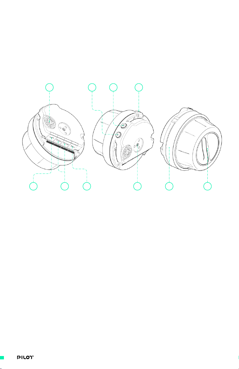
PILOT FOCUS MODULE
Smooth, precise Focus/Iris/Zoom control with adjustable viscous damping. The Pilot Focus Module
features an ergonomic soft-grip knob and a rotary dial to vary stiffness, a removable marking ring,
status LED, indicator dial, 20mm rosette and A/B buttons. This Module can be connected through
COM1 or COM2 to your MIMIC.
VIEW 1 VIEW 2 VIEW 3
5 6
1. A Button
2. B Button
3. (1x) 20mm Rosette
4. COM1 (UART), COM2 (UART)
5. USB C
6. CANbus (Microfit 4-pin)- for
expandability
7. Status LED
1 23
7
8 9104
8. Removable Marking Ring
9. Adjustable Stiffness Dial
10. Mounting Options
• Rosettes attached with (3x) M3 x 8
flat head cap screws
• (2x) Rosette mount options for M4,
spaced 25.55mm apart (center to
center)
17| OPERATION MANUAL
Page 18
PILOT IRIS/ZOOM MODULE
The Pilot Iris/Zoom Module can be mapped to Focus/Iris/Zoom as well as Pan/Tilt/Roll functions.
This Module features an industry standard precision 2-Axis force joystick, linear slide
potentiometer, removable walnut handle, 20mm rosette mount and A/B buttons, and an extra
(removable) joystick knob. The Pilot Iris/Zoom Module can be connected through COM1 or COM2 to
your MIMIC.
10
VIEW 1
3
1. A Button
2. B Button
3. (1x) 20mm Rosette Mount
4. COM1 (UART), COM2 (UART)
5. USB C
6. CANbus (Microfit 4-pin)- for
expandability
7. Status LED
8. Slide Potentiometer (linear slider)
12
VIEW 2
45 678
VIEW 3
9
9. Removable Walnut Handle
10. (2x) Force Joystick
• Fighter Pilot
• Thumb Pad
11. Mounting Options
• M3 x 16 Bolt Pattern
• M3 x 8 or M3 x 16 Bolt Pattern on
Bottom Surface
11
18| OPERATION MANUAL
Page 19
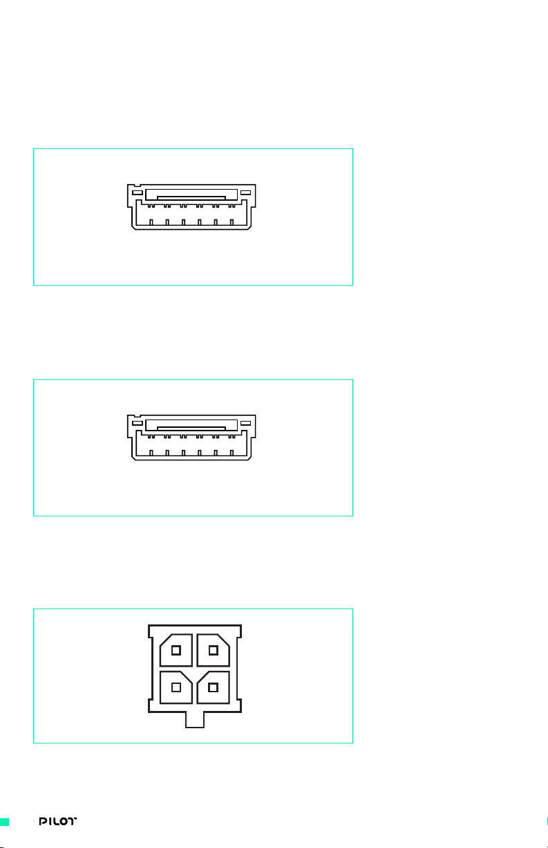
I/O CONNECTOR PINOUTS
All connector pinouts are shown looking into the function side of the connectors on the MIMIC and
Pilot Modules, unless otherwise noted.
CONNECTOR: COM 1
TYPE: JST GH 6-PIN
1. GND
2. +5V
3. UARTn_TX
21 3 4 5 6
CONNECTOR: COM 2
TYPE: JST GH 6-PIN
21 3 4 5 6
4. UARTn_RX
5. UARTn_CTS
6. UARTn_RTS
1. GND
2. +5V
3. UARTn_TX
4. UARTn_RX
5. UARTn_CTS
6. UARTn_RTS
CONNECTOR: CAN (CANBUS)
TYPE: MOLEX MICROFIT RA 4 PIN
3 4
21
1. GND
2. +V Ba
3. CAN H
4. CAN L
19| OPERATION MANUAL
Page 20

CONNECTOR: USB PORT
TYPE: USB TYPE C DRP (SOURCE AND SINK 5V)
20| OPERATION MANUAL
Page 21
SYSTEM DIAGRAMS
PILOT + MōVI
PILOT
Gimbal Control
Unit
Tilt Stage
Unit
Focus
Motor
Pan Motor
Iris
Motor
Roll Motor Tilt Motor
Zoom
Motor
RED Camera
Control
21| OPERATION MANUAL
Page 22
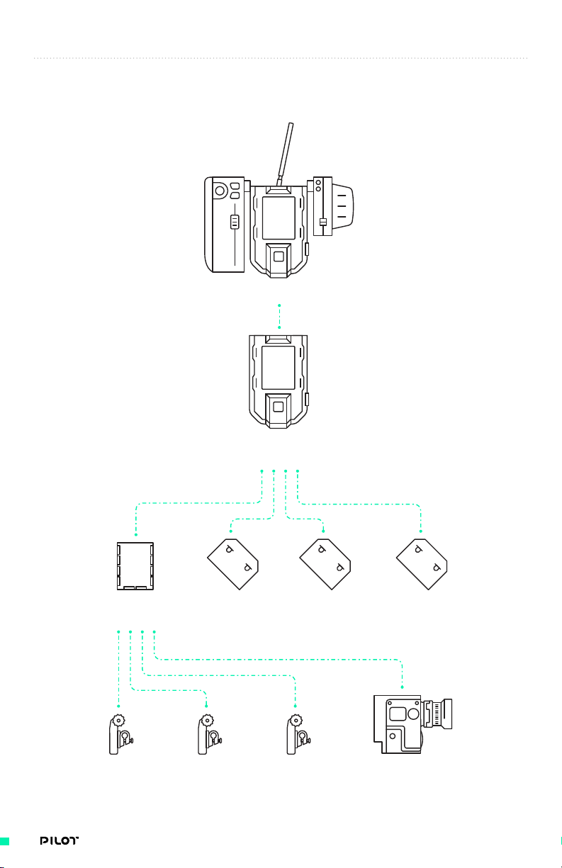
MIMIC INPUT PATHS
Illustration of available inputs to MIMIC.
Gestural
PILOT
Iris/Zoom Module
API
PILOT
Focus Module
MIMIC
Bush Pilot
Gamepad
22| OPERATION MANUAL
Page 23

Setting Up Pilot
SETTING UP
PILOT
23| OPERATION MANUAL
Page 24
GETTING STARTED
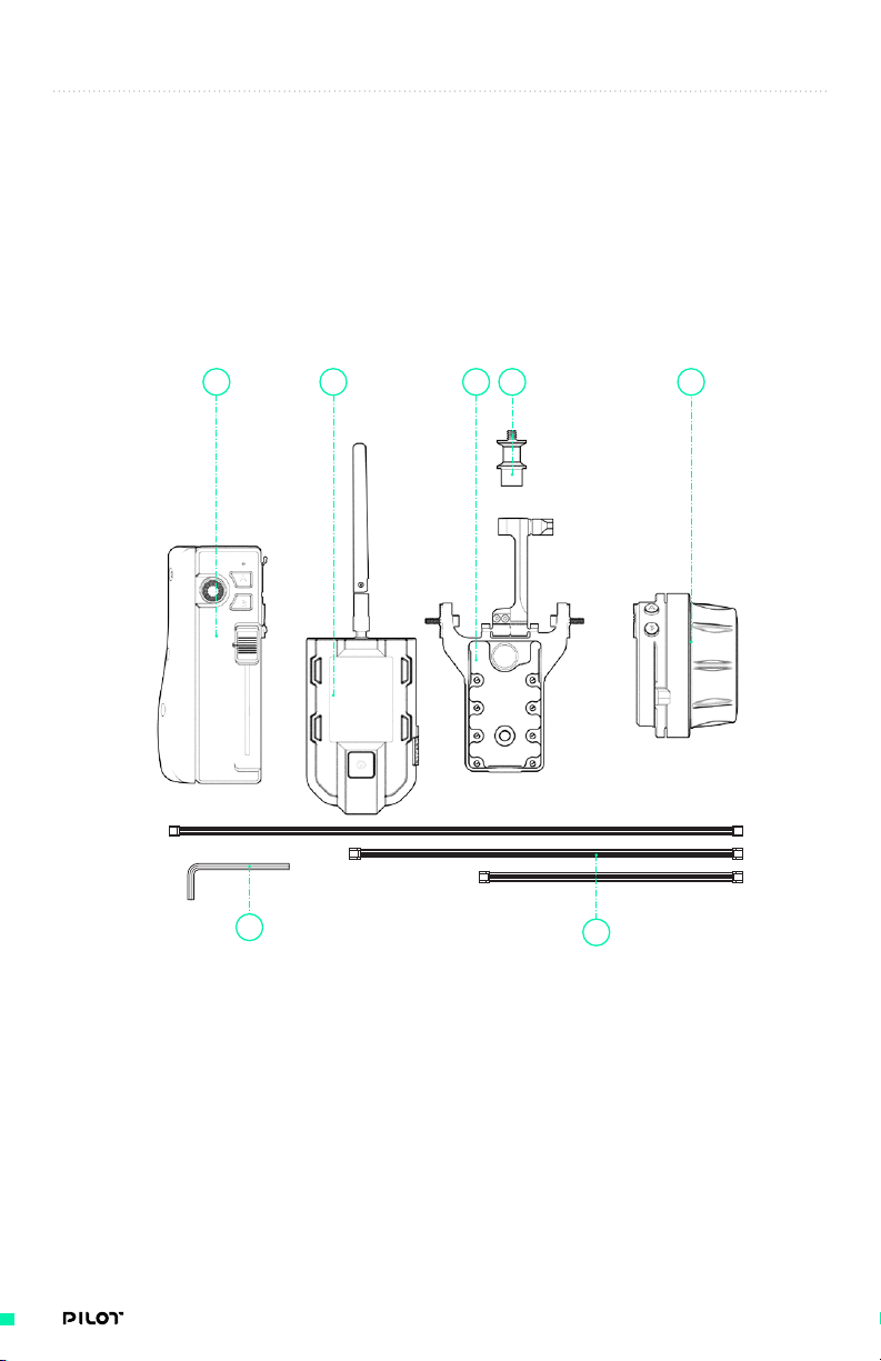
When your Pilot 3-Axis FIZ Controller arrives it will be securely packed along
with other contents shown below. This section will guide you through setup,
from out of the box to setting up with your MōVI system.
PACKAGE CONTENTS
PILOT 3-AXIS FIZ CONTROLLER
1 234 5
6
1. Pilot Iris/Zoom Module
2. Pilot Focus Module
3. Pilot Backbone
4. MIMIC + 13mm Quick Release Mount
5. Quick Release Plug 13mm
6. L-Key (Hex Key)
7
7. Cables
a. (4x) Pilot COM to COM cable - 200mm
b. (2x) Pilot COM to COM cable - 300mm
c. (2x) Pilot COM to COM cable - 500mm
d. (1x) USB 2.0 Type C to Micro B
e. (1x) USB Type C to Type A Cable- 1m
f. (1x) Jumper Reset Mimic Pro
24| OPERATION MANUAL
Page 25
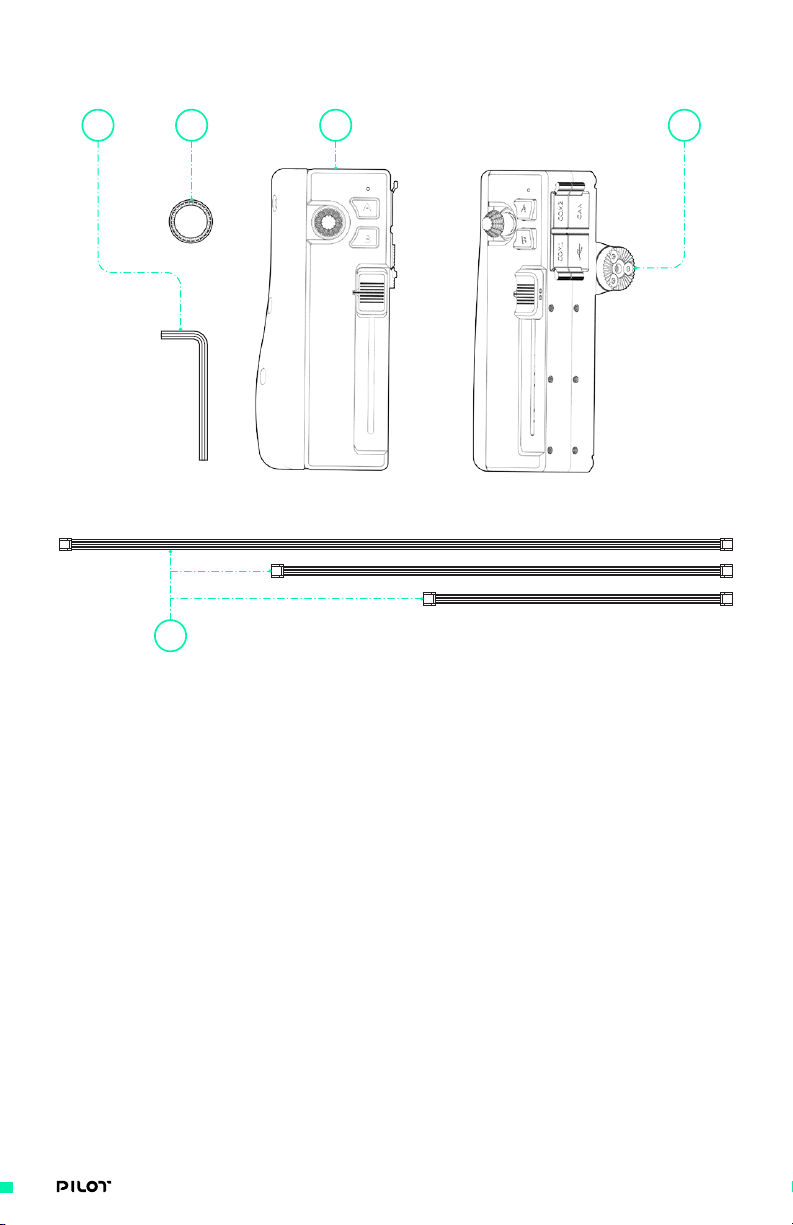
PILOT IRIS/ZOOM MODULE
4
5
1. Pilot Iris/Zoom Module
2. Extra joystick knob
3. Rosette Mount
4. L-Key (Hex Tool)
12 3
VIEW 1 VIEW 2
5. Cables
a. (2x) Pilot COM to COM cable - 200mm
b. (2x) Pilot COM to COM cable - 300mm
c. (2x) Pilot COM to COM cable - 500mm
25| OPERATION MANUAL
Page 26

PILOT FOCUS MODULE
1 2
1. Pilot Focus Module
2. Marking Ring
3. Cables
a. (2x) Pilot COM to COM cable - 200mm
b. (2x) Pilot COM to COM cable - 300mm
c. (2x) Pilot COM to COM cable - 500mm
VIEW 1
VIEW 2
3
26| OPERATION MANUAL
Page 27
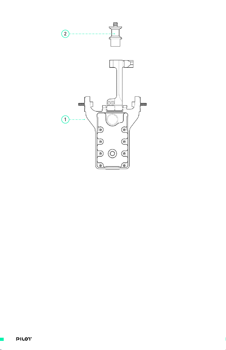
PILOT BACKBONE
2
1
1. Pilot Backbone
2. Quick Release Plug 13mm
ADDITIONAL ACCESSORIES
25mm Tube to Rosette Adapter
1.
2. Offset 25mm Tube to Rosette Adapter
3. 30mm Tube to Rosette Adapter
4. Offset 30mm Tube to Rosette Adapter
5. Pilot Marking Ring
6. Rosette Mount
7. Dual 13mm Quick Release Mount
These accessories are not included in any of the above but can be ordered separately to be used
with Pilot Controller.
27| OPERATION MANUAL
Page 28

OUT OF THE BOX
When your Pilot 3-Axis FIZ Controller arrives, it will be fully assembled with
all cables routed and secured to MIMIC and respective Modules. All inputs
will be mapped to factory default configuration, but can be customized to
control various axes. This section will serve as a quick start guide, walking you
through some of the basics such as starting with out of the box instructions,
firmware updates, binding to MōVI and brief instructions on setting up FIZ
motors.
BASIC SETUP
» Items Needed
» M4 Hex Driver
» M3 Hex Driver
» ¼” Hex Driver
28| OPERATION MANUAL
Page 29

OUT OF THE BOX
WAKE MIMIC FROM TRAVEL MODE
1. To wake your MIMIC from travel mode simply plug it into a 5V power source and push the
‘On’ button. If your MIMIC has already been taken out of travel mode continue to step 2.
5V
2. Turn on the MIMIC by pushing the Power button. Use the
display controls to move to the Radio Screen.
29| OPERATION MANUAL
Page 30

UPDATING MIMIC + MōVI
The MIMIC will come with the latest software already installed. The MōVI will
require the latest firmware (v1.3 or later) to be installed for Pilot functionality
to be enabled. To update firmware on each Pilot Module, please refer to
“Appendix- Pilot Module Firmware Updates” for more information.
PLEASE REFER TO THE MōVI PRO MANUAL FOR INSTRUCTIONS ON UPDATING YOUR Mō VI PRO.
BINDING MIMIC TO MōVI
MIMIC has been packed with functionality to support Pilot and integrate seamlessly within the
Freefly ecosystem. The top level screens enable efficient navigation of frequent interactions, giving
you control of Focus/Iris/Zoom or gimbal (Pan/Tilt/Roll). Multi-controller (two or more operators)
modes are also possible with Pilot- for more information reference “Using Your Pilot- Freefly
Controller Ecosystem”.
1. Select “Select Channel” and choose the channel you wish to
use to pair the MIMIC with your MōVI Pro/MōVI XL.
2. Turn on the MōVI and proceed to the Radio Screen. Use “Select Channel” to set the MōVI
to the same channel as the MIMIC. Press the Bind button on the MōVI; a progress bar will
appear showing the amount of time remaining to pair the device to a MIMIC.
30| OPERATION MANUAL
Page 31

3. Press the Bind button on the MIMIC within 5 seconds of pressing the Bind button on the
MōVI Pro/MōVI XL. The devices will pair automatically.
MIMIC uses a very powerful wireless transmitter to
control a MōVI; when this transmitter is in close
proximity (less than 5–10ft.) to its receiver, the
NOTE
receiver can be oversaturated with input causing
unwanted movements or binding issues. This is
normal behavior for power wireless transmitters.
NOTE
Priority must be set to “1” on MIMIC Radio screen for
successful binding to MōVI. If binding multiple MIMICs
to the same MōVI, each MIMIC must be bound separately
with Priority set to “1.” In other words, bind first
MIMIC and turn off, then bind a second MIMIC (with
priority set to 1) to MōVI. Once both have been bound
to MōVI, one of the MIMIC’s can now be set to Priority
“2” for system to function properly. For more specifics
on Priority and Multi-controller modes, see section
“Using Your Pilot- Multiple Controller Priorities.”
31| OPERATION MANUAL
Page 32

DEFAULT SETUPS/CONTROLS
MIMIC and Pilot Modules can be mapped (configured) through the MIMIC user interface to control
a variety of outputs/functions. Refer to the "Primary Control" column in the chart below, for
default axes configurations.
AXIS PRIMARY
CONTROL
Pan MIMIC Joystick Focus Knob Yes
Tilt MIMIC Joystick Focus Knob Yes
Roll MIMIC Joystick Focus Knob Yes
Focus Focus Knob Joystick Slider Yes
Iris Slider Joystick Focus Knob Yes
Zoom Joystick Slider Focus Knob Yes
SECONDARY
CONTROL
AUX CONTROL GESTURAL
CONTROL
DEFAULT SETUPS/INPUTS
As indicated above, a variety of user inputs can be mapped to each axis. This table summarizes
each Pilot Module inputs and their respective default mapping. For more information on specific
input devices and respective mapping options, reference “MIMIC Input Configuration” in Using
Your Pilot section.
If it is desirable to reset your MIMIC to defaults, this can be loaded from Mobile Apps. Go to
Monitor>Open Terminal>Default Configuration.
A “A” button toggles record start/stop
PILOT IRIS/ZOOM MODULE
PILOT FOCUS MODULE
B “B” button locks/unlocks Iris and Zoom on MIMIC.
Joystick Zoom for Joystick Y, Defer for Joystick X
Slider Iris
A Directly toggle through Pilot Focus Module
mapping between Defer, Focus, Iris and Zoom,
without the need of going to Inputs screen
B Used to set digital marks for the active axis
for the Pilot Focus Module while at the FIZ
Main screen. Up to 10 marks can be added. Press
and hold for 3 seconds to clear all marks.
Knob Focus
32| OPERATION MANUAL
Page 33
PILOT ADJUSTMENTS
Pilot gives you the ability to fine tune your setup. Whether using as a full FIZ controller or split
between FIZ and gimbal, you are able to adjust, add or remove Modules as desired.
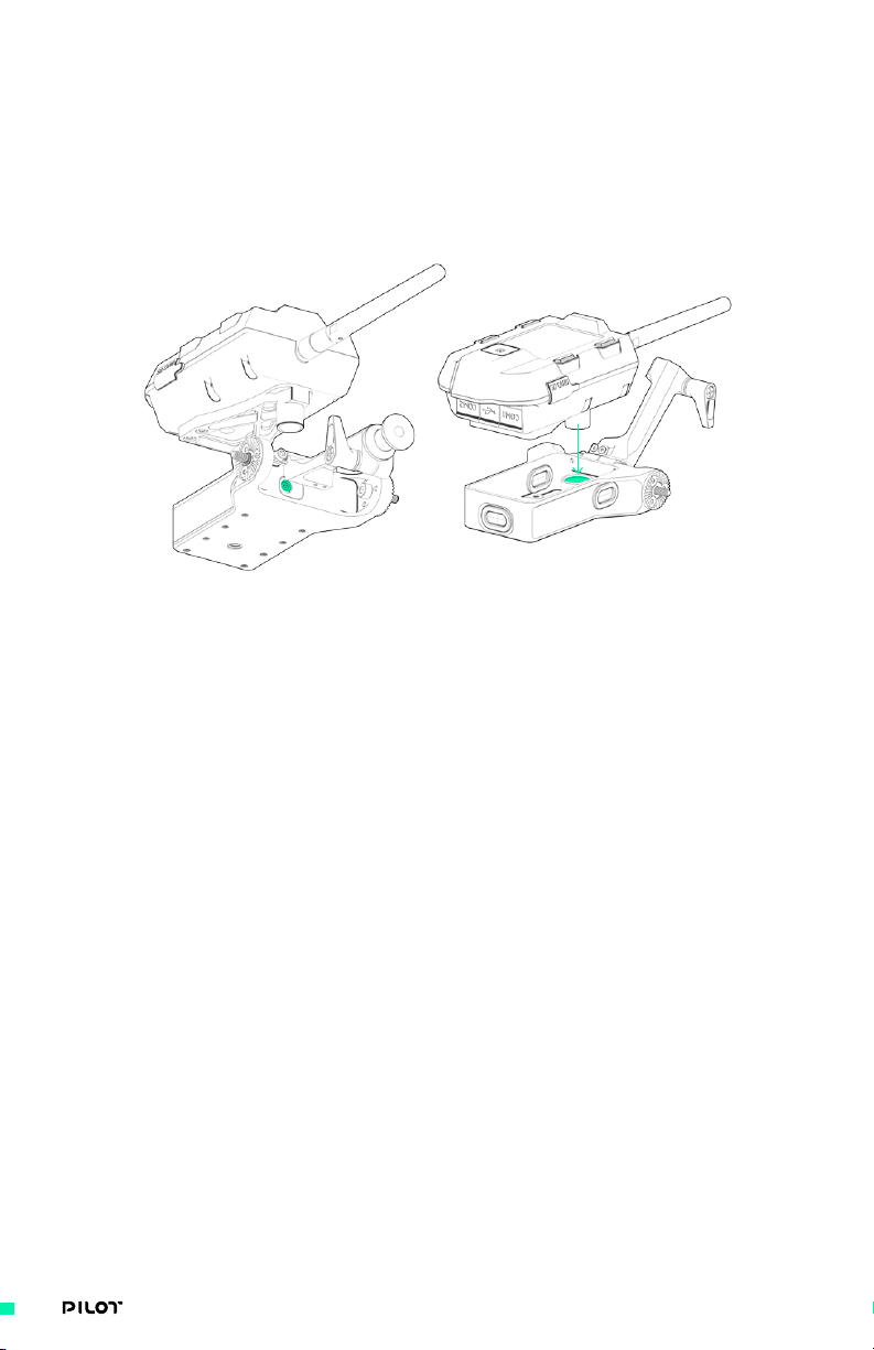
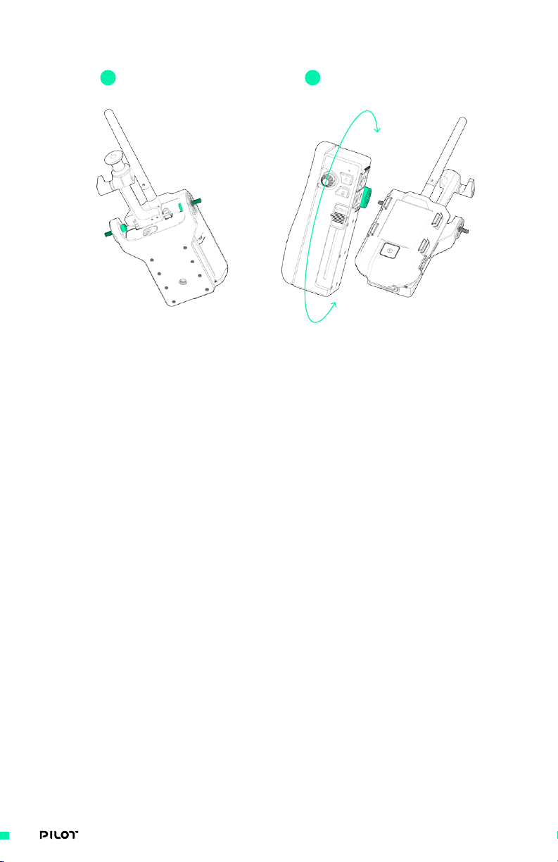
ATTACHING MIMIC TO PILOT BACKBONE
VIEW 1 VIEW 2
1. Using an M3 hex driver, tighten or loosen the integrated quick release
clamp and drop in MIMIC into 13mm pocket in Pilot Backbone
The MIMIC quick release mount is compatible with all Freefly 13mm quick release accessories
33| OPERATION MANUAL
Page 34
ADJUSTING ANGLE OF PILOT MODULES
1 2
1. Using an M4 hex driver, loosen the M4x16 bolt on either side of the Pilot Backbone
It is not necessary to fully remove bolt
2. Rotate Module to desired angle and re-tighten M4x16 bolt
Be sure 20mm rosettes are fully seated while tightening M4 bolt
34| OPERATION MANUAL
Page 35

ADJUSTING VERTICAL POSITION OF PILOT MODULES
1 2
1. The Focus Module has 2 discrete positions for mounting the
included 20mm rosette, spaced 25.5mm apart.
2. The Iris/Zoom Module includes provisions for M3 x 8 or M3 x 16
bolt pattern mounting of the included Rosette mount.
35| OPERATION MANUAL
Page 36
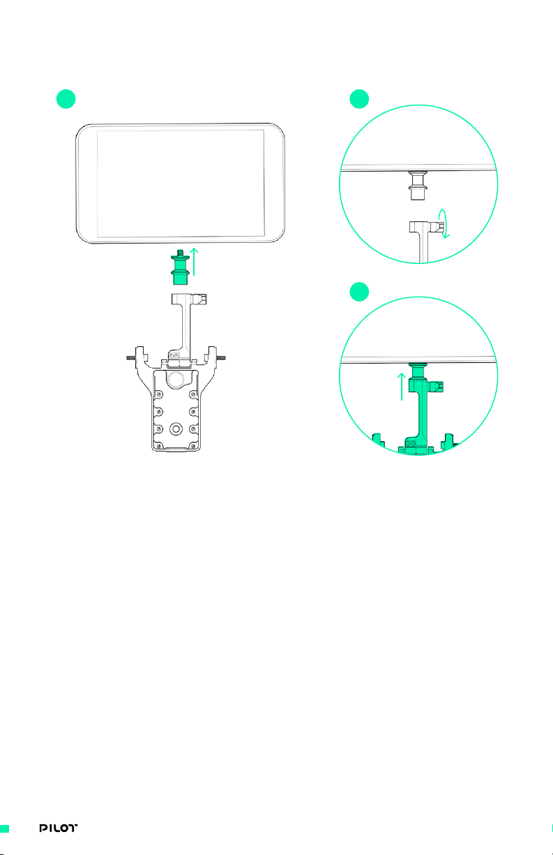
ADJUSTING A MONITOR TO PILOT BACKBONE
1 2
3
1. Using the provided 13mm Quick Release Plug, attach to a monitor with ¼”-20 hex
2. Loosen the M4 Quick Release Lever on the Integrated monitor mount
3. Insert the 13mm Quick Release Plug, attached to monitor,
and secure by tightening M4 Quick Release Lever
36| OPERATION MANUAL
Page 37
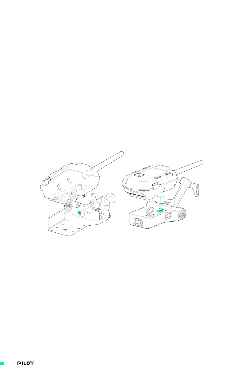
CONNECTING MIMIC TO MODULES
The Pilot 3-Axis FIZ Controller will already have connections made between the MIMIC and
Module(s). In case it is necessary to re-attach or remove cables:
1. Plug in UART cable into COM1 or COM2 port on Pilot Module
2. Plug other UART cable end to either COM1 or COM2 port on MIMIC
3. You should see Pilot Module LED startup sequence: One
long (half second) and two shorter blinks.
WIRE ROUTING
Cables to connect your MIMIC to each Module will arrive fully installed with the Pilot 3-Axis FIZ
Controller. Cables can easily be accessed or re-routed by removing the MIMIC from the Pilot
Backbone using an M3 hex driver to loosen the quick release clamp feature as shown above under
"Attaching MIMIC to Pilot Backbone."
VIEW 1 VIEW 2
37| OPERATION MANUAL
Page 38
PLEASE REFER TO THE MōVI PRO MANUAL FOR FULL INSTRUCTIONS ON SETTING UP FIZ CONTROL
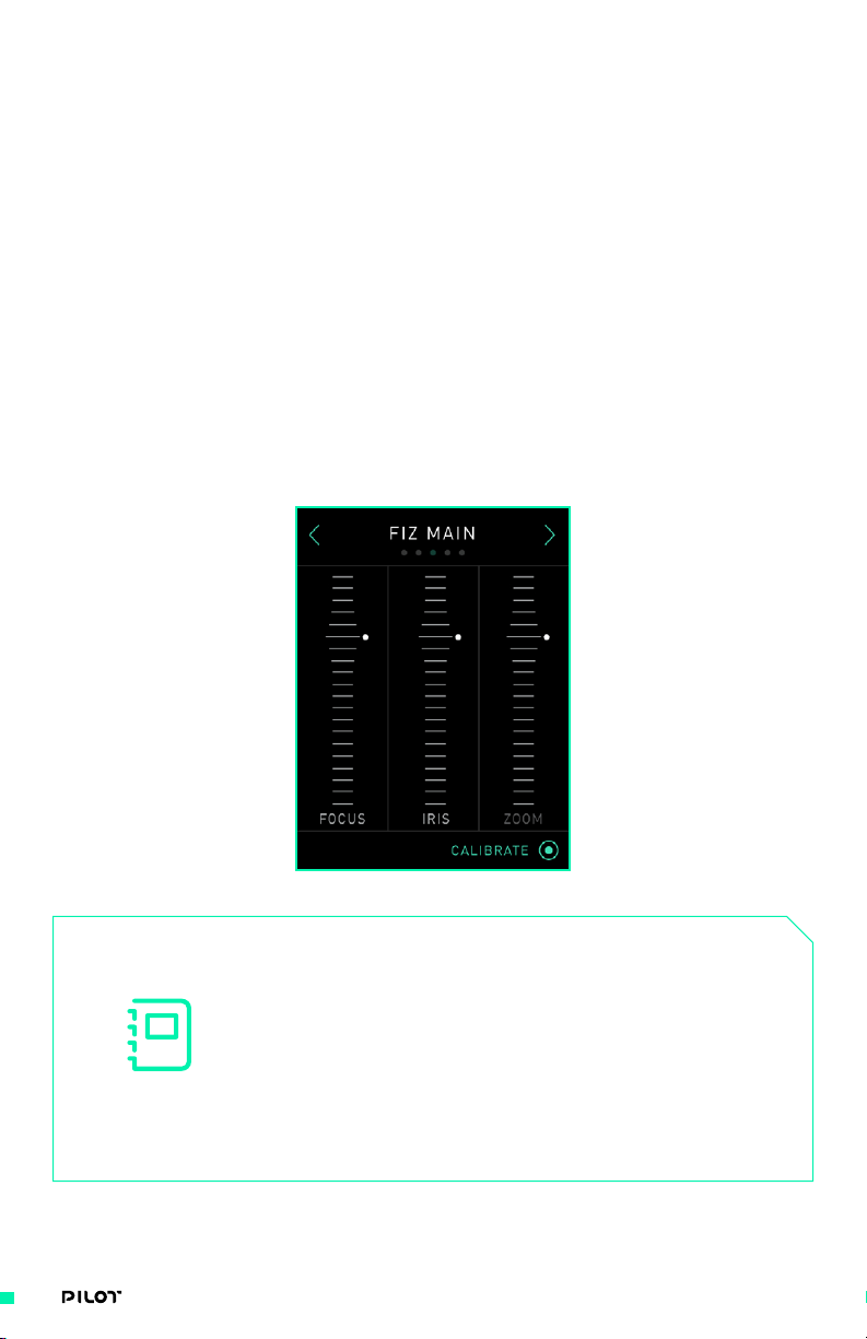
AUTO-CALIBRATING YOUR FIZ MOTORS
Be sure to check that all lens motors, rails, hardware and adjustments have been properly
verified. If anything is loose or misaligned, auto-calibration will not work properly. The FIZ motor
model needs to be configured prior to calibrating.
1. Navigate to FIZ Main Screen on MIMIC UI.
2. Select “Calibrate” by pressing lower right display button
to begin auto-calibration of all FIZ axes.
FIZ MAIN SCREEN
This screen displays the current status and position of focus, iris, and zoom axes, and allows users
to auto calibrate all lens motors simultaneously. Digital marks set by the Pilot Focus Module are
overlaid on its mapped axis.
NOTE
FIZ motors must have proper settings before calibration,
otherwise they may be damaged. Lenses with electronic
rings or without hard stops must be calibrated
manually. See FIZ Axis Screen, page 44, for more
information on manual calibration. During automatic
calibration, all motors rotate continuously until their
torque limit is hit, setting their maximum limit,
then rotated backwards to set their minimum limit.
38| OPERATION MANUAL
Page 39

USING PILOT
39| OPERATION MANUAL
Page 40

INTRO
With MIMIC powering the Pilot Modules, an integrated display guides you
through each of the top level screens for quick access to frequent controls and
options. Coupled with a mobile app that can assume complete control over the
MōVI settings, you can adjust tuning values, FIZ settings, and switch modes on
the fly. The following section walks through how to use the MIMIC with Pilot
Modules and how to be used either on their own or with other controllers.
40| OPERATION MANUAL
Page 41
MIMIC USER INTERFACE
The Pilot 3-Axis FIZ Controller relies on MIMIC technology as the central
user interface. The MIMIC is equipped with an integrated display and
navigation system which allows a user to check the system status, make quick
adjustments to FIZ controls, MōVI tuning, radio options, and more.
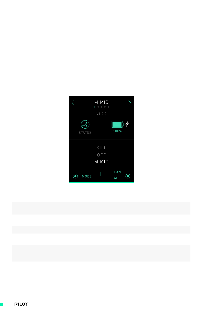
MIMIC SCREEN
This screen displays the MIMIC’s battery levels and system details including device status and
device mode.
OPTIONS DESCRIPTION
1. Status Icon Displays whether the MIMIC is
booting or has initialized.
2. Internal Battery Power (%) Displays the voltage remaining in the
internal MIMIC battery as a percentage.
3. Next Screen Button Takes users to the next screen.
4. Mode Toggles between the three
displayed MIMIC modes.
5. Pan Adjust Allows users to change the MIMIC pan
orientation in reference to the connected
MōVI while button is depressed.
41| OPERATION MANUAL
Page 42

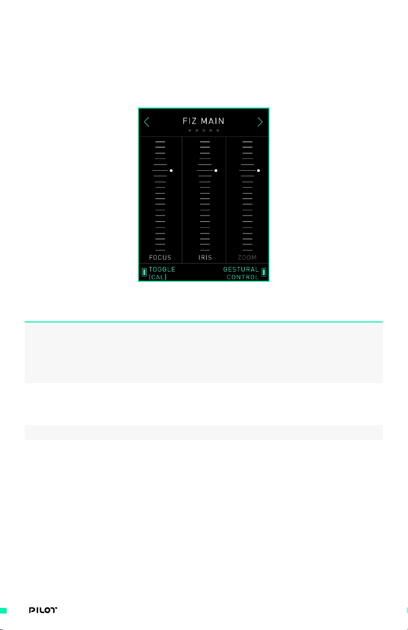
FIZ MAIN SCREEN
This screen displays the current status and position of Focus, Iris, and Zoom axes. With both Pilot
Modules connected, you will see all 3 axes highlighted on screen with outputs displayed as you
toggle any of the inputs. Digital marks set by the Pilot Focus Module (“B” button) are overlaid on
its mapped axis. Up to 10 marks can be added to correspond to various focal lengths by pressing
"B" Button. Pressing and holding “B” Button will clear the marks.
OPTIONS DESCRIPTION
1. Focus, Iris and Zoom Visuals Displays the current status
2. Calibrate Auto-calibrates all FIZ
3. Next Screen Button Takes users to the next screen.
4. Previous Screen Button Takes users to the previous screen.
and position of FIZ axes.
motors simultaneously.
NOTE
FIZ motors must have proper settings before calibration,
otherwise they may be damaged. Lenses with electronic
rings or without hard stops must be calibrated
manually. See FIZ Axis Screen, page 44, for more
information on manual calibration. During automatic
calibration, all motors rotate continuously until their
torque limit is hit, setting their maximum limit,
then rotated backwards to set their minimum limit.
42| OPERATION MANUAL
Page 43
FIZ MAIN SCREEN - WITHOUT PILOT MODULES CONNECTED
This screen displays the current status and position of Focus, Iris, and Zoom axes. As detailed in
the “MIMIC Input Devices” section below, a variety of inputs can be connected to MIMIC to control
any of these axes. When using MIMIC only, MIMIC has an internal sensor which allows Gestural
Control of any FIZ axis.
OPTIONS DESCRIPTION
1. Activate / Gesture Control / Calibrate Activate Gesture Control without
2. Toggle / Calibrate Toggle through axes when Gesture
3. Next Screen Button Takes users to the next screen.
4. Previous Screen Button Takes users to the previous screen.
any modules connected, and use
Gesture Control while the button is
depressed. With Bush Pilot it gives
the option to Calibrate either the
FIZ axis or Bush Pilot itself.
Control is activated, and when
held for 3 seconds auto-calibrate
all FIZ motors simultaneously.
43| OPERATION MANUAL
Page 44

FIZ AXIS SCREEN
This screen displays an individual FIZ axis and gives access to its Setup screen.
OPTIONS DESCRIPTION
1. FIZ Axis Visual Displays the position of
2. Select Axis Toggles between FIZ axes.
3. Setup Opens the FIZ Setup Screen to adjust
4. Next Screen Button Takes users to the next screen.
5. Previous Screen Button Takes users to the previous screen.
the selected FIZ axis.
all settings for selected axis.
44| OPERATION MANUAL
Page 45

FIZ SETUP SCREEN
This screen displays the position and all settings that can be adjusted for the individual axis that
has been selected on the FIZ Axis screen. All settings pertaining to the individual lens motor can
be modified here including Motor Model, Motor Direction, Range, and Manual Calibration.
OPTIONS DESCRIPTION
1. FIZ Axis Visual Displays the position of
the selected FIZ axis.
2. Select Selects the highlighted setting and
gives options to modify the setting.
3. Up Arrow Button Highlights the setting above
the current setting.
4. Down Arrow Button Highlights the setting below
the current setting.
5. Previous Screen Button Takes users to the previous screen.
45| OPERATION MANUAL
Page 46

FIZ SETTINGS
The FIZ Setup Screen contains 10 different settings. Refer to this table for a description of each
setting.
OPTIONS DESCRIPTION
1. Calibrate Gives users the option to do manual or
2. Range Set up temporary motor range limits
3. Lock Lock position movement on the axis.
4. Control Direction Reverse input direction.
5. Motor Direction Reverse motor direction for when
6. Speed Limit Limit the max rotational
7. Torque Limit Limit the max amount of current
8. Damping Change the smoothness of the FIZ motor.
9. Motor Model Select motor model to adjust control
10. Load Defaults Reset all settings to default for the
auto FIZ motor calibration on selected
axis and guides the calibration
procedure. See “Calibrate Screen”
below for more information.
for finer axis control. See “Range
Screen” below for more information.
lens motor is mounted on the
opposite side of the lens.
speed of the FIZ motor.
allowed to the FIZ motor. Lower
torque may be better for calibration
and for smaller lenses.
Light is more responsive and heavy is
less responsive. By default damping is
Medium, which works for most setups.
loop. Setting the wrong model may
allow the motor to be damaged.
“Custom” models are only placeholders
and are not user definable.
selected axis. It is recommended to load
defaults before setting up a FIZ motor.
46| OPERATION MANUAL
Page 47

CALIBRATE SCREEN
This screen allows you to choose between manual or auto FIZ motor calibration.
OPTIONS DESCRIPTION
1. Previous Screen Button Takes users to the previous screen.
2. Manual Takes users to manual FIZ
motor calibration screen.
3. Auto Begins auto-calibrating the FIZ
motor for the current axis.
47| OPERATION MANUAL
Page 48

MANUAL CALIBRATION SCREEN
This screen allows users to perform manual FIZ motor calibration. Users are prompted to start
calibration, rotate motors forward with the arrows, set maximum limit, then rotate the motor
backward to set the minimum limit. The motor can be stopped by actuating it in the opposite
direction.
OPTIONS DESCRIPTION
1. Previous Screen Button Takes users to the previous screen.
2. Start / Set Max Limit / Set Min Limit Start the calibration process, set the
maximum limit, and set the minimum limit.
3. Motor Forward Add forward motor speed.
4. Motor Backward Add reverse motor speed.
48| OPERATION MANUAL
Page 49

RANGE SCREEN
This screen allows you to set a tighter range of each axis, providing finer axis control. Follow the
prompts on MIMIC screen to define initial/final motor range.
OPTIONS DESCRIPTION
1. FIZ Axis Visual Displays the position of
the selected FIZ axis.
2. Previous Screen Button Takes users to the previous screen.
3. Set Initial Range / Set Last Range Sets the initial or final range limits
of the current FIZ axis position.
49| OPERATION MANUAL
Page 50
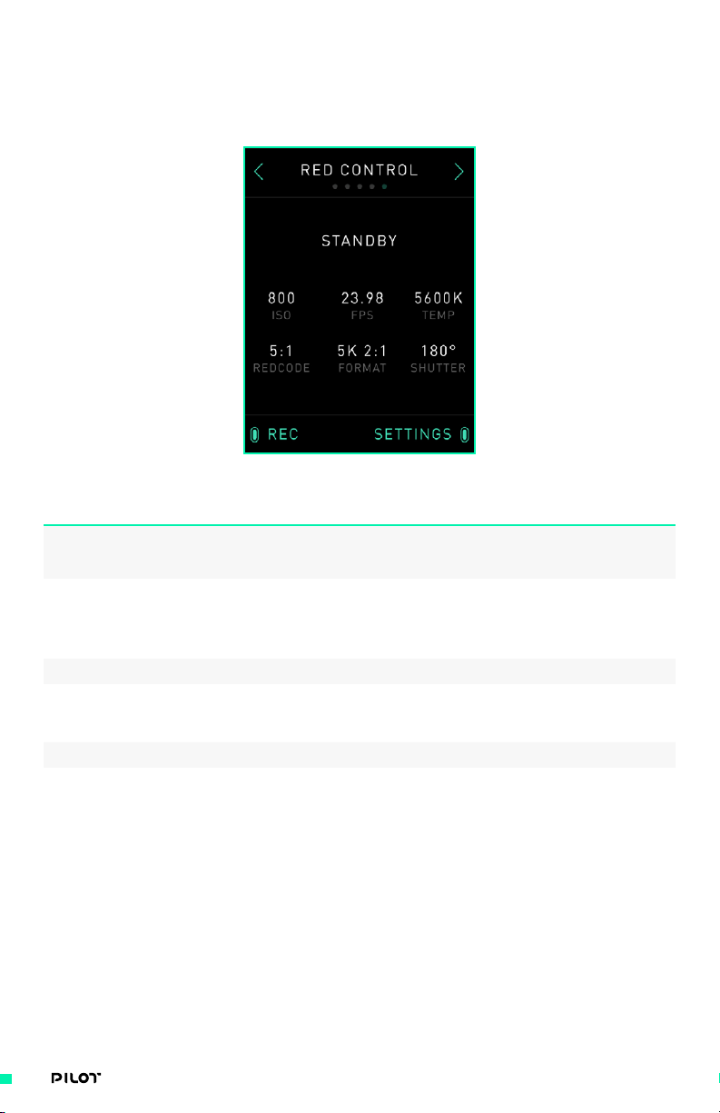
CAMERA CONTROL SCREEN
This screen allows you to start/stop recording and change camera settings. Any camera with RED
RCP is supported for changing camera settings on the fly via MIMIC display.
OPTIONS DESCRIPTION
1. Camera Status Display Displays the current status
of the connected camera.
Displays the current settings
2. Camera Settings Display
3. Record Toggles camera recording.
4. Settings Allows users to toggle through each
5. Next Screen Button Takes users to the next screen.
6. Previous Screen Button Takes users to the previous screen.
of the connected camera.
configurable camera setting and
increase or decrease the value.
50| OPERATION MANUAL
Page 51

INPUT SETUP SCREEN
This screen allows you to map inputs on the Pilot Iris / Zoom Module and Pilot Focus Module to
different outputs. When a device is connected to MIMIC, it will automatically determine which
outputs are acceptable for that specific Module/device. For more details on which devices can be
plugged into MIMIC as well as a full list of output options for each device, see Freefly Controller
Ecosystem (page 61).
OPTIONS DESCRIPTION
1. Toggle Toggles between highlighting the
available input devices.
2. Select Selects the highlighted module and takes
users to its input mapping screen.
3. Next Screen Button Takes users to the next screen.
4. Previous Screen Button Takes users to the previous screen.
51| OPERATION MANUAL
Page 52
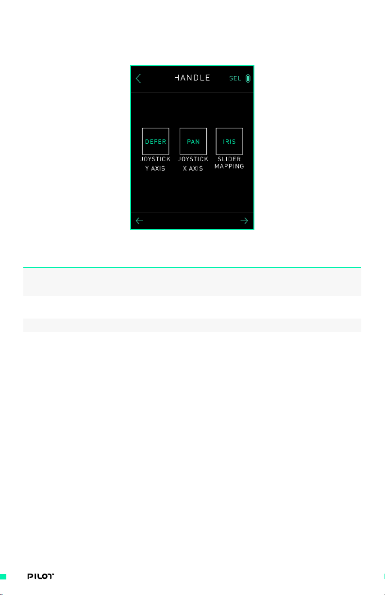
PILOT MODULE SCREEN
This screen allows you to choose an input to configure for each Module.
OPTIONS DESCRIPTION
1. Toggle Toggles between highlighting the
available input devices.
2. Select Selects the highlighted module and takes
users to its input mapping screen.
3. Next Screen Button Takes users to the next screen.
4. Previous Screen Button Takes users to the previous screen.
52| OPERATION MANUAL
Page 53

INPUT MAPPING SCREEN
This screen allows you to choose the output that the selected input will be mapped to.
OPTIONS DESCRIPTION
1. Output Visual Displays the current output that
the selected input is mapped to.
2. "+" Button Sets the output to be the one
below the current output.
3. "-" Button Sets the output to be the one
above the current output.
4. Previous Screen Button Takes users to the previous screen.
53| OPERATION MANUAL
Page 54

GAMEPAD SCREEN
This screen allows you to connect and control the MIMIC Module with the Gamepad.
OPTIONS DESCRIPTION
1. Turn On/Turn Off Enables or disables Gamepad control
2. Next Screen Button Takes users to the next screen.
3. Previous Screen Button Takes users to the previous screen.
through USB. See Freefly Controller
Ecosystem, page 64, for Gamepad setup.
54| OPERATION MANUAL
Page 55

Mō VI TUNING SCREEN
This screen allows you to perform manual tuning adjustments to the connected MōVI.
OPTIONS DESCRIPTION
1. Toggle Toggles through the stiffness and
filter parameters for each axis.
2. Select Selects the highlighted parameter
and moves to the respective
parameter adjustment screen.
3. Stiffness Values (Pan, Roll, Tilt) Displays a visual of the Pan, Roll,
and Tilt stiffness values.
4. Filter Values (Pan, Roll, Tilt) Displays a visual of the Pan,
Roll, and Tilt filter values.
5. Next Screen Button Takes users to the next screen.
6. Previous Screen Button Takes users to the previous screen.
55| OPERATION MANUAL
Page 56
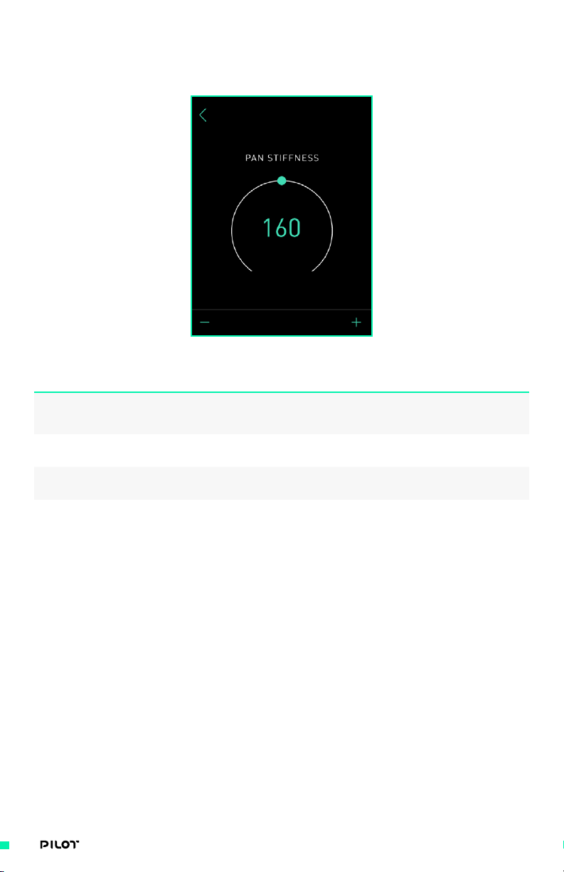
PARAMETER ADJUSTMENT SCREEN
This screen allows you to adjust the selected parameter.
OPTIONS DESCRIPTION
1. Previous Screen Button Takes users to the previous screen.
2. "+" Button Increases the value of the parameter
by (1) if pressed and (5) if held.
3. "-" Button Decreases the value of the parameter
by (1) if pressed and (5) if held.
56| OPERATION MANUAL
Page 57

RADIO SCREEN
This screen allows you to select the MōVI’s receiver channel, bind the MIMIC to a MōVI, and set the
MIMIC’s output priority.
OPTIONS DESCRIPTION
1. Radio Status Displays the signal status and strength.
2. Toggle Toggles through Channel, Bind,
3. Select Selects the highlighted parameter
4. Channel Allows the user to select the
5. Bind Allows the user to bind the
6. Priority Allows the user to set the
7. Previous Screen Button Takes users to the previous screen.
and Priority parameters.
and moves to the respective
parameter adjustment screen.
MIMIC’s radio channel.
MIMIC to a Dual-Op device.
priority of the MIMIC’s outputs.
See Freefly Controller Ecosystem,
page 61, for more information
57| OPERATION MANUAL
Page 58

USING THE MOBILE APP
The Freefly MōVI Pro App grants users additional control over the MIMIC
and its settings. The app is designed to be intuitive and easy to use while not
limiting MIMIC’s versatility.
CONNECTING TO THE MIMIC USING BLE
Before you can use a mobile device to configure your MIMIC you must first connect the two devices
using BLE. The following instructions will help you connect your MIMIC to any compatible iOS or
Android device.
1. Turn on the MIMIC by pushing the power button and allow it to fully initialize.
2. Open the Freefly MōVI app on an iOS or Android mobile device; you may have to download
the app from the respective devices’ app market. Connect to the MIMIC by selecting
“Connect” on the app’s home screen and then choosing the MIMIC you are using.
58| OPERATION MANUAL
Page 59
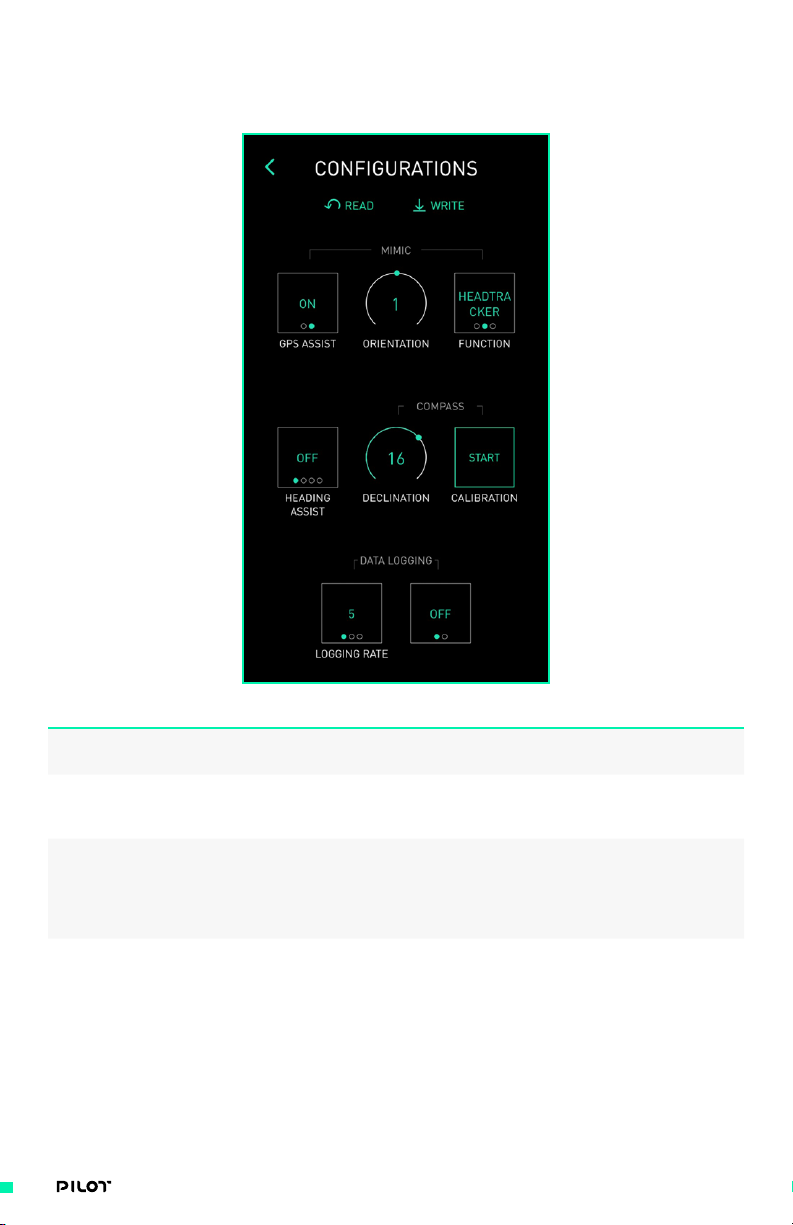
CONFIGURATIONS MENU
MIMIC’s settings are accessible through the Configurations menu on the Freefly MōVI Pro App.
OPTIONS DESCRIPTION
1. GPS Assist Use this setting when using
the MIMIC as a target
2. Orientation Use to change the MIMIC tilt orientation
in reference to the connected MōVI (Pro
or later) while button is depressed.
3. Function Use this to change the function of the
the MIMIC. Normal (Headtracker) operates
the MIMIC as standard. Target mode will
make the the MōVI point at the MIMIC,
and None will disable the MIMIC.
4. Heading Assist Use to orient the MIMIC under different
circumstances; “ OFF” is default, “GPS”
should be used in high acceleration
situations, and “Compass” can be used
for general MIMIC use. A Declination
value should be set when in Compass.
59| OPERATION MANUAL
Page 60

OPTIONS DESCRIPTION
5. Declination Set the declination angle when
using the “Compass” Heading Assist
mode. A declination angle is used
to adjust for the Earth’s magnetic
variance due to global position.
6. Calibration Calibrate the compass on the MIMIC
to increase the performance of the
Compass Heading Assist mode. Follow the
instructions provided by the app when
initializing a compass calibration.
7. Logging Rate Select MIMIC’s data logging rate.
8. Data Logging Enable the MIMIC’s data logging
function via a MicroSD card.
9. Motion Booting Enable “Motion Booting” to allow MIMIC
to boot in situations where there
is significant movement during the
initialization process of the gimbal.
For optimum performance in normal use,
motion booting should be turned off.
60| OPERATION MANUAL
Page 61

FREEFLY CONTROLLER ECOSYSTEM
Freefly offers a wide variety of handheld controllers suited to aerial, cinema
and RC professionals. With the introduction of MIMIC and Pilot Modules,
Freefly now offers a more compact, modular controller that works seamlessly
with existing controllers such as the MōVI Controller.
As MIMIC is at the heart of Pilot control, this section discusses in depth
MIMIC input devices and multi-controller priorities. It will break down all of
the different devices which can be connected to MIMIC (physically or BLE)
and MōVI, as well as why each device is assigned a “priority” when multiple
devices are connected to a single MōVI. For more information on other Freefly
controllers, please refer to respective user manuals.
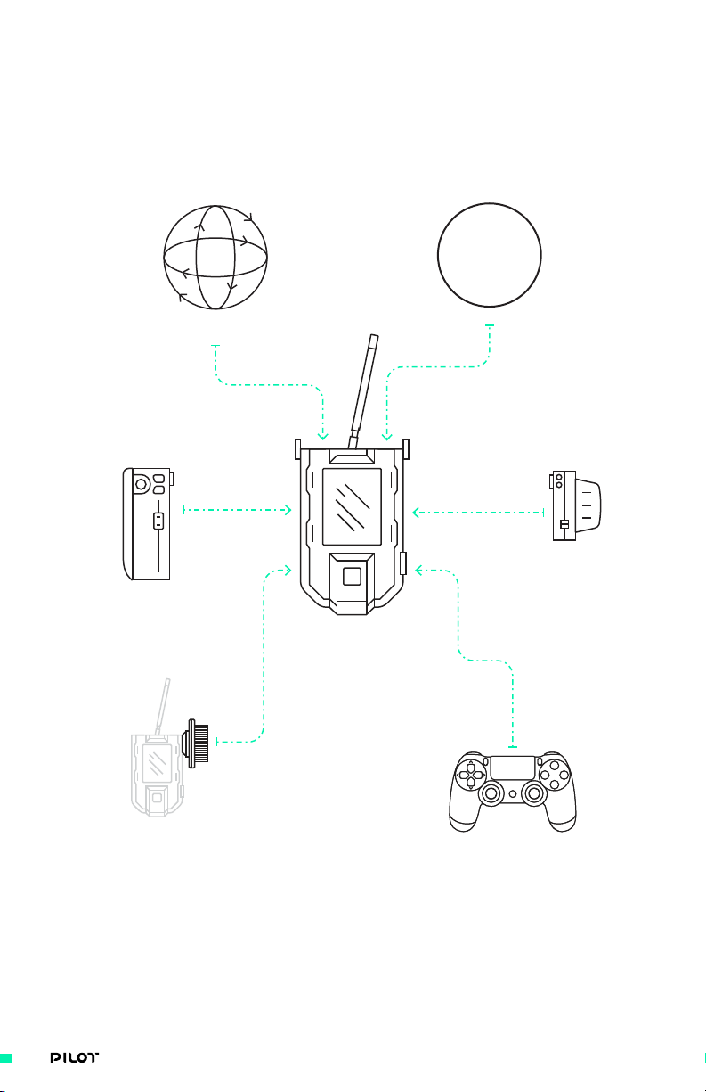
MIMIC INPUT DEVICES
MIMIC can be used on its own or expanded with a wide range of input devices. These devices allow
for enhanced control and creative flexibility over the six different axes of Pan,Tilt, Roll, Focus, Iris,
and Zoom. The following section will provide more detail on which axes which can be mapped to
each device.
Gestural
Bush Pilot
PILOT
Iris/Zoom Module
MIMIC
PILOT
Focus Module
API
Gamepad
61| OPERATION MANUAL
Page 62

INPUT DEVICE DESCRIPTION
1. MIMIC IMU MIMIC's internal IMU can be used to
control any axis with Gestural Control
2. PILOT-Iris/Zoom Module The Pilot Iris/Zoom Module has a
precision linear slider, aircraft-grade
two-axis joystick and tactile buttons
for advanced control of any axis.
3. Bush Pilot Bush Pilot is a compact rotary
encoder knob that allows for exact
control of any FIZ axis.
4. API Freefly's Application Programming
Interface allows anyone to control all
axes with a DIY or 3rd party device.
5. PILOT Focus Module The Pilot Focus Module has a 16 bit
(65,535 point resolution) rotary
encoder knob and tactile buttons for
advanced control of any FIZ axis.
6. Gamepad Gamepad is a simple option to add
tactile control over all axes.
62| OPERATION MANUAL
Page 63

CONFIGURING INPUT DEVICES
Inputs on the MIMIC can be mapped to control different axis in real-time (Pan/Tilt/Roll, Focus/
Iris/Zoom). The table below illustrates some of the different mapping options for different input
devices to MIMIC.
INPUT DEVICE DESCRIPTION
MIMIC IMU In MIMIC Main screen, MIMIC mode can
be activated to control Pan/Tilt/
Roll if Gamepad mode is not enabled.
Additionally if there are no devices
connected to MIMIC, FIZ Main screen
automatically adjusts to enable using the
internal MIMIC sensors to control Focus,
Iris or Zoom via gestures. Mapping can be
changed with “Toggle” button on MIMIC.
Bush Pilot If Gamepad mode is not ON, or there
aren’t any Pilot Modules connected to
MIMIC, FIZ Main screen will display an
option to “Toggle” mapping of Bush Pilot.
Options are Defer, Focus, Iris, Zoom
Pilot Focus Module Go to Inputs screen on MIMIC and
select Pilot Focus Module. Mapping
of the Pilot Focus Module can be set
to Defer, Focus, Iris, or Zoom.
Additionally if Pilot Handle is
not present, the “A” button on the
Pilot Focus Module can be used
to directly toggle through these
mapping options on the go.
The Default output is Focus.
Pilot Iris/Zoom Module Go to Inputs screen on MIMIC and
select Pilot Iris / Zoom Module.
Joystick Y (vertical) and X (horizontal)
axis can be set to Defer, Focus,
Iris, Zoom, Roll, Tilt or Pan.
Slider input can also be set to
Speed Adj. for controlling speed
of the Joystick Y and X inputs.
The Defaults are Zoom for Joystick Y,
Defer for Joystick X, Iris for Slider.
63| OPERATION MANUAL
Page 64

INPUT DEVICE DESCRIPTION
Gamepad Go to Gamepad screen and turn on
Gamepad mode. Mapping is done
via the gamepad buttons.
Triangle: Toggle between Dual Op mode
where MIMIC controls both Pan and
Tilt, and Majestic mode where MIMIC
defers control of MōVI axes but still
can assist with Tilt. Toggling also
resets the roll angle back to zero.
X: Puts MōVI motors in Kill state.
O: Start/Stop Record
Right Joystick: Controls pan and tilt
Arrows: Increase/decrease pan and
tilt speed adjustment applied to
right joystick. Negative values
represent flipped control direction.
Left Joystick: Vertical movement
controls the value for the assigned
axis. Assignment can be Focus, Iris,
Zoom or Roll and can be toggled by
pressing the joystick itself.
L2 R2: Increase/decrease value for
the assigned axis. Assignment can be
Focus, Iris, Zoom or Roll and can be
toggled by pressing options button.
Options: Toggles the mapping for L2 R2.
Note: When Gamepad mode is ON,
DualShock controller will charge
itself from MIMIC’s internal battery.
It is recommended to turn the mode
OFF when not in use to save power.
API The Freefly API is an application
programming interface that allows control
of the MIMIC. By including the library in
your software project, you can control
core features such as gimbal pointing,
FIZ motor control, and camera start/stop.
No configuration is available on the
MIMIC. When an API enabled device is
connected to the MIMIC, communication
will begin automatically.
For more documentation and
examples, visit the MōVI Pro
Support page at freeflysystems.
com/support/MōVI-pro-support
64| OPERATION MANUAL
Page 65

MULTI CONTROLLER PRIORITIES
Multiple controllers can be connected to a single MōVI at the same time, so the MōVI must
determine which controllers have ‘priority’ over the next. By doing this, it prevents multiple
controllers fighting to execute control over a given task, such as Focus, Iris or Zoom axes. Two
connected devices may not control the same axis; when multiple devices are connected (mapped)
to control the same setting, only the one with the highest priority will be given control.
MōVI accepts the highest available priority input and ignores the lower priority inputs for each
individual axis.
Similarly, MIMIC can have simultaneous inputs and follows its own set of priorities to automatically
determine which device has control of each task.
MōVI PRIORITIES
This table lists the order of priority for each device capable of sending an input to a MōVI.
PRIORITY CONTROLLER
1 MIMIC 1
2 MIMIC 2
3 COM 2
4 COM 1
5 Mobile App
MIMIC PRIORITIES
This table lists the order of priority for each device capable of sending an input to a MIMIC.
PRIORITY CONTROLLER
1 COM 2 API
2 COM 1 API
3 Pilot Focus Module
4 Pilot Iris/Zoom Module
5 Gamepad
6 Bush Pilot
7 MIMIC IMU
65| OPERATION MANUAL
Page 66

MōVI INPUT AXIS
This table displays which axes the MōVI inputs are capable of controlling.
CONTROLLER
/ AXIS
MIMIC 1
MIMIC 2
COM 2
COM 1
Mobile App
PAN TILT ROLL KILL FOCUS IRIS ZOOM
• • • •
• • • • • • •
• • • •
• • • • • • •
• •
• • •
MIMIC INPUT AXES
This table displays which axes the MIMIC inputs are capable of controlling.
CONTROLLER
/ AXIS
COM 2 API
COM 1 API
Pilot Focus
PAN TILT ROLL KILL FOCUS IRIS ZOOM
• • • •
• • • • • • •
• • •
• • •
Module
Pilot Iris /
• • • • • •
Zoom Module
Gamepad
Bush Pilot
MIMIC Sensor
• • • • • • •
• • •
• • • • • • •
66| OPERATION MANUAL
Page 67

Trouble Shooting
TROUBLESHOOTING
67| OPERATION MANUAL
Page 68

SYMPTOMS POSSIBLE CAUSE POSSIBLE SOLUTION
MIMIC will not turn on Battery is not charged
Battery is damaged
Plug USB into
charger and MIMIC
MIMIC is in shipping mode
MIMIC radio will not
successfully bind to
MōVI. It is shown as
“not connected” on
radio screen of MIMIC
Radio interference due
to high power antennas
being too close together
Priority is not set
to “1” on MIMIC
Software incompatibility
Try moving further away
from MōVI when binding
Set priority to “1” and
try to bind again
Make sure you have
downloaded v1.3 or later
FIZ Axis range is not
working correctly- full
range not shown on MIMIC
Focus Module Knob- Axis
not starting from “0 %”
MIMIC is turned ON but
no response on screen
when using the module
Unable to change lens motor
settings (damping, range,
etc.)in FIZ Setup screen
Iris/Zoom Module Joystick
direction is reversed
Iris/Zoom Module Joystick
axes not responding
Iris/Zoom joystick is
drifting very slowly
Single magenta blink
when calibrating Knob
module but no activity
LED color (other than
blue) when engaging
bootloader mode
Calibration issue
Cable damaged or loose
Repeat calibration
on modules shown in
Appendix section
Ensure cables do not have
any loose connections
Calibration issue Repeat calibration
of Focus Module. See
Appendix section
Cable damaged or loose
Inputs are mapped to
outputs other than FIZ
Ensure cables do not have
any loose connections
Replace cable and try again
Verify inputs are mapped
to FIZ (FIZ Config MIMIC
screen). Only FIZ axes
values will be represented
FIZ setup requires MIMIC
to be bound to MōVI (TSU)
Bind/Connect to MōVI
and try again
for proper functionality
Calibration directions
were flipped
Perform calibration again
with MIN then MAX sequence
Calibration issue Perform calibration
sequence (Reference
Appendix for more details)
Startup zero calibration
was not accurate
Restart the unit, if
it’s still drifting then
perform calibration
sequence again (Reference
Appendix for more details)
You pressed button A for
10 seconds instead of
Use button B to enter
knob calibration
B. Click A again to get
back to normal mode and
use button B to enter
knob calibration.
You are not in
bootloader mode
Enter bootloader mode
again by holding down
button A while plugging
in the USB cable
68| OPERATION MANUAL
Page 69

SYMPTOMS POSSIBLE CAUSE POSSIBLE SOLUTION
After copying the firmware
file and rebooting, green
LED blink followed by
a red blink then the
Invalid firmware copied
to module storage
drive. Module firmware
was not updated
Repeat bootloader
process again and make
sure you copy the
correct firmware file
module booted up again
After copying the firmware
file and rebooting,green
LED blink then a solid
Firmware update was
not successful
Repeat bootloader process
again. (press A while
plugging into USB port)
red (or any other color)
69| OPERATION MANUAL
Page 70

AppendixPilot
APPENDIX
70| OPERATION MANUAL
Page 71

CALIBRATION OF PILOT MODULE INPUTS
Your Pilot will arrive fully tuned, calibrated and configured to work with your
setup right out of the box. That said, it is possible for any precise system to
slightly drift or change over time so it may be necessary to calibrate inputs.
KNOB CALIBRATION (FOCUS MODULE)
1. Press button B until you see double magenta blink (it will take 10 seconds).
2. Move knob to minimum position.
3. Click button B once
4. Move knob to maximum position
5. Click button B once. You will see another double magenta
blink, which means you exited calibration mode.
SLIDER CALIBRATION (IRIS/ZOOM MODULE)
1. Press button B until you see double magenta blink (it will take 10 seconds).
2. Move slider all the way to minimum (down) position.
3. Click button B, you will see a single magenta blink.
4. Move slider all the way to maximum (up) position.
5. Click button B again, you will see a double magenta blink, which means you exited
calibration mode.
If you see different LED sequence that means
calibration was not successful, repeat again.
NOTE
71| OPERATION MANUAL
Page 72

JOYSTICK CALIBRATION (IRIS/ZOOM MODULE)
1. Press button A until you see double magenta blink (it will take 10 seconds).
2. Move joystick all the way to Y minimum (down) position and hold in this position.
3. Click button A, you will see a single magenta blink.
4. Leave joystick centered and click button A again, you will see a single magenta blink.
5. Move joystick all the way to Y maximum (up) position and hold in this position.
6. Click button A, you will see a single magenta blink.
7. Move joystick all the way to X minimum (left) position and hold in this position.
8. Click button A, you will see a single magenta blink.
9. Leave joystick centered and click button A again, you will see a single magenta blink.
10. Move joystick all the way to X maximum (right) position and hold in this position.
11. Click button A again, you will see a double magenta blink, which means you exited
calibration mode.
If you see different LED sequence that means
calibration was not successful, repeat again.
NOTE
NOTE
If you want to physically disable one axis, click through
its calibration routine without moving the joystick knob.
72| OPERATION MANUAL
Page 73

FACTORY RESET (BOTH MODULES)
In case it is desirable to “reset” your module to factory default settings, the
below procedure can be followed. This will reset to factory settings, clearing
any custom calibration that has been done on modules.
1. Press both buttons simultaneously. You will see a magenta blink after 10 seconds.
2. If factory reset is successful and EEPROM is erased you will see green LED blink and then
the module will restart automatically.
You need to redo factory calibration
NOTE
3. If factory reset failed, you will see a red LED blink. Just reset and try again.
after each factory reset.
73| OPERATION MANUAL
Page 74

UPDATING FIRMWARE (BOTH MODULES)
When new firmware versions are released, they will be accessible for
download on the Freefly Support page on the website. Simply navigate to Pilot
Controller→ Software→ Firmware release. More information can be found
here: http://freeflysystems.com/support.
1. Hold down button A and plug in your Pilot module USB cable into a PC or MAC.
2. The module pops up as a mass storage drive and LED turns blue.
3. Copy the appropriate firmware file to the drive.
4. Power-cycle the module (unplug and plug again) - without pressing any key.
5. The module LED turns green and blinks three times if firmware was updated successfully.
It will reboot automatically to normal application.
If you don’t see the three green blinks or if you
NOTE
see any other color, repeat the process again.
To download the most current user manual for the
PILOT and all other Freefly products, please visit
http://freeflysystems.com/software-manuals
@freeflysystems | #freeflyers
74| OPERATION MANUAL
 Loading...