


AIRCRAFT FLIGHT MANUAL
770-00042 | REVISION D | 01.16.2017

REVISION HISTORY
REVISION |
DATE |
DESCRIPTION |
|
|
|
A |
July 2015 |
Initial Release |
B |
August 2015 |
Revised section order. Added Allowable Gross Weight table. |
C |
October 2015 |
Revised for clarity. Added Disarm Safety function and WiFi password |
|
|
reset information. Revised default tuning values to reflect SYNAPSE |
|
|
version 3.4. |
D |
January 2017 |
Added discussion of features available in SYNAPSE version 4.0.4. Added |
|
|
Kinematic Position Mode. Added Orbit Mode. Updated Alarm Light |
|
|
scenarios. Added procedure to disable ceiling and range limits. Updated |
|
|
Autoland descent rate. Updated default settings, switch functions, and |
|
|
data logging fields. General updates and typographical fixes. Revised |
|
|
name to ALTA 6. Added additional maintenance items, motor alignment |
|
|
process, additional troubleshooting information. Fixed errata. |
ALTA 6 AIRCRAFT FLIGHT MANUAL DOCUMENT NUMBER: 770-00042

CONTENTS
2Revision History
3Table of Contents
6 ALTA 6 OVERVIEW
7Disclaimer and Warning
9Limitation of Liability
10Introduction
11Symbols, Abbreviations, and Terminology
14 Dimensions
16Included Items
17Specifications
21 |
Limitations |
23 |
System Diagrams |
27ALTA Mobile App
28Additional Required Components (not included)
29 SETTING UP ALTA 6
30Unfolding/Folding ALTA 6
33 |
Radio Installation |
38 |
Radio Channel Mapping |
44 |
Configuring for MōVI |
46Isolator Cartridges
47Battery Installation
52 |
Compass Calibration |
55 |
Propellers |
57 |
First Person View (FPV) |
64 |
Tuning ALTA 6 |
68 |
ALTA 6 Flight Parameters |
72Resetting ALTA 6 WiFi Password
73 OPERATING ALTA 6
74Flight Controller Modes
79 |
Home Switch |
|
| AIRCRAFT FLIGHT MANUAL |
3 |
|

80Orbit Switch
81Disarm Safety Switch
82Status Light
84Orientation Lights
85Alarms
86ALTA App Monitor
87Data Logging
88 NORMAL PROCEDURES
89Unpacking and Setup
90Before Starting
92 |
Before Takeoff |
94 |
After Every Flight |
96After Last Flight
97 EMERGENCY PROCEDURES
98Emergency Guidance
99Alarm Indication (Flashing or Solid Red Light)
100Pilot Loss of ALTA 6 Orientation
101Unexpected Flight Controller Behavior
102Battery Exhaustion
103Radio Loss of Signal (LOS)
104Loss of FPV Signal
105 PERFORMANCE
106Weight / Endurance Performance Data
107Allowable Gross Weight
108 MAINTAINING ALTA 6
109General Information and Techniques
110Maintenance Items
114Firmware Update Process
115Motor Alignment
118 |
Guidelines Following an Accident |
|
| AIRCRAFT FLIGHT MANUAL |
4 |
|

119 TROUBLESHOOTING
124 APPENDIX
125Appendix A. Default Tuning Values
126Appendix B. Data Logging Fields
|
| AIRCRAFT FLIGHT MANUAL |
5 |
|
ALTA 6 OVERVIEW
|
| AIRCRAFT FLIGHT MANUAL |
6 |
|

DISCLAIMER AND WARNING
IMPORTANT - Please read this disclaimer and warning carefully and review
the ALTA 6 Aircraft Flight Manual (AFM) prior to flight. If you have any questions, please contact support@freeflysystems.com prior to using the ALTA 6. You can review the most current version of this AFM at www.freeflysystems.com/software-manuals/.
By using ALTA 6, you acknowledge that you have read, understand and agree to this disclaimer. You agree that you are solely responsible for your conduct while using ALTA 6, and for any direct or indirect consequences that may result from its use. You agree to only use ALTA 6 for proper purposes that are in accordance with local and airspace rules and regulations.
»» ALTA 6 is not a toy and should be operated with extreme care, as improper operation can cause damage to property, serious personal injury or death.
»» As with any multi-rotor aircraft, ALTA 6 is a complex and technical machine. Novice pilots should invest sufficient time on a flight simulator and seek training from an experienced pilot prior to operation. The ALTA 6 Aircraft Flight Manual and a flight simulator are no substitute for training with an experienced pilot, particularly when it comes to learning how to safely operate ALTA 6. Novice pilots should never fly without the supervision of an experienced pilot.
»» Always check ALTA 6 and its components prior to operation. »» Always maintain a safe distance from ALTA 6 when in use.
»» Never attempt to touch ALTA 6 when the propellers are moving.
»» Never fly ALTA 6 over or around people, power lines or other aircraft.
»» Never fly with any propellers that have visible imperfections or damage.
»» Always keep children and animals a safe distance away from ALTA 6 when in use and when changing configurations.
»» Only use propellers supplied by Freefly Systems that are designed for use on ALTA 6.
»» Always remove the propellers or power ALTA 6 using a low power source when making a change to the configuration of ALTA 6 to prevent propeller strikes in the event of unintentional motor starts.
»» Always remove the configuration jumper when making changes to the configuration of ALTA 6.
»» Always test ALTA 6 with the propellers removed to make sure that the motors are spinning in the correct direction and that the motor assignment is correct with respect to the SYNAPSE flight controller. If you have either of these wrong, the ALTA 6 will be uncontrollable and dangerous.
»» It is your responsibility to perform a full system check of ALTA 6 prior to every flight.
»» It is your responsibility to learn how to safely operate ALTA 6 and to adhere
|
| AIRCRAFT FLIGHT MANUAL |
7 |
|

to all applicable rules and regulations. »» Fly at your own risk.
»» ALTA 6 is a tuned system with custom components selected for each application. Modification to, removal, or substitution of ALTA 6 components will void the warranty and can lead to unsafe operating conditions.
|
| AIRCRAFT FLIGHT MANUAL |
8 |
|

LIMITATION OF LIABILITY
IN NO EVENT SHALL FREEFLY BE LIABLE TO BUYER FOR ANY INDIRECT, CONSEQUENTIAL, PUNITIVE, INCIDENTAL, OR SPECIAL DAMAGES, OR ANY DAMAGES WHATSOEVER RESULTING FROM THE USE OF ALTA OR FROM LOSS OF USE, DATA
OR PROFITS (HOWEVER CAUSED AND UNDER ANY THEORY OF LIABILITY), EVEN IF FREEFLY HAS BEEN ADVISED OF THE POSSIBILITY OF SUCH DAMAGES. IN NO EVENT SHALL FREEFLY’S LIABILITY FOR A PRODUCT (WHETHER ASSERTED AS A
TORT CLAIM, A CONTRACT CLAIM OR OTHERWISE) EXCEED THE AMOUNTS PAID TO FREEFLY FOR SUCH PRODUCT. NOTWITHSTANDING ANYTHING HEREIN, IN NO EVENT SHALL FREEFLY’S LIABILITY FOR ALL CLAIMS ARISING OUT OF OR RELATING TO THIS AGREEMENT EXCEED THE AMOUNTS PAID BY BUYER TO FREEFLY FOR PRODUCT IN THE LAST TWELVE (12) MONTHS. IN NO EVENT WILL FREEFLY BE LIABLE FOR COSTS OF PROCUREMENT OR SUBSTITUTE GOODS BY BUYER. THE LIMITATIONS SET FORTH HEREIN SHALL APPLY TO ALL LIABILITIES THAT MAY ARISE OUT OF THIRD-PARTY CLAIMS AGAINST BUYER. THESE LIMITATIONS SHALL APPLY NOTWITHSTANDING ANY FAILURE OF ESSENTIAL PURPOSE OF ANY LIMITED REMEDY.
Freefly shall not be liable for damages or injuries incurred directly or indirectly from the use of ALTA 6 including, but not limited to, the following situations:
»» Failure of operator to follow proper instructions and safety warnings found at www.freeflysystems.com.
»» Failure of the operator to understand and operate the aircraft within the operating limitations described in this manual.
»» Failure of the operator to follow onboard safety warnings while using ALTA 6.
»» Failure of the operator to follow and comply with local rules and regulations.
»» Failure of the operator to inspect ALTA 6 and its components prior to operation.
»» Failure of the operator to properly maintain and/or service ALTA 6 through an authorized Freefly Service Center with genuine ALTA 6 parts.
»» Use of third-party products on ALTA 6.
»» Use of ALTA 6 in a physically or mentally impaired capacity.
»» Use of ALTA 6 without sufficient training.
»» Use of ALTA 6 in unsafe conditions, including but not limited to, bad or severe weather, such as rain, wind, snow, lightning, dust storms, etc., or in areas of magnetic or radio interference, such as power stations, broadcasting and cell phone towers, government prohibited airspace, etc.
»» Improper operation, misjudgment or risky behavior while using ALTA 6.
»» Infringement of third party data, audio or video rights recorded when using ALTA 6.
|
| AIRCRAFT FLIGHT MANUAL |
9 |
|

INTRODUCTION
ALTA 6 is a professional multi-rotor aircraft designed for demanding cinematic, television, and photographic applications. Within five minutes, ALTA 6 can unfold from its carrying case to flying some of the most capable cinema cameras on either the top or bottom of the aircraft. The SYNAPSE flight controller is purpose-built for cinema use, yielding precise yet smooth control.
This Aircraft Flight Manual has been prepared to describe the complete operation of airframe and flight control systems, and the normal maintenance of those items. Do not operate ALTA 6 without reading and understanding this manual.
This manual is not a substitute for adequate flight training. Training requirements can vary when operating in different countries or under different flight conditions. Always consult local regulations before flying ALTA 6. In areas where there are no flight training requirements, it is the sole determination of the pilot-in-command as to whether he or she has the appropriate level of training or experience for a given flight. Always set and adhere to personal minimums and fly within your own capabilities.
|
| AIRCRAFT FLIGHT MANUAL |
10 |
|
SYMBOLS, ABBREVIATIONS, AND TERMINOLOGY
WARNINGS, CAUTIONS AND NOTES
Throughout the manual, warnings, cautions and notes are used to highlight various important procedures. These are defined as follows:
WARNING |
CAUTION |
NOTE |
Warnings are used to highlight procedures which, if not strictly observed, may result in personal injury or loss of life.
Cautions are used to highlight procedures which, if not strictly observed, may cause damage to equipment.
Notes are used to highlight specific operating conditions or steps of a procedure.
METEOROLOGICAL TERMINOLOGY
ISA |
International Standard Atmosphere in which: |
|
The air is a dry, perfect gas; |
|
The temperature at sea level is 15° |
|
Celsius (59° Fahrenheit); |
|
The pressure at sea level is 1013.2 |
|
mbar (29.92 inches Hg); |
|
The temperature gradient from sea level |
|
to the altitude at which the temperature is |
|
-56.5°C (-69.7°F) is -0.00198°C (-0.003564°F) |
|
per foot and zero above that altitude |
|
|
MSL |
Mean Sea Level is the average height above |
|
the surface of the sea for all stages of tide |
|
|
AGL |
Above Ground Level is the height of |
|
the aircraft above the ground |
|
|
OAT |
Outside Air Temperature is the free air static |
|
temperature surrounding the aircraft |
|
|
|
| AIRCRAFT FLIGHT MANUAL |
11 |
|

Pressure Altitude |
Altitude measured from standard sea level |
|
pressure (1013.2 mbar, 29.92 in. Hg) by a |
|
pressure or barometric altimeter |
|
It is the indicated pressure altitude corrected for |
|
position and instrument error. In this Manual, |
|
altimeter instrument errors are assumed to be zero |
|
|
POWER TERMINOLOGY
Maximum Continuous |
The maximum typical power output of a |
Power Output |
motor averaged over the entire flight |
|
|
Maximum Instantaneous |
The maximum power output of a motor during |
Peak Power Output |
any phase of flight, such as when maneuvering |
|
|
FLIGHT AND POWERPLANT CONTROL
Throttle Stick |
The radio controller stick responsible for |
|
throttle control. For Mode 2 controllers, this |
|
is the vertical movement of the left control |
|
stick. For Mode 1 controllers, this is the |
|
vertical movement of the right control stick |
|
|
Yaw Stick |
The radio controller stick responsible |
|
for yaw (also called pan) control |
|
For Mode 2 and Mode 1 controllers, this is the |
|
lateral movement of the left control stick |
|
|
Pitch Stick |
The radio controller stick responsible for |
|
pitch control. For Mode 2 controllers, this is |
|
the vertical movement of the right stick |
|
For Mode 1 controllers, this is the |
|
vertical movement of the left stick |
|
|
Roll Stick |
The radio controller stick responsible for roll |
|
control. For Mode 2 and Mode 1 controllers, this is |
|
the lateral movement of the right control stick |
|
|
Pitch/Roll Stick |
The radio control stick responsible |
or Cyclic Stick |
for both pitch and roll control |
|
For Mode 2 controllers, this is the right stick |
|
|
|
| AIRCRAFT FLIGHT MANUAL |
12 |
|

WEIGHT AND BALANCE
Maximum Takeoff |
Maximum allowable weight at liftoff |
Weight (MTOW) |
|
|
|
Standard Empty Weight |
Weight of a standard aircraft |
|
|
Basic Empty Weight |
Standard empty weight plus optional equipment |
|
|
Useful Load |
Difference between take off weight |
|
and basic empty weight |
|
|
Payload |
Useful load less battery weight |
|
|
GENERAL TERMINOLOGY
LOS |
Loss of Signal |
|
|
RTH |
Return-to-Home |
|
|
sUAS |
Small Unmanned Aircraft System includes all |
|
components of the system required for the flight of |
|
an unmanned aircraft, including the radio controller, |
|
data link and other related support equipment |
|
|
|
| AIRCRAFT FLIGHT MANUAL |
13 |
|

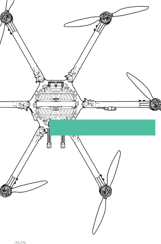
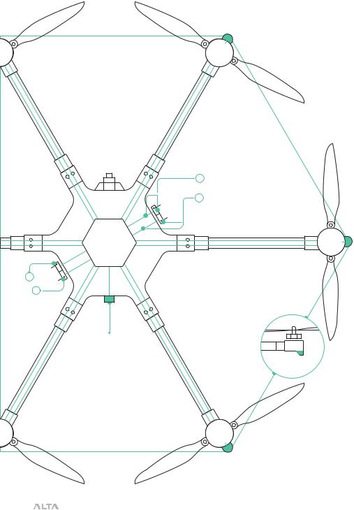
DIMENSIONS
1533
(60.4)
1064
(41.9)
6
1
5
2
4 |
457 |
3 |
(18.0)
UNFOLDED PLAN VIEW WITH BOOM NUMBERING SCHEME MM (INCH)
318
(12.5)
180
(7.1)
UNFOLDED SIDE VIEW WITH LANDING GEAR MM (INCH)
178
(7.0)
1126
(44.3)
UNFOLDED FRONT VIEW WITHOUT LANDING GEAR MM (INCH)
|
| AIRCRAFT FLIGHT MANUAL |
14 |
|

220
(8.7)
FOLDED SIDE VIEW MM (INCH)
550
(21.7)
FOLDED PLAN VIEW MM (INCH)
515 |
(20.3) |
180
(7.1)
205
(8.1)
FOLDED FRONT VIEW MM (INCH)
|
| AIRCRAFT FLIGHT MANUAL |
15 |
|

INCLUDED ITEMS
1.Case
2.ALTA 6
3.Case Lid Foam
4.Isolator Cartridges
a.(6) Teal (Installed)
b.(6) Black
c.(6) Red
5.Documentation
6.USB-Futaba Power Cable
7.Inverted Landing Gear
8.Antenna Tubes
9.FPV Cables
a.Skyzone/BOSCAM
b.BOSCAM, small connector
c.ImmersionRC/Fat Shark
d.Ready Made RC
| AIRCRAFT FLIGHT MANUAL
10.Fasteners
a.(4) M3 × 8 Socket Head for Toad In The Hole Male Adapter
b.(2) M3 × 8 Flat Head for Accessory Mount
11.Toad In The Hole Male Adapter
12.5.5mm Wrench
13.Hex Drivers (1.5mm, 2.0mm, 2.5mm)
14.Accessory Mount
15.Double-Sided Tape
16.Electronic Luggage Scale
16

SPECIFICATIONS
DIMENSIONS
Unfolded Diameter |
1126 mm |
(does not include Props) |
|
Folded Diameter |
550 mm |
(does not include Props) |
|
Height to base of Toad In The Hole (TITH) |
220 mm |
POWERPLANT
Number of Motors |
6 |
Motor Type |
Direct Drive 3-Phase PMAC Outrunner |
Motor Make and Model |
Freefly F45 |
Motor Max Continuous Power Output |
350 W |
Motor Max Instantaneous |
950 W |
Peak Power Output |
|
Maximum RPM (flat rated) |
6300 RPM |
Equivalent Kv |
384 |
Electronic Speed Controller |
Freefly Silent-Drive Sine Wave ESC |
PROPELLERS
Make and Model |
Freefly ALTA Propeller |
Material |
Carbon fiber with balsa core |
Propeller Orientation |
(4) CW and (4) CCW Props |
Propeller Type |
18 × 6 Folding |
BATTERY
|
Nominal Battery Voltage |
6S / 22.2V |
|
Maximum Battery Size (GroundView) |
240 × 175 × 80 mm |
|
Maximum Battery Size (SkyView) |
220 x 156 x 64 mm |
|
Maximum Battery Quantity |
2 Battery Packs (Parallel) |
|
Minimum Battery Quantity |
2 Battery Packs (Parallel) |
|
Battery Connectors |
2× EC5 (Parallel) |
|
Required Minimum Battery |
200A / 400A Peak |
|
Discharge Rating (Per Pack) |
|
|
| AIRCRAFT FLIGHT MANUAL |
17 |
|

WEIGHTS
Maximum Gross for Takeoff1 |
13.6 kg (30.0 lbs) |
Maximum Useful Load2 |
9.1 kg (20.0 lbs) |
Maximum Payload3 |
6.8 kg (15.0 lbs) |
Typical Standard Empty Weight: |
4.5 kg (10.0 lbs) |
 WARNING
Always refer to the following aircraft limitations section for complete information on allowable maximum gross weights at different altitudes and temperatures before any flight.
SPECIFIC LOADINGS
Typical Specific Power4 |
145 W/kg |
Thrust Ratio at MTOW1 |
1.85 : 1 |
1At sea level, ISA. Refer to the Weight Limitations section for complete loading information.
2Top and bottom mount. Includes batteries.
3Payload weight top or bottom mount. Battery weight not included and mounted on opposite side from payload.
4At MTOW, sea level, ISA.
|
| AIRCRAFT FLIGHT MANUAL |
18 |
|

FLIGHT CONTROLLER
Model Name |
Freefly SYNAPSE flight controller |
Flight Modes |
Manual, Height Mode, Position Mode |
|
(Classic, Kinematic), Return-to-Home |
|
(RTH), Autoland, Orbit Mode |
Supported Inputs: |
DSMX, DSM2, S.Bus, |
|
S.Bus2, PPM, FPV SD |
Supported Radios |
Futaba S.Bus & S.Bus2, DSMX, |
|
DSM2 (Spektrum/JR), PPM, |
|
PPM Invert, PPM Graupner |
Supported Radio Controller |
Futaba w/ built-in voltage sense port |
Telemetry Systems |
|
Minimum Radio Controller |
5 |
Channels Required |
|
Supported GNSS |
GPS, GLONASS, Galileo |
Supported SBAS |
QZSS, WAAS, EGNOS, MSAS |
First-Person View System |
NTSC, PAL |
Video Formats |
|
Supported First-Person |
Skyzone, BOSCAM, |
View Transmitters |
ImmersionRC, Fat Shark |
Supported First-Person View Cameras |
Ready Made RC |
|
(RMRC-700XVN Recommended) |
First-Person View OSD Telemetry |
User Configurable |
Installed Transceivers |
Wi-Fi 2.4 GHz b/g/n |
Data Logging Rate |
25 Hz |
LIGHTING AND INDICATION
Status Light |
1 Watt Red, 1 Watt White LED |
Orientation Lights |
3-Watt RGB LED |
Orientation Light Color Options |
Red, Yellow, Blue, Purple, |
|
Green, White, Off |
ISOLATION SYSTEM
|
Vibration Isolation System |
O-Rings |
|
Option 1: Soft / Light Payloads |
Red O-Rings |
|
Option 2: Medium / Medium Payloads |
Teal O-Rings |
|
Option 3: Stiff / Heavy Payloads |
Black O-Rings |
|
| AIRCRAFT FLIGHT MANUAL |
19 |
|

PAYLOAD MOUNTING
Mounting Locations |
Bottom and Top Mount |
Mounting System |
Freefly Toad In The Hole |
|
(TITH) Quick Release |
FPV Camera Mount |
Forward, underneath chassis |
FPV Transmitter Mount |
Boom 5 |
|
| AIRCRAFT FLIGHT MANUAL |
20 |
|
LIMITATIONS
 NOTE
NOTE
These limitations are advisory in nature and do not extend or restrict limitations provided by Governing Aviation Authorities.
POWERPLANT LIMITATIONS
Maximum RPM |
6300 RPM |
Maximum Battery Voltage |
25.2 Volts |
Minimum Average Battery Voltage |
19.2 Volts |
ENVIRONMENTAL LIMITATIONS
Do not fly ALTA 6 in temperatures exceeding 45ºC (113ºF) or below -20ºC(-4ºF).5
FLIGHT CONTROLLER LIMITS
Maximum Pitch/Roll Angle |
45° |
Maximum Yaw Rate |
150° / second |
5 Battery temperature ratings must be observed.
|
| AIRCRAFT FLIGHT MANUAL |
21 |
|

MANUAL FLIGHT AIRCRAFT |
22
ALLOWABLE GROSS WEIGHT
As altitude and temperature increase, the density of the air decreases. Consequently, ALTA’s thrust will decrease. The following table describes maximum gross weight limits with respect to altitude and temperature.
|
|
0ºC (32ºF) |
10ºC (50º) |
20ºC (68ºF) |
30ºC (86ºF) |
40ºC (104ºF) |
||||||
Press Alt Ft |
|
|
|
|
|
|
|
|
|
|
||
Maximum |
Maximum |
Maximum |
Maximum |
Maximum |
Maximum |
Maximum |
Maximum |
Maximum |
Maximum |
|||
|
|
|||||||||||
|
|
Gross Weight |
Gross Weight |
Gross Weight |
Gross Weight |
Gross Weight |
Gross Weight |
Gross Weight |
Gross Weight |
Gross Weight |
Gross Weight |
|
|
|
(lb) |
(kg) |
(lb) |
(kg) |
(lb) |
(kg) |
(lb) |
(kg) |
(lb) |
(kg) |
|
|
|
|
|
|
|
|
|
|
|
|
||
Sea Level |
30.0 |
13.6 |
30.0 |
13.6 |
29.5 |
13.4 |
28.5 |
12.9 |
27.6 |
12.5 |
||
|
|
|
|
|
|
|
|
|
|
|
|
|
305m |
(1000ft) |
30.0 |
13.6 |
29.4 |
13.4 |
28.4 |
12.9 |
27.5 |
12.5 |
26.6 |
12.1 |
|
|
|
|
|
|
|
|
|
|
|
|
|
|
610m |
(2000ft) |
29.4 |
13.3 |
28.4 |
12.9 |
27.4 |
12.4 |
26.5 |
12.0 |
25.7 |
11.6 |
|
|
|
|
|
|
|
|
|
|
|
|
|
|
914m |
(3000ft) |
28.4 |
12.9 |
27.4 |
12.4 |
26.4 |
12.0 |
25.5 |
11.6 |
24.7 |
11.2 |
|
|
|
|
|
|
|
|
|
|
|
|
|
|
1219m |
(4000ft) |
27.3 |
12.4 |
26.4 |
12.0 |
25.5 |
11.5 |
24.6 |
11.2 |
23.8 |
10.8 |
|
|
|
|
|
|
|
|
|
|
|
|
|
|
1524m |
(5000ft) |
26.3 |
11.9 |
25.4 |
11.5 |
24.5 |
11.1 |
23.7 |
10.8 |
23.0 |
10.4 |
|
|
|
|
|
|
|
|
|
|
|
|
|
|
1829m |
(6000ft) |
25.4 |
11.5 |
24.5 |
11.1 |
23.6 |
10.7 |
22.8 |
10.4 |
22.1 |
10.0 |
|
|
|
|
|
|
|
|
|
|
|
|
|
|
2134m |
(7000ft) |
24.4 |
11.1 |
23.5 |
10.7 |
22.7 |
10.3 |
22.0 |
10.0 |
21.3 |
9.7 |
|
|
|
|
|
|
|
|
|
|
|
|
|
|
2438m |
(8000ft) |
23.5 |
10.7 |
22.7 |
10.3 |
21.9 |
9.9 |
21.2 |
9.6 |
20.5 |
9.3 |
|
|
|
|
|
|
|
|
|
|
|
|
|
|
2743m |
(9000ft) |
22.6 |
10.3 |
21.8 |
9.9 |
21.1 |
9.6 |
20.4 |
9.2 |
19.7 |
8.9 |
|
|
|
|
|
|
|
|
|
|
|
|
||
3048m (10000ft) |
21.8 |
9.9 |
21.0 |
9.5 |
20.3 |
9.2 |
19.6 |
8.9 |
19.0 |
8.6 |
||
|
|
|
|
|
|
|
|
|
|
|
|
|
LIMITS WEIGHT
Payload Maximum
Weight Takeoff Maximum
following See |
.(15 kg 8.6 |
table |
lbs) 0 |

SYSTEM DIAGRAMS
sUAS OVERVIEW
GPS Satellite
HD Video Link, |
ALTA App |
Preview Monitor* |
FPV Rx,
Preview Monitor*
Radio Controller*
*NOT INCLUDED 


 2.4GHz MōVI Controller*
|
| AIRCRAFT FLIGHT MANUAL |
23 |
|
FLIGHT CONTROL
C
SYNAPSE
Flight
Controller
A. |
B. |
Status
Light
C
ESC
 A. Spektrum Receiver
DSMX, DSM 2
 B. Futaba Receiver or Generic Receiver
S.BUS, S.BUS 2 or PPM
P W M
ESC
C A N
6 Position Lights
ESC
|
| AIRCRAFT FLIGHT MANUAL |
24 |
|

POWER SYSTEM
Motor |
Motor |
Lights 6* |
Lights1 * |
SYNAPSE
Flight
Controller
FPV |
CAM |
|
FPV |
Tx |
|
Futba
Tel
.RE
CEI V
ER
F U S E
Motor
Lights 5*
R
E
C
E
I
V
E
R
|
|
|
|
|
|
|
|
12v |
|
5v |
|
5v |
|
|
||||||
|
|
|
|
|
|
|
|
R E G U L AT O R S |
|
|
|
||
|
|
|
|
|
|
|
EC5 Connector
Motor
Lights 4*
Flight |
Flight |
Battery |
Battery |
Motor
Lights 2*
F U S E
Note: Do not modify, augment, or add components to the electrical power system of the ALTA.
Unauthorized modifications may result in unsafe operation.
Motor
Lights 3*
| AIRCRAFT FLIGHT MANUAL |
25 |

FPV EQUIPMENT
FPV Camera (not included)
FPV Camera Cable
FPV Tx (not included)
 FPV Camera Lead
Pre-installed
SYNAPSE
Flight
Controller
FPV Tx Lead
Pre-installed
FPV Tx Cable
Boscam/Skyzone or Fat Shark/ImmersionRC
|
| AIRCRAFT FLIGHT MANUAL |
26 |
|

ALTA MOBILE APP
The ALTA App is used to configure ALTA 6 parameters, update ALTA 6 firmware, and to monitor ALTA 6 status during flight. To download the ALTA App, search for “Freefly ALTA” in the App Store or on Google Play™.
Parameters may only be adjusted while ALTA 6 is on the ground and disarmed. In addition, radio mapping parameters can only be adjusted when the Configuration Jumper is removed. For more information on radio mapping, see the Radio Mapping section of this manual.
The ALTA App will be actively maintained, and additional functionality may be added over time. For information on individual app updates, refer to the App release notes.
 NOTE
NOTE
When making configuration changes with the ALTA App, wait three seconds for the app to automatically save changes to ALTA 6 before shutting off the app or the mobile device.
|
| AIRCRAFT FLIGHT MANUAL |
27 |
|

ADDITIONAL REQUIRED COMPONENTS (NOT INCLUDED)
RADIO CONTROLLER
ALTA 6 supports a variety of radio controllers as outlined in the Flight Controller Specifications. A minimum of five (5) channels are required, with four (4) used for flight control, and the remaining one (1) used for mode selection.
However, a radio controller with at least 10 channels is highly recommended to make use of Velocity and Climb Rate Clamps, Return-to-Home (RTH), Disarm Safety, and Orbit Mode functions. It is recommended to use a radio controller with a three way switch for the Mode, Home, and Orbit functions, a two or three way switch for the disarm safety function, and a knob or slider input for both the Velocity and Climb Rate Clamp functions.
FLIGHT BATTERY
ALTA 6 can accommodate a variety of Lithium Polymer (LiPo) flight battery packs. Battery packs must be 6S, having a nominal voltage of 22.2 V. Only run ALTA 6 using two packs at a time. Each pack must have a continuous discharge rating of 200 amps or greater, and a peak discharge rating of 400 amps or greater. For additional information on expected flight durations, refer to the Performance Section of this manual.
|
| AIRCRAFT FLIGHT MANUAL |
28 |
|

SETTING UP ALTA 6
|
| AIRCRAFT FLIGHT MANUAL |
29 |
|
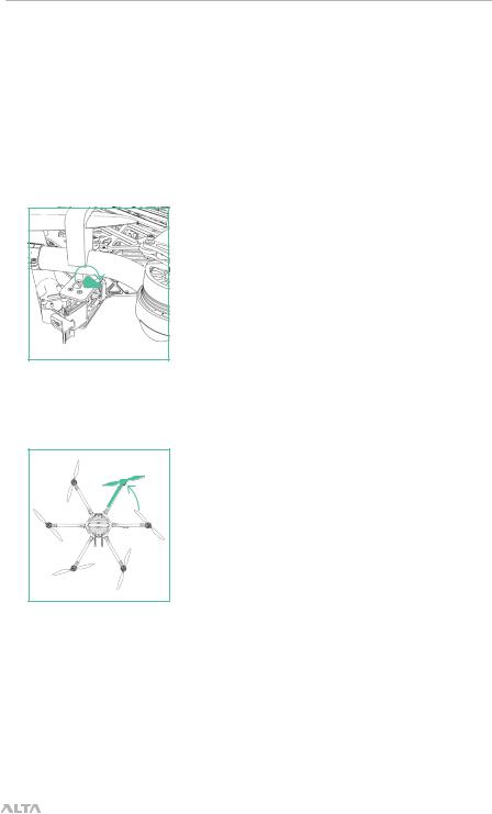
UNFOLDING ALTA 6
ALTA 6 features swan-neck booms that fold into a compact size for travel. They are secured in an open position for flight using overcenter latches.
TO UNFOLD ALTA 6
1.Remove ALTA 6 from case
2.Fold down all six boom retention clips
3.Open ALTA 6 booms. ALTA 6 can become unbalanced and tip over while unfolding booms individually, so unfold opposite boom pairs simultaneously to keep balance.
|
| AIRCRAFT FLIGHT MANUAL |
30 |
|
 Loading...