

Page 1
Page 2

P2
Freefly represents the intersection of art and technology. Our team consists of industry leading
specialists all focused on one task—inventing solutions to allow unrestricted camera movement.
Freefly initially created the CineStar line of multi-rotor camera platforms, which allowed smooth,
stable and dynamic low-altitude aerial imagery. After years of research and development in
camera stability, Freefly has created the MōVI stabilized camera gimbal. Our goal with the MōVI
is to empower a new era of stabilized cinematography on a variety of platforms, from handheld
to helicopters and everything in between.
Page 3
P3
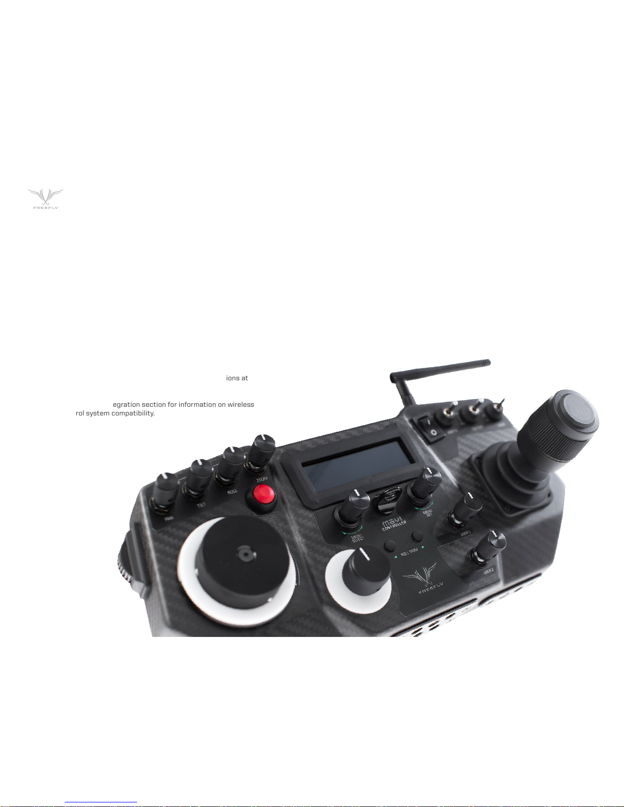
The MōVI Controller is compatible with the MōVI M5, M10, and
M15 running firmware version 3.08 or later.
Download the latest MōVI firmware and update instructions at
www.freeflysystems.com.
See Follow-Focus Integration section for information on wireless
lens control system compatibility.
COMPATABILITY
Page 4
P4
POWER INPUTS:
External DC Supply or Battery
Controller Only (No Monitor), Power Level 4
Controller and Monitor, Max
13.0 V - 20.0 V 0.2A
13.0 V - 20.0 V 3.2A
USB Controller only (No monitor), Power Level 4 4.75 V - 5.25 V 0.4A
POWER OUTPUTS:
12V DC OUTPUT
Input 13.0 - 20.0V, Output Current < 3.0A
Max. Current Output
11.4 V - 12.6 V
3.0A
USB 5V OUTPUT
Input 13.0 - 20.0V, Output Current < 2.0A
Max. Current Output
4.50 V - 5.25 V
2.0A
MōVI CONTROLLER PHYSICAL:
Weight Including Antenna, Excluding Monitor and Battery Plate 950 g
Dimensions Including Antenna and Joystick, Excluding Monitor and Battery Plate 300mm X 175mm X 120mm
RECIEVER OUTPUTS:
Weight Excluding Wires and Mounting Tape 15 g
Dimensions Excluding Wires, Mounting Tape, Antenna 33mm X 38mm X 15mm
RADIO TRANSMITTER:
Frequency All Channels 2.410 - 2.465 Ghz
Transmission Power
Power Level 0 (EU)
Power Level 4
+10 dBm
+1B dBm
Range Power Level 0 (EU), Outdoor Line-of-Sight 1200 ft / 300 m
CONTROLLER SPECIFICATIONS
Page 5
P5
CONTROLLER SPECIFICATIONS
Any MōVI M5, M10, or M15 can be configured to work with the MōVI Controller.
The MōVI must have firmware version 3.08 or later. The latest MōVI firmware,
release notes, and update instructions are available at www.freeflysystems.com
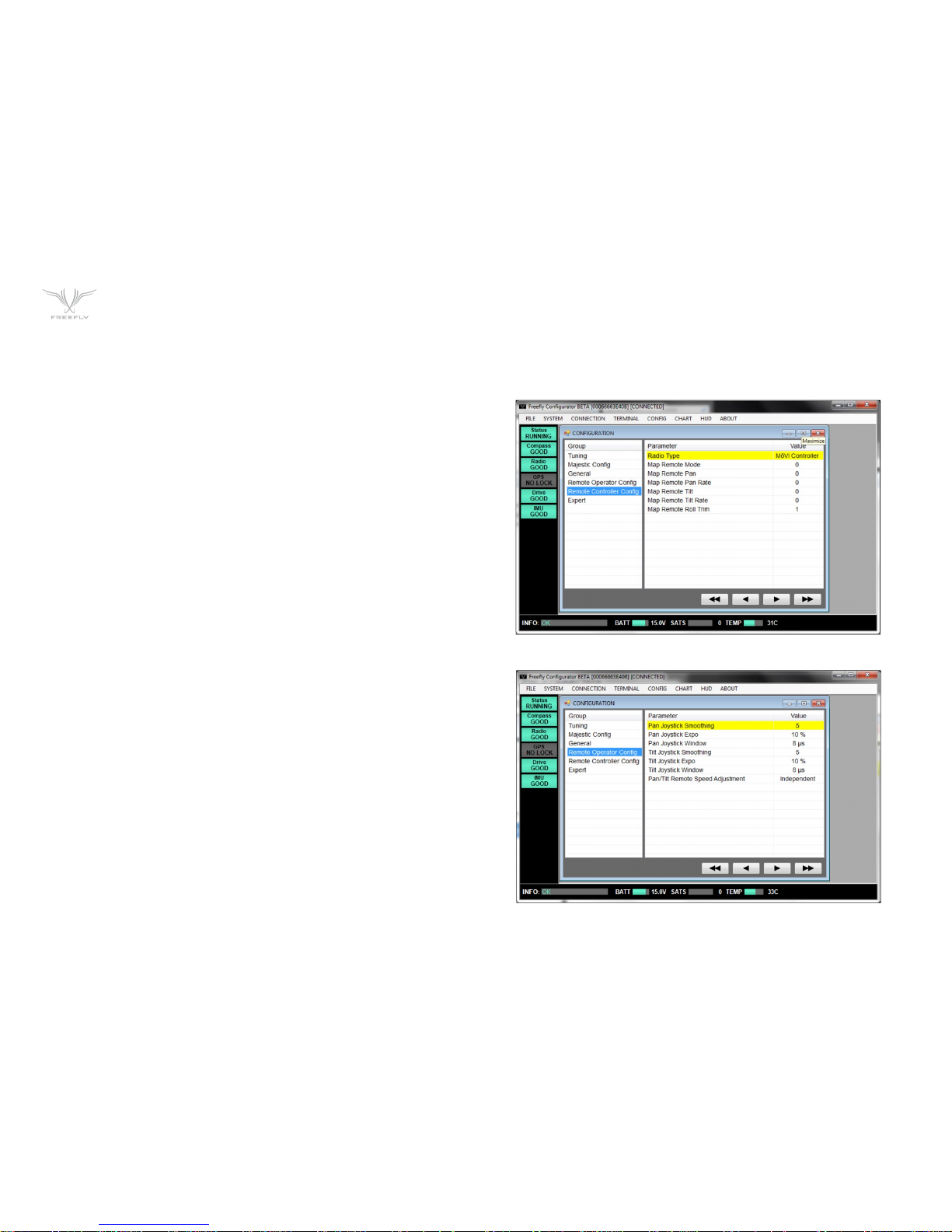
Once running firmware v3.08 or later, change the MōVI Radio Type from the
default (DSMX 2048) to MōVI Controller. This can be done from any of the
Freefly Configurator apps (PC, Mac, Android) in the Remote Controller Config
menu.
The values of the other parameters in this menu (Map Remote Mode, etc.) do
not matter for this Radio Type and can be left at
their defaults.
After installing the MōVI Controller Reciever (see Reciever Installation section
below, or the Quick Start Guide included in the package) and configuring the
MōVI Radio Type as above, the MōVI Controller is ready to send commands and
recieve data from the MōVI. As the Spektrum DX7/DX8 remote controller, the
feel of the joystick can be adjusted from the Remote Operator Config menu.
Page 6
P6
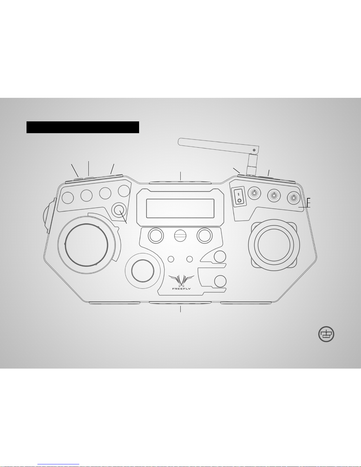
MōVI CONTROLLER LAYOUT
MōVI CONTROLLER // FULL CONTROLL AT YOUR FINGERS
12V DC Output
(2-Pin LEMO)
Pan
Speed
Tilt
Speed
Roll
Speed
Zoom
Speed
Power
Switch
User 3
Switch
Tilt Direction
Mode
Record
Start/Stop
Menu Select
Knob
Menu Set
Knob
User 1
Knob
User 2
Knob
Neck Strap
Eyelet
Roll Trim
Buttons
Focus Knob
Pan/Tilt
Joystick
Iris Knob
Zoom
Rocker
Dual Operator
Majestic Mode
Kill
13-20V DC Input
2x USB Ports
2.4 Ghz
Antenna
Monitor Mount / Tripod Mount
Tripod Mount
Menu Display
Auxiliary Data Port
(7-Pin LEMO)
Page 7
P7
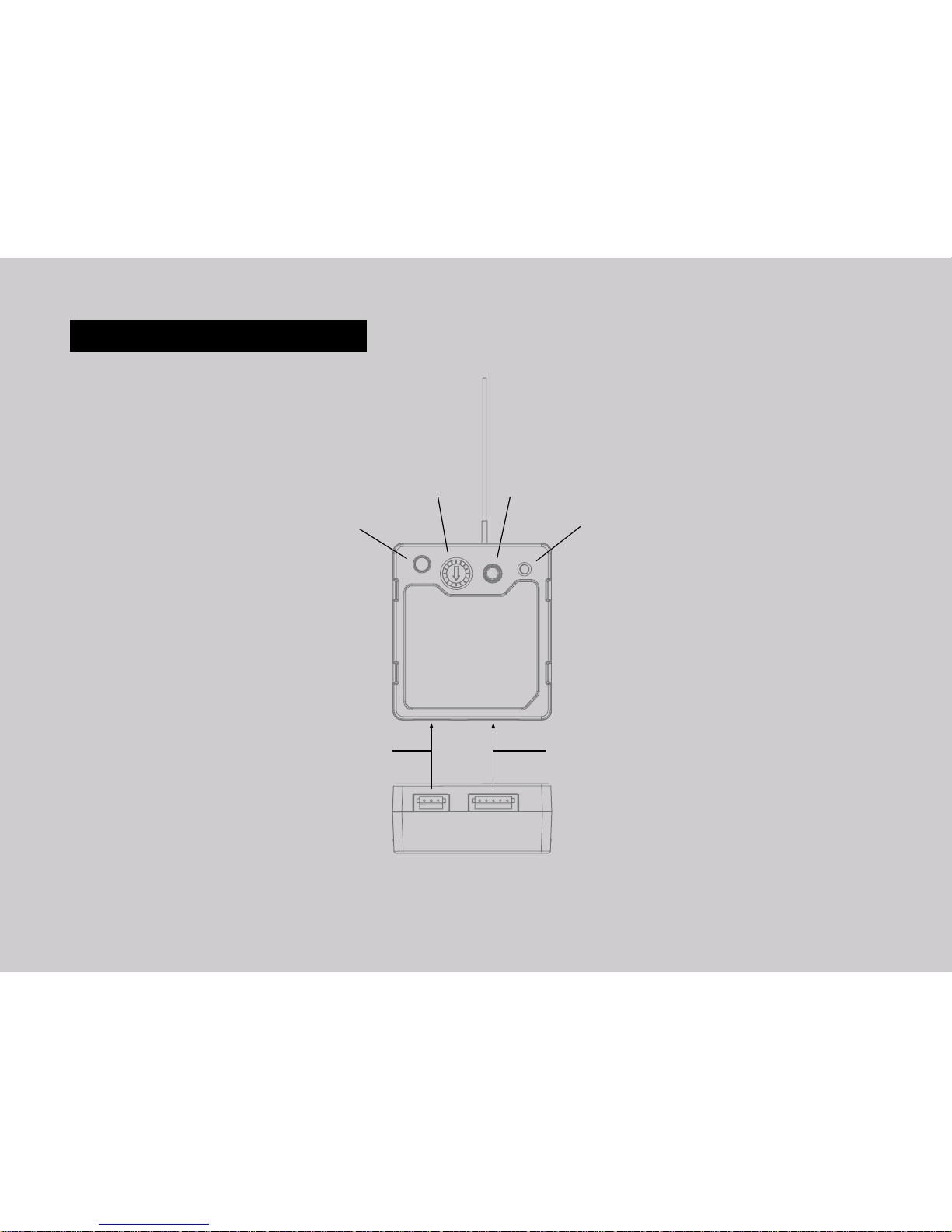
RECEIVER LAYOUT
2.4 Ghz Antenna
Channel Switch Bind Button
Firmware Update (FW) Button
5-Pin MōVI Data Port
3-Pin Spektrum Remote Port
Shutter/Record Output Port
Status LED
Page 8
P8
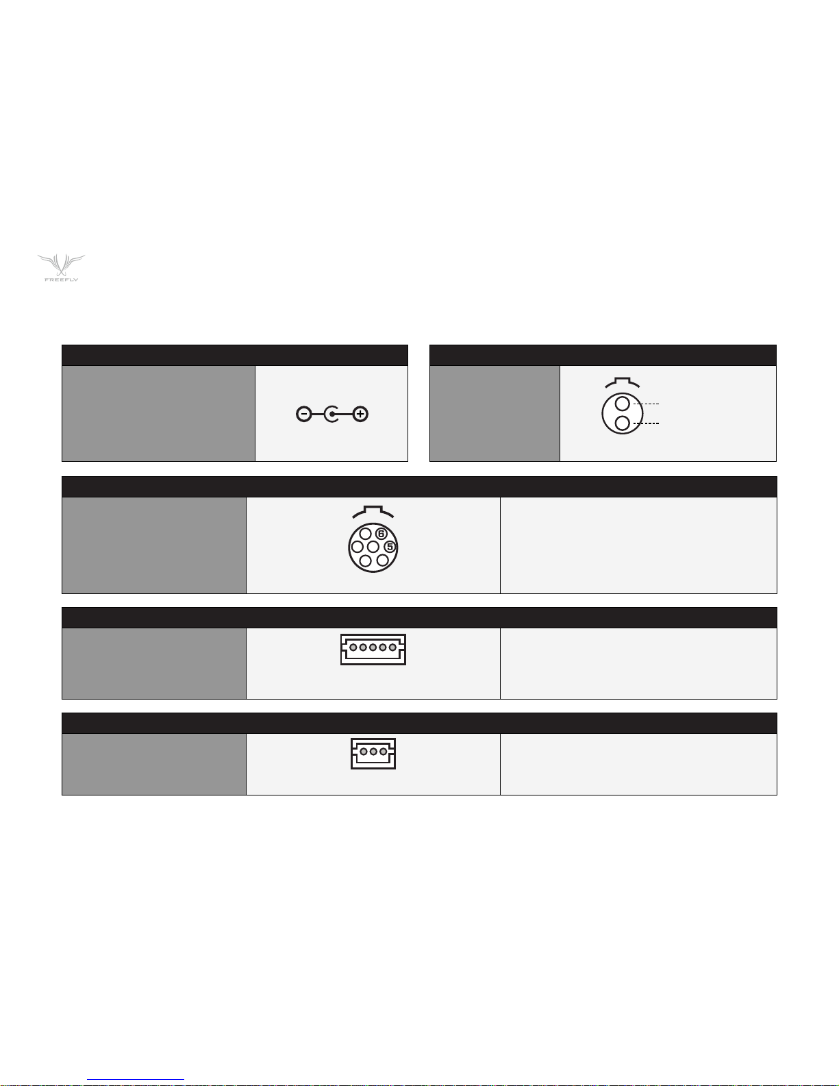
RECEIVER SPEKTRUM / RECORD OUTPUT PORT
3-pin JST ZH
ZHR-3
1 - 3.3V Input
2 - GNO
3 - Shutter/Record of Spektrum Date Out
(3.3V digital output)
RECEIVER DATA PORT
5-pin JST ZH
ZHR-5
1 - GND
2 - 5V Input
3 - Data In (3.3V digital input, 5V tolerant)
4 - Data Out (3.3V digital output)
5 - GPIO1
RECEIVER DATA PORT
7-pin LEMO
FGG.08.307.CLAD52
1 - GND
2 - 5V Output, 1A max.
3 - GPI01 (0.0V - 3.3V)
4 - GPI02 (0.0V - 3.3V)
5 - GPIO3 (0.0V - 3.3V)
6 - Auxillary Data Out (3.3V digital output)
7 - Auxillary Data In (3.3V digital input, 5V tolerent)
CONNECTORS AND PINOUTS
13-20V DC INPUT
5.5mm 0D
2.1mm ID Barrell Jack Connector
Center Positive
e.g. CUI Inc PP3-002A
12V DC OUTPUT
2-pin LEMO
FGG.08.302.CLAD52
(LOOKING IN TO RECEIVER SIDE CONNECTER)
(LOOKING IN TO CONTROLLER SIDE CONNECTER)
(LOOKING IN TO CONTROLLER
SIDE CONNECTER)
12V DC OUTPUT, 3A MAX
GNO
307
307
TYPE
TYPE
(LOOKING IN TO RECEIVER SIDE CONNECTER)
12345
123
1
7
2
4
3
1
2
Page 9
P9
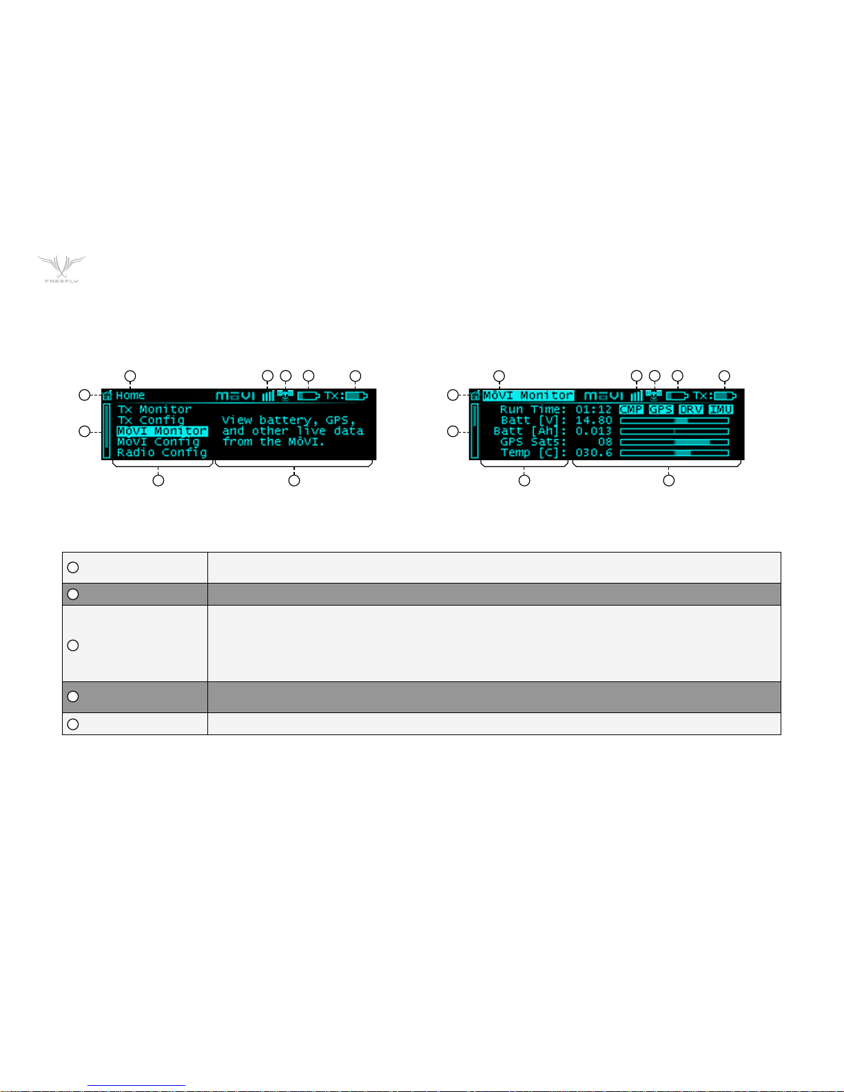
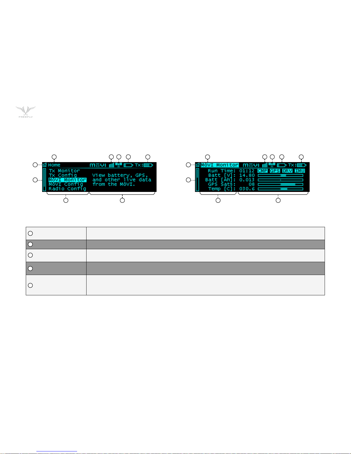
DISPLAY LAYOUT
HOME ICON
Return to the Home menu at any time by scrolling (with the Menu Select knob) to and clicking on the Home
icon in the top left corner of the display.
MENU TITLE The title of the currently active menu is displayed here.
MoVI Status
Booting
Error
Connected
When connected to a MōVI, this icon will display the MōVI Status:
The MōVI is starting up. Keep the camera stationary while this icon is displayed for the IMU to properly initilize.
The MōVI is connected, but an error has occured. Check the MōVI Monitor menu for more information on the error, or try
restarting the MōVI.
The MōVI is connected and running, and the MōVI Controller is receiving live telemetry.
GPS STATUS
When the MōVI acquires GPS lock, the GPS icon () is displayed and the GPS-based acceleration compensation
(to minimize horizon drift during high-acceleration movement) is active.
MōVI BATTERY LEVEL The state of charge of the MōVI battery. Check the MōVI Monitor menu for the exact battery voltage.
1
1 1
2
2 2
3
3 3
4
4 4
5
5 5
HOME SCREEN TYPICAL MENU SCREEN
6 6
8 8
9 9
107
Page 10
P10
DISPLAY LAYOUT
TRANSMITTER
BATTERY LEVEL
The state of charge of the MoVI Controller battery. See Power section for details on what batteries can be used with the MōVI
Controller.
MENU DESCRIPTION A brief description of each menu accessible from the Home menu.
MENU LIST
A list of menu items. The highest-level menus appear on the Home menu. Individual menu items appear within their respective
menu. Scroll through and select a menu item using the Menu SelectKnob.
SCROLL BAR
The scroll bar always appears on the left side of the display and shows the current scroll position, indicating if there are more
menu items above or below the ones currently displayed.
MENU ITEM DETAILS
Within a menu, details for each menu item are shown on the right side of the display. These include status indicators and
bar graphs for menu items that are read-only and adjustable values or options for menu items that can be modified. Use the
Menu Select Knob to change values or select options where applicable. Refer to the individual menu descriptions in the Menu
Structure section for details on each menu item.
6
7
8
9
10
HOME SCREEN TYPICAL MENU SCREEN
1 1
2 2
3 34 45 5
6 6
8 8
9 9
107
Page 11
P11
2
1
1
3
2
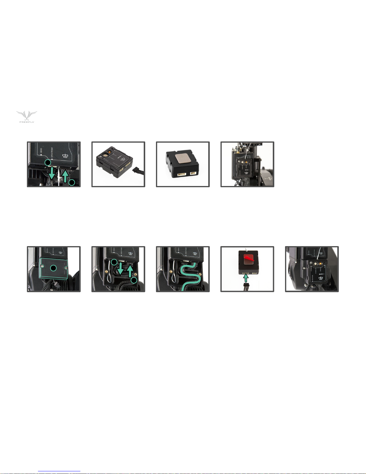
MōVI CONTROLLER RECEIVER INSTALLATION: M10
MōVI CONTROLLER RECEIVER INSTALLATION: M5 / M15
1. Remove the Spektrum
Receiever and 3-pin cable
(if applicable).
2. Plug shorter 5-pin cable
into MōVI Data port on
the Gimbal Controller.
3. Plug the other end of the
5-pin cable into the MōVI
Data port on the receiver.
4. Remove the adhesive
backing from the receiver.
5. Attach the Receiver
to the Gimbal Controller
shown.
1. Remove the Strain Relief
cover from the Gimbal
Controller.
2. Remove the Spektrum
Receiver and 3-pin cable
(if applicable).
3. Plug longer 5-pin cable
into MōVI Data port on
the Gimbal Controller.
4. Route the 5-pin cable
with the other wires
through the Strain Relief
track.
5. Replace the Strain Relief
cover.
6. Plug the other end of the
5-pin cable into the MōVI
Data port on the Receiver.
7. Remove adhesive backing
from the Receiver.
8. Attach the Receiver
to the Gimbal Controller
shown.
Page 12
P12
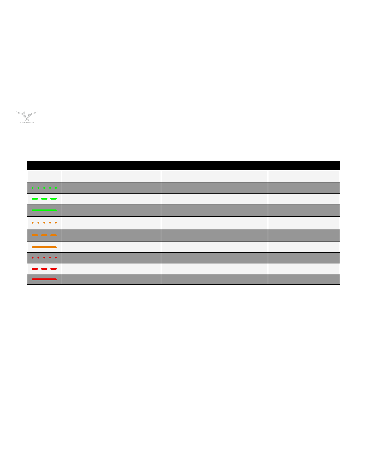
RECEIVER STATUS LED
The Receiver Status LED conveys information about the state of the radio link between the MōVI Controller and the MōVI.
LED CONDITION NORMAL OPERATION WHILE BINDING
OFF No Power. No Power.
FAST FLASHING GREEN Connection starting. Not used.
SLOW FLASHING GREEN Connection started. Waiting for data. Not used.
SOLID GREEN
Connected and receiving data
from MōVI Controller.
Bind successful.
FAST FLASHING ORANGE Not used.
Bind started, searching
for MōVI Controller.
SLOW FLASHING ORANGE Not used.
MōVI Controller found,
waiting for permission to bind.
SOLID ORANGE Not used. Not used.
FAST FLASHING RED Not used. Not used.
SLOW FLASHING RED Auto channel search failed. No MōVI Controller found.
SOLID RED Not used. Bind failed.
Page 13

P13
BINDING TO A NEW MōVI CONTROLLER RECEIVER
The MōVI Controller comes with a Receiver already bound to it and ready for communication with a MoVI. This MōVI Controller and Receiver form a bound pair. Only
that specific MōVI Controller can control that Receiver. However, it is possible to rebind the Receiver to a new MōVI Controller, or bind new Receivers to a single MōVI
Controller for working with multiple MōVI systems.
Ensure that the MōVI Controller and Receiver are both set to the same channel, or both set to auto-select (Channel 0)
Set the channel in Radio Config::Channel on the MōVI Controller.
Apply changes with Radio Config::Radio Action::Write.
Select the same channel on the Channel Switch at the Receiver.
Select a Device Group. Binding is specific to a Device Group; the receiver is joing the chosen group. See Radio Config menu description for more info.
Set the Device Group in Radio Config::Device Group.
Apply changes with Radio Config::Radio Action::Write.
Initiate Bind Mode on the MōVI Controller Receiver.
Press and hold the Bind button on the Receiver for at least two seconds. The Status LED will be fast-flashing orange to indicate the Bind Mode is active and it
is seeking a MōVI Controller with which to bind.
After a few seconds, the Status LED will change to slow-flashing orange to indicate that a MōVI Controller has been detected and the Receiver is requesting
permission to bind. A slow-flashing red Status LED at this point indicates that no MōVI Controller was detected.
Initiate Bind Mode on the MōVI Controller.
Allow the Receiver to bind by starting Bind Mode on the MōVI Controller with Radio Config::Radio Action::Bind.
After a few seconds, the Receiver will indicate successful binding with a solid green Status LED. A solid red Status LED indicates a bind failure.
Following a bind, the receiver will reset. During this time the Status LED will return to flashing green momentarily as the connection starts. After a few seconds,
the MōVI will be connected.
The receiver Status LED will return to solid green to indicate that it is receiving control data from the MōVI Controller.
The MoVI Controller will display a connection icon () and display MōVI battery voltage in the Status Bar to indicate that is is receiving data
from the MōVI.
If the bind process fails, try repeating Steps 1-5. For further troubleshooting steps, refer to the Troubleshooting section.
Page 14
P14
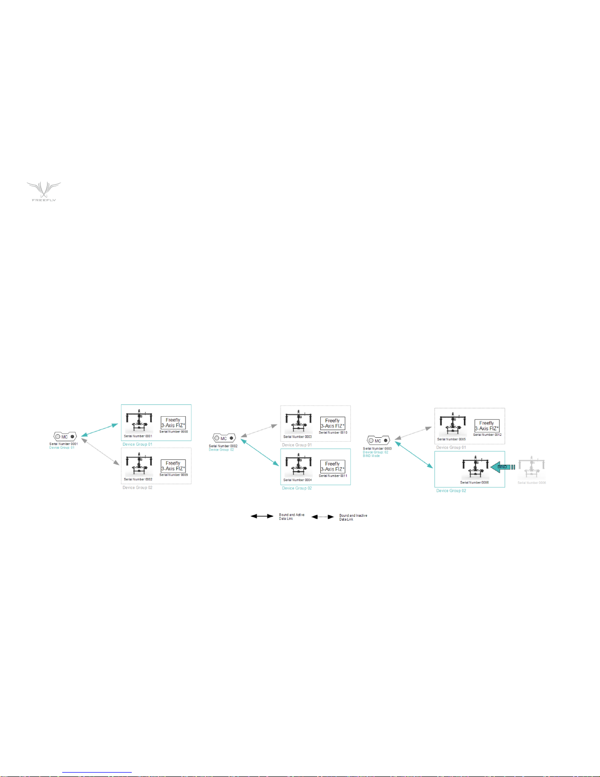
BINDING AND DEVICE GROUPS
The illustration below shows how a complex network of multiple MōVI Controllers, MoVIs, and Freefly 3-Axis FIZ Receivers* might be configured. Each Device Group
can consist of one of more MōVIs (with attached MoVI Controller Receivers) or Freefly 3-Axis FIZ Receivers. This allows a single MōVI Controller to control both the
MōVI and the Freefly 3-Axis FIZ Receiver on one radio link.
Additionally, the MōVI Controller can bind up to 16 Device Groups. This allows selection from multiple sets of prebound devices. Only one Device Group is active at any
given time. Devices in another Device Group will not be controlled, even if they are powered on and have been bound. The Device Group function is similar to "model
memory" on an RC transmitter.
Arrows indicate binds, which are potential data links for control and telemetry. It is not possible for an unbound MōVI Controller/Receiver pair to communicate. For
example, in the illustration below, MōVI Controller Serial Number 0001 cannot control MōVI Serial Number 0003, because they have not bound.
Binding is the act of joining a Device Group of one particular MōVI Controller. For example, setting MōVI Controller Serial Number 0003 to Device Group 02 and
binding MōVI Serial Number 0005 according to the bind process desribed above causes MōVI Serial Number 0005 to join that Device Group. After that, it can be
controlled by MōVI Controller Serial Number 0003 whenever Device Group 02 is selected.
Page 15

P15
POWER
DC INPUT:
The primary DC input is a 5.5mm O.D., 2.1mm I.D. center-positive barrel jack connecter located on the back of the MōVI Controller. It is designed for a 15V power
supply, but will accept voltages from 13V to 20V. It is reverse polarity protected up to 20V. However, supplying more than 20V will result in damage.
There are several battery options for powering the MōVI Controller. An optional IDX mounting plate can be fitted, which will supply power to the DC input from
standard V-Lock batteries and provides one additional D-Tap output. An optional overcurrent-protected MōVI battery (LiPo) cable is also available. The MōVI
Controller will go into low power sleep mode when the battery drains below 13V, but it is still important to turn off the power switch and remove the battery when
not in use.
12V DC OUTPUT:
When supplied with a 13-20V DC input, the MōVI Controller generates a regulated 12V output for powering auxilaries at up to 3A. The output is a 2-pin LEMO
connector with standard polarity. (Pin 1 / red dot / key is positive. Note: This is reversed from the polarity of the Teradek Bolt.) The mating connector is
FGG.0B.302.CLAD52.
USB:
The MōVI Controller USB ports are capable of supplying 5V at up to 2A for powering external devices such as wireless video receivers, tablets, or smartphones.
Note: Only the top USB port can be used for powering Apple devices.
The MōVI Controller can be powered at 5B through either of its USB ports. When powered by USB, the regulated 12V output will not be active. USB voltage may be
noisy and vary significantly from host device to host device. This can cause noise or drift on the joystick axes. Always power the controller through the primary DC
input when possible. Refer to the Tx Config menu description for tips on how to detect and remove joystick drift.
Note: Powering your MōVI Controller with both DC input and USB simultaneously will not cause any damage.
Page 16

P16
FOLLOW-FOCUS INTEGRATION
The MōVI Controller can integrate with wireless follow-focus systems from Redrock Micro and Hocus Products with an optional Auxiliary Transmitter. The Auxiliary
Transmitter uses the same hardware as the MōVI Controller Receiver and communicates directly with the follow-focus system. It connects to the Auxiliary Data Port
on the MōVI Controller. The range of the Auxiliary Transmitter is similar to that of the primary radio link to the MōVI (approx. 1200ft outdoor/line-of-sight).
REDROCK MICRO MICROREMOTE
To enable the Auxiliary Transmitter to communicate with a Redrock Micro microRemote Basestation:
1. Set the Auxiliary Transmitter to microRemote Auxiliary Transmitter mode by following the instructions in the Auxiliary Transmitter section.
2. Use the Channel Switch on the Auxiliary Transmitter to set the channel to be the same as that of the microRemote Basestation. This can and should
be set to a different channel than the primary radio link to the MōVI to prevent interference. See the channel mapping table in the Radio Config section.
3. Select "microRemote" in FIZ Config::System on the MōVI Controller.
Note: Only channels 1 through C are available. Channels 0, D, E, and F are reserved for low-power transmitters.
HOCUS PRODUCTS AXIS 1
To enable the Auxiliary Transmitter to communicate with a Hocus Pocus Axis 1 Digital Receiver:
1. Set the Auxiliary Transmitter to Axis 1 Auxiliary Transmitter Mode mode by following the instructions in the Auxiliary Transmitter section.
2. Use the Channel Switch on the Auxiliary Transmitter to set the channel to be the same as that of the Axis 1 Digital Receiver. This can and should be set to a
different channel than the primary radio link to the MōVI to prevent interference. See the channel mapping table in the Radio Config section.
3. Select "Axis 1" in FIZ Config::System on the MōVI Controller.
Note: Only channels 1 through C are available. Channels 0, D, E, and F are reserved for low-power transmitters.
Page 17

P17
MENU STRUCTURE
• TX ACTION: Load, Save, or Restore MōVI Controller Transmitter Configurations
SAVE
Save Tx Configuration to non-volatile (flash) memory from here.
Settings changes not saved before powering down the MōVI Controller will be lost.
LOAD
Load the most recently saved Tx Configuration from non-volatile (flash) memory. This can be useful for undoing changes made since the
last power up.
DEFAULT Temporarily restore the default factory Tx Configuration. Save this configuration permenantly using Tx Action::Save as described above.
RE-ZERO
Reset the center point of the Pan/Tilt Joystick and Zoom Rocker. These inputs are zeroed on start-up. Check the center points in the
Tx Monitor men. If pan, tilt, or zoom has more than 1-2% of offset when the joystick and zoom rocker are in their center positions, it can
create slow drift of the MōVI.
CALIBRATE Re-calibrate the end points of the Focus Knob. See Calibration section for calibration instructions.
• MAP ROLL INPUT:
• FOCUS DIRECTION:
• ZOOM DIRECTION:
• IRIS DIRECTION:
• PAN DIRECTION:
Assign an input (Zoom Rocker, Iris Knob, etc.) to control the MōVI Roll Axis
Reverse the direction of the Focus Knob input.
Reverse the direction of the Zoom Rocker input
Reverse the direction of the Iris Knob input.
Reverse the direction of the Pan/Tilt Joystick X-Axis (Pan). The Pan/Tilt Joystick Y-Axis (Tilt) can be reversed using the
Tilt Direction Switch.
HOME
The home menu is the starting point for navigating through other MōVI Controller menus. You can always return to the Home menu by scrolling to and clicking the
Home icon in the top-left corner of the display.
TX MONITOR
The transmitter (Tx) Monitor menu displays information about the transmitted user inputs. The Pan/Tilt Joystick, Focus Wheel, Zoom Rocker, Iris Knob, Record Button,
and other knobs and switches report their position in this menu. This information can be useful for holding consistent pan, tilt, or zoom rates.
TX CONFIG
User inputs and the MōVI Controller operation can be customized from the Tx Config menu:
Page 18

P18
• RECORD TYPE: Change the shutter/record output on the MoVI Controller Receiver.
MOMENTARY The Shutter/Record Output is active only while the Record Start/Stop Button is pressed.
TOGGLE The Shutter/Record Output switches between active and inactive each time the Record Start/Stop Button is pressed.
• RECORD POLARITY: Change the active state of the Shutter/Record Output signal from the MoVI Controller Receiver.
NORMAL The Shutter/Record Output is active high (3.3V digital output).
REVERSE
The Shutter/Record Output active low (0.0V digital output).
• TILT REV Function: Configure the function of the TILT REV switch center position.
NORMAL The Center position is the same as the Up position (TILT FWD).
REVERSE The Center position disables the Tilt Axis.
• USER 3 Function:
• USER 1 Function:
• USER 2 Function:
Assign a function to the USER 3 switch. See User Functions table below.
Assign a function to the USER 1 knob. See User Function table below. The USER 1 function assignment has priority over
USER 2 and USER 3.
Assign a function to the USER 2 knob. See User Function table below. The USER 2 function assignment has priority
over USER 3.
Page 19

P19
USER FUNCTION DESCRIPTION USER 1 USER 2 USER 3 NOTES
None Default Default Default
Pan Dir Reverse Pan/Tilt Joystick X-Axis (Pan). Yes Yes Yes Threshold is 50% for USER 1 and USER 2.
Focus Dir Reverse Focus Knob input. Yes Yes Yes Threshold is 50% for USER 1 and USER 2.
Zoom Dir Reverse Zoom Rocker input. Yes Yes Yes Threshold is 50% for USER 1 and USER 2.
Iris Dir Reverse Iris Knob input. Yes Yes Yes Threshold is 50% for USER 1 and USER 2.
Mode Change MoVI Mode: Kill, Majestic, Dual Operator. Yes Yes Yes Disables the dedicated Mode Switch.
Pan Speed Adjust maximum Pan Speed. Yes Yes No Disables the dedicated Pan Speed Knob.
Tilt Speed Adjust maximum Tilt Speed. Yes Yes No Disables the dedicated Tilt Speed Knob.
Roll Speed Adjust maximum Roll Speed. Ye s Yes No Disables the dedicated Roll Speed Knob.
Zoom Speed Adjust maximum Zoom Speed. Yes Yes No Disables the dedicated Zoom Speed Knob.
When a knob is used to control axis direction, forward is defined as >50% (clockwise) and reverse is defined as <50% (counter clockwise) rotation.
Page 20

P20
MōVI MONITOR
Live telemetry from the MōVI is available in this menu. The first line displays MōVI run time since power-up, as well as the status of important MōVI systems:
Compass (CMP), Global Positioning System (GPS), Motor Drive (DRV), and Inertial Measurement Unit (IMU).
The Compass (CMP) and Global Positioning System (GPS) are used to minimize the effect of high acceleration on the MōVI’s tilt and roll axis stabilization. In indoor
environments, they may not be available, but the MōVI will still operate.
The Motor Drive (DRV) and Inertial Measurement Unit (IMU) are critical systems and the MōVI will not operate without them. If DRV or IMU is not active, the following
quick troubleshooting steps may help:
+ Motor Drive (DRV) Errors: Check for unplugged wires at the Motor Drive (MōVI M10). Check for wire damage in general.
+ Inertial Measurement Unit (IMU) Errors: The IMU may fail to start properly if the MōVI is moving during startup. Try rebooting the MōVI while
stationary. If this fails, check for an unplugged wire between the IMU and the Gimbal Controller, or physical damage to the IMU.
Other telemetry values in this menu provide information about MōVI status and performance:
+ Batt [V]: The exact MōVI battery voltage is provided here. (An approximate fuel gauge is always available in the status bar.)
+ Batt [Ah]: An estimate of the battery capacity used since startup of the MōVI. Consult the battery labeling for the nominal full-charge capacity.
+ GPS Sats: The number of GPS satellite links acquired. A minimum of six is required for the MōVI to utilize GPS-based acceleration compensation.
Not applicable in indoor environments.
+ Temp [C]: The temperature of the MōVI processor. (Typical values are under 50-60ºC.)
+ CPU [%]: The MōVI processor utilization. (Typical values are under 60-70%.)
+ Tilt/Roll/Pan [deg]: The physical angle of each MōVI axis, referenced to the outside world. This can be useful for moving to exact positions, such as
looking straight down (Tilt -90º).
+ Tilt/Roll/Pan Motor: The amount of motor torque used on each axis. This can be helpful during balancing: A well-balanced MōVI should show less
than 3% torque on all three motors in any camera or handle position.
Page 21
P21
• SYSTEM OPTIONS
SAVE SETTINGS
Save MōVI configuration to non-volatile (long-term) memory from here. Settings changes not saved before powering down or rebooting
the MōVI will be lost.
REBOOT MōVI Reinitialize the MōVI. This can be useful for clearing any Errors that occur during MōVI start-up.
• TILT/ROLL/PAN
STIFFNESS
• AUTO TUNE
• AUTO TUNE
SET (%):
• GYRO/OUTPUT
FILTER
These settings control how much the motors are used to stabilize the camera on each axis. For best performance, each Stiffness value
should be as high as possible without causing oscillation on its axis. Generally, heavier cameras allow for higher Stiffness settings. Reverse
the direction of the Focus Knob input.
The MōVI is capable of automatically adjusting Stiffness settings once a camera payload has been attached
and balanced. Select “Start” to begin the process.
The Auto Tune process adjusts the Stiffness settings until oscillation is detected, then sets the final values to a fraction of the value at
the onset of oscillation. This parameter adjusts the safety margin used. 50% is a good value for most applications (50% --MōVI M10 and
70% --MōVI M5) . A higher value may result in better performance. A lower value allows for more flexibility in adjusting focal length, changing
lenses, or adding accessories without retuning.
(Expert Settings) These settings adjust the strength of the filters applied to the MōVI’s gyro inputs and motor outputs, respectively. If
the MōVI is experiencing oscillations that cannot be corrected by adjusting Stiffness settings, you can use the filters to further tune the
gimbal and remove oscillations. As a general rule, if the oscillations are fast and rough in nature (buzzing/vibration), try increasing the filter
values. If the oscillations are slow and smooth in nature (rocking), try decreasing the filter values. The following factory-default values work
well in most cases:
GYRO FILTER OUTPUT FILTER
MōVI M5 3 3
MōVI M10 5 5
MōVI CONFIG
Page 22

P22
• MAJESTIC MODE: This configures the MōVI's single-operator mode, called Majestic Mode, and is enabled using the MODE switch (M, center position,
for Majestic) or by turning off the MōVI Controller. There are two Majestic Mode options:
TILT LOCK Allow the tilt axis to be positioned by hand, then holds that angle.
TILT ON Allow the tilt axis to be controlled by pointing the MōVI handles.
• MAJESTIC PAN/
TILT SMOOTHING
• MAJESTIC PAN/
TILT WINDOW
In Majestic Mode, pan (and tilt, if enabled) are controlled by pointing the MōVI handles. An adjustable amount of smoothing is added to
the camera movements here. Higher values will give smoother pan and tilt movements, but more lag. Lower values will force the camera
to follow the handles more closely.
In order to eliminate unintentional pan/tilt movements and maintain stability, an adjustable window can be set within which Majestic Mode
will ignore MōVI handle movements. A lower window will cause the camera to follow the handles more accurately, for slow, precise shots. A
higher window will allow for handle movement without affecting stability, for dynamic running or jumping shots.
To access the full range of MōVI configuration settings, use the MōVI Configurator app available for PC, Mac, and Android at:
http://www.freeflysystems.com/.
For a more detailed description of each MōVI configuration parameter, refer to the MōVI manuals available at:
http://www.freeflysystems.com/media/instruction-manuals.php.
• RADIO ACTIONS: Select an action to perform for configuring the primary radio. Start the action by clicking the Menu Set knob. Note: These actions will
momentarily halt MōVI control and telemetry while the radio is being configured. The MōVI may briefly return to Majestic Mode during
this time.
READ Read the current Channel, Device Group, and Power Level from the radi.
WRITE Write the modified Channel, Device Group, and Power Level to the radio.
BIND
Add a new receiver to the current Device Group. This will allow the MōVI Controller to communicate with the new Receiver. See Binding to
a New MōVI Controller Receiver above.
RADIO CONFIG
Settings for configuring the primary 2.4GHz radio transceiver are located here. You can also bind to a new Receiver in this menu.
Page 23

P23
• CHANNEL The channel setting determines the physical RF channel used by the MōVI Controller’s primary radio link. One of twelve channels in the
2.4GHz band can be chosen manually, or choose 0 (Automatic) to allow the MōVI Controller to automatically select the clearest channel at
startup. The channel selected must match the channel on the MōVI Controller Receiver.
MOVI CHANNEL CENTER FREQUENCY [GHZ] REDROCK MICRO MICROREMOTE CHANNEL HOCUS PRODUCTS AXIS 1 CHANNEL
0 (Auto) Auto-Selecting N/A N /A
1 2,410 1 1
2 2,415 2 2
3 2,420 3 3
4 2,435 4 4
5 2,430 5 5
6 2,435 6 6
7 2,440 7 7
8 2,445 8 8
9 2,450 9 9
A 2,455 A 10
B 2,460 B 11
C 2,465 C 12
D N/A N/A N /A
E N /A N/A N /A
F N /A N/A N /A
These channels are reserved for low-power transmitters and are not available on the MōVI Controller.
• DEVICE GROUP
• POWER LEVEL
The MōVI Controller can store up to 16 Device Groups. (This is akin to “model memory” on a standard RC transmitter.) Each device group
can have one or more MōVI Controller Receivers bound to it. This can be useful for selecting between multiple MōVI systems that are on at
the same time. For simple single MōVI use, the Device Group can be left at the default setting (0).
Configure the power level (from 10-18dBm) to ensure compliance with local RF regulations. Radios shipped outside of North America have
only the EU (10dBm) option available. The range of the link has been tested at up to 300m line-of-sight at EU (10dBm) power.
Page 24

P24
• RADIO MODE
TILT LOCK Allow the tilt axis to be positioned by hand, then holds that angle.
TILT ON Allow the tilt axis to be controlled by pointing the MōVI handles.
TETHER/RX FW
In this mode, the MōVI Controller relays raw data between the Receiver and a host computer via USB. This can be used to control the
MoVI from a computer interface, or to update the Receiver firmware.
• SYSTEM
• INPUT
Choose between supported wireless follow-focus systems. See Follow-Focus Integration section for more details on supported systems.
Choose None to disable the Auxiliary Transmitter and allow follow-focus control from a separate handset.
Choose which user input axis is active on the Auxiliary Transmitter output. The Focus Knob, Zoom Rocker, and Iris Knob can each be
optionally selected for output to a single-axis system. For direction reversal, see the Tx Config menu section above.
FIZ CONFIG
Configure the operation of wireless Focus-Iris-Zoom (FIZ) systems in this menu. For more information on supported systems, see the Follow-Focus Integration
section.
To save FIZ configuration settings, use Tx Config::Tx Action::Save.
SPEKTRUM DSMX 2048 CHANNEL MŌVI CONTROLLER FUNCTION
Aileron Pan
Elevator Tilt
Throttle Pan Speed
Rudder Roll Trim
Gear TK Rec Start/Stop
Aux 1 TK Mode Switch (Dual, Majestic, Kill)
Aux 2 Tilt Speed
Page 25

P25
HARDWARE
MOUNTING PLATES
There are a series of mounting plates along the front of the controller with 1/4-20 threaded holes. To mount the MōVI Controller to a
tripod using these plates, attach the tripod plate to any of the 1/4-20 threaded holes and rotate the tripod head to the desired angle.
HEAT SINK
The heat sink located on the back of the controller has a 1/4-20 thread that can be used to mount the MōVI Controller to a tripod when
an IDX plate is not attached.
TRIPOD ADAPTER
PLATE
The MōVI Controller comes with a tripod mounting plate installed. The tripod mounting plate is attached to the rear mounting plate and
has both 1/4-20 and 3/8-16 tapped holes for mounting to a tripod.
+ Insert the 1/4-20 x 1.25” set screw through the top, center hole of the tripod adapter plate into the mounting plate located on the back of the controller.
+ Tighten the set screw using a 1/8” or 3mm hex driver.
+ Make sure the knurled set screw on the Giottos mini ballhead mount is tight, and thread the monitor onto the 1/4-20 thread on the mini ballhead mount.
+ With the screen attached and the knurled set screw on the Giottos mini ballhead still tight, thread the mini ballhead mount onto the 1/4-20 set screw.
+ To adjust the screen position, loosen the knurled set screw and rotate the mini ballhead housing and adjust the monitor angleuntil the monitor is in the
correct orientation.
+ Tighten knurled set screw to lock monitor in place.
MOUNTING TO TRIPOD
There are several options for mounting a tripod on the MoVI Controller.
ATTACHING MONITOR
The MōVI Controller comes with a Giottos mini ballhead mount and set screw for mounting a monitor. To install a monitor:
Page 26

P26
TROUBLESHOOTING
SYMPTOM POSSIBLE CAUSE SOLUTION
Transmitter will not power on. (No display) Incompatible power supply or low battery.
Ensure that the voltage supplied to the MōVI
Controller is 13.0-20.0V (or 4.5-5.5V for USB power
input). If using a battery, check that the battery is
charged.
Cannot connect to a MōVI.
Receiver Status LED:
(None)
The Receiver is not powered.
Make sure the Receiver is installed correctly
and the MōVI is powered on. See installation
instructions in the Receiver section.
Cannot connect to a MōVI.
Receiver Status LED:
(Fast-Flashing Green)
Unsupported MōVI firmware or incorrect radio
type in MōVI Configurator.
Update to MōVI firmware v3.08 or later and
configure theRadio Type to “FTX” in the MōVI
Configurator App.
The connection is still starting.
Wait for the connection to be established:
Channel 1 thru C: < 5 seconds
Channel 0 (Auto): < 15 seconds
The MōVI Controller and Receiver are on different
channels.
Set the Receiver to the same channel as the
MōVI Controller (Radio Config::Channel), or to
Channel 0 (Auto).
The connection is still starting.
Change the MōVI Controller Device Group (Radio
Config::Device Group) to the one into which the
Receiver was bound. (The default Device Group is
00.)
The Receiver is new and/or not bound to the MōVI
Controller.
Follow the instructions for binding a new Receiver
in the Receiver section.
Can control a MōVI, but the data/telemetry is not
present or corrupted. Receiver Status LED :
(Solid Green)
Multiple bound MōVIs are on at the same time.
Turn off MōVIs that are bound to this MōVI
Controller but not in use, or re-bind the other
MōVIs into different Device Groups.
Page 27

P27
SYMPTOM POSSIBLE CAUSE SOLUTION
Bind Failed. Receiver Status LED:
(Slow-Flashing Red) OR
MōVI Controller was not detected.
Make sure the MōVI Controller is powered on and
in range. Turn off any other MōVI Controller that
might be in range.
(Solid Red) MōVI Controller did not allow binding.
Use Radio Config::Radio Action::Bind to permit
binding after the Receiver Status LED changes to
slow-flashing orange:
(See binding instructions in the Receiver section.)
A user input (e.g. Pan Speed Knob, Mode Switch)
is not working.
The input has been remapped in Tx Config.
Check the assignment of USER 1, USER 2, and
USER 3 in the Tx Config menu to see if the user
input in question has been remapped to one of
these.
The input is broken/damaged.
Many user inputs can be remapped. For example,
the Mode Switch can be remapped to the USER 3
switch. See the Tx Config menu section for more
information.
The Pan/Tilt Axes are not working Pan/Tilt Speeds are at their minimum settings. Increase these setting using the Speed Knobs.
The MōVI is in Majestic Mode. Change to Dual Op. mode using the Mode Switch.
Page 28

P28
AUXILIARY TRANSMITTER
The MōVI Controller Receiver can optionally be used as an Auxiliary Transmitter for controlling third-party wireless follow-focus systems. For more information on
supported systems, see the Follow-Focus Integration section. To change modes:
1 - Move the Receiver Channel Switch to the position indicated in the table below.
2 - Hold down the FW Button and then press the Bind Button once.
3 - The new mode will be active after the next power cycle.
Auxiliary Transmitters and Auxiliary Data Port connector are sold separately.
MODE CONNECTS TO DESCRIPTION
MōVI Controller Receiver Status LED:
(Solid Green)
Set Channel: 0 - C
Press Bind Button while holding down FW Button.
MōVI Gimbal Controller, MōVI Data Port.
(See Receiver Installation section.)
This is the normal operating mode for two-way
communication from the MōVI Controller to the
MōVI. The Receiver thatcomes included with the
MōVI Controller is in this mode by default.
microRemote Auxiliary Transmitter Status LED:
(Slow-flashing green/orange)
Set Channel: D
Press Bind Button while holding down FW Button.
MōVI Controller Auxiliary Data Port.
In this mode, the MōVI Controller Receiver acts
as an Auxiliary Transmitter for sending commands
to a Redrock Micro microRemote Basestation.
Axis 1 Auxiliary Transmitter Status LED:
(Fast-flashing green/orange)
Set Channel: E
Press Bind Button while holding down FW Button.
MōVI Controller Auxiliary Data Port.
In this mode, the MōVI Controller Receiver acts
as an Auxiliary Transmitter for sending commands
to a Hocus Products Axis 1 Digital Receiver.
Page 29

P29
The MōVI Controller Receiver included with the MōVI Controller is configured in MōVI Controller Receiver mode by default. It can be changed to an Auxiliary
Transmitter mode if necessary by following the instructions above.
Auxiliary Transmitters purchased separately for follow-focus integration will be preconfigured in either microRemote Auxiliary Transmitter mode or Axis 1 Auxiliary
Transmitter mode depending on the option selected at purchase. However, they can be changed to any other mode at a later date by following the instructions
above.
FIRMWARE UPDATE
The MōVI Controller firmware can be updated using the included USB A-A cable. The latest firmware, release notes, and update instructions are available at
www.freeflysystems.com.
CALIBRATION
User inputs can be recalibrated to fine-tune the center and end-points. Recalibration is not usually necessary, but can be done through Tx Config::Tx Actions::-
Calibrate. The following table lists inputs that may be recalibrate by the user, as well as the calibration triggers for each.
Verify that the focus knob end points are correct by viewing the Focus input in the Tx Config menu. It should move from 0.0 to 100.0 over the full range of theknob,
with no dead spots or jumps. To save the new focus knob end-point calibration, use Tx Config::Tx Action::Save.
Other inputs are factory-calibrated and cannot be changed at this time.
USER INPUT CALIBRATION TRIGGER
Focus Knob Right End Point
User 3 Switch Up, then press Menu Set while in
Tx Config::Tx Actions::Calibrate
Focus Knob Left End Point
User 3 Switch Down, then press Menu Set while in
Tx Config::Tx Actions::Calibrate
Page 30

P30
CERTIFICATIONS
The MōVI Controller transmitter and receiver contain radio modules and antennas that are certified for use internationally. The following agency certifications apply:
FCC
Contains FCC ID: OUR-XBEEPRO
CANADA (IC)
Contains Model XBee-PRO Radio, IC: 4214A-XBEEPRO
EUROPSE (ETSI)
Radio module conforms to CE requirements.
Restrictions: When operating in Europe, XBee-PRO 802.15.4 modules must operate at or below a transmit power output level of 10dBm (Power Level 0).
JAPAN
ID: 005NYCA0378
Restrictions: Maximum transmit power output level of 10dBm (Power Level 0).
Page 31

P31
WEDGE
Page 32

P32
WEDGE LENS CONTROL SYSTEM
The Wedge is the perfect lens control system for use with MōVI.
Top Features
1. Designed for MōVI and ALTA.
2. The smallest and lightest 3 axis standard lens controller available.
3. 3 Axis lens mapping for physical unit display of focal distance, aperture and focal length.
4. Compatible with the majority of industry standard lens motors.
5. Full remote control and configuration.
6. Integrated MōVI top rail universal mount.
7. Manual and automatic calibration with torque sensing.
8. Configurable sub-range limits, dampening, speed, torque and focus scale stretching.
9. High powered radio for long range.
10. Camera control for most common cameras including Lanc and Sony Multiterminal.
11. Highly expandable architecture.
GENERAL OPERATION
The Wedge controls three industry standard lens motors, (one each for Focus, Iris and Zoom) and control of Run/Stop and other camera features remotely using the
MōVI Controller. All configuration and control other than radio channel setting and binding is remotely controlled.
STATUS LED
Cycles through color combination on startup. During normal operation, it displays the same colors as the MōVI Receiver.
Page 33

P33
FIZ (FOCUS, IRIS, ZOOM) MAIN SCREEN WITH PERCENTAGE SCALES SCREEN WITH 3 AXIS LENS MAPPING ACTIVE
MENU STRUCTURE
The Wedge is controlled and configured by several dedicated MoVI Controller Screens described below. Primary navigation and control is achieved by scrolling and
pressing the MENU and SET buttons.
FIZ MAIN
This is the typical “Home” screen for FIZ multi-axis operations. It shows the positions of all axes and provides access to the majority of common control commands.
• Positions of Each Axis: Displayed in Percent or, when a Lens Map is selected, physical units. Units are changeable on the FIZ Config. Screen.
• Z-Spd: Zoom speed scaling.
• CAM (Camera Status): STBY/REC. This is the status of the output for simple output type run stop camera interfaces, (RED EPIC, RED ONE, ARRI RS) or status from
the camera for serial interfaces (LANC, Sony MT, etc).
• Limits: Allows setup of motor range limiting. Move the motor to the position you would like the first limit to be set. Highlight the limits field. Press the SET button
and keep it pressed. Move the knob to the second limit. Release the SET button. The entire range of the control knob will now cause motor motion in the limited
range. Momentarily press and release the button again to turn off the limits.Z-Spd: (Zoom Speed) Zoom Speed Scaling.
• Lock: With this field selected, pressing the SET button locks the position so that knob movement doesn't move the motor. Press the SET button again to unlock.
• CAL: With this field selected, pressing the SET button requests an auto calibration to be performed on each axis.
• RESET: Clears Faults on any faulted axes. Axis reset to the un-calibrated state.
• Lens: The focal length of the currently selected lens.
Page 34

P34
FOCUS DETAIL SCREEN,
AUTO-CALIBRATION TORQUE SENSING
FOCUS DETAIL SCREEN,
AUTO-CALIBRATION FINDING LIMIT 1
FOCUS DETAIL SCREEN,
AUTO-CALIBRATION FINDING LIMIT 1
FIZ AXIS DETAIL
This screen shows detailed information for a single axis at a time. Each Axis can be viewed using this screen.
• F/I/Z Letter: Highlight this field and scroll the SET button to change the axis for which you want to view the details for CAM: (Camera Status) STBY/REC. This is the
status of the output for simple output type run stop camera interfaces, (RED EPIC, RED ONE, ARRI RS) or status from the camera for serial interfaces (LANC, Sony
MT, etc).
• Position: Units are changeable on the FIZ General Cfg Screen. A lens must be selected for real units to be displayed. The position is also indicated by the bar scale.
• CAL: Scrolling the SET button selects AUTO (AT) or MANUAL (MN) calibration mode. Pressing the SET button begins calibration. See the “How To” sections for
calibration sequences.
• Lock: First press locks position movement on the axis. Second press unlocks.
• LANC +/-: Pressing the SET button on these Icons commands movement of the lens axis when connected to supported cameras/lenses via LANC connection to
camera. Scrolling the SET button while either + or – is highlighted moves the axis one increment.
• Limits: Same as above. Also, the minimum and maximum range selected will be displayed under the progress bar in the selected axis units, and the bar is filled in
where the range limits are.
• STAT: Shows which state the selected axis is currently in. Typically this is used to view the steps the axis is in during homing. The following are the states:
• Uncalibrated
• Moving to Command Position
• Calibrated
• Auto Cal Sensing Torque
• Auto Cal Finding Limit 1
• Auto Cal Finding Limit 1
• Manual Cal Set Min Limit
• Manual Cal Set Max Limit
• Faulted
Page 35

P35
WEDGE CONFIGURATION SCREEN 1 WEDGE CONFIGURATION SCREEN 2
FIZ CONFIG
This screen is used for general configuration of the Wedge. It contains settings that are axis-specific but not common to all axes, and other non-axis related settings.
SETTINGS
ACTION
Scrolling SET allows selection of Load Defaults/Load Saved/Save. Pressing SET performs the requested option. This only affects settings
that are persistent and not state dependent. The units and scaling are not persistent.
CAMERA TYPE
This selects the type of camera that the FIZ is connected to. Note that the proper cable must be used to control the camera, and this
setting must be set correctly.
FOCUS SCALE
Linear/Stretched. Setting this to Stretched causes more of the focus knob travel to be used in the longer focal distance range where the
scale gets compressed. This allows greater fidelity of focal point as the focal distance grows.
FOCUS STD/
METRIC UNIT
Selects between Feet/Inch or Meters to be used for focus distance measurements when the selected units for the focus axis is
Distance.
LENS UNIT FOCUS
(PERCENT/
DISTANCE)
Setting this to distance shows the Focus position in physical units or percent. A lens must be selected to show physical units.
LENS UNITS IRIS
(PERCENT/FSTOP)
Setting this to distance shows the Focus position in physical units or percent. A lens must be selected to show physical units.
LENS UNITS ZOOM
(PERCENT/FOCAL
LENGTH)
Setting this to Focal Length shows the Zoom position in physical units or percent. A lens must be selected to show physical units.
Page 36

P36
FIZ CONFIG MENU 1 FIZ CONFIG MENU 2
FIZ AXIS CFG
This screen allows configuration of axis specific settings that are present on each axis, but allows setting them independently. The Axis is selected using the 1st field.
The rest of the settings then reflect the setting of the selected axis.
AXIS SELECT Scrolling allows selection of Focus/Iris/Zoom.
SETTINGS ACTION Scrolling SET allows selection of Load Defaults/Load Saved/Save. Pressing SET performs the requested option.
MOTOR MODEL
Sets control loop gains, fault settings and other settings that are specific to the motor. These are relatively small adjustments and
motors generally work independent of this setting, but will not be optimized and protected as well.
DAMPENING Changes the amount of low pass filtering of the input control knob or other interface.
KNOB DIRECTION
Changes the direction that the Knob (or other control interface) is interpreted. It can be used in conjunction with the Motor Direction
setting to allow the preferred control interface direction while still ensuring the mapped units are correct. This setting is not persistent.
MOTOR DIRECTION
Normal/Reverse. Changes motor direction. This is especially important when using a mapped lens. If the lens is moving opposite of the
physical units displayed on the screen, setting this to reverse will cause the motor to move with the units. This setting is persistent and
is stored on the Wedge.
TORQUE LIMIT Changes the amount of maximum current allowed. Note that these are relative current settings, and may be different between motors.
SPEED
(SLEW RATE) LIMIT
This changes the maximum speed that the motor can reach. It provides a way to smoothly limit the motor speed if needed to ensure
smooth operation and limited stress on the lens.
CONTROL INPUT
(FOCUS/IRIS/
ZOOM)
This allows changing the control input setting fo each axis to be changed. The following are the traditional inputs.
Focus: Large Knob
Iris: Small Knob
Zoom: Rocker Swith
Focus: Large Knob
Iris: Small Knob
Zoom: Rocker Switch
Page 37

P37
LENS MAPPING
The MōVI Controller has the ability to save a set of information about lenses that allows a lenses actual physical units to be displayed instead of a simple percentage
of travel. This is called lens mapping, as it requires the user to save a set of lens position points along the travel of each axis. These position points are used by
sophisticated curve fitting functions to accurately calculate the lenses’ values in between, by interpolating these points anywhere in the lenses axis travel ranges.
SELECTABLE UNITS FOR EACH AXIS
FOCUS Percentage of Travel
Focal Distance (Ft. + Inches or Meters)
IRIS Percentage of Travel
Aperture (F/T Stops)
ZOOM Percentage of Travel
Focal Length (mm)
Page 38

P38
LENS MAP FILE
Lens files contain data that is used to identify and map the lens. The files are stored in a folder-like organization consisting of:
/ Manufacturer / Model Name / Serial Number
The following is the data contained in each file:
• Manufacturer: Selectable from list of common manufacturers. "Other" can be used for those that are not in the list.
• Model Name: Selectable from a list of common lens models for each manufacturer. "Other" can be used for those that are not in the list.
• Serial Number: Up to 8 digit user-enterable serial number/unique ID.
• Focal Length (FL): Focal Length or focal length range of lens in mm.
• Axes: Selects which lens axes are mapped.
• Focus Map Points:
• Infinity Mark (Qty 1): Point that approximates infinite Focus.
• Close Focus (Qty 1): The shortest distance that is marked on the lens.
• Mapping Points (Qty 1 to 9): Rocker Switch
• Iris Map Points:
• Maximum Aperture (Qty 1): This is the smallest F Number marked on the lens.
• Minimum Aperture (Qty 1): This is the largest F Number marked on the lens.
• Mapping Points (Qty 1 to 8): Intermediate F Numbers between the smallest and largest.
• Zoom Map Points:
• Short Focal Length (Qty 1): This is the shortest Focal Length marked on the lens.
• Long Focal Length (Qty 1): This is the longest Focal Length marked on the lens.
• Mapping Points (Qty 1 to 8): Intermediate Focal Length positions along the zoom scale.
Page 39

P39
LENS MAPPING SCREEN HIERARCHY
The following is the typical progression through the Lens Mapping Sreens while adding a lens with F, I, and Z axes.
Lens Library Main ->
Mfg Select ->
Name Select ->
Lens Select/Add/Delete ->
Serial Number Entry ->
Axes Select ->
Focal Length Entry ->
Map Focus Infinity Point ->
Map Focus Closest Point ->
Map Additional Focus Points ->
Map Iris Maximum Aperture Value ->
Map Iris Minimum Aperture Value ->
Map Iris Additional Aperture Values ->
Map Zoom Maximum Zoom Value ->
Map Zoom Minimum Focal Length ->
Map Zoom Additional Focal Lengths ->
Page 40

P40
LENS LIBRARY MAIN SCREEN
This is the entry point into the Lens Editor and Selection Displays. It also shows the currently selected lens information.
• Select/Add: Allows adding or deleting a lens for use.
• Current Lens:
• Mfg: Manufacturer
• Type: Model name of the lens
• Ser# (Serial Number): Can be used to store a unique identifier that allows the user to identify the lens.
• Axes: This shows which axes are maped in the selected lens file. Lenses do not need to have all axes mapped,
even if they physically have them. This can be any combination of focus, iris and/or zoom.
• F L (Focal Length): This is the Focal Length for prime lenses, or Focal Length Range for zoom lenses.
Page 41

P41
LENS MANUFACTURER SELECTION
Used for navigating lens folders. Numbers in parenthesis are the number of lens files present under that folder.
LENS NAME SELECTION
This allows the user to select the Model Name of the Lens. Numbers in parenthesis are the number of lens files present under that folder.
LENS SELECT/ADD/DELETE
Displays the saved Lens file of the specified manufacturer and model. Lenses can be added by selecting the "Add New" field. Lens files can be selected or deleted by
highlighting the "Action" field of the desired lens and scrolling the SET button to "Select" or "Delete". The action can then be performed by pressing the SET button
with the desired action selected. There is a warning screen that appears upon a Delete request to confirm the command.
Page 42
P42
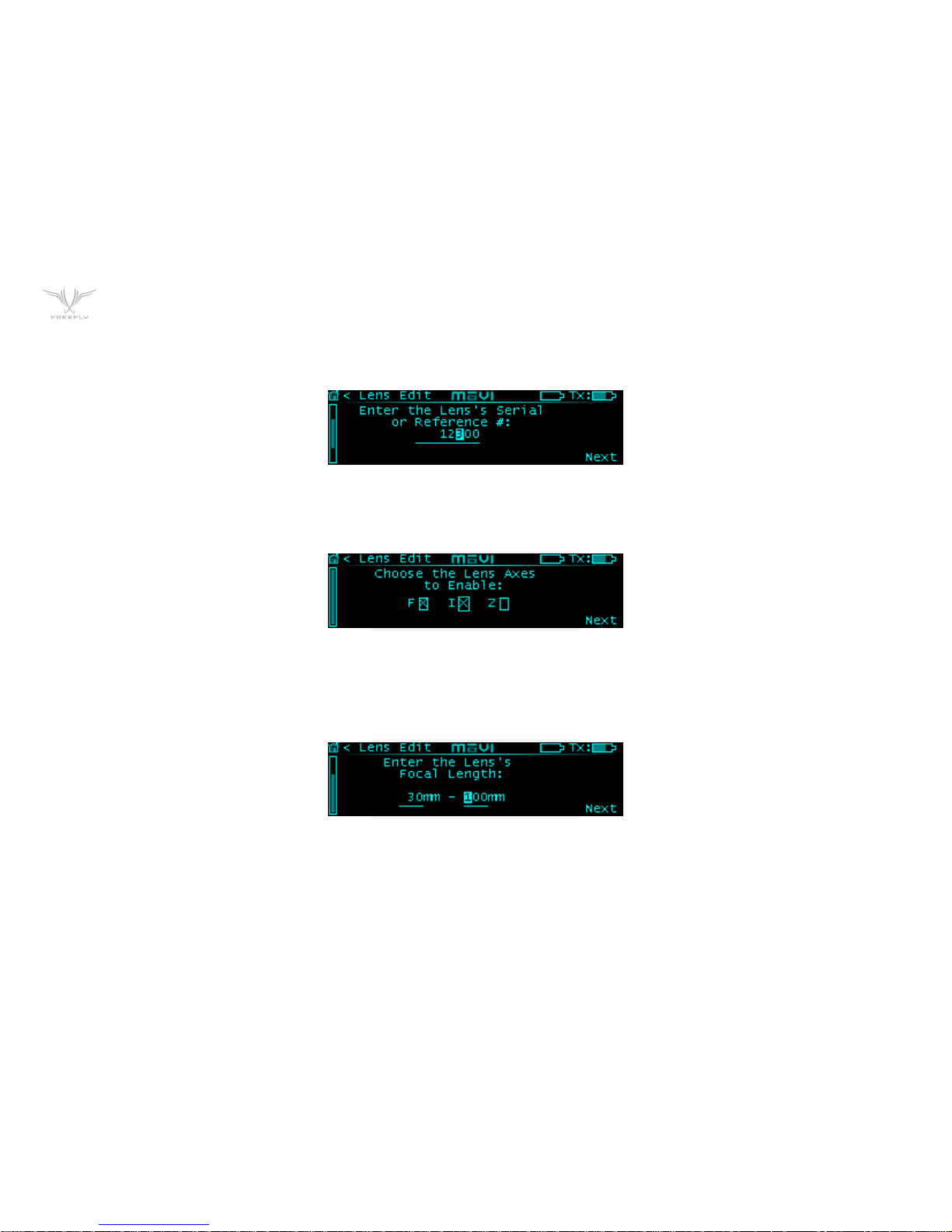
SERIAL NUMBER ENTRY
This is the first screen used to enter Lens file data. Enter the serial number for the lens. Can be used to store any unique numeric identifier that allows the user to
identify the lens.
AXES SELECT
Select the axes of the lens to enable mapping. If a specific axis is checked, that means that it is active.
FOCAL LENGTH ENTRY
Focal length entry for the lens in mm. A range is shown for zoom lenses while a single value is shown for primes. It is important to enter the actual focal length, as this
is used in the focal distance calculations.
Page 43

P43
FOCUS MAPPING POINTS
These Screens are used to map the focus axis points. The Infinity, and close focus points must be added while the others are optional. The Controller sugests
common mapping points that are typically marked on Cinema prime lenses of the selected focal length, however, these can be adjusted if necessary, and should
certainly be adjusted if they are not marked on the lens. You will get the best mapping accuracy if you use all of the marked points if possible. After entering the close
focus point, the values should increase towards the last marked point before infinity, which should be last mapped point.
The order they are added in is:
1. Infinity: This typically marked as the ∞ symbol on the lens.
2. Close Focus: This is the closest marked distance on the lens.
3. Intermediate Focus points: Recommended based on the focal length of the lens, and marks commonly found on cinema prime lenses of that length.
4. Finish Early: The "Finish" option should be used if there are no more marked positions on the lens and there are still points left.
Page 44

P44
IRIS MAPPING POINTS
These Screens are used to map the iris axis travel.
1. Iris Maximum Aperture (Low F-Stop)
2. Intermediate Aperture Points
3. Iris Minimum Aperture (High F-Stop)
Page 45

P45
ZOOM MAPPING POINTS
These Screens are used to map the Zoom axis travel.
1. Zoom Minimum Focal Length
2. Zoom Intermediate Focal Length
3. Zoom Maximum Focal Length
Page 46

P46
HOW TO
HOW TO SET UP CAMERA RUN/STOP
1 Navigation: Home -> FIZ Config -> Camera Type (Scroll SET).
2 Settings Action: Save (Scroll SET).
3 Press SET Button.
4 Connect the selected camera connection cable.
AUTOMATIC CALIBRATION OF A SINGLE AXIS
1 Navigation: Main -> FIZ Detail -> CAL: AT (Scroll SET to AT).
2 Press SET Button.
1 Motors will test motion in both directions, then sense hard stops.
2 Status is displayed in the “STAT:” field on the display.
HOW TO SET UP YOUR MOTOR TYPE
1 Navigation: Home -> FIZ Axis Cfg -> Motor Model (Scroll SET).
2 Settings Action (Scroll SET to Save).
3 Press SET Button.
AUTOMATIC CALIBRATION OF ALL AXES SIMULTANEOUSLY
1 Navigation: Main -> FIZ Main -> CAL.
2 Press SET Button.
3 Motors will test motion in both directions, then sense hard stops.
Page 47

P47
HOW TO SET UP CAMERA RUN/STOP
1 Navigation: Main -> FIZ Detail -> CAL: MN (Scroll SET to MN)
2 Press SET Button.
3 Use Zoom Rocker to move Motor to limit 1.
4 CAL: MN (Scroll SET to MN)
5 Press SET Button to save limit 1.
6 Use Zoom Rocker to move Motor to limit 2.
7 CAL: MN (Scroll SET to MN)
8 Press SET Button to save limit 2 and finish calibration.
SETTING SUB RANGE LIMITS
1 Move Motor to Limit End Point 1.
2 Navigation: Main -> FIZ Detail -> Limits or Main -> FIZ Main -> Limits
3 Press SET Button to Save Limit End Point 2.
4 Move Motor to Limit End Point 2.
5 Release SET Button to Save Limit End Point 2.
6 Press and Release SET again to clear limits.
Page 48

P48
HOW TO TUNE AN AXIS
1 Navigation: Main -> FIZ Axis Cfg -> Damping
2 Set to desired level based on damping smoothness preference.
3 Navigation: Main -> FIZ Axis Cfg -> Torque Limit
4 Set to desired level. The ideal setting is the lowest level that doesn’t cause the axis to limit current.
5 Navigation: Main -> FIZ Axis Cfg -> Speed Limit
6 Set to desired level. The ideal setting is where the axis doesn’t stop sharply when coming to a stop after moving the knob quickly.
7 Settings Action: Save (Scroll SET)
8 Press SET Button.
Page 49

P49
SPECIFICATIONS
POWER INPUTS
Motors not running: 10.0 VDC – 28.0 VDC 0.1A
Single Motor Stalled Max Peak: 10.0 VDC – 28.0 VDC 3.1A
Single Motor Stalled Max Continuous: 10.0 VDC - 28.0 VDC 2.1A
Three Motors Stalled Max Peak: 10.0 VDC - 28.0 VDC 9.1A
Three Motors Stalled Max Continuous: 10.0 VDC - 28.0 VDC 6.1A
POWER OUTPUTS
CAN Port: Voltage = VBA IN, 5A Max Time Delay Fused
CAM/RS232 Port: 5VDC, 200mA Thermal Resettable Fuse
DIGITAL OUTPUTS
CAM/RS232 Port Pin 5: 200mA Thermal Resettable Fuse
CAM/RS232 Port Pin 6: 25mA Max
RADIO TRANSMITTER
Frequency: 2.410 - 2.465 GHz
Transmitter Power: Power Level 0 (EU): +10dBm, Power Level4: +18 dBm
CAM/RS232 Port Pin 6: 25mA Max
PHYSICAL
Weight: 111 grams (Including Antenna, exluding MōVI Top Rail Mount)
Dimensions: 122mm x 55mm (Including Antenna, exluding MōVI Top Rail Mount)
Page 50
P50
CONNECTORS AND PINOUTS
POWER INPUTS
LEMO FGG.0B.302.CLAD52
("JGG" Short Body)
Pin 1 - +VDC IN
Pin 2 - GND
MOTOR
LEMO FGG.0B.307.CLAD52
("JGG" Short Body)
Pin 1 - Motor A
Pin 2 - Motor B
Pin 3 - Encoder CH A
Pin 4 - Encoder +5V
Pin 5 - Endocder GND
Pin 6 - Encoder CH B
Pin 7 - Motor ID Sense
CANBus*
LEMO FGG.0B.304.CLAD52
("JGG" Short Body)
Pin 1 - GND
Pin 2 - CAN L
Pin 3 - +VDC IN
Pin 4 - CAN H
CAM/RS232
LEMO FGG.0B.304.CLAD52
("JGG" Short Body)
Pin 1 - GND
Pin 2 - +5VDC
Pin 3 - RS232 TXD
Pin 4 - RS232 RXD
Pin 5 - LANC SIGNAL / GPIO PULL DOWN OUT
Pin 6 - +3.3VDC GPIO OUT
* For Future Expansion
Page 51

P51
WWW.FREEFLYSYSTEMS.COM
 Loading...