

Freefly M?VI Controller, MoVI User Manual
USER GUIDE
COMPATIBILITY
The MōVI Controller is compatible with the MōVI M5,
M10, and M15 running firmware version 3.08 or later.
Download the latest MōVI firmware and update
instructions at www.freeflysystems.com.
See Follow-Focus Integration section for information on
wireless lens control system compatibility.
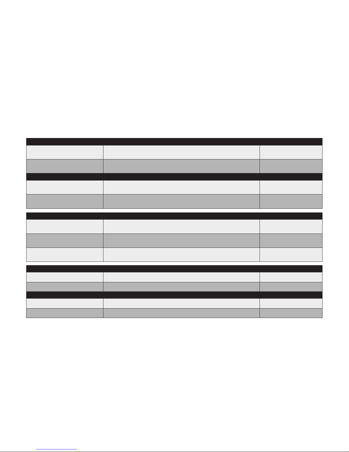
CONTROLLER SPECIFICATIONS
External DC Supply or Battery
13.0 V - 20.0 V 0.2 A
13.0 V - 20.0 V 3.2 A
4.75 V - 5.25 V 0.4 A
Controller Only (No Monitor), Power Level 4
Controller and Monitor, Max.
Controller Only (No Monitor), Power Level 4
USB
POWER INPUTS:
12V DC Output
11.4 V - 12.6 V
3.0 A
4.50 V - 5.25 V
2.0 A
Input 13.0 - 20.0V, Output Current < 3.0A
Max. Current Output
Input 13.0 - 20.0V, Output Current < 2.0A
Max. Current Output
USB 5V Output
POWER OUTPUTS:
Frequency 2.410 - 2.465 GHz
+10 dBm
+18 dBm
All Channels
Power Level 0 (EU)
Power Level 4
Transmitter Power
1200 ft / 300 mPower Level 0 (EU), Outdoor Line-of-SightRange
RADIO TRANSMITTER:
Weight 950 g
300mm X 175mm X 120mm
Including Antenna, Excluding Monitor and Battery Plate
Including Antenna and Joystick, Excluding Monitor and Battery PlateDimensions
MŌVI CONTROLLER PHYSICAL:
Weight 15 g
33mm X 38mm X 15mm
Excluding Wires and Mounting Tape
Excluding Wires, Mounting Tape, Antenna
Dimensions
RECEIVER PHYSICAL:
Any MōVI M5, M10, or M15 can be configured to work with the MōVI
Controller. The MōVI must have firmware version 3.08 or later. The latest
MōVI firmware, release notes, and update instructions are available at
www.freeflysystems.com.
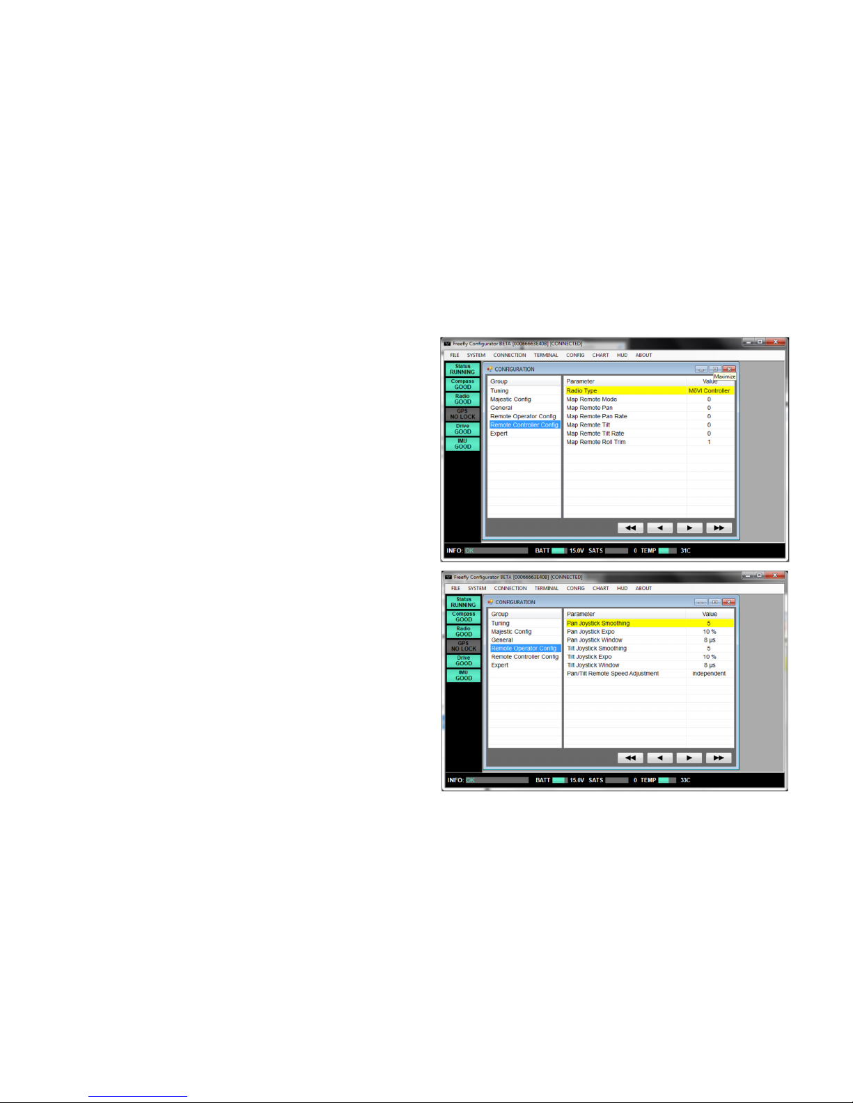
Once running firmware v3.08 or later, change the MōVI Radio Type from
the default (DSMX 2048) to MōVI Controller. This can be done from any of
the Freefly Configurator apps (PC, Mac, Android) in the Remote Controller
Config menu.
The values of the other parameters in this menu (Map Remote Mode, etc.)
do not matter for this Radio Type and can be left at their defaults.
After installing the MōVI Controller Receiver (see Receiver Installation
section below, or the Quick Start guide included in the package) and
configuring the MōVI Radio Type as above, the MōVI Controller is ready to
send commands and receive data from the MōVI. As with the Spektrum
DX7/DX8 remote controller, the feel of the joystick can be adjusted from
the Remote Operator Config menu.
MōVI CONFIGURATION:
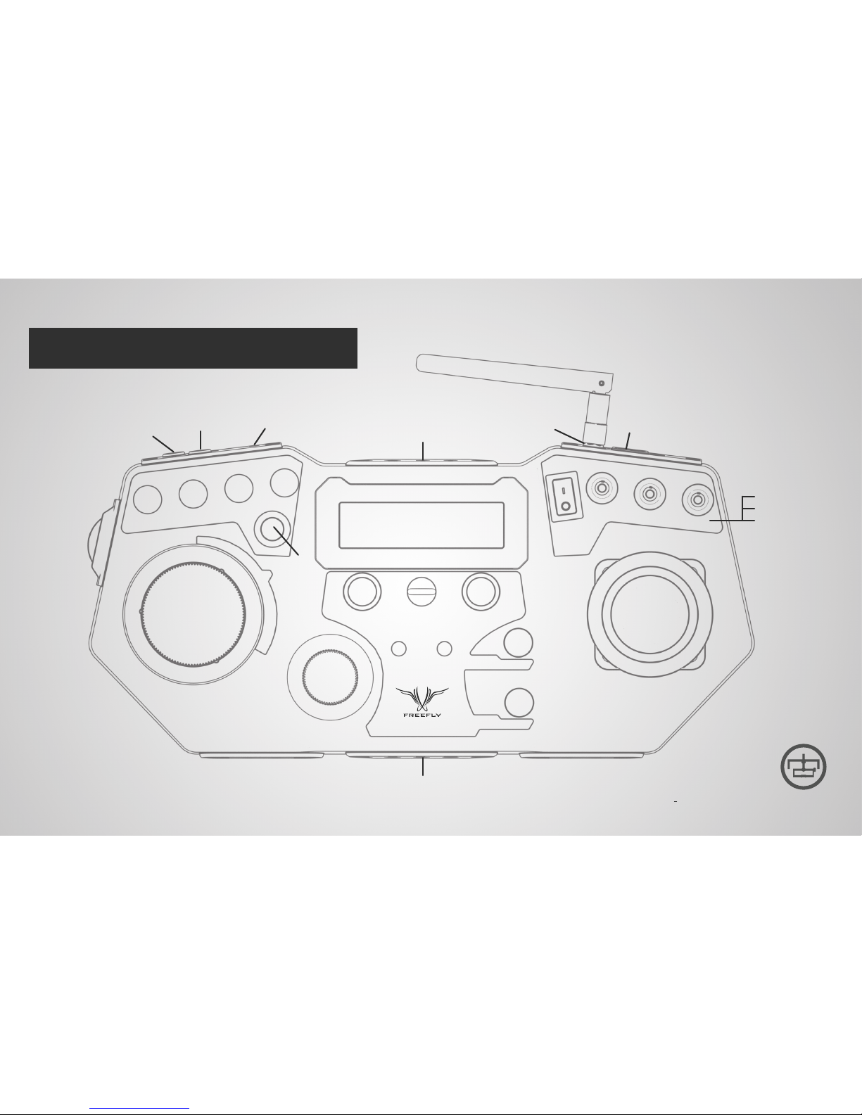
PAN
SPEED
TILT
SPEED
ROLL
SPEED
ZOOM
SPEED
RECORD
START / STOP
ZOOM
ROCKER
FOCUS KNOB
IRIS KNOB
MENU DISPLAY
NECK STRAP
EYELET
MENU SELECT
KNOB
MENU SET
KNOB
Roll Trim
BUTTONS
USER 1
KNOB
USER 2
KNOB
USER 3
SWITCH
TILT DIRECTION
MODE
PAN / TILT
JOYSTICK
POWER
SWITCH
MONITOR MOUNT / TRIPOD MOUNT
TRIPOD MOUNT
2x USB Ports
DualOperator
Majestic MODE
Kill
2.4 GHz Antenna
12V DC Output
(2-pin LEMO)
Auxiliary Data
Port (7-pin LEMO)
13-20V DC Input
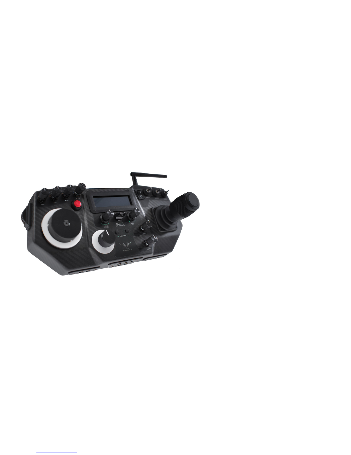
MōVI CONTROLLER LAYOUT
MoVI CONTROLLER // FULL CONTROL AT YOUR FINGERTIPS
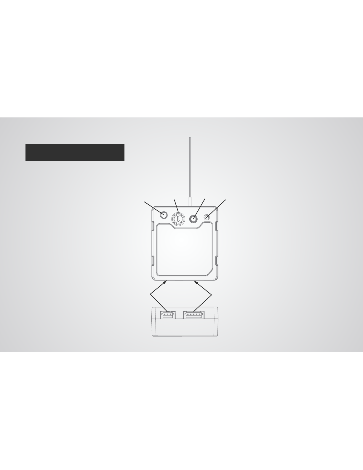
RECEIVER LAYOUT
Status LED
Channel Switch
2.4GHz Receiver Antenna
Bind Button
Firmware Update (FW) Button
5-pin Mo
oVI Data Port
3-pin Spektrum Remote Port
Shutter/Record Output Port
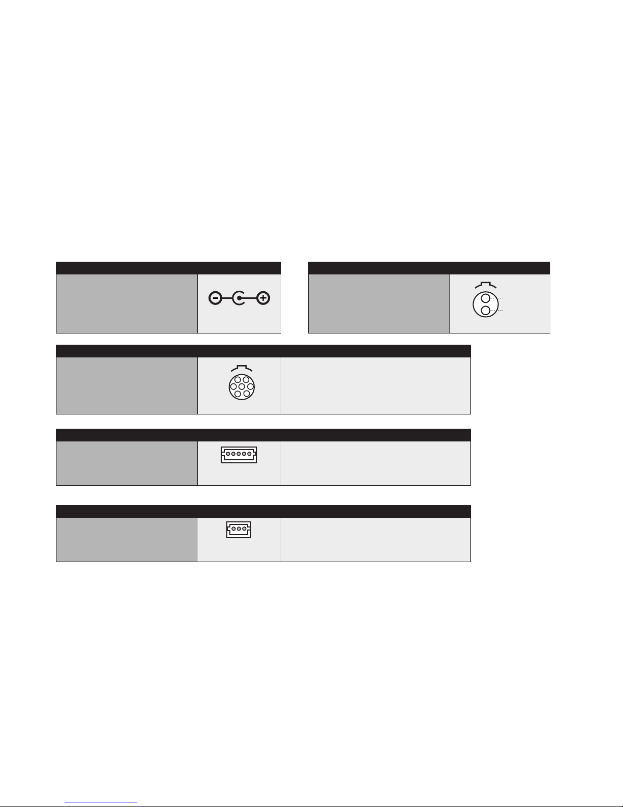
CONNECTORS AND PINOUTS
5.5mm OD
2.1mm ID Barrel Jack Connector
Center Positive
e.g. CUI Inc PP3-002A
13-20V DC INPUT
2-pin LEMO
FGG.0B.302.CLAD52
12V DC OUTPUT
TYPE
(LOOKING IN TO CONTROLLER-
SIDE CONNECTOR)
12V DC OUTPUT, 3A MAX
GND
302
1
2
7-pin LEMO
FGG.0B.307.CLAD52
AUXILIARY DATA PORT
TYPE
307
GND
5V Output, 1A max.
GPIO1 (0.0V - 3.3V)
GPIO2 (0.0V - 3.3V)
GPIO3 (0.0V - 3.3V)
Auxiliary Data Out (3.3V digitial output)
Auxiliary Data In (3.3V digital input, 5V tolerant)
1 2 3 4 -
5 6 7 -
1 6
7
2 5
4
3
5-pin JST ZH
ZHR-5
RECEIVER DATA PORT
GND
5V Input
Data In (3.3V digital input, 5V tolerant)
Data Out (3.3V digital output)
GPIO1
1 2 3 4 5 -
1 2 3
4 5
3-pin JST ZH
ZHR-3
RECEIVER SPEKTRUM / RECORD OUTPUT PORT
3.3V Input
GND
Shutter/Record or Spektrum Data Out
(3.3V digital output)
1 2 3 -
1 2 3
(LOOKING IN TO CONTROLLER-
SIDE CONNECTOR)
(LOOKING IN TO RECEIVER-
SIDE CONNECTOR)
(LOOKING IN TO RECEIVER-
SIDE CONNECTOR)

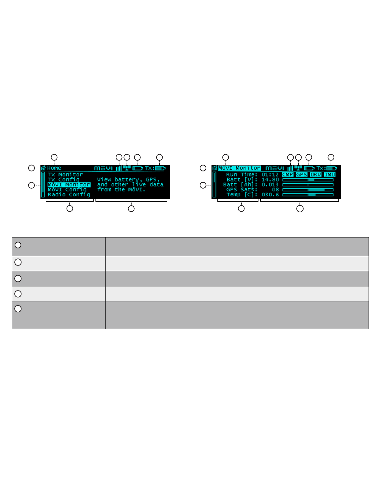
DISPLAY LAYOUT
HOME SCREEN
TYPICAL MENU SCREEN
9
1
8
7
2 3 4 5 6
9
1
8
10
2 3 4 5 6
1
2
3
4
5
HOME ICON:
Return to the Home menu at any time by scrolling (with the Menu Select knob) to and clicking on the Home
icon in the top left corner of the display.
GPS STATUS:
When the Mōvi acquires GPS lock, the GPS icon () is displayed and GPS-based acceleration compensation
(to minimize horizon drift during high-acceleration movement) is active.
MōVI BATTERY LEVEL: The state of charge of the MōVI battery. Check the MōVI Monitor menu for the exact battery voltage.
MENU TITLE:
The title of the currently active menu is displayed here.
MōVI STATUS: When connected to a MōVI, this icon will display the MōVI Status:
Booting:
The MōVI is starting up. Keep the camera stationary while this icon is displayed for the IMU to properly initialize.
Error:
The MōVI is connected, but an error has occured. Check the MōVI Monitor menu for more information on the
cause of the error, or try restarting the MōVI.
Connected:
The MōVI is connected and running, and the MōVI Controller is receiving live telemetry.
6
TRANSMITTER BATTERY LEVEL: The state of charge of the MōVI Controller battery. See Power section for details on what batteries can be
used with the MōVI Controller.
7
8
9
10
MENU DESCRIPTION:
A brief description of each menu accessible from the Home menu.
SCROLL BAR:
The scroll bar always appears on the left side of the display and shows the current scroll position, indicating if
there are more menu items above or below the ones currently displayed.
MENU ITEM DETAILS:
Within a menu, details for each menu item are shown on the right side of the display. These include status
indicators and bar graphs for menu items that are read-only, and adjustable values or options for menu items
that can be modified. Use the Menu Set Knob to change values or select options where applicable. Refer to the
individual menu descriptions in the Menu Structure section for details on each menu item.
MENU LIST:
A list of menu items. The highest-level menus appear on the Home menu. Individual menu items appear within
their respective menu. Scroll through and select a menu item using the Menu Select Knob.
HOME SCREEN
TYPICAL MENU SCREEN
9
1
8
7
2 3 4 5 6
9
1
8
10
2 3 4 5 6
 Loading...