

Page 1
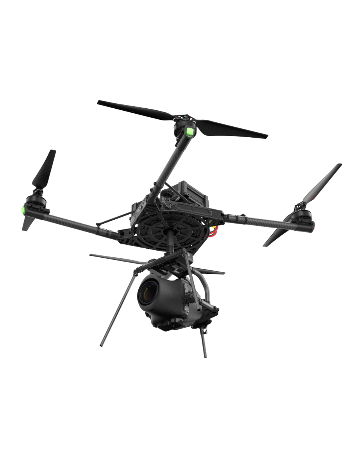
ALTA X
Features
Worlds Toughest Drone Flight Time
Introducing the world's toughest drone: ALTA X.
Page 2

ALTA X folds to 30% of its full size to fit in
ALTA X is designed to be a platform that
In order to keep ALTA X in the field as
Speed
Packability
External Power
Easy Integration
Never worry about keeping up with the
the same case as ALTA 8 while still being
Five user accessible power expansions
can be customized for any aerial need;
much as possible all ALTA X parts can be
Easy Deployment
Flight Modes
Expandability
External Computer
We’re confident in ALTA X because we
action again, ALTA X has a top speed of
able to carry 175% ALTA 8’s payload. This
allow ALTA X to power any accessories or
from cinema, to forestry, and bridge
bought as spares and replaced onsite. Of
push it to the limit, and then well past -
over 60mph (95km/h), just make sure that
case is TSA approved and has been tested
payloads you need to do the job.
inspection, ALTA X is a versatile tool ready
course we will still offer factory checkups
over and over again so that we know our
the action can keep up with ALTA X!
to ensure ALTA X arrives to location ready
for any challenge.
and repair services should they be needed!
customers will have plenty of margin in the
to go!
Like all Freefly products, ALTA X is backed
User repairable
unpredictable real world.
High quality sensors and GPS modules
by a team of experts ready to answer any
Customer Service
Payload
allow ALTA X to maintain its position and
questions and make sure you get the job
ActiveBlade
height even in the most unfavorable
done.
ALTA X can carry up to a 35lb payload
weather conditions providing assurances
while maintaining a 2:1 thrust to weight
during autonomous waypoint missions and
ratio.
piloted flights.
Four ActiveBlades reduce the motor
vibrations to 1/5th the normal level. This
No assembly required! Using a clever rotating
Designed with the future in mind, ALTA X is
Some drone applications require real time
planar linkage ALTA X folds and unfolds with
modular and easily expandable to adapt to
onboard computing; ALTA X has the necessary
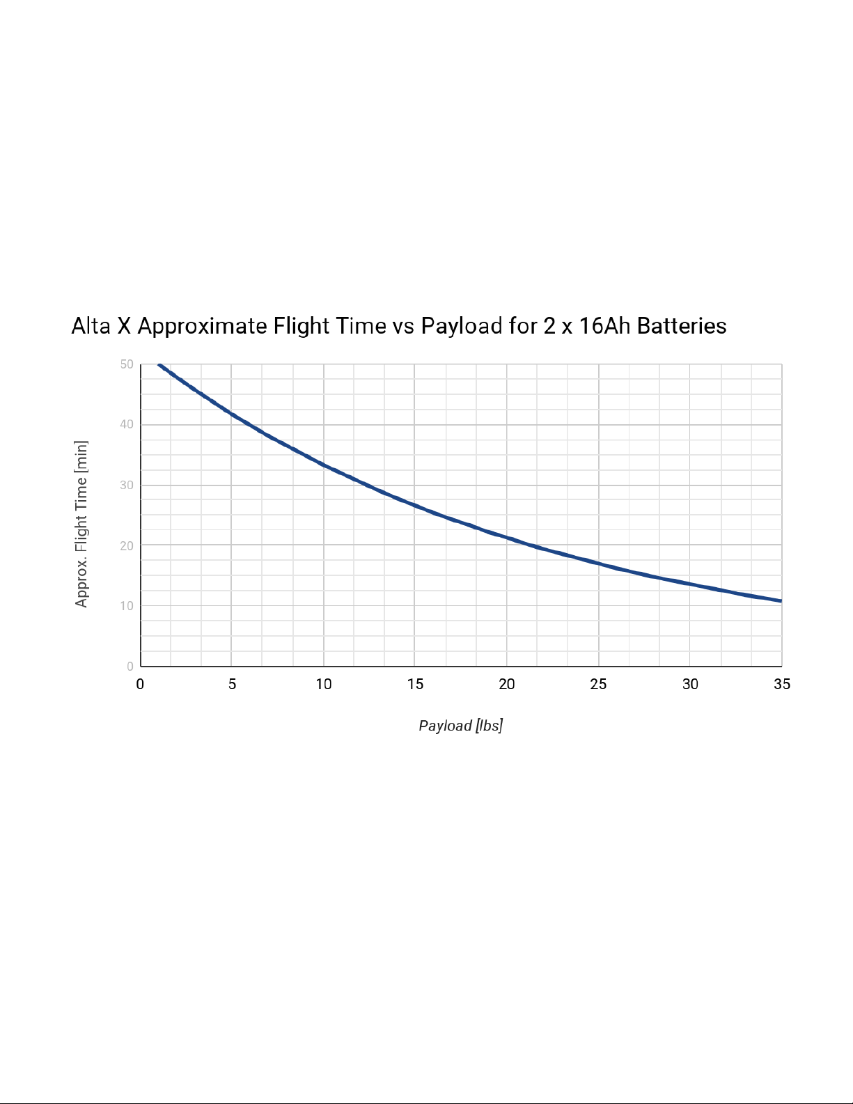
An effort to make ALTA X as light as possible
ease! This revolutionary feature allows ALTA X
ever changing technology. This expandability
mounts, power, and I/O so it can be upgraded
allows ALTA X to fly MōVI Carbon (20lb
to go from case to flight within minutes,
ensures that ALTA X will continue to be statewith an external computer.
payload) for 25 minutes, or a max payload for 8
reducing setup time and minimizing the risk of
of-the-art even after years of service.
minutes. Smaller payload flight times can
misassembly on the job.
exceed 40 minutes
innovative solution to reduce vibrations
increases the lifetime of ALTA X and helps
keep any payload stable.
Page 3
We’re confident in ALTA X because we
An effort to make ALTA X as light as possible
push it to the limit, and then well past over and over again so that we know our
customers will have plenty of margin in the
unpredictable real world.
Introducing ALTA X
allows ALTA X to fly MōVI Carbon (20lb
payload) for 25 minutes, or a max payload for 8
minutes. Smaller payload flight times can
exceed 40 minutes
ALTA X is a professional multi-rotor aircraft designed for demanding cinematic,
professional, and industrial applications. Completely redesigned from the ground up, ALTA X
is the next generation of the ALTA family. Built for the user, ALTA X emphasizes
expandability and customization to make sure it can stand up to all challenges thrown its
way, while still being the reliable workhorse drone that ALTA pilots know and love.
This Aircraft Flight Manual describes the complete operation of airframe and flight control
systems, and the normal maintenance of those items. Do not operate ALTA X without
reading and understanding this manual.
This manual is not a substitute for adequate flight training. Training requirements can vary
Page 4

when operating in different countries or under different flight conditions. Always consult
local regulations before flying ALTA X. In areas where there are no flight training
requirements, it is the sole determination of the pilot-in-command as to whether he or she
has the appropriate level of training or experience for a given flight. Always set and adhere
to personal minimums and fly within your own capabilities.
Throughout the manual warnings, cautions and notes are used to highlight various
important procedures. These are defined as follows:
{% hint style="danger" %} Warnings are used to highlight procedures which, if not strictly
observed, may result in personal injury. {% endhint %}
{% hint style="warning" %} Cautions are used to highlight procedures which, if not strictly
observed, may cause damage to equipment. {% endhint %}
{% hint style="info" %} Notes are used to highlight specific operating conditions, usability
tips and tricks or steps of a procedure. {% endhint %}
Legal
Disclaimer and Warning
Please read this disclaimer and warning carefully and review the ALTA X Aircraft Flight
Manual (AFM) prior to flight. If you have any questions, please contact
support@freeflysystems.com prior to using the ALTA X. You can review the most current
version of this manual on the ALTA X Support Page. By using ALTA X, you acknowledge that
you have read, understand and agree to this disclaimer. You agree that you are solely
responsible for your conduct while using ALTA X, and for any direct or indirect consequences
that may result from its use. You agree to only use ALTA X for proper purposes that are in
accordance with local and airspace rules and regulations.
ALTA X is not a toy and should be operated with extreme care, as improper operation
can cause damage to property, serious personal injury or death.
As with any multi-rotor aircraft, ALTA X is a complex and technical machine. Novice
Page 5

pilots should invest sufficient time on a flight simulator and seek training from an
experienced pilot prior to operation. The ALTA X Aircraft Flight Manual and a flight
simulator are no substitute for training with an experienced pilot, particularly when it
comes to learning how to safely operate ALTA X. Novice pilots should never fly without
the supervision of an experienced pilot.
Always check ALTA X and its components prior to operation.
Always maintain a safe distance from ALTA X when in use.
Never attempt to touch ALTA X when the propellers are moving.
Never fly ALTA X over or around people, power lines or other aircraft.
Never fly with any propellers that have visible imperfections or damage.
Always keep children and animals a safe distance away from ALTA X when in use and
when changing configurations.
Only use propellers supplied by Freefly Systems that are designed for use on ALTA X.
Always remove the propellers or power ALTA X using a low power source when making
a change to the configuration of ALTA X to prevent propeller strikes in the event of
unintentional motor starts.
Always remove the configuration jumper when making changes to the configuration of
ALTA X.
Always test ALTA X with the propellers removed to make sure that the motors are
spinning in the correct direction and that the motor assignment is correct with respect
to the Autopilot flight controller. If you have either of these wrong, the ALTA X will be
uncontrollable and dangerous.
It is your responsibility to perform a full system check of ALTA X prior to every flight.
It is your responsibility to learn how to safely operate ALTA X and to adhere to all
applicable rules and regulations.
Fly at your own risk.
ALTA X is a tuned system with custom components selected for each application.
Modification, removal, or substitution of ALTA X components will void the warranty
and can lead to unsafe operating conditions.
Limitations of Liability
IN NO EVENT SHALL FREEFLY BE LIABLE TO BUYER FOR ANY INDIRECT,
Page 6

CONSEQUENTIAL, PUNITIVE, INCIDENTAL, OR SPECIAL DAMAGES, OR ANY DAMAGES
WHATSOEVER RESULTING FROM THE USE OF ALTA OR FROM LOSS OF USE, DATA OR
PROFITS (HOWEVER CAUSED AND UNDER ANY THEORY OF LIABILITY), EVEN IF
FREEFLY HAS BEEN ADVISED OF THE POSSIBILITY OF SUCH DAMAGES. IN NO EVENT
SHALL FREEFLY’S LIABILITY FOR A PRODUCT (WHETHER ASSERTED AS A TORT CLAIM,
A CONTRACT CLAIM OR OTHERWISE) EXCEED THE AMOUNTS PAID TO FREEFLY FOR
SUCH PRODUCT. NOTWITHSTANDING ANYTHING HEREIN, IN NO EVENT SHALL
FREEFLY’S LIABILITY FOR ALL CLAIMS ARISING OUT OF OR RELATING TO THIS
AGREEMENT EXCEED THE AMOUNTS PAID BY BUYER TO FREEFLY FOR PRODUCT IN
THE LAST TWELVE (12) MONTHS. IN NO EVENT WILL FREEFLY BE LIABLE FOR COSTS OF
PROCUREMENT OR SUBSTITUTE GOODS BY BUYER. THE LIMITATIONS SET FORTH
HEREIN SHALL APPLY TO ALL LIABILITIES THAT MAY ARISE OUT OF THIRD-PARTY
CLAIMS AGAINST BUYER. THESE LIMITATIONS SHALL APPLY NOTWITHSTANDING ANY
FAILURE OF ESSENTIAL PURPOSE OF ANY LIMITED REMEDY. Freefly shall not be liable for
damages or injuries incurred directly or indirectly from the use of ALTA X including, but not
limited to, the following situations:
Failure of the operator to follow proper instructions and safety warnings found at
www.freeflysystems.com.
Failure of the operator to understand and operate the aircraft within the operating
limitations described in this manual.
Failure of the operator to follow onboard safety warnings while using ALTA X.
Failure of the operator to follow and comply with local rules and regulations.
Failure of the operator to follow and comply with the local communications law.
Failure of the operator to inspect ALTA X and its components prior to operation.
Failure of the operator to properly maintain and/or service ALTA X through an
authorized Freefly Service Center with genuine ALTA X parts.
Use of third-party products on ALTA X.
Use of ALTA X in a physically or mentally impaired capacity.
Use of ALTA X without sufficient training.
Use of ALTA X in unsafe conditions, including but not limited to, bad or severe weather,
such as rain, wind, snow, lightning, dust storms, etc., or in areas of magnetic or radio
interference, such as power stations, broadcasting and cell phone towers, government
Page 7
prohibited airspace, etc.
Improper operation, misjudgment or risky behavior while using ALTA X.
Infringement of third party data, audio, or video rights recorded when using ALTA X
Appendix
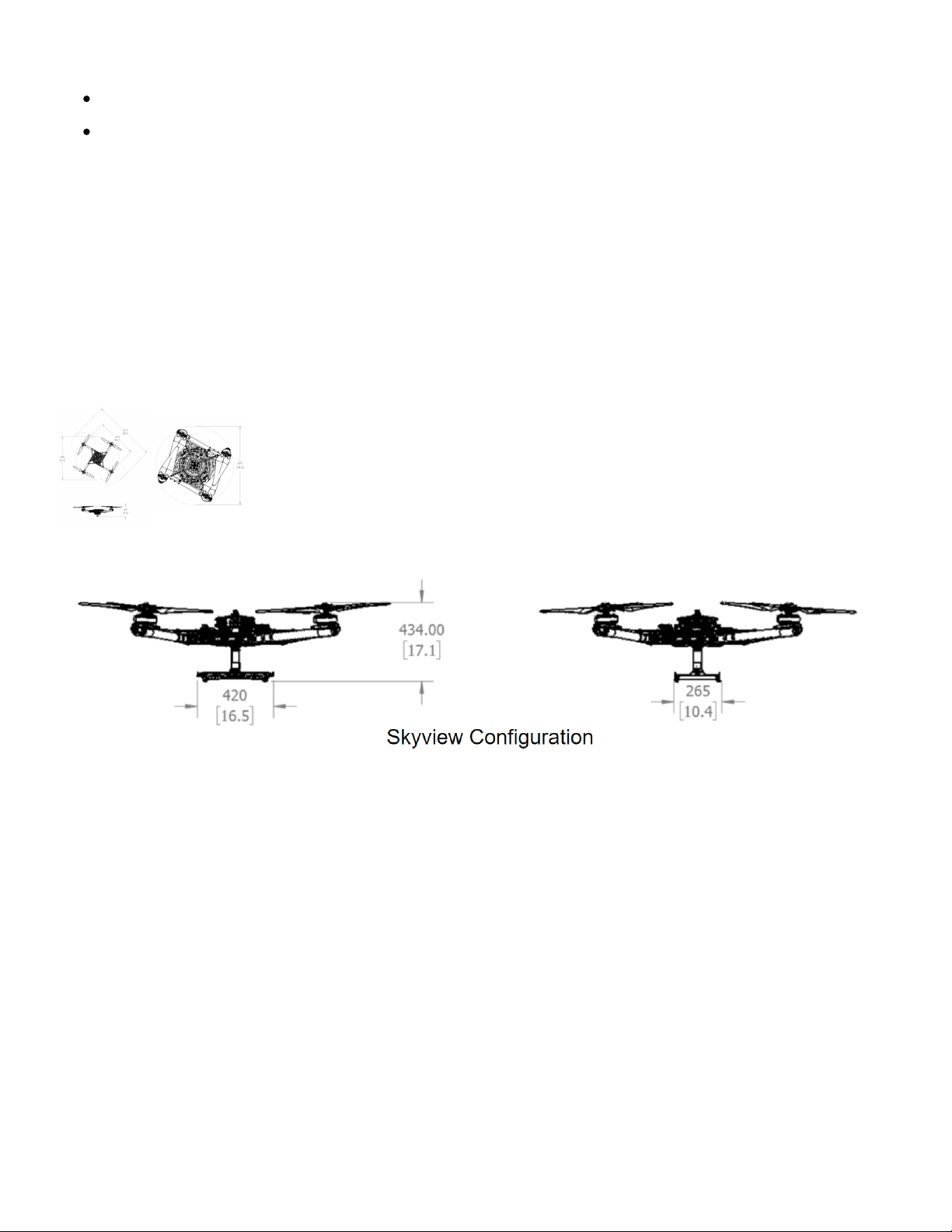
Specifications
Dimensions
Dimension Length [mm]
Unfolded Diameter (not including props)
1415
Unfolded Diameter (Including Props)
2273
Folded Diameter
877
Height
387
Page 8

Dimension Length [mm]
Height (Skyview) 434
Powerplant
Number of Motors 4
Motor Max Continuous Power Output 100 A
Motor Max Instantaneous Peak Power Output 130 A (>3s)
Equivalent Kv 115 rpm/V
Propellers
Material Carbon Fiber Reinforced Nylon
Propeller Orientation (2x) CW and (2x) CCW Props
Propeller Type Folding - 840 x 230 mm (33 x 9in)
Battery
Cells 12S
Nominal Battery Voltage 44.4V
Charged Battery Voltage 50.4V
Battery Connectors XT-90
320 Amps per battery
Required Minimum Battery Discharge
Rating (Per Pack)
(assumes two batteries) 20C for a 16Ahr pack.
Weight
Maximum Gross for Takeoff 34.9kg
Maximum Payload 15.9kg
Typical Standard Empty Weight 10.4 kg
Page 9

Flight Controller
Autopilot Name Custom Auterion PX4 flight control stack
Flight Modes Manual, Altitude, Position, Mission, Loiter, Orbit, Return
Supported Inputs MAVlink SDK
Futaba, Spektrum, PX4 compatible SBUS and PPM
Supported Radios
receivers
Supported Radio Controller
Voltage feed provided for Futaba RX telemetry
Telemetry Systems
Minimum Radio Controller
5 (roll, pitch, yaw, throttle, mode)
Channels Required
Supported GNSS GPS/Glonass/Beidou/Galileo
Lighting and Indication
Orientation Lights Boom tip mounted LEDs
Orientation Light Color
Options
FPV Ability
User controlled in software - red, orange, yellow, green, cyan,
blue, purple, white, and off.
Yes, see the FPV integration section for instructions on how
to mount the FPV.
Isolation Systems
Vibration Isolation System Built-in (see chart below for weight suggestions)
Payload [lb] Payload [Kg] Isolator Durometer Cartridge Qty
0 - 3 * 0 - 1.4 30A 3
4 - 10 * 1.8 - 4.5 30A 6
11 - 19 ** 5.0 - 8.6 30A 9
20 - 23 ** 9.1 - 10.4 30A/40A 9
24 - 29 ** 10.9 - 13.2 40A 9
30 - 32 ** 13.6 - 14.5 40A/50A 9
Page 10
Payload [lb] Payload [Kg] Isolator Durometer Cartridge Qty
33 - 35 ** 15.0 - 15.9 50A 9
>35 *** >15.9 60A 9
Performance Charts
Flight Time v. Payload
Maximum Gross Weight
To determine maximum gross weight, determine flight location pressure altitude and
temperature, and refer to the weight in the chart below. Gross Weight includes payload,
battery and structure weight.
Page 11
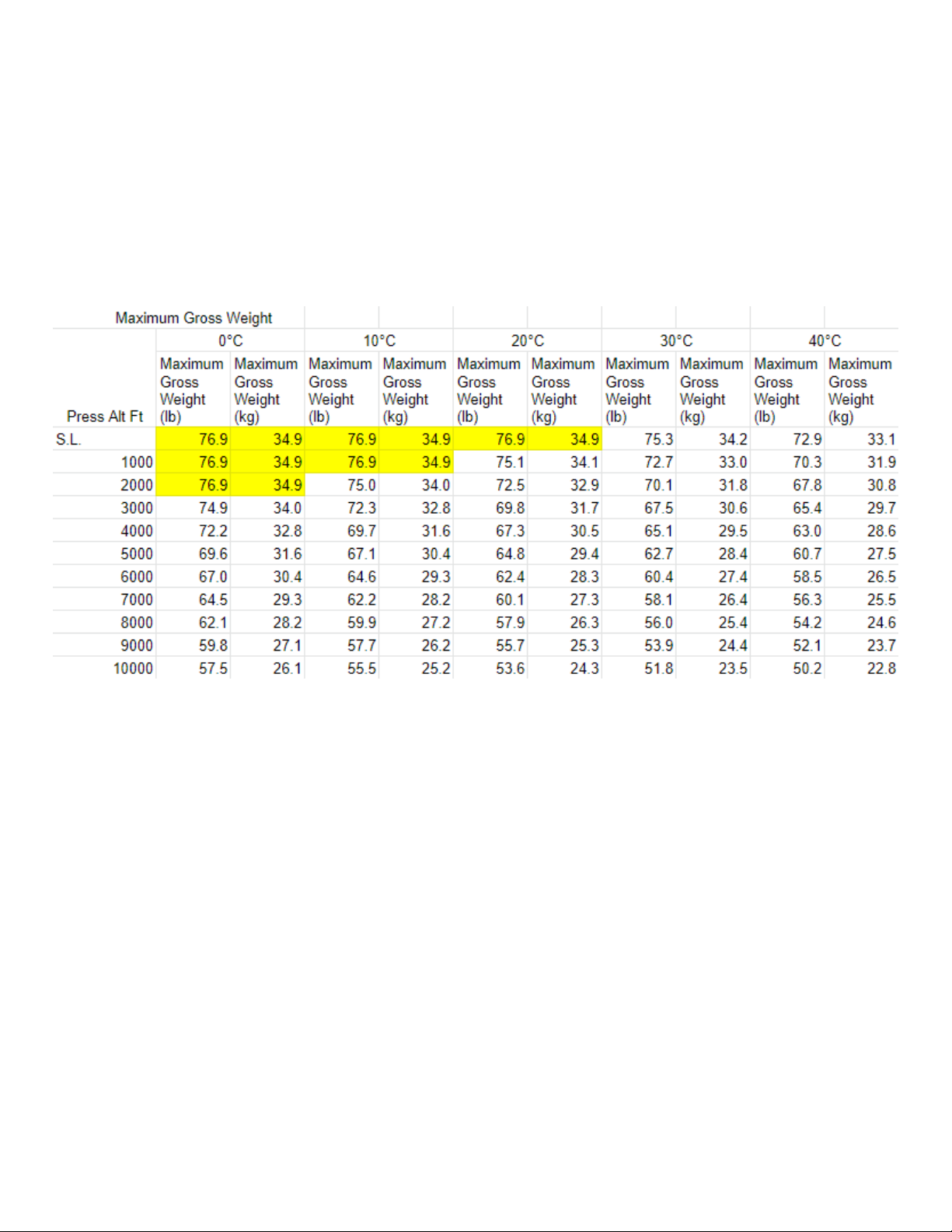
The maximum gross weight might exceed the weight allowed by regulatory agencies. When
determining gross weight, please consider any such local restrictions on aircraft weight when
planning aircraft weight.
{% hint style="info" %} The maximum gross weight at a defined density altitude was
established by calculating weight so that sufficient thrust margin for maneuvering is
maintained. {% endhint %}
{% hint style="info" %} Cells highlighted in yellow indicate where the weight is limited by the
maximum design weight {% endhint %}
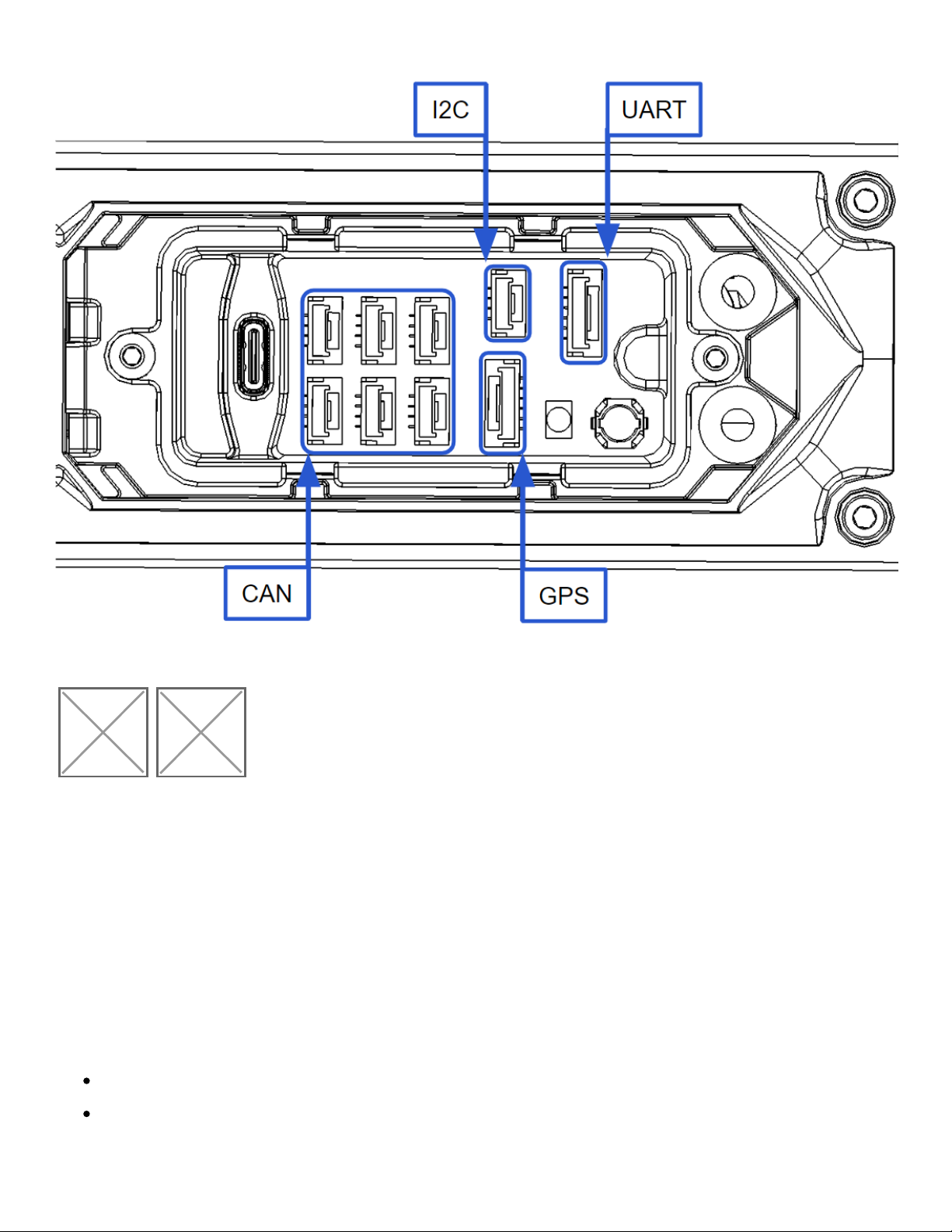
Expansion Ports
External Com Expansion
The external communications expansion port is located between booms 1 and 2 on the ALTA.
Page 12
GH-6 Pin GH-4 Pin
Image not found or type unknownImage not found or type unknown
5V External Power
The external expansion connector port 5V power is provided by a dedicated 5V 3A current
limited power supply separate of the redundant 5V power supplies for the flight controller.
Each output on the external expansion connectors is protected by a 1.1A hold 2.2A trip PTC
(Part number 0ZCG0110FF2C). The sum of the power supplying the following components
must be less than 3A:
Motor boom LEDs (approx 1A during flight with 2x red and 2x green LEDs)
Long range radio if not powered via other means (FRX Pro is powered by 12V)
Page 13

All internal CANbus peripherals on CAN expansion connectors
All external UART, I2C, and CANbus connectors
UART Port - GH-6 Pin
MAVLink serial communications at 57600b 8-N-1
Pin Signal Voltage (V)
1 VCC +5V
2 TX (Out) +3V
3 RX (In) +3V
4 CTS (In) +3V
5 RTS (Out) +3V
6 GND GND
GPS2 Port - GH-6 Pin
Nuttx console output at 57600b 8-N-1.
Pin Signal Voltage (V)
1 VCC +5V
2 TX (Out) +3V
3 RX (In) +3V
4 I2C1 SCL +3V
5 I2C1 SDA +3V
6 GND GND
CAN Ports - GH-4 Pin
Peripheral CANbus for future expansion.
Pin Signal Voltage (V)
1 VCC +5V
Page 14

Pin Signal Voltage (V)
2 CAN_H +5V
3 CAN_L +5V
4 GND GND
{% hint style="warning" %} WARNING: Internal Long Range RF CAN is 12V VCC, do not use!
{% endhint %}
I2C Ports - GH-4 Pin
I2C bus for future expansion
Pin Signal Voltage (V)
1 VCC +5V
2 I2C1 SCL +3V
3 I2C1 SDA +3V
4 GND GND
Power Expansion
The power expansion port is located between booms 1 and 2 on the ALTA; it contains three
externally-facing and two internally-facing direct battery connected power expansion
connectors with female socket pin XT-30 type connectors. Each external output is protected
by a 10A automotive mini blade type fuse. The replacement fuse part number is
0297010.WXNV.
The system and fuses are sized to supply 10A or less continuously on each external port
simultaneously; the internal connectors share the same fuse with the external connector J1.
Please note that the output voltage will vary with system battery voltage as the battery
discharges.
{% hint style="warning" %} Use of any other size fuse could cause the aircraft to crash if
shorted. {% endhint %}
Page 15

Maintenance
Interval Inspections
Every 15 Flights
ALTA X is designed to be as low-maintenance as possible. It is recommended to check ALTA
X’s fasteners regularly. This check should occur roughly after every 15 flights. To check ALTA
X’s fasteners, apply a tightening torque to each fastener on the chassis using the supplied
hex drivers. The fasteners should not slip.
Inspect Fastener Tightness
Check the tightness of the following fasteners:
Motor mount bolts
Boom clamping bolts
Prop hub bolts
Prop bolts
Top and bottom chassis bolts
Closeout panel bolts
FPV camera mounting plate bolts
Boom stay attachment bolts
GPS/Compass mounting bolts
{% hint style="info" %} If a fastener does slip, tighten it using the methods described in the
Fastener Installation section. Do not apply additional thread locking compound unless the
fastener has repeatedly come loose. {% endhint %}
Every 15 Flight Hours
Inspect Fastener Tightness
Page 16

Check the tightness of the fasteners as described above.
Inspection Wear Components
Inspect the following items. Replace if worn.
Propeller blades - Chips, cracks, or deep scratches
ActiveBlade bumpers
Broken or crushed
Inspect Boom Ring Latch Tightness
Check boom latching tightness by closing the latch. There should be a firm closing force and
click. Adjust the tension by using a 2.0mm hex wrench on the set screw located in the rear of
the latch link.
Replacement of Parts
Spare or replacement parts are available for sale separately at freeflysystems.com. Please
refer to the store for a current listing of all available spare parts.
{% hint style="warning" %} Use Of Threadlocker
Bolts and screws used in the daily use of this aircraft do not require threadlocking
compound. This includes the screws holding on the battery trays, vibration isolation system
and the Skyview landing gear parts.
However, for the structural fasteners described in parts of this section blue Loctite 243
compound or equivalent is required. Apply sparingly to the threads before insertion. {%
endhint %}
{% hint style="warning" %} Fastener Installation
The Freefly hex drivers included with ALTA X are designed to limit the torque that can be
applied to each bolt or screw and help prevent stripping the fastener head.
Thread all fasteners into their respective holes until snug (when the fastener head bottoms
Page 17

out and lightly clamps the two mating parts together).
To prevent excessive tightening and damaging the fastener or parts, twist the driver from
the smaller diameter knurled section of the tool between your thumb and index finger for
small fasteners (under size M3) or with your thumb and two forefingers for larger fasteners
(size M3 and larger). {% endhint %}
{% hint style="danger" %} Before performing any part replacement, ensure that ATLA X has
been unplugged from any power source. Leaving ALTA X powered while performing any work
on it can result in a potentially dangerous situation. {% endhint %}
Replacing ActiveBlade Bumpers
Push down on one side of the ActiveBlade assembly to open the gap and
1.
provide better access. Pull the bumper out from that side.
2. Repeat this for the second bumper.
To replace, insert the tail of the new bumper into the hole and pull into
3.
place, until the shoulder is fully seated. A circular motion may help with
seating.
To replace the second bumper, push down on the ActiveBlade assembly
4.
and again pull the tail of the bumper to seat.
Rock the the ActiveBlade assembly back and forth to make sure the
5.
bumpers are aligned.
****
Replacing Propeller Sets
First, remove the ActiveBlade bumpers as detailed in the previous
1.
section.
2. Remove (2x) M5x30 bolts and (4x) M3x10 bolts and remove the top plate.
Page 18

3. Replace props and nylon washers if required.
Refit top plate and attach with (2x) M5x30 bolts and (4x) M3x10 bolts.
4.
Loctite 243 or equivalent must be used to secure these fasteners.
5. Reinsert the ActiveBlade bumpers as detailed in the previous section.
{% hint style="warning" %} Props are supplied as a weight matched and balanced pair. Only
fit props in the factory supplied pair. {% endhint %}
****
Replacing ActiveBlades
Remove (x4) M3x10 bolts by accessing through the top of the assembly
1.
as shown.
Fit new assembly and secure with (x4) M3x10 bolts. Loctite 243 or
2.
equivalent must be used to secure these fasteners.
Opening Chassis
Set aircraft on a stable level work surface.During disassembly, take care to note the
1.
location of fasteners and orientation of parts, as this will greatly help with reassembly.
Remove the following fasteners:
1.
(x4) M4x16 Combo - which secure the boom stays to the boom
2.
(x4) M3x10 FHCS - which secure the closeout panels
3.
2.
(x4) M3x10 Combo - which secure the closeout panels
4.
(x2) M3x10 Combo - which secure the battery connector mount
5.
(x2) M3x10 Combo - which secure the center ring
6.
(x4) M4x14 Combo - which secure the center ring
7.
Remaining M4 bolts that secure the top chassis to each hinge
The top chassis can now be removed from the machine, and the inner cover lifted off
3.
to access the enclosure area.
Page 19

To reassemble, refit the enclosure making sure it is well seated and there are no
4.
trapped wires.
Attach the power connector with (x2) M3x10 bolts before reseating the top chassis,
5.
making sure the orientation is correct.
Reassemble the remaining chassis fasteners. Take care to align the fasteners correctly.
6.
It is recommended to get all fasteners started before torquing. Loctite 243 or
equivalent should be used in all these locations.
`
Replacing Booms
{% hint style="info" %} If replacing more than one boom, replace one at a time to reduce the
chances of mixing up connections. {% endhint %}
1. Remove the top chassis as detailed in the previous section.
Page 20

Trace the wires from the boom to be replaced. There will be three cables from each
2.
boom, a power cable, an LED cable and a motor control cable. Carefully unplug each,
taking care to note the locations for when the replacement boom is fitted.
3. Remove any strain relieving zip ties. Take care to note the correct wire routing.
Loosen the three M4 bolts that clamp the boom, and carefully slide the boom out of
4.
the hinge.
Remove the corrugated tube from the old boom, noting its location on the harness. If
5.
being reused, remove the ActiveBlade assembly from the old boom.
6. Prepare the new boom assembly by attaching the corrugated tube.
Feed the wiring harness through the hinge, slide the boom into place and temporarily
7.
secure by lightly tightening the hinge bolts.
Connect new boom’s three cables, route the wires and secure with strain relief zip ties
8.
where needed. Make sure the corrugated tube is positioned correctly and strain
relieved to the chassis securely.
9. Replace the enclosure cover and reinstall the top chassis per the previous section.
The booms on ALTA X are clocked to improve yaw authority. Replacement booms are
supplied with alignment cards to allow accurate clocking of the motors. Their use is
10.
covered in this video. Before aligning the motors, completely remove the M4 boom
clamp fasteners, and apply Loctitie 243 or equivalent. Once aligned, torque fasteners.
11. Reattach the ActiveBlade assembly as described in previous section.
Updating Firmware
Autopilot and system component firmware is updated via the USB expansion port on ALTA
X located in the chassis closeout between booms 1 and 2. To update firmware download the
latest FW files from the ALTA X Firmware page and follow the instructions below.
Download the latest ALTA X FW from the ALTA X Firmware page on the
1.
support website.
Plug in a USB cable to your computer. Leave the other end unplugged from
2.
ALTA X for now.
Page 21

Remove the chassis closeout between Booms 1 and 2 to reveal the
3.
expansion board.
Hold down the USB MSC Button on the expansion board while plugging in
4.
the USB C to the expansion board on ALTA Pro. Your ALTA will show up in
your file browser as a USB disk named FF-ALTA.
5. You should see a folder named FF-ALTA.
Replace the ‘freefly’ folder in the root of the drive with the new one
6.
downloaded from the Freeflysystems.com website.
Unplug ALTA X from the USB and then apply USB power (or battery power
7.
with the props removed) while holding down the Boot button on the
expansion board.
ALTA X should display blue solid or flashing lights on its motors to show it
8.
is updating its FW. Once complete the system will boot normally and
display red and green directional lights on the motors.
{% hint style="info" %} For troubleshooting, you can view details of the bootloading process
by connecting to the GPS2 UART on the expansion connector with a USB to UART adapter
and a cable using the dronecode/PX4 UART standard pinout. The UART settings are 57600
baud, 8-N-1. {% endhint %}
{% hint style="warning" %} Test radio channels, arming, and disarming behavior after
firmware updates to ensure radio mapping has been preserved. Incorrect radio mapping can
lead to loss of control. {% endhint %}
{% hint style="danger" %} Do not use a battery to power ALTA X during FW updates! Using
USB power prevents unwanted motor spin-ups. {% endhint %}
Integrations
RX Transmitter
ALTA X allows for the installation of a radio control system. S.Bus, S.Bus2, DSM2, and DSMX
receiver types are supported. Some ALTA X emergency control modes (Return-to-Land and
Page 22

Autoland) may vary depending on the type of radio. Refer to the Flight Controller Modes
section of this manual for additional details.
Installation of Futaba Radio
1. Locate the bay used for receiver installation (between booms 2 & 3 )
2. Remove quick release door with radio wires:
3. Plug signal wire into receiver.
If using telemetry, plug the telemetry wire located in the bay between
4.
booms 2 & 3 into the opposite side of the receiver.
5. Feed receiver antenna through bottom of chassis via the plastic ferrule.
Secure receiver using the provided double-sided tape to inside of
receiver housing.
6.
Replace the quick release door.
7. Route antenna wires into the two antenna tubes below ALTA X chassis.
8. Repeat installation process for dual receivers (if applicable).
Installation of Spectrum Radio
1. Locate the bay used for receiver installation (between booms 2 & 3 )
2. Remove quick release door with radio wires:
Page 23

3. Feed signal cable through panel grommet.
4. Plug in receiver/satellite into signal cable.
5. Attach receiver/satellite to exterior using double-sided tape.
Radio Controller Calibration and Mapping
ALTA X can be used with a variety of radio controllers. Different radio controllers can map
functions to different channels, so properly mapping controller channels to ALTA X functions
is an important step before flying. Radio calibration and channel mapping are performed
using the ALTA QGroundControl program or app.
If you are uncertain about your radio channel mapping, obtain assistance from an
experienced pilot or from Freefly Customer Support.
Calibrating Radios Using ALTA QGroundControl App
Calibrating any compatible radio is done using the ALTA QGroundControl app. This only
needs to be done when using a new radio with the ALTA X; ALTA X that were bought with a
radio have already gone through the Calibration and Mapping procedures.
1.
Power the ALTA X by plugging in a USB-C cable to the expansion port.
2.
The expansion port is located under the closeout between booms 1 and 2 .
3.
Once connected, the ALTA X electronics will be powered and you may turn on the radio.
4.
Open the ALTA QGroundControl program, navigate to the Radio tab in the Vehicle
Setup menu, and then initiate the radio calibration.
5.
Set the transmitter mode radio button that matches your radio configuration (this
ensures that QGroundControl displays the correct stick positions for you to follow
during calibration).
6.
Move the sticks to the positions indicated in the text (and on the radio image). Press
Next when the sticks are in position. Repeat for all positions.
7.
When prompted, move all other switches and dials through their full range (you will be
able to observe them moving on the Channel Monitor).
8.
Press Next to save the settings
Page 24

{% hint style="warning" %} Make sure to reset all trims and subtrims to zero before
continuing with calibrating and mapping your radio. {% endhint %}
Mapping Channels Using ALTA QGroundControl App
Radio channel mapping is accomplished with the ALTA Qgroundcontrol App. Prior to
mapping channels, ensure your radio controller and receivers are properly installed and
calibrated. Refer to the Radio Installation section of this manual and your radio controller’s
documentation.
1.
Power the ALTA X by plugging in a USB-C cable to the expansion port.
1.
The expansion port is located under the closeout between booms 1 and 2
2.
Once connected, the ALTA X electronics will be powered and you may turn on the
transmitter.
3.
Open the ALTA QGroundControl program, navigate to the Flight Mode tab in the
Vehicle Setup menu for access to the channel mapping.
4.
Channel mapping can be customized by the user on this menu to fit their preferences.
Below is a quick description of the items mapped to the transmitter and suggested
channels for each mapped item.
{% hint style="warning" %} Customers are advised to use tablets, laptops, or desktops to
perform the Radio Calibration and Channel Mapping; some mobile devices may crop these
menus. {% endhint %}
Function Descriptions
The following functions can be mapped to radio controller channels. These are found in the
Radio section of the Configurations menu in ALTA QGroundControl. Each function is also
represented by a chart that responds to control input allowing for quick verification of
mapping settings.
Controller
Use this to select the appropriate receiver. The following guide is compiled for convenience.
For complete specifications and which mode will work with your receiver, refer to your radio
Page 25

controller or receiver manuals.
DSM2/DSMX are typically used by Spektrum controllers
SBUS is typically used by Futaba controllers
Pitch/Roll/Yaw/Throttle
The Pitch, Roll, Yaw and Throttle controls are the basic flight controls and are mapped to the
two radio controller sticks.
Mode
The required Mode Switch selects between the three different flight modes: Manual,
Altitude, and Position. A three-position switch is recommended to select the three different
modes. However, a two-position switch may be used, but will only allow for selecting
between Manual Mode and (depending on radio controller mixes) either Altitude Mode or
Positon Mode . Other modes are available, but should be only used by experienced operators.
Return to Home Switch
The optional Return to Home Switch selects between the different Return-to-Land (RTH)
functions. At minimum a two-position switch is required for the Home Switch functions to
select between RTL Off, and initiate RTL functions.
Typical Channel Mappings
The following radio channel mapping configurations are recommendations only and can be
set in ALTA QGroundControl. Depending on exact radio models, these may help as an initial
configuration. However, it is up to the pilot setting up ALTA X for flight to determine if these
settings are appropriate.
Futaba 14SG/8FG
Function Channel Number Direction
Pitch 2 Normal
Roll 1 Normal
Yaw 4 Normal
Page 26

Function Channel Number Direction
Throttle 3 Reverse
Mode Switch 5 Normal
Home Switch 6 Normal
Spektrum DX18
Function Channel Number Direction
Pitch 3 Reverse
Roll 2 Reverse
Yaw 4 Reverse
Throttle 1 Normal
Mode Switch 6 Reverse
Home Switch 7 Normal
Page 27

FPV Camera and Transmitter
FPV System installation
Connect the FPV camera cable to the FPV extension located inside the
1.
chassis at the base of boom.
Screw the FPV mount to the top of the chassis with the (x4) M3x14
2.
screws and washers.
Screw the FPV camera bracket to the FPV mount with (x2) M2.5x5
3.
screws and washers.
Page 28

Screw the FPV camera to the bracket using the included (x4) M2x4
4.
screws and washers.
5. Plug the FPV cable into the back of the camera.
VTX System Installation
Connect the VTX cable to the VTX extension located inside the chassis at
1.
the base of boom #3
Screw the VTX and its mount to the interior of the closeout panel adjacent
2.
to the base of boom #3 using 2x M3x10 screws. Then plug in the VTX cable.
This can be done without removing the closeout panel.
Route the SMA mount and cable through the access port at the base of
3.
boom #3. Ensure you do not unplug the u.FL connector during this step.
Screw the SMA mount to the accessory mounting pattern using 2x M3x5
4.
screws
5. Attach the included TBS Triumph Antenna to the SMA jack and tighten.
Phoenix LIDAR
Freefly has tested the Phoenix LiDAR systems to ensure easy integration and compatibility.
To use ALTA X with the the miniRANGER system simply install the system using the Toad in
the Hole quick release, and then follow the normal LiDAR workflow as described by Phoenix
Aerial.
External Computer
To mount an external computer, first open the chassis. Directions for
1.
opening the chassis can be found in the maintenance section.
Page 29

Once the chassis is open use the 32x32 mm hole pattern in the lower
2.
chassis plate to mount the computer. The hole pattern is sized for M3
bolts.
After mounting the external computer and routing its power and I/O
3.
cables, close the chassis.
Skyview
Remove the (x4) M4x14 combo head bolts that secure the isolator
1.
assembly to the bottom of the aircraft.
Unbolt and remove the center battery support. Using a 10mm wrench,
2.
remove the 4 posts from the bottom of the chassis.
Secure the Skyview landing gear spacer to the chassis using (x4) M4x14
3.
combo head bolts. Attach the Skyview landing gear onto the spacer using
the TITH quick release.
Unbolt (x4) M4x10 socket heads and remove the spacer from the isolation
4.
assembly.
5. Attach the TITH plug using (x4) M4x8 socket head cap screws.
Attach the vibration isolation assembly to the stiffener ribs on top of the
6.
chassis using (x4) M4x14 Combo head screws.
7. ALTA X is now ready to fly in Skyview mode!
MoVI Carbon
To use MōVI Carbon with ALTA X we recommend using the 40 duro isolators that ship with
ALTA X. Install landing gear on MōVI Carbon and attach to ALTA X using the Toad in the
Page 30

Hole Quick Release. We recommend using qty 2 12s 16Ah flight packs with MōVI Carbon as
this will allow 20+ minute flight times. Default Movi Carbon tuning should work well with
ALTA X and FRX Pro can be added to MoVI Carbon to increase control range and robustness.
Isolator Cartridges
Isolator cartridges are available in different durometers, which gives the user the ability to
fine tune vibration damping performance for different payload weights or ambient
temperatures. Durometer options include 30A, 40A, 50A, 60A. The durometer of a cartridge
is shown in recessed lettering on each of the O-rings. Use the chart below as a general guide
choosing the correct isolator cartridges for your payload.
Payload [lb] Payload [Kg] Isolator Durometer Cartridge Qty
0 - 3 * 0 - 1.4 30A 3
4 - 10 * 1.8 - 4.5 30A 6
11 - 19 ** 5.0 - 8.6 30A 9
20 - 23 ** 9.1 - 10.4 30A/40A 9
24 - 29 ** 10.9 - 13.2 40A 9
30 - 32 ** 13.6 - 14.5 40A/50A 9
33 - 35 ** 15.0 - 15.9 50A 9
>35 *** >15.9 60A 9
{% hint style="info" %} * Depends on Payload Sensitivity - run as many isolators as possible.
** Mix and Match different durometers to attain desired vibration isolation qualities. When
shooting video it is desirable to run the softest isolators possible without bottoming out the
isolators.
*** 60A isolators should be used when the most rigid connection between payload and
aircraft is desirable. {% endhint %}
To install, place the cartridges between the two isolator plates. Ensure
1.
they are engaged in the track features and are parallel with the plates.
Page 31

Push inwards fully until they click, indicating the cartridges are locked in
2.
place. Pull outwards on the cartridge to ensure it is locked.
To remove, pinch the cartridge latch to unlock it from isolation plates
3.
and slide it outwards to disengage.
{% hint style="info" %} Flight testing may be required to determine the optimal isolator for
a given setup. {% endhint %}
5V/12V DC-DC Converters
Description & Specifications
The Freefly DC-DC converters draw power from the 50V battery bus and provide up to
120W of 5V or 12V DC. The converters utilize off the shelf converters mounted on a custom
heatsink with and a custom capacitor board to provide better transient response.
Spec 12V 5V
Operating input voltage range 18-75VDC 18-75VDC
Output voltage 12VDC 5VDC
Max output current (Note 1) 10A 24A
Max output power (Note 1) 120W 120W
Recommended max output power 100W 100W
Operating Temperature -40C to 85C -40C to 85C
Input power connector XT30 (Male Pins) XT30 (Male Pins)
Output power connector XT60 (Female Sockets) XT60 (Female Sockets)
Note 1: Above ambient temperatures of 50C, some current/power derating will be necessary.
Installation
The converter mounts onto any unused closeout. Installation steps:
Page 32

1. Remove two screws holding closeout door, remove closeout door
2. Install DC-DC converter using supplied button-head screws
3. Route & connect XT30 connector to inside of the power expansion board
4. Route XT60 connector to desired location
{% hint style="info" %} The internal XT30s of the power expansion board share the same
10A fuse as J1. {% endhint %}
Operation Notes
The power converter will power on automatically as soon as the battery is connected on the
aircraft.
The power converter will power on automatically as soon as the battery is connected on
the aircraft.
The converters have overcurrent & short circuit protection, and will restart
automatically upon clearing of overcurrent/short circuit condition.
{% hint style="warning" %} Caution! The DC-DC converter heatsink may get very hot when
drawing power. {% endhint %}
Procedures
Unpacking and Setup
1. Aircraft REMOVE from case
2. Prop straps REMOVE
3. Booms UNFOLD
4. Ring latches LOCK
5. Receivers and wiring CHECK
Page 33

SELECT and INSTALL as
6. Isolator cartridges
necessary
7. Payload mounting location CONFIGURE as necessary
To set up ALTA X for flight, remove it from the case, and remove the prop straps.
Unfold the booms by placing one hand on a boom and one hand on the airframe and then
unfolding the boom. The boom linkage system will unfold all booms at once. Once unfolded,
be sure to latch each side of the locking ring. These latches are redundant and ensure that
the booms stay in the open flight position during flight.
Check that the receivers and the electrical connectors that attach to the receivers are secure.
For information on installing isolator cartridges and setting up payload mounting locations,
refer to the Isolator Cartridges and Configuring GroundView or SkyView sections of this
manual.
Before Starting
1. Payload SECURED
2. Isolator Cartridges VERIFY SECURE
3. Propellers CHECK CONDITION, VERIFY TIGHT
4. Propeller Hubs
5. Motors CHECK CONDITION
6. Radio Controller ON, VERIFY TX BATTERY
7. Radio Controller Model SELECT
8. Aircraft Placement AWAY from people and obstacles
9. Battery Pack Voltage VERIFY ABOVE 48V
VERIFY SECURE
10. Battery Packs SECURE
11. Battery Leads CHECK CONDITION and CONNECT
12. Aircraft KEEP STATIONARY
Page 34

13. Flight Controller Allow to INITIALIZE
14. Blade Dampers VERIFY 8 PRESENT AND IN GOOD CONDITION
15. Orientation Lights VERIFY SOLID COLORED, DIM
16. Receiver VERIFY BOUND
17. ALTA X QGroundControl
19. Compass Calibration CALIBRATE if required
20 Radio Control Range Check AS REQUIRED
Check that the payload is secure by checking that the Toad In The Hole quick release lever is
fully clamped and closed and that the payload does not slip. Check that all isolator
cartridges are locked in place, especially if they have been recently replaced.
The blades should be checked for damage, including nicks and scrapes. If a propeller blade
has been nicked enough that it catches a fingernail, it should be replaced. Blade bolts should
be tight and blades should show little slop. There should be no slop between the propeller
hub and the motor.
CONNECT
VERIFY NO WARNINGS
ActiveBlade dampers should be present and in good condition
Motors should spin freely, and there should be no grinding or scraping sound from the motor.
The inside of the motor should be free of debris.
Always turn on the radio controller before powering ALTA X. Follow the battery installation
guidance in the Battery Installation section of this manual for battery installation
instructions.
While the Autopilot initializes, keep ALTA X as stable as possible.
If ALTA X moves during initialization, it may not boot properly and will fail to start or not
maintain heading.
Page 35

At the end of this process the LEDs will go from white to the user selected colors (stock
colors are green facing forward and red facing toward the rear of the aircraft) indicating
ALTA X is ready for arming.
Verify that there are no flight warnings by connecting to ALTA X via ALTA X
QGroundControl and checking for warnings or errors. For more information, see the ALTA
QGroundControl section of this manual.
Before Takeoff
1. Prop Area CLEAR
2. Mode Switch MANUAL
3. Home Switch UP/OFF
4. Radio Controller VERIFY CORRECT MODEL
5. Telemetry (if equipped) CHECK OPERATION
6. GPS Signal LOCKED (GREEN LIGHT)
7. ALTA X CHECK ORIENTATION and ARM
8. Orientation Lights VERIFY USER-DEFINED COLOR
9. Motors START, and VERIFY OPERATION
10. Flight Controls VERIFY CORRECT
11. Throttle AT MINIMUM
Prior to start, check the surrounding area to ensure people and objects are clear of ALTA X
and its props. Also ensure that there are no people or objects between the ALTA X’s takeoff
location and its intended flight path.
Ensure that ALTA X QGroundControl shows all sensors are calibrated and ready for flight.
{% hint style="danger" %} ALTA X’s props spin at a high RPM and the ends of the blades
move at high speeds. ALTA X’s props can cause severe injury or death or cause damage to
objects while rotating. Always ensure the area surrounding the props and ALTA X is clear of
people or objects prior to starting the motors. {% endhint %}
{% hint style="danger" %} Do not approach ALTA X while it is armed or motors are spinning.
Page 36

5. Orientation Lights VERIFY LIGHTS DIM
6. ALTA X QGroundControl CHECK for warnings
{% endhint %}
7. Batteries
To start the motors, hold full low throttle and full right yaw. Ensure that all the motors are
spinning. Raise RPMs slightly and move the pitch, roll, and yaw controls slightly. ALTA X
should pitch, roll, and yaw as commanded due to isolator cartridge flex. Ensure that the
ALTA X behaves as expected. If it does not, shut down ALTA X and ensure the propellers are
installed in the correct orientation and radio settings are correct.
{% hint style="danger" %} Do not make large yaw commands while on the ground with the
Skyview landing gear installed. Large yaw commands can cause instability. {% endhint %}
After checking flight control directions, advance the throttle directly from idle to hover
throttle. Prior to takeoff, do not advance throttle stick above idle until prepared for flight as
this can spool up motors undesirably. While throttling up for takeoff, do not loiter in ground
effect. Once in flight, use the Mode Switch to select between Manual, Altitude, or Position
Mode only after first confirming proper flight performance in Manual Mode.
{% hint style="danger" %} Only take off in Manual Mode or let the ALTA X take off
autonomously when doing a waypoints mission. Attempting to take off in Altitude or
Position Modes may cause ALTA X to tip over. {% endhint %}
{% hint style="danger" %} Altitude Mode and Position Mode are assistive only and are not a
replacement for pilot skill and ability. Pilots should be proficient in Manual Mode flight in
order to react to emergency situations as required. {% endhint %}
After Every Flight
1. Mode Switch MANUAL
2. Home Switch OFF
3. ALTA X LAND
4. Motors DISARM and STOP
Page 37

DISCONNECT AND REMOVE | | 8. | Radio Controller Power | TURN OFF | | 9. | Aircraft
Condition | INSPECT | | 10. | Motor and Prop Condition | INSPECT | | 11. | Battery Condition |
INSPECT |
Upon landing, disarm the motors by holding minimum throttle and full left yaw. This is
typically done on the left radio control stick by moving it to the bottom left corner with
mode 2 controllers. Disarming can only be done while in Manual Mode. Once the motors are
stopped and disarmed, the Orientations Lights will dim indicating it is safe to approach
ALTA X.
{% hint style="info" %} Only approach ALTA X after confirming that it is disarmed by
verifying the Orientation Lights have dimmed. {% endhint %}
The downwash from the propellers can disturb debris. This debris can be ingested by the
propellers or motors and cause damage. After the flight, ensure there is no damage to the
propeller blades and that the motors still spin freely and quietly. Take extra care when
operating in areas with large amounts of debris, such as sand, dirt, or gravel.
After flight is also a good time to check the condition of battery packs. Always refer to the
battery manufacturer’s recommendations for inspection and replacement intervals or
requirements.
After Last Flight
1. Propellers FOLD and PLACE inline with boom
2. Boom Latches UNLOCK
3. Booms FOLD
4. Prop Straps INSTALL
5. Payload REMOVE
6. ALTA X INSERT into case
Keeping ALTA X on the payload or landing gear easily facilitates the folding process as ALTA
X may be turned on the Toad In The Hole adapter while folding the propellers and booms.
Release each boom latch and then fold the booms inwards. Fold the propeller blades such
Page 38

that the booms with grey ActiveBlade bumpers are pointed towards each other. Install prop
straps to help keep props secure while placing ALTA X in the case.
Ensure the ALTA is placed in the case properly by matching the grey ActiveBlase bumpers to
the colored marks in the pelican case.
Pay special attention to the external GPS, 900/868MHz Telemetry radio and optional
accessories if installed (FPV camera and Tx) when putting the ALTA X back into its case
Emergency Procedures
Emergency Guidance
The emergency procedures listed in this section are the recommended practices for handling
the aircraft in the event of an aircraft emergency. This guidance should be considered and
applied as necessary.
The risk of an emergency can be reduced substantially through proper aircraft maintenance,
by performing thorough inspections before and after all flights, and with careful pre-flight
planning.
Emergency situations are dynamic events, and not all conditions or procedures can be
anticipated or applied during the event. These procedures are not a substitute for a
thorough understanding of aircraft systems and sound pilot judgment.
In general, if an emergency occurs, three basic actions can be applied to most situations:
1.
Maintain aircraft control—Small emergencies can quickly escalate if the pilot is
distracted attempting to troubleshoot the problem. Always maintain visual contact
with the aircraft during an emergency to reduce the likelihood of losing orientation.
2.
Analyze the situation—Once the aircraft is stabilized, begin to assess the cause of the
emergency if practical.
3.
Take appropriate action—In many cases, the appropriate action will be to land the
aircraft as soon as possible. Always consider the safety of yourself and others before
attempting to save the aircraft in an emergency.
Page 39

Alarm Indication
1. Mode Switch MANUAL
2. ALTA X LAND as soon as possible
3. ALTA X QGroundControl CHECK IN APP WARNINGS
Alarms are displayed if the flight controller determines there is a condition present that can
adversely affect the safety of the flight. Alarms are indicated by the Boom LEDs quickly
flashing.
Land as soon as possible when the Boom LEDs indicate a warning, and investigate the
problem while ALTA X is safely on the ground. It is best practice to set the mode switch to
Manual when an Alarm is observed to maintain full control authority of ALTA X.
Pilot Loss of Orientation
1. Control Inputs NEUTRALIZE
2. Mode Switch POSITION
3. Yaw NOSE AWAY
4. Roll VERIFY DIRECTION
Alarms are displayed if the flight controller determines there is a condition present that can
adversely affect the safety of the flight. Alarms are indicated by the Boom LEDs flashing.
Land as soon as possible when the Boom LEDs indicate a warning, and investigate the
problem while ALTA X is safely on the ground. It is best practice to set the mode switch to
Manual when an Alarm is observed to maintain full control authority of ALTA X.
{% hint style="warning" %} Position Mode may not function as expected if Position Lock has
not been achieved. It is best practice to wait for Position Lock prior to takeoff, even if
Position Mode is not planned to be used during the flight. {% endhint %}
Unexpected Flight Controller Behavior
Page 40

1. Control Inputs NEUTRALIZE
2. Mode Switch POSITION
3. ALTA X LAND as soon as possible
If ALTA X behaves unexpectedly, neutralize controls by centering the throttle/yaw and
pitch/roll sticks and observe ALTA X. If it is still flying in an uncommanded manner in either
Altitude or Position Mode, switch to Manual Mode. In most cases, unexpected behavior is due
to erroneous sensor readings, degraded GPS signal reception, or compass issues.
If the unexpected behavior occurred while in Manual mode, land as soon as possible and
check ALTA X QGroundControl for any warnings.
Battery Exhaustion
If battery cell voltage is below Alarm Voltage (all flight modes)
1. Boom LEDs SLOW FLASH
2. ALTA X LAND as soon as possible
If battery cell voltage is below Land Voltage while flying in Manual Mode
1. Boom LEDs SLOW FLASH
2. ALTA X LAND as soon as possible
If battery cell voltage is below Land Voltage while flying in Altitude or Position Mode
1. Boom LEDs SLOW FLASH
2. ALTA X WARNING popup in ALTA QGroundControl
3. Pitch and Roll MANEUVER away from people or objects
If the battery cell voltage drops below the Alarm Voltage, the boom LEDs will flash.
Terminate the flight and land as soon as possible.
Page 41

If the battery cell voltage drops below the Land Voltage, the boom LEDs will flash. The pilot
will remain in full control of the ALTA X in all three flight modes and full throttle authority is
available to the pilot in a battery exhaustion event
{% hint style="danger" %} ALTA X will only Autoland if the battery exhaustion failsafe is set
to RTL. {% endhint %}
Radio Loss of Signal (LOS)
1. Controller Battery CHECK
2. Controller Antenna REPOSITION
3. Mode Switch
POSITION | | 4. | Home Switch | Return-to-Land |
Loss of Signal (LOS) can occur if the radio controller stops transmitting a signal, or if ALTA
X is too far away to receive it. In the event ALTA X detects a LOS, it will automatically
execute a Return-to-Land or Autoland as configured in ALTA X QGroundControl if using an
S.Bus/S.Bus2 or DSM2/DSMX radio type. While ALTA X includes these emergency control
modes, it is always recommended to attempt to regain signal link with ALTA X to keep the
pilot in control of the aircraft.
Move the antenna orientation for best signal strength. Ensure the radio antenna matches
the direction of the receiver antennas. Move the radio away from objects to get a clear lineof-sight to ALTA X.
Set the Mode switch to Position and the Home switch to Return-to-Land so ALTA X will
continue to approach the home point if the signal is momentarily regained, resulting in
higher likelihood of regaining full signal reception.
If efforts to regain control signal are unsuccessful, ALTA X will begin either the Return-toLand and Autoland sequence as configured in ALTA X QGroundControl. Refer to the Flight
Controller Modes section of this manual for additional information regarding functionality
available with specific radio types.
Page 42

Loss of FPV Signal
1. Control Inputs AS REQUIRED
2. Visual Contact MAINTAIN
3. ALTA X POSITION for optimal signal reception
If visual contact or FPV signal is not maintained:
1. Mode Switch
POSITION | | 2. | Home Switch | RETURN TO HOME | | 3. | Throttle | AS REQUIRED |
An FPV Loss of Signal (LOS) can occur if the aircraft flies out of range or if it flies behind an
object that interrupts the signal. Maintaining visual contact is the preferred method to reestablish control of the aircraft, either with the pilot seeing the aircraft, or by the use of a
visual observer.
Yawing the aircraft can help signal reception if the body of the aircraft is blocking the line of
sight between the transmitter and receiver antennas.
If FPV signal or visual contact cannot be maintained, setting the Mode switch to Position
Mode and enabling Return-to-Land can be used to bring the aircraft back to signal reception
range.
{% hint style="danger" %} It is the responsibility of the pilot to see and avoid other aircraft,
people, or obstacles. Always maintain direct line of sight with ALTA X during flight, use visual
observers as operations require, and follow local regulations regarding see-and-avoid
requirements. {% endhint %}
Aircraft Setup
Arming and Disarming
Definitions
Page 43

Armed Aircraft will spin propellers, ready to fly
Disarmed Safe mode, no spinning propellers
Arming
To arm ALTA, put the throttle stick in the bottom right corner for 1.5 seconds. Upon arming,
the propellers will start spinning and the boom LED indicator lights will turn bright green/red.
If the ALTA does not arm, please check QGroundControl for errors or warnings.
{% hint style="warning" %} When armed, propellers will spin! Please follow all precautions
and stay a safe distance away from ALTA X. Before arming, make sure to stay clear of the
propellers. {% endhint %}
Disarming
To disarm ALTA, put the throttle stick on the bottom left corner for 1.5 seconds. Upon
disarming, the propellers will stop spinning and the boom LED indicators lights will dim. The
aircraft will only disarm in flight in manual mode. Once landed, it can be disarmed in altitude
and position modes.
{% hint style="danger" %} Holding the throttle/yaw stick low and left in manual mode while
flying can disarm the aircraft! {% endhint %}
Auto Disarm Modes
Under some conditions, ALTA will automatically disarm
Conditions ALTA X Behavior
If ALTA has not taken off after 2 minutes idling armed on the ground, it
Ground timeout
will automatically disarm. This timeout can be changed in parameter
before taking off
COM_DISARM_PRFLT (units are in seconds, a value of “0” disables this
timeout entirely).
Page 44

Conditions ALTA X Behavior
If ALTA has been previously flown but not power cycled, after 5 seconds
Ground timeout
after flight
Autoland
idling armed on the ground, it will automatically disarm. This timeout can
be changed in parameter COM_DISARM_LAND (units are in seconds, a
value of “0” disables this timeout entirely).
If ALTA detects landing in Autoland mode, it will disarm after 5 seconds
following the logic above. See section “Landing Modes” for more
information on the Landing Detector feature.
Flight Modes
ALTA X has three primary flight control modes which are selected using the Mode Switch:
Manual Mode, Altitude Mode, and Position Mode. ALTA X also has two emergency control
modes, Return-to-Land and Autoland, which are available only during certain situations. For
additional information, refer to the sub-section associated with each emergency control
mode.
{% hint style="danger" %} Altitude Mode and Position Mode are assistive only and are not a
replacement for pilot skill and ability. Pilots should be proficient in Manual Mode flight in
order to react to emergency situations as required. {% endhint %}
{% hint style="warning" %} Always center the control input sticks on the radio controller
when switching between control modes to prevent unexpected movement of the ALTA X. {%
endhint %}
Manual Mode
In Manual Mode, ALTA X will only stabilize its attitude. At neutral control input (middle pitch
and roll stick position), ALTA X will attempt to remain level. Throttle control is direct. In this
mode, it will blow with the wind, and will require constant throttle adjustment to hold
altitude.
Altitude Mode
Altitude Mode changes the throttle stick behavior to command climb and descent rates. The
Page 45

higher the throttle stick position, the faster ALTA X will climb. Conversely, the lower the
throttle stick position, the faster ALTA X will descend.
When the throttle stick is centered, ALTA X will enter Altitude Hold. In Altitude Hold, ALTA X
will maintain a target altitude and try to correct for vertical drift. If a disturbance moves
ALTA X away from this target altitude, ALTA X will climb or descend to return to the target
altitude.
{% hint style="danger" %} Altitude Mode is assistive only and is not a replacement for pilot
skill and ability. Pilots should be proficient in Manual Mode flight in order to react to
emergency situations as required. {% endhint %}
Position Mode
Position Mode changes the pitch/roll stick behavior to command ground speeds. Pitch and
roll stick deflection will command fore/aft and left/right ground speeds respectively.
Controlling altitude in Position Mode is the same as in Altitude Mode.
With pitch and roll controls centered, ALTA X will enter Position Hold. In Position Hold, ALTA
X will maintain its position over a given point on the ground and correct for disturbances.
Position Mode requires a strong GPS signal and communication with a minimum of 6
satellites. If a weak signal is present, ALTA X will not enter Position Mode
{% hint style="danger" %} Position Mode is assistive only and is not a replacement for pilot
skill and ability. Pilots should be proficient in Manual Mode flight in order to react to
emergency situations as required. {% endhint %}
{% hint style="danger" %} Flight using Position Mode in areas of degraded GPS signal, such
as near buildings or under dense tree cover, is not recommended. The automatic reversion to
Manual Mode can cause unexpected, abrupt changes in flight behavior. {% endhint %}
Waypoints Mode
Waypoints mode allows ALTA X to execute a predefined autonomous waypoint missions
that have been uploaded to the flight controller via ALTA QGroundControl (QGC). For more
information on all of the different options and abilities built into the Waypoint functionality
Page 46

you can read more in the PX4 Literature.
{% hint style="warning" %} ALTA X must have a GPS lock before takeoff to set a valid home
position in order to start a waypoints mission. Waypoint mode will be unavailable if the
aircraft took off before GPS lock was achieved. Operator must land and rearm with GPS
lock to enable. {% endhint %}
Return-to-Launch
Return-to-Launch Mode will command ALTA X to fly back to the defined Home Point. When
ALTA X first acquires a GPS position, it sets this as the Home Point of the flight. See the
Radio Channel Mapping section in this manual for more information on setting up the
Return-to-Launch Switch.
RTL can be initiated automatically with a LOS event if it is selected as the Signal Loss Action
in ALTA QGroundControl. RTL can also be initiated manually while flying in any Mode and
setting the Home Switch to RTL.
When initiated manually using the Home Switch, ALTA X will climb to the configured return
altitude, fly back to the Home Point, and descend to 10m. ALTA X will hover above the home
point and wait for a set amount of time and then land. The pilot can cancel the RTL
procedure by returning the Home Switch to off.
During an LOS event, RTL followed by Autoland will be initiated automatically. ALTA X will
first check its current altitude against configured RTL altitude. ALTA X will climb to Safe
Height. Next, ALTA X will fly back to the home position at the default waypoint speed set in
the ALTA X QGroundControl. Finally, upon reaching the home position, ALTA X will loiter for
45s and then begin to Autoland.
The Autoland function will land in place. The vertical speed at which the ALTA will descend
during an Autoland varies as the ALTA approaches the ground. Higher above the elevation of
the home point, ALTA X descends at a faster rate and gradually slows to the user-defined
Autoland Descent Rate before landing. By default, the aircraft will descend at 0.7m/s until
touchdown is detected.
{% hint style="danger" %} Autoland is intended to be a failsafe in case of loss of RC control
Page 47

only. If control is available, the operator should land in manual mode. High wind, sloped
ground, and narrow landing gear on the current payload can make the aircraft prone to tip
over when autolanding. Reducing the autoland velocity may result in missed land detection
for some weight combinations, which can have unpredictable results, so it is advised not to
change this value. {% endhint %}
{% hint style="warning" %} The RTL switch on the radio will override all other modes, and
prevent any mode switches. To return to a normal flight mode, make sure to toggle the RTL
switch to OFF. {% endhint %}
{% hint style="warning" %} Ensure that the RTL switch is OFF before takeoff. {% endhint %}
Landing Modes
It is suggested that the operator lands in Manual mode, as it offers the most control for a
precise touchdown. However it is possible to land in Altitude and Position modes as well. The
aircraft behaves a little differently in each mode:
Manual Mode
In manual mode, the operator will maneuver the aircraft over the landing spot, and descend
slowly using direct throttle control. As the aircraft nears the ground and enters ground
effect, the pilot will often need to reduce throttle a little bit to keep the aircraft descending.
Once touchdown is achieved, the operator should reduce throttle to zero promptly so that it
settles on the ground instead of possibly bouncing or dragging the gear. Disarm as normal.
Altitude Mode
Landing in altitude mode is different than manual because the throttle stick now controls
descent velocity rather than throttle directly. The aircraft will automatically adjust throttle
through ground effect to maintain the same descent velocity. The operator will still need to
manually control pitch and roll to maintain position over the desired landing site. Once the
aircraft is on the ground, bring throttle stick to minimum, and then switch to manual mode
and disarm. The aircraft will automatically disarm after 5 seconds if left running.
Page 48

Position Mode
Landing in position mode uses the same altitude control as in Altitude mode, but additionally
will control the position. This can be useful as it will fight the wind and drift automatically,
but the aircraft may maintain a pitch and roll to do so, requiring care to avoid a prop strike
on the ground or a tipover when using narrow landing gear. As the aircraft nears the ground,
the maximum angle will be reduced to prevent large scale reactions to stick moments, but
the operator should keep pitch and roll motions to a minimum when near the ground. Once
the aircraft is on the ground, bring throttle stick to minimum, and then switch to manual
mode and disarm. The aircraft will automatically disarm after 5 seconds if left running
Autoland Mode
It is possible to command the aircraft to autoland, as described above. It is not
recommended in cases other than failsafe, or after careful testing. Autoland is not as precise
as a human pilot, and certain payload combinations can result in tipovers or bouncing. Tall,
narrow landing gear is particularly susceptible to tipover on autoland in high winds.
{% hint style="danger" %} If the aircraft tips over with the props running, ALWAYS power
cycle the aircraft before attempting takeoff again. If the motors or props hit the ground,
they may not start on next arm and cause it to tip again. {% endhint %}
Important Parameters
Parameter Function
Controls the throttle setpoint required for hovering. This depends
on the weight of the aircraft, and is about 29% for no payload.
Default is 40% for a 15lb payload. Setting this parameter
MPC_THR_HOVER
correctly will eliminate drops or climbs when switching between
manual and either altitude or position mode with the throttle
stick at 50%.
BOOM(1-4)_COLOR Controls the color of each boom LED.
Page 49

Parameter Function
All parameters starting with 'OSD_' configure how the OSD looks
OSD_(*****)
and acts.
Sets what cell voltage the aircraft will flash the Boom lights and
OSD_BAT_ALARM
the OSD battery symbol to indicate low battery to the user.
Defines how far the aircraft is allowed to tilt while being
controlled in manual mode. This can be reduced for a little less
aggressive feeling for a pilot. Recommended to leave at 45
MPC_MAN_TILT_MAX
MPC_VEL_MANUAL
MPC_XY_CRUISE
degrees for maximum performance. Reducing to 35 degrees will
give a more gentle and slow flight handling. This parameter only
affects manual mode. In position and automodes, the aircraft
angle is set to 45 for performance.
Defines how fast the maximum speed the aircraft will fly in
position mode. This can be reduced for more fine control at lower
speeds.
Defines the default waypoint speed, as well as the RTL speed.
This can be increased up to 20m/s, however it is suggested to set
waypoint velocity separately for missions. If setting this high and
commanding slow waypoint velocities may result in the aircraft
slowing down too far in advance of a waypoint.
Controls stick expo in different modes, can be used to adjust the
feel of the aircraft while flying. More expo will require more stick
*_EXPO
MPC_Z_VEL_MAX_(
UP/DN)
input to get the same angle or speed when near zero stick, and
will increase rapidly to maximum once the stick is at higher
deflections.
Controls maximum climb and descent velocities in altitude,
position and waypoint modes.
Mission Planning
Creation/Modification/Execution
Page 50

Missions can be created, loaded, saved, and modified from the Plan View. An overview of
Plan View can be found in public QGC documentation. Click on (+) sign at the toolbar left of
the screen to enter waypoint addition mode. In this mode, users can add waypoints by
tapping or left clicking on the 2D map. A new plan can be created by clicking File -> New ->
Yes when in Plan View.
To modify a waypoint, first click on it. The selected waypoint will turn green. Click and hold
on clicking for a second time to drag the waypoint around the map. Latitude and longitude
values will change automatically.
When the initial waypoint is added, a Planned Home indicator is automatically added. Initial
waypoint will automatically be named as “Takeoff”. Planned Home is where the aircraft will
land if a return to home signal is sent, unless there are rally points. Takeoff location is the
first waypoint the vehicle will move towards as soon as mission mode is entered.
Users can observe mission specific values such as total mission time or total mission distance
from the panel at the top of the screen. Once users are finished modifying a mission the
mission needs to be uploaded to the vehicle. If a vehicle connection is established with the
QGroundControl, a button named “Upload Mission” will be highlighted as soon as user
makes a modification to the mission itself. Click on “Upload Mission” to load the mission file.
Afterwards, go to “Flight View”. Uploaded mission can be executed from the Flight View by
sliding the mission start slider or taking the vehicle into mission mode.
Detailed Mission Items
Page 51

Waypoint specific
Variables
Waypoint specific values -such as speed, altitude or commands- can be
modified by selecting a waypoint and using the detailed waypoint list at
the right hand side of the screen.
Planned Home (a.k.a Mission Start) item in the detailed waypoint list
Planned Home
Mission Ending
Home Position
can be used as a settings item. The altitude and flight speed values will
be passed to all other waypoints along the list.
Mission ending characteristics can be customized by toggling “return to
home” option.
The home position can be changed and centered to the middle of the
map from the settings item.
Advanced Users
Detailed waypoint list can be used to give commands at each waypoint. Command menu
can be accessed by clicking on the three horizontal lines (top right of waypoint details panel).
These commands will add an extra waypoint. The point of this waypoint is to indicate that
Page 52

there will be a command executed, it’s not really a physical waypoint. These commands
include the following options: return to home, go to another waypoint, land and takeoff.
Since the addition of the “command waypoint” might cause confusion, users are advised to
get hands-on experience with simpler missions.
The Flight Speed variable inside the detailed waypoint list assigns a speed value that will be
executed after vehicle passes the waypoint. For example, if default Flight Speed is set to 5
m/s and it is re-set to 20 m/s at third waypoint, vehicle will start to increase its speed from
5 m/s to 20 ms/ as soon as it passes waypoint three. So the target flight speed between
waypoint 3 and waypoint 4 will be 20 m/s. Unless flight speed is reset back to 5 m/s at
waypoint 4, 20 m/s value will be passed to rest of the waypoints.
Tuning
ALTA X is pretuned by Freefly, and can be flown without changes. However, each user may
have a different preference or use case for their aircraft. This section gives some guidance
for how to tune some of the behaviors of the aircraft to suit individual needs. It is NOT
recommended to tune low-level control parameters, as they could cause instability or control
issues which could result in a crash.
Issue Tuning Resolution
My aircraft is too
Reduce MPC_MAN_TILT_MAX to 30-35 degrees. Do not reduce
aggressive in manual
it further as it may not be able to handle wind.
mode
Decrease MPC_VEL_MANUAL - this value defines the maximum
My aircraft is too fast in
position mode
speed at full stick in position mode. If a more precise, slow
velocity is required, reducing this will cap the speed and give
more stick sensitivity at lower speed
Increase MC_XY_MAN_EXPO to decrease sensitivity for small
stick motions.
Page 53

Issue Tuning Resolution
My aircraft climbs or
descends too
quickly/slowly in altitude
and position mode
My aircraft accelerates
too slowly or quickly in
position mode
{% hint style="info" %} Loading the defaults or known-good presets will allow you to quickly
return functional ALTA X if there is ever uncertainty about changes to the tuning properties.
{% endhint %}
Adjust MPC_Z_VEL_MAX_DN and MPC_Z_VEL_MAX_UP. They
control the maximum speed
Adjust parameter MPC_ACC_HOR to increase or decrease the
acceleration used to reach the desired velocity. Value is m/s^2
Adjust parameters MPC_ACC_UP/DOWN_MAX to control how
fast the aircraft accelerates vertically.
Sensor Calibration
ALTA X features redundant, highly sensitive 3-axis magnetometers, gyroscopes, and
accelerometers that measure specific force, angular rate, and earth’s magnetic field to infer
heading and maintain stability. Occasionally, the sensors will require re-calibration.
{% hint style="info" %} ALTA X’s compass may require calibration if locations have changed.
For best results, it is recommended to perform manual compass calibrations away from
ferrous objects, buildings and vehicles. In addition, concrete can contain steel rebar which
may influence compass calibrations. {% endhint %}
{% hint style="info" %} Perform calibration without a payload attached and all motor
booms extended and latched. Folded booms will cause an inaccurate calibration.
It is recommended to use two people to perform the compass calibration as it requires
handling and rotating ALTA X. {% endhint %}
{% hint style="info" %} Alta X has 4 magnetometers, one in the GPS mast, and 3 internally
used as backups. In cases where a payload is mounted that affects the onboard
magnetometers more than the external one, QGroundControl will notify the user that
Page 54

magnetometers are inconsistent. Users can calibrate the aircraft with the payload attached
to solve.
If the payload is causing enough corruption that calibrating with it on does not work, contact
Freefly support for alternative solutions. {% endhint %}
Sensor Calibration Prep
1. Mount a pair of batteries onto ALTA X.
2. Plug in the batteries to power up the aircraft.
3. Open the ALTA QGroundControl and connect to ALTA X.
4. Navigate to the Sensors tab under Vehicle Setup.
Available sensors are displayed as a list of buttons beside the sidebar.
5.
Sensors marked with green are already calibrated. Sensors marked with
red require calibration prior to flight.
Click on the button for each sensor to start its calibration sequence and
6.
follow the instructions provided in the ALTA X QGroundControl.
Start by selecting Set Orientations and set the autopilot orientation
7.
1.
Autopilot Orientation: ROTATION_YAW_180
2.
External Compass Orientation: ROTATION_YAW_270
Compass Calibration
Follow the instructions below to perform a compass calibration on ALTA X. Compass
calibrations should be done when flying in a new location or when ALTA QGroundControl
prompts a calibration.
1. Click the Compass sensor button.
2. Click OK to start the calibration.
Page 55

Place the vehicle in any of the orientations shown in red (incomplete) and
hold it still. Once prompted (the orientation-image turns yellow), rotate the
3.
vehicle around the specified axis in either/both directions. Once the
calibration is complete in that orientation the associated image on the
screen will turn green.
4. Repeat the calibration process for all vehicle orientations.
Accelerometer Calibration
Follow the instructions below to perform an accelerometer calibration on ALTA X.
Accelerometer calibrations should only be done when prompted by ALTA QGroundControl.
1. Click the Accelerometer sensor button.
2. Click OK to start the calibration.
Position the vehicle as guided by the images on the screen. This is very
3.
similar to compass calibration.
Level Horizon Calibration
Follow the instructions below to perform a level horizon calibration on ALTA X. Horizon
calibrations should only be done if the horizon (as shown in the HUD) is not level after
completing Accelerometer calibration and the aircraft is sitting on a level surface.
1. Click the Level Horizon sensor button.
2. Place the vehicle in its level flight orientation on a level surface.
3. Click OK to start the calibration.
GPS Lights
The GPS module includes multi-color LED status lights that provide extra indication of
aircraft status on the ground.
Page 56

GPS Color Meaning Description
Indicates vehicle has been armed and has no position lock
Armed, No GPS
Solid Blue
Lock
Disarmed, No
Pulsing Blue
GPS Lock
Solid Green Armed, GPS Lock
Pulsing
Green
Disarmed, GPS
Lock
from the GPS. Position, Mission and RTL flight modes are
not available.
Warning! When armed, propellers will start spinning!
Indicates vehicle is disarmed armed and has no position lock
from the GPS. Position, Mission and RTL flight modes will
not be available until GPS lock is acquired.
Indicates vehicle has been armed and has position lock from
the GPS. All flight modes are available.
Warning! When armed, propellers will start spinning!
Indicates vehicle is disarmed and has position lock from the
GPS. All flight modes will be available.
Indicates an error has been encountered during flight and
Solid Purple Failsafe Mode
the vehicle will enter RTL mode.
Low Battery
Solid Amber
Flashing
Red
Warning
Error / Setup
Required
Indicates a battery voltage below threshold.
Indicates an error, typically an issue with sensor calibration
or autopilot configuration.
WIFI and FRX Connectivity
Page 57

ALTA X provides two main connectivity methods for wireless telemetry: WIFI for short
range, FRX Pro (optional) for long range. The wireless connectivity allows users to define
parameters, monitor ALTA and configure missions.
WIFI
WiFi is most useful during preflight planning. WIFI is disabled by default, please see the next
section for enabling WiFi.
After enabling the WIFI, connect your ground control device to the SSID (“ALTAX-[SN]").
Once connected, open QGroundControl, and it will automatically detect the connection and
connect to the ALTA.
{% hint style="warning" %} If operating multiple ALTAs, please make sure you connect to
the correct one. It is advised to set different passwords for each aircraft to minimize chance
of erroneous connections. {% endhint %}
Enable and configure WIFI
ALTA X allows users to update the system’s WiFi password and SSID. All ALTA Xs initially
come with WiFi disabled for safety reasons. To enable WiFi connectivity follow the steps
below!
{% hint style="danger" %} Please read this entire section if you intend to use the WiFi
feature of ALTA X.
When flying multiple aircraft with WiFi enabled, take extreme caution to ensure that the
aircraft connected to the laptop/mobile device is the desired craft. Failing to connect to the
correct device may result in an inadvertently arming a aircraft or disarming one that is
inflight . {% endhint %}
1. Connect to ALTA X using the FRX Pro or USB
Go to the System Parameters under the Parameter tab in the Vehicle Setup menu and
2.
find the FF_WIFI_ENABLE parameter
Page 58

Change the FF_WIFI_ENABLE parameter to 1 and MAV_1_CONFIG to "TELEM2" and
3.
restart ALTA X
4. Re-download the parameters by selecting Tools... Refresh in the parameter screen
Check (or set) the following parameters to configure wifi: MAV_1_MODE=Normal,
5.
MAV_1_RATE = 20000, MAV_1_FORWARD=Disabled, and SER_TEL2_BAUD=921600 8N1
6. Restart the Alta X and connect with a wifi device.
Connect to ALTA X’s WiFi using the initial
password listed below
1.
2.
SSID: ALTAX-<serial number>; eg. ALTAX781880
Password: altaalta
Open your preferred web browser and go to
192.168.4.1
Note that this connection won't provide
internet, and some devices may
disconnect if not internet is detected.
Users will have to disable this feature to
use Alta X WIFI
Page 59

Select setup, then update the SSID and
password as necessary. Make sure to make the
password is eight characters long, secure, and
3.
noted down somewhere in case you forget!
Do not change any of the other menu
items!
Once the password and SSID have been
4.
updated, hit the save button at the bottom of
the menu.
Power cycle ALTA X and ensure you can
5.
connect to ALTA X using the new password.
Configure WIFI settings
{% hint style="danger" %} ALTA X passwords must be longer than eight characters and
should be unique for each ALTA X. Do not use the same password on multiple machines! {%
endhint %}
{% hint style="danger" %} We suggest not selecting ‘Connect Automatically’ when using
WiFi to connect to ALTA X and clearly labeling each FRX Pro pair. {% endhint %}
FRX Pro
Reset Wifi
To reset the wifi, follow these steps:
1. Power off Alta X
Page 60

2. Hold MSC button and connect USB power, wait for it to load into USB file mode
With the aircraft still powered on in USB file mode, press and hold the BOOT button
3.
for 10 seconds.
4. The Wifi will default to SSID: ALTA with password "altaalta"
5. Change the wifi settings as described above in "Configure WIFI Settings"
The optional FRX Pro long range radio provides telemetry and aircraft control out to much
longer range than the WiFi connection.
Using FRX Pro
Plug the ground FRX Pro into a laptop or portable device using a USB-C cable
1.
2.
Binding FRX Pro
The device should recognize the FRX as a serial comms device
The LED on the FRX will light up
Power up ALTA X, if bound the FRX's will connect automatically and begin sending
data back and forth.
Page 61

Power up the ALTA that has the FRX Pro using batteries (powering up with USB will not
1.
provide power to the FRX)
2. Plug the ground FRX Pro into a laptop using the USB-C cable
If the FRX Pro modules are already bound and connected to a ground station FRX Pro,
the status lights on both FRX Pro modules will turn green after a few seconds.
3.
4.
5. Repeat the binding steps above if a binding attempt fails.
If the status light on both radios does not turn green after 10 seconds, press the
bind button of the FRX Pro connected to the controller, wait one second, then press
the bind button of the other FRX Pro.
Both FRX Pro's status lights will begin flashing green and the modules will initiate
the binding procedure.
If the FRX Pro modules cannot establish a connection the status lights will
turn red and then return to their standby state.
Page 62

{% hint style="info" %} FRX Pros configured for use in non-ALTA products (ie, Mōvi) need to
be reconfigured before they can be used in ALTA. Please contact Freefly for instructions to
reconfigure the radios. The symptom for mis-configured radios is that only one radio shows
a Green LED and rebinding does not reestablish communications. {% endhint %}
Datalogging
ALTA X provides comprehensive logging capabilities, which are enabled by default. In the
default configuration, logging starts when the aircraft is armed, and ends when the aircraft
is disarmed. These logs are stored on the onboard SD card, and can be downloaded to
provide information about the flight.
Downloading Datalogs
Logs are stored on the onboard SDcard. To download them, follow the following steps.
1. Ensure the ALTA X's battery is unplugged.
Hold down the button labeled “MSC” on the expansion board while plugging in a USB-C
2.
cable that is attached to a computer. Hold the MSC button for 5 seconds.
The aircraft should enumerate as a USB drive on the host computer. This may take
3.
another 10-15 seconds depending on the host PC.
4. Open the new USB drive in a file manager.
5. The “logs” subdirectory contains all the logs.
In the logs directory, there are subdirectories labeled with a date. In each folder is a time
6.
stamped file with a “.ulg” extension. These are the logs
Download whichever logs are of interest. There may be some logs with very small file
7.
sizes, less than 1MB. These are typically generated by arming and then immediately
disarming.
{% hint style="info" %} If the aircraft never acquired GPS, the aircraft may not have good
time information and may label the folder as “sess002” or equivalent. In this case, the
largest number is the most recent. {% endhint %}
Page 63

{% hint style="info" %} Logs can be downloaded using QGroundControl over the datalink,
but this is discouraged as it is VERY slow and the logs are often corrupt. USB mode is
recommended. {% endhint %}
View Datalogs
Log files are in “ulog” format. This format is binary, and contains extensive information
about the flight and the vehicle. The easiest way to view the logs is to browse to
http://logs.px4.io and upload the ulg file. It will present many plots showing data such as
angles, position, speed, GPS quality, vibration, etc. It will also show the build information,
current configuration, and any errors detected in the flight.
Log Cleanup
The onboard SD card holds 8GB of data, which is able to store logs for hundreds of flight
hours. The ALTA X will start to delete old logs if it runs out of space, so it is useful to
periodically clean out the logs if you don’t want them to be lost. Download all the logs as
shown above, and then delete all (or some) of the folders in the “logs” subdirectory.
MAVLink
ALTA X supports MAVLink connection via two connectors, with one on the communications
expansion panel on the outside of the aircraft (labeled UART) and one inside the aircraft.
External Expansion Panel UART
The external UART connection uses 57600 baud 8-N-1. This port is packet switch multiplexed
with an OSD module, which means that there will be some periodic MAVlink parameter
streams present by default for OSD use. Because it is packet switched, the user does not
need to account for multiplexing their transmitted messages themselves, but instead just
needs to plan for the fact that there will be some unrequested traffic received from the
flight controller.
Page 64

Internal Expansion UART
The internal port is prewired with a cable made available inside of the chassis. The connector
is a JST GH 6 pin connector matching the standard dronecode/PX4 pinout. It is paired with a
standard 4 pin GH CANbus connector for peripheral CANbus connections.
The internal port is shared with the WIFI module. To enable it for external communications
use, you must ensure WIFI is disabled using the parameter “FF_WIFI_ENABLE”. WIFI is
disabled by default, which means external communications are enabled. The internal port
uses 921600 baud 8-N-1 by default but is modifiable using parameter “SER_TEL2_BAUD”.
This UART can be configured as a MAVLink “onboard” port, which enables a group of
standard MAVLink streams for communication with an onboard companion computer.
{% hint style="info" %} See this for more details:
https://docs.px4.io/v1.9.0/en/peripherals/mavlink_peripherals.html {% endhint %}
Quick Start Guide
Included in Box
Vibration Isolation System
Page 65

Alta X Spare Parts 2.5mm Hex Driver
Alta X QuickStart Card
Alta X Product Card
Futaba Radio Controller*
3.0mm Hex Driver
2.0mm Hex Driver
FRX - Alta X Ready*
Skyview Landing Gear*
* Optional accessories
Alta X Travel Case*
Additional Required Components
Radio Controller
ALTA X supports a variety of radio controllers as outlined in the Controller Integration
section of the manual. A minimum of five (5) channels are required, with four (4) used for
flight control, and the remaining one (1) used for mode selection. A radio controller with
between six to ten channels is highly recommended to make use of Return-to-Land (RTH)
and ALTA X’s other functions. It is recommended to use a radio controller with a three-way
switch for Mode selection and a two-way switch for the Return-to-Launch function.
Flight Battery
ALTA X can accommodate a variety of Lithium Polymer (LiPo) flight battery packs. Battery
packs must be 12S, having a nominal voltage of 44.4 V. Only run ALTA X using two packs at a
time. For additional information on expected flight duration, refer to the Performance
Section of this manual.
Box to Flight
Page 66

Unfold
Remove ALTA X from its box or travel case.
If you did not purchase the travel case with ALTA X; install the four
1.
2.
vibration isolation stand-offs to the four threaded holes on the
underside of ALTA X then mount the vibration isolator with (4x)
M4x14 Combo bolts.
Use the built-in Toad in the Hole (TITH) on ALTA X’s vibration isolator to
mount ALTA X to your payload. If you are not using Skyview landing gear
your payload will act as ALTA X’s landing gear.
Make sure to latch the TITH once you feel the TITH fully seat; you will
Image not found or type unknown
hear a ‘click’ when seated.
Fully unfold ALTA X’s booms; note that all of the booms are linked and will
3.
open simultaneously.
Secure the booms by latching both the red safety latches on ALTA X.
4.
Always make sure both safety latches are fully latched before flying
ALTA X!
Batteries
Adjust the battery tray to fit your preferred batteries by loosening and adjusting the
(8x) M3x6 SHCS fasteners securing the two movable tray components.
1.
Ensure the fasteners are tightened after the trays have been adjusted.
Page 67

Place your batteries on the tray and secure them with the four battery straps.
2.
See the Appendix for minimum battery requirements.
Fly
1. Ensure you have completed the necessary preflight checks for ALTA X
Turn on your transmitter
2.
3.
4.
5.
Review the transmitter integration section of this manual for a step by step guide
to installing your transmitter if this has not been done
Plug the batteries into ALTA X using the built-in battery leads.
Only power ALTA X with batteries when intending to fly; make sure you are in a
safe takeoff location and adhering to your regions UAV regulations.
Once the batteries are plugged into ALTA X and you are in a safe takeoff location arm
ALTA X by holding full low throttle and full right yaw. Once armed the all motors will
spin up.
After ALTA X is armed you may takeoff and use
We recommend quickly checking ALTA X’s orientation before takeoff by giving
small roll/pitch inputs.
Ensure you are monitoring ALTA X’s voltage during flight to prevent low battery
situations.
Once the flight is complete, return to a safe location to land ALTA X. After landing
6.
disarm ALTA X by holding minimum throttle and full left yaw.
7. Unplug the batteries after disarming ALTA X and then turn off the remote controller.
Detailed procedural steps can be found in the ‘Procedures’ section of this manual;
8.
ensure that you have reviewed and understand each step before flying.
 Loading...