

Page 1
ALTA 8 Pro
Overview
Introduction
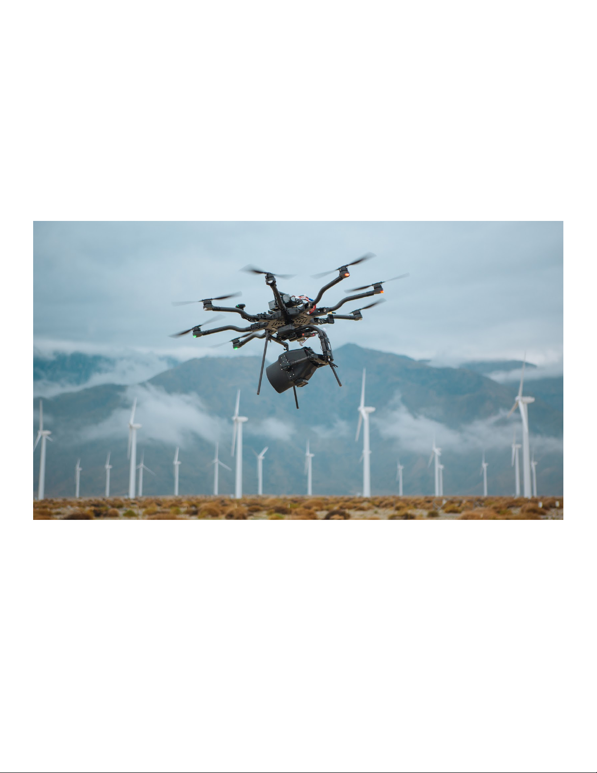
ALTA Pro is a professional multi-rotor aircraft designed for demanding cinematic,
professional, and industrial, applications. In under five minutes, ALTA Pro can unfold from its
carrying case to flying some of the most capable cinema cameras and industrial payloads on
either the top or bottom of the aircraft. ALTA Pro runs the PX4 stack and has been
customized for both cinema and commercial use, yielding precise yet smooth control.
Page 2
This Aircraft Flight Manual describes the complete operation of airframe and flight control
systems, and the normal maintenance of those items. Do not operate ALTA Pro without
reading and understanding this manual.
This manual is not a substitute for adequate flight training. Training requirements can vary
when operating in different countries or under different flight conditions. Always consult
local regulations before flying ALTA Pro. In areas where there are no flight training
requirements, it is the sole determination of the pilot-in-command as to whether he or she
has the appropriate level of training or experience for a given flight. Always set and adhere
to personal minimums and fly within your own capabilities.
Throughout the manual, warnings, cautions and notes are used to highlight various
important procedures. These are defined as follows:
Warnings are used to highlight procedures which, if not strictly observed, may result in
personal injury.
Cautions are used to highlight procedures which, if not strictly observed, may cause damage
to equipment.
Page 3
Notes are used to highlight specific operating conditions, usability tips and tricks or steps of
a procedure.
Specifications
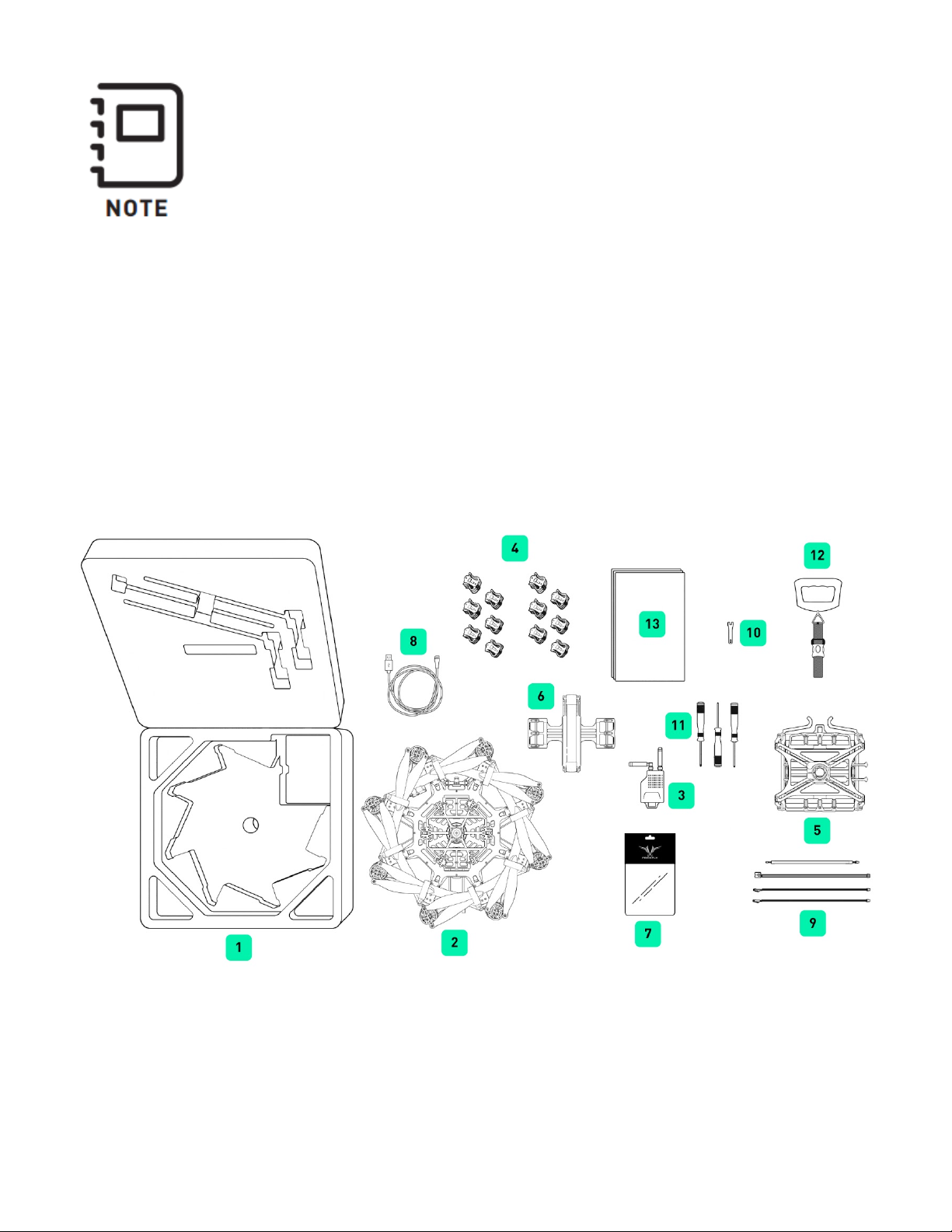
Included Items
1.
2.
Case
Page 4

ALTA Pro
3.
Long Range Radio Modem
a. Aerial portion mounted to ALTA
4.
Isolator Cartridges
a. (6) Teal (Installed)
b. (6) Black
c. (6) Red
5.
Inverted Landing Gear
6.
Quick Release Battery Tray
7.
ALTA Product Spares
8.
USB-Futaba Power Cable
9.
FPV Cables
a. Skyzone/BOSCAM
b. BOSCAM, small connector
c. ImmersionRC/Fat Shark
d. Ready Made RC
10.
5.5mm Wrench
Page 5

11.
Hex Drivers (1.5mm, 2.0mm, 2.5mm)
12.
Electronic Luggage Scale
13.
Documentation
Additional Required Components (Not Included in Base
Package)
Radio Controller
ALTA Pro supports a variety of radio controllers as outlined in the Flight Controller
Specifications. A minimum of five (5) channels are required, with four (4) used for flight
control, and the remaining one (1) used for mode selection.
A radio controller with between six to ten channels is highly recommended to
make use of Return-to-Land (RTH) and ALTA Pro’s other functions. It is
recommended to use a radio controller with a three-way switch for Mode
selection and a two-way switch for the Return-to-Land function.
Flight Battery
ALTA Pro can accommodate a variety of Lithium Polymer (LiPo) flight battery packs.
Battery packs must be 6S, having a nominal voltage of 22.2 V. Only run ALTA Pro using two
packs at a time. Each pack must have a continuous discharge rating of 250 amps or greater,
and a peak discharge rating of 500 amps or greater. For additional information on expected
flight durations, refer to the Performance Section of this manual.
Page 6

The use of flight packs which do not meet the voltage and discharge rating
above (22.2V nominal, 250a continuous discharge, and 500a peak discharge)
can cause damage to the ALTA and the batteries.
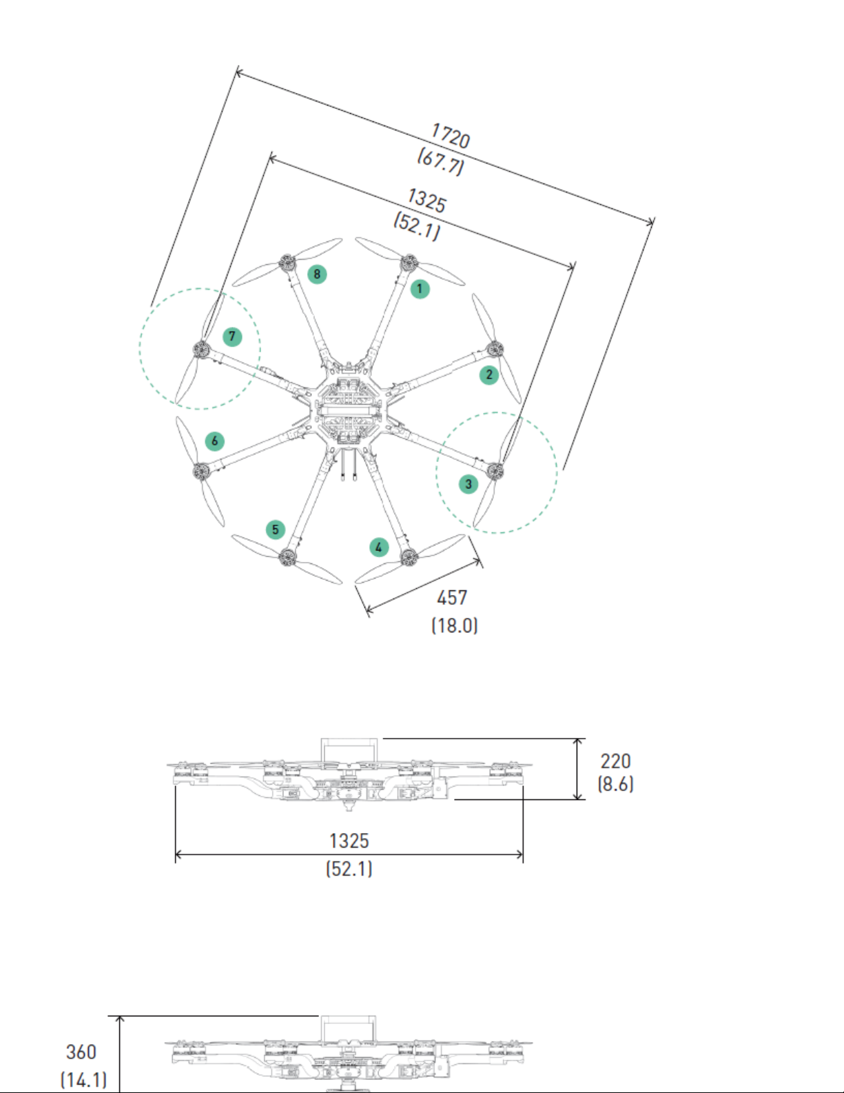
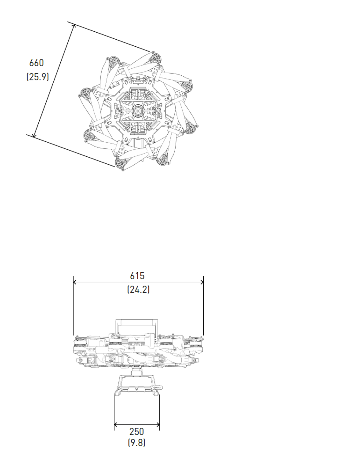
Dimensions
Item Dimension
Unfolded Diameter
1325 mm - ALTA Pro
(does not include Props)
Folded Diameter
660 mm - ALTA Pro
(does not include Props)
Height to base of Toad In The Hole (TITH) 263 mm - ALTA Pro
Page 7
Page 8

Page 9
Page 10

Powerplant
Item Specification
Number of Motors 8 - ALTA Pro 8
Motor Type Direct Drive 3-Phase PMAC Outrunner
Motor Make and Model Freefly F45
Motor Max Continuous Power Output 350 W
Motor Max Instantaneous Peak Power Output 950 W
Maximum RPM (flat rated) 6300 RPM
Equivalent Kv 384
Electronic Speed Controller Freefly Silent-Drive Sine Wave ESC
Propellers
Item Spec
Make and Model Freefly ALTA Propeller
Material Carbon fiber with balsa core
Propeller Orientation (4) CW and (4) CCW Props - ALTA Pro 8
Propeller Type 18 × 6 Folding
Battery
Item Spec
Nominal Battery Voltage 6S / 22.2V
Maximum Battery Size (GroundView) 240 × 175 × 80 mm
Maximum Battery Size (SkyView) 220 x 156 x 64 mm
Maximum Battery Quantity 2 Battery Packs (Parallel)
Minimum Battery Quantity 2 Battery Packs (Parallel)
Page 11

Item Spec
Battery Connectors 2× EC5 (Parallel)
Required Minimum Battery Discharge Rating (Per Pack) 250A / 500A Peak
Weight
Item Spec
Maximum Gross for Takeoff 18.1 kg (40.0 lbs) - ALTA Pro 8
Maximum Useful Load 12.0 kg (26.4 lbs) - ALTA Pro 8
Maximum Payload 9.1 kg (20.0 lbs) - ALTA Pro 8
Typical Standard Empty Weight 6.2 kg (13.6 lbs) - ALTA Pro 8
Specific Loadings
Item Spec
Typical Specific Power 145 W/kg
Thrust Ratio at MTOW1 1.85 : 1
Flight Controller
Item Spec
Autopilot Name PX4
Manual, Height Mode, Position Mode , Return-to-Land
Flight Modes
(RTH), Autoland, Waypoint Mission mode
Supported Inputs: DSMX, DSM2, S.Bus, S.Bus2
Supported Radios Futaba S.Bus & S.Bus2, DSMX, DSM2 (Spektrum/JR)
Supported Radio Controller
Futaba w/ built-in voltage sense port
Telemetry Systems
Minimum Radio Controller
Channels Required
5
Page 12

Item Spec
Supported GNSS GPS, GLONASS, Galileo
Supported Satellite-based
QZSS, WAAS, EGNOS, MSAS
Augmentation System
First-Person View System Video
NTSC, PAL
Formats
Supported First-Person View
Skyzone, BOSCAM, ImmersionRC, Fat Shark
Transmitters
Ready Made RC
Supported First-Person View
Cameras
First-Person View OSD Telemetry User Configurable
RMRC-700XVN (Recommended), Runcam Eagle 2 Pro,
or similar
RFD900/868X Long Range Telemetry System
Installed Transceivers
Wi-Fi 2.4 GHz b/g/n
Default Data Logging Rate 25Hz
Lighting and Indication
Item Spec
Status Light 1 Watt Red, 1 Watt White LED
Orientation Lights 3-Watt RGB LED
Orientation Light Color Options Off, Red, Orange, Yellow, Green, Blue, Cyan, Purple, White
FPV Ability FPV SD with OSD overlay
Isolation Systems
Item Spec
Page 13

Vibration Isolation System O-Rings
Option 1: Soft / Light Payloads Red O-Rings
Option 2: Medium / Medium Payloads Teal O-Rings
Option 3: Stiff / Heavy Payloads Black O-Rings
External Systems Mounting
Item Spec
FPV Transmitter Mount
Mounting Locations
Mounting System
FPV Camera Mount Between Booms 1 & 8 - ALTA Pro 8
FPV Transmitter Mount Boom 2 - ALTA Pro 8
GPS Mount Boom 7 - ALTA Pro 8
Telemetry Radio Mount Boom 3 - ALTA Pro 8
GPS Mount
Telemetry Radio Mount
Freefly Toad In The Hole (TITH) Quick Release
Dimensions / Drawing
Expansion Port Pin-outs
Page 14
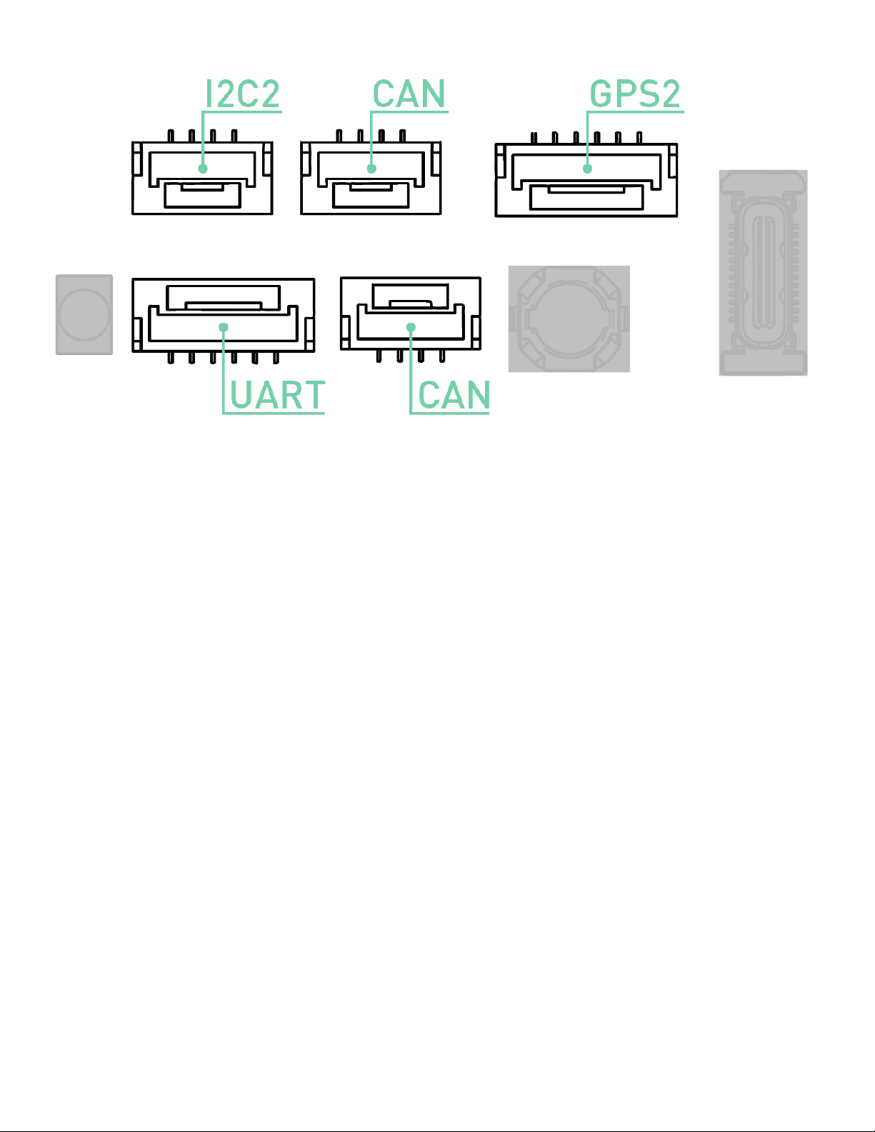
UART Port
Pin Signal Voltage (V)
1 VCC +5V
2 TX (Out) +3.3V
3 RX (In) +3.3V
4 CTS (In) +3.3V
5 RTS (Out) +3.3V
6 GND GND
GPS2 Port
Pin Signal Voltage (V)
1 VCC +5V
2 TX (Out) +3.3V
3 RX (In) +3.3V
4 I2C1 SCL +3.3V
5 I2C1 SDA +3.3V
Page 15

Pin Signal Voltage (V)
6 GND GND
CAN Ports
Pin Signal Voltage (V)
1 VCC +5V
2 CAN_H +5V
3 CAN_L +5V
4 GND GND
I2C Port
Pin Signal Voltage (V)
1 VCC +5V
2 I2C1 SCL +3.3V (1.5K pull-up)
3 I2C1 SDA +3.3V (1.5K pull-up)
4 GND GND
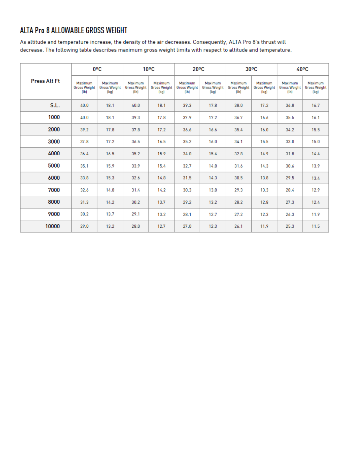
Limitations
Limitations
These limitations are advisory in nature and do not extend or restrict
limitations provided by governing aviation authorities.
Powerplant Limitations
Item Spec
Maximum RPM 6300 RPM
Page 16

Item Spec
Maximum Battery Voltage 25.2 Volts
Minimum Average Battery Voltage 19.2 Volts
Environmental Limitations
Do not fly ALTA Pro in temperatures exceeding 45ºC (113ºF) or below -20ºC(-4ºF).
Flight Controller Limits
Item Spec
Maximum Pitch/Roll Angle 45°
Maximum Yaw Rate 150° / second
Weight Limits
Item Spec
Maximum Payload 9.1 kg (20.0 lbs)- ALTA Pro 8
Maximum Takeoff Weight See following tables
ALTA 8 Pro Max Allowable Gross Weight
Page 17
Abbreviations and Terminology
Meteorological Terminology
Term Definition
Page 18

International Standard Atmosphere in which:
The air is a dry, perfect gas;
The temperature at sea level is 15° Celsius (59° Fahrenheit);
ISA
The pressure at sea level is 1013.2 mbar (29.92 inches Hg);
The temperature gradient from sea level to the altitude at which the
temperature is -56.5°C (-69.7°F) is -0.00198°C (-0.003564°F) per foot and
zero above that altitude
Mean Sea Level is the average height above the surface of the sea for all
MSL
stages of tide
AGL Above Ground Level is the height of the aircraft above the ground
Outside Air Temperature is the free air static temperature surrounding the
OAT
aircraft
Altitude measured from standard sea level pressure (1013.2 mbar, 29.92 in.
Pressure
Altitude
Hg) by a pressure or barometric altimeter
It is the indicated pressure altitude corrected for position and instrument
error. In this Manual, altimeter instrument errors are assumed to be zero
Power Terminology
Term Definition
Maximum Continuous Power
Output
Maximum Instantaneous Peak
Power Output
The maximum typical power output of a motor
averaged over the entire flight
The maximum power output of a motor during any
phase of flight, such as when maneuvering
Page 19

Flight and Powerplant Control
Term Definition
The radio controller stick responsible for throttle control. For Mode 2
Throttle Stick
Yaw Stick
Pitch Stick
Roll Stick
controllers, this is the vertical movement of the left control stick. For
Mode 1 controllers, this is the vertical movement of the right control stick
The radio controller stick responsible for yaw (also called pan) control
For Mode 2 and Mode 1 controllers, this is the lateral movement of the
left control stick
The radio controller stick responsible for pitch control. For Mode 2
controllers, this is the vertical movement of the right stick
For Mode 1 controllers, this is the vertical movement of the left stick
The radio controller stick responsible for roll control. For Mode 2 and
Mode 1 controllers, this is the lateral movement of the right control stick
Pitch/Roll Stick or
Cyclic Stick
The radio control stick responsible for both pitch and roll control
For Mode 2 controllers, this is the right stick
Weight and Balance
Term Definition
Maximum Takeoff Weight (MTOW) Maximum allowable weight at liftoff
Standard Empty Weight Weight of a standard aircraft
Basic Empty Weight Standard empty weight plus optional equipment
Difference between take off weight and basic empty
Useful Load
weight
Page 20

Term Definition
Payload Useful load less battery weight
General Terminology
Term Definition
LOS Loss of Signal
RTH Return-to-Land
Small Unmanned Aircraft System includes all components of the system required
sUAS
for the flight of an unmanned aircraft, including the radio controller, data link and
other related support equipment
Systems Diagrams
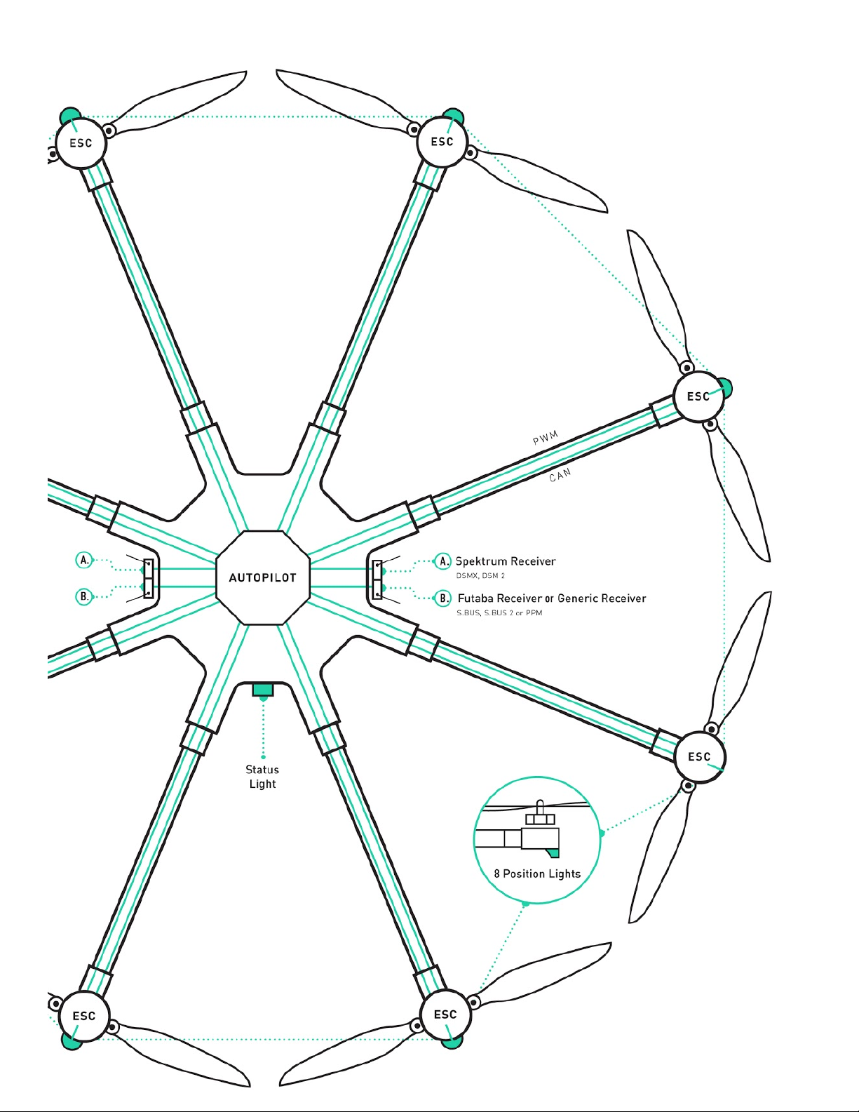
Overview
Page 21
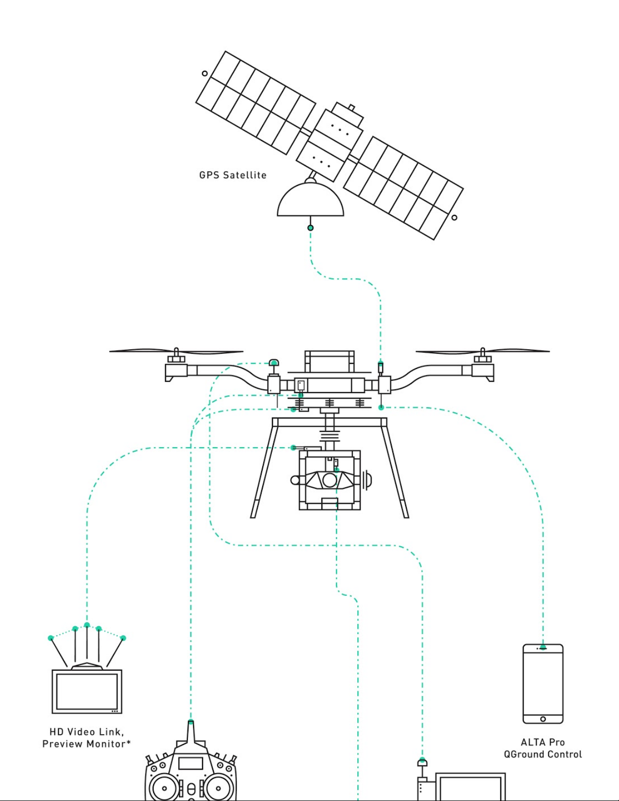
Page 22

Flight Control
****
Page 23
Page 24

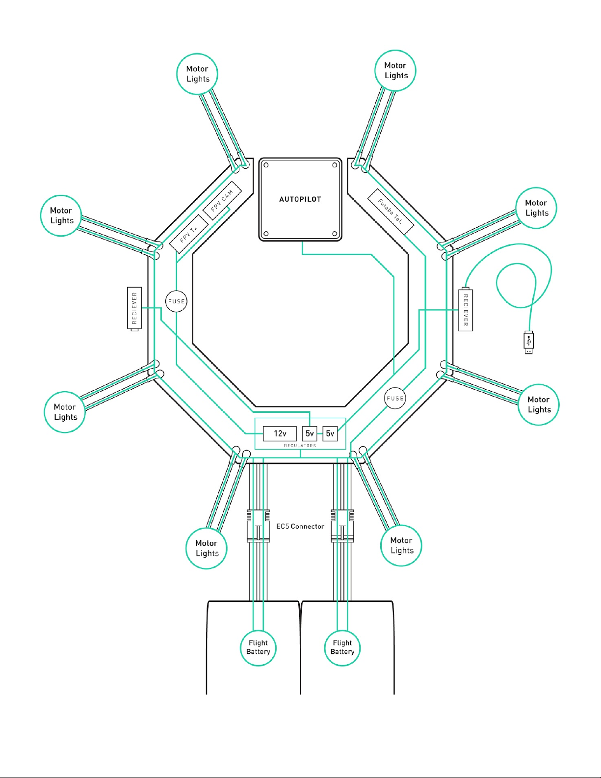
Power System
****
Page 25
Page 26

FPV Equipment
****
Page 27
Page 28

ALTA 8 Pro Ground Control Desktop and
Mobile App
Getting QGroundControl up and running is quick and easy! Use the ALTA Pro
QGroundControl program to change ALTA Pro’s parameters, monitor statuses, and set up
waypoint missions.
1.
Download and install the application.
2.
Start QGroundControl and ALTA Pro.
3.
Connect your vehicle to the ground station device.
1.
WiFi
1.
To connect to ALTA Pro via WiFi, find the ALTA Pro’s WiFi connection by
searching for it in your device’s WiFi menu and then connect to it like you
would any other device.
2.
You may have to enable the WiFi feature on ALTA Pro if it is your first time
connecting.
2.
900/868MHz
1.
Simply plug in the 900/868MHz radio into your computer using the attached
USB cable. If ALTA Pro is turned on the two radio’s will automatically
connect!
Page 29
New Features
QGroundControl
Page 30

The implementation of QGroundControl into the ALTA Pro system results in new features.
1.
By harnessing the full power of the PX4 autopilot controller architecture, ALTA Pro has
all the features of a modern drone: waypoints, autonomy, telemetry/C2, autoland, etc.
2.
Advanced, high-bandwidth position hold offers unprecedented precision, repeatability,
and stability.
3.
PX4 integration will allow users to create and fly complicated waypoints missions with
ease.
4.
The use of Mavlink and Dronecode protocol makes drone software integration possible
and creates straightforward path to custom sUAS solutions for both cinema and
business.
5.
ALTA Pro has a built in 900/868MHz radio which will allow for a range of up to 2 miles
between the aircraft and ground station.
The ALTA Pro QGroundControl App will be actively maintained, and additional functionality
may be added over time. For information on individual app updates, refer to the App release
notes.
For a more indepth review of QGroundControl’s capabilities and workflows,
please visit the QGroundControl User Guide.
Page 31

If you are currently operating with an ALTA (Autopilot) version, there is no need
to upgrade if you’re happy with the current feature set. The Autopilotcontrolled ALTA has an excellent track record for reliability and smooth flight
characteristics. Currently, the Alta Autopilot version offers Orbit mode
functionality and the Velocity clamp feature. While the ALTA Pro will continue
to see features added, it is does not currently support Orbit mode and Velocity
clamp functionality.
When flying multiple aircraft at the same time, take extreme caution to ensure
that the aircraft connected to the laptop/mobile device is the desired craft.
Failing to connect to the correct device may result in an inadvertently arming a
aircraft or disarming one that is inflight.
We suggest not selecting ‘Connect Automatically’ when using WiFi to connect
to ALTA Pro and clearly labeling each 900/868MHz RX/TX pair.
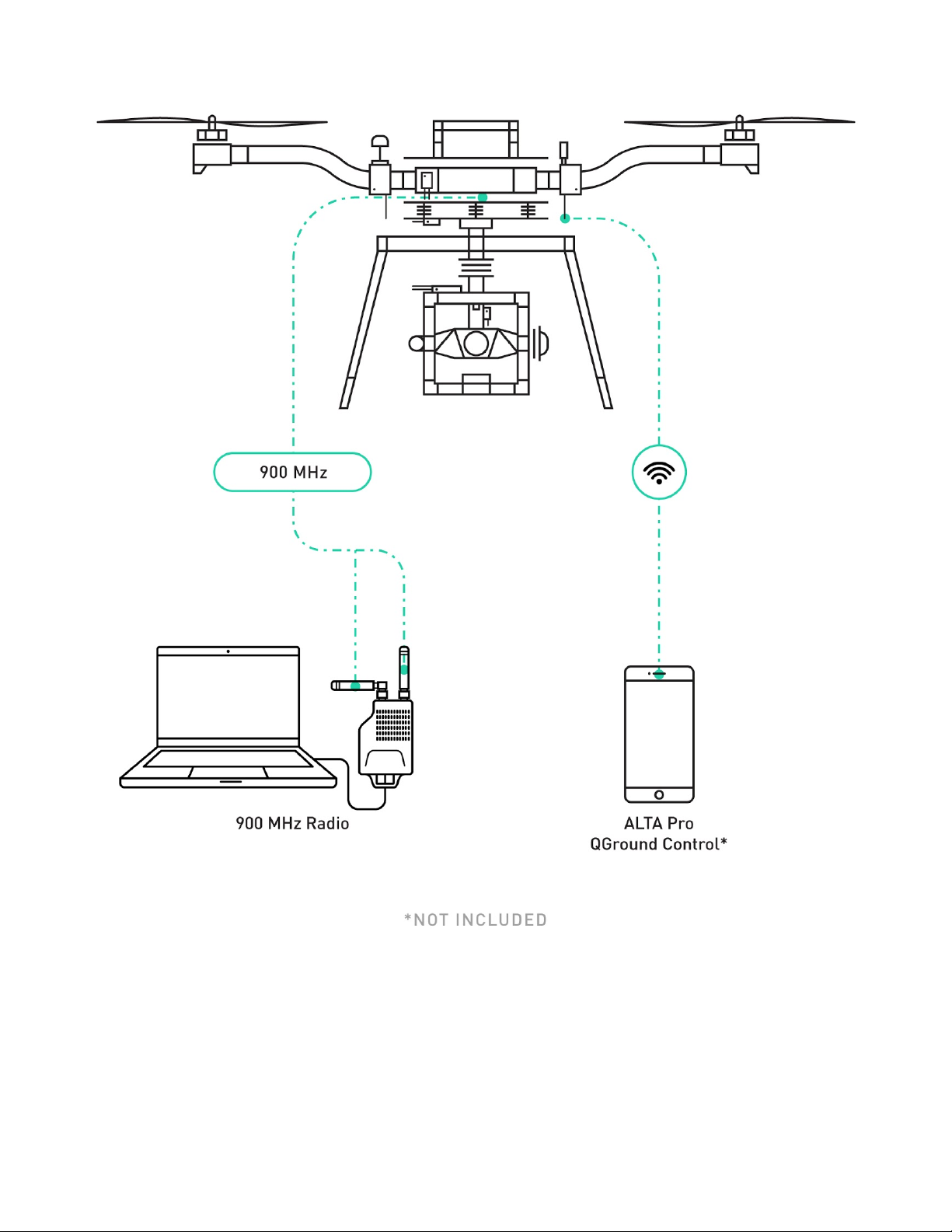
900/868 MHz Radio
ALTA Pro makes use of a 900/868MHz radio to increase the communication range between
the ALTA Pro and laptop ground station. This allows users to monitor, update, and reroute
ALTA’s while up in the air or on the move.
Page 32

All 900/868MHz radio’s are set to default signal strength when they leave our
facility. Users are responsible for making sure they are operating within the
bounds of the radio communication regulations in their area. The radio strength
settings can be updated with the RFDTools program. Users will have to use the
USB supplied with the radio modules to connect to their computer and update
signal strength parameters. This should be done for both radios. Contact
support for questions concerning how to update the radio settings.
QGroundControl Overview
Symbol Name Function
Settings Configure the QGroundControl application.
Setup Configure and tune your vehicle.
Page 33

Symbol Name Function
Plan Create autonomous missions.
Monitor you vehicle(s) while flying, including streaming
Fly
video.
Download logs, geotag images from a survey mission,
Analyze
access the MAVLink console
Click to show a dropdown of messages from the vehicle.
Vehicle Messages
GPS Status Shows you satellite count and current hdop.
RC RSSI RC signal strength information.
Telemetry RSSI Telemetry signals strength information.
Battery Remaining battery percent.
Flight Mode Current flight mode. Click to change flight mode.
This will change to a Yield sign if there are critical
messages. Yield sign shown in image above.
RTK GPS SurveyIn Status
Shows you progress of RTK GPS Survey-In process.*
*ALTA Pro does not ship with an RTK GPS
Page 34

ALTA Pro Specific QGroundControl Features
Tuning Parameters
QGroundControl has a custom tab that allows quick access to the most important ALTA Pro
parameters. These parameters are accessible through the ‘Tuning’ tab in the Vehicle Setup
Menu.
ALTA Pro Parameters
Access to boom LEDs and OSD parameters are also located in the Vehicle Setup Menu,
under the Parameters tab and in the ALTA grouping.
Setting up ALTA 8 Pro
First Time Setup
Page 35

If ALTA Pro is purchased as a bundle with a transmitter or FPV kit, these will be factory
installed and ALTA Pro will be ready to fly out of the box! For customers installing their own
receivers or FPV systems, please follow the instructions below. The guide details the first
time setup process for ALTA Pro 8.
Radio Installation
Radio Controller Receiver
ALTA Pro requires the installation of a radio control system. S.Bus, S.Bus2, DSM2, and DSMX
receiver types are supported. Some ALTA Pro emergency control modes (Return-to-Land
and Autoland) may vary depending on the type of radio. Refer to the Flight Controller Modes
section of this manual for additional details.
Additionally, ALTA Pro supports radio receiver diversity using S.Bus, S.Bus2, DSM2 and
DSMX receivers. This means two receivers may be installed, and the Autopilot flight
controller will automatically use the receiver with the best signal quality. Using two receivers
requires the radio controller to be bound to both receivers. Refer to the instructions provided
with your radio controller to complete the binding process. For Spektrum radios a receiver is
required to bind the satellites to a radio controller.
Futaba Radio for ALTA Pro 8
1.
Locate the noted closeout panels used for receiver installation (between booms 2 & 3
and 6 & 7).
Page 36

2.
Remove side closeout panel with radio wires using a 2.0mm hex driver.
3.
Plug signal wire into receiver.
4.
If using telemetry, plug the telemetry wire located in the closeout between booms 2 & 3
into the primary receiver (refer to the Voltage Telemetry section).
5.
Feed receiver antenna into lower antenna tube.
Page 37

6.
Secure receiver using the provided double-sided tape to inside of receiver housing.
7.
Reattach closeout panel.
Page 38

8.
Route antenna wires into the two antenna tubes below ALTA Pro chassis.
9.
Repeat installation process for dual receivers (if applicable).
Spektrum Radio for ALTA Pro 8
1.
Locate the noted closeout panels used for Spektrum receiver installation (between
booms 3 & 4 and 7 & 8).
Page 39

2.
Remove side closeout panel using a 2.0mm hex driver.
3.
Feed signal cable through panel grommet.
4.
Reattach closeout panel.
Page 40

5.
Plug in receiver/satellite into signal cable.
6.
Attach receiver/satellite to exterior using double-sided tape.
7.
Repeat steps 1-6 for dual receivers (if applicable).
Page 41

Voltage Telemetry
ALTA Pro supports battery voltage telemetry on Futaba radios when using a receiver that
supports an external voltage sensor, such as the R7008SB. Installing the telemetry wire is
easiest when initially installing the receiver. To set up ALTA Pro with voltage telemetry for
Futaba radios:
Installing Voltage Telemetry for ALTA Pro 8
1.
Remove the closeout panel between booms 2 and 3 with a 2.0mm hex driver and locate
the radio receiver wire bundle.
2.
Identify the voltage sense wire and connector in the bundle. It is the small, 2-pin
connector attached to a black and red wire pair.
Page 42

This wire is already connected to an in-line fuse. Soldering a fuse into this
wire is not required.
3.
Connect the cable to the voltage sense port on the primary Futaba receiver.
4.
Reattach the closeout panel.
First Person View (FPV)
Page 43

ALTA Pro can power a variety of first person view (FPV) cameras and transmitters, as well
as add informational on-screen display (OSD) elements to aid in FPV flying. Using an FPV
ground station display can be a useful method of monitoring status, performance, and flight
parameters of the ALTA Pro during flight.
Three FPV transmitter cables are included with each ALTA Pro. Each supplied cable has one
side with a connector that mates with a cable located in the closeout panel between booms
1 & 2. The other end of each supplied cable has specialty connector(s) to run Immersion RC,
Fatshark, BOSCAM, or BOSCAM compact FPV transmitters. For cable identification, refer
to the FPV Transmitter installation instructions.
A single camera cable is provided and is configured to run a Ready Made RC camera (model
RMRC-700XVN recommended). This cable mates with a pre-installed cable located behind
the closeout panel between booms 1 & 8.
Camera and transmitter cables follow this wiring scheme:
Cable Color Function
Red +12 VDC
Black Ground
Yellow Video signal
It is the responsibility of the pilot to see and avoid other aircraft, people, or
obstacles. Always maintain direct line of sight with ALTA Pro during flight, use
visual observers as operations require, and follow local regulations regarding
see-and-avoid requirements.
Page 44

Do not short the pins of the FPV transmitter connector located on the preinstalled FPV transmitter lead in the ALTA Pro. Doing so could damage the onscreen display circuit. If using a multimeter to check the pins, first connect one
of the provided transmitter cables, then take voltage readings from the
transmitter cable.
FPV System Installation
FPV Camera ALTA Pro 8
1.
FPV Camera ALTA Pro 8 Remove the front closeout panel with a 2.0mm hex driver.
2.
Locate the FPV camera cable included in the ALTA Pro package.
3.
Pass the FPV cable through the closeout panel grommet and connect to the mating
FPV camera lead inside ALTA Pro. Connect the other end directly to the camera.
4.
Replace front closeout panel.
Page 45

5.
Mount FPV camera on the FPV mount on the front ALTA Pro using the provided
hardware.
FPV Transmitter ALTA Pro 8
1.
Mount FPV transmitter on the provided carbon fiber accessory mount plate
2.
Attach accessory mount to boom 2 with M3x6 flathead bolts.
Page 46

3.
Locate the appropriate FPV transmitter cable. The following cables are included:
a. ImmersionRC/Fat Shark (cable with two connectors)
b. BOSCAM/SkyZone (cable with one large connector)
c. Compact BOSCAM (cable with one small connector)
4.
Use a pair of dykes to cut the zip tie holding the braided transmitter cable to the
corrugated tube on boom 2
Page 47

5.
Pass transmitter cable through the underside of the hinge, connect to the correct FPV
transmitter cable, and plug into the FPV transmitter.
6.
Zip tie the FPV transmitter lead to the boom 1 cable bundle and the FPV Transmitter
mount for strain relief. The boom should be fully folded when the transmitter lead is ziptied to cable bundle.
FPV On Screen Display Setup
A number of properties and components can be adjusted or added to the FPV On Screen
Display (OSD) using QGroundControl. To access these settings go to the the ALTA settings
group in the Parameters tab of the Vehicle Setup menu.
Properties
Page 48

Name Options Description
OSD_ENABLE Enabled/Disabled Turns OSD on or off
Indicates the FPV video camera
OSD_PAL_NTSC PAL / NTSC
format to PX4
OSD_UNITS Metric / Imperial Changes the displayed units
Centers the OSD components
OSD_HOR_OS Min: 1
horizontally
Centers the OSD components
OSD_VER_OS Min: 1
vertically
Controls the margin to the left of the
OSD_LEFT_OS Min: 1
OSD
Controls the margin underneath the
OSD_LOWER_OS Min: 1
OSD
Controls the margin to the right of the
OSD_RIGHT_OS Min: 1
OSD
OSD_UPPER_OS Min: 1 Controls the margin above the OSD
Sets battery cell levels that trigger an
OSD_BAT_ALARM 3.000 - 4.200
on screen warning
Min: 1.000
OSD_MAX_ALTITUDE
Default: 121.900
Min: 0.000
OSD_MAX_CLIMB
Default: 3.500
Creates an on screen warning when
exceeding the set max altitude
(meters)
Creates an on screen warning when
exceeding the set max climbing rate
(meters per second)
OSD_MAX_RANGE
Min: 1.000
Default: 1000.000
Creates an on screen warning when
exceeding the set max range (meters)
Page 49

Name Options Description
Min: 1.000
OSD_MAX_VELOCITY
Default: 20.000
OSD_GND_BRIGHT 0 - 16
OSD_SKY_BRIGHT 0 - 16
Creates an on screen warning when
exceeding the set max velocity (meters
per second)
Increases of decreases the brightness
of the ground
Increased and decreases the
brightness of the sky
Text Components
The following components are displayed as text items, and can be configured to display as
big or small letters, or no letters, effectively turning off the display.
Name Description
Displays the height of ALTA Pro from its starting point
OSD_SHOW_HEIGHT
in meters or feet
Displays the vertical speed of ALTA Pro in meters per
OSD_SHOW_VARIO
second or feet per minute
Displays the magnetic heading of ALTA Pro and is
OSD_SHOW_HEADING
measured in degrees
Displays the horizontal distance along the ground ALTA
OSD_DISTANCE
Pro is from the initialization position in meters or feet
Displays the ground speed of ALTA Pro in meters per
OSD_GROUNDSPEED
second or knots
OSD_SHOW_BATTERY Displays the voltage of the flight battery packs
OSD_SHOW_TIME Displays the time of the flight in minutes and seconds
OSD_SHOW_GPS Displays the number of GPS satellites in view
OSD_SHOW_GPSHACC
Displays the horizontal accuracy of the GPS signal in
meters or feet
Page 50

Name Description
Displays the GPS derived latitude and longitude
OSD_SHOW_LATLON
coordinates of ALTA Pro
Adds indicators to the artificial horizon that indicate
OSD_ROLL_MARKER
changes in roll
OSD_SHOW_ATT Adds an attitude indicator on screen
OSD_SHOW_BATTERY Adds a battery voltage indicator on screen
Artificial Horizon Components
The artificial horizon displays pitch and roll information in the center of the FPV display in
the form of a horizon line and accompanying elements.
Name Options Description
Off-Small-
OSD_ROLL_MARKER
Large
OSD_PITCH_SCALE 1 - 200
OSD_PITCH_IN 1 - 180
OSD_ROLL_SCALING 1 - 200
Other Components
Turns off all artificial horizon components
Allows for scaling of the artificial horizon
markings to compensate for FPV cameras of
different field views
Sets the number of degrees between pitch
markings when the artificial horizon ladder is
used
Allows for scaling of the artificial horizon
markings to compensate for FPV cameras of
different field views
The following components can be turned on or off. These components do not have
adjustable settings.
Name Description
OSD_HEADINGARROW Displays an arrow that points in the direction of north
Page 51

Name Description
Displays an arrow that points in the direction of the
OSD_HOMEARROW
initialization point
Displays a bar on the right of the screen that scales with
OSD_VARIOGFX
OSD_SPEEDGFX
OSD_SIDESLIPGFX
vertical speed. The bar will increase in length up to indicate a
climb, or down to indicate a descent
Displays a bar on the left of the screen that scales with the
forward/rearward velocity component
The bar will extend up to indicate forward velocity, or down
to indicate a rearward velocity
Displays a bar on the bottom of the screen that scales with
the side-to-side velocity component
The bar will extend left to indicate leftward velocity, or right
to indicate rightward velocity
Unfolding and Folding ALTA
ALTA Pro features swan-neck booms that fold compactly for travel. They are secured in an
open position for flight using over-center latches.
Unfold ALTA Pro
1.
Remove ALTA from case.
2.
Unfold ALTA Pro Remove ALTA from case. Fold down all six/eight boom retention clips.
Page 52

3.
Open ALTA Pro booms. ALTA Pro can become unbalanced and tip over while unfolding
booms individually, so unfold opposite boom pairs simultaneously to keep balance.
4.
Snap shut all eight boom latches until they click and latch.
Page 53

5.
Visually confirm all latches are seated properly
6.
Remove prop protectors.
Page 54

Fold ALTA Pro
Secure props with prop protectors.
2.
Unlatch all eight booms.
Page 55

3.
Close ALTA Pro booms in opposing pairs to keep balance.
4.
Fold up all eight boom retention clips to secure booms.
Page 56

Care should be taken when storing ALTA Pro in its case to avoid damaging the
GPS antenna and the telemetry radio. When storing ALTA Pro in a nonstandard case, remove all antennas to ensure there is minimal/no contact
between the external electronics and the case.
Radio Calibration and Channel Mapping
ALTA Pro can be used with a variety of radio controllers. Different radio controllers can map
functions to different channels, so properly mapping controller channels to ALTA Pro
functions is an important step before flying. Radio calibration and channel mapping are
performed using the ALTA Pro QGroundControl program or app.
If you are uncertain about your radio channel mapping, obtain assistance from an
experienced pilot or from Freefly Customer Support.
Calibrating Radios Using ALTA Pro QGroundControl App
Calibrating any compatible radio is done using the ALTA Pro QGroundControl app. This only
needs to be done when using a new radio with the ALTA Pro; ALTA Pros that were bought
with a radio have already gone through the Calibration and Mapping procedures.
Power the ALTA Pro by plugging in a USB-C cable to the expansion port.
The expansion port is located under the closeout between booms 1 and
Once connected, the ALTA electronics will be powered and you may turn on the radio.
Open the ALTA QGroundControl program, navigate to the Radio tab in the Vehicle
Setup menu, and then initiate the radio calibration.
Page 57

Make sure to reset all trims and subtrims to zero before
continuing with calibrating and mapping your radio.
Set the transmitter mode radio button that matches your radio configuration (this
ensures that QGroundControl displays the correct stick positions for you to follow
during calibration).
Move the sticks to the positions indicated in the text (and on the radio image). Press
Next when the sticks are in position. Repeat for all positions.
When prompted, move all other switches and dials through their full range (you will be
able to observe them moving on the Channel Monitor).
Press Next to save the settings.
Mapping Channels Using ALTA Pro QGroundControl App
Radio channel mapping is accomplished with the Alta Pro Qgroundcontrol App. Prior to
mapping channels, ensure your radio controller and receivers are properly installed and
calibrated. Refer to the Radio Installation section of this manual and your radio controller’s
documentation.
Power the ALTA Pro by plugging in a USB-C cable to the expansion port. The expansion
port is located under the closeout between booms 1 and 2
Once connected, the ALTA electronics will be powered and you may turn on the
transmitter.
Open the ALTA QGroundControl program, navigate to the Flight Mode tab in the
Vehicle Setup menu for access to the channel mapping.
Channel mapping can be customized by the user on this menu to fit their preferences.
Below is a quick description of the items mapped to the transmitter and suggested
channels for each mapped item.
Page 58

Function Descriptions
The following functions can be mapped to radio controller channels. These are found in the
Radio section of the Configurations menu in ALTA QGroundControl. Each function is also
represented by a chart that responds to control input allowing for quick verification of
mapping settings.
Controller
Use this to select the appropriate receiver. The following guide is compiled for convenience.
For complete specifications and which mode will work with your receiver, refer to your radio
controller or receiver manuals. DSM2/DSMX are typically used by Spektrum controllers
SBUS is typically used by Futaba controllers
Pitch/Roll/Yaw/Throttle
The Pitch, Roll, Yaw and Throttle controls are the basic flight controls and are mapped to the
two radio controller sticks.
Mode
The required Mode Switch selects between the three different flight modes: Manual,
Altitude, and Position. A three-position switch is recommended to select the three different
modes. However, a two-position switch may be used, but will only allow for selecting
between Manual Mode and (depending on radio controller mixes) either Altitude Mode or
Height Mode
Return to Home Switch
The optional Return to Home Switch selects between the different Return-to-Land (RTH)
functions. At minimum a two-position switch is required for the Home Switch functions to
select between RTL Off, and initiate RTL functions.
Page 59

Typical Channel Mappings
The following radio channel mapping configurations are recommendations only and can be
set in ALTA QGroundControl. Depending on exact radio models, these may help as an initial
configuration. However, it is up to the pilot setting up ALTA Pro for flight to determine if
these settings are appropriate.
Futaba 14SG/8FG
Function Channel Number Direction
Pitch 2 Normal
Roll 1 Normal
Yaw 4 Normal
Throttle 3 Reverse
Mode Switch 5 Normal
Home Switch 6 Normal
Page 60

Spektrum DX18
Function Channel Number Direction
Pitch 3 Reverse
Roll 2 Reverse
Yaw 4 Reverse
Throttle 1 Normal
Mode Switch 6 Reverse
Home Switch 7 Normal
Page 61

Configuring for MōVI
MōVI can be attached to either the top or bottom of ALTA Pro via the Freefly Toad In The
Hole (TITH) quick release.
ALTA Pro comes pre-configured for GroundView mounting of MōVI.
Groundview
Prepare your MōVI for GroundView flight (see MōVI manual)
Attach landing gear
Install TITH receiver on MōVI
Page 62

Connect MōVI to bottom Toad
Skyview
****
Prepare your MōVI for SkyView flight.
Remove landing gear (see MōVI manual)
Install TITH receiver on MōVI (see MōVI manual)
Connect and secure the supplied inverted landing gear to the bottom Toad.
Top mounting is not supported by the MōVI M10 without the keyed pan tube
upgrade kit. If you are unsure whether your M10 has the upgrade kit, contact
Freefly Customer Support for additional info.
Page 63

Remove Battery Mount Quick Release.
****
Connect MōVI to top Toad.
Page 64

Isolator Cartridges
Isolator Cartridges
Different Isolator Cartridges can be used to fine tune vibration damping performance for
different payload weights or ambient temperatures. Three isolation cartridge styles are
provided with ALTA Pro. The cartridges have colored o-rings: red for light payloads or cold
ambient temperature, teal for medium payloads or typical ambient temperature, and black
for heavy payloads or hot ambient temperature. Flight testing may be required to determine
the optimal isolator for a given setup.
****
Page 65

To install, place the cartridges between the top chassis plate and the battery plate. Ensure
they are engaged in the track features and are parallel with the chassis and battery plate.
Push inwards fully until they click, indicating the cartridges are locked in place. Pull outwards
on the cartridge to ensure it is locked.
Always ensure isolator cartridges are locked in place before flying ALTA Pro.
Isolator cartridges that are not locked can cause the payload to loosen and
change ALTA Pro’s fundamental flying characteristics.
****
Page 66

To remove, pinch the cartridge latch to unlock it from the battery and chassis plate, and
slide it outwards to disengage. Simultaneously pull the battery and chassis plate apart while
pulling the cartridge outward.
Battery Installation
Battery Installation
Batteries may be installed on either the top or bottom of an ALTA Pro and are always
mounted opposite of the payload location. In both locations, battery packs are secured with
silicone straps tensioned across the packs. The straps are secured using studs located on
either side of the packs.
Page 67

Always secure battery packs with both battery retention straps.
Ensure both battery packs are at a similar state of charge (a full pack voltage
difference less than 0.5V) prior to connecting them to ALTA Pro. Plugging in
two dissimilarly charged packs could cause one pack to rapidly discharge into
the other and damage the batteries or cause a battery fire.
Only use packs that are identical in their capacity and at a similar condition.
Using a pack with another that is larger, or has many more charge/discharge
cycles, can damage the battery packs.
Always refer to and follow the battery manufacturer’s instructions,
recommendations and guidelines for battery handling.
When plugging in battery packs, ensure the polarity is correct. Positive is
indicated by a red power lead, and negative/ground is indicated by a black
power lead. Reversing polarity will damage ALTA Pro’s electronics.
Groundview
1.Place battery retention strap studs at the appropriate height to hold the battery packs
firmly in position.
2.
Adjust battery stops to fit battery packs.
Page 68

3.
Attach the single-hole end of the battery retention straps to the studs.
4.
Place battery packs on the battery tray.
Page 69

5.
Tension and secure battery retention straps.
Skyview
Do not install batteries directly on the lower battery tray if a Toad adapter
is also installed. Either remove the Toad adapter or use the Quick Release
Battery Tray.
****
Always completely secure the inverted landing gear by closing the TITH quick
release lever. Inverted landing gear that are not completely attached can
rotate and unplug battery leads.
1.
Pinch the battery tray handles and slide to remove it from landing gear.
Page 70

2. Attach the single-hole ends of the battery retention straps to the studs on the battery
tray.
3.
Place battery packs onto battery tray.
4.
Tension and secure battery retention straps.
5.
Slide tray with battery packs back into landing gear until the tray latches in place.
Page 71

6.
Ensure tray and battery packs are secure.
Sensor Calibration
ALTA Pro features a highly sensitive 3-axis magnetometer, gyroscope, and accelerometer
that measure specific force, angular rate, and earth’s magnetic field to infer heading and
maintain stability. Occasionally, the sensors will require recalibration.
ALTA Pro’s compass should be regularly calibrated, especially when traveling
between different geographic locations. For best results, it is recommended to
perform manual compass calibrations away from ferrous objects, buildings and
vehicles. In addition, concrete can contain steel rebar which may influence
compass calibrations
Page 72

Perform calibration without a payload attached and all motor booms
extended and latched. Folded booms will cause an inaccurate calibration.
It is recommended to use two people to perform the compass calibration as
it requires handling and rotating ALTA Pro.
To perform sensor calibrations on ALTA Pro:
1.
Mount a pair of batteries onto ALTA Pro.
2.
Plug in the batteries to power up the aircraft.
3.
Open the ALTA Pro QGroundControl and connect to ALTA Pro.
4.
Navigate to the Sensors tab under Vehicle Setup.
5.
Available sensors are displayed as a list of buttons beside the sidebar. Sensors marked
with green are already calibrated. Sensors marked with red require calibration prior to
flight.
6.
Click on the button for each sensor to start its calibration sequence and follow the
instructions provided in the ALTA Pro QGroundControl.
7.
Start by selecting Set Orientations and set the autopilot orientation
1.
Autopilot Orientation: ROTATION_YAW_270
Page 73

Page 74

Compass Calibration
Follow the instructions below to perform a compass calibration on ALTA Pro. Compass
calibrations should be done when flying in a new location or when ALTA Pro QGroundControl
prompts a calibration.
1.
Click the Compass sensor button.
2.
Click OK to start the calibration.
3.
Place the vehicle in any of the orientations shown in red (incomplete) and hold it still.
Once prompted (the orientation-image turns yellow), rotate the vehicle around the
specified axis in either/both directions. Once the calibration is complete in that
orientation the associated image on the screen will turn green.
4.
Repeat the calibration process for all vehicle orientations.
Page 75

Accelerometer Calibration
Follow the instructions below to perform an accelerometer calibration on ALTA Pro.
Accelerometer calibrations should only be done when prompted by ALTA Pro
QGroundControl.
1.
Click the Accelerometer sensor button.
2.
Click OK to start the calibration.
3.
Position the vehicle as guided by the images on the screen. This is very similar to
compass calibration.
Page 76

Level Horizon Calibration
Follow the instructions below to perform a level horizon calibration on ALTA Pro. Horizon
calibrations should only be done if the horizon (as shown in the HUD) is not level after
completing Accelerometer calibration.
1.
Click the Level Horizon sensor button.
2.
Place the vehicle in its level flight orientation on a level surface.
3.
Click OK to start the calibration.
Propellers
Page 77

The folding propellers include two balanced carbon fiber propeller blades attached to
propeller hubs, which are themselves secured to the motors. The propellers installed on
booms 1, 3, 5, and 7 spin clockwise when viewed from above ALTA Pro, and the propellers
installed on booms 2, 4, 6, and 8 spin counterclockwise when viewed from above.
For information on propeller installation and maintenance, refer to the Maintenance section
of this manual.
Only use propellers supplied by Freefly on ALTA Pro. Use of third-party
propellers can cause motor instability, overheating, and failure.
In rare cases propellers can experience icing, this occurs when ice begins to
form on the tips and underside of the blades due to temperature and humidity.
This will cause the props to become unbalanced, increases drag and reduces
lift. Flying with iced blades can be dangerous and is not advised
Page 78

Checking Propeller Bolt Tightness
****
Page 79

****
Over time, the bolts that hold the propeller blades to the propeller hub can loosen due to
vibration. To check propeller bolt tightness, twist the propeller about its length. If there is
free play, the propeller bolt is too loose. Use the provided 2.5mm hex driver and wrench to
tighten the bolt and nut that secure the propeller blade just enough to remove the play.
Do not overtighten, or the propeller may fail to unfold completely during
motor start up, leading to excessive vibration.
Tuning ALTA Pro's Flight Controller
ALTA Pro’s Flight Controller comes pre-tuned for a wide variety of payloads and flying
conditions. Generally, additional tuning is not required to fly ALTA Pro, and will only need to
take place if more customization of control feel is desired. Default tuning values are included
in Appendix A, Default Tuning Values.
Page 80

DO NOT CHANGE FLIGHT CONTROLLER TUNING VALUES WITHOUT A FULL
UNDERSTANDING OF THE TUNING PROCESS. A poorly tuned sUAV is
dangerous and can result in property damage, injury, and death.
Parameters fall into three categories: Rate, Attitude, and Position. Typically, tuning should
take place in that order, ensuring Rate parameters are set first, then moving to Attitude
parameters, and finally Position parameters.
Before tuning, users should read and become familiar with the PX4 Tuning Guide.To tune
ALTA Pro, open the ALTA Pro QGroundControl connect to your ALTA Pro and navigate to
the Multicopter Attitude Control and Multicopter Position Control parameters groups under
the Parameter Tab in the Vehicle Setup menu. Once you have found the parameter pages
follow the instructions in the PX4 Tuning Guide.
Page 81

****
Tuning can change the fundamental flying characteristics of ALTA Pro. It is
possible for ALTA Pro to become unstable or even uncontrollable if values are
set too high or too low. Only change tuning parameters in small increments and
with caution. Always test new tuning configurations in open areas away from
people or obstacles.
While ALTA Pro QGroundControl allows users to tune their ALTA Pro in the
air we suggest changing tuning values while ALTA Pro is on the ground as a
precautionary measure.
When making configuration changes with ALTA Pro QGroundControl, make
sure to save each parameter as you change them!
Additional Parameters
Additional Parameters
ALTA Pro QGroundControl allows users to alter many additional parameters that do not
affect the Flight Controller characteristics of ALTA Pro. These parameters are used to select
neutral points using trim or to set maximum or minimum values for a variety of different
settings. These settings can be found under the Tuning and Parameters tabs in the Vehicle
Setup menu.
Users should understand the effect of parameter settings before changing
them. Incorrect or poorly chosen parameters can result in crashes, injury, or
death. You can always reset all parameters to defaults by following the
Reset to Default instructions.
Page 82

Use the search bar at the top of the Parameters tab to quickly find any settings!
ALTA Configuration Setup
We have compiled a list of the most important ALTA Pro Flight parameters in the Tuning
Tab under the Vehicle Setup Menu. Ensure you have an understanding of what the
characteristic of the ALTA Pro a parameter effects before changing it.
You may need to update the Hover Throttle when changing payloads to
optimize ALTA Pro’s flight performance. The Hover Throttle settings can be
found under the ALTA Configuration Setup tab or in the Parameters tab.
If you are unsure of what characteristics a parameter effects please reach
out to Freefly’s Customer Support Team for clarification.
Safety Parameters
QGroundControl allows users to customize ALTA Pro’s fail safes and safety parameters.
These options are found under the Safety tab in the Vehicle Setup menu.
Low Battery Parameters
This set of parameters allows users to select when battery levels warnings are triggered and
what the aircrafts failsafe is when this threshold is met.
RC and Datalink LOS Failsafe Settings
Page 83

This parameter determines the flight mode ALTA Pro will enter if it detects a Loss-of-Signal
(LOS). Selecting ‘Land at Current Position’ will cause ALTA Pro to Autoland in place when
the LOS is detected. Selecting ‘Return to Land’ will cause ALTA Pro to Return-to-Land and
then Autoland when the LOS is detected.
Return Home Settings
Used to set the RTL altitude, loiter time, and RTL behavior.
Land Mode Settings
This adjusts the descent rate of the ALTA Pro during Autoland in meters per second. This
value is applied to the Autoland descent profile for the final 15 meters above the ground until
landing. This option also provides the option to automatically disarm ALTA Pro after landing.
Saving, Loading, and Resetting Parameters
Saving, Loading, and Resetting Parameters
ALTA Pro QGroundControl allows users to save, load, and reset all of ALTA Pro’s
parameters. This is useful when trying to save certain parameters that will need to used
again in the future or when troubleshooting and needing to get back to a known good state.
Page 84

Saving Parameters
Saving parameters can be done in the Parameters tab of the Vehicle Setup menu. Navigate
to the ‘Tools’ menu in the top right hand corner of the window and select ‘Save to file…’ from
the dropdown. Then select a file name and folder to save to.
Loading Parameters
Loading parameters is also done from the Parameters tab of the Vehicle Setup menu.
Navigate to the ‘Tools’ menu in the top right hand corner of the window and select ‘Load
from file…’ from the dropdown. Then select the desired .params file to load.
Resetting Parameters
To reset all ALTA Pro’s parameters to the ALTA Pro defaults follow the Loading Parameters
instructions and load the ALTA Pro Default Parameters file. This can be found on the ALTA
Pro support page.
Page 85

Selecting the ‘Reset all to defaults’ option in the Tools menu will reset all
parameters to the QGroundControl defaults. These are not the same as the
ALTA Pro default parameters. To reset to ALTA Pro defaults load the ALTA
PRO Default Parameters to the aircraft.
Updating your Wifi Password and SSID
Enabling and Updating Your Wifi Password and SSID
1.
Connect to ALTA Pro using the Radio Modem or USB
2.
Go to the System Parameters under the Parameter tab in the Vehicle Setup menu and
find the SYS_COMPANION parameter.
3.
Change the SYS_COMPANION parameter to ‘ESP8266 (921600 baud, 8N1)’ and restart
ALTA Pro to enable the WiFi connection.
To enable WiFi connectivity follow the steps below!
Please read this entire section if you intend to use the WiFi feature of ALTA
Pro.
When flying multiple aircraft with WiFi enabled, take extreme caution to
ensure that the aircraft connected to the laptop/mobile device is the desired
craft. Failing to connect to the correct device may result in an inadvertently
arming a aircraft or disarming one that is inflight.
ALTA Pro allows users to update the system’s WiFi password and SSID. All ALTA Pro’s
initially come with WiFi disabled for safety reasons.
Page 86

Once you have enabled ALTA Pro’s WiFi, change the password and SSID from their defaults!
1.
Connect to ALTA Pro’s WiFi using the initial password listed below
1.
SSID: [off] AltaPro-<serial number>; eg. [off] AltaPro-781880
2.
Password: altaalta
2.
Open your prefered web browser and go to 192.168.4.1
3.
Select setup, then update the SSID and password. Make sure to make the password is
eight characters long, secure, and noted down somewhere in case you forget!
1.
Do not change any of the other menu items!
ALTA Pro passwords must be longer than eight characters and should be
unique for each ALTA Pro. Do not use the same password on multiple
machines!
Page 87

Page 88

We suggest not selecting ‘Connect Automatically’ when using WiFi to
connect to ALTA Pro and clearly labeling each 900/868MHz RX/TX pair.
4.
Once the password and SSID have been updated, hit the save button at the bottom of
the menu.
5.
Power cycle ALTA Pro and ensure you can connect to ALTA pro using the new
password.
6.
Connect to Futaba radio system and confirm both receivers work and system arms.
Operating ALTA Pro
Flight Controller Modes
Flight Controller Modes
Overview
ALTA Pro has three primary flight control modes which are selected using the Mode Switch:
Manual Mode, Altitude Mode, and Position Mode. ALTA Pro also has two emergency control
modes, Return-to-Land and Autoland, which are available only during certain situations. For
additional information, refer to the sub-section associated with each emergency control
mode.
Altitude Mode and Position Mode are assistive only and are not a replacement
for pilot skill and ability. Pilots should be proficient in Manual Mode flight in
order to react to emergency situations as required.
Page 89

Always center the control input sticks on the radio controller when switching
between control modes to prevent unexpected movement of the ALTA Pro.
Manual Mode
In Manual Mode, ALTA Pro will only stabilize its attitude. At neutral control input (middle
pitch and roll stick position), ALTA Pro will attempt to remain level. Throttle control is direct.
Altitude Mode
Altitude Mode changes the throttle stick behavior to command climb and descent rates. The
higher the throttle stick position, the faster ALTA Pro will climb. Conversely, the lower the
throttle stick position, the faster ALTA Pro will descend.
When the throttle stick is centered, ALTA Pro will enter Altitude Hold. In Altitude Hold, ALTA
Pro will maintain a target altitude and try to correct for drift. If a disturbance moves ALTA
Pro away from this target altitude, ALTA Pro will climb or descend to return to the target
altitude.
Altitude Mode is assistive only and is not a replacement for pilot skill and
ability. Pilots should be proficient in Manual Mode flight in order to react to
emergency situations as required.
Position Mode
Position Mode changes the pitch/roll stick behavior to command ground speeds. Pitch and
roll stick deflection will command fore/aft and left/right ground speeds respectively.
Controlling altitude in Position Mode is the same as in Altitude Mode.
Page 90

With pitch and roll controls centered, ALTA Pro will enter Position Hold. In Position Hold,
ALTA Pro will maintain its position over a given point on the ground and correct for
disturbances.
Position Mode requires a strong GPS signal and communication with a minimum of 6
satellites. If a weak signal is present, ALTA Pro will not enter Position Mode. If the GPS signal
degrades while in Position Mode, ALTA Pro will automatically revert to Manual Mode.
Within Position Mode ALTA Pro enters Classic Control style which use the tuning parameters
to control translational position over the ground.
Position Mode is assistive only and is not a replacement for pilot skill and
ability. Pilots should be proficient in Manual Mode flight in order to react to
emergency situations as required.
Flight using Position Mode in areas of degraded GPS signal, such as near
buildings or under dense tree cover, is not recommended. The automatic
reversion to Manual Mode can cause unexpected, abrupt changes in flight
behavior.
Flight using Position Mode with Compass enabled in areas near large ferrous
objects or high magnetic flux is not recommended. Incorrect compass readings
can result in loss of control. Compass assist can be disabled in the ALTA App if
desired.
Waypoints Mode
Waypoints mode allows ALTA Pro to execute a predefined autonomous waypoint missions
that have been uploaded to the flight controller via ALTA Pro QGroundControl (QGC). For
more information on all of the different options and abilities built into the Waypoint
functionality you can read more in the PX Literature.
Page 91

ALTA Pro must have a GPS lock on its home position in order to start a
waypoints mission.
Return-to-Land
Return-to-Land Mode will command ALTA Pro to fly back to the defined Home Point. When
ALTA Pro first acquires a GPS position, it sets this as the Home Point of the flight. See the
Radio Channel Mapping section in this manual for more information on setting up the
Return-to-Land Switch.
RTL can be initiated automatically with an LOS event if it is selected as the Signal Loss
Action in the ALTA App. RTL can also be initiated manually while flying in Position Mode and
setting the Home Switch to RTH.
Full functionality of the PX4 LOS features is only available on an
S.Bus/S.Bus2 or DSM2/DSMX receiver.
When initiated manually using the Home Switch, ALTA Pro will fly back to the Home Point.
ALTA Pro will hover above the home point and wait for a set amount of time and then land.
The pilot can cancel the RTL procedure by returning the Home Switch to the middle or
bottom position.
During an LOS event, RTL followed by Autoland will be initiated automatically if ‘RTL’ is
selected as Signal Loss Action in the ALTA App and an S.Bus/S.Bus2 or DSM2/DSMX radio
system is in use. ALTA Pro will first check its current altitude against Safe Height. If ALTA
Pro is below the Safe Height, it will climb to Safe Height. If ALTA Pro is above Safe Height, it
will remain at its current altitude. Next, ALTA Pro will fly back to the home position at the
RTL Speed set in the ALTA Pro QGroundControl. Finally, upon reaching the home position,
ALTA Pro will loiter for 15s and then begin to Autoland.
Page 92

Autoland
Autoland will only initiate if one of the following conditions is met and the Autoland is setup
as the failsafe for these events. See the Safety Parameters to customize ALTA Pro’s failsafe
behaviors:
Loss of Signal (LOS) occurs and ‘Land’ is selected as the Signal Loss Action in the ALTA
app
At the end of a LOS Return-to-Land event when using S.Bus/S.Bus2 or DSM2/DSMX
radio systems
Battery exhaustion failsafe is tripped and the failsafe is set to return to land in ALTA
Pro QGroundControl.
Autoland and Return-to-Land will only occur if these settings are turned on
in the aircraft parameters. Geofences
Geofences
Geofences are currently not supported by Freefly. We recommend that you do not use this
feature. If this feature is used, set the Geofence breach action to Warning; Hold, RTL, and
Page 93

Terminate should not be used as they may result in crash or an ALTA Pro that cannot return
to its home position.
Home Switch
The home switch has three positions, however only the top toggle position will turn RTL on.
RTL Off
(Bottom/Middle Toggle Position)
This is the normal switch position and does not initiate an RTL command.
RTL On
(Top Toggle Position)
This manually initiates the RTL function. In RTL, PX4 will command ALTA Pro to climb to the
set minimum altitude and then guide the unit’s position to the home point.
Once RTL has been initialized it will continue to return to home unless the
Home Switch is returned to RTL Off.
Status Light
Page 94

The rear-facing Status Light shows the status of ALTA Pro as it boots, arms, and flies. The
following table shows the different meanings of the light in the various flight phases.
Flight Phase Light Color Meaning
Flashing Red +
Booting
White
Standby Flashing White Flight controller is running and disarmed
Flashing Red Flight controller is running and not ready to arm
Solid Red Flight controller boot unsuccessful
Armed Off Ready for Flight
Flight - all modes Solid Red Flight critical alarm—land immediately!
Flight controller is booting
Page 95

Flight Phase Light Color Meaning
Flight - Manual
Off
Mode
Solid White
Solid Red
Flashing Red Battery land voltage—land immediately!
Flight - Height Hold Off
Slow Flashing White Height hold active
Nominal flight status
No errors
Outside user-defined range, height, or speed
limits
Flight critical alarm or battery alarm
voltage—land immediately!
Nominal flight status
Height hold inactive
Solid or Flashing
Red
Flight - Position
Off
Hold
Fast Flashing White Height Hold and Position Hold Active
Solid or Flashing
Red
Orientation Lights
Flight critical alarm—land immediately!
Nominal flight status
Height hold inactive
Position hold inactive
Flight critical alarm —land immediately!
Page 96

The boom-end mounted Orientation Lights indicate both the orientation of ALTA Pro in
flight and the status of the individual motor Electronic Speed Controllers (ESCs) during
other operational phases. The following table shows the different meanings of the light
colors in the various operational phases.
Flight Phase Light Color Meaning
Standby Flashing Green ESC booted normally
Armed User-defined Nominal Status
Flight User-defined Nominal Status
Firmware Update Pink ESC firmware is updating
Alarms
Page 97

ALTA Pro will notify the pilot of critical alarms through QGroundControl. These alarms
indicate a serious issue has been observed in the behavior of the ALTA Pro that, if not acted
upon immediately, can cause loss of control. Never continue a flight when ALTA Pro indicates
an alarm!
Aircraft Monitor
ALTA Pro QGroundControl includes a flight status monitor that displays information about
the health of the ALTA Pro and the various controls that can be selected.
Icon Name Description
Indicates if the PX4 has completed its booting process and
Boot
Battery Displays the voltage of the battery packs.
Status Displays the state of the PX4 flight controller.
Radio
GPS Displays if PX4 has resolved a GPS fix or not.
Sats
Lock
whether it was successful. Any issues that prevented a normal
boot are indicated here.
Displays if the PX4 detects a radio controller signal. A LOS
warning is displayed if no signal is present.
Displays the number of GPS satellites in view and being received.
A minimum of 6 satellites are required in order to enter Position
Mode.
Clicking on this icon displays whether a position lock is ready,
indicating a valid GPS fix and good heading. This is required
Altitude
before the Autopilot will allow switching into Position Mode.
Displays the current height control mode: Manual, Vario if in
Height or Position mode and climbing or descending, and Hold.
Page 98

Icon Name Description
Attitude Displays the current attitude control mode.
Displays the status of the compass and if the Autopilot believes
the compass readings are good or bad. If Bad, the compass may
Compass
require recalibration (see the Compass Calibration section in this
manual).
Speed Displays ground speed.
Flight Time
Displays the amount to time the aircraft has been flying.
Data Logging
ALTA Pro automatically logs flight and control data when ALTA Pro is armed for flight. Data
is recorded to the autopilot and are accessed through the Log Download tab in the Analyze
menu of ALTA Pro QGroundControl.
Page 99

Summarized flight data from an individual flight can also be viewed immediately after
landing by placing a downloaded log file into PixHawk Flight Review. Full details about the
review process can be found in the Flight Reporting section of the Pixhawk User Manual.
A native data analyzer is being developed and will be available on the ALTA Pro Support
page.
Normal Procedures
Unpacking and Setup
Unpacking and Setup
Item Action
1. Aircraft REMOVE from case
2. Prop protectors REMOVE
Page 100

Item Action
3. Boom retention clips STOW
4. Booms UNFOLD
5. Boom latches LOCK
6. Receivers and wiring CHECK
7. Isolator cartridges SELECT and INSTALL as necessary
8. Payload mounting location CONFIGURE as necessary
To set up ALTA Pro for flight, remove it from the case, and remove the prop protectors.
Stow the boom retention clips by folding them down. The clips fold in one direction and are
spring-loaded to stay in open and closed detented positions.
Unfolding the booms is most easily accomplished by unfolding all opposite pairs partially,
then unfold the opposite boom pairs completely. ALTA Pro can become unbalanced while
unfolding booms individually, so unfolding opposite pairs reduces the possibility of tipping.
Once unfolded, push on the boom latches until they audibly click, indicating the booms are
secure. There should be little to no slop in the hinge. Check that the receivers and the
electrical connectors that attach to the receivers are secure.
For information on installing isolator cartridges and setting up payload mounting locations,
refer to the Isolator Cartridges and Configuring GroundView or SkyView sections of this
manual.
Before Starting
Item Action
1. Payload SECURED
2. Isolator Cartridges VERIFY SECURE
3. Propellers CHECK CONDITION, VERIFY TIGHT
4. Propeller Hubs VERIFY SECURE
5. Motors CHECK CONDITION
 Loading...