

Page 1
AIRCRAFT FLIGHT MANUAL
77000042 | REVISION D | 01.16.2017
Page 2

REVISION HISTORY
REVISION DATE DESCRIPTION
A July 2015 Initial Release
B August 2015 Revised section order. Added Allowable Gross Weight table.
C October 2015 Revised for clarity. Added Disarm Safety function and WiFi password
reset information. Revised default tuning values to reflect SYNAPSE
version 3.4.
D January 2017 Added discussion of features available in SYNAPSE version 4.0.4. Added
Kinematic Position Mode. Added Orbit Mode. Updated Alarm Light
scenarios. Added procedure to disable ceiling and range limits. Updated
Autoland descent rate. Updated default settings, switch functions, and
data logging fields. General updates and typographical fixes. Revised
name to ALTA 6. Added additional maintenance items, motor alignment
process, additional troubleshooting information. Fixed errata.
ALTA 6 AIRCRAFT FLIGHT MANUAL
DOCUMENT NUMBER: 77000042
Page 3

CONTENTS
2 Revision History
3 Table of Contents
6 ALTA 6 OVERVIEW
7 Disclaimer and Warning
9 Limitation of Liability
10 Introduction
11 Symbols, Abbreviations, and Terminology
14 Dimensions
16 Included Items
17 Specifications
21 Limitations
23 System Diagrams
27 ALTA Mobile App
28 Additional Required Components (not included)
29 SETTING UP ALTA 6
30 Unfolding/Folding ALTA 6
33 Radio Installation
38 Radio Channel Mapping
44 Configuring for MōVI
46 Isolator Cartridges
47 Battery Installation
52 Compass Calibration
55 Propellers
57 First Person View (FPV)
64 Tuning ALTA 6
68 ALTA 6 Flight Parameters
72 Resetting ALTA 6 WiFi Password
73 OPERATING ALTA 6
74 Flight Controller Modes
79 Home Switch
3| AIRCRAFT FLIGHT MANUAL
Page 4

80 Orbit Switch
81 Disarm Safety Switch
82 Status Light
84 Orientation Lights
85 Alarms
86 ALTA App Monitor
87 Data Logging
88 NORMAL PROCEDURES
89 Unpacking and Setup
90 Before Starting
92 Before Takeoff
94 After Every Flight
96 After Last Flight
97 EMERGENCY PROCEDURES
98 Emergency Guidance
99 Alarm Indication (Flashing or Solid Red Light)
100 Pilot Loss of ALTA 6 Orientation
101 Unexpected Flight Controller Behavior
102 Battery Exhaustion
103 Radio Loss of Signal (LOS)
104 Loss of FPV Signal
105 PERFORMANCE
106 Weight / Endurance Performance Data
107 Allowable Gross Weight Gross Weight
108 MAINTAINING ALTA 6
109 General Information and Techniques
110 Maintenance Items
114 Firmware Update Process
115 Motor Alignment
118 Guidelines Following an Accident
4| AIRCRAFT FLIGHT MANUAL
Page 5

119 TROUBLESHOOTING
124 APPENDIX
125 Appendix A. Default Tuning Values
126 Appendix B. Data Logging Fields
5| AIRCRAFT FLIGHT MANUAL
Page 6
ALTA 6 OVERVIEW
6| AIRCRAFT FLIGHT MANUAL
Page 7

DISCLAIMER AND WARNING
IMPORTANT - Please read this disclaimer and warning carefully and review
the ALTA 6 Aircraft Flight Manual (AFM) prior to flight. If you have any questions,
please contact support@freeflysystems.com prior to using the ALTA 6. You can review
the most current version of this AFM at www.freeflysystems.com/software-manuals/.
By using ALTA 6, you acknowledge that you have read, understand and agree to this
disclaimer. You agree that you are solely responsible for your conduct while using
ALTA 6, and for any direct or indirect consequences that may result from its use. You
agree to only use ALTA 6 for proper purposes that are in accordance with local and
airspace rules and regulations.
» ALTA 6 is not a toy and should be operated with extreme care, as improper
operation can cause damage to property, serious personal injury or death.
» As with any multi-rotor aircraft, ALTA 6 is a complex and technical ma-
chine. Novice pilots should invest sufficient time on a flight simulator and
seek training from an experienced pilot prior to operation. The ALTA 6 Aircraft Flight Manual and a flight simulator are no substitute for training with
an experienced pilot, particularly when it comes to learning how to safely
operate ALTA 6. Novice pilots should never fly without the supervision of an
experienced pilot.
» Always check ALTA 6 and its components prior to operation.
» Always maintain a safe distance from ALTA 6 when in use.
» Never attempt to touch ALTA 6 when the propellers are moving.
» Never fly ALTA 6 over or around people, power lines or other aircraft.
» Never fly with any propellers that have visible imperfections or damage.
» Always keep children and animals a safe distance away from ALTA 6 when
in use and when changing configurations.
» Only use propellers supplied by Freefly Systems that are designed for use
on ALTA 6.
» Always remove the propellers or power ALTA 6 using a low power source
when making a change to the configuration of ALTA 6 to prevent propeller
strikes in the event of unintentional motor starts.
» Always remove the configuration jumper when making changes to the
configuration of ALTA 6.
» Always test ALTA 6 with the propellers removed to make sure that the mo-
tors are spinning in the correct direction and that the motor assignment is
correct with respect to the SYNAPSE flight controller. If you have either of
these wrong, the ALTA 6 will be uncontrollable and dangerous.
» It is your responsibility to perform a full system check of ALTA 6 prior to
every flight.
» It is your responsibility to learn how to safely operate ALTA 6 and to adhere
7| AIRCRAFT FLIGHT MANUAL
Page 8

to all applicable rules and regulations.
» Fly at your own risk.
» ALTA 6 is a tuned system with custom components selected for each appli-
cation. Modification to, removal, or substitution of ALTA 6 components will
void the warranty and can lead to unsafe operating conditions.
8| AIRCRAFT FLIGHT MANUAL
Page 9

LIMITATION OF LIABILITY
IN NO EVENT SHALL FREEFLY BE LIABLE TO BUYER FOR ANY INDIRECT,
CONSEQUENTIAL, PUNITIVE, INCIDENTAL, OR SPECIAL DAMAGES, OR ANY DAMAGES
WHATSOEVER RESULTING FROM THE USE OF ALTA OR FROM LOSS OF USE, DATA
OR PROFITS (HOWEVER CAUSED AND UNDER ANY THEORY OF LIABILITY), EVEN
IF FREEFLY HAS BEEN ADVISED OF THE POSSIBILITY OF SUCH DAMAGES. IN NO
EVENT SHALL FREEFLY’S LIABILITY FOR A PRODUCT (WHETHER ASSERTED AS A
TORT CLAIM, A CONTRACT CLAIM OR OTHERWISE) EXCEED THE AMOUNTS PAID TO
FREEFLY FOR SUCH PRODUCT. NOTWITHSTANDING ANYTHING HEREIN, IN NO EVENT
SHALL FREEFLY’S LIABILITY FOR ALL CLAIMS ARISING OUT OF OR RELATING TO THIS
AGREEMENT EXCEED THE AMOUNTS PAID BY BUYER TO FREEFLY FOR PRODUCT IN
THE LAST TWELVE (12) MONTHS. IN NO EVENT WILL FREEFLY BE LIABLE FOR COSTS
OF PROCUREMENT OR SUBSTITUTE GOODS BY BUYER. THE LIMITATIONS SET FORTH
HEREIN SHALL APPLY TO ALL LIABILITIES THAT MAY ARISE OUT OF THIRD-PARTY
CLAIMS AGAINST BUYER. THESE LIMITATIONS SHALL APPLY NOTWITHSTANDING ANY
FAILURE OF ESSENTIAL PURPOSE OF ANY LIMITED REMEDY.
Freefly shall not be liable for damages or injuries incurred directly or indirectly from the
use of ALTA 6 including, but not limited to, the following situations:
» Failure of operator to follow proper instructions and safety warnings found at
www.freeflysystems.com.
» Failure of the operator to understand and operate the aircraft within the
operating limitations described in this manual.
» Failure of the operator to follow onboard safety warnings while using ALTA 6.
» Failure of the operator to follow and comply with local rules and
regulations.
» Failure of the operator to inspect ALTA 6 and its components prior to operation.
» Failure of the operator to properly maintain and/or service ALTA 6 through an
authorized Freefly Service Center with genuine ALTA 6 parts.
» Use of third-party products on ALTA 6.
» Use of ALTA 6 in a physically or mentally impaired capacity.
» Use of ALTA 6 without sufficient training.
» Use of ALTA 6 in unsafe conditions, including but not limited to, bad or severe
weather, such as rain, wind, snow, lightning, dust storms, etc., or in areas of
magnetic or radio interference, such as power stations, broadcasting and cell
phone towers, government prohibited airspace, etc.
» Improper operation, misjudgment or risky behavior while using ALTA 6.
» Infringement of third party data, audio or video rights recorded when using
ALTA 6.
9| AIRCRAFT FLIGHT MANUAL
Page 10

INTRODUCTION
ALTA 6 is a professional multi-rotor aircraft designed for demanding
cinematic, television, and photographic applications. Within five
minutes, ALTA 6 can unfold from its carrying case to flying some of
the most capable cinema cameras on either the top or bottom of the
aircraft. The SYNAPSE flight controller is purpose-built for cinema
use, yielding precise yet smooth control.
This Aircraft Flight Manual has been prepared to describe the
complete operation of airframe and flight control systems, and the
normal maintenance of those items. Do not operate ALTA 6 without
reading and understanding this manual.
This manual is not a substitute for adequate flight training. Training
requirements can vary when operating in different countries or
under different flight conditions. Always consult local regulations
before flying ALTA 6. In areas where there are no flight training
requirements, it is the sole determination of the pilot-in-command
as to whether he or she has the appropriate level of training or
experience for a given flight. Always set and adhere to personal
minimums and fly within your own capabilities.
10| AIRCRAFT FLIGHT MANUAL
Page 11
SYMBOLS, ABBREVIATIONS, AND TERMINOLOGY
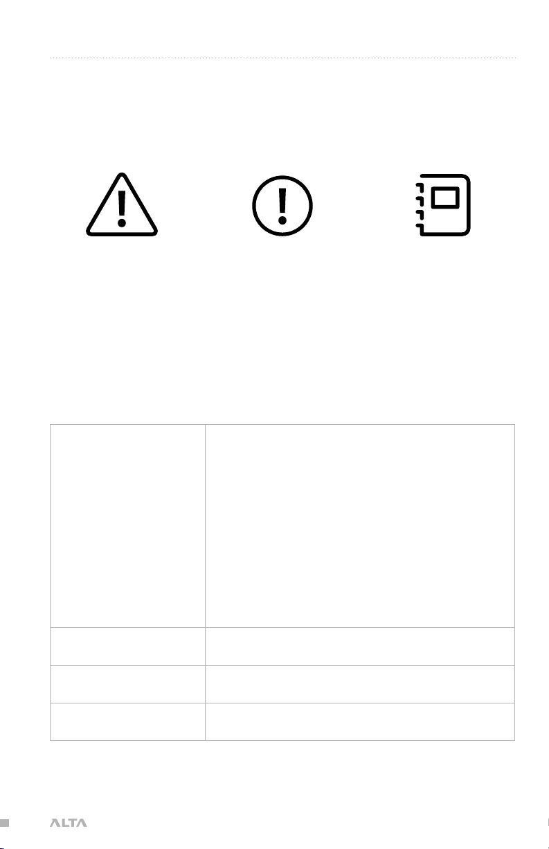
WARNINGS, CAUTIONS AND NOTES
Throughout the manual, warnings, cautions and notes are used to highlight various
important procedures. These are defined as follows:
WARNING
Warnings are used to highlight procedures which, if not strictly observed,
may result in personal injury or loss
of life.
CAUTION
Cautions are used to highlight procedures which, if not strictly observed,
may cause damage to equipment.
NOTE
Notes are used to highlight specific
operating conditions or steps of a
procedure.
METEOROLOGICAL TERMINOLOGY
ISA International Standard Atmosphere in which:
The air is a dry, perfect gas;
The temperature at sea level is 15°
Celsius (59° Fahrenheit);
The pressure at sea level is 1013.2
mbar (29.92 inches Hg);
The temperature gradient from sea level
to the altitude at which the temperature is
-56.5°C (-69.7°F) is -0.00198°C (-0.003564°F)
per foot and zero above that altitude
MSL Mean Sea Level is the average height above
the surface of the sea for all stages of tide
AGL Above Ground Level is the height of
the aircraft above the ground
OAT Outside Air Temperature is the free air static
temperature surrounding the aircraft
11| AIRCRAFT FLIGHT MANUAL
Page 12

Pressure Altitude Altitude measured from standard sea level
pressure (1013.2 mbar, 29.92 in. Hg) by a
pressure or barometric altimeter
It is the indicated pressure altitude corrected for
position and instrument error. In this Manual,
altimeter instrument errors are assumed to be zero
POWER TERMINOLOGY
Maximum Continuous
Power Output
Maximum Instantaneous
Peak Power Output
The maximum typical power output of a
motor averaged over the entire flight
The maximum power output of a motor during
any phase of flight, such as when maneuvering
FLIGHT AND POWERPLANT CONTROL
Throttle Stick The radio controller stick responsible for
throttle control. For Mode 2 controllers, this
is the vertical movement of the left control
stick. For Mode 1 controllers, this is the
vertical movement of the right control stick
Yaw Stick The radio controller stick responsible
for yaw (also called pan) control
For Mode 2 and Mode 1 controllers, this is the
lateral movement of the left control stick
Pitch Stick The radio controller stick responsible for
pitch control. For Mode 2 controllers, this is
the vertical movement of the right stick
For Mode 1 controllers, this is the
vertical movement of the left stick
Roll Stick The radio controller stick responsible for roll
control. For Mode 2 and Mode 1 controllers, this is
the lateral movement of the right control stick
Pitch/Roll Stick
or Cyclic Stick
The radio control stick responsible
for both pitch and roll control
For Mode 2 controllers, this is the right stick
12| AIRCRAFT FLIGHT MANUAL
Page 13
WEIGHT AND BALANCE
Maximum Takeoff
Weight (MTOW)
Standard Empty Weight Weight of a standard aircraft
Basic Empty Weight Standard empty weight plus optional equipment
Useful Load Difference between take off weight
Payload Useful load less battery weight
Maximum allowable weight at liftoff
and basic empty weight
GENERAL TERMINOLOGY
LOS Loss of Signal
RTH Return-to-Home
sUAS Small Unmanned Aircraft System includes all
components of the system required for the flight of
an unmanned aircraft, including the radio controller,
data link and other related support equipment
13| AIRCRAFT FLIGHT MANUAL
Page 14
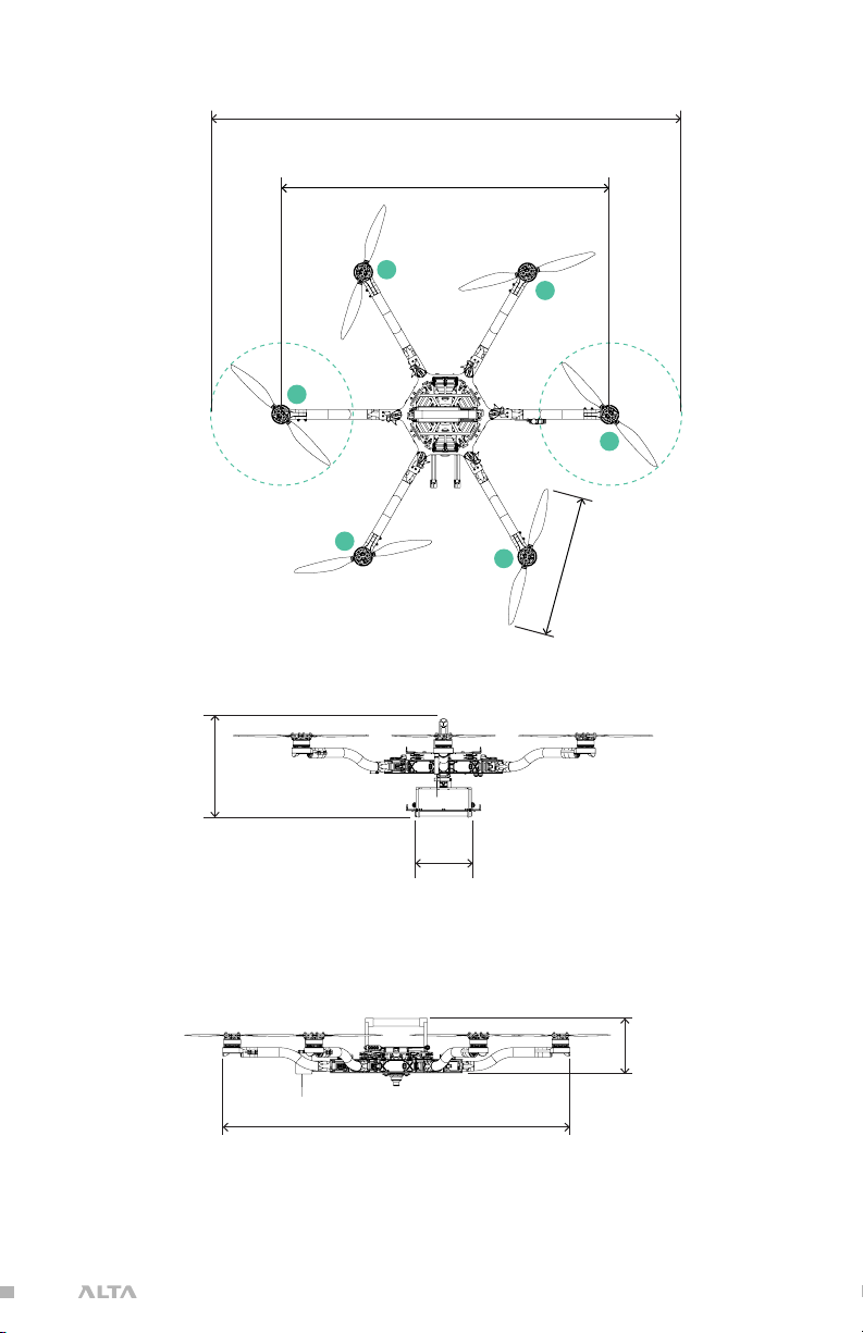
DIMENSIONS
457
(18.0)
1064
(41.9)
178
(7.0)
1126
(44.3)
1533
(60.4)
1
2
3
4
5
6
457
(18.0)
1064
(41.9)
1533
(60.4)
1
2
3
4
5
6
1533
(60.4)
1064
(41.9)
6
1
5
2
4
3
457
(18.0)
UNFOLDED PLAN VIEW WITH BOOM NUMBERING SCHEME MM (INCH)
318
(12.5)
180
(7.1)
UNFOLDED SIDE VIEW WITH LANDING GEAR MM INCH
1126
(44.3)
178
(7.0)
UNFOLDED FRONT VIEW WITHOUT LANDING GEAR MM INCH
14| AIRCRAFT FLIGHT MANUAL
Page 15
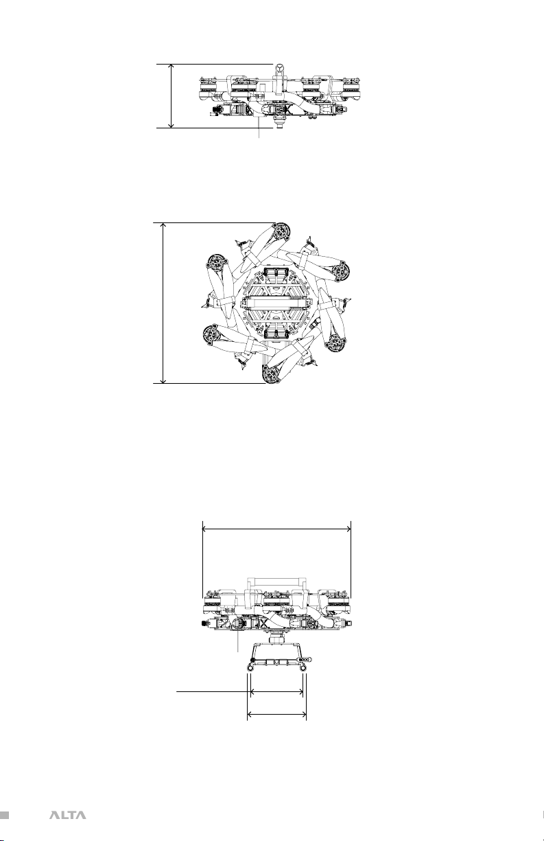
550
(21.7)
515
(20.3)
180
(7.1)
205
(8.1)
220
550
(21.7)
(8.7)
FOLDED SIDE VIEW MM INCH
550
(21.7)
FOLDED PLAN VIEW MM INCH
180
(7.1)
FOLDED FRONT VIEW MM INCH
515
(20.3)
205
(8.1)
15| AIRCRAFT FLIGHT MANUAL
Page 16
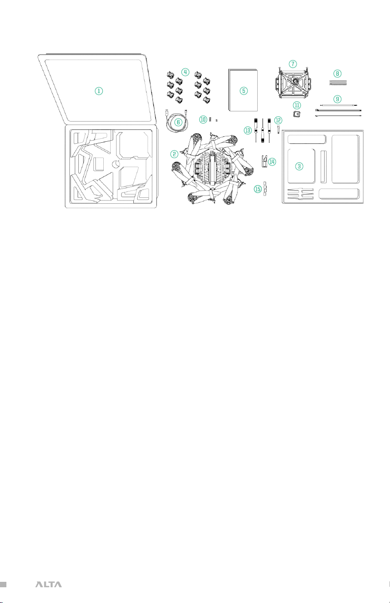
INCLUDED ITEMS
1. Case
2. ALTA 6
3. Case Lid Foam
4. Isolator Cartridges
a. (6) Teal (Installed)
b. (6) Black
c. (6) Red
5. Documentation
6. USB-Futaba Power Cable
7. Inverted Landing Gear
8. Anten n a Tub e s
9. FPV Cables
a. Skyzone/BOSC AM
b. BOSCAM, small connector
c. ImmersionRC /Fat Shark
d. Ready Made RC
10. Fasteners
a. (4) M3 × 8 Socket Head for
Toad In The Hole Male Adapter
b. (2) M3 × 8 Flat Head for Accessory
Mount
11. Toad In The Hole Male Adapter
12. 5.5mm Wrench
13. Hex Drivers (1.5mm, 2.0mm, 2.5mm)
14. Accessory Mount
15. Double-Sided Tape
16. Electronic Luggage Scale
16| AIRCRAFT FLIGHT MANUAL
Page 17

SPECIFICATIONS
DIMENSIONS
Unfolded Diameter
(does not include Props)
Folded Diameter
(does not include Props)
Height to base of Toad In The Hole (TITH) 220 mm
POWERPLANT
Number of Motors 6
Motor Type Direct Drive 3-Phase PMAC Outrunner
Motor Make and Model Freefly F45
Motor Max Continuous Power Output 350 W
Motor Max Instantaneous
Peak Power Output
Maximum RPM (flat rated) 6300 RPM
Equivalent Kv 384
Electronic Speed Controller Freefly Silent-Drive Sine Wave ESC
1126 mm
550 mm
950 W
PROPELLERS
Make and Model Freefly ALTA Propeller
Material Carbon fiber with balsa core
Propeller Orientation (4) CW and (4) CCW Props
Propeller Type 18 × 6 Folding
BATTERY
Nominal Battery Voltage 6S / 22.2V
Maximum Battery Size (GroundView) 240 × 175 × 80 mm
Maximum Battery Size (SkyView) 220 x 156 x 64 mm
Maximum Battery Quantity 2 Battery Packs (Parallel)
Minimum Battery Quantity 2 Battery Packs (Parallel)
Battery Connectors 2× EC5 (Parallel)
Required Minimum Battery
Discharge Rating (Per Pack)
200A / 400A Peak
17| AIRCRAFT FLIGHT MANUAL
Page 18
WEIGHTS
Maximum Gross for Takeoff
Maximum Useful Load
Maximum Payload
3
Typical Standard Empty Weight: 4.5 kg (10.0 lbs)
WARNING
Always refer to the following aircraft limitations section for
complete information on allowable maximum gross weights
at different altitudes and temperatures before any flight.
1
2
13.6 kg (30.0 lbs)
9.1 kg (20.0 lbs)
6.8 kg (15.0 lbs)
SPECIFIC LOADINGS
Typical Specific Power
Thrust Ratio at MTOW
1
At sea level, ISA. Refer to the Weight Limitations section for complete loading
information.
2
Top and bottom mount. Includes batteries.
3
Payload weight top or bottom mount. Battery weight not included and mounted on
opposite side from payload.
4
At MTOW, sea level, ISA.
4
1
145 W/kg
1.85 : 1
18| AIRCRAFT FLIGHT MANUAL
Page 19

FLIGHT CONTROLLER
Model Name Freefly SYNAPSE flight controller
Flight Modes Manual, Height Mode, Position Mode
(Classic, Kinematic), Return-to-Home
(RTH), Autoland, Orbit Mode
Supported Inputs: DSMX, DSM2, S.Bus,
S.Bus2, PPM, FPV SD
Supported Radios Futaba S.Bus & S.Bus2, DSMX,
DSM2 (Spektrum/JR), PPM,
PPM Invert, PPM Graupner
Supported Radio Controller
Telemetry Systems
Minimum Radio Controller
Channels Required
Supported GNSS GPS, GLONASS, Galileo
Supported SBAS QZSS, WAAS, EGNOS, MSAS
First-Person View System
Video Formats
Supported First-Person
View Transmitters
Supported First-Person View Cameras Ready Made RC
Futaba w/ built-in voltage sense port
NTSC, PAL
Skyzone, BOSCAM,
ImmersionRC, Fat Shark
5
(RMRC-700XVN Recommended)
First-Person View OSD Telemetry User Configurable
Installed Transceivers Wi-Fi 2.4 GHz b/g/n
Data Logging Rate 25 Hz
LIGHTING AND INDICATION
Status Light 1 Watt Red, 1 Watt White LED
Orientation Lights 3-Watt RGB LED
Orientation Light Color Options Red, Yellow, Blue, Purple,
Green, White, Off
ISOLATION SYSTEM
Vibration Isolation System O-Rings
Option 1: Soft / Light Payloads Red O-Rings
Option 2: Medium / Medium Payloads Teal O-Rings
Option 3: Stiff / Heavy Payloads Black O-Rings
19| AIRCRAFT FLIGHT MANUAL
Page 20

PAYLOAD MOUNTING
Mounting Locations Bottom and Top Mount
Mounting System Freefly Toad In The Hole
(TITH) Quick Release
FPV Camera Mount Forward, underneath chassis
FPV Transmitter Mount Boom 5
20| AIRCRAFT FLIGHT MANUAL
Page 21
LIMITATIONS
NOTE
These limitations are advisory in nature and do not extend or
restrict limitations provided by Governing Aviation Authorities.
POWERPLANT LIMITATIONS
Maximum RPM 6300 RPM
Maximum Battery Voltage 25.2 Volts
Minimum Average Battery Voltage 19.2 Volts
ENVIRONMENTAL LIMITATIONS
Do not fly ALTA 6 in temperatures exceeding 45ºC (113ºF) or below -20ºC(-4ºF).
FLIGHT CONTROLLER LIMITS
Maximum Pitch/Roll Angle 45°
Maximum Yaw Rate 150° / second
5
5
Battery temperature ratings must be observed.
21| AIRCRAFT FLIGHT MANUAL
Page 22
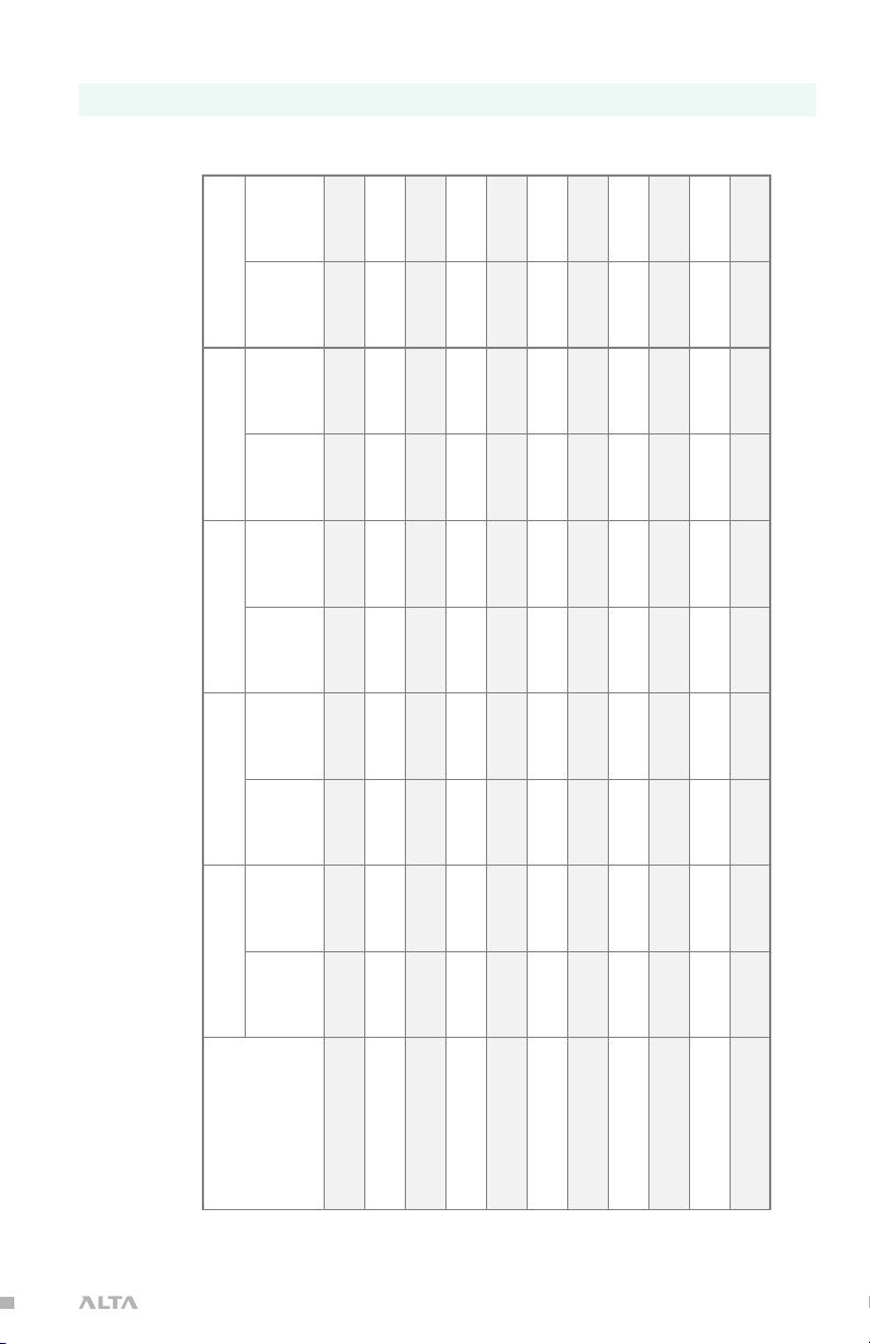
WEIGHT LIMITS
As altitude and temperature increase, the density of the air decreases. Consequently, ALTA’s thrust will decrease. The following
Maximum Payload 6.8 kg (15.0 lbs)
Maximum Takeoff Weight See following table
9.7
9.3
8.9
19.7
9.2
20.4
9.6
8.6
19.0
8.9
19.6
9.2
(kg)
Maximum
Gross Weight
(lb)
Maximum
Gross Weight
(kg)
Maximum
Gross Weight
(lb)
Maximum
Gross Weight
(kg)
Maximum
Gross Weight
12.5
27.6
12.9
28.5
13.4
12.1
26.6
12.5
27.5
12.9
11.6
25.7
12.0
26.5
12.4
11.2
24.7
11.6
25.5
12.0
10.8
23.8
11.2
24.6
11.5
10.4
23.0
10.8
23.7
11.1
10.0
22.1
10.4
22.8
10.7
21.3
10.0
22.0
10.3
20.5
9.6
21.2
9.9
ALLOWABLE GROSS WEIGHT
table describes maximum gross weight limits with respect to altitude and temperature.
(lb)
Maximum
Gross Weight
(kg)
Maximum
Gross Weight
(lb)
Maximum
Gross Weight
(kg)
Maximum
Gross Weight
0ºC (32ºF) 10ºC (50º) 20ºC (68ºF) 30ºC (86ºF) 40ºC (104ºF)
(lb)
Maximum
Gross Weight
Press Alt Ft
29.5
28.4
13.6
13.4
30.0
29.4
13.6
13.6
30.0
30.0
Sea Level
305m (1000ft)
27.4
26.4
25.5
12.9
12.4
12.0
28.4
27.4
26.4
13.3
12.9
12.4
29.4
28.4
27.3
610m (2000ft)
914m (3000ft)
1219m (4000ft)
24.5
23.6
22.7
11.5
11.1
10.7
25.4
24.5
23.5
11.9
11.5
11.1
26.3
25.4
24.4
1524m (5000ft)
1829m (6000ft)
2134m (7000ft)
21.9
21.1
20.3
9.9
10.3
22.7
10.7
23.5
2438m (8000ft)
9.5
21.8
21.0
9.9
10.3
22.6
21.8
2743m (9000ft)
3048m (10000ft)
22| AIRCRAFT FLIGHT MANUAL
Page 23
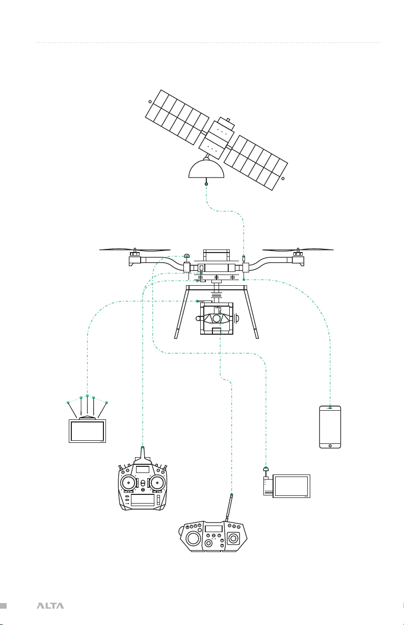
SYSTEM DIAGRAMS
sUAS OVERVIEW
GPS Satellite
HD Video Link,
Preview Monitor*
*NOT INCLUDED
Radio Controller*
2.4GHz Mō VI Controller*
FPV Rx,
Preview Monitor*
ALTA App
23| AIRCRAFT FLIGHT MANUAL
Page 24
FLIGHT CONTROL
ESC
A. Spektrum Receiver
DSMX, DSM 2
B. Futaba Receiver or Generic Receiver
S.BUS, S.BUS 2 or PPM
SYNAPSE
Flight
Controller
A.
B.
Status
Light
PWM
ESC
CAN
6 Position Lights
ESC
24| AIRCRAFT FLIGHT MANUAL
Page 25
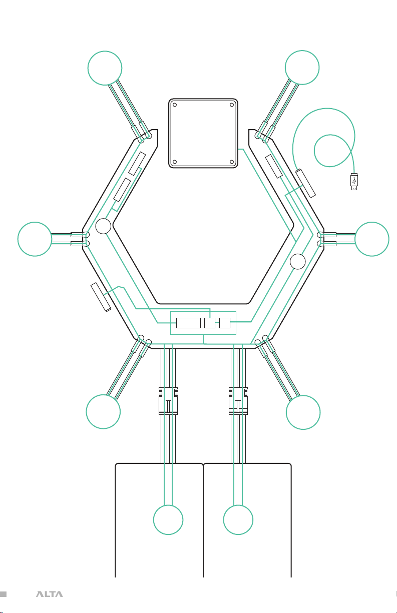
POWER SYSTEM
Motor
Lights 5*
Motor
Lights 6*
FUSE
RE C EI V ER
FP V T x FP V C AM
SYNAPSE
Flight
Controller
12v 5v
REGULATORS
Motor
Lights1 *
Fu tba Te l.
RE C EI V ER
Motor
Lights 2*
FUSE
5v
Note: Do not modify, augment, or
add components to the electrical
power system of the ALTA.
Unauthorized modifications may
result in unsafe operation.
Motor
Lights 4*
Flight
Battery
EC5 Connector
Flight
Battery
Motor
Lights 3*
25| AIRCRAFT FLIGHT MANUAL
Page 26
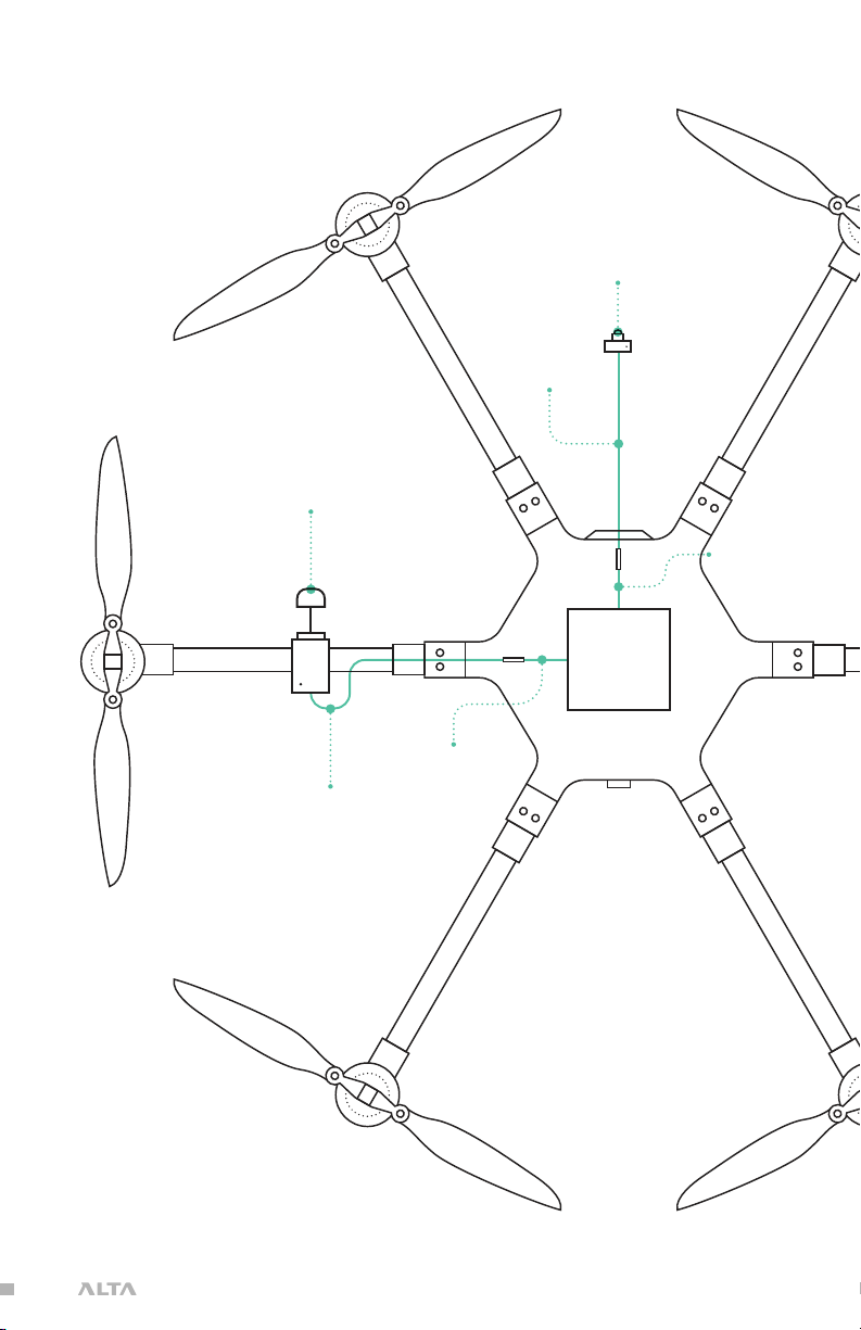
FPV EQUIPMENT
FPV Tx
(not included)
FPV Camera
(not included)
FPV Camera Cable
SYNAPSE
Flight
Controller
FPV Camera Lead
Pre-installed
FPV Tx Cable
Boscam/Skyzone or Fat Shark/ImmersionRC
FPV Tx Lead
Pre-installed
26| AIRCRAFT FLIGHT MANUAL
Page 27

ALTA MOBILE APP
The ALTA App is used to configure ALTA 6 parameters, update ALTA 6 firmware, and
to monitor ALTA 6 status during flight. To download the ALTA App, search for “Freefly
ALTA” in the App Store or on Google Play™.
Parameters may only be adjusted while ALTA 6 is on the ground and disarmed. In
addition, radio mapping parameters can only be adjusted when the Configuration
Jumper is removed. For more information on radio mapping, see the Radio Mapping
section of this manual.
The ALTA App will be actively maintained, and additional functionality may be added
over time. For information on individual app updates, refer to the App release notes.
NOTE
When making configuration changes with the ALTA App, wait
three seconds for the app to automatically save changes to
ALTA 6 before shutting off the app or the mobile device.
27| AIRCRAFT FLIGHT MANUAL
Page 28

ADDITIONAL REQUIRED COMPONENTS (NOT INCLUDED)
RADIO CONTROLLER
ALTA 6 supports a variety of radio controllers as outlined in the Flight Controller
Specifications. A minimum of five (5) channels are required, with four (4) used for
flight control, and the remaining one (1) used for mode selection.
However, a radio controller with at least 10 channels is highly recommended to
make use of Velocity and Climb Rate Clamps, Return-to-Home (RTH), Disarm Safety,
and Orbit Mode functions. It is recommended to use a radio controller with a three
way switch for the Mode, Home, and Orbit functions, a two or three way switch for
the disarm safety function, and a knob or slider input for both the Velocity and Climb
Rate Clamp functions.
FLIGHT BATTERY
ALTA 6 can accommodate a variety of Lithium Polymer (LiPo) flight battery packs.
Battery packs must be 6S, having a nominal voltage of 22.2 V. Only run ALTA 6 using
two packs at a time. Each pack must have a continuous discharge rating of 200
amps or greater, and a peak discharge rating of 400 amps or greater. For additional
information on expected flight durations, refer to the Performance Section of this
manual.
28| AIRCRAFT FLIGHT MANUAL
Page 29
SETTING UP ALTA 6
29| AIRCRAFT FLIGHT MANUAL
Page 30
UNFOLDING ALTA 6
ALTA 6 features swan-neck booms that fold into a compact size for
travel. They are secured in an open position for flight using overcenter latches.
TO UNFOLD ALTA 6
1. Remove ALTA 6 from case
2. Fold down all six boom retention clips
3. Open ALTA 6 booms. ALTA 6 can become unbalanced and tip
over while unfolding booms individually, so unfold opposite
boom pairs simultaneously to keep balance.
30| AIRCRAFT FLIGHT MANUAL
Page 31

4. Snap shut all six boom latches until they click and latch
5. Visually confirm all latches are seated properly
6. Remove prop protectors
31| AIRCRAFT FLIGHT MANUAL
Page 32

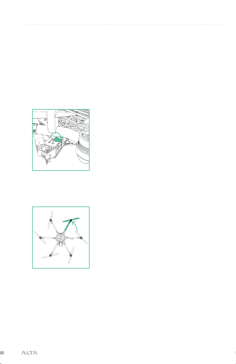
TO FOLD ALTA 6
1. Secure props with prop protectors
2. Unlatch all six booms
3. Close ALTA 6 booms in opposing pairs to keep balance
4. Fold up all six boom retention clips to secure booms
32| AIRCRAFT FLIGHT MANUAL
Page 33

RADIO INSTALLATION
RADIO CONTROLLER RECEIVER
ALTA 6 requires the installation of a radio control system. S.Bus, S.Bus2, DSM2,
DSMX, and PPM (including inverted PPM and Graupner) receiver types are
supported. Some of ALTA 6 emergency control modes (Return-to-Home and
Autoland) may vary depending on the type of radio. Refer to the Flight Controller
Modes section of this manual for additional detail.
Additionally, ALTA 6 supports radio receiver diversity using S.Bus, S.Bus2, DSM2 and
DSMX receivers. This means two receivers may be installed, and the SYNAPSE flight
controller will automatically use the receiver with the best signal quality. Using two
receivers requires the radio controller to be bound to both receivers.
Refer to the instructions provided with your radio controller to complete the binding
process. For Spektrum/JR radios, a receiver is required to bind the satellites to a
radio controller.
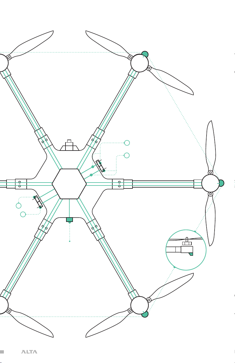
1. Locate the noted closeout panels used for receiver installation
(between booms 1 & 2 and 4 & 5). PPM and Graupner receivers
can only use the position between booms 1 & 2.
2. Remove side closeout panel with radio wires using a 1.5mm hex driver
33| AIRCRAFT FLIGHT MANUAL
Page 34

3. Identify required wire
PPM
4. Feed wire through grommet
5. Replace side closeout panel
DSM2/DSMXS.BUS/S.BUS2
6. Plug in receiver/satellite to wire per the radio
manufacturer’s installation instructions
34| AIRCRAFT FLIGHT MANUAL
Page 35

7. Attach receiver/satellite to exterior using the provided double sided tape
a. Futaba & PPM
b. Spektrum/JR
8. For Futaba receivers, feed antenna wires into antenna
tubes and zip tie to noted mounting location
9. Repeat 1-8 on opposite side for dual receivers (only
applies to Futaba and Spektrum/JR)
35| AIRCRAFT FLIGHT MANUAL
Page 36

RECOMMENDED RECEIVER PLACEMENT
FUTABA
Mount Futaba receivers 15mm from the wiring grommet for easy S.Bus wire
installation and removal (See Radio Controller Receiver step 7a).
SPEKTRUM/JR SATELLITES
Mount satellites so antennae are blocked by the airframe as little as possible. If
using two receivers, place them at a 90° angle to each other. (See Radio Controller
Receiver 7b)
VOLTAGE TELEMETRY
ALTA 6 supports battery voltage telemetry on Futaba radios using a receiver that
supports an external voltage sensor, such as the R7008SB. Installing the telemetry
wire is easiest when initially installing the receiver. To set up ALTA 6 with voltage
telemetry for Futaba radios:
1. Locate the radio receiver wire bundle behind the
closeout panel between booms 1 and 2.
2. Identify the voltage sense wire and connector in the bundle. It is the
small, 2-pin connector attached to a black and red wire pair.
NOTE
This wire is already connected to an in-line fuse.
Soldering a fuse into this wire is not required.
36| AIRCRAFT FLIGHT MANUAL
Page 37

3. Feed the voltage sense wires through the grommet on the closeout panel.
4. Connect the cable to the external voltage sense
port on the primary Futaba receiver.
37| AIRCRAFT FLIGHT MANUAL
Page 38

RADIO CHANNEL MAPPING
ALTA 6 can be used with a variety of radio controllers. Different radio controllers
can map functions to different channels, so properly mapping controller channels
to ALTA 6 functions is an important step before flying. Radio channel mapping is
performed using the ALTA App.
This section describes the steps required to complete radio channel mapping.
If you are uncertain about your radio channel mapping, obtain assistance from an
experienced pilot or from Freefly Customer Support.
CONFIGURATION JUMPER
A small jumper is used to prevent motor operation while configuring radio channel
mapping parameters. With the jumper in place, the motors may operate, but radio
channel mapping is prevented. With the jumper removed, radio channel mapping
may take place, but motor operation is prevented.
To remove or replace the Configuration Jumper:
1. Locate the closeout panel between booms 5 & 6 where the jumper is installed
2. Remove the closeout panel using a 1.5mm hex driver
38| AIRCRAFT FLIGHT MANUAL
Page 39

3. Remove or replace the jumper as needed
4. Reattach the closeout panel
MAPPING RADIO CHANNELS USING ALTA APP
Radio channel mapping is accomplished with the ALTA App. Prior to mapping
channels, ensure your radio controller and receivers are properly installed.
Refer to the Radio Installation section of this manual and your radio controller’s
documentation.
1. Remove the Configuration Jumper
WARNING
Always ensure the Configuration Jumper is removed prior to
adjusting radio settings to prevent unintentional motor starts.
2. Power ALTA 6 using a battery pack or by plugging in the included
USB-Futaba cable into an available port on a Futaba receiver
3. Open the ALTA App and connect to ALTA 6
4. Open Configurations > Radio
5. Open each ALTA 6 function and adjust the channel to the desired channel
number. Use the toggle in the App to invert the control orientation as needed.
6. Ensure proper radio channel mapping by moving the control
input on the radio controller and verifying the displayed
graph in the ALTA App responds as-expected
WARNING
Incorrect channel mapping can lead to immediate loss of control.
39| AIRCRAFT FLIGHT MANUAL
Page 40

ONCE CHANNELS ARE MAPPED
7. Remove the battery or USB-Futaba cable from ALTA 6
8. Replace the Configuration Jumper
FUNCTION DESCRIPTIONS
The following functions can be mapped to radio controller channels. These are found
in the Radio section of the Configurations menu in the ALTA App. Each function
is also represented by a chart that responds to control input allowing for quick
verification of mapping settings.
CONTROLLER
Use this to select the appropriate receiver. The following guide is compiled for
convenience. For complete specifications and which mode will work with your
receiver, refer to your radio controller or receiver manuals.
» DSM2/DSMX are typically used by Spektrum and some JR controllers.
» SBUS is typically used by Futaba controllers.
» PPM is a generic standard used by many controllers and receivers.
» PPM Invert is the same as PPM except channel inputs are reversed.
» PPM Graupner interprets Graupner radio PPM inputs.
PITCH/ROLL/YAW/THROTTLE
The Pitch, Roll, Yaw and Throttle controls are the basic flight controls and are
mapped to the two radio controller sticks.
MODE
The required Mode Switch selects between the three different flight modes: Manual,
Height, and Position. A three-position switch is recommended to select the three
different modes. However, a two-position switch may be used, but will only allow for
selecting between Manual Mode and (depending on radio controller mixes) either
Position Mode or Height Mode
HOME SWITCH
The optional Home Switch selects between the different Return-to-Home (RTH)
functions. A three-position switch is required for the Home Switch functions to
select between the Set New Home Position, RTH Off, and initiate RTH functions.
VELOCITY AND CLIMB RATE CLAMP
Velocity and Climb Rate Clamps set the maximum ground speed or vertical speed
available in Height Mode and Position Mode. The clamps can be adjusted mid-flight.
An analog dial or slider is recommended for the Velocity and Climb Rate Clamp
Functions.
40| AIRCRAFT FLIGHT MANUAL
Page 41

DISARM SAFETY
The Disarm Safety Switch aids in preventing accidental motor disarming while the
ALTA is in flight and in manual mode. It may be mapped to either a two-position
or three-position switch. To set up the Disarm Safety Switch, refer to the Mapping
Channels section of the ALTA Aircraft Flight Manual.
ORBIT MODE
The optional Orbit Switch selects between the different Orbit Mode functions. A
three position switch is required to select between the Set Orbit Center, Orbit Off,
and Orbit On functions.
ALL FUNCTIONS
The meaning of the direction or position of the indicator is described in the following
table for all mappable parameters. The top and right positions on the radio mapping
indicators represent 2000s, and the bottom and left positions represent 1000s,
and the middle position represents 1500s.
FUNCTION
Pitch
Roll
Yaw
Throttle
Mode
Home
Velocity Clamp
Climb Rate
Clamp
IN-APP
INDICATOR
POSITION
INDICATES
Top Nose Up
Bottom Nose Down
Left Roll Left
Right Roll Right
Left Nose Left
Right Nose Right
Top High Throttle
Bottom Low Throttle
Top Position
Middle Height
Bottom Manual
Top Set New Home Position
Middle RTH Off
Bottom Initiate RTH
Top Fast
Bottom Slow
Top Fast
Bottom Slow
41| AIRCRAFT FLIGHT MANUAL
Page 42

Disarm Safety
Orbit
Top On - Disarming Not Possible
Middle &
Bottom
Off - Disarming Possible
Top Orbit On
Middle Orbit Off
Bottom Set Orbit Center Point
42| AIRCRAFT FLIGHT MANUAL
Page 43

TYPICAL CHANNEL MAPPINGS
The following radio channel mapping configurations are recommendations only and
can be set in the ALTA App. Depending on exact radio models, these may help as
an initial configuration. However, it is up to the pilot setting up ALTA 6 for flight to
determine if these settings are appropriate.
FUTABA 14SG/8FG
FUNCTION CHANNEL NUMBER DIRECTION
Pitch 2 Normal
Roll 1 Normal
Yaw 4 Normal
Throttle 3 Reverse
Mode Switch 5 Normal
Home Switch 6 Reverse
Disarm Safety 9 Reverse
Velocity Clamp 8 Reverse
Climb Rate Clamp 7 Reverse
Orbit Switch 10 Normal
SPEKTRUM DX18
FUNCTION CHANNEL NUMBER DIRECTION
Pitch 3 Reverse
Roll 2 Reverse
Yaw 4 Reverse
Throttle 1 Normal
Mode Switch 6 Reverse
Home Switch 7 Normal
Disarm Safety 8 Normal
Velocity Clamp 10 Normal
Climb Rate Clamp 9 Normal
Orbit Switch 5 Normal
43| AIRCRAFT FLIGHT MANUAL
Page 44

CONFIGURING FOR MŌVI
A MōVI can be attached to either the top or bottom of ALTA 6 via the Freefly Toad In
The Hole (TITH) quick release.
ALTA 6 comes pre-configured for GroundView mounting a MōVI.
GROUNDVIEW
1. Prepare your MōVI for GroundView flight (see MōVI manual)
a. Attach landing gear
b. Install TITH receiver on MōVI
2. Connect MōVI to bottom Toad
SKYVIEW
CAUTION
Top mounting is not supported by the MōVI M10 without the keyed
pan tube upgrade kit. If you are unsure whether your M10 has the
upgrade kit, contact Freefly Customer Support for additional info.
1. Prepare your MōVI for SkyView flight
a. Remove landing gear (see MōVI manual)
b. Install TITH receiver on MōVI (see MōVI manual)
44| AIRCRAFT FLIGHT MANUAL
Page 45

2. Connect and secure the supplied inverted landing gear to the bottom Toad
3. Remove the four flat-head M3×6 bolts that secure the top handle
4. Attach the supplied Toad to the top plate using the four M3×8 bolts provided
5. Connect MōVI to the top Toad
45| AIRCRAFT FLIGHT MANUAL
Page 46

ISOLATOR CARTRIDGES
Different Isolator Cartridges can be used to fine tune vibration damping
performance for different payload weights or ambient temperatures. Three isolation
cartridge styles are provided with ALTA 6. The cartridges have o-rings colored red
for light payloads or cold ambient temperature, teal for medium payloads or typical
ambient temperature, and black for heavy payloads or hot ambient temperature.
Flight testing may be required to determine the optimal isolator for a given setup.
To install, place the cartridges between the top chassis plate and the battery plate.
Ensure they are engaged in the track features and are parallel with the chassis and
battery plate. Push inwards fully until they click, indicating the cartridges are locked
in place. Pull outwards on the cartridge to ensure it is locked in place.
CAUTION
Always ensure isolator cartridges are locked in place
before flying ALTA 6. Isolator cartridges that are not
locked can cause the payload to loosen and change
ALTA 6’s fundamental flying characteristics.
To remove, pinch the cartridge latch to unlock it from the battery and chassis plate,
and slide it outwards to disengage. Simultaneously pull the battery and chassis plate
apart while pulling the cartridge outward.
46| AIRCRAFT FLIGHT MANUAL
Page 47

BATTERY INSTALLATION
Batteries may be installed on either the top or bottom of an ALTA 6 and are always
mounted opposite of the payload location. In both locations, battery packs are
secured with silicone straps tensioned across the packs. The straps are secured
using studs located on either side of the packs.
WARNING
Always secure battery packs with both battery retention straps.
CAUTION
Ensure both battery packs are at a similar state of charge (a
full pack voltage difference less than 0.5V) prior to connecting
them to ALTA 6. Plugging in two dissimilarly charged packs
could cause one pack to rapidly discharge into the other
and damage the batteries or cause a battery fire.
CAUTION
Only use packs that are identical in their capacity and at a similar
condition. Using a pack with another that is larger, or has many
more charge/discharge cycles, can damage the battery packs.
CAUTION
Always refer to and follow the battery manufacturer’s instructions,
recommendations and guidelines for battery handling.
CAUTION
When plugging in battery packs, ensure the polarity is
correct. Positive is indicated by a red power lead, and
negative/ground is indicated by a black power lead.
Reversing polarity will damage ALTA 6’s electronics.
47| AIRCRAFT FLIGHT MANUAL
Page 48

GROUNDVIEW
1. Place battery retention strap studs at the appropriate
height to hold the battery packs firmly in position
2. Adjust battery stops to fit battery packs
3. Attach the single-hole end of the battery retention straps to the studs
48| AIRCRAFT FLIGHT MANUAL
Page 49

4. Place battery packs on the battery tray
CAUTION
Do not install batteries directly on the lower battery tray
if a Toad adapter is also installed. Either remove the
Toad adapter or use the Quick Release Battery Tray.
5. Tension and secure battery retention straps
49| AIRCRAFT FLIGHT MANUAL
Page 50

SKYVIEW
CAUTION
Always completely secure the inverted landing gear by closing
the TITH quick release lever. Inverted landing gear that are not
completely attached can rotate and unplug battery leads.
1. Pinch the battery tray handles and slide to remove it from landing gear
2. Attach the single-hole ends of the battery retention straps to the studs on the
battery tray
3. Place battery packs onto battery tray
50| AIRCRAFT FLIGHT MANUAL
Page 51

4. Tension and secure battery retention straps
5. Slide tray with battery packs back into landing gear until the tray latches in
place
6. Ensure tray and battery packs are secure
51| AIRCRAFT FLIGHT MANUAL
Page 52

COMPASS CALIBRATION
ALTA 6 features a highly sensitive 3-axis magnetometer that measures the earth’s
magnetic field to infer heading. Occasionally, the compass will require calibration,
especially when traveling between different geographic locations.
For best results, it is recommended to perform manual compass calibrations away
from ferrous objects, buildings and vehicles. In addition, concrete can contain steel
rebar which may influence compass calibrations.
WARNING
Verify ALTA 6 is disarmed prior to performing a compass
calibration. To ensure ALTA 6 does not arm, remove the
Configuration Jumper, set the mode switch to Height or
Position, or set the home switch to Set New Home Position.
NOTE
Ensure a microSD card is installed in the GPS/compass
module prior to performing compass calibration.
NOTE
Perform calibration without a payload attached. It is
recommended to use two people to perform the compass
calibration as it requires handling and rotating ALTA 6.
52| AIRCRAFT FLIGHT MANUAL
Page 53

TO PERFORM A COMPASS CALIBRATION:
PITCH -180º FACE EAST (YAW +90º) ROLL+180º
PITCH +360º PITCH +180º
Boom 1 Boom 1
ROLL+360º
Boom 1
Boom 1
Boom 1
ROLL+360º
Boom 1
Boom 1
PITCH +360º PITCH +180º
Boom 1
Boom 1
ROLL+360º
Boom 1
Boom 1
ROLL+360º
1. Secure a battery onto ALTA 6
2. Plug in the battery
3. Open the ALTA App
4. Select Configurations > More > Compass
5. Under Calibration, select Start Manual
6. Perform the following steps:
1. Face North, Pitch +180º
Boom 1
3. Pitch +180º
Boom 1
Boom 1
5. Roll +180º
2. Pitch -360º
4. Face East (Yaw 90º)
6. Roll -360º
Boom 1
Boom 1
Boom 1
53| AIRCRAFT FLIGHT MANUAL
Page 54

AUTOMATIC COMPASS CALIBRATION
Automatic Compass Calibration will use compass readings over time to resolve an
accurate compass calibration. Manual calibration is recommended when moving to
a new location and an accurate compass calibration is needed immediately for using
Position Mode.
In the ALTA App, select Configurations > More > Compass. Change the Auto
Calibration setting to On.
54| AIRCRAFT FLIGHT MANUAL
Page 55

PROPELLERS
The folding propellers include two balanced carbon fiber propeller blades attached
to propeller hubs, which are themselves secured to the motors. The propellers
installed on booms 1, 3, and 5 spin clockwise when viewed from above ALTA 6, and
the propellers installed on booms 2, 4, and 6 spin counterclockwise when viewed
from above.
For information on propeller installation and maintenance, refer to the Maintenance
section of this manual.
CAUTION
Only use propellers supplied by Freefly on ALTA 6. Use of third-party
propellers can cause motor instability, overheating, and failure.
55| AIRCRAFT FLIGHT MANUAL
Page 56

CHECKING PROPELLER BOLT TIGHTNESS
Over time, the bolts that hold the propeller blades to the propeller hub can loosen
due to vibration. To check propeller bolt tightness, twist the propeller about its
length. If there is free play, the propeller bolt is too loose. Use the provided 2.5mm
hex driver and wrench to tighten the bolt and nut that secure the propeller blade just
enough to remove the play.
CAUTION
Do not overtighten, or the propeller may fail to unfold completely
during motor start up, leading to excessive vibration.
56| AIRCRAFT FLIGHT MANUAL
Page 57

FIRST PERSON VIEW (FPV)
ALTA 6 and SYNAPSE can power a variety of first person view (FPV) cameras and
transmitters, as well as add informational on-screen display (OSD) elements to
aid in FPV flying. Using an FPV ground station display can be a useful method of
monitoring status, performance, and flight parameters of the ALTA 6 during flight.
Three FPV transmitter cables are included. Each supplied cable has one side with
a connector that mates with a cable located in the closeout panel between booms
1 & 2. The other end of each supplied cable has specialty connector(s) to run
Immersion RC, Fatshark, BOSCAM, or BOSCAM compact FPV transmitters. For
cable identification, refer to the FPV Transmitter installation instructions.
A single camera cable is provided and is configured to run a Ready Made RC camera
(model RMRC-700XVN recommended). This cable mates with a pre-installed cable
located behind the closeout panel between booms 1 & 6.
Camera and transmitter cables follow this wiring scheme:
CABLE COLOR FUNCTION
Red +12 VDC
Black Ground
Yellow Video signal
WARNING
It is the responsibility of the pilot to see and avoid other aircraft,
people, or obstacles. Always maintain direct line of sight with
ALTA 6 during flight, use visual observers as operations require,
and follow local regulations regarding see-and-avoid requirements.
CAUTION
Do not short the pins of the FPV transmitter connector located
on the pre-installed FPV transmitter lead in the ALTA 6. Doing so
could damage the on-screen display circuit. If using a multimeter
to check the pins, first connect one of the provided transmitter
cables, then take voltage readings from the transmitter cable.
57| AIRCRAFT FLIGHT MANUAL
Page 58

FPV SYSTEM INSTALLATION
CAMERA
1. Mount FPV camera on the FPV mount on the front
underside of ALTA 6 or other preferred location.
2. Locate the FPV camera cable included in the ALTA 6 package.
3. Remove the front closeout panel with a 1.5 mm hex driver.
4. Pass the FPV cable through the grommet, and connect to the mating FPV
camera lead inside ALTA 6. Connect the other end directly to the camera.
58| AIRCRAFT FLIGHT MANUAL
Page 59

5. Replace front closeout panel.
TRANSMITTER
1. Mount FPV transmitter on the provided carbon fiber accessory mount plate.
2. Attach accessory mount to boom 5 with M3x6 flathead bolts.
3. Locate the appropriate FPV transmitter cable. The following cables are included:
a. ImmersionRC/Fat Shark (cable with two connectors)
b. BOSCAM/SkyZone (cable with one large connector)
a.
b.
c. Compact BOSCAM (cable with one small connector)
c.
59| AIRCRAFT FLIGHT MANUAL
Page 60

4. Remove the side closeout panel with the FPV transmitter lead
between booms 5 & 6 using the 1.5mm hex driver.
5. Pass transmitter cable through the underside of the
hinge, and connect to the FPV transmitter lead.
6. Replace side closeout panel.
7. Zip tie the FPV transmitter lead to the boom cable bundle for strain relief.
60| AIRCRAFT FLIGHT MANUAL
Page 61

FPV ON SCREEN DISPLAY SETUP
A number of properties and components can be adjusted or added to the FPV On
Screen Display (OSD) using the ALTA App.
PROPERTIES
NAME OPTIONS DESCRIPTION
Video Mode PAL / NTSC
Units
Horizontal
Offset
Vertical Offset 0, 8, 16, 24, 30 Centers the OSD components vertically
Borders 0, 1, 2, 3
TEXT COMPONENTS
The following components are displayed as text items, and can be configured to
display as big or small letters, or no letters effectively turning off the display.
NAME DESCRIPTION
Height
Vario
Heading
Distance
Ground Speed
Battery Displays the voltage of the flight battery packs
Time Displays the time of the flight in minutes and seconds
GPS Displays the number of GPS satellites in view
GPS Accuracy
Lat/Long
Metric /
Imperial
0, 15, 30, 45, 60 Centers the OSD components horizontally
Indicates to the SYNAPSE the
FPV video camera format
Changes the displayed units
Adds gaps between OSD components
and the edges of the display, measured
in character widths and heights
Displays the height of ALTA 6 from its
starting point in meters or feet
Displays the vertical speed of ALTA 6 in
meters per second or feet per minute
Displays the magnetic heading of
ALTA 6 and is measured in degrees
Displays the horizontal distance along the
ground ALTA 6 is from the initialization
position in meters or feet
Displays the ground speed of ALTA 6
in meters per second or knots
Displays the horizontal accuracy of the
GPS signal in meters or feet
Displays the GPS derived latitude and
longitude coordinates of ALTA 6
61| AIRCRAFT FLIGHT MANUAL
Page 62

ARTIFICIAL HORIZON COMPONENTS
The artificial horizon displays pitch and roll information in the center of the FPV
display in the form of a horizon line and accompanying elements.
NAME OPTIONS DESCRIPTION
No Turns off all artificial horizon components
Artificial
Horizon
Basic
Ladder
Adds a horizon line that moves up and down as
ALTA 6 changes pitch and rolls as ALTA 6 rolls
Adds pitch marks at intervals defined
by the Pitch Interval setting
Adds small dash marks on the left
Basic
and right side of the artificial horizon
that indicate changes in roll
Roll Marker
Horizon Adds marks to include a full horizon line
Adds small marks on either side of
Ladder
the artificial horizon ladder that roll
with ALTA 6 roll movements
Pitch and
Roll Scaling
Pitch and
Intervals
10, 20, 30, 40
10, 20, 30, 40
Allows for scaling of the artificial
horizon markings to compensate for
FPV cameras of different field views
Sets the number of degrees
between pitch markings when the
artificial horizon ladder is used
OTHER COMPONENTS
The following components can be turned on or off. These components do not have
adjustable settings.
NAME DESCRIPTION
Compass Arrow Displays an arrow that points in the direction of north
Home Arrow
Displays an arrow that points in the
direction of the initialization point
Displays a bar on the right of the screen that scales
Vario Bar
with vertical speed. The bar will increase in length
up to indicate a climb, or down to indicate a descent
Displays a bar on the left of the screen that scales
with the forward/rearward velocity component
Forward Velocity
The bar will extend up to indicate forward velocity,
or down to indicate a rearward velocity
62| AIRCRAFT FLIGHT MANUAL
Page 63

Sideslip
Displays a bar on the bottom of the screen that
scales with the side-to-side velocity component
The bar will extend left to indicate leftward
velocity, or right to indicate rightward velocity
63| AIRCRAFT FLIGHT MANUAL
Page 64

TUNING ALTA 6
ALTA 6 comes pre-tuned for a wide variety of payloads and flying conditions.
Generally, additional tuning is not required to fly ALTA 6, and additional tuning will
only need to take place if more customization of control feel is desired. Default
tuning values are included in Appendix A, Default Tuning Values.
Parameters fall into three categories - Attitude, Height, and Position. Typically,
tuning should take place in that order, ensuring Attitude parameters are set first,
then moving to Height parameters, and finally Position parameters.
Before tuning, the user should read and become familiar with all flight controller
modes listed in the Operating ALTA section of this manual. Tuning should take
place as an iterative process by making only small changes, test flying the changes,
observing the new flight behaviors, and repeating. Only tune a single parameter at a
time during this process for best results.
To tune ALTA 6, open the ALTA App and select Configurations > Aircraft Dynamics.
WARNING
Tuning can change the fundamental flying characteristics of ALTA 6.
It is possible for ALTA 6 to become unstable or even uncontrollable
if values are set too high or too low. Only change tuning parameters
in small increments and with caution. Always test new tuning
configurations in open areas away from people or obstacles.
NOTE
The ALTA App only allows tuning while ALTA 6 is on the ground.
NOTE
When making configuration changes with the ALTA App, wait three
seconds before closing the app for changes to be saved automatically.
64| AIRCRAFT FLIGHT MANUAL
Page 65

ATTITUDE TUNING
Attitude tuning adjusts how ALTA 6 responds to control inputs and disturbances.
Attitude directly controls responsiveness and changes ALTA 6’s fundamental flying
behaviors. Attitude must be tuned acceptably before tuning height or position
parameters.
When tuning attitude, the primary parameter to change is Stiffness followed by
Strength.
STIFFNESS
Stiffness is adjusted for pitch and roll simultaneously, and yaw independently. It
changes how stable ALTA 6 is in these axes and is the primary variable to adjust
when tuning. When tuning Stiffness first, or making large stiffness changes, Hold
Strength should be set to a low, non-zero value.
Higher Stiffness values give more responsive control. Values that are too high can
cause instability or oscillation.
WARNING
Excessively high stiffness values can cause ALTA 6 to become
unstable and difficult or even impossible to control.
Lower Stiffness values give less responsive control. Values that
are too low can cause a vague or disconnected control response.
HOLD STRENGTH
Hold Strength controls how much ALTA 6 will try to maintain a pitch/roll
angle command, or a yaw heading command. It is adjusted for pitch and roll
simultaneously, and yaw independently. A higher Hold Strength setting will give a
faster control response and a more responsive feel. However, values that are too
high can cause ALTA 6 to overshoot pitch or roll commands, or even cause instability.
WARNING
Excessively high strength values case cause ALTA 6 to become
unstable and difficult or even impossible to control.
Typically, this setting will not need to be changed from
the default value, and only then in small increments.
65| AIRCRAFT FLIGHT MANUAL
Page 66

HEIGHT TUNING
Tuning height parameters will adjust the control feel of ALTA 6’s height control while
in Height and Position modes (for additional information on flight modes, see the
Flight Controller Modes section of this manual). Tune height parameters only after
satisfactorily tuning attitude parameters.
Similar to attitude tuning, stiffness is the primary tuning parameter.
If switching to Height Mode causes ALTA 6 to fly in an unstable manner, switch back
to Manual Mode, land, and try reducing the values of height tuning gains if they are
very high or increasing them if they are very low.
VERTICAL STIFFNESS
Vertical Stiffness Gain modifies the vertical stability of the ALTA 6 in Height mode.
Decrease this value if ALTA 6 experiences vertical oscillation or vibration. Increase
this value if ALTA 6 is sluggish while accelerating to a desired climb or descent rate
in Height mode.
HOLD STRENGTH
Hold Strength Gain tunes how much ALTA 6 will attempt to stay on a desired
altitude in Height Hold mode only. A higher value will result in height being held
more precisely. A value too high can cause ALTA 6 to overreact to winds, gusts, or
turbulent air.
CLIMB RATE STRENGTH
Climb Rate Strength adjusts how much ALTA 6 will attempt to maintain a desired
climb rate. Higher values will result in a more direct feel between pilot climb or
descent commands and ALTA 6 flying behavior. However, values that are too high
may cause instability.
POSITION TUNING
Tuning position parameters will adjust how well ALTA 6 maintains a desired ground
speed or a position over the ground. Similar to attitude and height tuning, the
primary value to adjust is stiffness.
HORIZONTAL STIFFNESS
This changes the horizontal stability of ALTA 6. Higher values increase ALTA 6’s
resistance to wind gusts or turbulence from moving ALTA 6 off its target position.
Values that are too high can cause instability of ALTA 6.
66| AIRCRAFT FLIGHT MANUAL
Page 67

HOLD STRENGTH
This adjusts how much ALTA 6 will attempt to maintain its place over a target
position. A higher value will result in position being held more precisely. If too high,
positional instability can result, causing ALTA 6 to fly past a target position.
KINEMATIC MODE
When selected, Kinematic mode affects the control feel of the ALTA 6 in Position
Mode only. This control algorithm uses inertial and friction models to control the
ALTA 6 response to stick inputs. Kinematic Mode is intended to make the ALTA 6
flight characteristics feel more like Manual Mode control while still benefiting the
user with GPS assist.
KINEMATIC MASS
This is the primary tuning parameter to adjust the feel of the ALTA 6 when Kinematic
Mode is enabled. Tuning Kinematic Mass to higher values makes the ALTA behave
as an object with more inertia; it will glide to a stop over a further distance when
decelerating or take longer to gather speed when starting a pass. Tuning Kinematic
Mass to lower values will make the ALTA 6 snappier and accelerate at higher rates
when starting or stopping flight passes.
67| AIRCRAFT FLIGHT MANUAL
Page 68

ALTA 6 FLIGHT PARAMETERS
Flight Parameters are different from tuning parameters in that the flight
characteristics of ALTA 6 will not change with their modification. However, they can
be used to select neutral points using trim, or to set maximum or minimum values.
ATTITUDE
PITCH AND ROLL TRIM
Use Pitch and Roll trim settings to correct for tendencies of the ALTA 6 to pitch or
roll with a neutral control input.
Use the in-app pitch and roll trim settings instead of radio controller trim features
as large radio controller trims could prevent position hold from engaging at neutral
stick positions.
MAXIMUM PITCH/ROLL ANGLE
This sets the maximum angle ALTA 6 will be allowed to fly in any flight modes and in
all flight conditions.
MAXIMUM YAW RATE
This is the maximum rate ALTA 6 will yaw (pan) when at full stick deflection.
HEIGHT
HOVER THROTTLE
Hover Throttle is a parameter that adjusts ALTA 6’s thrust at center throttle stick and
ensures ALTA 6 does not climb or descend at the center stick position while flying in
Manual Mode. A Hover Throttle setting that is too high or too low can cause ALTA 6
to climb or descend when switching between Manual and Height Mode.
NOTE
Hover Throttle will need to be adjusted when
changing the overall weight of the system or when
moving between very different elevations.
Increase Hover Throttle if the throttle stick must be set above center in order to
hover in Manual Mode, and decrease Hover Throttle if the throttle stick must be set
below center in order to hover in Manual Mode.
68| AIRCRAFT FLIGHT MANUAL
Page 69

Alternatively, if ALTA 6 climbs when switching from Manual to Height mode, increase
hover throttle since a climb indicates a stick position that is higher than neutral in
Manual Mode. If ALTA 6 descends, decrease hover throttle since a descent indicates
a stick position that is lower than neutral in Manual mode.
NOTE
The ALTA App does not allow real-time hover throttle adjustments
while ALTA 6 is flying. Therefore, adjust the hover throttle while
the ALTA 6 is on the ground, and test fly to assess the result.
MAXIMUM CLIMB RATE
This sets the maximum speed ALTA 6 will climb at full throttle stick deflection in
Height Mode or Position Mode.
If Climb Rate Clamp is mapped to a radio controller channel, the parameter will
adjust the fastest climb speed available to the Climb Rate Clamp feature.
POSITION
MAXIMUM G
This sets the total maximum acceleration, in G’s, that the controller will place on the
airframe. It is recommended to use lower G settings with heavier payloads.
This setting has no effect in Manual Mode.
MAXIMUM GPS ANGLE
This sets the maximum pitch and roll angle the ALTA 6 may fly under Position mode.
This will not override the Attitude Maximum Pitch/Roll Angle. Instead, ALTA 6 will
follow the lower of these two limits when flying in Position Mode.
MAXIMUM GPS SPEED
Max GPS Speed sets the maximum ground speed ALTA 6 will fly at full stick
deflection in Position Mode.
If Velocity Clamp is mapped to an RC transmitter channel, the parameter will adjust
the fastest ground speed available to the Velocity Clamp feature.
69| AIRCRAFT FLIGHT MANUAL
Page 70

SAFETY
ALARM VOLTAGE
This adjusts the per-cell voltage warning level. Below this value, the Status Light
will illuminate red and Orientation Lights will flash, indicating the flight packs are at
a low state of charge.
LAND VOLTAGE
This adjusts the per-cell voltage limit below which ALTA 6 will begin to Autoland
while flying in Height or Position Mode. Below this value, the Status Light and
Orientation Lights will flash to convey the flight packs are at or below the land
voltage. When flying in Manual Mode, the pilot will be alerted by the alarm
indication, but Autoland will not be initiated.
SAFE HEIGHT
This adjusts the minimum height above the starting point at which ALTA 6 will fly
during a Return-to-Home.
AUTOLAND DESCENT RATE
This adjusts the descent rate of the ALTA 6 during Autoland in meters per second.
This value is applied to the Autoland descent profile for the final 15 meters above
the ground until landing. The Autoland descent profile is hard-coded and adjusts
automatically as a function of height when the ALTA 6 is above 15 meters.
RTH SPEED
This adjusts the ground speed at which ALTA 6 will fly during a Return-to-Home.
SIGNAL LOS ACTION
This parameter determines the flight mode ALTA 6 will enter if it detects a Loss-ofSignal (LOS). Selecting ‘LAND’ will cause ALTA 6 to Autoland in place when the LOS
is detected. Selecting ‘RTH’ will cause ALTA 6 to Return-to-Home and then Autoland
when the LOS is detected.
NOTE
Signal LOS Action functionality may be limited when using receiver
types other than S.Bus/S.Bus2 or DSM2/DSMX. Refer to the Flight
Controller Modes section of this manual for additional information.
70| AIRCRAFT FLIGHT MANUAL
Page 71

MOTION BOOTING
Motion Booting can be used when powering up ALTA 6 from a moving platform such
as a boat. Motion Booting bypasses sensor checks during boot, so it should remain
off whenever possible.
CEILING
This adjusts the highest altitude the ALTA 6 is allowed to climb from its starting point
while in Height or Position modes. If the maximum ceiling is exceeded in Manual
mode, the Status Light will illuminate white.
NOTE
The maximum ceiling parameter can be turned off in
the ALTA App, and the maximum height of the ALTA
6 will be unconstrained in all flight modes.
RANGE
Range sets the maximum distance ALTA 6 may fly away from the home point while
in Position mode. If the range is exceeded in Manual mode, the Status Light will
illuminate white.
NOTE
The maximum range parameter can be turned off in
the ALTA App, and the maximum flight distance of the
ALTA 6 will be unconstrained in all flight modes.
71| AIRCRAFT FLIGHT MANUAL
Page 72

RESETTING ALTA 6 WIFI PASSWORD
How to Reset WiFi Password On Your Freefly Device
If you forget your WiFi password and are locked out, you can reset it with the steps below.
It will also reset your SSID (if you have renamed your device).
1. Power on.
2. Within 3 seconds of powering on,
2. ALTA 6 2. ALTA 8
press and hold the reset button* for
10 seconds.
3. Power cycle.
ALTA
*Reset button is located on the front of the GPS
unit. On ALTA 6, the GPS unit is located on Boom #2.
On ALTA 8, the GPS unit is located on Boom #7.
MōVI M10/M15 - WiFi Edition
1. Power on.
2.
2. Within 3 seconds of powering on,
press and hold the reset button* for
10 seconds.
3. Power cycle.
*Reset button (orange) is located on the front face
of the GCU enclosure.
MōVI WiFi Adapter
2.
1. Press and hold the reset button.
2. Power on and and keep the reset
button held for 10 seconds.
3. Power cycle.
MIMIC Beta - WiFi Edition
1. Power on and wait until boot is complete.
2. Quickly press the Pan Freeze Button 8 times.
3. Power cycle
2.
72| AIRCRAFT FLIGHT MANUAL
Page 73

OPERATING ALTA 6
73| AIRCRAFT FLIGHT MANUAL
Page 74

FLIGHT CONTROLLER MODES
OPERATING ALTA 6
ALTA 6 has three primary flight control modes which are selected using the Mode
Switch: Manual Mode, Height Mode, and Position Mode. Position Mode includes two
control styles that can be selected in the ALTA App per user preference (Classic and
Kinematic). ALTA 6 has an assistive Orbit Mode which is available when Position
Mode is active. ALTA 6 also has two emergency control modes, Return-To-Home
and Autoland, which are available only during certain situations. For additional
information, refer to the sub-section associated with each emergency control mode.
WARNING
Height Mode and Position Mode are assistive only and
are not a replacement for pilot skill and ability. Pilots
should be proficient in Manual Mode flight in order
to react to emergency situations as required.
CAUTION
Always center the control input sticks on the radio
controller when switching between control modes to
prevent unexpected movement of the ALTA 6.
MANUAL MODE
In Manual Mode, ALTA 6 will only stabilize its attitude. At neutral control input
(middle pitch and roll stick position), ALTA 6 will attempt to remain level. Throttle
control is direct.
74| AIRCRAFT FLIGHT MANUAL
Page 75

HEIGHT MODE
Height Mode changes the throttle stick behavior to command climb and descent
rates. The higher the throttle stick position, the faster ALTA 6 will climb. Conversely,
the lower the throttle stick position, the faster ALTA 6 will descend.
When the throttle stick is centered, ALTA 6 will enter Height Hold. In Height Hold,
ALTA 6 will maintain a target altitude and try to correct for drift. If a disturbance
moves ALTA 6 away from this target altitude, ALTA 6 will climb or descend to return
to the target altitude.
WARNING
Height Mode is assistive only and is not a replacement for pilot
skill and ability. Pilots should be proficient in Manual Mode
flight in order to react to emergency situations as required.
POSITION MODE
Position Mode changes the pitch/roll stick behavior to command ground speeds.
Pitch and roll stick deflection will command fore/aft and left/right ground speeds
respectively. Controlling altitude in Position Mode is the same as in Height Mode.
With pitch and roll controls centered, ALTA 6 will enter Position Hold. In Position
Hold, ALTA 6 will maintain its position over a given point on the ground and correct
for disturbances.
Position Mode requires a strong GPS signal and communication with a minimum of 6
satellites. If a weak signal is present, ALTA 6 will not enter Position Mode. If the GPS
signal degrades while in Position Mode, ALTA 6 will automatically revert to Manual
Mode.
Within Position Mode, the user can select between two control styles. The Classic
controls use the Horizontal Stiffness and Hold Strength parameters to control
translational position over the ground. Kinematic Mode uses inertial and friction
models to control the ALTA 6 response to stick inputs.
WARNING
Position Mode is assistive only and is not a replacement for
pilot skill and ability. Pilots should be proficient in Manual Mode
flight in order to react to emergency situations as required.
75| AIRCRAFT FLIGHT MANUAL
Page 76

WARNING
Flight using Position Mode in areas of degraded GPS signal,
such as near buildings or under dense tree cover, is not
recommended. The automatic reversion to Manual Mode
can cause unexpected, abrupt changes in flight behavior.
WARNING
Flight using Position Mode with Compass enabled in areas near
large ferrous objects or high magnetic flux is not recommended.
Incorrect compass readings can result in loss of control.
Compass assist can be disabled in the ALTA App if desired.
ORBIT MODE
Orbit Mode allows the pilot to perform circular orbits of a desired radius around
a manually-set center point. Position Mode must first be active in order to enter
Orbit Mode. When activated, Orbit Mode constrains the radius and automatically
yaws ALTA 6 to point towards the center point as the pilot uses roll left or roll right
commands to traverse the flight path. The pilot maintains throttle control in order
to ascend or descend as desired. The radius of the circular orbit can be adjusted
real-time using pitch forward or pitch backward commands.
RETURN-TO-HOME
Return-to-Home Mode will command ALTA 6 to fly back to the starting point of the
flight or the last defined Home Point. When ALTA 6 first acquires a GPS position, it
sets this as the Home Point of the flight. The Home Switch on your radio controller
can be used to set a new Home Point within 20 meters of the initialization point. See
the Radio Channel Mapping section in this manual for more information on setting
up the Home Switch.
RTH can be initiated automatically with an LOS event if it is selected as the Signal
Loss Action in the ALTA App. RTH can also be initiated manually while flying in
Position Mode and setting the Home Switch to RTH.
76| AIRCRAFT FLIGHT MANUAL
Page 77

NOTE
Return To Home
Full functionality of the SYNAPSE LOS features is only available
on an S.Bus/S.Bus2 or DSM2/DSMX receiver. PPM receivers must
be programmed with failsafe actions manually before flight.
When initiated manually using the Home Switch, ALTA 6 will fly back to the Home
Point, and the pilot will maintain control of ALTA 6’s altitude the entire time. ALTA 6
will hover above the home point and wait for further commands. The pilot can cancel
the RTH procedure by commanding a pitch or roll command or by retuning the Home
Switch to the middle position. The Mode Switch must first be in Position Mode to
activate RTH manually.
During an LOS event, RTH followed by Autoland will be initiated automatically if
‘RTH’ is selected as Signal Loss Action in the ALTA App and an S.Bus/S.Bus2 or
DSM2/DSMX radio system is in use. ALTA 6 will first check its current altitude
against Safe Height. If ALTA 6 is below the Safe Height, it will climb to Safe Height.
If ALTA 6 is above Safe Height, it will remain at its current altitude. Next, ALTA 6 will
fly back to the home position at the RTH Speed set in the ALTA 6 App. Finally, upon
reaching the home position, ALTA 6 will begin Autoland.
SAFE HEIGHT IS USER DEFINED
ALTA APP > CONFIGURATIONS > SAFETY > SAFE HEIGHT
NOTE
When using a PPM receiver, the pilot must program the
receiver with the desired LOS action prior to flight. Typically,
the receiver can be programmed to set ALTA 6 to Position
Mode and command RTH in the event of LOS, and ALTA 6 will
follow the RTH function as if it is a manually-initiated RTH.
77| AIRCRAFT FLIGHT MANUAL
Page 78

AUTOLAND
The Autoland function will command ALTA 6 to hover for 10 seconds and will then
land in place. The vertical speed at which the ALTA will descend during an Autoland
varies as the ALTA approaches the ground. Higher above the elevation of the home
point, ALTA 6 descends at faster rate and gradually slows to the user-defined
Autoland Descent Rate before landing. The descent profile is defined as follows:
» >45m (148ft): ALTA 6 descends at 8m/s (26ft/s)
» 15 to 35m (49 to 115 ft): ALTA 6 descends at 3 m/s (10 ft/s)
» <15m to ground (49 ft): ALTA 6 descends at the Autoland Descent Rate
defined by the pilot until touchdown
Autoland will only initiate if one of the following conditions is met:
» Loss of Signal (LOS) occurs and ‘Land’ is selected as the Signal Loss Action in
the ALTA app
» At the end of a LOS Return-to-Home event when using S.Bus/S.Bus2 or
DSM2/DSMX radio systems
» Battery exhaustion while flying in Height or Position modes only
WARNING
Battery exhaustion will not result in Autoland while flying in
Manual Mode. Full control authority is given to the pilot.
78| AIRCRAFT FLIGHT MANUAL
Page 79

HOME SWITCH
The home switch has three settings: Set Home, RTH Off and RTH On.
SET HOME
Set Home sets a new home point at ALTA 6’s current position. This could be useful
for setting a point away from the initialization point, such as if the ALTA 6 was
started underneath an overhang or a tree.
A new home point can only be set within 20 meters of ALTA 6’s starting point.
Momentarily moving the Home Switch to the Set Home position sets a new home
point. When a new home point is set, the Status Light will turn white to indicate the
new home point was successfully set.
RTH OFF
This is the normal switch position and does not initiate an RTH command.
RTH ON
This manually initiates the RTH function. In a manual RTH, the pilot maintains
control of height while the SYNAPSE will command ALTA 6’s position over the ground
to the home point. In order to initiate Return-to-Home manually, ALTA 6 must first
be in Position Mode prior to setting the RTH switch On.
79| AIRCRAFT FLIGHT MANUAL
Page 80

ORBIT SWITCH
The Orbit switch has three settings: Set Orbit Center Point, Orbit Off, and Orbit On.
SET ORBIT CENTER POINT
Set the center point around which the ALTA 6 will orbit. After obtaining position lock
and entering position mode, momentarily toggle the Orbit switch from Off to Set
Orbit Center Point and back to Off. The Status Light will blink white to indicate the
new center point was successfully set.
ORBIT OFF
This is the normal switch position and does not initiate the Orbit mode.
ORBIT ON
This enters Orbit mode. While in Position Mode after having first set the orbit center
point, fly the ALTA 6 to the desired orbit radius, and turn the switch to Orbit On. ALTA
6 will automatically yaw towards the center point.
While Orbit On is enabled, use the cyclic roll left and right commands to circle
around the target point. Use cyclic pitch forward to decrease the radius of the
orbit, and pitch back to increase the radius. While engaged in the orbit, the throttle
commands remain active to allow changes in altitude.
Cancel orbit mode by setting the Orbit Switch Off or inputting a yaw command.
NOTE
Orbit mode will be canceled automatically if the user
flies directly above the center point in order to prevent
the machine from spinning about itself abruptly.
80| AIRCRAFT FLIGHT MANUAL
Page 81

DISARM SAFETY SWITCH
The Disarm Safety Switch aids in preventing accidental motor disarming while ALTA 6 is
in flight and in manual mode. It may be mapped to a two or three-position switch. To set
up the Disarm Safety Switch, refer to the Radio Mapping section of this manual.
3 POSITION SWITCH FUNCTION
1 On - Disarming is not possible.
2 Off - Disarming is possible.
3 Off - Disarming is possible.
2 POSITION SWITCH FUNCTION
1 On - Disarming is not possible.
2 Off - Disarming is possible.
81| AIRCRAFT FLIGHT MANUAL
Page 82

STATUS LIGHT
The rear-facing Status Light shows the status of ALTA 6 as it boots, arms, and flies.
The following table shows the different meanings of the light in the various flight
phases.
FLIGHT PHASE LIGHT COLOR MEANING
Booting
Standby
Armed Off Ready for Flight
Flight - all modes Solid Red
Flashing Red
+ White
Flashing White
Flashing Red
Solid Red Flight controller boot unsuccessful
Flight controller is booting
Flight controller is running
and disarmed
Flight controller is running
and not ready to arm
Flight critical alarm - Land
immediately!
82| AIRCRAFT FLIGHT MANUAL
Page 83

Flight - Manual
Mode
Flight - Height
Hold
Flight - Position
Hold
Off
Solid White
Solid Red
Flashing Red
Off
Slow Flashing
White
Solid or
Flashing Red
Nominal flight status
No errors
Outside user-defined range,
height, or speed limits
Flight critical alarm or battery alarm
voltage - Land immediately!
Battery land voltage - Land
immediately!
Nominal flight status
Height hold inactive
Height hold active
Flight critical alarm - Land
immediately!
Nominal flight status
Off
Height hold inactive
Position hold inactive
Slow Flashing
White
Height Hold or Position Hold Active
Fast Flashing White Height Hold and Position Hold Active
Solid or
Flashing Red
Flight critical alarm - Land
immediately!
83| AIRCRAFT FLIGHT MANUAL
Page 84

ORIENTATION LIGHTS
BOTTOM VIEW
The boom-end mounted Orientation Lights indicate both the orientation of ALTA 6
in flight and the status of the individual motor Electronic Speed Controllers (ESCs)
during other operational phases. The following table shows the different meanings
of the light colors in the various operational phases.
FLIGHT PHASE LIGHT COLOR MEANING
Booting Blue ESC booting
Standby Flashing Green ESC booted normally
Armed User-defined Nominal Status
User-defined Nominal Status
Flashing Userdefined
Flight
Firmware Update Blue then Yellow ESC firmware is updating
Flashing Red (only
occurs if user
has defined all
lights to be Off)
Flight critical alarm or battery
voltage alarm - Land Immediately!
Flight critical alarm or battery
voltage alarm - Land immediately!
84| AIRCRAFT FLIGHT MANUAL
Page 85

ALARMS
ALTA 6 will notify the pilot of critical alarms using the Status Light. These alarms
indicate a serious issue has been observed in the behavior of the ALTA 6 that, if not
acted upon immediately, can cause loss of control. Never continue a flight when
ALTA 6 indicates an alarm.
During an alarm, the Status Light will turn red, and the boom-end mounted
Orientation Lights will flash in the user-specified color. If the pilot has set all
Orientation Lights Off, they will flash red in the event of an alarm.
WARNING
Monitor the Status Light and Orientation Lights frequently
during flight. If ALTA 6 displays an alarm, land immediately.
85| AIRCRAFT FLIGHT MANUAL
Page 86

ALTA APP MONITOR
The ALTA App includes a flight status monitor that displays information about the
health of the ALTA 6 and the various controls that can be selected.
Boot indicates if the SYNAPSE booting process has completed successfully. Any
issues that prevented a normal boot are indicated here.
Battery displays the voltage of the battery packs.
Status displays the state of the SYNAPSE flight controller.
Radio displays if the SYNAPSE detects a radio controller signal. A LOS warning is
displayed if no signal is present.
GPS displays if SYNAPSE has resolved a GPS fix or not.
Sats displays the number of GPS satellites in view and being received. A minimum of
6 satellites are required in order to enter Position Mode.
Lock displays whether a position lock is ready, indicating a valid GPS fix and good
heading. This is required before the SYNAPSE will allow switching into Position
Mode.
Height displays the current height control mode: Manual, Vario if in Height or
Position mode and climbing or descending, and Hold.
Attitude displays the current attitude control mode.
Position displays the current position control mode: Manual, Velocity if in Position
mode and moving across the ground, and Hold
Compass displays the status of the compass and if the SYNAPSE believes the
compass readings are good or bad. If Bad, the compass may require recalibration
(see the Compass Calibration section in this manual).
Station displays if ALTA 6 is currently over its commanded position over the ground,
or if it attempting to fly to it.
Temp displays the temperature of the SYNAPSE flight controller board.
NOTE
Connect the ALTA 6 to your iOS or Android device prior to each
takeoff in order to monitor performance during flight.
86| AIRCRAFT FLIGHT MANUAL
Page 87

DATA LOGGING
ALTA 6 automatically logs flight and control data when ALTA 6 is armed for flight.
Data is recorded as a .csv file at a rate of 25 Hz on a microSD card installed on the
top of the GPS/Compass module. A table of recorded data is included in Appendix B.
Summarized flight data from an individual flight can also be viewed immediately
after landing in the ALTA App’s Monitor > Flight Data menu.
87| AIRCRAFT FLIGHT MANUAL
Page 88

NORMAL PROCEDURES
88| AIRCRAFT FLIGHT MANUAL
Page 89

UNPACKING AND SETUP
1. Aircraft REMOVE from case
2. Prop protectors REMOVE
3. Boom retention clips STOW
4. Booms UNFOLD
5. Boom latches LOCK
6. Receivers and wiring CHECK
7. Isolator cartridges SELECT and INSTALL as necessary
8. Payload mounting location CONFIGURE as necessary
AMPLIFICATION
To set up ALTA 6 for flight, remove it from the case, and remove the prop protectors.
Stow the boom retention clips by folding them down. The clips only fold in one
direction and are spring-loaded to stay in open and closed detented positions.
Unfolding the booms is most easily accomplished by unfolding opposite pairs
partially. Then unfold the opposite boom pairs completely. ALTA 6 can become
unbalanced while unfolding booms individually, so unfolding opposite pairs reduces
the possibility of tipping.
Once unfolded, push on the boom latches until they audibly click, indicating the
booms are secure. There should be little to no slop in the hinge. Check that the
receivers and the electrical connectors that attach to the receivers are secure.
For information on installing isolator cartridges and setting up payload mounting
locations, refer to the Isolator Cartridges and Configuring GroundView or SkyView
sections of this manual.
89| AIRCRAFT FLIGHT MANUAL
Page 90

BEFORE STARTING
1. Payload SECURED
2. Isolator Cartridges VERIFY SECURE
3. microSD Card VERIFY INSTALLED
4. Propellers CHECK CONDITION, VERIFY TIGHT
5. Propeller Hubs VERIFY SECURE
6. Motors CHECK CONDITION
7. Radio Controller ON, VERIFY TX BATTERY
8. Radio Controller Model SELECT
9. Aircraft Placement AWAY from people and obstacles
10. Battery Pack Voltage VERIFY ABOVE 24V
11. Battery Packs SECURE
12. Battery Leads CHECK CONDITION and CONNECT
13. Aircraft KEEP STATIONARY
14. Flight Controller Allow to INITIALIZE
15. Status Light VERIFY SLOW FLASHING WHITE
16. Orientation Lights VERIFY FLASHING GREEN
17. Receivers VERIFY BOUND
18. ALTA App CONNECT
19. ALTA App Monitor VERIFY NO WARNINGS
20. Compass Calibration CALIBRATE as required
21. Radio Control Range Check AS REQUIRED
AMPLIFICATION
Check that the payload is secure by checking that the Toad In The Hole quick
release lever is pushed in, and that the payload does not slip. Check that all isolator
cartridges are locked in place, especially if they have been recently replaced. A
microSD card is required to be installed in the GPS/Compass module for reliable
compass sensing and data logging.
The blades should be checked for damage, including nicks and scrapes. If a
propeller blade has been nicked enough such that it catches a fingernail, it should
be replaced. Bolt tightness should be checked by rotating the blade about its length
(blade pitch up and down). There should be no slop, and if there is, the bolt and nut
should be tightened until the slop is removed. There should be no slop between the
propeller hub and the motor.
90| AIRCRAFT FLIGHT MANUAL
Page 91

Motors should spin freely, and there should be no grinding or scraping sound from
the motor. The inside of the motor should be free of debris.
Always turn on the radio controller before powering ALTA 6. Follow the battery
installation guidance in the Battery Installation section of this manual for battery
installation instructions.
While the SYNAPSE flight controller initializes, keep the ALTA 6 as stable as
possible. Wedging a foam prop protector between the stationary gimbal or landing
gear and the ALTA 6 frame can be used to stabilize ALTA 6 from spinning during this
process.
NOTE
If ALTA 6 moves during initialization, it may not boot
properly and will fail to start or not maintain heading.
When it is impossible to initialize ALTA 6 without movement (such as booting on a
boat), Motion Booting can be used. It is not recommended to use Motion Booting
regularly since it bypasses error checking processes.
During initialization, the Status Light will quickly flash a sequence of red and
white lights. At the end of this process, it will begin slow flashing white, indicating
SYNAPSE is ready for arming. The Orientation Lights will also begin flashing green.
Verify that all motors are flashing green, indicating all ESCs initialized successfully.
Verify that there are no flight warnings by connecting to ALTA 6 via the ALTA App and
checking on its status from the App. For more information, see the ALTA App section
of this manual.
Perform a manual compass calibration at each new flight location. Survey the
anticipated flight path for large ferrous objects or other sources of high magnetic
disturbances and determine whether the compass should be disabled in the App.
91| AIRCRAFT FLIGHT MANUAL
Page 92

BEFORE TAKEOFF
1. Prop Area CLEAR
2. Mode Switch MANUAL
3. Home Switch CENTER POSITION
4. Radio Controller VERIFY CORRECT MODEL
5. Orbit Switch CENTER POSITION
6. Telemetry (if equipped) CHECK OPERATION
7. ALTA 6 ARM
8. Status Light VERIFY OFF
9. Orientation Lights VERIFY USER-DEFINED COLOR
10. Motors START and VERIFY OPERATION
11. Flight Controls VERIFY CORRECT
12. Throttle ADVANCE directly to hover
13. Disarm Safety ON
AMPLIFICATION
Prior to start, check the surrounding area to ensure people and objects are clear of
ALTA 6 and its props. Also ensure that there are no people or objects between the
ALTA 6’s takeoff location and its intended flight path.
WARNING
ALTA 6’s props spin at a high RPM and the ends of the blades
move at high speeds. ALTA 6’s props can cause severe injury
or death or cause damage to objects while they are rotating.
Always ensure the area surrounding the props and ALTA 6 is
clear of people or objects prior to starting the ALTA 6’s motors.
ALTA 6 can only be armed for flight when it is in Manual Mode, and the Home Switch
is set to RTH Off. To arm, hold full low throttle and full left yaw.
WARNING
Do not approach ALTA 6 while it is armed.
92| AIRCRAFT FLIGHT MANUAL
Page 93

To start the motors, hold full low throttle and full right yaw. Ensure that all the
motors are spinning. Keep the throttle in the lowest position and move the pitch,
roll, and yaw controls slightly. ALTA 6 should pitch, roll, and yaw as commanded due
to isolator cartridge flex. Ensure that the ALTA 6 behaves as expected. If it does not,
shut down ALTA 6 and ensure the propellers are installed in the correct orientation.
CAUTION
Do not make large yaw commands while on the
ground with the inverted landing gear installed.
Large yaw commands can cause instability.
After checking flight control directions, advance the throttle directly from idle to
hover throttle. Prior to takeoff, do not advance throttle stick above idle until prepared
for flight as this can spool up motors undesirably. While throttling up for takeoff,
do not loiter in ground effect. Once in flight, enter a stationary hover, and turn on
the Disarm Safety to prevent accidental motor stops while flying. If desired, use
the Mode Switch to select Height Mode or Position Mode only after first confirming
proper flight performance in Manual Mode.
CAUTION
Only take off in Manual Mode. Attempting to take off in
Height or Position Modes may cause ALTA 6 to tip over.
WARNING
Height Mode and Position Mode are assistive only and
are not a replacement for pilot skill and ability. Pilots
should be proficient in Manual Mode flight in order
to react to emergency situations as required.
93| AIRCRAFT FLIGHT MANUAL
Page 94

AFTER EVERY FLIGHT
1. Mode Switch MANUAL
2. Home Switch OFF
3. Orbit Switch OFF
4. Disarm Safety Switch OFF
5. ALTA 6 LAND
6. Motors DISARM and STOP
7. Orientation Lights VERIFY FLASHING GREEN
8. Status LED VERIFY SLOW FLASHING WHITE
9. ALTA App CHECK for warnings
10. Batteries DISCONNECT and REMOVE
11. Radio Controller Power AS REQUIRED
12. Aircraft Condition INSPECT
13. Motor and Prop Condition INSPECT
14. Battery Condition INSPECT
AMPLIFICATION
Prior to landing, switch to Manual Mode.
CAUTION
Only land in Manual Mode. Attempting to land in Height
or Position Modes may cause ALTA 6 to tip over.
Upon landing, disarm the motors by holding full low throttle and full left yaw. This
is typically done on the left radio control stick by moving it to the bottom left corner
with mode 2 controllers. Disarming can only be done while in Manual Mode. Switch
the Disarm Safety to off to allow the motors to stop. Once the motors are stopped
and disarmed, the Orientations Lights will flash green, and the Status Light will
slowly flash white, indicating it is safe to approach ALTA 6.
WARNING
Only approach ALTA 6 after confirming that it is disarmed by
verifying the Status Light and Orientation Light colors.
94| AIRCRAFT FLIGHT MANUAL
Page 95

The downwash from the propellers can disturb debris. This debris can be ingested
by the propellers or motors and cause damage. After the flight, ensure there is no
damage to the propeller blades and that the motors still spin freely and quietly. Take
extra care when operating in areas with large amounts of debris, such as in sand,
dirt, or gravel.
After flight is also a good time to check the condition of battery packs. Always refer
to the battery manufacturer’s recommendations for inspection and replacement
intervals or requirements.
95| AIRCRAFT FLIGHT MANUAL
Page 96

AFTER LAST FLIGHT
1. Propellers FOLD and PLACE inline with booms
2. Prop Protectors INSTALL
3. Boom Latches UNLOCK
4. Booms FOLD
5. Boom Retention Clips EXTEND
6. Payload REMOVE
7. ALTA 6 INSERT into case
AMPLIFICATION
Fold propeller blades and install foam prop proptectors to decrease the risk of
damaging the propellers while packing ALTA 6. Keeping ALTA 6 on the payload or
landing gear easily facilitates the folding process as ALTA 6 may be turned on the
Toad In The Hole adapter while folding the propellers and booms. Folding the booms
in opposing pairs can help maintain balance and reduce the likelihood of tipping.
Make sure that the handle is aligned front-to-back with the battery leads facing to
the right when putting ALTA 6 in the included case. Pay special attention to optional
accessories if installed (FPV camera and Tx) to make sure they are located in the
foam cavity properly.
96| AIRCRAFT FLIGHT MANUAL
Page 97

EMERGENCY
PROCEDURES
97| AIRCRAFT FLIGHT MANUAL
Page 98

EMERGENCY GUIDANCE
The emergency procedures listed in this section are the recommended practices for
handling the aircraft in the event of an aircraft emergency. This guidance should be
considered and applied as necessary.
The risk of an emergency occurring can be reduced substantially through proper
aircraft maintenance, by performing thorough inspections before and after all
flights, and with careful pre-flight planning.
Emergency situations are dynamic events, and not all conditions or procedures can
be anticipated or applied during the event. These procedures are not a substitute for
a thorough understanding of aircraft systems and sound pilot judgment.
In general, if an emergency occurs, three basic actions can be applied to most
situations:
1. Maintain aircraft control - Small emergencies can quickly escalate if the
pilot is distracted attempting to determine or troubleshoot the problem.
Always maintain visual contact with the aircraft during an emergency to
reduce the likelihood of losing orientation.
2. Analyze the situation - Once the aircraft is stabilized, begin to assess the
cause of the emergency if practical.
3. Take appropriate action - In many cases, the appropriate action will be to
land the aircraft as soon as possible. Always consider the safety of yourself
and others before attempting to save the aircraft in an emergency.
98| AIRCRAFT FLIGHT MANUAL
Page 99

ALARM INDICATION (FLASHING OR SOLID RED LIGHT)
1. Mode Switch MANUAL
2. ALTA 6 LAND as soon as possible
3. ALTA App OPEN MONITOR
AMPLIFICATION
Alarms are displayed if the flight controller determines there is a condition present
that can adversely affect the safety of the flight. Alarms are indicated by the Status
Light turning or flashing Red (depending on the flight mode) and the Orientation
Lights flashing.
Land as soon as possible when the Status Light and/or Orientation Lights indicate a
warning, and investigate the problem while ALTA 6 is safely on the ground. It is best
practice to set the mode switch to Manual when an Alarm is observed to maintain
full control authority of ALTA 6.
99| AIRCRAFT FLIGHT MANUAL
Page 100

PILOT LOSS OF ALTA 6 ORIENTATION
1. Control Inputs NEUTRALIZE
2. Mode Switch POSITION
3. Yaw NOSE AWAY
4. Roll VERIFY DIRECTION
AMPLIFICATION
Regaining spatial orientation as quickly as possible is most important. If the pilot
loses orientation of ALTA 6, control inputs will not give the expected result, so
neutralize controls by centering the throttle/yaw and pitch/roll sticks to stabilize
motion. If a good GPS signal is available, enable Position Mode so ALTA 6 will stay in
one place.
Use yaw only to reorient ALTA 6 so the nose is pointed away, then use the roll control
to verify the orientation of ALTA 6.
WARNING
Position Mode may not function as expected if Position
Lock has not been achieved. It is best practice to wait
for position lock prior to takeoff even if Position Mode
is not planned to be used during the flight.
100| AIRCRAFT FLIGHT MANUAL
 Loading...