

Page 1
S - J Series Pump
OWNER'S MANUAL
Before Installation be sure to read all the
instructions and warnings carefully. Refer to the
product data plates for additional operating instruction
and specifi cations.
INSPECTION
Examine the equipment when received. Notify your
dealer or carrier of any damage or missing parts. Verify
that the equipment is of size and model specifi ed.
READ AND FOLLOW SAFETY INSTRUCTIONS
This is the safety alert symbol. When you see
this symbol on your pump or in this manual, look
for one of the following signal words and be alert to the
potential for personal injury:
DANGER
serious personal injury, death or major property damage
if ignored.
WARNING
serious personal injury, death or major property damage
if ignored.
CAUTION
cause minor personal injury or major property damage if
ignored.
The label NOTICE indicates special instructions, which
are important but not related to hazards.
WARNING
Hazardous voltage.
Can shock, burn, or
cause death.
Ground pump before
connecting to power
supply. Disconnect
power before working
on pump, motor
or tank.
warns about hazards that will cause
warns about hazards that can cause
warns about hazards that will or can
Carefully read and follow all
safety instructions in this
manual and on pump.
Keep safety labels in good
condition.
Replace missing or damaged
safety labels.
Wire motor for correct
voltage. See “Electrical”
section of this manual and
motor nameplate.
Ground motor before
connecting to power supply.
Meet National Electrical Code, Canadian Electrical
Code, and local codes for all wiring.
Follow wiring instructions in this manual when
connecting motor to power lines.
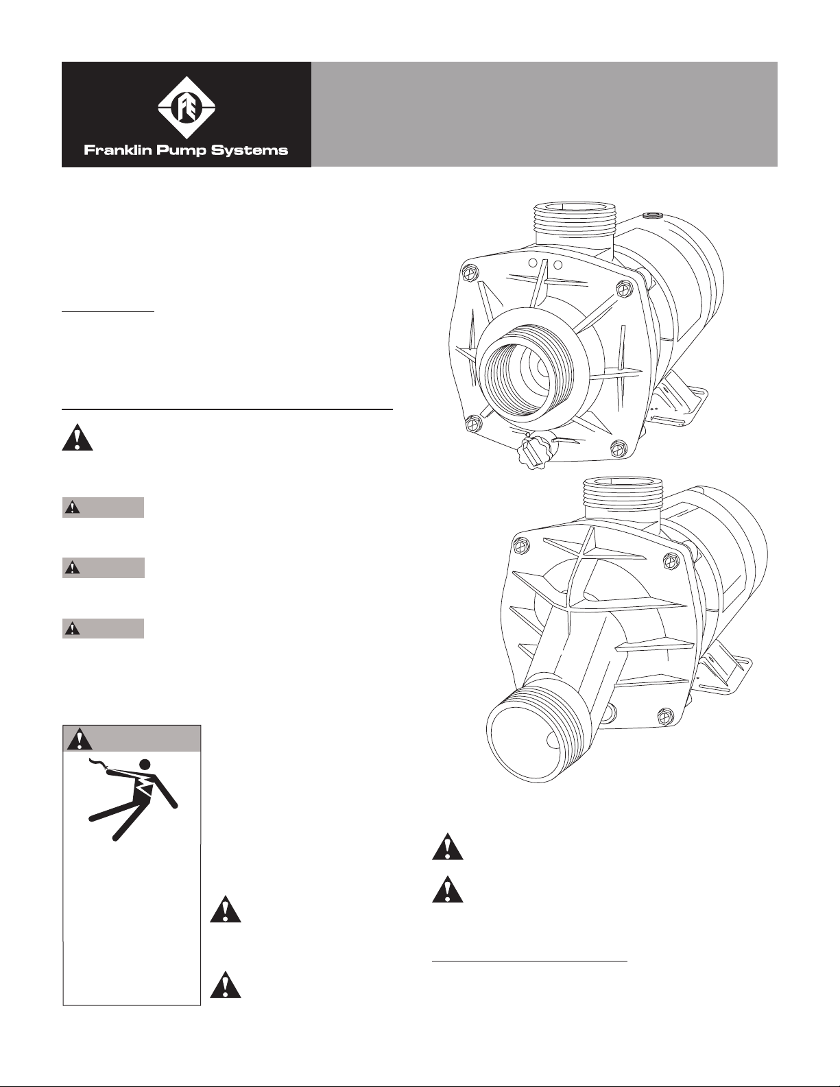
INSTALLATION LOCATION
All S & J Series pumps are designed for fl ooded suction
(all suction fi ttings and suction piping are below water
level) and will not self-prime.
Page 2
GENERAL PLUMBING
FOR SOLVENT WELD CONNECTIONS
Rigid or fl exible PVC pipe can be used. Pipe ends
should be clean and free of any fl ash caused by the
cutting operation. Be sure that the proper adhesive is
used on the type of pipe specifi ed.
Recommended Adhesives- These are examples only
and are not intended to restrict brands.
PVC-PVC JOINT PVC-ABS JOINT
Uni-weld Pool-Tite 2000 Uni-weld Pool-Tite 2000
Suregard Flex 20 Suregard Weld-all No. 5
IPS Weld-on 705 IPS Weld-on 794
NOTE: A Primer will assure that adhesives joints are
superior. Sureguard P-3000 has a purple tracer to qualify
in areas where codes specify a primer must be used.
CAUTION- We recommend that you consider
climatic conditions when applying adhesives. Certain
atmospheric situations, such as high moisture content,
make the adhesive action of certain glues less effective.
Check the manufacturer’s instructions.
FOR THREADED CONNECTIONS
Use only Tefl on tape or equivalent on threaded
plumbing connections. Other pipe compounds
may damage threads. We do not recommend the
use of silicone or petroleum based compounds.
DO NOT OVER TIGHTEN! HAND TIGHTEN PLUS 1/2
TURN IS SUFFICIENT.
PUMP PLUMBING
All S & J Series pumps are union connected allowing
quick and easy service without disturbing the plumbing.
Two different plumbing confi gurations are available
offering 1-1/2” suction connection and either 1-1/2”
discharge or 1” tee discharge. These union packages
must be ordered separately. Avoid using a suction pipe
smaller than pump connection.
To maximize the 100% drain feature, keep the piping as
straight and short as possible, and slope horizontal runs
so water drains away from pump. The suction line must
be installed at an elevation below the water level when
the tub is fi lled to guarantee fl ooded suction.
ELECTRICAL DATA
Refer to information on motor nameplate for electrical
service data. All motors should have fused disconnect
switch or circuit breaker. Be sure wire size is suffi cient
for HP and distance from power source. Wiring should
be done in accordance with applicable codes by
competent electrician. We recommend the installation of
a ground fault circuit interrupter for maximum safety.
PUMP START UP
Fill tub to desired level making sure that suction fi ttings
and jets are below water level. Start pump and open all
suction and discharge line valves.
After about 10 minutes of operation, check the return
fi ttings for air bubbles. A continuous fl ow of air indicates
leaks in the suction line. Locate and correct any
leaks immediately.
CAUTION- Do not operate pump with closed suction
or discharge valves.
TWO-SPEED PUMPS
Two-speed models are recommended in a swimming
pool when high speed is needed for maximum fi ltration
at peak periods and whenever turbidity levels are high.
At other times, switch to low speed. For backwashing
and vacuuming, high speed is required.
In spa and hot tubs, use high speed to atain full
performance in the hydro-therapy mode. At other times,
such as fi lter/heat cycle mode, use low speed. Low
speed provides suffi cient fl ow to activate most spa
heaters and provides suffi cient fl ow for fi ltration.
In jetted tubs, use high speed to attain full performance
in the hydro-therapy mode and use low speed for
desired low fl ow conditions.
NOTE: Two-speed pumps must be in high speed
mode to prime.
PUMP MAINTENANCE
1. Motors are self-lubricating-- no lubrication is required.
2. Clean Hair & Lint Strainer if you have a pump with
strainer body.
3. Visually inspect motor for blockage of air vents
on motor shell. Remove any debris after shutting
off breaker.
4. Shaft seals may become worn and must be replaced
if leakage is observed.
SERVICE AND REPAIR PARTS
Refer all service to your local dealer as his knowledge
of your equipment makes him the best qualifi ed source
of information. Order all repair parts through your
dealer. Give the following information when ordering
repair parts.
1. Unit nameplate data
2. Description of part
1
Page 3

TROUBLESHOOTING
MOTOR DOES NOT START
1. Disconnect switch or circuit breaker in OFF position.
2. Fuses blown or thermal overload open.
3. Locked motor shaft.
4. Motor windings burned out.
5. Defective starting switch inside single-phase motor.
6. Disconnected or defective wiring.
7. Low voltage.
MOTOR DOES NOT REACH FULL SPEED
1. Low voltage.
2. 2 speed model set on low speed.
3. Motor windings connect for wrong voltage on dual
voltage model.
MOTOR OVERHEATS (Protector trips)
1. Low voltage.
2. Motor windings connected for wrong voltage on dual
voltage model.
3. Inadequate ventilation.
PUMP DELIVERS NO WATER
1. Pump is not primed.
2. Closed valve in suction or discharge line.
3. Leakage of air into suction line.
4. Impeller Clogged.
LOW PUMP CAPACITY
1. Valve in suction or discharge line partly closed.
2. Suction or discharge line partly plugged.
3. Suction or disharge line too small.
4. Pump running at reduced speed (see above)
5. Impeller clogged.
LOW PUMP PRESSURE
1. Pump running at reduced speed (see motor)
2. Discharge valve or inlet fi ttings open too wide.
HIGH PUMP PRESSURE
1. Discharge valve or inlet fi ttings closed too much.
2. Return lines too small.
NOISY PUMP AND MOTOR
1. Worn motor bearings.
2. Valve in suctin line partly closed.
3. Suction line partly plugged.
4. Pump not supported properly.
LEAKAGE OR WATER AT SHAFT
1. Shaft seal requires replacement.
AIR BUBBLES AT INLET FITTINGS
1. Leakage of air into suction line at connections or
valve system.
2. Restriction in suction line.
LEAKING UNIONS
1. O-ring missing or damaged.
2. Plumbing in bind.
3. Insuffi cient tightening.
NOTE: If the recommendations in the Troubleshooting
portion of this manual do not solve your particular
problem(s), please contact your local dealer for
service.
2
Page 4

PARTS FOR MODEL J, JCM, S, and SKM
8
7a
2
4
5
6
3
7
Figure No. Part No. Description
9010-1197-R Motor 3/4HP 115/1/60 48Y Frame
1
2
3 47-0357-46-R O-ring 5-1/2 x 5-7/8 x 3/16
4 10-0002-06-R 5/8 Mechanical Seal
5
6 10-1462-07-R Eye Seal
7
7a 11-1517-01-R SKM Flange 2-1/2” butt with 1/4’ plug 31160906R
8
9010-1247-R Motor 1HP 115/1/60 48Y Frame
9010-0710-R Motor 1-1/2HP 115/1/60 48Y Frame
02-1308-05-RKIT J Bracket Kit (incl. #7 3-10 butt & #8 1/4-14 x 1-1/8 fasteners)
02-1309-04-R JCM & SKM Bracket (eff. 2/1/94) 1/4-14 Thrd, 2-1/2 butt
02-1613-05-R JCM & SKM Bracket (eff. prior 2/1/94) 1/4-20 Thrd, 2-1/2 butt
05-3862-06-R Impeller S7J, S7K #11343 3.45D
05-3863-05-R Impeller S1J, S1K #11343 3.73D
05-3864-04-R Impeller S15J, S15K #11343 4.10D
05-3865-03-R Impeller S2J, S2K #11304 4.22D
03-0651-09-R J Flange 3-10 butt
03-0854-04-R JCM Flange 2-1/21-8 butt
14-1266-35-R Fastener 1/4-20x3/4 4 required, Eff, for units prior to 2/1/94 “J” model
14-4339-08-R J, JCM and SKM Fastener 1/4-14 x 1-1/8
1
3
Page 5

U.S. LIMITED WARRANTY*
Franklin Pump Systems, Inc.
Franklin Pump Systems, Inc. warrants its new products to be free of defects in material and workmanship for a
period of 1 year from date of installation or 2 years from date of manufacture, whichever comes fi rst, WHEN installed in
a domestic water systems application and pumping potable water only. Warranty does not cover applications pumping
saltwater or other corrosive liquids. Consult and adhere to local codes for all applications. Franklin Pump Systems, Inc.
also provides additional warranty coverage on specifi c products as specifi ed herein.
Franklin Pump System’s warranty obligation with regard to equipment not of its own manufacture is limited to the
warranty actually extended to Franklin Pump System by its suppliers.
This warranty extends only to the original retail purchaser and only during the time in which the original retail
purchaser occupies the site where the product was originally installed.
Requests for service under this warranty shall be made by contacting the installing Franklin Pump System
dealer (point of purchase) as soon as possible after the discovery of any alleged defect. Franklin Pump System will
subsequently take corrective action as promptly as reasonably possible.
Franklin Pump System at its discretion may replace or repair any product that fails under this warranty after
inspection by an authorized company representative or after Franklin Pump System has received the product at our
factory. Replacement or repair cannot be made until after the product is inspected. All charges or expenses for freight
to and from the factory, removal and reinstallation of the product, or installation of a replacement product are the
responsibility of the purchaser.
THIS WARRANTY SUPERSEDES ANY WARRANTY NOT DATED OR BEARING AN EARLIER DATE. ANY
IMPLIED WARRANTIES WHICH THE PURCHASER MAY HAVE, INCLUDING MERCHANT ABILITY AND FITNESS
FOR A PARTICULAR PURPOSE, SHALL NOT EXTEND BEYOND THE APPLICABLE WARRANTY PERIOD. Some
states do not allow limitations on how long an implied warranty lasts, so the above limitation may not apply
to you. IN NO EVENT SHALL FRANKLIN PUMP SYSTEM BE LIABLE FOR INCIDENTAL OR CONSEQUENTIAL
DAMAGES. Some states do not allow the exclusion or limitation of incidental or consequential damages, so the
above may not apply to you.
This warranty does not apply to any product which has been subjected to negligence, alteration, accident, abuse,
misuse, improper installation, vandalism, civil disturbances, or acts of God. The only warranties authorized by Franklin
Pump System are those set forth herein. Franklin Pump System does not authorize other persons to extend any
warranties with respect to its products, nor will Franklin Pump System assume liability for any unauthorized warranties
made in connection with the sale of its products.
THIS WARRANTY GIVES YOU SPECIFIC LEGAL RIGHTS, AND YOU MAY ALSO HAVE OTHER RIGHTS WHICH
MAY VARY FROM STATE TO STATE.
* Contact Franklin Pump Systems, Inc. Export Division for International Warranty.
E1429 7/05
12401 Interstate 30 • P.O. Box 8903
Little Rock, AR 72219
4
Page 6

Page 7

Page 8

 Loading...