

Page 1
Constant Pressure Water System
SubDrive300
Installation Manual
Page 2

Contents
Description and Features ................................................................................4
Included Items ..................................................................................................5
How It Works .....................................................................................................6
Pump Sizing and Drive Confi guration ............................................................8
Underload Sensitivity for Shallow Wells ........................................................9
Before Getting Started ...................................................................................10
Controller Location Selection ................................................................. 11-12
Circuit Breaker and Wire Sizing ....................................................................13
Quick Reference Guide ............................................................................ 14-15
Pressure Tank .................................................................................................16
Installation Procedure ....................................................................................17
Wiring Connections .................................................................................. 18-20
Start-Up and Operation .................................................................................21
Specifi cations .................................................................................................22
Mounting Dimensions ....................................................................................23
Diagnostic Fault Codes ..................................................................................24
System Troubleshooting Guide .....................................................................25
Underload Smart Reset .................................................................................26
Over Temperature Foldback ..........................................................................26
Tables
1. SubDrive Models .......................................................................................3
2. Breaker Size and Maximum Cable Length ...........................................13
3. Minimum Pressure Tank Size .................................................................16
4. Pressure Tank Precharge .......................................................................16
2
Figures
1. Shipping and Mounting Screws .............................................................17
2. Motor Lead Connections .......................................................................18
3. Power and Pressure Sensor Connections ............................................19
4. Pressure Sensor ......................................................................................20
5. Underload “Smart Reset” Well Recovery Time ....................................26
Page 3

Table 1: SubDrive Models
Model Name Part Number Use with Motor Series
SubDrive300 5870206300 (NEMA 4) 234 317 xxxx (5.0 Hp)
3
Page 4
Description and Features
The Franklin Electric SubDrive300 is a dependable residential and light
commercial water system controller that uses advanced electronics to
enhance the performance of standard submersible pumps. When used with
the specifi ed Franklin Electric motor (see Table 1), the SubDrive eliminates
pressure cycling associated with conventional water well systems and
owners of private water well systems can enjoy “city-like” water pressure.
In addition, the reduced tank size (see Table 3) allows installation in small
spaces. Key features of the SubDrive include:
4
• Constant water pressure with a wide range of settings (25-80 psi)
• Smaller pressure tank can be used
• Fits the pump to the application – pump speed is controlled to
provide the optimum performance without overloading the motor
• Flexibility – you can use this unit with standard off-the-shelf pumps
• No in-rush (power-on transient) current
• Low motor start-up current (soft-starting)
• Active Power Factor Correction minimizes input RMS current
• Protection features
- Dry well conditions – using smart pump monitoring (see Page 26)
- Bound pump – with auto-reversing torque
- High voltage / lightning surge
- Low line voltage
- Open motor circuit
- Short circuit
Page 5
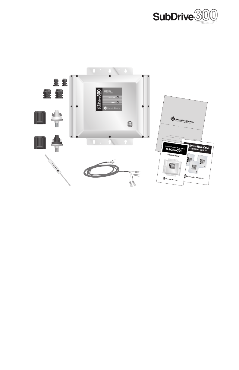
Included Items
A
B
C
D
I
Franklin
Ele
ctri
c is n
Sub
ow o
Driv
e 150 and M
f
fer
ing an int
Driv
e must
onoDr
rod
uct
ive.
ory
be
warran
registered with Franklin
The
sio
ex
n.
•
If a S
ubD
rive is
not
to excee
•
The
re
gist
ration card
•
As with
our standard
ship.
•
Thi
s Ext
ended W
SubDrive Extended W
T
erm
of wa
rranty: 3
must be
Y
ears
regist
from date o
ered
within
30
days
Product
Ins
tal
led (check one):
Instal
lation Name / Own
er
Instal
lation
Add
ress
Ins
tal
ler
Instal
ler
Add
ress
Dist
ribu
tor
Date
of I
nstallation
SubD
rive/Mon
oDrive Serial
Nu
mber
(exampl
This warranty
card
Street,
must be return
Bluffto
n,
warrant
ed t
IN 46
o
714
Franklin Electric,Att
y
.
by
mail,
or faxe
d to
260-
ty exte
ten
ded war
nsion
ran
on S
ty i
Ele
ubDriv
s f
ree,
ctri
c in order t
e 75,
bu
t the
Su
o activat
y f
tur
ten
ded wa
rive 75
arrant
t to excee
0
3
3
8
0
)
e Code
Pu
Coordinat
his f
orm must
or tha
t un
it
covers
e date.
ranklin Elect
ric
rranty covers
, SubDrive 150
y Reg
d 4 years from manufacture dat
?
SubDrive 15
Phone Nu
State Zip
Phone Nu
State Zip
Phone Nu
(example:
01A23
)
mp Mfg.
/ Mod
el
or –
Sub
Drive Products,
be
fill
ed
out
bDriv
e/M
e the war
ono
-
ran
ty exte
n
-
3 year
s from t
he
date of i
nstallatio
n,
no
later
tha
n 30 days
afte
r i
nstallati
def
ects i
on.
n material
an
d workman
-
an
d MonoD
rive con
tro
llers.
istrati
01000
on
e. Warra
nty
0
(
5
8
7
0
2
0
4
1
5
0
)
?
MonoDrive
( )
mber
mber
mber
( )
400
to val
E. Sprin
idate t
g
he e
xten
d
ed
registere
d, t
he
d
4 year
warrant
s from i
ts manufac
must
be
returned to F
warrant
y
, the ex
arr
ant
y covers only SubD
Cut or fold here
f in
stal
lation, no
of i
nstallatio
n date.
?
SubDrive 75
(
5
8
7
0
2
City
Cit
y
SubDrive Dat
e: 00
0451
)
n: In
side Sales
827-5
800
.All
fie
lds in t
E
F
A. Controller Unit
B. Strain Relief Fittings
C. Pressure Shut-off
Sensor and Boot
D. Pressure Sensor and Boot
G
E. Sensor Adjustment Tool
F. Sensor Cable
G. Installation Manual
H. Installation Guide
I. Warranty Card
H
5
Page 6
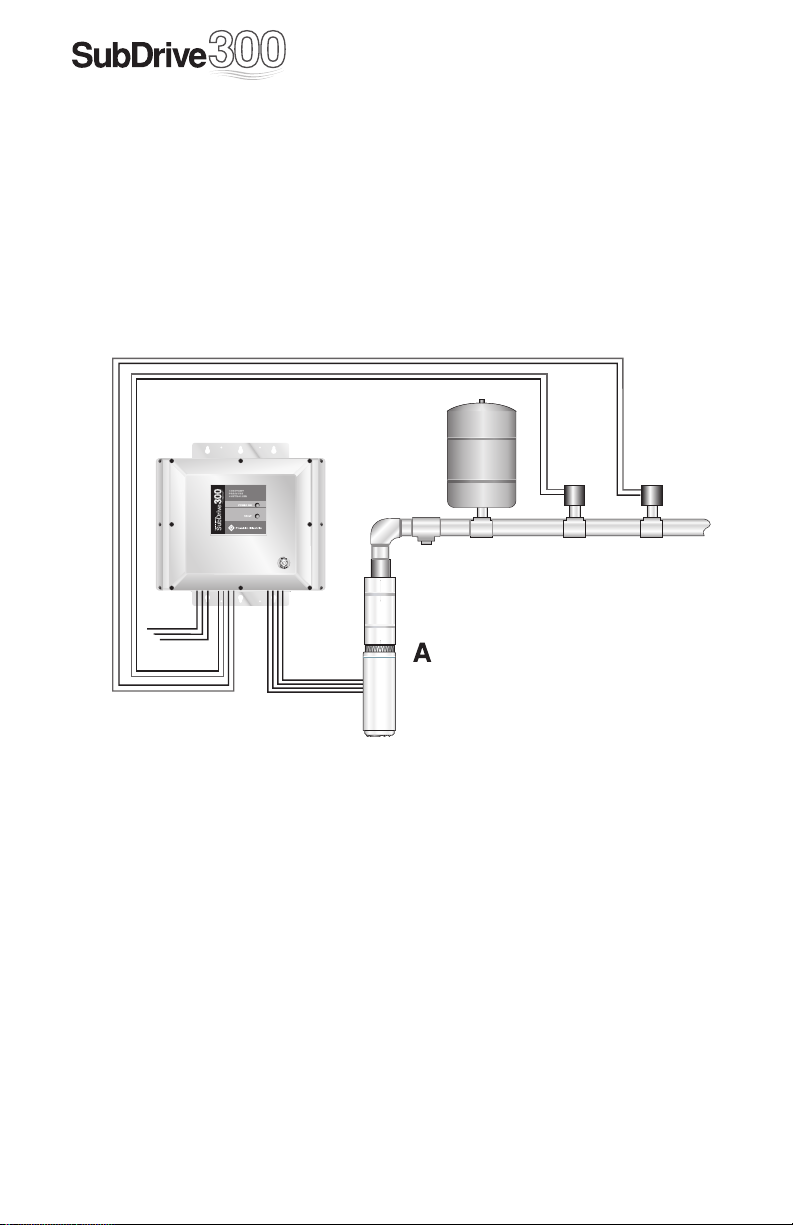
How It Works
The Franklin Electric SubDrive300 is designed to be part of a system that
consists of only four components:
A. Standard Pump and Franklin Electric Motor.
B. SubDrive Controller.
C. Small Pressure Tank (for tank size, see Table 3).
D. Franklin Electric Pressure Sensor (provided).
E. Franklin Electric Pressure Shut-Off Sensor (provided).
B
Pressure
C
Sensor
Leads
Pressure
Shut-o
Sensor
Leads
DE
Pressure
Relief Valve
PUMP
Power Supply
From Circuit Breaker
Constant Pressure
The Franklin Electric SubDrive300 provides consistent pressure regulation
using advanced electronics to drive a standard motor and pump according
to the pressure demands indicated by a highly accurate, heavy-duty,
long-life pressure sensor. By adjusting the motor/pump speed, the
SubDrive300 can deliver constant pressure dependably, even as water
demand changes. For example, a small demand on the system, such as
a bathroom faucet, results in the motor/pump running at a relatively low
speed. As greater demands are placed on the system, such as opening
additional faucets or using appliances, the speed increases accordingly to
maintain the desired system pressure.
MOTOR
6
Page 7

Motor Soft Start
Normally, when there is a demand for water, the SubDrive300 will
be operating to accurately maintain system pressure. Whenever the
SubDrive300 detects that water is being used, the controller always “ramps
up” the motor speed while gradually increasing voltage, resulting in a cooler
motor and lower start-up current compared to conventional water systems.
In those cases where the demand for water is small, the system may cycle
on and off at low speed. Due to the controller’s soft-start feature and
sensor’s robust design, this will not harm the motor or the pressure sensor.
System Diagnostics
In addition to regulating pump pressure and accurately controlling motor
operation, the SubDrive300 continuously monitors system performance and
can detect a variety of abnormal conditions. In many cases, the controller
will compensate as needed to maintain continuous system operation. But
if there is high risk of equipment damage, the controller will protect the
system and display the fault condition. If possible, the controller will try to
restart itself when the fault condition subsides.
Unique Features
SubDrive controllers provide the ultimate in system performance, utilizing
Franklin Electric’s three-phase motor series for maximum starting torque,
high effi ciency and smooth operation. SubDrives convert residential single-
phase 60Hz power into the variable-frequency three-phase needed by the
motor. In addition, SubDrives can spin a smaller pump slightly faster to
boost output to roughly double its 60Hz horsepower rating. This allows use
of smaller pumps for less system cost. If a smaller pump of the desired fl ow
rating is not available, the controller can be confi gured to use larger pumps
up to the horsepower rating of the motor.
7
Page 8
Pump Sizing
The SubDrive300 is confi gured at the factory for use with 3 Hp pumps that
are mounted to 5 Hp Franklin Electric three-phase motors. In general, the
SubDrive300 will enhance the performance of a 3 Hp pump to a similar
or better performance than a conventional 5 Hp pump of the same
fl owrating (pump series).
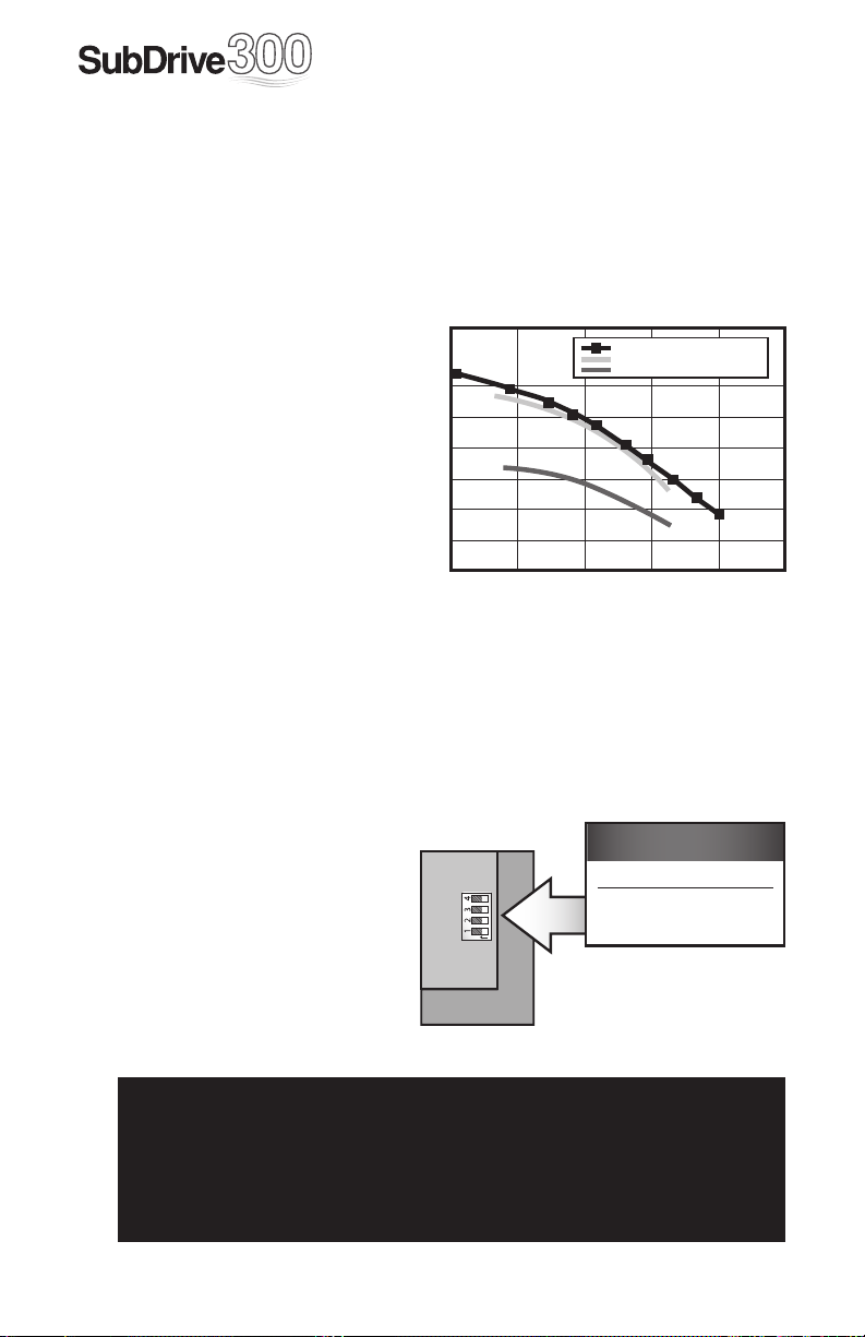
To select the proper 3 Hp
pump, fi rst choose a 5 Hp
curve that meets the
application’s head and fl ow
requirements. Use the 3 Hp
pump in the same pump
series (fl ow rating). The
SubDrive300 will adjust the
speed of this pump to
produce the performance
of the 5 Hp curve. An
example of this is
illustrated in the graph at right.
Typical SubDrive300 Performance
700
600
500
400
300
Total Head (ft)
200
100
51530456075
)Q(1.XJUI4VC%SJWF
$POWFOUJPOBM)Q(1.1VNQ
$POWFOUJPOBM)Q(1.1VNQ
Flow GPM
Drive Confi guration
The SubDrive300 can also be set up to run a 5 Hp pump if desired, but the
larger pump will still produce to the 5 Hp curve and may only be operated
with a 5 Hp motor. To operate a different pump size, a DIP switch must be
positioned to select the correct pump rating. Otherwise, the SubDrive300
may trigger erroneous faults.
To confi gure the SubDrive300
for a 5 Hp pump, locate the DIP
switch marked “SW1” at the
lower right corner of the main
circuit board. Use a small
screwdriver (provided)
to change the DIP switch
setting according to the chart
as shown.
SW1
N
O
Configuration Switch
1 Pump Size
OFF 3.0 Hp
ON 5.0 Hp
8
!
▲ WARNING
Serious or fatal electrical shock may result from contact with internal
electrical components. DO NOT, under any circumstances, attempt
to modify DIP switch settings until power has been removed and 5
minutes have passed for internal voltages to discharge!
Page 9
Underload Sensitivity for
Shallow Wells
The SubDrive300 controller is confi gured at the factory to ensure detection
of Underload faults in a wide variety of pumping applications. In rare cases
(as with certain pumps in shallow wells) this trip level may result in nuisance
faults. If the pump is installed in a shallow well, activate the controller and
observe system behavior. Once the controller begins to regulate pressure,
check operation at several fl ow rates to make sure the default sensitivity
does not induce nuisance Underload trips.
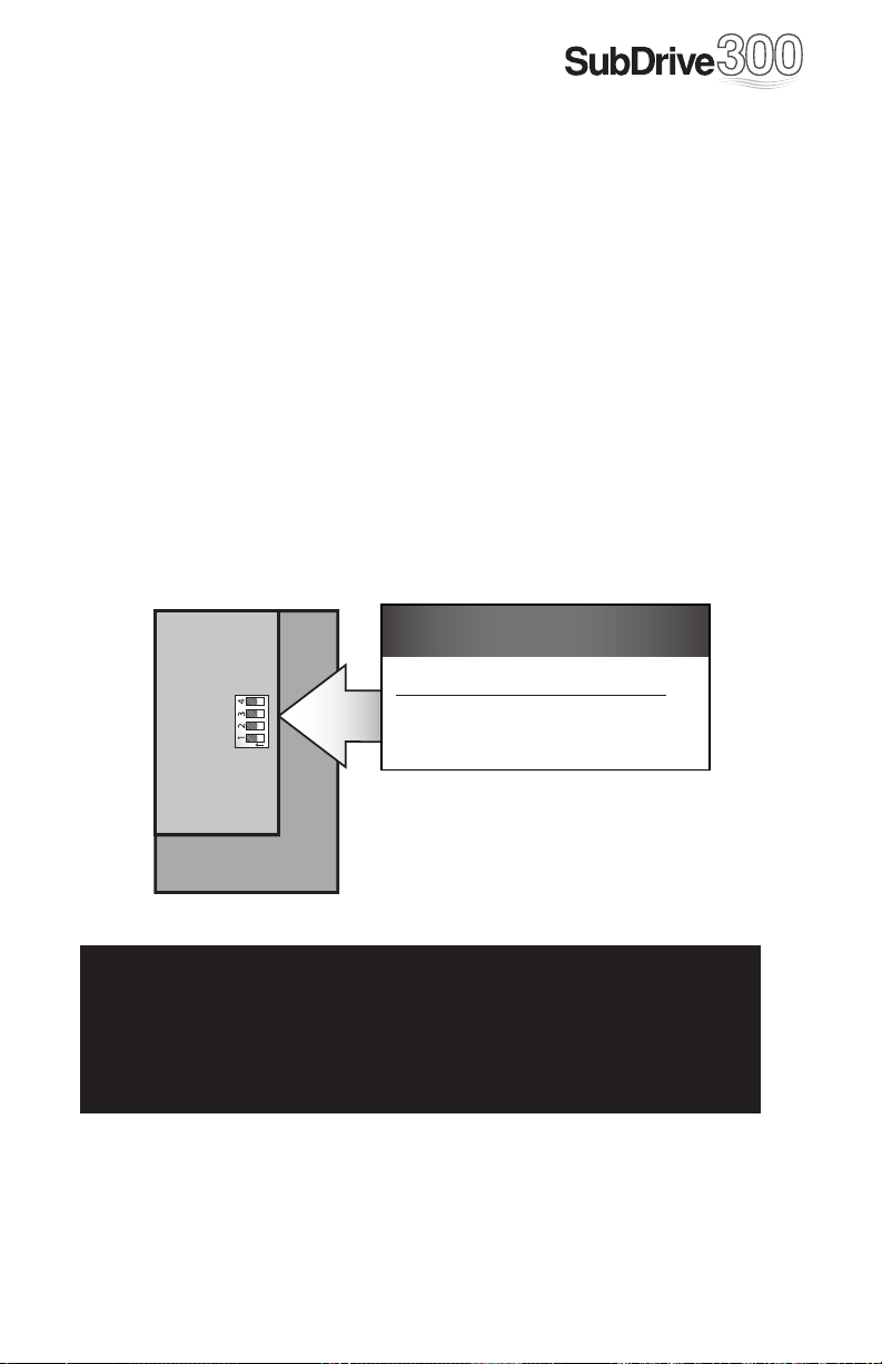
If it becomes necessary to desensitize the Underload trip level, remove
power and allow the controller to discharge. Once the internal voltages have
dissipated, locate the DIP switch marked “SW1” at the lower right corner
of the main circuit board. Use a small screwdriver (provided) to change
Position 3 to the “ON” position to select the lower Underload sensitivity as
shown in the chart below.
Configuration Switch
POS Underload Sensitivity
SW1
N
O
!
▲ WARNING
Serious or fatal electrical shock may result from contact with internal
electrical components. DO NOT, under any circumstances, attempt
to modify DIP switch settings until power has been removed and 5
minutes have passed for internal voltages to discharge!
3 OFF Normal (default)
ON Low (shallow wells)
9
Page 10

Before Getting Started
!
▲ WARNING
Serious or fatal electrical shock may result from failure
to connect the ground terminal to the motor, SubDrive
controller, metal plumbing, or other metal near the motor
or cable, using wire no smaller than motor cable wires. To
minimize risk of electrical shock, disconnect power before
working on or around the SubDrive300 system.
CAPACITORS INSIDE THE SUBDRIVE300 CONTROLLER CAN STILL HOLD LETHAL VOLTAGE EVEN AFTER
POWER HAS BEEN DISCONNECTED.
ALLOW 5 MINUTES FOR DANGEROUS INTERNAL
VOLTAGE TO DISCHARGE BEFORE REMOVING
SUBDRIVE300 COVER.
Do not use motor in swimming areas.
!
▲ ATTENTION
This equipment should be installed by technically qualifi ed
personnel. Failure to install it in compliance with national
and local electrical codes and within Franklin Electric
recommendations may result in electrical shock or fi re
hazard, unsatisfactory performance, or equipment failure.
Installation information is available through pump
manufacturers and distributors, or directly from Franklin
Electric at our toll-free number 1-800-348-2420.
10
!
▲ CAUTION
Use SubDrive300 only with Franklin Electric 4-inch
submersible motors as specifi ed in this manual (see Table
1). Use of this unit with any other Franklin Electric motor or
with motors from other manufacturers may result in damage to both motor and electronics.
Page 11

Controller Location Selection
The SubDrive controller is intended for operation in ambient temperatures
up to 125°F (51°C) at 230 VAC input. The following recommendations will
help in selection of the proper location of the SubDrive unit:
1. A tank tee is recommended for mounting the tank, pressure sensor,
pressure gauge, and pressure relief valve at one junction. If a tank
tee is not used, the pressure sensor should be located within 6 feet
(1.8 meters) of the pressure tank to minimize pressure fl uctuations.
There should be no elbows between the tank and pressure sensor.
2. The unit should be mounted on a sturdy supporting structure such as a
wall or supporting post. Please take into account the weight of the unit,
which weighs approximately 34 pounds (15.5 kg).
3. The electronics inside the SubDrive are air-cooled. As a result, there
should be at least 6 inches of clearance above and below the unit to
allow room for air fl ow.
!
▲ CAUTION
There should be at least 6 inches of clearance above and below the
unit to allow room for air fl ow.
6"
min.
Pressure
Shut-off
Sensor
*
6"
min.
Clearance
For
Air Flow
PUMP
MOTOR
Pressure
Tank
Pressure
Relief Valve
Pressure
Sensor
6 Feet or Less
(Pressure Tank to PressureSensor)
* NOTE: there should be no elbows between the tank and pressure sensor.
11
Page 12

Power Supply
From Circuit Breaker
Pressure Sensor
Wiring
4. For indoor or outdoor installations.
5. The SubDrive300 should only be mounted with the wiring end
oriented downward. The controller should not be placed in direct
sunlight or other locations subject to direct rain or snow.
6. The mounting location should have access to 230 VAC electrical
supply and to the submersible motor wiring. To avoid possible
interference with other appliances, please refer to the enclosed
Installation Guide and observe all precautions regarding power
cable routing.
7. To assure maximum weather protection, the unit must be mounted
vertically with the cover properly aligned and secured with all eight
lid screws.
Wiring
To M oto r
Wiring
To M oto r
CORRECT INCORRECT
Pressure Sensor
Wiring
Power Supply
From Circuit Breaker
12
Page 13

Circuit Breaker and Wire Sizing
The minimum circuit breaker size and maximum allowable wire lengths for
connection of motor to the SubDrive300 are given in the following table:
Table 2: Minimum Breaker Size and Maximum Cable Length (in Feet)
Controller
Model
SubDrive300 234 317 xxxx 5 40 140 230 370 590 920 1430
A 10-foot section of cable is provided with the SubDrive300 to connect
the pressure sensors.
NOTE:
• Maximum allowable wire lengths are measured between the
• Aluminum wires should not be used with the SubDrive300.
• Wire sizing between the service entrance and the controller must
• SubDrive300 minimum breaker amps may be lower than AIM
Franklin Electric
Motor Model HP
controller and motor.
be suffi cient to provide the required maximum input amps to the
controller while conforming to local standards and codes.
Manual specifi cations for the motors listed due to the soft-starting
characteristic of the SubDrive300 controller.
Breaker
Amps
AWG Copper Wire Size
14 12 10 8 6 4
13
Page 14

Quick Reference Guid
e
u
a
e
o
a
u
From Power Source
L1 L2
(Input)
Power Supply
From Circuit Breaker*
P/N 587 020 6300
PRESSURE
INT
NO NO
FAN
SENSOR
SHUT-OFF
RELAY
COM
INV
PFC
FAN
FAN
Sensor Connection
PRESSURE
SENSOR
BlkRed GrnWh
SW1
O
SW2
PRESSURE
SHUT-OFF
Congur
1
N
OFF
ON
Outp
NOTICE
The Safety earth ground connections
are marked at their terminals using
the “ ” symbol
* Note: To avoid possible interference with other appliances,
please refer to the enclosed installation guide and observe all
precautions regarding power cable routing
14
P
Fr
El
M
Page 15

SubDrive300 (not to scale)
a
tion Switch
Pump Size
3.0 Hp
5.0 Hp
t to Motor
Red Yel Blk
(Brn) (Blu e) (Blk)
(Output)
mp
nklin
ctric
tor
Tank Precharge
Ination Valve
minimum tank size
Pressure Gauge
Pressure
Relief Valve
Discharge into
drain rated for
max pump output
at relief pressure
WARNING
Submersible pumps can
develop very high pressure in
some situations. Always
install a pressure relief valve
able to pass full pump ow at
100 PSI. Install the pressure
relief valve between the
pump and pressure tank.
Pressure Tank
See Table 3
(page 16) for
recommened
Pressure
Sensor
Pressure
Shut-o
Sensor
Drain Valve
Pressure Setting Guide
Pressure Switch
Set Point (PSI)
25
30
35
40
45
50 (Factory set)
55
60
65
70
75
80
Sensor Cable
Supplied
Pressure Tank
Pre-Charge (PSI)
To Residence
18
21
25
28
32
35
39
42
46
49
53
56
15
Page 16

Pressure Tank
The SubDrive needs only a small pressure tank to maintain constant
pressure (see table below for recommended tank size). For pumps rated 12
gpm or more, a slightly larger tank is recommended for optimum pressure
regulation. The SubDrive can also use an existing tank with a much larger
capacity
Table 3: Minimum Pressure Tank Size (Total Capacity)
The pressure tank pre-charge setting should be 70% of the system pressure
sensor setting as indicated in the following table.
Table 4: Pressure Tank Precharge (PSI)
.
Pump Flow Rating Controller Model Minimum Tank Size
Less than 12 gpm SubDrive300 8 gallon
12 gpm and higher SubDrive300 20 gallon
System Pressure
(at Pressure Sensor)
25 18
30 21
35 25
40 28
45 32
50 35 Factory Setting
55 39
60 42
65 46
70 49
75 53
80 56
NOTE: Check tank precharge regularly to maintain optimum
pressure regulation.
Pressure Tank
Setting (±2 psi)
16
Page 17

Installation Procedure
1. Disconnect electrical power at the main breaker.
2. Drain the system (if applicable).
3. Install the pressure sensor and pressure shut-off sensor at the
pressure tank tee downstream of the pressure tank (the pressure
tank should be between the pressure sensor and the pump). The
sensors have a ¼-18 National Pipe Thread (NPT) connection.
The pressure sensors should not be installed in an inverted
orientation (up-side down). Make sure the pressure sensor and tank
are not located more than 3 feet off the main piping.
4. Install the unit to the wall using four mounting screws (not included) as
shown in Figure 1 below. Remove the SubDrive lid by removing the eight
lid screws.
Mounting Screw Locations
Lid Screws (Included Quantity 8)
(User Supplied Quantity 4)
Figure 1: Mounting Screws
17
Page 18

Wiring Connections
!
▲ WARNING
Serious or fatal electrical shock may result from failure to connect
the motor, the SubDrive300, metal plumbing and all other metal near
the motor, or cable to the power supply ground terminal, using wire
no smaller than motor cable wires. To reduce risk of electrical shock,
disconnect power before working on or around the water system.
Do not use motor in swimming areas.
1. Verify that the power has been shut off at the main breaker.
2. Verify that the dedicated branch circuit for the SubDrive300 is
equipped with a properly-sized circuit breaker. Refer to Table 2
(Page 13) for minimum breaker size.
3. Use the appropriate strain relief or conduit connectors. Type B liquid
tight fi ttings are recommended for maximum weather protection.
4. Remove the SubDrive300 lid.
5. Feed the motor leads through the opening on the bottom right side
of the unit and connect them to the terminal block positions marked
GND (Green ground wire), Red, Yellow and Black (Figure 2).
18
SW1
N
O
SW2
PRESSURE
INT
NO NO
FAN
SENSOR
SHUT-OFF
RELAY
COM
INV
PFC
FAN
FAN
Figure 2: Motor Lead Connections
Output to Motor
Red Yel Blk
(Brn) (Blue) (B lk)
(Output)
Page 19

SW1
N
O
SW2
From Power Source
PRESSURE
L2L1
(Input)
INT
NO NO
FAN
SENSOR
SHUT-OFF
INV
PFC
FAN
FAN
RELAY
COM
Sensor Connection
PRESSURE
SENSOR
PRESSURE
SHUT-OFF
BlkRed GrnWh
Figure 3: Power and Pressure
Sensor Connections
6. Feed the 230 VAC power leads through the bottom left side of the
SubDrive300 controller and connect them to the terminals marked
L1, L2, and GND (Figure 3).
A 10-foot section of pressure sensor cable is provided with the
controller, but it is possible to use similar 22 AWG wire for distances
up to 100 feet from the pressure sensor. A 100-foot section of
pressure sensor cable is available as an accessory.
7. Feed the pressure sensor leads through the smaller opening located in the
bottom middle of the SubDrive300 unit and press on the quick
connect terminals.
8. Verify that the SubDrive300 unit is properly confi gured for the
horsepower rating of the motor and pump being used. Please refer to
the section on Pump Sizing for information on drive confi guration.
9. Replace the lid. Do not over-tighten the screws.
19
Page 20

Remove Rubber End Cap To Adjust Pressure
With 7/32" Allen Wrench
Pressure
Sensor
Boot
Non-Adjustable
Set at 100PSI
Quick Connect
lead connect
Figure 4A:
Pressure Sensor
Pressure Shut-off Sensor
Figure 4B:
10A. Connect the other end of the pressure sensor cable with the two
spade terminals to the pressure sensor. The connections are
interchangeable (Figure 4A).
10B. Connect the other end of the pressure sensor cable with the two
¼" quick connect terminals to the pressure shut-off sensor. The
connections are interchangeable (Figure 4B).
11. Set the pressure tank pre-charge at 70% of the desired water
pressure setting. To check the tank’s pre-charge, de-pressurize
the water system by opening a tap. Measure the tank pre-charge
with a pressure gauge at its infl ation valve and make the necessary
adjustments.
12. The pressure sensor communicates the system pressure to the
SubDrive300 controller. The sensor is preset at the factory to 50 psi,
but can be adjusted by the installer using the following procedure:
a. Remove the rubber end-cap (Figure 4A).
b. Using a 7/32” Allen wrench (provided), turn the adjusting screw
clockwise to increase pressure and counter-clockwise to
decrease pressure. The adjustment range is between 25 and 80
psi (¼ turn = approximately 3 psi).
c. Replace the rubber end cap.
d. Reset the pressure tank pre-charge to the appropriate pressure.
e. Cover the pressure sensor terminals with the rubber boot
provided (Figure 4A).
20
!
▲ CAUTION
When increasing the pressure, do not exceed the mechanical stop on
the pressure sensor or 80 psi. The pressure sensor may be damaged.
NOTE: Ensure that the system is properly grounded all the way to the service
entrance panel. Improper grounding may result in the loss of voltage surge
protection and interference fi ltering.
Page 21

Start-Up and Operation
Apply power to the controller. A steady green light indicates that the
SubDrive300 has power but the pump is not running. The green
light will fl ash continuously when the pump is running.
Leaky Systems
Leaky water systems might keep the controller running due to the accurate
pressure sensing capability of the pressure sensor. Continuous running
or starts and stops do not hurt the controller, pump or motor. However,
to reduce the on-time of the controller/pump/motor, a “Bump-Mode”
procedure is installed. During low fl ow (or leaky) conditions this feature
periodically increases the speed of the pump several PSI above the set
point and shuts off the pump. This adds some time to bleed off before the
system starts up again.
NOTE: Conventional private water systems intermittently fi ll a pressure
tank as commanded by a standard pressure switch (e.g. 30 - 50 psi). The
SubDrive300 maintains a constant pressure at the pressure sensor up to the
maximum capability of the motor and pump.
Although the pressure is constant at the pressure sensor, pressure drops
may be noticeable in other areas of the home when additional taps are
opened. This is due to restrictions in the plumbing and will be more
pronounced the farther the taps are from the pressure sensor. This would
be true of any system, and if observed, should not be interpreted as a
failure in the performance of the SubDrive300.
21
Page 22

Specifi cations
Voltage 190-260 VAC
Frequency 50/60 Hz
Input from
Power Source
(single-phase)
Current (max) 36 Amps (RMS)
Power Factor 1.0 (constant)
Power (idle) 65 Watts
Power (max) 7200 Watts
Voltage Adjusts with Frequency
Output to Motor
(three-phase)
Pressure Setting
Operating
Conditions
Controller Size
(approximate)
For Use With
(A)
(C)
Frequency Range
Current (max) 17.8 Amps (RMS, each phase)
Factory preset 50 psi
Adjustment range 25-80 psi
NEMA 4 (indoor/outdoor)
Temperature (at 230 VAC
input)
Relative Humidity
Outer dimensions 14 ¾” H × 15 ¾” W × 8 ¾” D
(B)
Weight 34 lbs (15.5kg)
Pump (60Hz)
Motor (3-phase) 234317- series (5.0 Hp)
30-80 Hz (3 Hp pump)
30-60 Hz (5 Hp pump)
Model 5870206300
-13 to 125°F
(-25 to 51°C)
0-100%, non-condensing or
condensing
3.0 Hp (default)
5.0 Hp
NOTES: (A) Operating temperature is specifi ed at full output power when installed as
described in Controller Location Selection on Page 11.
(B) Refer to Page 23 for detailed mounting dimensions.
(C) If a pump other than the default rating is used, refer to Page 8 for
drive confi guration.
22
Page 23

Mounting Dimensions
15.34”
8.75”
14.75”
12.00”
4.75”
23
Page 24

Diagnostic Fault Codes
Should an application or system problem occur, built-in diagnostics will
protect the system. The red “FAULT” light on the front of the SubDrive300
controller will fl ash a given number of times to indicate the nature of the
fault. In some cases, the system will shut itself off until corrective action has
been taken. Fault codes and the recommended corrective action for each
are listed in the following chart.
# of
Flashes Fault Possible Cause Corrective Action
Wait for well to recover and
automatic restart timer to time
out. If the problem does not
correct, check motor and pump.
See description of “Smart Reset”
on Page 26.
Check for loose connections.
Check line voltage. Report low
voltage to the power company.
Unit will start automatically when
the proper power is supplied.
Unit will attempt to free a locked
pump. If unsuccessful, check the
motor and pump.
1
2
3
Motor
Underload
Undervoltage
Locked
Pump
Air-locked pump.
Overpumped or dry well.
Worn pump. Damaged
shaft or coupling. Blocked
pump or screen.
Low line voltage.
Misconnected input leads.
Motor/pump misaligned.
Abrasive/Sand-bound pump.
Dragging pump or motor.
24
4
5
Open Circuit
Short Circuit
6
Over Current
7
** “Cycle input power” refers to turning the power off until both lights fade off,
then applying power again.
Overheated
Controller
Reserved for factory use
Loose connection.
Defective motor or cable.
When fault is indicated
immediately after power-up,
short circuit due to loose
connection, defective cable,
splice or motor.
When fault is indicated
while motor is running, over
current due to loose debris
trapped in pump.
High ambient temperature.
Direct sunlight. Obstruction
of air-fl ow.
Check motor wiring. Make certain
all connections are tight. Make
certain proper motor is installed.
Cycle input power** to reset.
Check motor wiring. Cycle input
power** to reset.
Check pump.
This fault automaticallyresets
when the temperature returns to a
safe level.
Page 25

System Troubleshooting Guide
Symptom Possible Cause Corrective Action
Verify motor connections.
See Figure 2 in the “Wiring
Connections” section.
Make sure there is at least 6” of room
around the controller for movement
of air. Avoid direct sunlight. Reduce
ambient temperature below 125°F
(51°C). Increase input voltage if
below 230 VAC.
Use pump with higher fl ow rating
(if head requirement is still satisfi ed).
Check tank for bladder damage.
Replace if necessary.
Reset the tank pre-charge pressure
(should be 70% of pressure sensor
setting).
Use larger tank
(refer to Table 3 on Page 16 for
minimum Pressure Tank size).
Re-seat the pitless adapter. Replace
seal as needed.
Check for leaky faucets, valves
and/or pipe fi ttings and repair.
Water fl ow rate
is not as high as
expected.
Excessive
pressure
fl uctuations.
Motor runs
continuously with
no fl ow demand.
Motor is running backwards.
Temperature in the controller
is too high. If the controller’s
heat exchanger becomes too
hot, the controller will reduce
the speed of the pump to
lower the power consumption.
Pump capacity cannot supply
the demand.
Waterlogged tank.
Pressure tank is too small for
fl ow rating of the pump.
Leak in the pitless adapter.
Leak in the household or
outdoor plumbing
25
Page 26

Underload Smart Reset
If a motor Underload fault condition occurs, the most likely cause is an
overpumped or dry well. To allow the well to recover, the SubDrive300
controller will wait 30 seconds to 5 minutes, determined by duration of
the previous run time, before restarting the motor. For example, the fi rst
time the fault occurs, the controller will wait 30 seconds before attempting
to restart the pump. If the system would then run for 1 minute and an
Underload fault recurs, the controller will wait 4 minutes before attempting
to restart the pump. This schedule allows for the minimum off-time possible
based on the recovery time of the well.
Figure 5: “Smart Reset” Well Recovery Time
6.0
5.0
4.0
3.0
2.0
Off Time (Min.)
1.0
26
0.0
123 45678
0
Run Time (Min.)
Over-Temperature Foldback
The SubDrive300 controller is designed for full power operation in ambient
temperatures up to 125°F (51°C) as long as the input voltage is kept at 230
VAC. Under extreme thermal conditions, the controller will reduce output
power in an attempt to avoid shutdown. Full pump output is restored when
the controller temperature cools to a safe level.
Page 27

TOLL-FREE HELP FROM A FRIEND
Franklin Electric
Submersible Service Hotline
800-348-2420
Page 28

400 E. Spring Street
Bluffton, IN 46714
Tel: 260-824-2900
Fax: 260-824-2909
www.franklin-electric.com
225286101 Rev. 1
M1491 11.05
 Loading...