

Franke Little Butler LB2200 Series, Little Butler LB3200 Series, Little Butler LB4200 Series Installation And User Manual
Franke Little Butler
Installation and User Guide
Hot Water Dispensing System
Model Series LB2200, LB3200, & LB4200
LB2200
LB3200
LB4200
Franke Consumer Products Inc
Kitchen Systems Division
3050 Campus Drive, Suite 500
Hatfield, PA19440
USA
Phone +1 215 822 6590
Fax +1 215 822 5873
fks.filter@franke.com
www.frankeksd.com
1/4” To 3/8” Reducer
Push Fit
O Ring Seal
Out Of Heating Tank
1/4” Tee Connector
Backnut
Lock Washer
Clamp Plate
Shut Off Valve
Push Fit
*Cut to Length for
Franke Canister
Silicone Tube Hot Water
Into Heating Tank
Cold Water Line
12” Long
Inlet Tubes
Heating Tank
Connections To
Franke Little Butler
Installation, Care and Maintenance
Franke Little Butler
Spare Parts & Warranty
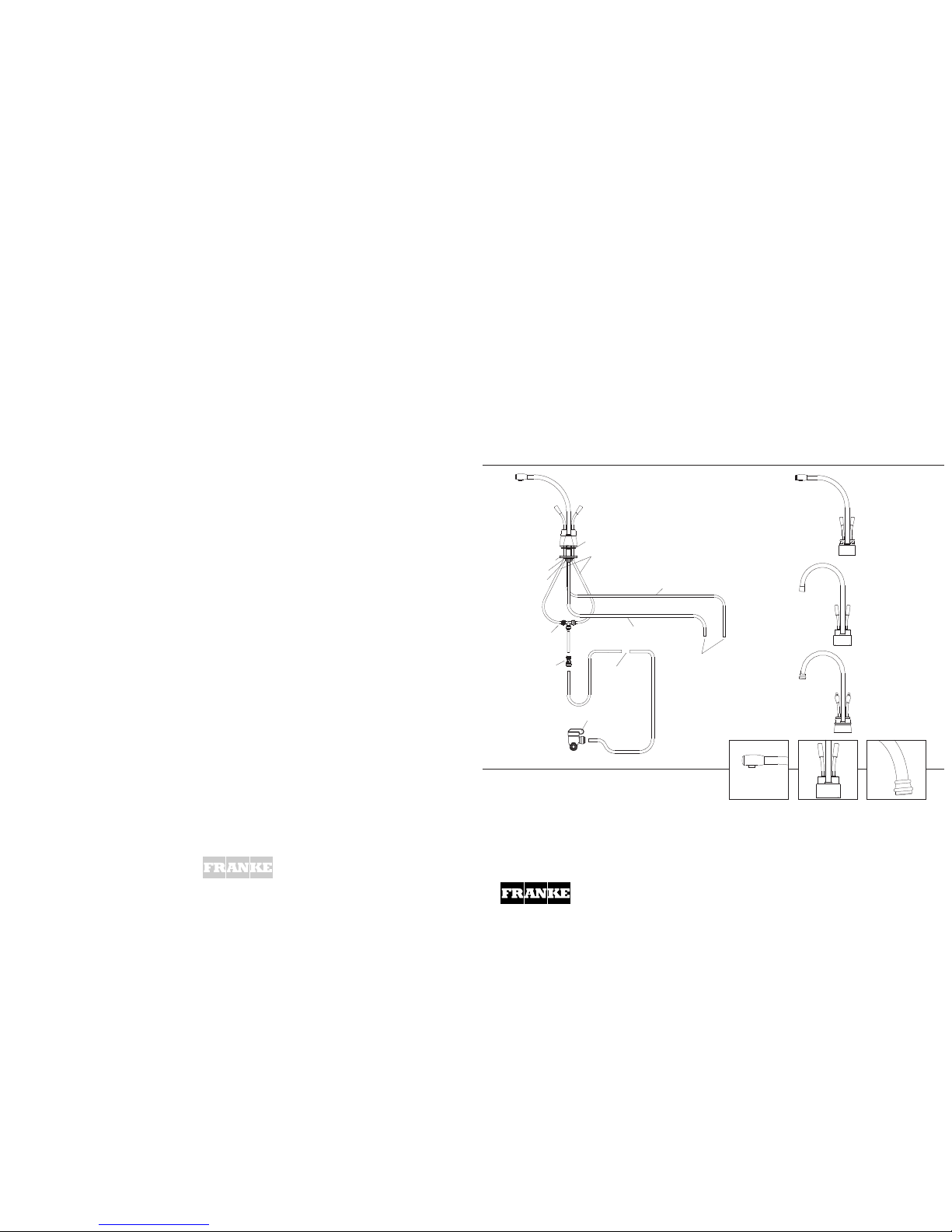
Overview of Installation
There are three main components to the system, the
dispensing head, the canister and the heating tank. The
dispensing head comes with three 1/4” copper tubes and
one silicone tube. The two shorter (12”) copper tubes are
connected to the incoming water supply via the canister.
The supply to the cold side may be diverted through a
chiller before the dispensing head, if required. The
longer (18”) copper tube is connected to the inlet of the
tank. The silicone tube is connected to the outlet of the
tank using the hose connector.
Preparing for the Installation
As with any sink related device, it is much easier to
mount the dispensing head of this system onto the sink
before the sink is mounted into the countertop. A
mounting hole of 1 3/8” diameter (standard sink ledge
drilling) is required.
It is always recommended to take the components and
locate their optimum positions before starting the
installation.
IMPORTANT: Do not plug in the unit until all water
connections have been made and the tank is filled
completely.
Making the Supply Provision
Provide a branch compression connection for a 3/8”
supply tube. This should be done with a conventional tee
and the shut-off valve provided. Flush the pipework
before installing.
Mounting the Dispensing Head
The copper tubes are coiled for packing and must be
carefully straightened before installation. Feed the tubes
and shank through the hole in the sink ledge or counter.
Assemble the clamp plate locking washer and backnut
(hexagon to the top for thin sinks) fingertight. Turn the
dispensing head and the spout until the handles and
spout are in the required position for use and fully tighten
the backnut, this will lock the spout in position.
Seasonal Shutdown
If you plan to be away from home for extended periods
the following procedure must be carried out:
1 Operate the hot lever until the water runs cold.
2 Shut-off the main water supply. A stop valve was
supplied with the system for this purpose, and will be
found located on the adjacent pipe work.
3 Operate both levers to confirm that the water supply is
turned off, and to release the pressure in the system.
Troubleshooting
Should your dispenser not work correctly, check the list
below before calling for service. The following things are
not covered by the warranty.
[WARNING! Do not operate both levers at the same
time as this can build up pressure in the heating
tank causing the bladder to expand and eventually
burst. Such damage is not covered by the w arrant y]
Water is not hot:
Check if electrical supply to heating tank is plugged in.
Turn temperature control knob clockwise as far as
possible.
Test the temperature again after 15 minutes.
Check if fuse is blown or circuit breaker is open.
Hot water continuously drips or sputters from spout:
For safety reasons this faucet may drip or splutter after
use. This venting prevents a build-up of pressure in the
heating tank. If this becomes excessive; Turn the control
knob counter-clockwise to lower temperature. Check the
tubes connecting the faucet to the storage tank are not
kinked.
Check the condition of the canister and cle an o r
replace if necessary.
Water does not flow:
Check the shut off valve is open.
Check if supply tube is kinked.
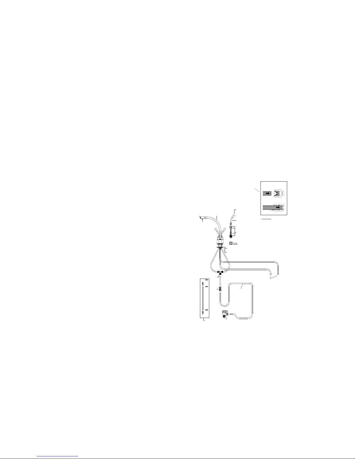
Spare Parts
For out-of-warranty maintenance and repairs, we recommend you em pl oy
a Registered Plumber.
Before ordering spare parts, determine the correct reference number from
the exploded diagram. Quote this number, and where appropriate, th e
color of your faucet.
Limited Warranty
Congratulations on the purchase of a Franke
product. Franke is one of t he world’s largest
manufacturers of kitchen s ystems. Our
products are manufactured using the highest
degree of technology quality and design. As
a result we are proud to of fer the following
warranty.
Frank e Inc. Kitchen Systems Division,
warrants the quality of its w ater dispensing
systems to be free from manufacturing
defects for a period of five years from the
date of purchase.
This warranty applies only to the original
owner, providing the product has been
installed in accordance with our installation
instructions, used as recommended and in a
normal residential applicat ion. In the event of
a warranty claim, the owner will be required
to provide proof of purchase. This warranty
covers all components nec essary to restore
the product to good working condition.
Frank e reserves the right to inspect the
installation prior to the replacement of the
product or component part .
This warranty does not cover misuse or
abuse, accidental damage, scuffs or
scratches, abnormal usage, negligence or
damage caused by improper maintenance or
cleaning. Normal wear of parts is excluded
from w arranty. Damage caused by impurities
or acts beyond our control are not covered.
Any product or part which has been repaired
or altered in any manner outside of Franke’s
factory, unless previously authorized in
writing by Franke, will void warranty. Any
replacement excludes transportation and
any labor reinstallation costs. This
warranty does not allow recovery of
incidental or consequential damages such as
loss of use, delay, property damage or other
consequential damage, and Franke accepts
no liability for such damages.
The Franke warranty is limited to the above
condition and to the warranty period
specified herein and is exclusive. Franke
DISCL AIMS all other warranties, expressed
or implied, including the IMPLIED
WARRANTIES OF MERCHANTABILITY
AND/ OR FITNESS FOR A PARTICULAR
PURPOSE. This warranty gives you specific
legal rights which may vary from state to
state.
What you must do: The purchaser should
retain original proof of purchase. Failure to
do so may void this warranty.
WARNING: Do NOT use tools
or mod ify the Push Fit
Connections as this could
dam ag e the co nne cti on
re su lti ng in lea ks and
will void the warranty.
Diagram B
P
ush Fit Connections
Connections To
Heating Tank
*Cut to Length for
Franke Canister
Silicone Tube
Kit - 2-023
Spout & Shank
3-010* - LB2200 Model
3-011* - LB3200 Model
3-012* - LB4200 Model
Clamp Plate - 10115
Cold Valve & Seat Set - 2-015
Hot Valve & Seat Set - 2-014
Flow Straightener
10159
Lever Kit - 3-002*
End Cap - 10166*
Lever End
10170* - LB2200 Model
10171* - LB3200 Model
10172* - LB4200 Model
Cover
10167* - LB2200 Model
10168* - LB3200 Model
10169* - LB4200 Model
10321
10306
Backnut - 92022
10322
WARNING: Do NOT
Use Tools
*Where Indicated Specify Color
 Loading...