

Franke Little Butler LB1000 Installation And User Manual
Franke Little Butler
Spare Parts & Warranty
Franke Little Butler
Installation and User Guide
Hot Water Dispensing System
Model Series LB1000
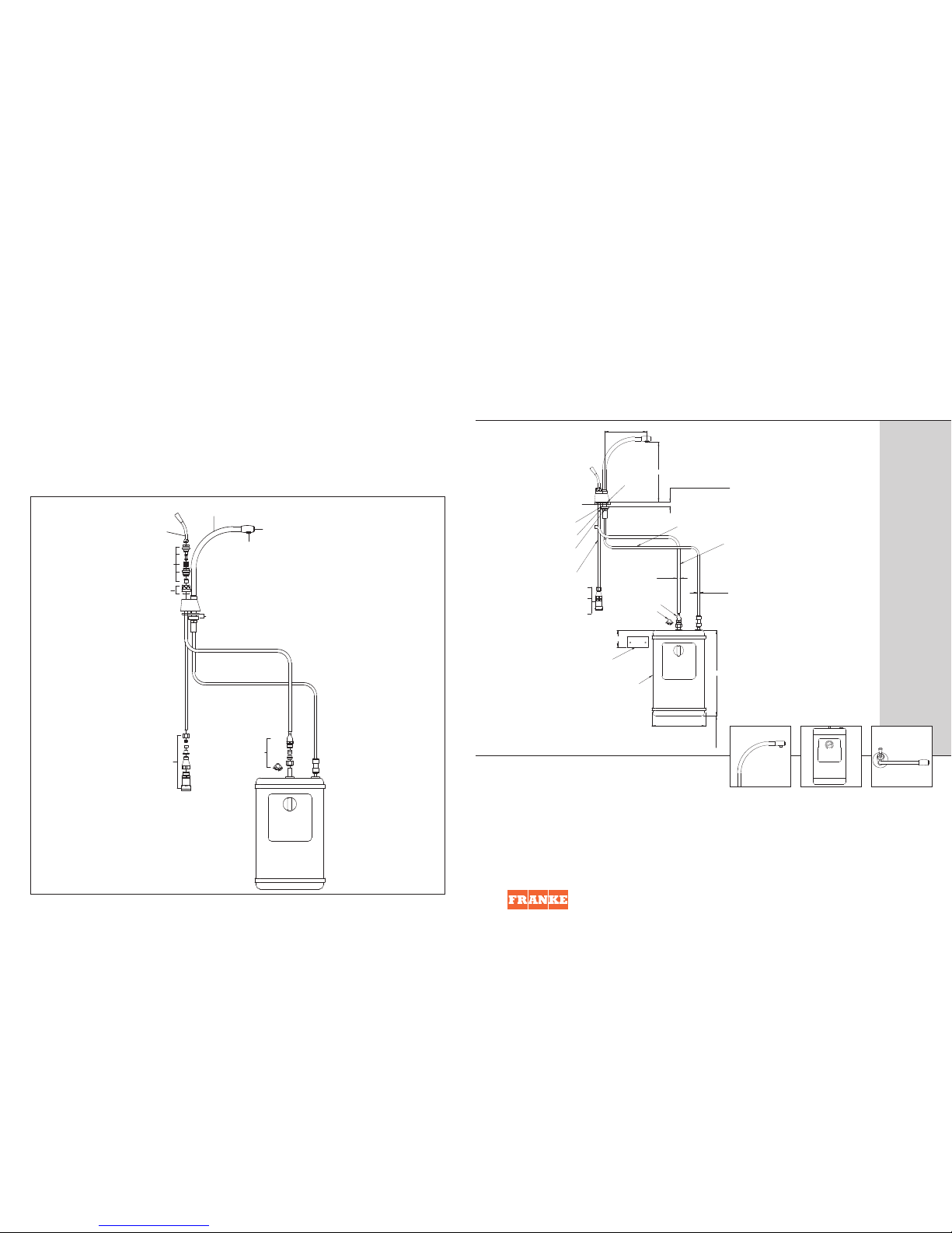
Spout & Shank
FR9106
Hot Lever Kit
FR9105
Hot Valve &
Seat Set - FR9103
Cover FR9101
Fixing Kit - FR9107
Flow Straightener
FR9180
End Cap
FR9108
FR9100
FR9104
S
pare Parts
For out-of-warranty maintenance and repairs, we recommend you employ a
Registered Plumber.
Before ordering spare parts, determine the correct reference number from the
exploded diagram. Quote this number, and where appropriate, the color ofyour
faucet
904993
Wall Mounting
Bracket
Heating
Tank
176
(Depth of Heating Tank 200)
(Provide Access for Drain Plug)
280
Hose Clip
Hose Connector
Ø
1
/4
"
Ø8
I
nlet Tube
305mm Long
Backnut
Lock Washer
Clamp Plate
Mesh Filter
2L/m Flow
C
ontroller
15mm-
1
/4
"
Compression
Fitting
5
0
'O' Ring Seal
195
138
Max Work Surface
T
hickness - 50
Tube to Heater 457mm Long
Norprene Tube
From Heater
4
57mm Long
50
Fr
ank
e
T
riflow
Unit
1, G
at
ew
a
y
XIII,
Ferry Lane, Rainham,
E
s
sex
RM13 9JY
Phone: +44 (0)1708 526361
F
ax: +44 (0)1708 550220
littlebutler@franke-triflow.co.uk
www.franke-triflow.co.uk
18" Long
C
lear Rubber Tube
From Heater
18" Long

Overview of the System Concept
This product dispenses near boiling water on demand for your
convenience. This product mayscald if used incorrectly and
is not recommended for use by children or the elderly. For
safety reasons, this hot water dispensing system features a
“non pressurized” heating tank. This meansthat the
incoming water is first routed through the valve in the
dispensing head, where line pressure feeding the system
terminates. When the valve is activated, water isdirected
down to feed the inlet at the top of the heater tank, displacing
heated water up through the spout. When the valve is off, the
tank is open to atmosphere (via the spout), making it
impossible for the tank to be subjected to stress from an
overheating condition.
Overview of Installation
There are two main components to the system, the dispensing
head and the heating tank. The dispensing head comes with
two 1/4” copper tubes and one flexible “Norprene” tube. The
short 305mm copper tube is connected to the incoming water
supply using the 15mm to 1/4” compression connector
containing a mesh filter and a 2 litre/min flow controller. The
longer (457mm) copper tube is connected to the inlet of the
tank. The flexible “Norprene” tube is connected to the outlet
of the tank using the hose connector.
Preparing for the Installation
As
w
ith an
y
s
ink
related device, it is much easier to mount the
dispensing head of this system onto the sinkbefore the sink
is mounted into the countertop. A mounting hole of 35mm
di
amet
er (s
t
andard sink ledge drilling) is required.
It is always recommended to take the components and locate
their optimum positions before starting the installation. This
particularly applies to the heating tank asit must be
positioned for the connections to the dispensing head, while
at the same time avoiding other mechanics under the sink.
Unlike most plumbing products, a hot water dispenser
includes an electrical system. The heating tankis supplied
with a grounded power cord and plug. A grounded nonswitchable outlet for this connection must be provided
bene
ath the s
ink.
IMPOR
T
ANT
Do not
plug in the unit until all water connections have been
m
a
de and the t
ank
is filled completely.
Making the Supply Provision
Pr
ovide a branch compression connection and a 15mm
supply tube. Flush the pipework before installing.
Mounting the Dispensing Head
The copper tubes are coiled for packing and must be carefully
straightened before installation. Position the ‘O’ring and feed
the tubes and shank through the hole in the sink ledge or
counter. Assemble the clamp plate locking washer and
backnut (hexagon to the top for thin sinks) fingertight. Turn
the dispensing head and the spout until the handle and spout
are in the required position for use and fully tighten the
backnut, this will lockthe spout in position.
Mounting the Heating Tank
The heating tank must be located on a backor side wall below
the sink, space will be needed underneath the tankfor access
to the drain plug. Determine the best position to enable the
tubing connections to be made and mark the position for the
mounting bracket (approximately 50mm below the top of the
tank). Attach the mounting bracketto the wall and hang the
tank in position.
IMPORTANT
During installation the tank should remain unplugged with
the thermostatic control in the “off” position. The tankmust
be filled with water before power is connected. A “dry start”
will void the warranty (see “Fill the System”). DO NOT
connect this product to the mains water supply, where the
supply pressure exceeds100psi (7 bar). If in any doubt,
p
l
e
ase ask your registered plumber to check the water
pressures. Failure to complywill invalidate the product
warranty.
IMPORTANT
Avoid kinking tubes during installation as the resulting
restrictions could reduce flow and cause malfunctioning of
the expansion chamber. Do not use pipe sealing compounds
on any connections. These can foul the internal mechanics
and may cause objectionable taste and odor. Plumbing
connections must comply with allsanitary, safety and
plumbing codes.
Fill the System - DO NOT PLUG IN YET
Turn on the water supply. Operate the lever on the dispensing
head and hold down until water flows from the end of the
spout. This will take a little while as the tank (capacity 2.3
litr
es) has to be filled. Check allconnections.
Franke Little Butler
Installation, Care and Maintenance
Franke Little Butler
Installation, Care and Maintenance
Plug in and Turn On
Plug into the electrical supply and turn temperature control
clockwise to a midway position on the shaded temperature
dial. Water in the tank will reach maximum temperature in
approximately 15-20 minutes. After this time the thermostat
may be safely increased up to the maximum setting. Gurgling
noises or perking sounds are normal during the initial heatup, and the product may purge some water.
Troubleshooting
Should your dispenser not work correctly, check the list below
before calling for service. The following thingsare not
covered by the warranty.
Water is not hot:
Check if electrical supply to heating tank is plugged in.
Turn temperature control knob clockwise as far as possible.
Test the temperature again after 15 minutes.
Check if fuse is blown or circuit breaker is open.
Hot water continuously drips or sputters from spout:
For safety reasons this Faucet may drip or splutter after use.
This venting prevents a build-up of pressure in the heating
tank. If
this becomes excessive;
T
urn the c
ontr
o
l
knob counter-clockwise to lower temperature.
Check the tubes connecting the faucet to the storage tank are
not
k
inked.
Chec
k
the c
ondition of
the me
sh filter in the 15mm to 1/4”
connector and clean or replace if necessary.
Water does not flow:
Check the water supply.
Check if supply tube is kinked.
Check if mesh filter in the 15mm to 1/4” connector is
clogged.
W
at
er boi
ls or vapor appears:
Lower temperature setting.
If
lo
w
ering of the thermostat setting does not stop the boiling,
u
np
lug the po
w
er s
up
ply cord and contact an authorized
service office.
Limited Warranty
Congratulations on the purchase of a Franke product.
Franke is one of the world’s largestmanufacturers of
kitchen systems. Our products are manufactured using the
highest degree of technology quality and design. As a
result we are proud to offer the following warranty.
Franke inc. Kitchen SystemsDivision, warrants the quality
of its water dispensing systems to be free from
manufacturing defects for a period of
five years from the
date of purchase.
This warranty applies only to the original owner, providing
the product has been installed in accordance with our
installation instructions, used as recommended and in a
normal residential application. In the event of a warranty
claim, the owner will be required to provide proof of
purchase. This warrantycovers all components necessary
to restore the product to good working condition. Franke
reserves the right to inspect the installation prior to the
replacement of the product or component part.
This warranty does not cover misuse or abuse, accidental
damage, scuffs or scratches, abnormalusage, negligence
or damage caused by improper maintenance or cleaning.
Normal wear of parts is excluded from warranty. Damage
c
au
sed b
y impurities or acts beyond our control are not
covered. Any product or part which has been repaired or
altered in any manner outside of Franke’s factory, unless
previously authorized in writing by Franke, will void
warranty.
Any replacement excludes transportation and
any labour re-installation costs. This warranty does not
allow recovery of incidental or consequentialdamages
such as loss of use, delay, property damage or other
consequential damage, and Franke accepts no liability for
such damages.
The Fr
ank
e w
arranty is limited to the above condition and
t
o the warranty period specified herein and is exclusive.
Franke
DISCLAIMS all other warranties, expressed or
imp
lied, including the
IMPLIED
WARRANTIES OF
MERCHANTABILITY AND/OR FITNESS FOR A PARTICULAR
PURPOSE.
This warranty gives you specific legal rights
which may vary from state to state.
Wh
at
y
ou mu
s
t
do:
The p
ur
c
h
a
ser shou
l
d pr
omptly
complete the product registration card and maildirectly
w
ithin tw
o w
eeks of the installation date. Failure to do so
m
a
y
v
oid thi
s
w
arranty.
 Loading...