

Franke FNE625XS, FNE925XS User Manual
Instructions for use and installation
Istruzioni per l’uso e l’installazione
Mode d’emploi et installation
Bedienungsanleitung und Installation
Kullan
ım ve montaj talimatları
Uživatelská P
øíruèka
Instrukcja obsługi i instalacji
GB
Cooker Hood
IT
Cappa
FR
Hotte de Cuisine
DE
Dunstabzugshaube
TR
Davlumbaz
CZ
Odsavač par
PL
Okap kuchenny
FNE 605 XS LED
FNE 905 XS LED
FNE 625 XS
FNE 925 XS
INDEX
SAFETY INFORMATION ......................................................................................................................................................... 4
CHARACTERISTICS ............................................................................................................................................................. 7
INSTALLATION ...................................................................................................................................................................... 8
USE ...................................................................................................................................................................................... 11
MAINTENANCE ................................................................................................................................................................... 12
EN
INDICE
INFORMAZIONI SULLA SICUREZZA .................................................................................................................................... 13
CARATTERISTICHE ............................................................................................................................................................ 16
INSTALLAZIONE ................................................................................................................................................................. 17
USO ...................................................................................................................................................................................... 20
MANUTENZIONE................................................................................................................................................................. 21
IT
SOMMAIRE
CONSIGNES DE SÉCURITÉ ................................................................................................................................................. 22
CARACTERISTIQUES ......................................................................................................................................................... 25
INSTALLATION .................................................................................................................................................................... 26
UTILISATION ....................................................................................................................................................................... 29
ENTRETIEN ......................................................................................................................................................................... 30
FR
INHALTSVERZEICHNIS
SICHERHEITSINFORMATIONEN ......................................................................................................................................... 31
CHARAKTERISTIKEN ......................................................................................................................................................... 34
MONTAGE ........................................................................................................................................................................... 35
BEDIENUNG ........................................................................................................................................................................ 38
WARTUNG ........................................................................................................................................................................... 39
DE
IÇERIKLER
GÜVENLİK HAKKINDA BİLGİLER ......................................................................................................................................... 40
ÖZELLIKLER ........................................................................................................................................................................ 43
MONTAJ ............................................................................................................................................................................... 44
KULLANIM ........................................................................................................................................................................... 47
BAKIM .................................................................................................................................................................................. 48
TR
OBSAH
INFORMACE O BEZPEČNOSTI ............................................................................................................................................ 49
HLAVNÍ PARAMETRY ......................................................................................................................................................... 52
INSTALACE ......................................................................................................................................................................... 53
POUŽITÍ ............................................................................................................................................................................... 56
ÚDRŽBA ............................................................................................................................................................................... 57
CZ
2
2

SPIS TREŚCI
INFORMACJE DOTYCZĄCE BEZPIECZEŃSTWA ................................................................................................................ 58
WŁAŚCIWOŚCI TECHNICZNE ........................................................................................................................................... 61
INSTALACJA ........................................................................................................................................................................ 62
UŻYTKOWANIE ................................................................................................................................................................... 65
KONSERWACJA.................................................................................................................................................................. 66
PL
3
3
EN
SAFETY INFORMATION
For your safety and correct operation of the appliance, read this manual
carefully before installation and use. Always keep these instructions
with the appliance even if you move or sell it. Users must fully know the
operation and safety features of the appliance.
The wire connection has to be done by specialized technician.
• The manufacturer will not be held liable for any damages resulting from
incorrect or improper installation.
• The minimum safety distance between the cooker top and the extractor
hood is 650 mm (some models can be installed at a lower height,
please refer to the paragraphs on working dimensions and installation).
• If the instructions for installation for the gas hob specify a greater
distance, this must be respected.
• Check that the mains voltage corresponds to that indicated on the
rating plate fixed to the inside of the hood.
• Means for disconnection must be incorporated in the fixed wiring in
accordance with the wiring rules.
• For Class I appliances, check that the domestic power supply
guarantees adequate earthing.
• Connect the extractor to the exhaust flue through a pipe of minimum
diameter 120 mm. The route of the flue must be as short as possible.
• Regulations concerning the discharge of air have to be fulfilled.
• Do not connect the extractor hood to exhaust ducts carrying
combustion fumes (boilers, fireplaces, etc.).
4
4
EN
•
If the extractor is used in conjunction with non-electrical appliances
(e.g. gas burning appliances), a sufficient degree of aeration must be
guaranteed in the room in order to prevent the backflow of exhaust gas.
When the cooker hood is used in conjunction with appliances supplied
with energy other than electric, the negative pressure in the room must
not exceed 0,04 mbar to prevent fumes being drawn back into the room
by the cooker hood.
• The air must not be discharged into a flue that is used for exhausting
fumes from appliances burning gas or other fuels.
• If the supply cord is damaged, it must be replaced from the manufac-
turer or its service agent.
• Connect the plug to a socket complying with current regulations, locat-
ed in an accessible place.
• With regards to the technical and safety measures to be adopted for
fume discharging it is important to closely follow the regulations provided by the local authorities.
WARNING: Before installing the Hood, remove the protective films.
• Use only screws and small parts in support of the hood.
WARNING: Failure to install the screws or fixing device in accordance
with these instructions may result in electrical hazards.
• Do not look directly at the light through optical devices (binoculars,
magnifying glasses…).
• Do not flambè under the range hood; risk of fire.
• This appliance can be used by children aged from 8 years and above
and persons with reduced physical, sensory or mental capabilities or
lack of experience and knowledge if they have been given supervision
or instruction concerning use of the appliance in a safe way and understand the hazards involved. Children shall not play with the appliance.
Cleaning and user maintenance shall not be made by children without
supervision.
• Children should be supervised to ensure that they do not play with the
appliance.
5
5
EN
•
The appliance is not to be used by persons (including children) with re-
duced physical, sensory or mental capabilities, or lack of experience
and knowledge, unless they have been given supervision or instruction.
Accessible parts may become hot when used with cooking appliances.
• Clean and/or replace the Filters after the specified time period (Fire
hazard). See paragraph Care and Cleaning.
• There shall be adequate ventilation of the room when the range hood is
used at the same time as appliances burning gas or other fuels (not
applicable to appliances that only discharge the air back into the room).
• The symbol
on the product or on its packaging indicates that this
product may not be treated as household waste. Instead it shall be
handed over to the applicable collection point for the recycling of electrical and electronic equipment. By ensuring this product is disposed of
correctly, you will help prevent potential negative consequences for the
environment and human health, which could otherwise be caused by
inappropriate waste handling of this product. For more detailed information about recycling of this product, please contact your local city office, your household waste disposal service or the shop where you purchased the product.
6
6
EN
CHARACTERISTICS
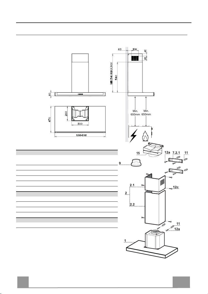
Dimensions
Components
Ref. Q.ty Product Components
1 1 Hood Body, complete with: Controls, Light, Blower,
2 1 Telescopic Chimney comprising:
2.1 1 Upper Section
2.2 1 Lower Section
9 1 Reducer Flange ø 150-120 mm
15 1 Air Outlet Connection
Ref. Q.ty Installation Components
7.2.1 2 Upper Chimney Section Fixing Brackets
11 6 Wall Plugs
12a 6 Screws 4,2 x 44,4
12c 6 Screws 2,9 x 9,5
Q.ty Documentation
1 Instruction Manual
Filters
7
7
EN
INSTALLATION
11
12a
320
X
116
1÷2
116
650 min.
7.2.1
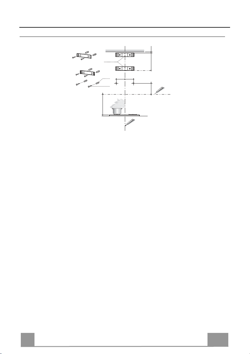
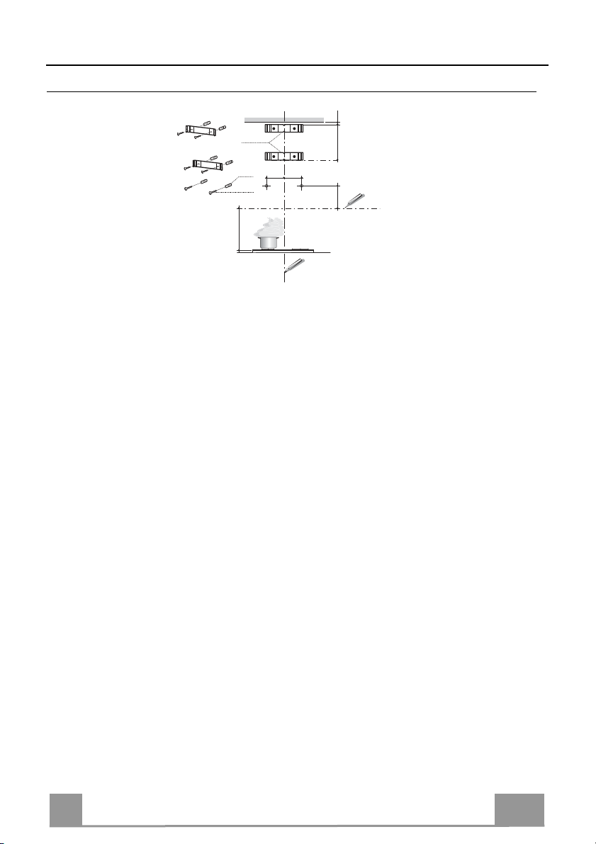
Wall drilling and bracket fixing
Wall marking:
• Draw a vertical line on the supporting wall up to the ceiling, or as high as practical, at the
centre of the area in which the hood will be installed.
• Draw a horizontal line at 650 mm above the hob. Place bracket 7.2.1 on the wall as shown
about 1-2 mm from the ceiling or upper limit aligning the centre (notch) with the vertical
reference line.
• Mark the wall at the centres of the holes in the bracket.
• Place bracket 7.2.1 on the wall as shown at X mm below the first bracket (X = height of the
upper
chimney section supplied), aligning the centre (notch) with the vertical line.
• Mark the wall at the centres of the holes in the bracket.
• Mark a reference point as indicated at 116 mm from the vertical reference line and 320 mm
above the horizontal reference line.
• Repeat this operation on the other side.
• Drill ø 8 mm holes at all the centre points marked.
• Insert the wall plugs 11 in the holes.
• Fix the brackets using the 12a (4,2 x 44,4) screws supplied.
• Insert the two screws 12a (4,2 x 44,4) supplied in the hood body fixing holes, leaving a gap
of 5-6 mm between the wall and the head of the screw.
8
8

EN
Mounting the hood body
12a
Vr
9
ø 120ø 150
• Before attaching the hood body, tighten the two screws Vr located on the hood body mounting points.
• Hook the hood body onto the screws 12a.
• Fully tighten the support screws 12a.
• Adjust the screws Vr to level the hood body.
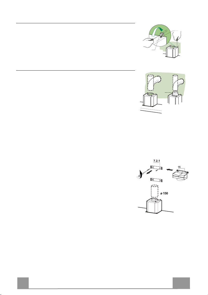
Connections
DUCTED VERSION AIR EXHAUST SYSTEM
When installing the ducted version, connect the hood to the
chimney using either a flexible or rigid pipe ø 150 or 120 mm,
the choice of which is left to the installer.
• To install a ø 120 mm air exhaust connection, insert the reducer flange 9 on the hood body outlet.
• Fix the pipe in position using sufficient pipe clamps (not supplied).
• Remove any activated charcoal filters.
AIR OUTLET – RECIRCULATION VERSION
• Unfasten the 2 screws fixing the upper bracket 7.2.1.
• Fasten the air outlet connector 15 in its place, using the 2
screws removed as above.
• Join the Connector 15 to the Hood canopy outlet using a rigid
or flexible pipe ø150 mm, selection of which is at the
discretion of the installation technician.
• Make sure that the Activated charcoal odour filter has been
fitted.
9
9

EN
1
ELECTRICAL CONNECTION
12b
• Connect the hood to the mains through a two-pole switch having a contact gap of at least 3 mm.
• Remove the grease filters (see paragraph Maintenance) being
sure that the connector of the feeding cable is correctly inserted
in the socket placed on the side of the fan.
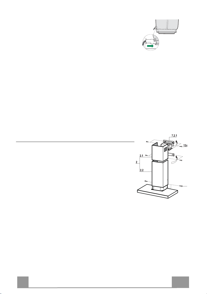
Flue assembly
Upper exhaust flue
• Slightly widen the two sides of the upper flue and hook them
behind the brackets 7.2.1, making sure that they are well seated.
• Secure the sides to the brackets by using the 4 screws 12c (2,9
x 9,5) supplied.
• Make sure that the outlet of the extensions pieces is aligned
with the chimney outlets.
Lower exhaust flue
• Slightly widen the two sides of the flue and hook them between the upper flue and the wall, making sure that they are
well seated.
• Fix the lower part laterally to the hood body by using the 2
screws 12c (2,9 x 9,5) supplied.
10
EN
1
USE
T2
T1
L
T3
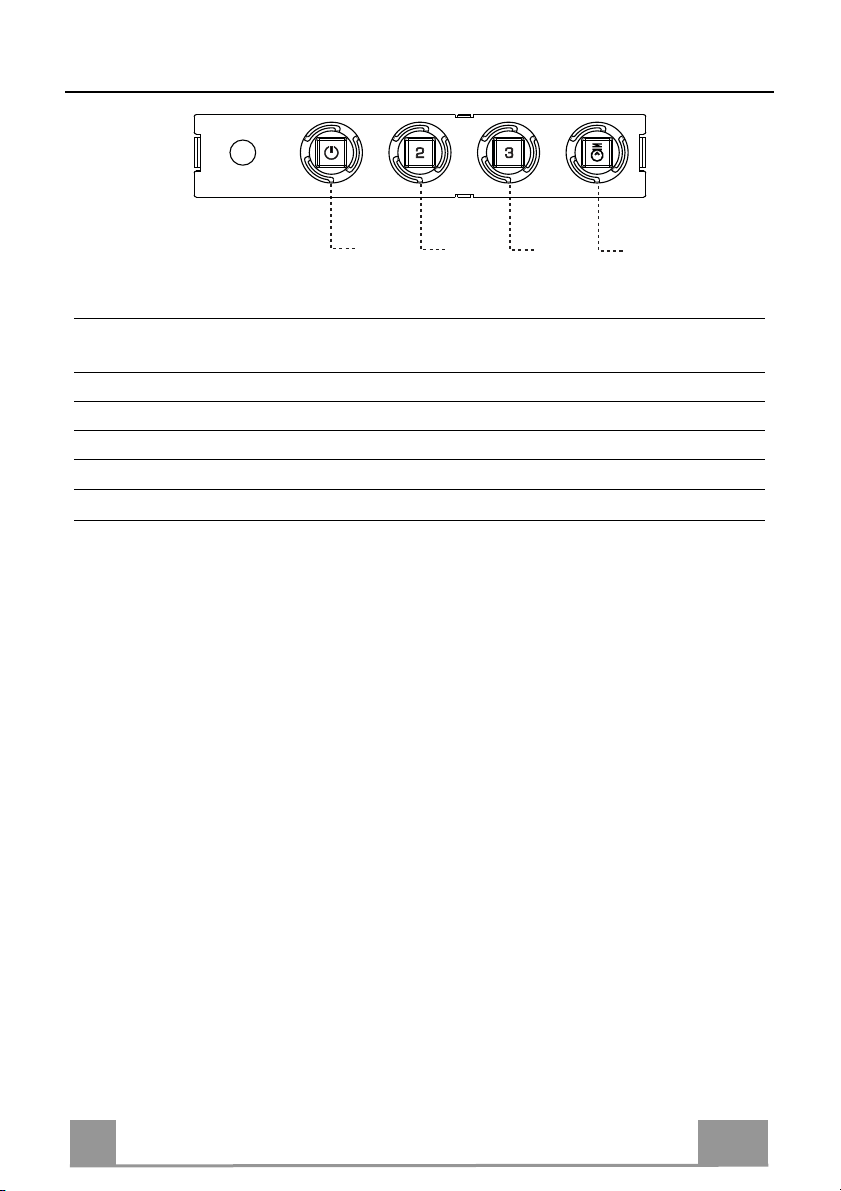
Control panel
BUTTON LED FUNCTIONS
T1 Speed On Turns the Motor on at Speed one.
Turns the Motor off.
T2 Speed On Turns the Motor on at Speed two.
T3 Speed Fixed When pressed briefly, turns the Motor on at Speed three.
L Light Turns the Lighting System on and off.
Warning: Button T1 turns the motor off, after first passing to speed one.
11
EN
1
MAINTENANCE
Grease filters
CLEANING METAL SELF- SUPPORTING GREASE FILTERS
• The filters must be cleaned every 2 months of operation, or
more frequently for particularly heavy usage, and can be
washed in a dishwasher.
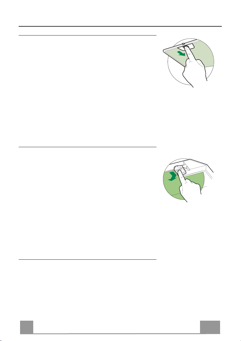
• Remove the filters one at a time by pushing them towards the
back of the group and pulling down at the same time.
• Wash the filters, taking care not to bend them. Allow them to
dry before refitting.
• When refitting the filters, make sure that the handle is visible
on the outside.
Activated charcoal filter (Recirculation version)
REPLACING THE ACTIVATED CHARCOAL FILTER
• The filter is not washable and cannot be regenerated, and must
be replaced approximately every 4 months of operation, or
more frequently for particularly heavy usage.
• Remove the metal grease filters.
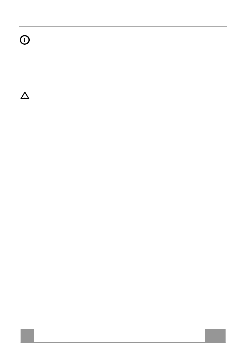
• Remove the saturated activated carbon filter by releasing the
fixing hooks.
• Fit the new filter by hooking it into its seating.
• Refit the metal grease filters.
Lighting unit
• For replacement contact technical support ("To purchase
contact technical support").
12
IT
1
INFORMAZIONI SULLA SICUREZZA
Per la propria sicurezza e per il corretto funzionamento dell’apparecchio,
si prega di leggere attentamente questo manuale prima dell’installazione e
della messa in funzione. Tenere queste istruzioni sempre insieme
all’apparecchio, anche in caso di cessione o trasferimento a terzi. È
importante che gli utilizzatori conoscano tutte le caratteristiche di
funzionamento e sicurezza dell’apparecchio.
Il collegamento dei cavi deve essere effettuato da un tecnico competente.
• Il fabbricante non potrà ritenersi responsabile per eventuali danni risultanti da
un’installazione o utilizzazione impropria.
• La distanza minima di sicurezza tra il piano cottura e la cappa aspirante è di
650 mm (alcuni modelli possono essere installati a un’altezza inferiore;
vedere il paragrafo relativo alle dimensioni di lavoro e all’installazione).
• Se le istruzioni di installazione del piano cottura a gas specificano una
distanza maggiore di quella sopra indicata, è necessario tenerne conto.
• Controllare che la tensione di rete corrisponda a quella indicata sulla targa
dati applicata all’interno della cappa.
• I dispositivi di sezionamento devono essere installati nell’impianto fisso in
conformità alle normative sui sistemi di cablaggio.
• Per gli apparecchi di Classe I, controllare che la rete di alimentazione
domestica disponga di un adeguato collegamento a massa.
• Collegare la cappa alla canna fumaria con un tubo di diametro minimo di 120
mm. Il percorso dei fumi deve essere il più corto possibile.
• Devono essere rispettate tutte le normative riguardanti lo scarico dell’aria.
• Non collegare la cappa aspirante ai condotti fumari che trasportano fumi di
combustione (per es. di caldaie, camini ecc.).
13
IT
1
• Se la cappa è utilizzata in combinazione con apparecchi non elettrici (per es.
apparecchi a gas), deve essere garantito un sufficiente grado di aerazione nel
locale per impedire il ritorno di flusso dei gas di scarico. Quando la cappa per
cucina è utilizzata in combinazione con apparecchi non alimentati dalla
corrente elettrica, la pressione negativa nel locale non deve superare 0,04
mbar per evitare che i fumi vengano riaspirati nel locale dalla cappa.
• L’aria non deve essere evacuata attraverso un condotto utilizzato per lo
scarico dei fumi da apparecchi di combustione alimentati a gas o altri
combustibili.
• Il cavo di alimentazione, se danneggiato, deve essere sostituito dal
fabbricante o da un tecnico del servizio assistenza.
• Collegare la spina ad una presa di tipo conforme alle normative vigenti e in
posizione accessibile.
• Relativamente alle misure tecniche e di sicurezza da adottare per lo scarico
dei fumi è importante attenersi scrupolosamente ai regolamenti stabiliti dalle
autorità locali.
AVVERTENZA: prima di installare la cappa, rimuovere le pellicole di
protezione.
• Usare solo viti e minuteria di tipo idoneo per la cappa.
AVVERTENZA: la mancata installazione delle viti o dei dispositivi di
fissaggio in conformità alle presenti istruzioni può comportare rischi di
scosse elettriche.
• Non osservare direttamente con strumenti ottici (binocolo, lente
d’ingrandimento….).
• Non cuocere al flambé sotto la cappa: si potrebbe sviluppare un incendio.
• Questo apparecchio può essere utilizzato da bambini di età non inferiore a 8
anni e da persone con ridotte capacità psico-fisico-sensoriali o con
esperienza e conoscenze insufficienti, purché attentamente sorvegliati e
istruiti su come utilizzare in modo sicuro l’apparecchio e sui pericoli che ciò
comporta. Assicurarsi che i bambini non giochino con l’apparecchio. Pulizia e
manutenzione da parte dell’utente non devono essere effettuate da bambini,
a meno che non siano sorvegliati.
• Sorvegliare i bambini, assicurandosi che non giochino con l’apparecchio.
14
IT
1
• L’apparecchio non deve essere utilizzato da persone (bambini compresi) con
ridotte capacità psico-fisico-sensoriali o con esperienza e conoscenze
insufficienti, a meno che non siano attentamente sorvegliate e istruite.
Le parti accessibili possono diventare molto calde durante l’uso degli
apparecchi di cottura.
• Pulire e/o sostituire i filtri dopo il periodo di tempo specificato (pericolo di
incendio). Vedere il paragrafo Manutenzione e pulizia.
• Deve essere presente un’adeguata ventilazione nel locale quando la cappa
è utilizzata contemporaneamente ad apparecchi che utilizzano gas o altri
combustibili (non applicabile ad apparecchi che scaricano unicamente l’aria
nel locale).
• Il simbolo sul prodotto o sulla sua confezione indica che il prodotto non
può essere smaltito come un normale rifiuto domestico. Il prodotto da
smaltire deve essere conferito presso un apposito centro di raccolta per il
riciclaggio dei componenti elettrici ed elettronici. Assicurandosi che questo
prodotto sia smaltito correttamente, si contribuirà a prevenire potenziali
conseguenze negative per l’ambiente e per la salute che potrebbero
altrimenti derivare dal suo smaltimento inadeguato. Per informazioni più
dettagliate sul riciclaggio di questo prodotto, contattare il Comune, il servizio
locale di smaltimento rifiuti oppure il negozio dove è stato acquistato il
prodotto.
15

IT
1
CARATTERISTICHE
Ingombro
Componenti
Rif. Q.tà Componenti di Prodotto
1 1 Corpo Cappa completo di: Comandi, Luce, Gruppo
2 1 Camino Telescopico formato da:
2.1 1 Camino Superiore
2.2 1 Camino Inferiore
9 1 Flangia di Riduzione ø 150-120 mm
15 1 Raccordo Uscita Aria
Rif. Q.tà Componenti di Installazione
7.2.1 2 Staffe Fissaggio Camino Superiore
11 6 Tasselli
12a 6 Viti 4,2 x 44,4
12c 6 Viti 2,9 x 9,5
Q.tà Documentazione
1 Libretto Istruzioni
Ventilatore, Filtri
16
IT
1
INSTALLAZIONE
11
12a
320
X
116
1÷2
116
650 min.
7.2.1
Foratura Parete e Fissaggio Staffe
Tracciare sulla Parete:
• una linea Verticale fino al soffitto o al limite superiore, al centro della zona prevista per il
montaggio della Cappa;
• una linea Orizzontale a: 650 mm min. sopra il Piano di Cottura.
• Appoggiare come indicato la Staffa 7.2.1 a 1-2 mm dal soffitto o dal limite superiore, allineando il suo centro (intagli) sulla linea Verticale di riferimento.
• Segnare i centri dei Fori della Staffa.
• Appoggiare come indicato la Staffa 7.2.1 a X mm sotto la prima staffa (X = altezza Camino
Superiore in dotazione), allineando il suo centro (intagli) sulla linea Verticale di riferimento.
• Segnare i centri dei Fori della Staffa.
• Segnare come indicato, un punto di riferimento a 116 mm dalla linea Verticale di riferimento, e 320 mm sopra la linea Orizzontale di riferimento.
• Ripetere questa operazione dalla parte opposta.
• Forare ø 8 mm i punti segnati.
• Inserire i tasselli 11 nei fori.
• Fissare le Staffe, utilizzando le Viti 12a (4,2 x 44,4 ) in dotazione.
• Avvitare 2 Viti 12a (4,2 x 44,4) in dotazione nei fori per il fissaggio del corpo Cappa, lasciando uno spazio di 5-6 mm fra la parete e la testa della vite.
17
IT
1
Montaggio Corpo Cappa
12a
Vr
9
ø 120ø 150
• Prima di agganciare il Corpo Cappa, serrare le 2 Viti Vr situate
sui punti di aggancio del Corpo Cappa.
• Agganciare il Corpo Cappa alle Viti 12a.
• Serrare definitivamente le Viti 12a di supporto.
• Agire sulle Viti Vr per livellare il Corpo Cappa.
Connessioni
USCITA ARIA VERSIONE ASPIRANTE
Per installazione in Versione Aspirante collegare la Cappa alla
tubazione di uscita per mezzo di un tubo rigido o flessibile di
ø150 o 120 mm, la cui scelta è lasciata all'installatore.
• Per collegamento con tubo ø120 mm, inserire la Flangia di riduzione 9 sull’Uscita del Corpo Cappa.
• Fissare il tubo con adeguate fascette stringitubo. Il materiale
occorrente non è in dotazione.
• Togliere eventuali Filtri Antiodore al Carbone attivo.
USCITA ARIA VERSIONE FILTRANTE
• Svitare le 2 Viti che fissano la Staffa Superiore 7.2.1.
• Avvitare al suo posto il Raccordo Uscita Aria 15 con le 2 viti
tolte in precedenza.
• Collegare il Raccordo 15 all’Uscita del Corpo Cappa per mezzo di un tubo rigido o flessibile di ø150 mm, la cui scelta è lasciata all'installatore.
• Assicurarsi della presenza del Filtro Antiodore al Carbone attivo.
18
IT
1
CONNESSIONE ELETTRICA
12b
• Collegare la Cappa all’Alimentazione di Rete interponendo un
Interruttore bipolare con apertura dei contatti di almeno 3 mm.
• Rimuovere i Filtri antigrasso (vedi par. “Manutenzione”) e assicurarsi che il connettore del Cavo di alimentazione sia correttamente inserito nella presa dell’Aspiratore
Montaggio Camino
Camino superiore
• Allargare leggermente le due falde laterali, agganciarle dietro
le Staffe 7.2.1 e richiuderle fino a battuta.
• Fissare lateralmente alle Staffe con 4 Viti 12c (2,9 x 9,5) in
dotazione.
• Assicurarsi che l’uscita delle Prolunghe Raccordo risulti in corrispondenza delle bocchette del Camino.
Camino inferiore
• Allargare leggermente le due falde laterali del Camino, agganciarle tra il Camino superiore e la parete e richiuderle fino a
battuta.
• Fissare lateralmente la parte inferiore al Corpo Cappa, con 2
Viti 12c (2,9 x 9,5) in dotazione.
19

IT
2
USO
T2
T1
L
T3
Quadro comandi
TASTO LED FUNZIONI
T1 Velocità Acceso Accende il Motore alla Prima velocità.
Spegne il Motore.
T2 Velocità Acceso Accende il Motore alla Seconda velocità.
T3 Velocità Fisso Premuto brevemente Accende il Motore alla Terza velocità.
L Luce Accende e spegne l’Impianto di Illuminazione.
Attenzione: Il tasto T1 spegne il motore passando sempre per la prima velocità.
20

IT
2
MANUTENZIONE
Filtri antigrasso
PULIZIA FILTRI ANTIGRASSO METALLICI AUTOPORTANTI
• Sono lavabili anche in lavastoviglie, e necessitano di essere
lavati ogni 2 mesi circa di utilizzo o più frequentemente, per un
uso particolarmente intenso.
• Togliere i Filtri uno alla volta, spingendoli verso la parte posteriore del gruppo e tirando contemporaneamente verso il basso.
• Lavare i Filtri evitando di piegarli, e lasciarli asciugare prima
di rimontarli.
• Rimontarli facendo attenzione a mantenere la maniglia verso la
parte visibile esterna.
Filtro antiodore (Versione Filtrante)
SOSTITUZIONE FILTRO ANTIODORE AL CARBONE ATTIVO
• Non è lavabile e non è rigenerabile, va sostituito almeno ogni 4
mesi o più frequentemente, per un uso particolarmente intenso.
• Togliere i Filtri antigrasso metallici.
• Rimuovere il Filtro antiodore al Carbone attivo saturo, agendo
sugli appositi agganci.
• Montare il nuovo Filtro agganciandolo nella sua sede.
• Rimontare i Filtri antigrasso metallici.
Illuminazione
• Per la sostituzione contattare l’Assistenza Tecnica ("Per
l'acquisto rivolgersi all'assistenza tecnica").
21
 Loading...