

FRANKE FKU908TCXS, FKU1008TCIXS, FKU1008ITCXS User Manual

Istruzioni per l’uso e l’installazione
Cappa
Instructions for use and installation
Cooker Hood
Mode d’emploi et installation
Hotte de Cuisine
Bedienungsanleitung und Einrichtung
Dunstabzugshaube
Kullanım ve montaj talimatları
Davlumbaz
Uživatelská Pøíruèka
Odsavač par
Handbok för installation, användning och underhăll
Spisfläkt
FKU 1008 I TC
IT
GB
FR
DE
TR
CZ
SE

2
2
INDICE
CONSIGLI E SUGGERIMENTI.............................................................................................................................................. 4
CARATTERISTICHE.............................................................................................................................................................. 5
INSTALLAZIONE ................................................................................................................................................................... 7
USO...................................................................................................................................................................................... 11
MANUTENZIONE ................................................................................................................................................................ 12
INDEX
RECOMMENDATIONS AND SUGGESTIONS ................................................................................................................... 14
CHARACTERISTICS ........................................................................................................................................................... 15
INSTALLATION.................................................................................................................................................................... 17
USE...................................................................................................................................................................................... 21
MAINTENANCE................................................................................................................................................................... 22
SOMMAIRE
CONSEILS ET SUGGESTIONS.......................................................................................................................................... 24
CARACTERISTIQUES ........................................................................................................................................................ 25
INSTALLATION.................................................................................................................................................................... 27
UTILISATION....................................................................................................................................................................... 31
ENTRETIEN......................................................................................................................................................................... 32
INHALTSVERZEICHNIS
EMPFEHLUNGEN UND HINWEISE................................................................................................................................... 34
CHARAKTERISTIKEN......................................................................................................................................................... 35
MONTAGE........................................................................................................................................................................... 37
BEDIENUNG........................................................................................................................................................................ 41
WARTUNG........................................................................................................................................................................... 42
IÇERIKLER
TAVSIYELER VE ÖNERILER.............................................................................................................................................. 44
ÖZELLIKLER ....................................................................................................................................................................... 45
MONTAJ............................................................................................................................................................................... 47
KULLANIM ........................................................................................................................................................................... 51
BAKIM .................................................................................................................................................................................. 52
OBSAH
RADY A DOPORUČENÍ...................................................................................................................................................... 54
HLAVNÍ PARAMETRY......................................................................................................................................................... 55
INSTALACE ......................................................................................................................................................................... 57
POUŽITÍ ............................................................................................................................................................................... 61
ÚDRŽBA............................................................................................................................................................................... 62
IT
EN
FR
DE
TR
CZ

3
3
INNEHÅLL
REKOMMENDATIONER OCH TIPS ................................................................................................................................... 64
EGENSKAPER .................................................................................................................................................................... 65
INSTALLATION.................................................................................................................................................................... 67
ANVÄNDING........................................................................................................................................................................ 71
UNDERHÅLL ....................................................................................................................................................................... 72
SE
IT
4
4
CONSIGLI E SUGGERIMENTI
Questo libretto di istruzioni per l'uso è previsto per più versioni dell' apparecchio.
É possibile che siano descritti singoli particolari della dotazione, che non riguardano il Vostro apparecchio.
INSTALLAZIONE
• Il produttore declina qualsiasi responsabilità per danni dovuti ad installazione non
corretta o non conforme alle regole dell’arte.
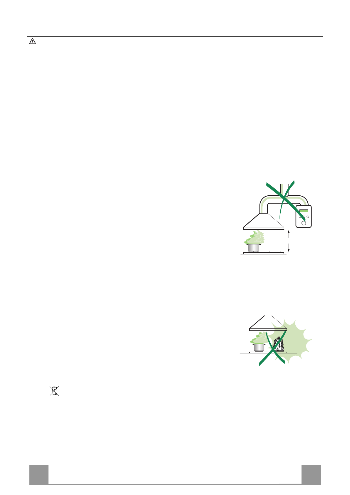
• La distanza minima di sicurezza tra il Piano di cottura e la Cappa deve essere di
650 mm, (alcuni modelli possono essere installati ad un’altezza inferiore, fare riferimento ai paragrafi ingombro e installazione).
• Verificare che la tensione di rete corrisponda a quella riportata nella targhetta
posta all’interno della Cappa.
• Per Apparecchi in Classe I
a
accertarsi che l’impianto elettrico domestico garanti-
sca un corretto scarico a terra.
• Collegare la Cappa all’uscita dell’aria aspirata con tubazione di diametro pari o
superiore a 120 mm. Il percorso della tubazione deve essere il più breve possibile.
• Non collegare la Cappa a condotti di scarico dei fumi prodotti da combustione
(caldaie, caminetti, ecc.).
• Nel caso in cui nella stanza vengano utilizzati sia la Cappa che apparecchi non
azionati da energia elettrica (ad esempio apparecchi utilizzatori di gas), si deve
provvedere ad una aerazione sufficiente dell’ambiente. Se la cucina ne fosse
sprovvista, praticare un’apertura che comunichi con l’esterno, per garantire il richiamo d’aria pulita.
USO
• La Cappa è stata progettata esclusivamente per uso domestico, per abbattere gli
odori della cucina.
• Non fare mai uso improprio della Cappa.
• Non lasciare fiamme libere a forte intensità sotto la Cappa in funzione.
• Regolare sempre le fiamme in modo da evitare una evidente fuoriuscita laterale
delle stesse rispetto al fondo delle pentole.
• Controllare le friggitrici durante l’uso: l’olio surriscaldato potrebbe infiammarsi.
• Non preparare alimenti flambè sotto la cappa da cucina; pericolo d'incendio.
• Questo apparecchio non deve essere utilizzato da persone (bambini inclusi) con
ridotte capacità psichiche, sensoriali o mentali, oppure da persone senza esperienza e conoscenza, a meno che non siano controllati o istruiti all’uso
dell’apparecchio da persone responsabili della loro sicurezza.
• I bambini devono essere supervisionati per assicurarsi che non giochino con
l’apparecchio.
MANUTENZIONE
• Prima di procedere a qualsiasi operazione di manutenzione, disinserire la Cappa
togliendo la spina elettrica o spegnendo l’interruttore generale.
• Effettuare una scrupolosa e tempestiva manutenzione dei Filtri secondo gli intervalli consigliati (Rischio di incendio).
• Per la pulizia delle superfici della Cappa è sufficiente utilizzare un panno umido e
detersivo liquido neutro.
Il simbolo sul prodotto o sulla confezione indica che il prodotto non deve essere considerato
come un normale rifiuto domestico, ma deve essere portato nel punto di raccolta appropriato per
il riciclaggio di apparecchiature elettriche ed elettroniche. Provvedendo a smaltire questo prodotto in modo appropriato, si contribuisce a evitare potenziali conseguenze negative per l’ambiente
e per la salute, che potrebbero derivare da uno smaltimento inadeguato del prodotto. Per informazioni più dettagliate sul riciclaggio di questo prodotto, contattare l’ufficio comunale, il servizio
locale di smaltimento rifiuti o il negozio in cui è stato acquistato il prodotto.
650 mm min.

IT
5
5
CARATTERISTICHE
Ingombro
Min.
650mm
Min.
650mm
IT
6
6
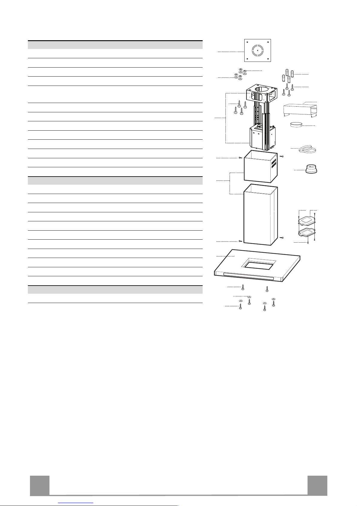
Componenti
Rif. Q.tà Componenti di Prodotto
1 1 Corpo Cappa completo di: Comandi, Luce, Filtri
2 1 Camino telescopico formato da:
2.1 1 Camino superiore
2.2 1 Camino inferiore
7.1 1 Traliccio telescopico completo di Aspiratore, formato
da:
7.1a 1 Traliccio superiore
7.1b 1 Traliccio inferiore
9 1 Flangia di riduzione ø 150-120 mm
10 1 Flangia ø 150
15 1 Raccordo Uscita Aria
24 1 Scatola connessioni
25 Fascette stringitubo (non incluse)
Rif. Q.tà Componenti di Installazione
11 4 Tasselli ø 10
12c 6 Viti 2,9 x 6,5
12e 2 Viti 2,9 x 9,5
12f 2 Viti M4 x 80
12g 4 Viti M6 x 80
12h 4 Viti 5,2 x 70
12q 4 Viti 3,5 x 9,5
21 1 Dima di foratura
22 8 Rondelle ø 6,4
23 4 Dadi M6
Q.tà Documentazione
1 Libretto Istruzioni
7.1a
7.1
22
23
12h
7.1b
2
2.1
2.2
12c
11
21
12g
1
15
12c
25
10
9
12c
24
12e
12f
12q
22

IT
7
7
INSTALLAZIONE
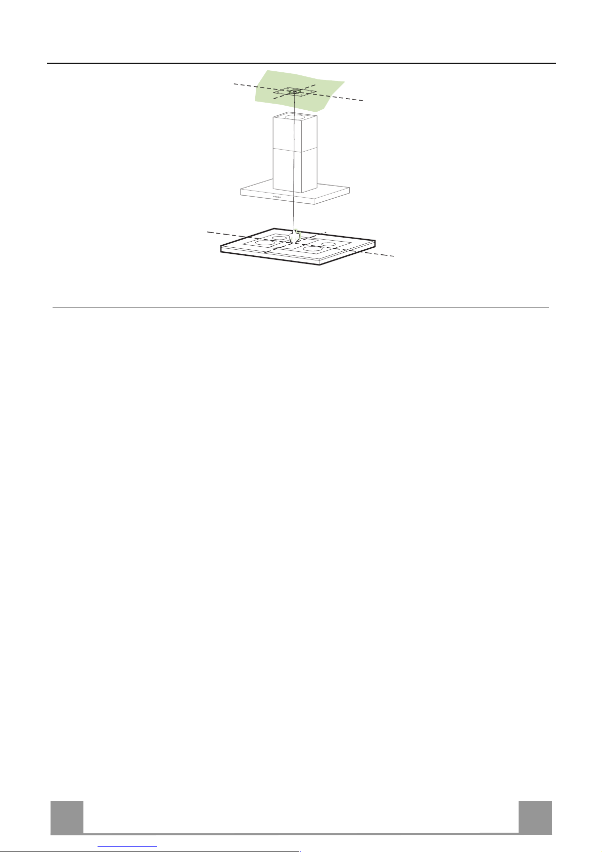
Foratura Soffitto/Mensola e Fissaggio Traliccio
FORATURA SOFFITTO/MENSOLA
• Con l’ausilio di un Filo a piombo riportare sul Soffitto/Mensola di supporto il centro del
Piano di Cottura.
• Appoggiare al Soffitto/Mensola la Dima di Foratura 21 in dotazione, facendo coincidere il
suo centro al centro proiettato e allineando gli assi della Dima agli assi del Piano di Cottura.
• Segnare i centri dei Fori della Dima.
• Forare i punti seguenti:
• Soffitto in Calcestruzzo massiccio: secondo Tasselli per Calcestruzzo impiegati.
• Soffitto in Laterizio a camera d’aria, con spessore resistente di 20 mm: ø 10 mm (inserire
subito i Tasselli 11 in dotazione).
• Soffitto in Travatura di Legno: secondo Viti per Legno impiegate.
• Mensola in Legno: ø 7 mm.
• Passaggio del Cavo elettrico di Alimentazione: ø 10 mm.
• Uscita Aria (Versione Aspirante): secondo diametro del collegamento alla Tubazione di
Evacuazione Esterna.
• Avvitare, incrociandole e lasciando 4-5 mm dal soffitto, due viti:
• per Calcestruzzo massiccio, Tasselli per Calcestruzzo, non in dotazione.
• per Laterizio a camera d’aria, con spessore resistente di 20 mm circa, Viti 12h, in dotazio-
ne.
• per Travatura di legno, Viti per legno, non in dotazione.
• per Mensola in Legno, viti 12g con Rondelle 22 e Dadi 23, in dotazione.
IT
8
8
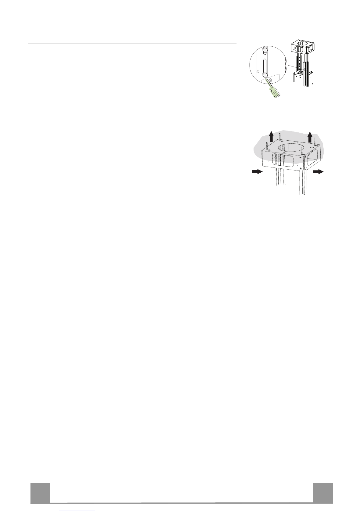
Fissaggio Traliccio
• Svitare le due viti che fissano il camino inferiore e sfilarlo dal
traliccio (dalla parte inferiore).
• Svitare le due viti che fissano il camino superiore e sfilarlo dal
traliccio (dalla parte superiore).
Nel caso in cui si voglia regolare l’altezza del traliccio procedere
come segue:
• Svitare le viti metriche che uniscono le due colonne, poste ai
lati del traliccio;
• Regolare l’altezza desiderata del traliccio e riavvitare le viti
precedentemente tolte;
• Inserire il camino superiore dall’ alto e lasciarlo libero sul traliccio;
• Sollevare il traliccio, incastrare le asole sulle viti e scorrere
fino a battuta;
• Stringere le due viti e avvitare le altre due in dotazione;
Prima di serrare definitivamente le viti è possibile effettuare delle
regolazioni spostando il traliccio, facendo attenzione che le viti
non escano dalla sede dell’asola di regolazione.
• Il fissaggio del Traliccio deve essere sicuro in relazione sia al
peso della Cappa sia alle sollecitazioni causate da occasionali
spinte laterali all’Apparecchio montato. A fissaggio avvenuto
verificare quindi che la base sia stabile anche se il Traliccio è
sollecitato a flessione.
• In tutti i casi in cui il Soffitto non fosse sufficientemente robusto sul punto di sospensione, l’Installatore dovrà provvedere a
irrobustirlo con opportune piastre e contropiastre ancorate a
parti strutturalmente resistenti.
2
2
1
1
IT
9
9
Connessioni
USCITA ARIA VERSIONE ASPIRANTE
Per installazione in Versione Aspirante collegare la Cappa alla
tubazione di uscita per mezzo di un tubo rigido o flessibile di
ø150 o 120 mm, la cui scelta è lasciata all'installatore.
• Per collegamento con tubo ø120 mm, inserire la Flangia di riduzione 9 sull’Uscita del Corpo Cappa.
• Fissare il tubo con adeguate fascette stringitubo. Il materiale
occorrente non è in dotazione.
• Togliere eventuali Filtri Antiodore al Carbone attivo.
9
ø 150
ø 120
25
25
Uscita aria Versione Filtrante
• Fissare il Raccordo 15 al traliccio utilizzando le 4 Viti in dotazione.
• Incastrare la flangia 10 nell’apposito foro inferiore del Raccordo 15.
• Collegare l’uscita aria della cappa con la flangia posta sotto al
raccordo per mezzo di un tubo rigido o flessibile ø 150mm , la
cui scelta è lasciata all’installatore
15
10

IT
1
10
Montaggio Camino e Fissaggio Corpo Cappa
• Posizionare il Camino superiore e fissare nella parte superiore
al Traliccio con 2 Viti 12c (2,9 x 6,5) in dotazione.
• Analogamente posizionare il Camino inferiore e fissare nella
parte inferiore al Traliccio con 2 Viti 12c (2,9 x 6,5) in dotazione.
Prima di fissare il Corpo Cappa al Traliccio:
• Avvitare per metà le 2 Viti 12f sulla parte inferiore del traliccio
in posizione laterale in corrispondenza dei 2 fori predisposti.
• Togliere i Filtri antigrasso dal Corpo Cappa;
• Togliere eventuali Filtri Antiodore al Carbone attivo.
• Sollevare il Corpo Cappa e incastrare le Viti 12f sulle asole
(rif.A) fino a battuta.
• Fissare da sotto con 4 Viti 12q e 4 Rondelle 22 in dotazione il
Corpo Cappa al Traliccio predisposto (rif.B) e serrare definitivamente tutte le Viti.
12c
12c
22
12f
12q
A
B
Connessione elettrica
• Collegare la Cappa all’Alimentazione di Rete interponendo un
Interruttore bipolare con apertura dei contatti di almeno 3 mm.
• Rimuovere i Filtri antigrasso (vedi par. “Manutenzione”) e assicurarsi che il connettore del Cavo di alimentazione sia correttamente inserito nella presa dell’Aspiratore
• Collegare il Connettore dei Comandi Cmd.
• Collegare il Connettore dei Faretti Lux.
• Riporre entrambi i Connettori nella Scatola di protezione 24
chiudendola con 2 Viti 12e(2,9 x 9,5) in dotazione.
• Fissare la Scatola di protezione al Corpo Cappa con 2 Viti 12c
(2,9 x 6,5) in dotazione.
• Per la Versione Filtrante montare il Filtro Antiodore al Carbone attivo.
• Rimontare i Filtri Antigrasso.
24
12e
Cmd
12c
Lux
IT
1
11
USO
Quadro comandi
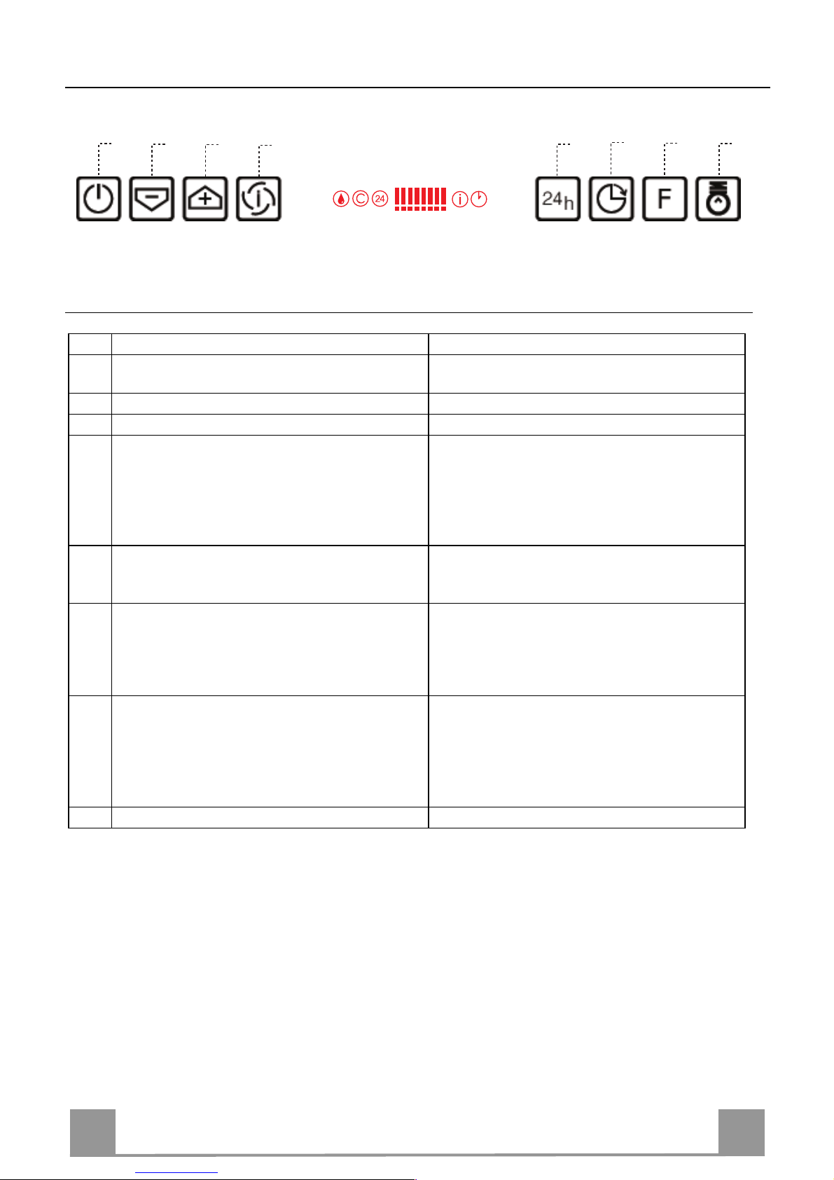
Tasto Funzione Display
A Accende e spegne il motore di aspirazione
all’ultima velocità utilizzata.
Visualizza la velocità impostata.
B Decrementa la velocità di esercizio. Diminuiscono i segmenti accesi.
C Incrementa la velocità di esercizio. Aumentano i segmenti accesi.
D Attiva la velocità intensiva da qualsiasi velo-
cità anche da motore spento, tale velocità è
temporizzata a 10 minuti, al termine del tempo
il sistema ritorna alla velocità precedentemente
impostata. Adatta a fronteggiare le massime
emissioni di fumi di cottura.
Lampeggia I e i segmenti sul Display sono tutti
accesi.
Si disattiva premendo il Tasto.
E Attiva il motore ad una velocità che consente
un’aspirazione di 100 m
3
/h per 10 minuti ogni
ora, terminati il motore si ferma.
Visualizza 24 e i segmenti sul Display da tutti
accesi si spengono uno alla volta ciclicamente.
Si disattiva premendo il Tasto.
F Attiva lo spegnimento automatico ritardato di
30’. Adatto per completare l’eliminazione di
odori residui. Attivabile da qualsiasi posizione,
si disattiva premendo il tasto o spegnendo il
motore.
Visualizza il simbolo di un Orologio che lampeggia.
Si disattiva premendo il Tasto.
G Effettua il Reset dell’allarme saturazione Filtri
premendo il Tasto per circa 2 Secondi.
Dopo 100 ore di Funzionamento Visualizza il
simbolo Goccia per segnalare la saturazione
dei Filtri Metallici.
Dopo 200 ore di Funzionamento Visualizza C
per segnalare la saturazione dei Filtri al Carbone Attivo.
H Accende e spegne l’impianto di illuminazione.
Comando Blocco Tastiera: è possibile bloccare la tastiera, ad esempio per effettuare la pulizia
del Vetro, quando la Cappa ha il Motore e le Luci spente.
Premendo per circa 5 Secondi il tasto F (Delay) si può abilitare o disabilitare il Blocco Tastiera
che è sempre confermato con un Beep e un’animazione sulla barra motore del display.
B
A
D
C
E
H
G
F

IT
1
12
MANUTENZIONE
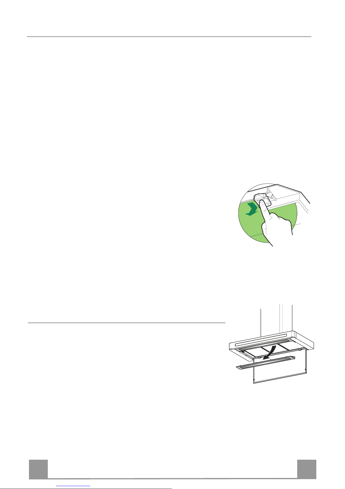
Pulizia dei Comfort Panel
• Aprire il Comfort Panel tirandolo.
• Sganciare il cavo di sicurezza aprendo il moschettone.
• Sganciare il pannello dal corpo cappa facendo scorrere
l’apposita leva del perno di fissaggio.
• Il comfort panel non va assolutamente lavato in lavastoviglie.
• Pulirlo esternamente con un panno umido e detersivo liquido
neutro.
• Pulirlo anche internamente utilizzando un panno umido e detergente neutro; non utilizzare panni o spugne bagnate, né getti
d’acqua; non utilizzare sostanze abrasive.
• Ad operazione ultimata riagganciare il pannello e il moschettone al corpo cappa e richiuderlo.
11
22
Filtri antigrasso metallici
Sono lavabili anche in lavastoviglie, e necessitano di essere lavati
quando sul display appare il simbolo Goccia o almeno ogni 2
mesi circa di utilizzo o più frequentemente, per un uso particolarmente intenso.
Reset del segnale di allarme
• Premere il tasto G per almeno 2 Secondi.
Pulizia Filtri
• Aprire il comfort panel.
• Togliere i Filtri uno alla volta, spingendoli verso la parte posteriore del gruppo e tirando contemporaneamente verso il basso.
• Lavare i Filtri evitando di piegarli, e lasciarli asciugare prima
di rimontarli. (Un’eventuale cambiamento del colore della superficie del filtro, che potrebbe verificarsi nel tempo, non pregiudica assolutamente l’efficienza dello stesso.)
• Rimontarli facendo attenzione a mantenere la maniglia verso la
parte visibile esterna.
• Richiudere il comfort panel.
IT
1
13
Filtri antiodore al Carbone attivo (Versione Filtrante)
Non è lavabile e non è rigenerabile, va sostituito quando sul display appare il simbolo C o almeno ogni 4 mesi. La segnalazione di Allarme va preventivamente attivata.
Attivazione del segnale di allarme
• Nelle Cappe in Versione Filtrante, la segnalazione di Allarme saturazione Filtri va attivata al
momento dell’installazione o successivamente.
• Spegnere le Luci e il Motore di aspirazione.
• Premere il tasto E per circa 5 Sec. fino all’accensione degli ultimi due segmenti e di tutta la
linea puntinata della barra Motore sul Display.
• Rilasciare il tasto E, l’icona “Orologio” inizia a lampeggiare.
• Entro 3 secondi premere il Tasto D per abilitazione / disabilitazione Filtri C.A.
• Accensione del simbolo C Allarme saturazione Filtro C.A. ATTIVATO
• Spegnimento del simbolo C Allarme saturazione Filtro C.A. DISATTIVATO
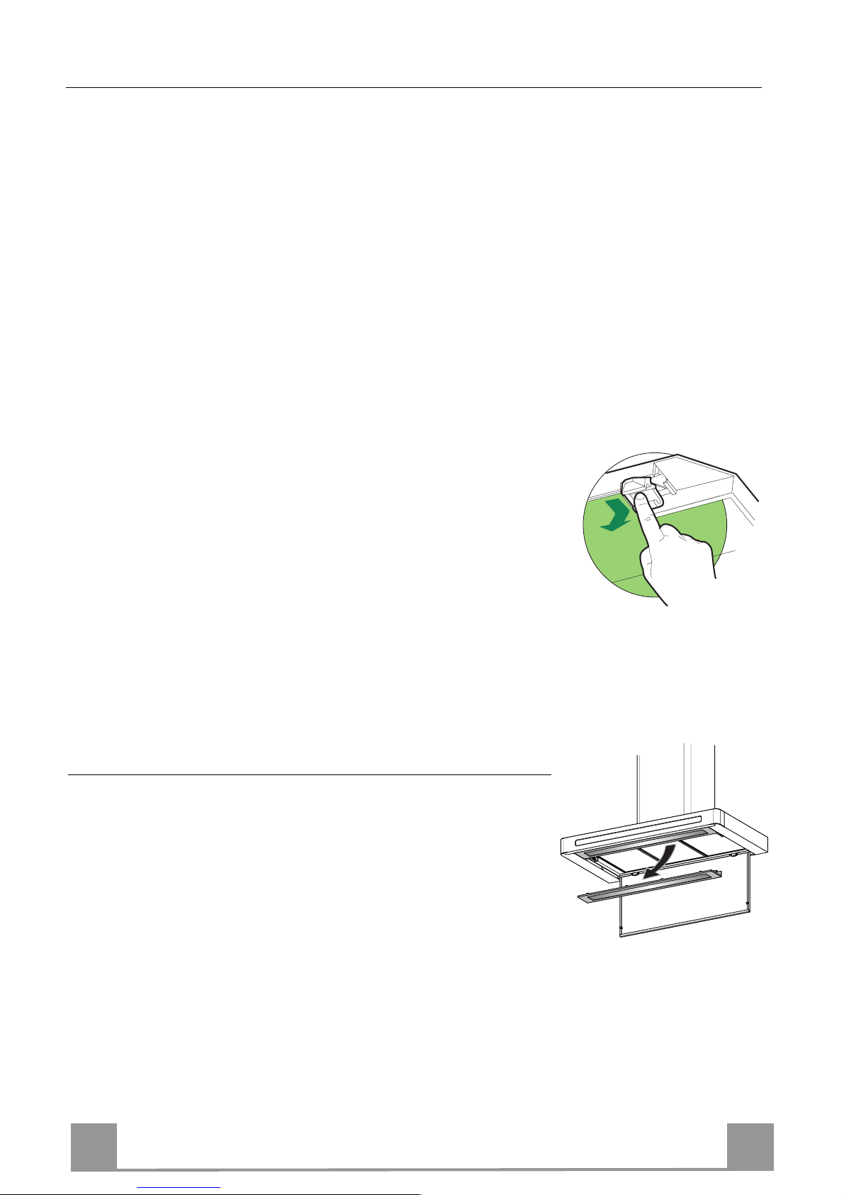
SOSTITUZIONE FILTRO ANTIODORE AL CARBONE ATTIVO
Reset del segnale di allarme
• Spegnere le Luci e il Motore di aspirazione.
• Premere il tasto G per almeno 2 Secondi.
Sostituzione Filtro
• Aprire il comfort panel.
• Togliere i Filtri antigrasso metallici.
• Rimuovere il Filtro antiodore al Carbone attivo saturo, come
indicato in figura.
• Montare il nuovo Filtro agganciandolo nella sua sede.
• Rimontare i Filtri antigrasso metallici.
Illuminazione
SOSTITUZIONE LAMPADA
Lampada Neon 16 W
• Aprire il comfort panel.
• Rimuovere la protezione neon svitando le viti e sfilandola
dall’apposita sede.
• Sostituire il Neon o lo Starter, facendo attenzione che i nuovi
abbiano le stesse caratteristiche dei vecchi.
• Riposizionare la protezione neon.
• Richiudere il comfort panel.

EN
1
14
RECOMMENDATIONS AND SUGGESTIONS
The Instructions for Use apply to several versions of this appliance. Accord-
ingly, you may find descriptions of individual features that do not apply to
your specific appliance.
INSTALLATION
• The manufacturer will not be held liable for any damages resulting from incorrect or improper installation.
• The minimum safety distance between the cooker top and the extractor
hood is 650 mm (some models can be installed at a lower height, please refer to the paragraphs on working dimensions and installation).
• Check that the mains voltage corresponds to that indicated on the rating
plate fixed to the inside of the hood.
• For Class I appliances, check that the domestic power supply guarantees
adequate earthing.
Connect the extractor to the exhaust flue through a pipe of minimum diame-
ter 120 mm. The route of the flue must be as short as possible.
• Do not connect the extractor hood to exhaust ducts carrying combustion
fumes (boilers, fireplaces, etc.).
• If the extractor is used in conjunction with non-electrical appliances (e.g. gas
burning appliances), a sufficient degree of aeration must be guaranteed in
the room in order to prevent the backflow of exhaust gas. The kitchen must
have an opening communicating directly with the open air in order to guarantee the entry of clean air.
USE
• The extractor hood has been designed exclusively for domestic use to eliminate kitchen smells.
• Never use the hood for purposes other than for which it has been designed.
• Never leave high naked flames under the hood when it is in operation.
• Adjust the flame intensity to direct it onto the bottom of the pan only, making
sure that it does not engulf the sides.
• Deep fat fryers must be continuously monitored during use: overheated oil
can burst into flames.
• Do not flambè under the range hood; risk of fire
• This appliance is not intended for use by persons (including children) with
reduced physical, sensory or mental capabilities, or lack of experience and
knowledge, unless they have been given supervision or instruction concerning use of the appliance by a person responsible for their safety.
• Children should be supervised to ensure that they do not play with the appliance.
MAINTENANCE
• Switch off or unplug the appliance from the mains supply before carrying out
any maintenance work.
• Clean and/or replace the Filters after the specified time period (Fire hazard).
• Clean the hood using a damp cloth and a neutral liquid detergent.
The symbol on the product or on its packaging indicates that this product may not be treated
as household waste. Instead it shall be handed over to the applicable collection point for the
recycling of electrical and electronic equipment. By ensuring this product is disposed of correctly,
you will help prevent potential negative consequences for the environment and human health,
which could otherwise be caused by inappropriate waste handling of this product. For more
detailed information about recycling of this product, please contact your local city office, your
household waste disposal service or the shop where you purchased the product.
650 mm min.
EN
1
15
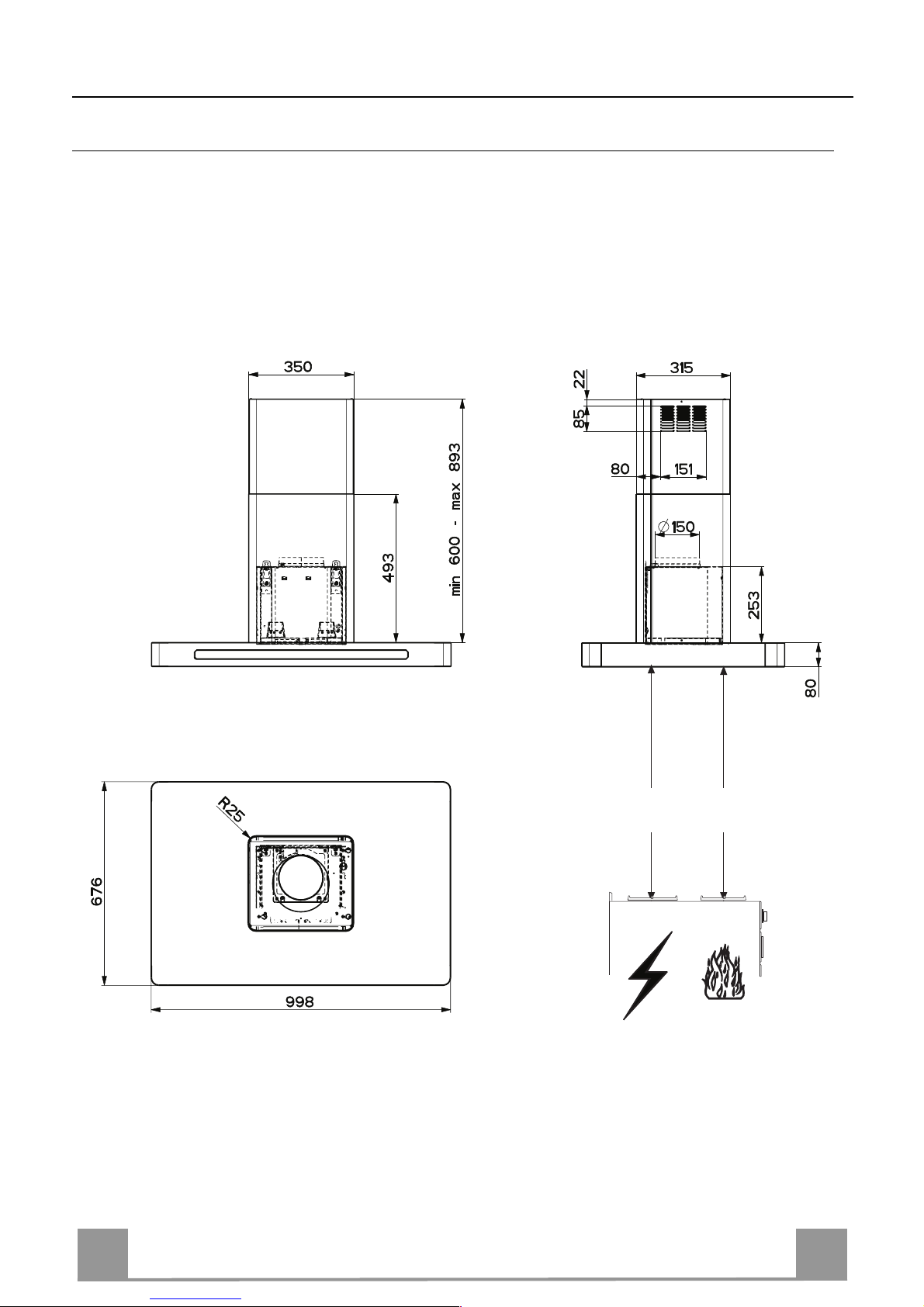
CHARACTERISTICS
Dimensions
Min.
650mm
Min.
650mm
EN
1
16
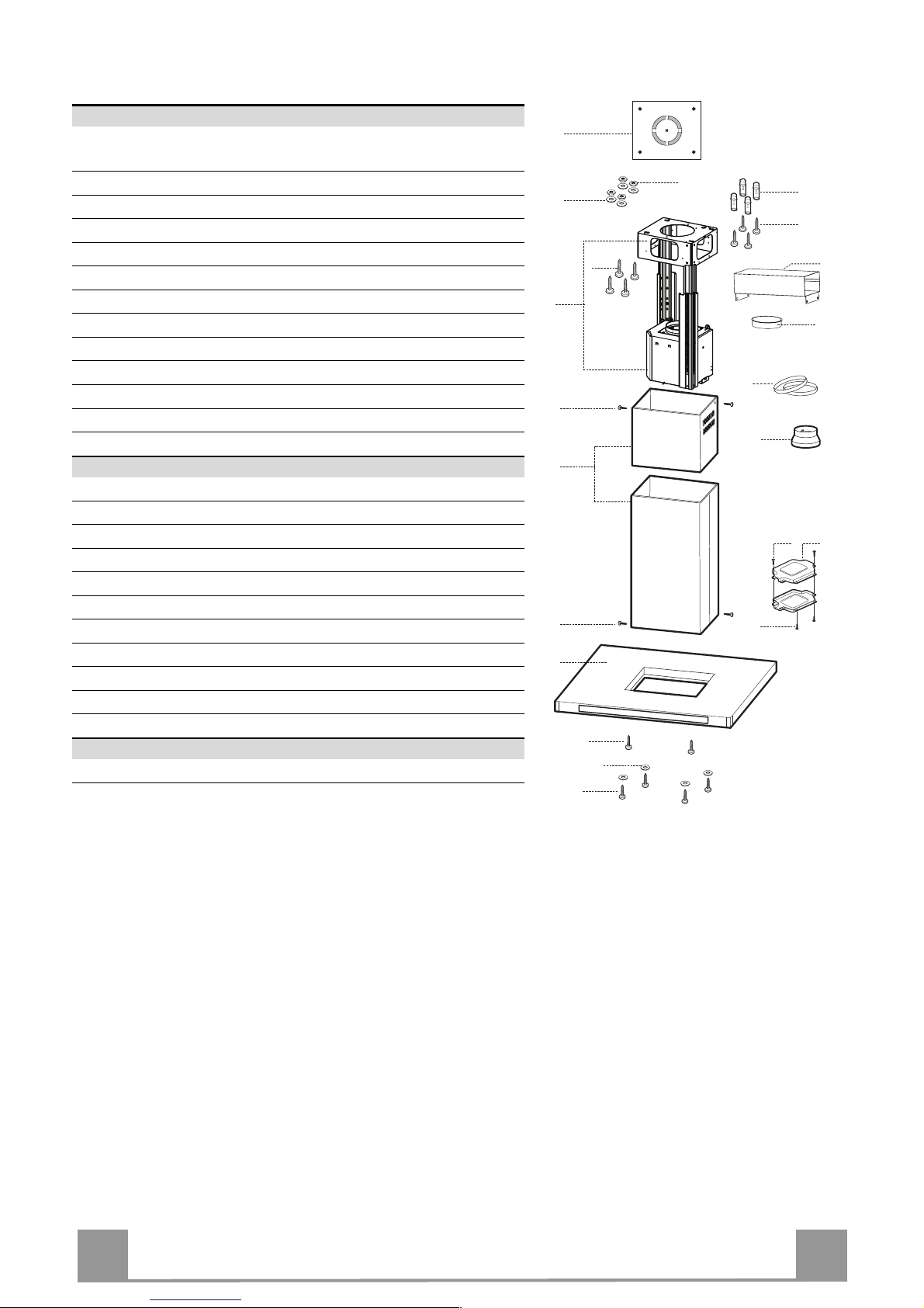
Components
Ref. Q.ty Product Components
1 1 Hood Body, complete with: Controls, Light, Blower,
Filters
2 1 Telescopic Chimney comprising:
2.1 1 Upper Section
2.2 1 Lower Section
7.1 1 Telescopic frame complete with extractor, consisting of:
7.1a 1 Upper frame
7.1b 1 Lower frame
9 1 Reducer Flange ø 150-120 mm
10 1 Flange ø 150
15 1 Air Outlet Connection
24 1 Junction box
25 Pipe clamps (not included)
Ref. Q.ty Installation Components
11 4 Wall Plugs ø 10
12c 6 Screws 2,9 x 6,5
12e 2 Screws 2,9 x 9,5
12f 2 Screws M4 x 80
12g 4 Screws M6 x 80
12h 4 Screws 5,2 x 70
12q 4 Screws 3,5 x 9,5
21 1 Drilling template
22 8 6.4 mm int. dia washers
23 4 M6 nuts
Q.ty Documentation
1 Instruction Manual
7.1a
7.1
22
23
12h
7.1b
2
2.1
2.2
12c
11
21
12g
1
15
12c
25
10
9
12c
24
12e
12f
12q
22
EN
1
17
INSTALLATION
Drilling the Ceiling/shelf and fixing the frame
DRILLING THE CEILING/SHELF
• Use a plumb line to mark the centre of the hob on the ceiling/support shelf.
• Place the drilling template 21 provided on the ceiling/support shelf, making sure that the
template is in the correct position by lining up the axes of the template with those of the hob.
• Mark the centres of the holes in the template.
• Drill the holes at the points marked:
• For concrete ceilings, drill for plugs appropriate to the screw size.
• For hollow brick ceilings with wall thickness of 20 mm: drill ø 10 mm(immediately insert
the Dowels 11 supplied).
• For wooden beam ceilings, drill according to the wood screws used.
• For wooden shelf, drill ø 7 mm.
• For the power supply cable feed, drill ø 10 mm.
• For the air outlet (Ducted Version), drill according to the diameter of the external air ex-
haust duct connection.
• Insert two screws of the following type, crossing them and leaving 4-5 mm from the ceiling:
• For concrete ceilings, use the appropriate plugs for the screw size (not provided).
• for Cavity ceiling with inner space, with wall thickness of approx. 20 mm, Screws 12h,
supplied.
• For wooden beam ceilings, use 4 wood screws (not provided).
• For wooden shelf, use 4 screws 12g with washers 22 and nuts 23, provided.

EN
1
18
Fixing the frame
• Loosen the two screws fastening the lower chimney and remove this from the lower frame.
• Loosen the two screws fastening the upper chimney and remove this from the upper frame.
If you wish to adjust the height of the frame, proceed as follows:
• Unfasten the metric screws joining the two columns, located at
the sides of the frame.
• Adjust the frame to the height required, then refit all the screws
removed as above.
• Insert the upper chimney stack from above, and leave it running free on the frame.
• Lift up the frame, fit the frame slots onto the screws up to the
slot end positions.
• Tighten the two screws and fasten the other two screws provided with the hood.
Before tightening the screws completely it is possible to adjust
the frame by turning it. Make sure that the screws do not come
out of their seats in the slotted holes.
• The frame mountings must be secure to withstand the weight
of the hood and any stresses caused by the occasional side
thrust applied to the device.
On completion, check that the base is stable, even if the frame
is subjected to bending.
• In all cases where the ceiling is not strong enough at the suspension point, the installer must provide strengthening using
suitable plates and backing pieces anchored to the structurally
sound parts.
2
2
1
1

EN
1
19
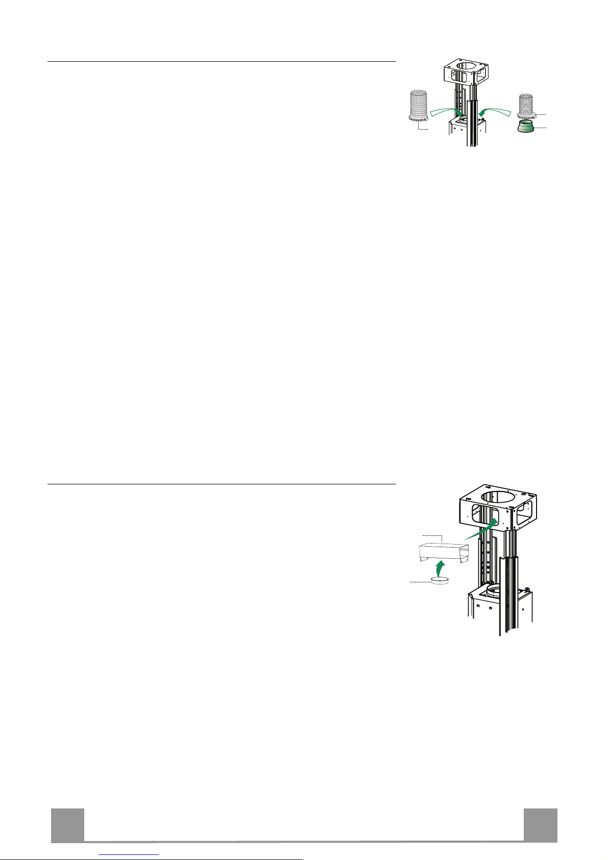
Connections
DUCTED VERSION AIR EXHAUST SYSTEM
When installing the ducted version, connect the hood to the
chimney using either a flexible or rigid pipe ø 150 or 120 mm,
the choice of which is left to the installer.
• To install a ø 120 mm air exhaust connection, insert the reducer flange 9 on the hood body outlet.
• Fix the pipe in position using sufficient pipe clamps (not supplied).
• Remove any activated charcoal filters.
9
ø 150
ø 120
25
25
Recirculation version air outlet
• Fix the connection 15 to the frame using the 4 screws provided.
• Fix the flange 10 to the lower opening of the connection 15.
• Connect the hood air outlet to the flange in the lower part of
the junction using a rigid or flexible ø 150 tube (by installer’s
choice).
15
10
EN
2
20
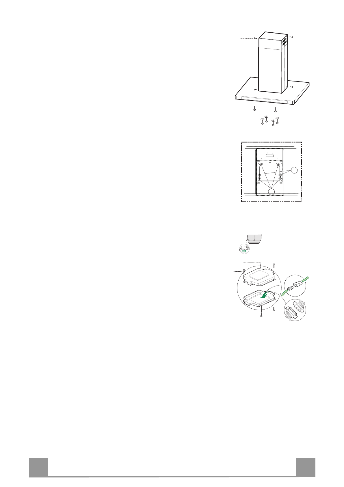
Flue assembly - Mounting the hood body
• Position the upper chimney section and fix the upper part to the
frame using the 2 screws 12c (2,9 x 6,5) provided.
• Similarly, position the lower chimney section and fix the
lower part to the frame using the 2 screws 12c (2,9 x 6,5) provided.
Before fixing the hood canopy to the frame:
• Screw the 2 screws 12f half way into the holes provided in the
sides of the bottom of the frame.
• Remove the grease filters from the hood canopy.
• Remove any activated charcoal filters.
• Lift the hood canopy and engage the screws 12f in the slots (A)
as far as they will go.
• Working from below, fix the hood canopy to the frame (B),
using the 4 screws 12q and 4 washers 22 provided, then tighten
all the screws securely.
12c
12c
22
12f
12q
A
B
ELECTRICAL CONNECTION
• Connect the hood to the mains through a two-pole switch having a contact gap of at least 3 mm.
• Remove the grease filters (see paragraph Maintenance) being
sure that the connector of the feeding cable is correctly inserted
in the socket placed on the side of the fan.
• Connect the control connector Cmd.
• Connect the lights connector Lux.
• Place the connectors in the junction box 24 and close it using
the 2 screws 12e (2,9 x 9,5) provided.
• Fix the junction box to the hood body using the 2 screws 12c
(2,9 x 6,5) provided.
• For the recirculation version, fit the activated carbon odour filter.
• Replace the grease filters.
24
12e
Cmd
12c
Lux
EN
2
21
USE
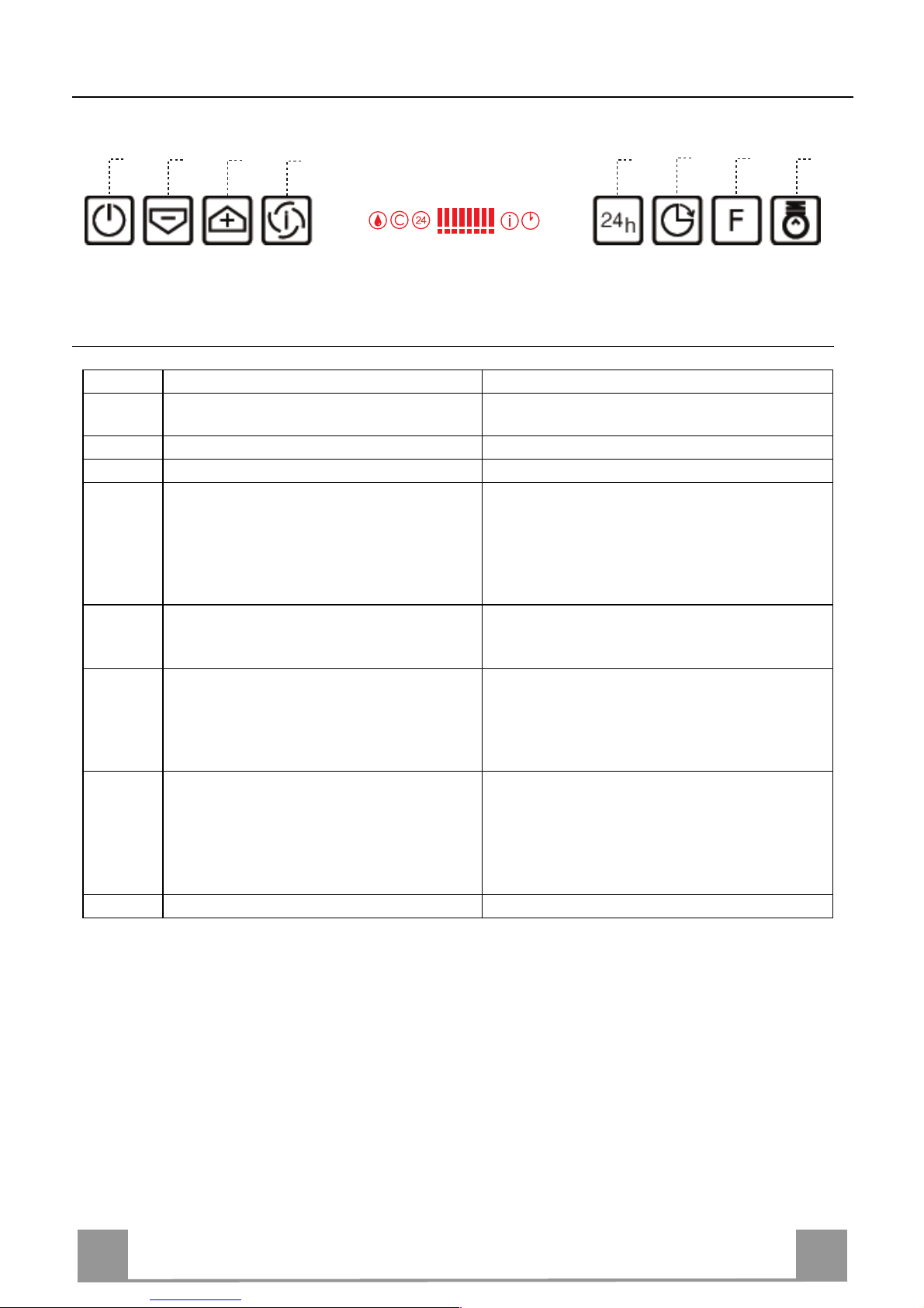
Control panel
Button Function Display
A Turns the suction motor on and off at the
last speed used.
Displays the speed set.
B Decreases the working speed. Decreases the lighted segments.
C Increases the working speed. Increases the lighted segments.
D Activates intensive speed from any other
speed, including motor off. This speed is
timed to run for 10 minutes, after which
the system will return to the speed that
was previously set. Suitable for dealing
with severe cooking fumes.
I flashes and the segments on the Display are
all lit.
It is disabled by pressing the Button.
E Starts the motor at a speed that allows a
suction of 100 m
3
/h for 10 minutes every
hour, after which the motor stops.
Displays 24 and the segments on the Display,
initially all lit, turn off one at a time in cycle.
It is disabled by pressing the Button.
F Activates automatic switch-off with a 30’
delay. Suitable to complete elimination of
residual odours. Can be activated from any
position, it is deactivated by pressing the
button of turning the motor off.
Displays a flashing Clock symbol.
It is disabled by pressing the Button.
G Performs a Reset of the Filter saturation
alarm when the button is pressed for approximately 2 seconds.
After 100 hours operation the Drop symbol is
displayed to indicate saturation of the Metal
Grease Filters.
After 200 hours operation the letter C is displayed to indicate saturation of the Activated
Charcoal Filters.
H Turns the Lighting System on and off.
Keyboard Lock Command: it is possible to lock the keyboard, for example when cleaning the
Glass, when the Hood Motor and Lights are turned off.
Press F (Delay) for approximately 5 seconds to enable or disable Keyboard Locking, which is
always confirmed by a Beep and an animated signal on the display motor bar.
B
A
D
C
E
H
G
F
EN
2
22
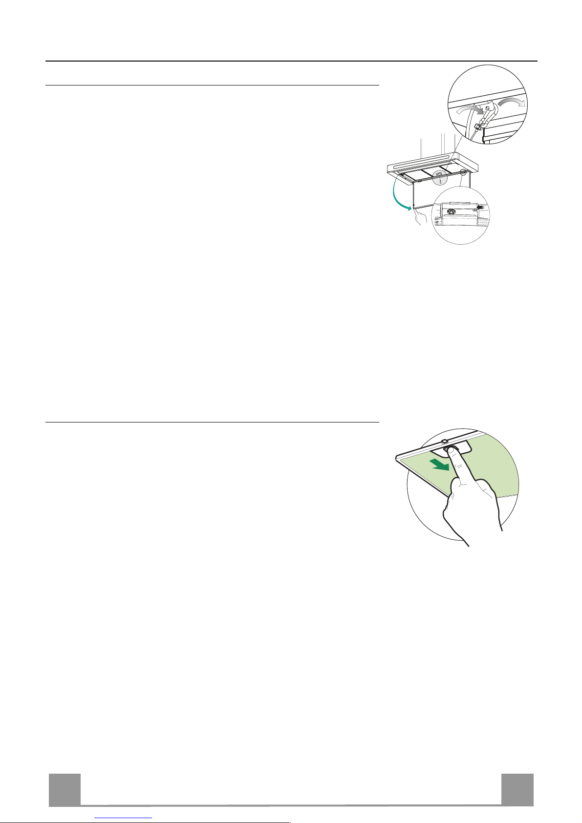
MAINTENANCE
Cleaning the Comfort Panels
• Pull the Comfort Panel to open it.
• Unhook the security chain by opening the spring catch.
• Disconnect the panel from the hood canopy by sliding the fixing pin lever.
• The comfort panel must never be washed in a dishwasher.
• Clean the outside by using a damp cloth and neutral liquid detergent.
• Clean the inside as well by using a damp cloth and neutral detergent; do not use wet cloths or sponges, or jets of water; do
not use abrasive substances.
• When the above operation has been completed, hook the panel
back and the spring catch to the hood canopy and close it by
turning the knob in the opposite direction.
11
22
Metal grease filters
Metal filters can be washed also in a dish machine. They need to
be washed every time a drop-symbol appears in the display or at
least every two months. In case of very frequent use these have to
be washed even more often.
Alarm reset
• Press the G-key for at least 2 seconds.
Cleaning
• Open the comfort panel.
• Remove the filters one by one by pushing them backwards and
pulling them down contemporaneously.
• Wash the filters. Pay attention not to bend them. Make sure
that filters are completely dry before putting them into their
seat. (a possible modification of the filter surface doesn’t influence its efficiency).
• Place the filters again into their seats and make sure that the
handle of the filter remains outside.
• Close the comfort panel.
EN
2
23
Charcoal filter (recycling version)
This filter cannot be washed or regenerated. It must be replaced when the C appears on the
display or at least once every 4 months. The filter saturation alarm has to be activated already
before.
Activation of the alarm signal
• In the recycling version hoods the filter saturation alarm must be activated during the installation or later.
• Switch off the hood and the lights.
• Press the E-key for about 5 seconds until the last two segments of the motor LEDS are lit on
the display.
• By releasing the E-key the clock icon starts to flash.
• Within 3 seconds press the D-key to activate/deactivate charcoal filter saturation alarm.
• C-symbol lit - charcoal filter saturation alarm ACTIVATED.
• C-symbol unlit - charcoal filter saturation alarm DEACTIVATED.
SUBSTITUTION OF THE CHARCOAL FILTER
Alarm reset
• Switch off the motor and the lighting system.
• Press the G-key for at least 2 seconds.
Substitution of the filter
• Open the confort panel.
• Remove the metal grease filters.
• Remove the charcoal filter as indicated in the picture.
• Place the filter again into its seat.
• Place again the metal grease filters into their place.
Lighting
CHANGING LAMP
16 W Neon Lamp
• Open the comfort panel.
• Remove the neon lamp guard by unfastening the screws and
sliding it out of its housing.
• Change the Neon lamp or the Starter, taking care to ensure that
the new components have the same characteristics as the old
ones.
• Replace the neon lamp guard.
• Close the comfort panel.
 Loading...