

FRANKE FKU908-STCXS User Manual

Instructions for use and installation
Cooker Hood
Istruzioni per l’uso e l’installazione
Cappa
Mode d’emploi et installation
Hotte de Cuisine
Bedienungsanleitung und Einrichtung
Dunstabzugshaube
Kullan
ım ve montaj talimatları
Davlumbaz
FKU 908-H TC
GB
IT
FR
DE
TR

EN
2
2
Instructions Manual
INDEX
RECOMMENDATIONS AND SUGGESTIONS......................................................................................................................7
CHARACTERISTICS..............................................................................................................................................................8
INSTALLATION ......................................................................................................................................................................9
USE.......................................................................................................................................................................................12
MAINTENANCE....................................................................................................................................................................13

IT
3
3
Libretto di Istruzioni
INDICE
CONSIGLI E SUGGERIMENTI ............................................................................................................................................16
CARATTERISTICHE............................................................................................................................................................17
INSTALLAZIONE..................................................................................................................................................................18
USO......................................................................................................................................................................................21
MANUTENZIONE.................................................................................................................................................................22

FR
4
4
Manuel d’Instructions
SOMMAIRE
CONSEILS ET SUGGESTIONS ..........................................................................................................................................25
CARACTERISTIQUES.........................................................................................................................................................26
INSTALLATION ....................................................................................................................................................................27
UTILISATION........................................................................................................................................................................30
ENTRETIEN..........................................................................................................................................................................31

DE
5
5
Bedienungsanleitung
INHALTSVERZEICHNIS
EMPFEHLUNGEN UND HINWEISE....................................................................................................................................34
CHARAKTERISTIKEN..........................................................................................................................................................35
MONTAGE............................................................................................................................................................................36
BEDIENUNG.........................................................................................................................................................................39
WARTUNG............................................................................................................................................................................40

TR
6
6
Kullanim Kilavuku
IÇERIKLER
TAVSIYELER VE ÖNERILER ..............................................................................................................................................43
ÖZELLIKLER........................................................................................................................................................................44
MONTAJ...............................................................................................................................................................................45
KULLANIM............................................................................................................................................................................48
BAKIM...................................................................................................................................................................................49

EN
7
7
RECOMMENDATIONS AND SUGGESTIONS
The Instructions for Use apply to several versions of this appliance. Accordingly, you
may find descriptions of indi vidual feat ures t hat do not apply t o your specif ic appli ance.
INSTALLATION
• The manufac turer will not be held liable for any damages res ulting from incorrec t or
improper install ation.
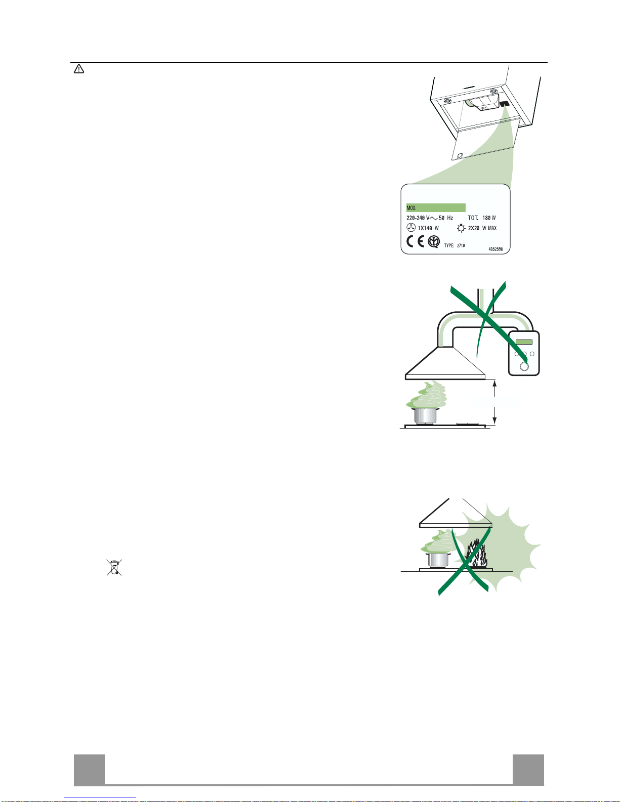
• The minimum safety distance between the cooker top and the extractor hood is 550
mm.
• Check that the mains voltage corresponds to that indicated on the rating plate fixed to
the inside of the hood.
• For Class I appliances, check that the domestic power supply guarantees adequate
earthing.
Connect the extract or t o the exhaust flue throu gh a pipe of minimum diameter 120 mm.
The route of the flue must be as short as possi ble.
• Do not connect the extractor hood to exhaust ducts carrying combustion fumes (boilers, fireplaces, etc. ).
• If the extractor is used in conjunction with non-electrical appliances (e.g. gas burning
appliances), a sufficient degree of aeration must be guaranteed in the room in order to
prevent the backflow of exhaust gas. The kitchen must have an opening communicating directly with the open ai r i n order to guaran t ee the ent ry of cl ean ai r.
USE
• The extractor hood has been designed exclusively for domestic use to eliminate
kitchen smells.
• Never use the hood for pur poses other t han fo r w hich it has ben designed.
• Never leave high naked fl ames under t he hood w hen it is in oper ati on.
• Adjust the flame intensity to direct it ont o the bottom of the pan only, making sure that it
does not engulf the si des.
• Deep fat fryers must be continuously monitored during use: overheated oil can burst
into flames.
• Do not flambè under the range hoo d; risk of fire
• This appliance is not intended for use by persons (including children) with reduced
physica l, senso ry or men tal capa bilities, o r lack of expe rience and knowledge, unless
they have been given supervision or instruction concerning use of the appliance by a
person responsible for t heir safet y.
• Children should be supervised to ensure that they do not play with the appliance.
MAINTENANCE
• Switch off or unplug t he appliance from the mains supply before carrying out any maintenance work.
• Clean and/or replace the Fi l ters af ter the speci fi ed time peri od.
• Clean the hood using a damp cl oth and a neutral liquid deter gent.
The symbol on the product or on its packaging indicates that this product may not be treated as
household waste. Instead it shall be handed over to the applicable collection point for the recycling of
electrical and electronic equipment. By ensuring this product is disposed of correctly, you will help prevent potential negative consequences for the environment and human health, which could otherwise be
caused by inappropriate waste handling of this product. For more detailed information about recycling of
this product, please contact your local city office, your household waste disposal service or the shop
where you purchased the product.
550 mm min.
EN
8
8
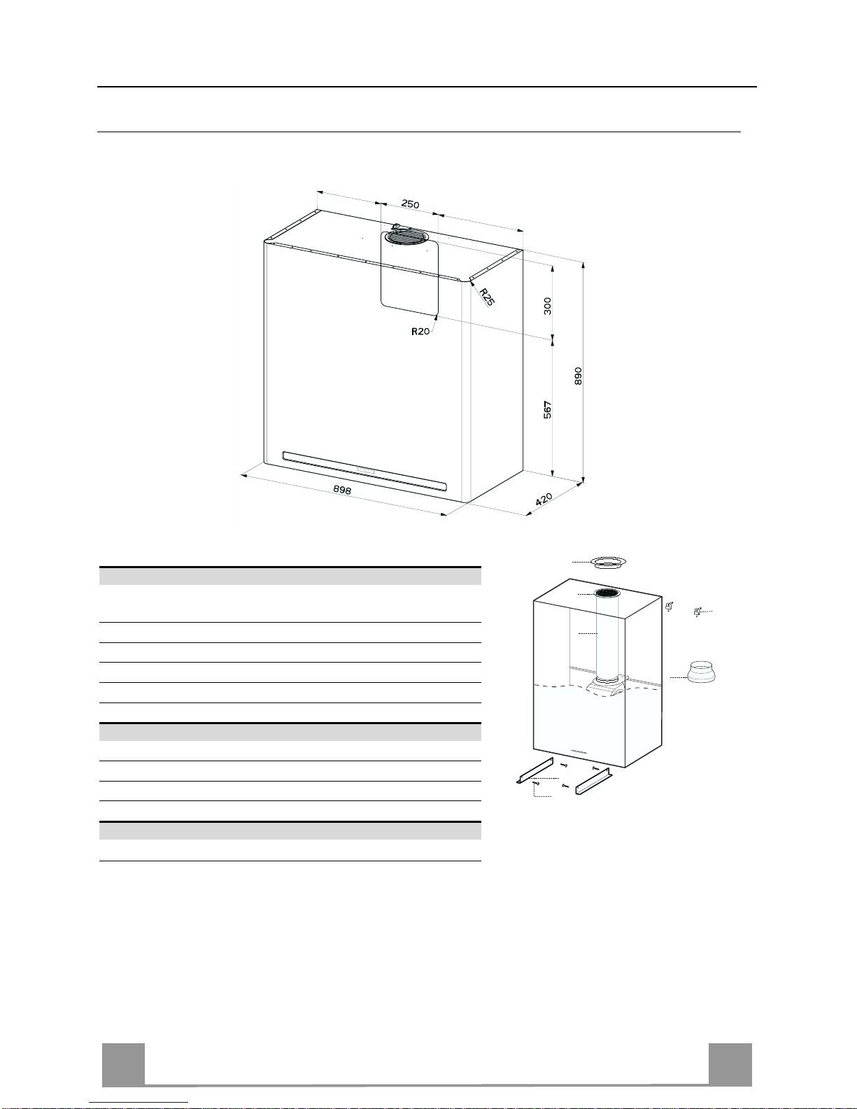
CHARACTERISTICS
Dimensions
Components
Ref. Q.ty Product components
1 1 Hood Body complete with: Controls, Light, Suction Unit,
Filters, Lower Duct
7 1 PVC Pipe (fi tted)
8 1 Inclinable grid (fitted)
9 1 Reduction flange ø 150-120 mm
10 1 Metal cover
Ref. Q.ty Assembly components
7.5 2 Glass Support Corners
11a 2 SB 12/10 Plugs
12c 4 Screws 2,9 x 6,5
Q.ty Documents
1 Instruction Manual
9
12c
11a
8
7
7.5
10
EN
9
9
Hood type 90
X 380
550 mm min
11a
X
808
570 300
250
X
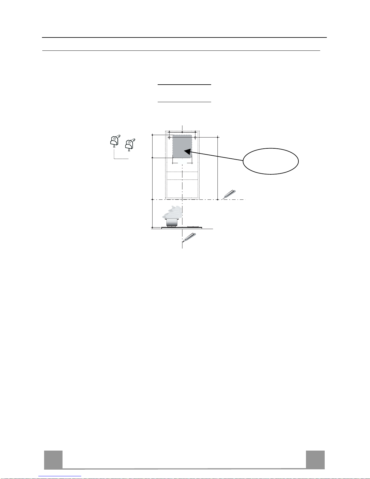
INSTALLATION
Boring the wall
If you want to use the hood in suction version with the air outlet at th e back of the hood, make
sure to follow the indications given below in the drawing for a correct boring operation of the air
outlet opening.
When installing the h ood in recycling version it has to be taken into consideratio n that space remaining between the hood and the upper limit (ceiling or self) is at least 8-10 cm.
On the wall, trace:
• a vertical line up to the ceiling or top limit, at the centre o f the area where you intend to fit
the hood;
• a horizontal line at: 550 mm min. above the cooking hob;
• As shown, mark a reference point at 808 mm above the horizontal reference line, and at X
mm (X= see table in figure) to the right of the vertical reference line.
• Repeat this operation on the opposite side, checking levelling.
• Drill the points marked using a ø 12 mm bit
• Insert plugs with screws and brackets 11a in the holes then tighten them.
Rear air outlet
zone
EN
110
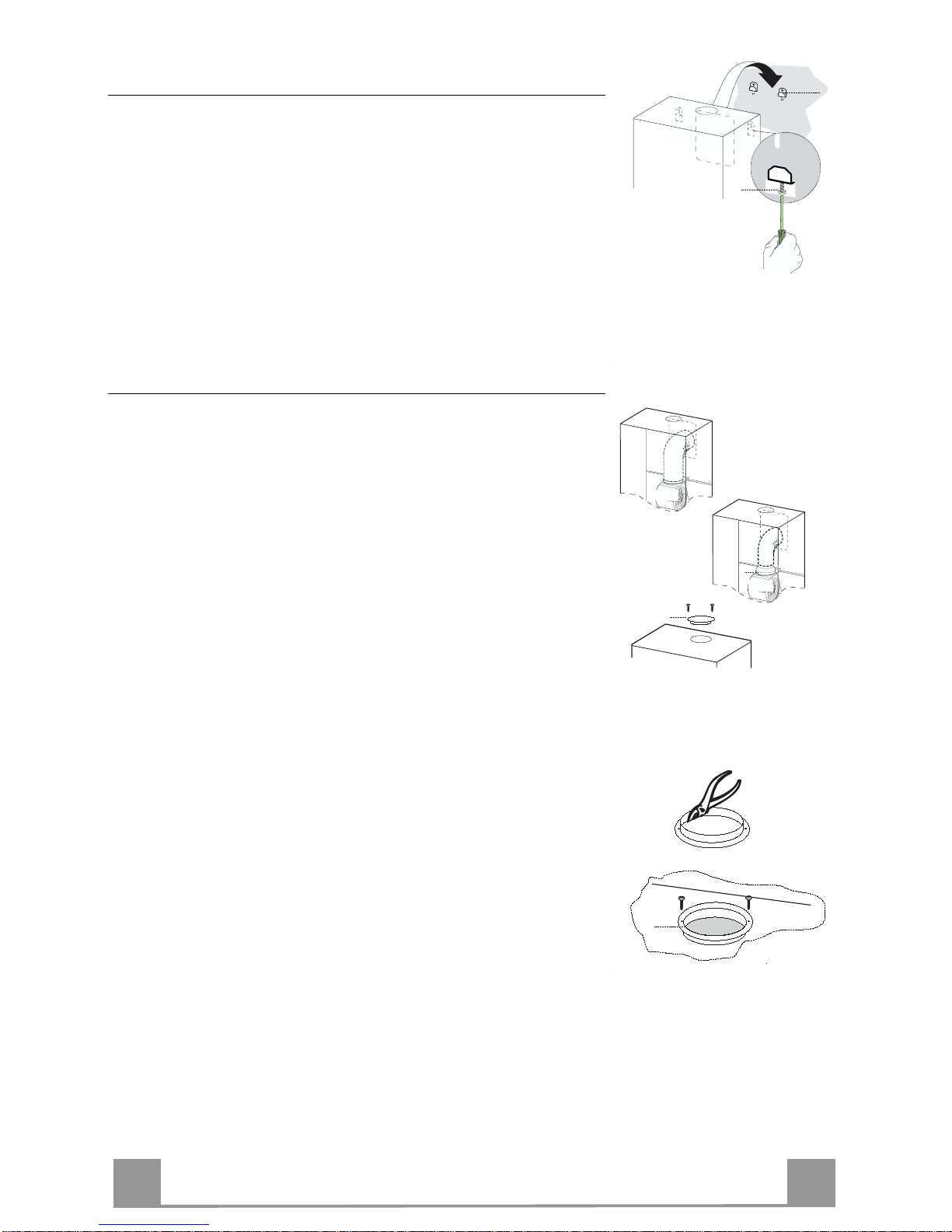
Hood body assembly
• Adjust the two screws Vr of brackets 11a, by just placing them
in position.
• Hook the hood body to the two brackets 11a.
• Pull the Comfort Panel to open it, remove the filters one by
one, push them towards the rear part of the unit and pull
downwards at the same time .
• From inside the hood body, tighten the screws Vr to level the
body.
Vr
11a
Connection
AIR OUTLET IN A DUCTING HOOD VERSION
When installing the hood in ducting version, basing on the installer’s choice, a rigid or a flexible pipe with a ø 150 or 120 mm
is used in order to connect the hood to the air outlet piping. The
pipe connection can be made on the upper part or on the rear side
of the hood.
Before connecting the hood to the air outlet ducting remove the
lateral air outlet grid 8 and the plastic tube 7. The adapting flan ge
9 has to be removed only in case the connecting diameter is 150.
REAR AI R OU T L E T
• When drilling the air outlet hole in the wall proceed in accordance with the scheme in the part concerning the wall drilling.
• Use a pair of tongs when br eakin g th e rear air out let ho le in th e
wall.
• In case the connection is made by using a ø 120 mm pipe insert
the reduction flange 9 on the hood body outlet.
• Fix the pipe with an adequate quantity of pipe clamps. This
material is not supplied together with the hood.
• Remove the charcoal filter if present.
• Fix the metal cover 10 to the upper air outlet hole of the hood
by using the screws supplied.
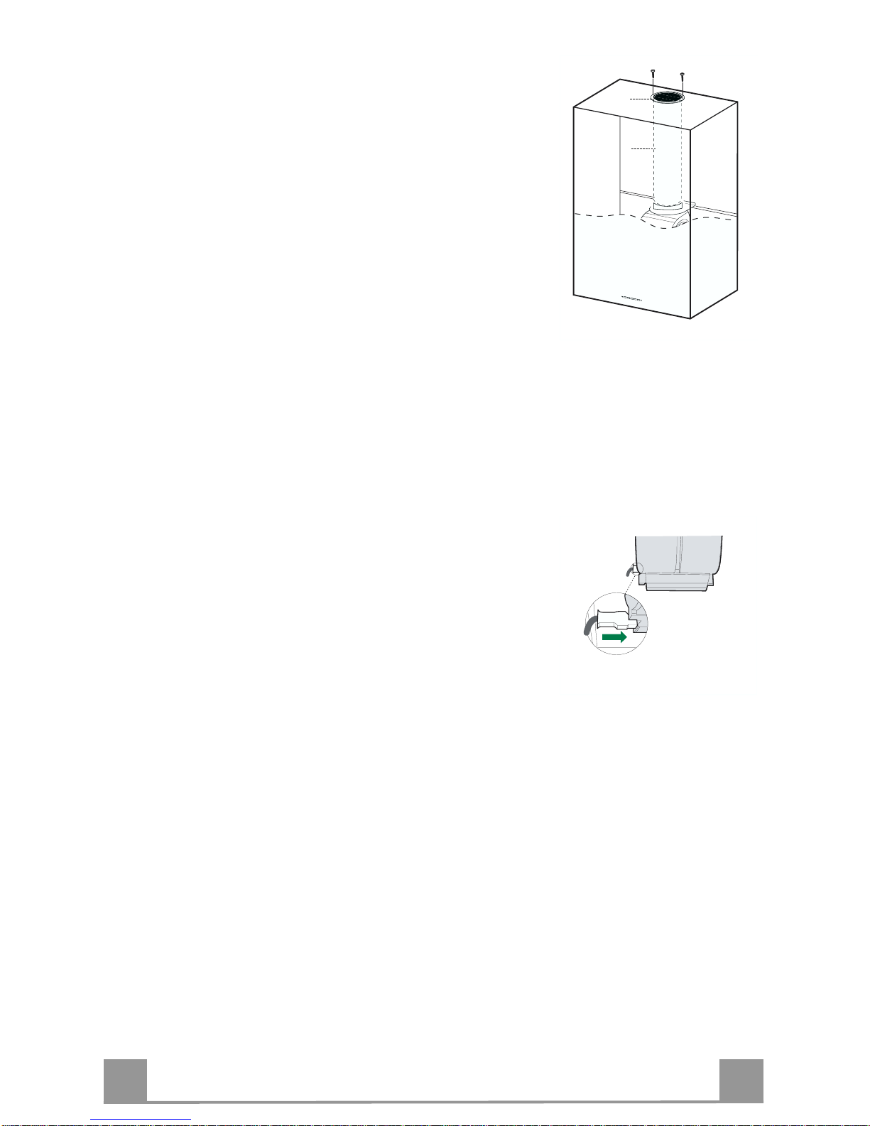
UPPER AIR OUTLET
• In case the connection is made by using a ø 120 mm pipe insert
the reduction flange 9 on the hood body outlet.
• Use a pair of tongs when removing th e cen tral part of the metal
cover 10. Fix the cover to the air outlet hole of the hood by using the screws supplied.
• Fix the pipe with an adequate quantity of pipe clamps. This
material is not supplied together with the hood.
• Remove the charcoal filter if present.
ø 150
9
ø 120
10
10
EN
111
AIR OUTLET IN A RECYCLING HOOD VERSION
• In case the components requested for the recycling functioning
have been removed earlier these have to be positioned again.
• Put the p lastic tube onto the flange 7.
• Place the ai r outlet grid 8 on the air outlet. Make sure that the
position of the grid is correct.
• Make sure that charcoal filters have been placed inside the
hood.
8
7
ELECTRICAL CONNECTION
• Connect the hood to the mains through a two-pole switch having a contact gap of at least 3 mm.
• Remove the grease filters (see paragraph Maintenance) being
sure that the co nnector of the feeding cable is correctly inserted
in the socket placed on the side of the fan.
EN
112
USE
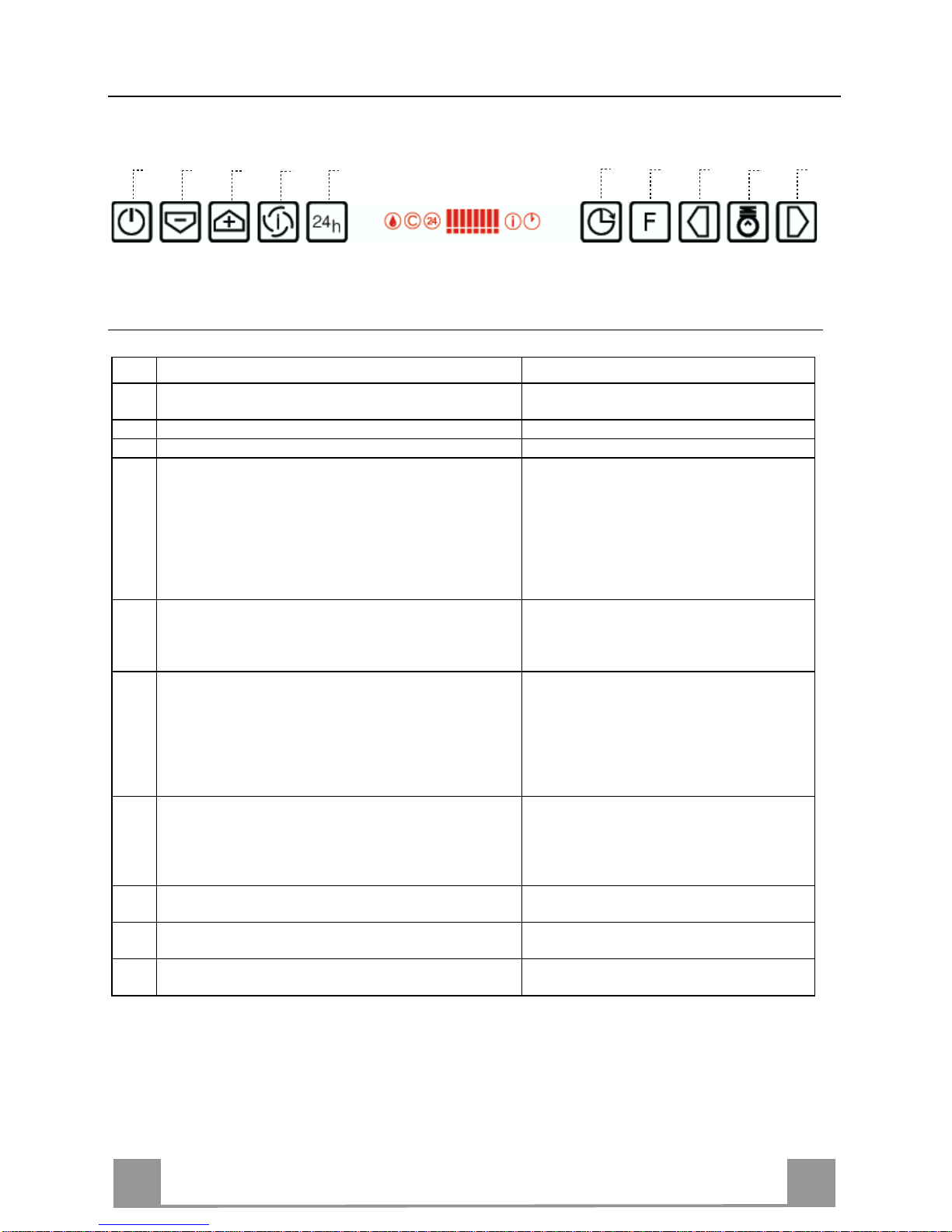
Control board
Key Function Display
A
Switches the extractor motor on and off at the latest
selected speed
Indicates the selected speed.
B Decreases the suct ion speed. The numb er of lit LEDS decreases.
C Inc reases the suction speed. The number of lit LEDS increases.
D By pressing this key it is possible to start the inten-
sive speed from any previously selected speed except the Delay-function and 24H-function. This
speed has been timed at 10 minutes. After that time
the system activates automatically the latest selected
speed. This function is suitable for cooking conditions when vapours and smells are at the utmost emission.
I flashes and the LEDS are all lit.
By pressing the key the function is
stopped.
E By pressing this key it is possible to set up the motor
to a suction speed at 100 m
3
/h .
24 appears a nd the LEDS extinguish one
by one.
By pressing the key the function is
stopped
F By pressing this key it is possible to set the delayed
shutdown of the motor and the lighting to 30 minutes. This function is suitable for a complete elimination of resi dual cookin g odours. Fu nctionin g only
when the mot or is on(n ot du ring th e 24H-fu nc tion or
intensive function). By pressing the key the function
is stopped
A flashing clock-symbol appears.
By pressing the key the function is
stopped
G By pressing this key for about 2 seconds it is possi-
ble to reset the filter saturation alarm
After 100 working hours a drop-symbol
appears. Metal grease filters have to be
washed.
After 200 working hours C appears.
Charcoal filters have to replaced.
H By pressing this key the intensity of the lighting
system can be decreased.
I Switches on/ off th e lightin g system at th e maximu m
intensity.
L By pressing this key the intensity of the lighting
system can be increased.
Keyboard lock: it is possible to jam the ke yboard when, for examp le, cleaning the gl ass. The
motor and lights are switched off.
By pressing the F-key (Delay) for about 5 seconds the keyboard block can be activated or deactivated. This function is confirmed by a Beep and by moving motor LEDS on display.
B
A
D
C
E
G
F
I
H
L
EN
113
MAINTENANCE
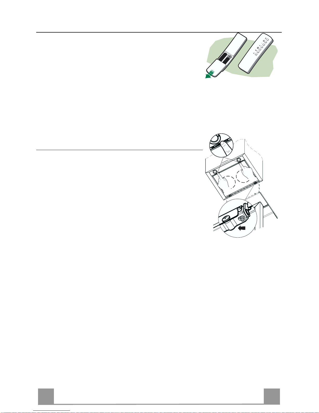
REMOTE CONTROL (OPTIONAL)
The appliance can be controlled using a remote control powered
by a 1.5 V carbon-zinc alkaline batteries of the standard LR03AAA type.
• Do not place the remote control near to h eat sources.
• Used batteries must be disposed of in the proper manner.
Cleaning the Comfort Panels
• Pull the Comfort Panel to open it.
• Disconnect the panel from the hood canopy by sliding the fixing pin lever.
• The comfort panel must never be washed in a dishwasher.
• Clean the outside using a damp cloth and neutral liquid detergent.
• Clean the inside as well using a damp cloth and neutral detergent; do not use wet cloths or sponges, or jets of water; do not
use abrasive substances.
• When the above operation has been completed, hook the panel
back to the hood canopy and close it by turning the knob in the
opposite direction .

EN
114
Metal grease filters
Metal filters can be washed also in a dish machine. They need to
be washed every time a drop-symbol appears in the display or at
least every two months. In case of very frequent use these have to
be washed even more often.
Alarm reset
• Press the G-key for at least 2 seconds.
Cleaning
• Open the comfort panel.
• Remove the filters one by one by pushing them backwards and
pulling them down contemporaneously.
• Wash the filters. Pay attention not to bend them. Make sure
that filters are completely dry before putting them into their
seat. (a possible modification of the filter surface doesn’t influence its efficiency).
• Place the filters again into their seats and make sure that the
handle of the filter remains outside.
• Close the comfort panel.
EN
115
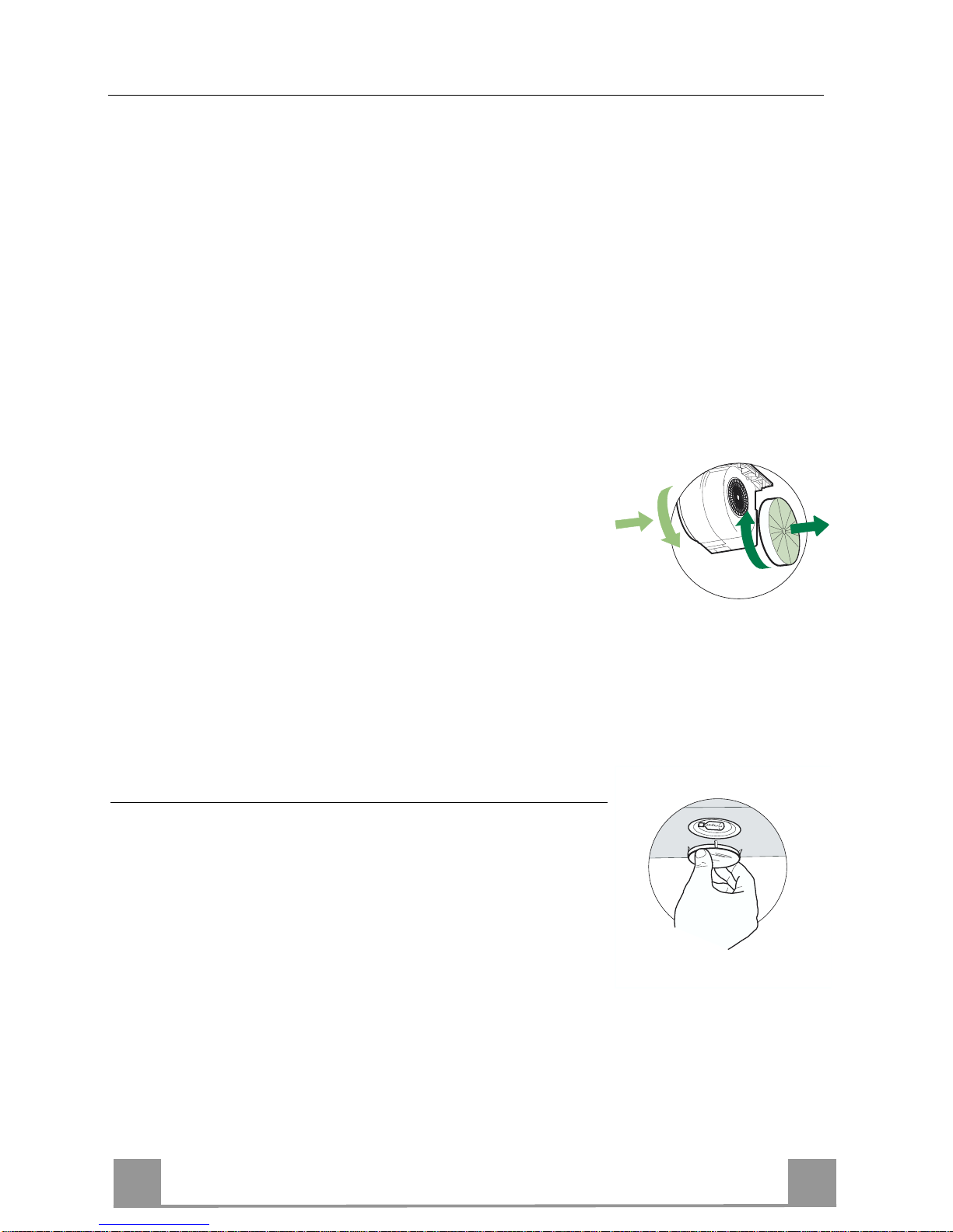
Charcoal filter (recycling version)
This filter cannot be washed or regenerated. It must be replaced when the C appears on the
display or at least once every 4 months. The filter saturation alarm has to be activated already
before.
Activation of the alar m signal
• In the recycling version hoods the filter saturation alarm must be activated during the installation or later.
• Switch off the hood and the lights.
• Press the E-key for about 5 seconds until the last two segments of the motor LEDS are lit on
the display.
• By releasing the E-key the clock icon starts to flash .
• Within 3 seconds press the D-key to activate/deactivate charco al filter saturation alarm.
• C-symbol lit - charcoal filter saturation alarm ACTIVATED.
• C-symbol unlit - charcoal filter saturation alarm DEACTIVATED.
SUBSTITUTION OF THE CHARCOAL FILTER
Alarm reset
• Switch off the motor and the lighting system.
• Press the G-key for at least 2 seconds.
Substitution of the filter
• Open the confort panel.
• Remove the metal grease filters.
• Remove the charcoal filter as indicated in the picture.
• Place the filter again into its seat.
• Place again the metal grease filters into their place.
A
B
Lighting
LIGHT REPLACEMENT
20 W halogen light.
• Remove the snap-on lamp cover by levering it from under the
metal ring, supporting it with one hand.
• Remove the halogen lamp from the lamp holder by pulling
gently.
• Replace the lamp with a new one of the same type, making
sure that you insert the two pins properly into the housings on
the lamp holder.
• Replace the sn ap-on lamp cover.
IT 116
CONSIGLI E SUGGERIMENTI
Questo libretto di istruzioni per l'uso è previsto per più versioni dell' apparecchio.
É possibile che si ano descritti singol i particolari della dotazion e, che non riguarda no il
Vostro apparecchio.
INSTALLAZIONE
• Il produttore declina qualsiasi responsabilità per danni dovuti ad installazione non corretta
o non conforme a lle regole dell’arte.
• La distanza minima di sicurezza tra il Piano di cottura e la Cappa deve essere di 550 mm.
• Verificare che la tensione di rete corrisponda a quella riportata nella targhetta posta
all’interno della Cappa.
• Per Apparec chi in Classe Ia accer tarsi che l’impian to elettrico domes tico garantisca un
corretto sc arico a terra.
• Collegare la Cappa all’uscita dell’aria aspirata con tubazione di diametro pari o superiore
a 120 mm. Il percor so della tubazione deve essere il più brev e pos s i bi l e .
• Non col legare la Ca ppa a condot ti di scarico d ei fumi prod otti da combus tione (cald aie,
caminetti, ecc .) .
• Nel caso in cui nella stanza vengano utilizzati sia la Cappa che apparecchi non azionati
da energia el et tr i c a ( ad es empio appar ec c hi uti l izzatori di g as ) , si deve provv ed er e ad una
aerazione sufficiente dell’ambiente. Se la cucina ne fosse sprovvista, praticare
un’apertura che comunichi con l’esterno, per garantire il richiamo d’aria pulita.
USO
• La Capp a è stata progett ata esclusivam ente per uso domes tico, per abbatter e gli odori
della cucina.
• Non fare mai uso improprio della Cappa.
• Non lasciare fiamme libere a forte intensità sotto la Cappa in funzione.
• Regol are sempre le fiamme in modo da evitare una evidente fuoriuscita laterale delle
stesse rispetto al fondo delle pentole.
• Controllare le fr iggitrici durante l’uso: l’olio surriscaldato pot rebbe infiammarsi.
• Non preparare alimenti flambè sotto la cappa da cucina; pericolo d'incendio.
• Questo apparecchio non deve essere utilizzato da persone (bambini inclusi) con ridotte
capacità ps ichiche, sensorial i o mentali, oppure da persone se nza esperienza e conoscenza, a meno che non siano controllati o istruiti all’uso dell’apparecchio da persone responsabili della loro sicurezza.
• I bambini devono essere supervisionati per assicurarsi che non giochino con
l’apparecchio.
MANUTENZIONE
• Prima di proc edere a qu alsias i oper azion e di m anut enzion e, dis inseri re l a Capp a togl iendo la spina elet trica o spegnendo l’interruttore genera le.
• Effettuare una scrupolosa e tempestiva manutenzione dei Filtri secondo gli intervalli consigliati.
• Per la pulizi a del le s uperfi ci del la Ca ppa è suf fi cient e uti li zzar e un pann o umi do e deter si vo liquido neutro.
Il simbolo sul prodotto o sulla confezione indica che il prodotto non deve essere considerato
come un normale rifiuto domestico, ma deve essere portato nel punto di raccolta appropriato per il
riciclaggio di apparecchiature elettriche ed elettroniche. Provvedendo a smaltire questo prodotto in
modo appropriato, si contribuisce a evitare potenziali conseguenze negative per l’ambiente e per la
salute, che potrebbero derivare da uno smaltimento inadeguato del prodotto. Per informazioni più
dettagliate sul riciclaggio di questo prodotto, contattare l’ufficio comunale, il servizio locale di smaltimento rifiuti o il negozio in cui è stato acquistato il prodotto.
550 mm min.
 Loading...