

Franke FGL 6015 XS, FGL 7015 XS, FGL 9015 XS, FDF 6154 XS, FDF 7154 XS Instructions For Use And Installation
...Page 1

Instructions for use and installation
Cooker Hood
Istruzioni per l’uso e l’installazione
Cappa
Mode d’emploi et installation
Hotte de Cuisine
Bedienungsanleitung und Einrichtung
Dunstabzugshaube
Kullan
ım ve montaj talimatları
Davlumbaz
FGL 6015 XS
FGL 7015 XS
FGL 9015 XS
IT
FR
DE
TR
GB
Page 2

2
2
INDEX
RECOMMENDATIONS AND SUGGESTIONS......................................................................................................................3
CHARACTERISTICS..............................................................................................................................................................4
INSTALLATION ......................................................................................................................................................................5
USE.........................................................................................................................................................................................8
MAINTENANCE......................................................................................................................................................................9
INDICE
CONSIGLI E SUGGERIMENTI ............................................................................................................................................10
CARATTERISTICHE............................................................................................................................................................11
INSTALLAZIONE..................................................................................................................................................................12
USO......................................................................................................................................................................................15
MANUTENZIONE.................................................................................................................................................................16
SOMMAIRE
CONSEILS ET SUGGESTIONS ..........................................................................................................................................17
CARACTERISTIQUES.........................................................................................................................................................18
INSTALLATION ....................................................................................................................................................................19
UTILISATION........................................................................................................................................................................22
ENTRETIEN..........................................................................................................................................................................23
INHALTSVERZEICHNIS
EMPFEHLUNGEN UND HINWEISE....................................................................................................................................24
CHARAKTERISTIKEN..........................................................................................................................................................25
MONTAGE............................................................................................................................................................................26
BEDIENUNG.........................................................................................................................................................................29
WARTUNG............................................................................................................................................................................30
IÇERIKLER
TAVSIYELER VE ÖNERILER ..............................................................................................................................................31
ÖZELLIKLER........................................................................................................................................................................32
MONTAJ...............................................................................................................................................................................33
KULLANIM............................................................................................................................................................................36
BAKIM...................................................................................................................................................................................37
EN
IT
FR DE TR
Page 3
EN
3
3
RECOMMENDATIONS AND SUGGESTIONS
The Instructi ons for Us e appl y t o seve ral ver sio ns of this appli anc e. Ac cor
d-
ingly, you may find descriptions of in dividual features th at do not apply to
your specific appliance.
INSTALLATION
• The manufactur er will not be held liable for any damages resultin g from incorrect or i mpr op er ins tal lat ion .
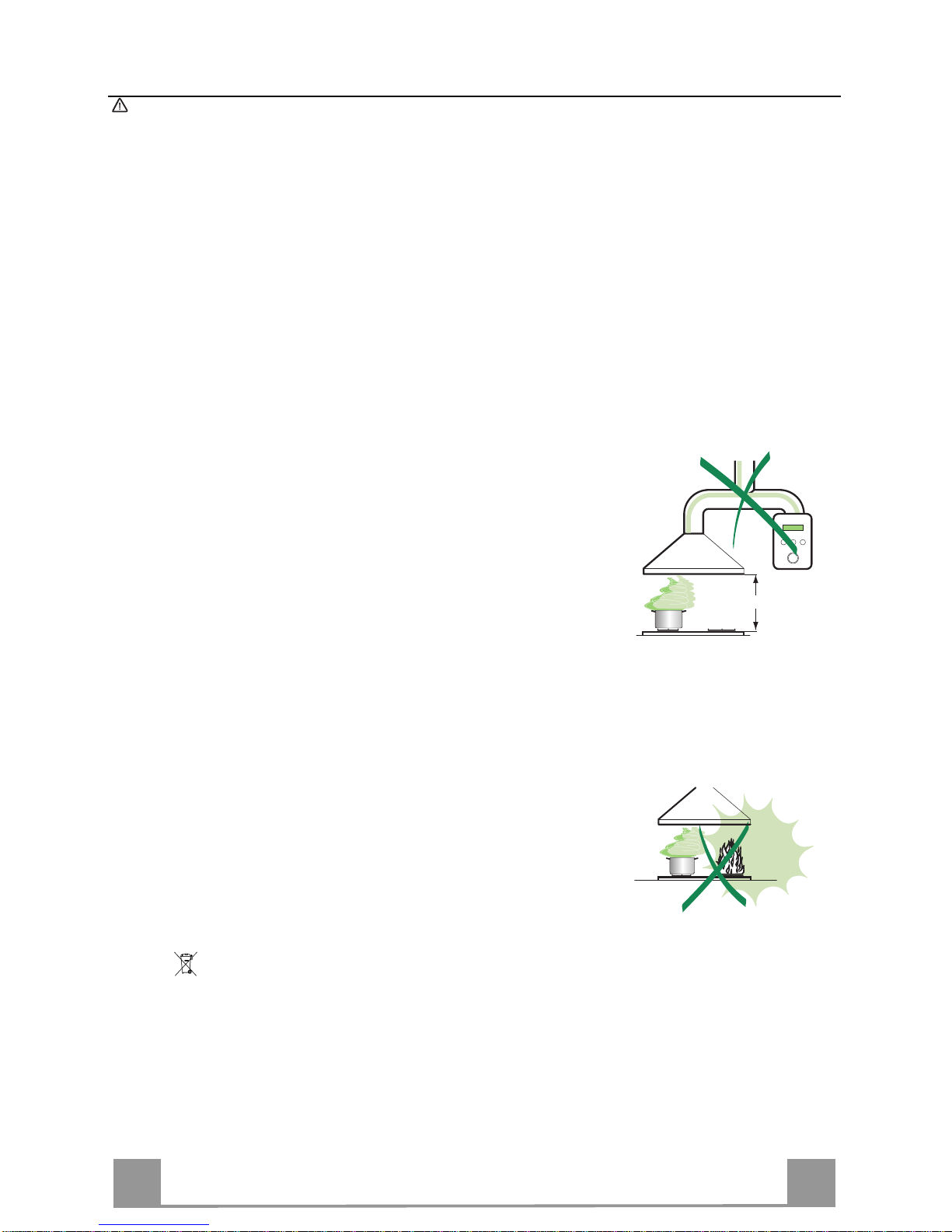
• The minimum safety distance between the cooker top and the extractor
hood is 650 m m (som e m od el s c an be installe d at a l ow er height, please refer to the paragraphs on working dimensions and installation).
• Check that the mains voltage corresponds to that indicated on the rating
plate fixed to the inside of the hood.
• For Class I appliances, che ck that the domestic power su pply guarantees
adequate earthing.
Connect the extr actor t o the exh aus t flue thr ough a pi pe o f mini mum di ame-
ter 120 mm. The route of the flue must be as short as possible.
• Do not connect the extractor hood to exhaust ducts carrying combustion
fumes (boilers, fireplaces, etc.).
• If the extractor is used in conjuncti o n with non-electrical applianc es ( e.g. gas
burning appl iances), a s ufficient degree of aeration mu st be guarant eed in
the room in orde r to preve nt the backflow of ex haust gas. The kit chen mus t
have an opening communicating directly with the open air in order to
guarantee the entry of clean air.
USE
• The extractor hood has been designed exclusively for domestic use to eliminate kitchen smells.
• Never use the hood for purposes other than for which it has been designed.
• Never lea ve high na ke d fla me s un de r the ho od wh en it i s in op er ati on .
• A djust th e flame intensity to direct it onto the bo ttom o f the pan only, m aki ng
sure that it does not engulf the sides.
• Deep fat fryers mus t be continuous ly monitored du ring use: over heated oil
can burst into flames.
• Do not flambè under the range hood; risk of fire
• This appliance is not intended for use by persons (incl uding children) with
reduced physi cal, sensory or m ental capabi lities, or lack o f experience an d
knowledge, unl ess th ey have been g iven su pervis ion o r instr ucti on con cern ing use of the appliance by a person responsible for their safety.
• Chi ldren should be s up ervised to ensur e that they do not pla y with t he appliance.
MAINTENANCE
• S wi tch of f or u nplug the appli an ce fr om the m ai ns s up pl y be fo re ca rr yi n g ou t
any maintenance work.
• Clean and/or replace the Filters after the specified time period (Fire hazard).
• Clean the hood using a damp cloth and a neutral liquid detergent.
The symbol on the product or on its packaging indicates that this product may not be treated
as household waste. Instead it shall be handed over to the applicable collection point for the
recycling of elec tr i cal and el ectronic eq uipment. By ensuring this product is di s p osed of c orrectly,
you will help prevent potential negative consequences for the environment and human health,
which could otherwise be caused by inappropriate waste handling of this product. For more
detailed information about recycling of this product, please contact your local city office, your
household waste disposal service or the shop where you purchased the product.
650 mm min.
Page 4

EN
4
4
CHARACTERISTICS
Dimensions
520
420
48
6
598 - 698 - 798 - 898
530
108
252
150
540
Min. 670
Max. 1000
260
300
63
4181
126
Min.
500mm
Min.
650mm
Components
Ref. Q.ty Product Components
1 1 Hood Body, complete with: Controls, Light, Blower,
Filters
2 1 Telescopic Chimney comprising:
2.1 1 Upper Section
2.2 1 Lower Section
9 1 Reducer Flange ø 150-120 mm
14.1 2 Air Outlet Connection Extension
15 1 Air Outlet Connecti on
Ref. Q.ty Installation Components
7.2.1 2 Upper Chimney Section Fixing Brackets
7.3 1 Air Outlet Connecti on Support
11 6 Wall Plugs
12a 6 Screws 4,2 x 44,4
12c 6 Screws 2,9 x 9,5
Q.ty Documentation
1 Instruction Manual
2.1
2.2
2
12c
12a
7.2.1 11
11
12a
9
7.3
14.1
15
1
Page 5

EN
5
5
11
12a
306
X
116
1÷2
116
650 min.
7.2.1
INSTALLATION
Wall drilling and bracket fixing
Wall marking:
• Draw a vertical line on the supporting wall up to the ceiling, or as high as practical, at the
centre of the area in which the hood will be installed.
• Draw a horizontal line at 650 mm above the hob.
• Place bracket 7.2.1 on the wall as shown about 1-2 mm from the ceiling or upper limit align-
ing the centre (n otch) with the vertical reference line.
• Mark the wall at the centr es of the holes in the bracket.
• Place bracket 7.2.1 on the wall as shown at X mm below the first bracket (X = height of the
upper chimney section supplied), aligning the centre (notch) with the vertical line.
• Mark the wall at the centres of the ho les in the bracket.
• Mark a reference poi nt as indicated at 116 mm from the vertical referen ce line and 306 mm
above the horizontal reference line.
• Repeat this operation on the other side.
• Drill ø 8 mm holes at all the centre points marked.
• Insert the wall plugs 11 in the hole s.
• Fix the lower bracket 7.2.1 using the 12a screws (4,2 x 44,4) supplied.
• Fix the upper bracket 7.2.1 and the air outlet connection support 7.3 together using the 2
screws 12a (4,2 x 44,4) supplied.
• Insert the two screws 12a (4,2 x 44,4) supplied in the hood body fixing holes, leaving a gap
of 5-6 mm between the wall and the head of the screw.
Page 6

EN
6
6
Mounting the hood body
• Before attaching the hood body, tighten the two screws Vr located on the hood body mounting points.
• Hook the hood body onto the screws 12a.
• Fully tighten the support screws 12a.
• Adjust the screws Vr to level the hood body.
12a
Vr
Connections
DUCTED VERSION AIR EXHAUST SYSTEM
When installing the ducted version, connect the hood to the
chimney using either a flexible or rigid pipe ø 150 or 120 mm,
the choice of which is left to the installer.
• To install a ø 120 mm air exhaust connection, insert the reducer flange 9 on the hood body outlet.
• Fix the pipe in position using sufficient pipe clamps (not supplied).
• Remove any activated charcoal filters.
9
ø 120ø 150
RECIRCULATION VERSION AIR OUTLET
• Insert th e connect ion extensi on pieces lat erally 14.1 in co nnection 15.
• Insert the Connector 15 into the Supp ort bracket 7.3 and fix it
with a screw.
• M ake sure that the outlet of the extensio n pieces 14.1 is horizontally and vertically aligned with the chimney outlets.
• Connect the air outlet connection 15 to the hood body outlet
using either a flexible or rigid pipe ø 150 mm, the choice of
which is left to the installer.
• Ensure that the activated charcoal filters have been inserted.
ø 150
15
14.1
7.3
Page 7

EN
7
7
ELECTRICAL CONNECTION
• Connect the hood to the mains through a two-pole switch having a contact gap of at least 3 mm.
• Remove the grease filters (see paragraph Maintenance) being
sure that the co nnector of the feeding cable is correctly inserted
in the socket placed on the side of the fan.
Flue assembly
Upper exhaust flue
• Slightly widen the two sides of the upper flue and hook them
behind the brackets 7.2.1, making sure that they are well
seated.
• Secure the sides to the br ackets by using the 4 screws 12c (2,9
x 9,5) supplied.
• Make sure that the outlet of the extensions pieces is aligned
with the chimney outlets.
Lower exhaust flue
• Slightly widen the two sides of the flue and hook them between the upper flue and the wall, making sure that they are
well seated.
• Fix the lower part laterally to the hood body by using the 2
screws 12c (2,9 x 9,5) supplied.
12c
12c
12c
2.1
2.2
2
7.2.1
Page 8

EN
8
8
USE
T2
T1
L
T3
Control panel
BUTTON LED FUNCTIONS
T1 Speed On Turns the Motor on at Speed one.
Turns the Motor off.
T2 Speed On Turns the Moto r on at Speed two.
T3 Speed Fixed When pressed bri efly, tu rns the Motor on at Speed three.
L Light Turns the Lighting System on and off.
Warning: Button T1 turns the motor off, after first passing to speed one.
Page 9

EN
9
9
MAINTENANCE
Grease filters
CLEANING METAL SELF- SUPPORTING GREASE FILTERS
• The filters must be cleaned every 2 months of operation, or
more frequently for particularly heavy usage, and can be
washed in a dishwasher.
• Remove the filters one at a time by pushing them towards the
back of the group and pulling down at the same time.
• Wash the filters, taking care not to bend them. Allow them to
dry before refitting.
• When refitting the filters, make sure that the handle is visible
on the outside.
Activated charcoal filter (Recirculation version)
REPLACING THE ACTIVATED CHARCOAL FIL T ER
• The filter is not washable and cannot be regenerated, and must
be replaced approximately every 4 months of operation, or
more frequently for particularly heavy usage.
• Re move the metal grease filters.
• Remove the saturated activated carbon filter by releasing the
fixing hooks.
• Fit the new filter by hooking it into its seating.
• Refit the metal grease filters.
Lighting
LIGHT REPLACEMENT
40 W incandescent lig ht.
• Re move the metal grease filters.
• Unscrew the bu lbs and repl ace them with n ew ones having t he
same characteristics.
• Replace the metal grease filters.
Page 10

436004820_ver1
Franke S.p.a.
Via Pignolini,2
37019 Peschiera del Garda (VR)
www.franke.it
 Loading...