

Page 1

Instructions for use and installation
Cooker Hood
Istruzioni per l’uso e l’installazione
Cappa
Mode d’emploi et installation
Hotte de Cuisine
Bedienungsanleitung und Einrichtung
Dunstabzugshaube
Kullanım ve montaj talimatları
Davlumbaz
FGL 915 I XS
GB
IT
FR
DE
TR
Page 2

2
2
INDEX
RECOMMENDATIONS AND SUGGESTIONS......................................................................................................................3
CHARACTERISTICS..............................................................................................................................................................4
INSTALLATION ......................................................................................................................................................................6
USE.......................................................................................................................................................................................10
MAINTENANCE....................................................................................................................................................................11
INDICE
CONSIGLI E SUGGERIMENTI ............................................................................................................................................12
CARATTERISTICHE............................................................................................................................................................13
INSTALLAZIONE..................................................................................................................................................................15
USO......................................................................................................................................................................................19
MANUTENZIONE.................................................................................................................................................................20
SOMMAIRE
CONSEILS ET SUGGESTIONS ..........................................................................................................................................21
CARACTERISTIQUES.........................................................................................................................................................22
INSTALLATION ....................................................................................................................................................................24
UTILISATION........................................................................................................................................................................28
ENTRETIEN..........................................................................................................................................................................29
INHALTSVERZEICHNIS
EMPFEHLUNGEN UND HINWEISE....................................................................................................................................30
CHARAKTERISTIKEN..........................................................................................................................................................31
MONTAGE............................................................................................................................................................................33
BEDIENUNG.........................................................................................................................................................................37
WARTUNG............................................................................................................................................................................38
IÇERIKLER
TAVSIYELER VE ÖNERILER ..............................................................................................................................................39
ÖZELLIKLER........................................................................................................................................................................40
MONTAJ...............................................................................................................................................................................42
KULLANIM............................................................................................................................................................................46
BAKIM...................................................................................................................................................................................47
EN
IT
FR DE TR
Page 3
EN
3
3
RECOMMENDATIONS AND SUGGESTIONS
The Instructi ons for Us e appl y t o seve ral ver sio ns of this appli anc e. Ac cor
d-
ingly, you may find descriptions of in dividual features th at do not apply to
your specific appliance.
INSTALLATION
• The manufactur er will not be held liable for any damages resultin g from incorrect or i mpr op er ins tal lat ion .
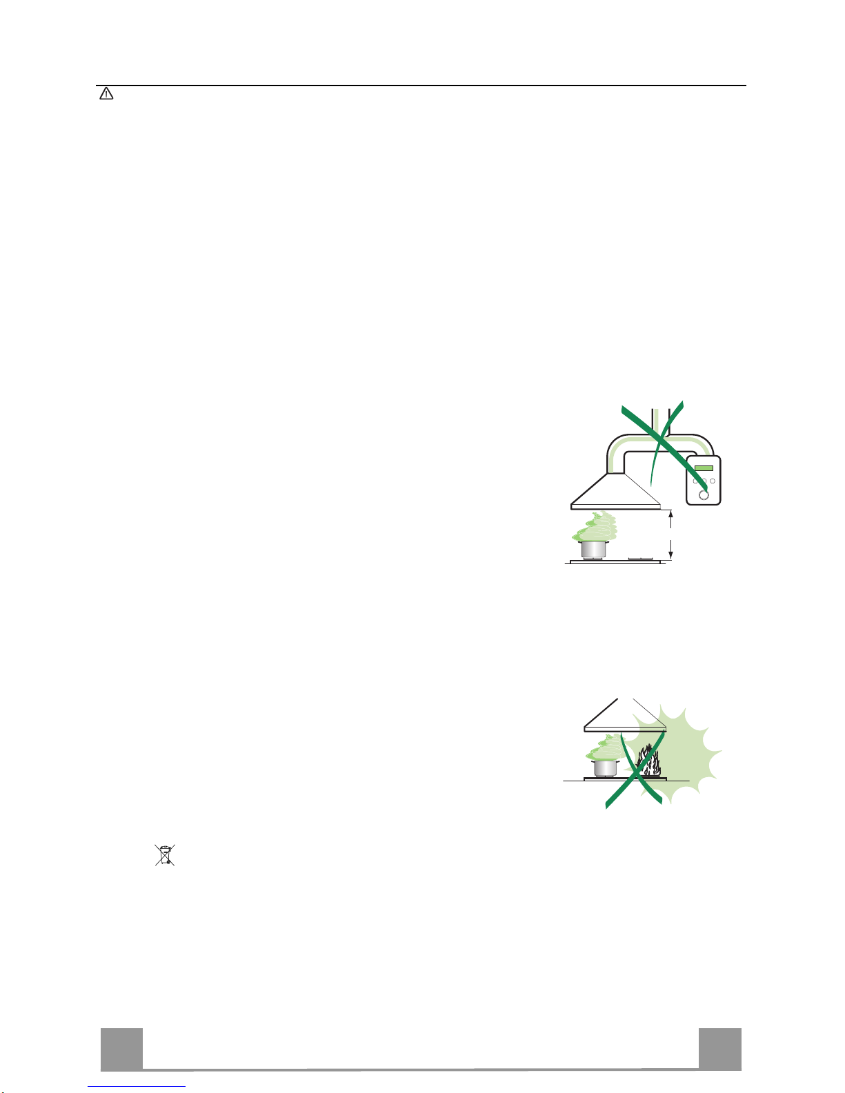
• The minimum safety distance between the cooker top and the extractor
hood is 650 m m (som e m od el s c an be installe d at a l ow er height, please refer to the paragraphs on working dimensions and installation).
• Check that the mains voltage corresponds to that indicated on the rating
plate fixed to the inside of the hood.
• For Class I appliances, che ck that the domestic power su pply guarantees
adequate earthing.
Connect the extr actor t o the exh aus t flue thr ough a pi pe o f mini mum di ame-
ter 120 mm. The route of the flue must be as short as possible.
• Do not connect the extractor hood to exhaust ducts carrying combustion
fumes (boilers, fireplaces, etc.).
• If the extractor is used in conjuncti o n with non-electrical applianc es ( e.g. gas
burning appl iances), a s ufficient degree of aeration mu st be guarant eed in
the room in orde r to preve nt the backflow of ex haust gas. The kit chen mus t
have an opening communicating directly with the open air in order to
guarantee the entry of clean air.
USE
• The extractor hood has been designed exclusively for domestic use to eliminate kitchen smells.
• Never use the hood for purposes other than for which it has been designed.
• Never lea ve high na ke d fla me s un de r the ho od wh en it i s in op er ati on .
• A djust th e flame intensity to direct it onto the bo ttom o f the pan only, m aki ng
sure that it does not engulf the sides.
• Deep fat fryers mus t be continuous ly monitored du ring use: over heated oil
can burst into flames.
• Do not flambè under the range hood; risk of fire
• This appliance is not intended for use by persons (incl uding children) with
reduced physi cal, sensory or m ental capabi lities, or lack o f experience an d
knowledge, unl ess th ey have been g iven su pervis ion o r instr ucti on con cern ing use of the appliance by a person responsible for their safety.
• Chi ldren should be s up ervised to ensur e that they do not pla y with t he appliance.
MAINTENANCE
• S wi tch of f or u nplug the appli an ce fr om the m ai ns s up pl y be fo re ca rr yi n g ou t
any maintenance work.
• Clean and/or replace the Filters after the specified time period (Fire hazard).
• Clean the hood using a damp cloth and a neutral liquid detergent.
The symbol on the product or on its packaging indicates that this product may not be treated
as household waste. Instead it shall be handed over to the applicable collection point for the
recycling of elec tr i cal and el ectronic eq uipment. By ensuring this product is di s p osed of c orrectly,
you will help prevent potential negative consequences for the environment and human health,
which could otherwise be caused by inappropriate waste handling of this product. For more
detailed information about recycling of this product, please contact your local city office, your
household waste disposal service or the shop where you purchased the product.
650 mm min.
Page 4
EN
4
4
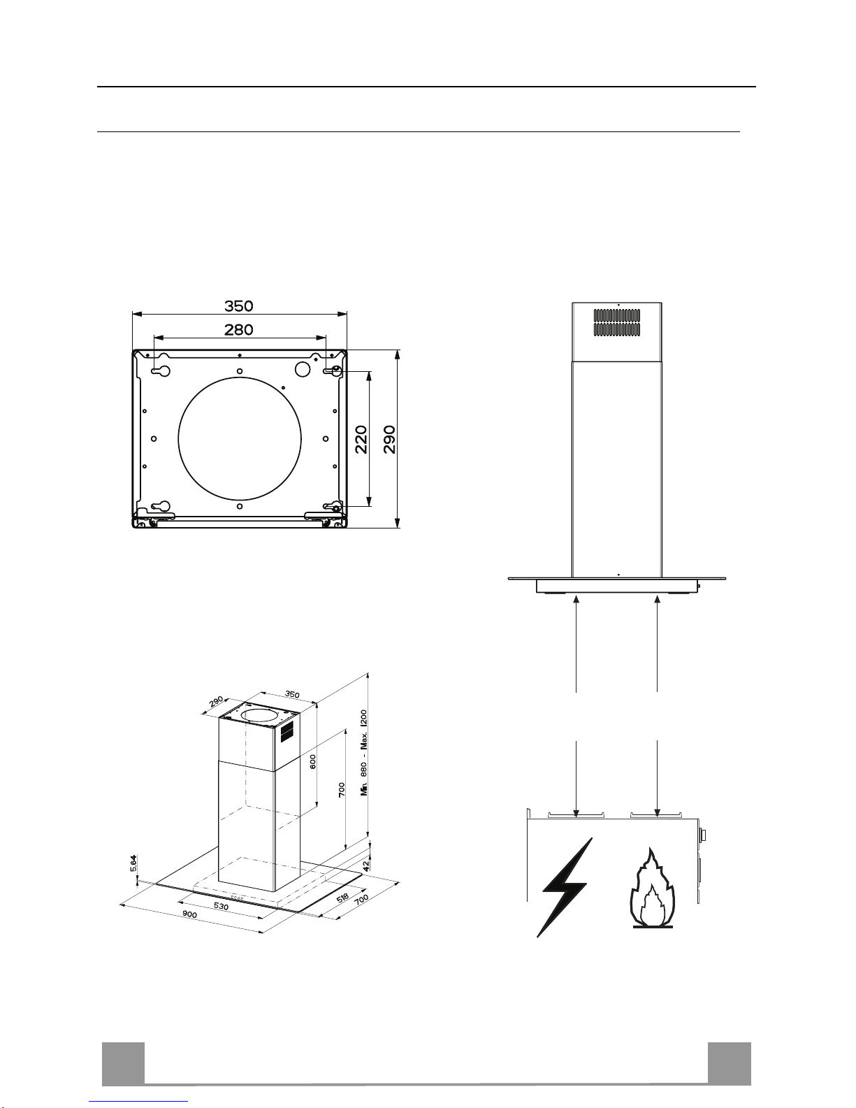
CHARACTERISTICS
Dimensions
Min.
500mm
Min.
650mm
Page 5

EN
5
5
Components
Ref. Q.ty Product Components
1 1 Hood Canopy complete with: Contr ols, Light, Filters
2 1 Telescopic chimney, made up of:
2.1 1 Upper chimney
2.2 1 Lower chimney
3 1 Telescopic panel, made up of:
3.1 1 Upper panel
3.2 1 Lower panel
9 1 Reduction flange ø 150-120 mm
14.1 1 Air Outlet Connect or Extension
15 1 Air Outlet C onnector
16 1 Novastick tape
25 Hose clamps (not supplied)
Ref. Q.ty Installation Components
7.1 1 Air outlet connector fixing bracket
7.2
1 Telescopic chim ney fixing bracket
11 4 Wall plugs ø 10
12c 2 Screws 2.9 x 6.5
12e 2 Screws 2.9 x 9.5
12f 4 Screws M4 x 80
12g 4 Screws M6 x 80
12h 4 Screws 5.2 x 70
21 1 Drilling template
22 4 Washers ø 6.4
23 4 Nuts M6
Q.ty Documentation
1 Instruction Manual
12h
11
12g
22
23
21
25
12f
7.2
12c
12e
9
3
3.1
3.2
2
2.1
2.2
1
1
14.1
15
7.1
16
Page 6

EN
6
6
INSTALLATION
Drilling the Ceiling/shelf and fixing the frame
DRILLING TH E CEILING/SHELF
• Use a plumb line to mark the centre of the hob on the ceiling/support shelf.
• Place the drilling template 21 provided on the ceiling/support shelf, making sure that the
template is in the correct position by lining up the axes of the template with those of the hob.
• Mark the centres of the holes in the template.
• Drill the holes at the points marked:
• For concrete ceilings, drill for plugs appropriate to the screw size.
• For hollow brick ceilings with wall thickness of 20 mm: drill ø 10 mm(immediately insert
the Dowels 11 supplied).
• For wooden beam ceilings, drill according to the wood screws used.
• For wooden shelf, drill ø 7 mm.
• For the power supply cable feed, drill ø 10 mm.
• For the air outlet (Ducted Version), drill accord ing to the diameter of the extern al air exhaust duct connection.
• Insert two screws of the following type, crossing them and leaving 4-5 mm from the ceiling:
• For concrete ceilings, use the appropriate plugs for the screw size (not provided).
• for Cavity ceiling with inner space, with wall thickness of approx. 20 mm, Screws 12h,
supplied.
• For wooden beam ceilings, use 4 wood screws (not provided).
• For wooden shelf, use 4 screws 12g with washers 22 and nuts 23, provided.
Page 7

EN
7
7
Fixing the Frame/Chimney
Should it be necessar y to adjust the heigh t of the frame, proceed
as follows:
• Unfasten the metric screws joining the two opposite parts that
can be seen from the front;
• Adjust the height of the frame as required, then replace the
screws removed as above, making sure that you insert 2 of
them close to the panel lock;
• Lift the frame, insert the slots onto the screws and slide them
until they lock;
• Tighten the two screws and insert the other two screws provided.
• Take the telescopic chimney locking bracket 7.2, remove the
film from the double sided adhesive and fix it inside the frame
so as to hold it more firmly.
Before final locking of the screws it is possible to make small
adjustments to the frame, making sure that the screws do not
come out of the adjustment slot.
• The Frame must be securely fastened both due to the weight of
the Hood and the stress caused by occasional sideways pressure on the Appliance when in position. When fastened, check
that the base is stable even when the Frame is subjected to
bending.
• In all cases where the Ceiling is not sufficiently strong at the
point of suspension, the Installation technician must strengthen
it with suitable plates and counterplates, anchored to structurally sound elements.
2
1
2
1
Ducted version air exhaust system Connection
When installing the ducted version, connect the hood to the
chimney using either a flexible or rigid pipe ø 150 or 120 mm,
the choice of which is left to the installer.
• To install a ø 120 mm air exhaust connection, insert the reducer flange 9 on the hood body outlet.
• Fix the pipe using the pipe clamps 25 (not provided).
• Remove any activated charcoal filters.
ø 150
9
ø 120
Page 8

EN
8
8
Air outlet – Recirculation Version
• Insert the Connector extensions 14.1 into the side of the Connector 15.
• Insert the Connector 15 into the Supp ort bracket 7.1 and fix it
with the screws.
• Fasten the S upport bracket 7.1, fixing it to the upper part with
the Screws.
• Make sure that the Connector extensions outlet 14.1 is in correspondence with the Chimney openings both horizontally and
vertically.
• Join the Connector 15 to the Hood canopy outlet using a rigid
or flexible pipe ø¸150 mm, selection of which is at the discretion of the installation technician.
• Make sure that the Activated charcoal odour filter has been
fitted.
7.1
7.1
12c
12e
15
14.1
Application of Novastick Tape
• Apply the Novastick tape 16 to the front edge of the Upper
Chimney from the top part down to the start of the Lower
Chimney.
Page 9

EN
9
9
Fitting the Panel and Fixing the Hood Canopy
Before fixing the Hood Canopy to the Frame:
• Remove the Grease filters from the Hood Canopy;
• Re move any Activated charcoal filters.
• Working from below, fix the Hood canopy to the Frame provided, using the 4 screws 12f (M6 x 10) provided.
• Then hook the upper part of the Panel 3, adjusted to size, to the
rubber supports in the upper part and in the lower part of the
Frame.
• Slide the lower part of the Panel 3 until its metal tabs slot into
the slots in the frame;
12f
ELECTRICAL CONNECTION
• Connect the hood to the mains through a two-pole switch having a contact gap of at least 3 mm.
• Remove the grease filters (see paragraph Maintenance) being
sure that the co nnector of the feeding cable is correctly inserted
in the socket placed on the side of the fan.
Page 10

EN
110
USE
T2
T1
L
T3
Control panel
BUTTON LED FUNCTIONS
T1 Speed On Turns the Motor on at Speed one.
Turns the Motor off.
T2 Speed On Turns the Moto r on at Speed two.
T3 Speed Fixed When pressed bri efly, tu rns the Motor on at Speed three.
Flashing Pressed for 2 Seconds.
Activates Speed four with a timer set to 10 minutes, after
which it returns to the speed that was set previously. Suitable
to deal with maximum levels of cooking fumes.
L Light Turns the Lighting System on and off.
Warning: Button T1 turns the motor off, after first passing to speed one.
Page 11

EN
111
MAINTENANCE
Grease filters
CLEANING METAL SELF- SUPPORTIN G GREASE FILTERS
• The filters must be cleaned every 2 months of operation, or
more frequently for particularly heavy usage, and can be
washed in a dishwasher.
• Remove the filters one at a time by pushing them towards the
back of the group and pulling down at the same time.
• Wash the filters, taking care not to bend them. Allow them to
dry before refitting.
• When refitting the filters, make sure that the handle is visible
on the outside.
Activated charcoal filter (Recirculation version)
REPLACING THE ACTIVATED CHARCOAL FIL T ER
• The filter is not washable and cannot be regenerated, and must
be replaced approximately every 4 months of operation, or
more frequently for particularly heavy usage.
• Re move the metal grease filters.
• Remove the saturated activated carbon filter by releasing the
fixing hooks.
• Fit the new filter by hooking it into its seating.
• Refit the metal grease filters.
Lighting
LIGHT REPLACEMENT
20 W halogen light.
• Remove the snap-on lamp cover by levering it from under the
metal ring, supporting it with one hand.
• Remove the halogen lamp from the lamp holder by pulling
gently.
• Replace the lamp with a new one of the same type, making
sure that you insert the two pins properly into the housings on
the lamp holder.
• Replace the snap-on lamp cover.
Page 12

436004901_ver1
Franke S.p.a.
Via Pignolini,2
37019 Peschiera del Garda (VR)
www.franke.it
 Loading...