

Page 1

Instructions for use and installation
Cooker Hood
Istruzioni per l’uso e l’installazione
Cappa
Mode d’emploi et installation
Hotte de Cuisine
Bedienungsanleitung und Installation
Dunstabzugshaube
Kullanım ve montaj talimatları
Davlumbaz
FGB 906 IS AC
GB
IT
FR
DE
TR
Page 2

2
2
INDEX
RECOMMENDATIONS AND SUGGESTIONS ..................................................................................................................... 3
CHARACTERISTICS ............................................................................................................................................................. 6
INSTALLATION...................................................................................................................................................................... 8
USE ...................................................................................................................................................................................... 12
MAINTENANCE................................................................................................................................................................... 14
INDICE
CONSIGLI E SUGGERIMENTI............................................................................................................................................ 16
CARATTERISTICHE............................................................................................................................................................ 19
INSTALLAZIONE ................................................................................................................................................................. 21
USO...................................................................................................................................................................................... 25
MANUTENZIONE ................................................................................................................................................................ 27
SOMMAIRE
CONSEILS ET SUGGESTIONS.......................................................................................................................................... 29
CARACTERISTIQUES......................................................................................................................................................... 32
INSTALLATION.................................................................................................................................................................... 34
UTILISATION ....................................................................................................................................................................... 38
ENTRETIEN......................................................................................................................................................................... 40
INHALTSVERZEICHNIS
EMPFEHLUNGEN UND HINWEISE ................................................................................................................................... 42
CHARAKTERISTIKEN......................................................................................................................................................... 45
MONTAGE ........................................................................................................................................................................... 47
BEDIENUNG........................................................................................................................................................................ 51
WARTUNG........................................................................................................................................................................... 53
IÇERIKLER
TAVSIYELER VE ÖNERILER.............................................................................................................................................. 55
ÖZELLIKLER........................................................................................................................................................................ 58
MONTAJ............................................................................................................................................................................... 60
KULLANIM ........................................................................................................................................................................... 64
BAKIM .................................................................................................................................................................................. 66
EN
IT
FR
DE
TR
Page 3
EN
3
3
RECOMMENDATIONS AND SUGGESTIONS
The Instructions for Use apply to several versions of this appliance.
Accordingly, you may find descriptions of individual features that do not
apply to your specific appliance.
INSTALLATION
• The manufacturer will not be held liable for any damages resulting from in-
correct or improper installation.
• The minimum safety distance between the cooker top
and the extractor hood is 650 mm (some models can
be installed at a lower height, please refer to the
paragraphs on working dimensions and installation).
• Check that the mains voltage corresponds to that indicated on the rating plate fixed to the inside of the
hood.
• For Class I appliances, check that the domestic
power supply guarantees adequate earthing.
Connect the extractor to the exhaust flue through a pipe of minimum diameter 120 mm. The route of the flue must be as short as possible.
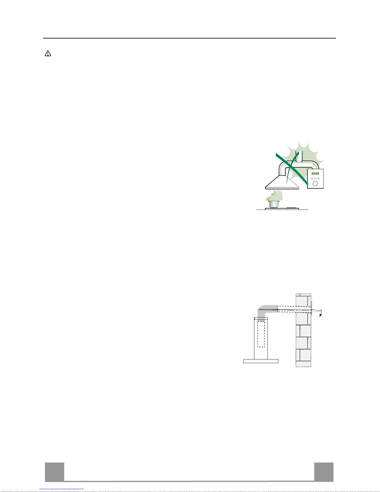
• Do not connect the extractor hood to exhaust ducts carrying combustion
fumes (boilers, fireplaces, etc.).
• If the extractor is used in conjunction with nonelectrical appliances (e.g. gas burning appliances), a sufficient degree of aeration must be
guaranteed in the room in order to prevent the
backflow of exhaust gas. The kitchen must have
an opening communicating directly with the open
air in order to guarantee the entry of clean air.
When the cooker hood is used in conjunction with
appliances supplied with energy other than electric, the negative pressure in
the room must not exceed 0,04 mbar to prevent fumes being drawn back
into the room by the cooker hood.
• In the event of damage to the power cable, it must be replaced by the manufacturer or by the technical service department, in order to prevent any risks.
2°
Page 4
EN
4
4
• If the instructions for installation for the gas hob specify a greater distance
specified above, this has to be taken into account. Regulations concerning
the discharge of air have to be fulfilled.
• Use only screws and small parts in support of the hood.
Warning: Failure to install the screws or fixing device in accordance with
these instructions may result in electrical hazards.
• Connect the hood to the mains through a two-pole switch having a contact
gap of at least 3 mm.
USE
• The extractor hood has been designed exclusively for domestic use to elimi-
nate kitchen smells.
• Never use the hood for purposes other than for which it has been designed.
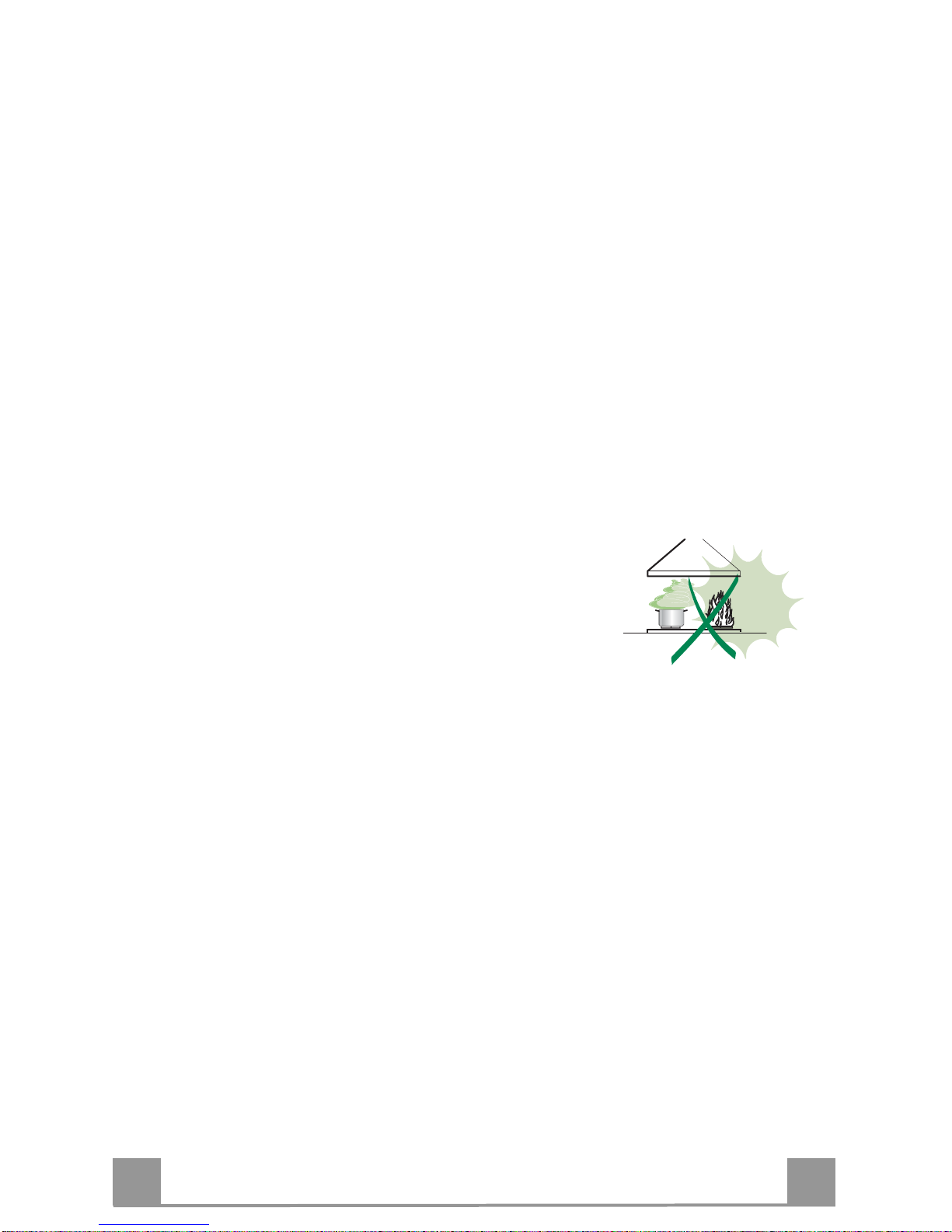
• Never leave high naked flames under the hood when it is in operation.
• Adjust the flame intensity to direct it onto the bottom of the pan only, making
sure that it does not engulf the sides.
• Deep fat fryers must be continuously monitored
during use: overheated oil can burst into flames.
• Do not flambè under the range hood; risk of fire.
• This appliance can be used by children aged from
8 years and above and persons with reduced
physical, sensory or mental capabilities or lack of
experience and knowledge if they have been given supervision or instruction
concerning use of the appliance in a safe way and understand the hazards
involved. Children shall not play with the appliance. Cleaning and user maintenance shall not be made by children without supervision.
Page 5

EN
5
5
• “CAUTION: Accessible parts may become hot when used with cooking ap-
pliances.”
MAINTENANCE
• Switch off or unplug the appliance from the mains supply before carrying out
any maintenance work.
• Clean and/or replace the Filters after the specified time period (Fire hazard).
• The Grease filters must be cleaned every 2 months of operation, or more
frequently for particularly heavy usage, and can be washed in a dishwasher.
• The Activated charcoal filter is not washable and cannot be regenerated,
and must be replaced approximately every 4 months of operation, or more
frequently for particularly heavy usage.
• Clean the hood using a damp cloth and a neutral liquid detergent.
The symbol on the product or on its packaging indicates that this product
may not be treated as household waste. Instead it shall be handed over to the
applicable collection point for the recycling of electrical and electronic equipment. By ensuring this product is disposed of correctly, you will help prevent
potential negative consequences for the environment and human health,
which could otherwise be caused by inappropriate waste handling of this
product. For more detailed information about recycling of this product, please
contact your local city office, your household waste disposal service or the
shop where you purchased the product.
Page 6

EN
6
6
CHARACTERISTICS
Dimensions
Page 7

EN
7
7
Components
Ref. Q.ty Product Components
1 1 Hood Canopy complete with: Controls, Light, Filters
2 1 Telescopic chimney, made up of:
2.1 1 Upper chimney
2.2 1 Lower chimney
7.1 1 Telescopic frame complete with Suction fan, made up
of:
7.1a 1 Upper frame
7.1b 1 Lower frame
9 1 Reduction flange ø 150-120 mm
14.1 2 Air Outlet Connector Extension
15 1 Air Outlet Connector
25 Hose clamps (not supplied)
Ref. Q.ty Installation Components
7.3 1 Air Outlet Connector fixing bracket
11 4 Wall plugs ø 10
12c 6 Screws 2.9 x 6.5
12e 2 Screws 2.9 x 9.5
12f 2 Screws M4 x 80
12g 4 Screws M6 x 80
12h 4 Screws 5.2 x 70
12q 4 Screws 3.5 x 9.5
21 1 Drilling template
22 8 Washers ø 6.4
23 4 Nuts M6
Q.ty Documentation
1 Instruction Manual
Page 8

EN
8
8
INSTALLATION
Drilling the Ceiling/shelf and fixing the frame
DRILLING THE CEILING/SHELF
• Use a plumb line to mark the centre of the hob on the ceiling/support shelf.
• Place the drilling template 21 provided on the ceiling/support shelf, making sure that the
template is in the correct position by lining up the axes of the template with those of the hob.
• Mark the centres of the holes in the template.
• Drill the holes at the points marked:
• For concrete ceilings, drill for plugs appropriate to the screw size.
• For hollow brick ceilings with wall thickness of 20 mm: drill ø 10 mm(immediately insert
the Dowels 11 supplied).
• For wooden beam ceilings, drill according to the wood screws used.
• For wooden shelf, drill ø 7 mm.
• For the power supply cable feed, drill ø 10 mm.
• For the air outlet (Ducted Version), drill according to the diameter of the external air exhaust duct connection.
• Insert two screws of the following type, crossing them and leaving 4-5 mm from the ceiling:
• For concrete ceilings, use the appropriate plugs for the screw size (not provided).
• for Cavity ceiling with inner space, with wall thickness of approx. 20 mm, Screws 12h,
supplied.
• For wooden beam ceilings, use 4 wood screws (not provided).
• For wooden shelf, use 4 screws 12g with washers 22 and nuts 23, provided.
Page 9

EN
9
9
Fixing the frame
• Loosen the two screws fastening the lower chimney and remove this from the lower frame.
• Loosen the two screws fastening the upper chimney and remove this from the upper frame.
If you wish to adjust the height of the frame, proceed as follows:
• Unfasten the metric screws joining the two columns, located at
the sides of the frame.
• Adjust the frame to the height required, then refit all the screws
removed as above.
• Insert the upper chimney stack from above, and leave it running free on the frame.
• Lift up the frame, fit the frame slots onto the screws up to the
slot end positions.
• Tighten the two screws and fasten the other two screws provided with the hood.
Before tightening the screws completely it is possible to adjust
the frame by turning it. Make sure that the screws do not come
out of their seats in the slotted holes.
• The frame mountings must be secure to withstand the weight
of the hood and any stresses caused by the occasional side
thrust applied to the device.
On completion, check that the base is stable, even if the frame
is subjected to bending.
• In all cases where the ceiling is not strong enough at the suspension point, the installer must provide strengthening using
suitable plates and backing pieces anchored to the structurally
sound parts.
2
2
1
1
Connections
DUCTED VERSION AIR EXHAUST SYSTEM
When installing the ducted version, connect the hood to the
chimney using either a flexible or rigid pipe ø 150 or 120 mm,
the choice of which is left to the installer.
• To install a ø 120 mm air exhaust connection, insert the reducer flange 9 on the hood body outlet.
• Fix the pipe in position using sufficient pipe clamps (not supplied).
• Remove any activated charcoal filters.
9
ø 150
ø 120
25
25
Page 10

EN
1
10
Air outlet – Recirculation Version
• Insert the Connector extensions 14.1 into the side of the Con-
nector 15.
• Insert the Connector 15 into the Support bracket 7.3 and fix it
with the screws.
• Fasten the Support bracket 7.3, fixing it to the upper part with
the Screws.
• Make sure that the Connector extensions outlet 14.1 is in correspondence with the Chimney openings both horizontally and
vertically.
• Join the Connector 15 to the Hood canopy outlet using a rigid
or flexible pipe ø¸150 mm, selection of which is at the discretion of the installation technician.
• Make sure that the Activated charcoal odour filter has been
fitted.
7.3
7.3
12c
12e
15
14.1
Flue assembly - Mounting the hood body
• Position the upper chimney section and fix the upper part to the
frame using the 2 screws 12c (2,9 x 6,5) provided.
• Similarly, position the lower chimney section and fix the
lower part to the frame using the 2 screws 12c (2,9 x 6,5) provided.
Before fixing the hood canopy to the frame:
• Screw the 2 screws 12f half way into the holes provided in the
sides of the bottom of the frame.
• Remove the grease filters from the hood canopy.
• Remove any activated charcoal filters.
• Lift the hood canopy and engage the screws 12f in the slots (A)
as far as they will go.
• Working from below, fix the hood canopy to the frame (B),
using the 4 screws 12q and 4 washers 22 provided, then tighten
all the screws securely.
Page 11

EN
1
11
ELECTRICAL CONNECTION
• Connect the hood to the mains through a two-pole
switch having a contact gap of at least 3 mm.
• Remove the grease filters (see paragraph Maintenance) being sure that the connector of the feeding
cable is correctly inserted in the socket placed on the
side of the fan.
• Connect the control connector Cmd.
• Connect the lights connector Lux.
• Connect the others 3 connectors inside the Hood respecting the colors.
• Remove the cap, pass all the wirings through the
opening and refit the cap.
• Fix all the wires in the clamps already fitted inside
the hood.
• For the recirculation version, fit the activated carbon
odour filter.
• Replace the grease filters.
Page 12

EN
1
12
USE
Control panel
Button Function Display
A Turns the suction motor on and off at speed one. Displays the set speed
B Decreases the working speed. Displays the set speed
C Increases the working speed. Displays the set speed
D Activates Intensive speed from any other speed,
including motor off. This speed is set to operate for 6
minutes, after which the system returns to the speed
that was set before. Suitable to deal with maximum
levels of cooking fumes.
Displays HI and the time remaining alternately, once a
second.
Press and hold the button for approximately 5
seconds, with all the loads turned off (Motor and
Lights), to turn the Activated Charcoal Filter alarm
on/off.
FC+Dot (Flashes twice)-Alarm Activated.
FC+Dot (Flashes once)-Alarm Deactivated.
E 24H function
Turns the motor on at speed one and effects one 10
minute extraction every hour.
Displays 24 and the dot at the bottom right flashes
once a second, while the motor is running.
It is disabled by pressing the button.
When the filters alarm is triggered, the alarm can be
reset by pressing and holding this button for
approximately 3 seconds.
These indications are only visible when the motor is
turned off.
FF flashes three times.
When the procedure terminates, the indication shown
previously turns off:
FG indicates the need to wash the metal grease filters.
The alarm is triggered after the Hood has been in
operation for 100 working hours.
FC indicates the need to change the activated charcoal
filters, and also to wash the metal grease filters. The
alarm is triggered after the Hood has been in operation
for 200 working hours.
F Delay function
Activate automatic switch-off with a 30’ delay.
Suitable to complete elimination of residual odours. It
can be activated from any position and is deactivated
by pressing the button or turning the motor off.
Displays the operating speed and the dot at the bottom
right flashes once a second.
Press and hold the button for approximately 5
seconds, with all the loads turned off (Motor and
Lights), to turn the Remote control on/off.
IR+Dot (Flashes twice)-Alarm Activated.
IR+Dot (Flashes once)-Alarm Deactivated.
G Turns the lighting system on and off at maximum
intensity.
-
Press and hold the button for approximately 2
seconds, turns the lighting system on and off in
Courtesy Light mode.
-
H Activates / Deactivates the Anti-condensation heating
elements (heating in 10 minutes).
The corresponding symbol flashes.
Page 13

EN
1
13
REMOTE CONTROL (OPTIONAL)
The appliance can be controlled using a remote control
powered by a 1.5 V carbon-zinc alkaline batteries of the
standard LR03-AAA type (not included).
• Do not place the remote control near to heat sources.
• Used batteries must be disposed of in the proper
manner.
Remote control panel
Mot
or Motor On / Off.
Decreases
the working speed each time it is pressed.
Increases the
working speed each time it is pressed.
Intensive Brief pressure: Act
ivates/Deactivates the Intensive function.
Anti-co
ndensation
Long pressure: Activates/Deactivates the Anti-condensation
heating elements.
24H
/ Delay
Brief pressure: Activates/Deactivates the Delay function:
automatic switch-off with a 30’ delay. The display shows the
operating speed and the dot at the bottom right flashes once a
second.
Press and hold for 2 seconds to Activate/Deactivate the 24h
function: this starts the motor at speed one and allows suction for
10 minutes every hour. The display shows the number 24 and the
dot at the bottom right flashes once a second.
Light
Brief pressure: Lig
hts On / Off.
Pressed for 2 Seconds: Courtesy lights On / Off.
Page 14

EN
1
14
MAINTENANCE
Opening Panel
• Open the Panel by pulling it.
• Clean the outside with a damp cloth and neutral detergent.
• Clean the inside using a damp cloth and neutral detergent; do
not use wet cloths or sponges, or jets of water; do not use
abrasive substances.
Metal grease filters
They can be washed in the dishwasher, and need to be cleaned
whenever the FG sign appears on the display or at least once
every 2 months use, or more frequently if use is particularly
intensive.
Resetting the alarm signal
• Turn the Lights and the Suction motor off, then disable the 24h
function, if enabled.
• Press button E (see the paragraph on Use).
Cleaning the Filters
• Open the Comfort panels by pulling on the recess.
• Remove the Filters one at a time, pushing them towards the
back of the unit and at the same time pulling downward.
• Wash the Filters without bending them, and leave them to dry
completely before replacing (If the surface of the filter changes
colour as time goes by, this will have absolutely no effect on
the efficiency of the filter itself.)
• Replace, taking care to ensure that the handle faces forwards.
• Close the Comfort panels.
Page 15

EN
1
15
Activated Charcoal Filter (Recirculation Version)
It cannot be washed or regenerated, and must be changed when the FC symbol on the display
appears, or at least once every 4 months. The Alarm signal, if it has been activated, only
appears when the Suction motor is turned on.
Activating the alarm signal
• In Recirculation Version Hoods, the Filter Saturation Alarm must be activated on
installation or at a later date.
• Turn the Lights and the Suction Motor off.
• Press D and hold for approximately 5 Seconds:
• The message FC+Puntino flashes twice, A.C. Filter saturation alarm ACTIVATED
• The message FC+Puntino flashes once, A.C. Filter saturation alarm DEACTIVATED
CHANGING THE ACTIVATED CHARCOAL FILTER
Resetting the alarm signal
• Turn the Lights and the Suction motor off, then disable the 24h
function, if enabled.
• Press button E (see the paragraph on Use).
Changing the Filter
• Open the Comfort panels by pulling on the recess.
• Remove the Metal grease filters.
• Remove the saturated charcoal filter by releasing the fixing
hooks.
• Fit the new filter and fasten it in its correct position.
• Replace the Metal grease filters.
• Close the Comfort panels.
Lighting unit
Warning: This appliance is fitted with a white LED lamp classed
as 1M according to EN 60825-1: 1994 + A1:2002 + A2:2001
standards; maximum optical power emitted @439nm: 7µW. Do
not look directly at the light through optical devices (binoculars,
magnifying glasses…).
• For replacement contact technical support. ("To purchase contact technical support")
Page 16

991.0351.106_ver6 - 150422
Fr
anke S.p.a.
Via Pignolini,2
37019 Peschiera del Garda (VR)
www.franke.it
 Loading...