

Franke FGAS/3 E FX 1000 CE XS WM, FGAS/3EFX 1400 CE XS WM, FGAS/3 FX 1400 CE XS Instructions For Use And Installation
Page 1
Instructions for use and installation
Cooker Hood
Istruzioni per l’uso e l’installazione
Cappa
Instrucciones de instalacion e utilizacion
Campana
Bedienungsanleitung und Einrichtung
Dunstabzugshaube
GB
IT
E
DE
Instructies voor het gebruik en installeren
Dampkap
NL
Galaxy Slim 3 FX
Mode d’emploi et installation
Hotte de Cuisine
110.0263.116 FGAS/3 E FX 1000 CE XS WM
110.0263.117 FGAS/3EFX 1400 CE XS WM
110.0263.119 FGAS/3 E FX 1000 CE XS
110.0263.120 FGAS/3EFX 1400 CE XS
110.0278.393 FGAS/3 FX 1000 CE XS
110.0278.395 FGAS/3 FX 1400 CE XS
110.0278.394 FGAS/3 FX 1000 CE XS WM
110.0278.396 FGAS/3 FX 1400 CE XS WM
FR
Page 2

F SOMMAIRE
RACCORDEMENT ÉLECTRIQUE
CONSEILS D’INSTALLATIONS
POSE DE L’APPAREIL
FONCTIONNEMENT
CONSEILS D’UTILISATIONS
ENTRETIEN
GARANTIE ET SERVICE APRÈS-VENTE
REMARQUES
D INHALT
NETZANSCHLUSS
MONTAGEHILFEN
MONTAGE DES GERÄTES
BETRIEB DES GERÄTES
NUTZUNG
WARTUNG UND REINIGUNG
GARANTIE UND KUNDENDIENST
WICHTIGE HINVEISE
E SUMARIO
CONEXION ELECTRICA
CONSEJOS DE INSTALACION
INSTALACION DEL APARATO
FUNCIONAMIENTO
CONSEJOS DE UTILIZACION
MANTENIMIENTO
GARANTIA Y ASSISTENCIA TECNICA
NOTA
GB CONTENTS
ELECTRICAL WIRING
INSTALLATION ADVICE
FITTING THE APPLIANCE
OPERATION
USEFUL HINTS
MAINTENANCE
GUARANTEE AND AFTER-SALES-SERVICES
REMARKS
I CONTENUTI
COLLEGAMENTO ELETTRICO
CONSIGLI DI INSTALLAZIONE
POSA DELL’ APPARECCHIO
FUNZIONAMENTO
CONSIGLI DI UTILIZZO
MANUTENZIONE
GARANZIA ED ASSISTENZA TECNICA
NOTE
NL INHOUD
ELECTRISCHE BEDRADING
MONTAGE AANWIJZING
AANSLUITEN VAN HET APPARAAT
FUNKTIONEREN
GEBRUIKSADVIES
ONDERHOUD
AFTER SALES SERVICE
OPMERKINGEN
Page 3
1
F
Nous vous remercions de la conance que vous nous avez accordée en choisissant un appareil de la
gamme FRANKE.
Celui-ci a fait l’objet de toute notre attention dans sa conception et sa réalisation.
An qu’il vous donne entière satisfaction, nous vous recommandons de lire avec attention cette notice qui
vous expliquera comment l’installer, l’utiliser et l’entretenir dans les meilleures conditions.
La présente notice d’emploi vaut pour plusieurs versions de l’appareil. Elle peut contenir des descriptions
d’accessoires ne gurant pas dans votre appareil.
Avec ce kit, il est possible d’installer à distance le moteur de la hotte à l’intérieur de l’habitation. L’installation
devra être effectuée par un personnel qualié en accord avec les directives réglementaires édictées par les
services compétents en matière de renouvellement d’air. Le fabricant ne pourra être tenu pour responsable
des dégâts résultant d’une installation incorrecte ou de sa non-conformité.
1 RACCORDEMENT ÉLECTRIQUE.
• La hotte est équipée d’un cordon d’alimentation de type HO5VVF 3 x 0,75 mm² comportant une
che normalisée 10/16 A avec système de mise à la terre.
Mode de protection : classe I. Tension d’alimentation : 220-240 V mono - 50Hz / 220 V - 60Hz.
Vérier que la tension du secteur est identique aux valeurs indiquées sur la plaque signalétique à
l’intérieur de la hotte
• Si la hotte est raccordée directement sur le réseau sans sa che, un interrupteur omnipolaire avec
une ouverture de contact de 3 mm doit être installé avant la hotte. Le l de terre (Jaune / vert) ne doit
pas être interrompu par cet interrupteur.
2 CONSEILS D’INSTALLATION.
• Nous vous conseillons une hauteur de pose maximale de 1,5 m au-dessus du plan de cuisson.
Toutefois, il est formellement interdit d’installer toute hotte ou groupe d’aspiration à une distance infé-
rieure à 0,65 m du plan de travail (risque d’inammation des ltres). La fumée doit monter naturellement
vers la zone de captation.
• Respecter le diamètre de sortie de l’appareil : la hotte ne doit en aucun cas être raccordée à un
conduit de ventilation mécanique contrôlée (V.M.C.).
• Lorsqu’on évacue l’air vicié dans un conduit d’évacuation, veiller à ce que celui-ci ne soit pas déjà
exploité à véhiculer des gaz ou fumées provenant d’appareils alimentés par une énergie autre qu’électrique.
• Positionner le plan de cuisson au plus près de l’évacuation et éviter la formation de coudes sur la
gaine, an de réduire au maximum les pertes de charges.
• Dans tous les cas d’installation, veiller au bon renouvellement d’air de la cuisine. Penser à effectuer une ou des entrées d’air par une grille de section égale ou supérieure au diamètre du tuyau
d’évacuation, an de ne pas mettre la cuisine en dépression.
• Prévoir une aération sufsante lorsqu’un appareil de cuisson ou autre utilise simultanément l’air
ambiant de la pièce où est installée la hotte.
• La dépression maximum crée dans la pièce doit être inférieur à 0.04 mbar, ce qui évite un retour de
gaz de combustion.
• L’appareil doit être positionné de telle façon que la che d’alimentation soit accessible.
• Cet appareil ne doit pas être utilisé par des personnes (y compris les enfants) ayant des capacités
Page 4
2
F
psychiques, sensorielles ou mentales réduites, ni par des personnes n’ayant pas l’expérience et la
connaissance de ce type d’appareils, à moins d’être sous le contrôle et la formation de personnes responsables de leur sécurité.
Les enfants doivent être surveillés pour s’assurer qu’ils ne jouent pas avec l’appareil.
3 POSE DE L’APPAREIL.
Montage et raccordement doivent être réalisés par un installateur* qualié.
(*) Le non-respect de cette condition entraîne la suppression de la garantie du constructeur et
tout recours en cas d’accident.
Attention: prendre bien soin d’employer les chevilles adaptées au support, se renseigner au près
des fabricants, effectuer un scellement si nécessaire. La société décline toute responsabilité en
cas d’accrochage défectueux dû au perçage et chevillage au plafond.
1) Ouvrir le colis de la hotte.
• FIXATION PAR LE CHASSIS :
PERCAGE DU PLAFOND
2) A l’aide d’un l à plomb reporter au plafond le centre du plan de cuisson. Tracer les axes parallèlement
au plan de cuisson (Fig. 1).
3) Réaliser la découpe d'encastrement dans le faux-plafond (Fig 2a).
4) Tracer les centres des différents perçages à effectuer sur le plafond. (Fig 2b)
5) Percer le plafond à l’endroit de la pose, dont un trou de Ø 40 qui permet le passage de l’alimentation suivant la Fig. 2b. Si le plafond est en béton, employer 4 chevilles en fonte pour Ø 10, exclure les
chevilles en plastique. Si celui-ci vous semble de solidité douteuse, n’hésitez pas à le renforcer dans les
combles (Fig. 3). Fixer solidement la boîte moteur (Fig.4) : 4 positions à 90°.
6) Ajuster la hauteur de la boîte moteur: 20 mm de réglage (Fig. 5).
7) Ouvrir le déecteur du plateau (Fig. 6 Rep. 12) par: pousser / dévérrouiller (Fig 14) .
8) Enlever les ltres.
• RACCORDEMENT
• Version Evacuation Extérieure :
a- Mettre le clapet anti retour C sur la sortie de l’appareil (Rep. 6) et raccorder le tuyau exible
à l’évacuation extérieure et à la sortie de l’appareil. Fixer l’ensemble à l’aide de colliers ou de ruban
adhésif appropriés (Fig. 8).
b- Raccorder électriquement le moteur (Voir paragraphe Raccordement Electrique).
c- Fixer le corps de la hotte (Fig.10).
Attention : Cette phase du montage doit être réalisée à 2 personnes.
d- Raccorder le connecteur du moteur sur la hotte (Fig.7).
e- Vérier les connecteurs du moteur (Fig.9).
f- Vérier le bon fonctionnement de l’éclairage, du moteur et du changement des vitesses
d’aspiration.
g- Mettre en place les ltres et refermer le déecteur du plateau.
• Version Recyclage :
a- Prévoir un retour dans la cuisine (Fig. 11).
b- Installer un tuyau de diamètre approprié (Non fourni) entre la sortie de l’appareil (Rep. 6) et
ce retour. Fixer l’ensemble à l’aide de colliers ou de ruban adhésif appropriés (Fig. 12).
c- Raccorder électriquement le moteur (Voir paragraphe Raccordement Electrique).
d- Fixer le corps de la hotte (Fig.10).
Page 5
3
F
Attention : Cette phase du montage doit être réalisée à 2 personnes.
e- Raccorder le connecteur du moteur sur la hotte (Fig.7).
f- Vérier les connecteurs du moteur (Fig.9).
g- Vérier le bon fonctionnement de l’éclairage, du moteur et du changement des vitesses
d’aspiration.
h- Placer les cartouches à charbon actif sur le moteur (Fig. 13)
i- Mettre en place les ltres et refermer le réecteur du plateau.
• CLIPPAGE SUR LE FAUX-PLAFOND :
2) A l’aide d’un l à plomb reporter au plafond le centre du plan de cuisson. Tracer les axes parallèlement
au plan de cuisson (Fig. 1).
3) Réaliser la découpe d'encastrement dans le faux-plafond (Fig 2a).
4) Enlever les caches des points lumineux (Fig. 15).
5) Dévisser les vis des clips en fonction de l'épaisseur du faux-plafond (Fig. 16). Si le faux-plafond vous
semble de solidité douteuse n’hésitez pas à le renforcer (Fig. 17). Pour les faux-plafond en MDF de 18
mm, 4 cales de compensation ( 2 mm d'épaisseur) sont fournies avec l'appareil.
6) Ouvrir le déecteur du plateau (Fig. 6 Rep. 12) par: pousser / dévérrouiller (Fig 14) .
7) Enlever les ltres.
• RACCORDEMENT
• Version Evacuation Extérieure :
a- Mettre le clapet anti retour C sur la sortie de l’appareil (Rep. 6) et raccorder le tuyau exible
à l’évacuation extérieure et à la sortie de l’appareil. Fixer l’ensemble à l’aide de colliers ou de ruban
adhésif appropriés (Fig. 8).
b- Raccorder électriquement le moteur (Voir paragraphe Raccordement Electrique).
c- Fixer le corps de la hotte (Fig.10) ou clipsé l'appareil sur le faux-plafond (Fig. 15), resserer
les vis (Fig. 16) et remettre les caches lumières .
Attention : Cette phase du montage doit être réalisée à 2 personnes.
d- Raccorder le connecteur du moteur sur la hotte (Fig.7).
e- Vérier les connecteurs du moteur (Fig.9).
f- Vérier le bon fonctionnement de l’éclairage, du moteur et du changement des vitesses
d’aspiration.
g- Mettre en place les ltres et refermer le déecteur du plateau.
• Version Recyclage :
a- Prévoir un retour dans la cuisine (Fig. 11).
b- Installer un tuyau de diamètre approprié (Non fourni) entre la sortie de l’appareil (Rep. 6) et
ce retour. Fixer l’ensemble à l’aide de colliers ou de ruban adhésif appropriés (Fig. 12).
c- Raccorder électriquement le moteur (Voir paragraphe Raccordement Electrique).
d- Fixer le corps de la hotte (Fig.10) ou clipsé l'appareil sur le faux-plafond (Fig. 15), resserer
les vis (Fig. 16) et remettre les caches lumières .
Attention : Cette phase du montage doit être réalisée à 2 personnes.
e- Raccorder le connecteur du moteur sur la hotte (Fig.7).
f- Vérier les connecteurs du moteur (Fig.9).
g- Vérier le bon fonctionnement de l’éclairage, du moteur et du changement des vitesses
d’aspiration.
h- Placer les cartouches à charbon actif sur le moteur (Fig. 13)
i- Mettre en place les ltres et refermer le réecteur du plateau.
Page 6

4
4 FONCTIONNEMENT
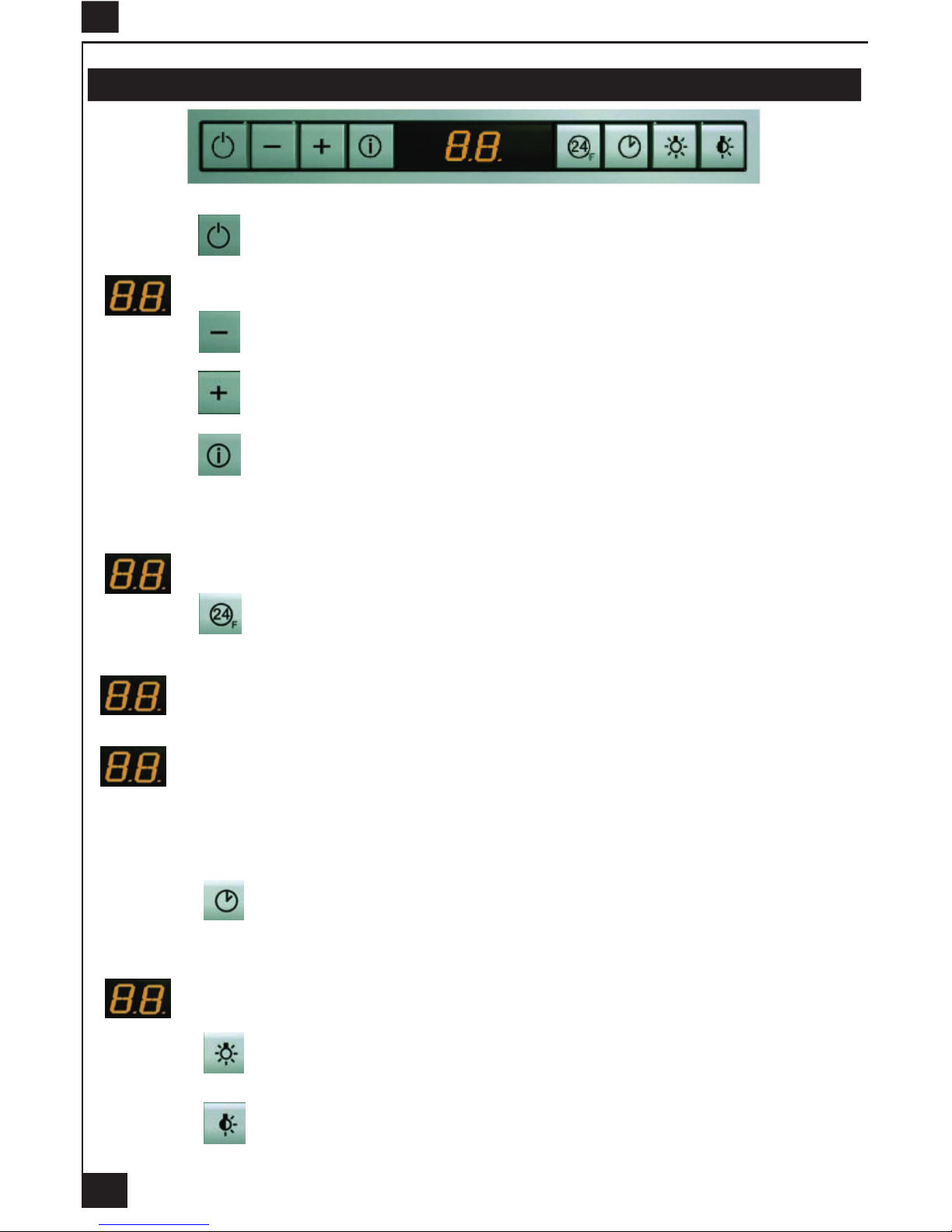
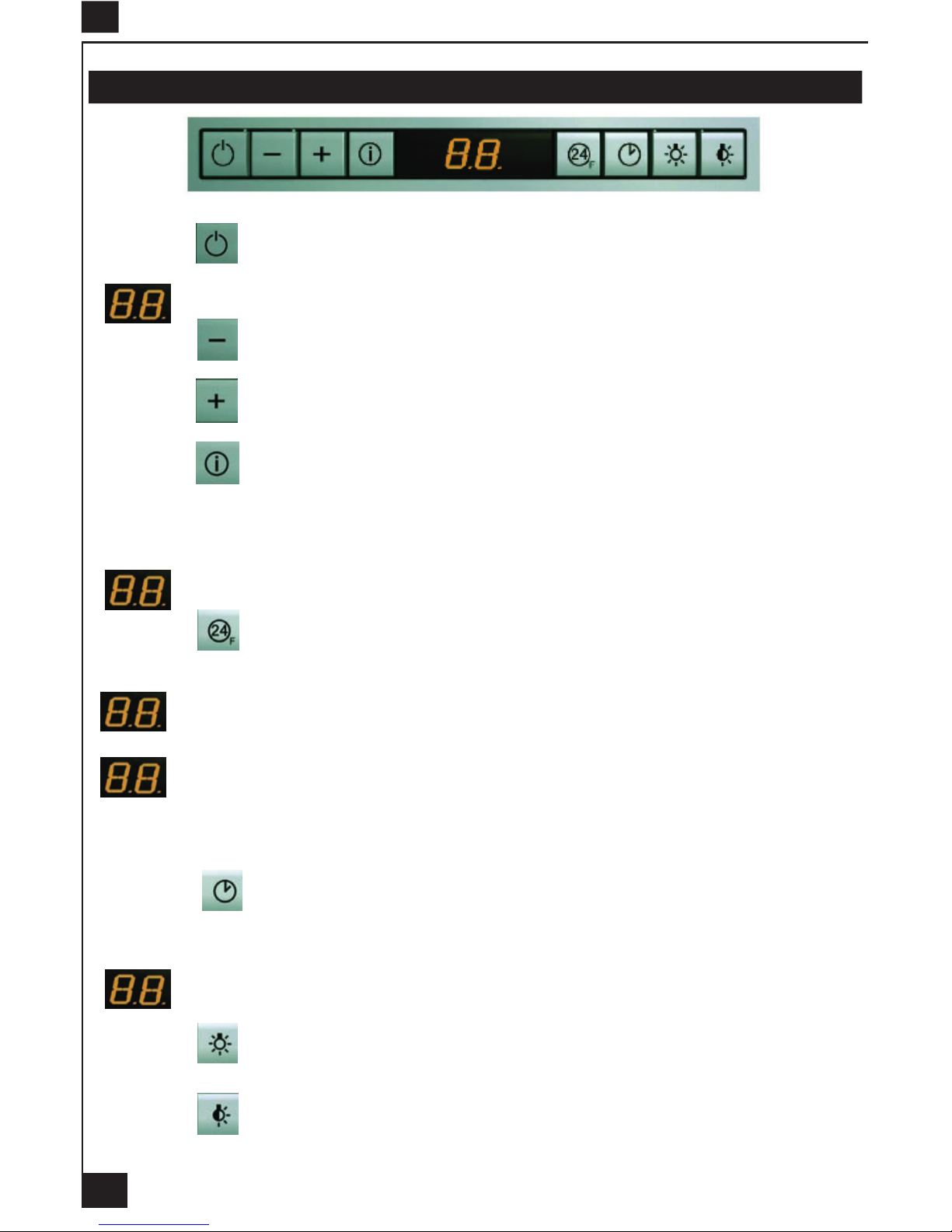
Tableau de commande
Touche : Marche / Arrêt
Allume et éteint le moteur d'aspiration à la dernière vitesse utilisée.
Afche la vitesse choisie.
Touche : Réglage vitesse
Diminue la vitesse de service.
Touche
: Réglage vitesse
Augmente la vitesse de service.
Touche
: Vitesse intensive
Active la vitesse intensive à partir de n'importe quelle vitesse, même du moteur arrêter. cette vitesse
est programmée pour durer 10 minutes, après quoi le système retourne à la vitesse réglée au préalable. Sert à faire face à une quantité maximale de fumées de cuisson.
Afche HI et le point bas à droite clignote une fois par seconde.
Touche
: Renouvellement d'air
Active le moteur à une vitesse permettant une aspiration de100 m3/h pendant 10 minutes toutes les
heures, puis le moteur s'arrête.
Afche 24 et le point en bas à droite clignote, quand le moteur fonctionne.
Quand l'alarme ltres est déclenchée, appuyer sur cette touche pendant 3 secondes environ pour
remettre l'alarme à l'état initial. Ces indications sont visibles uniquement quand le moteur est éteint.
En n de procédure, le signal afché précédemment s'éteint :
FF indique qu'il faut laver les ltres à graisse métalliques. L'alarme se déclenche après 100
heures de fonctionnement effectif de la hotte.
EF indique qu'il faut remplacer les ltres au charbon actif et laver les ltres à graisse métalliques. L'alarme se déclenche après 200 heures de fonctionnement effectif de la hotte.
Touche
: Arrêt différé 30 minutes
Active l'arrêt automatique retardé de 30 minutes. Utile pour achever d'éliminer toute odeur résiduelle.
S'active depuis toutes les positions et se désactive en appuyant sur la touche ou en éteignant le
moteur.
Afche tour à tour la vitesse de service et le temps restant avant l'arrêt de la hotte. le point
en bas à droite clignote.
Touche
: Lumière
Allume et éteint l'éclairage.
Touche
: Lumière
Allume et éteint le second groupe d'éclairage (Eclairage d'ambiance).
F
Page 7
5
5 CONSEILS D’UTILISATION.
• Pour obtenir une efcacité maximum d’absorption des fumées ou des vapeurs, faire fonctionner
l’appareil 5 minutes environ avant et après la cuisson des aliments; La première vitesse est conseillée
pour les cuissons à feu doux et pour les sauces. La deuxième pour les cuissons soutenues, grillades et
friteuses. La troisième est indiquée pour les cuissons à forte émanation de graisses et vapeur.
• IMPORTANT . NE JAMAIS FLAMBER DE METS AU DESSOUS DE L’APPAREIL
Ne laissez jamais de ammes libres sous la hotte en fonctionnement.
• Les fritures nécessitent une surveillance permanente, l’huile surchauffée pouvant s’enammer.
6 ENTRETIEN.
Déconnecter le câble d’alimentation pour toute intervention électrique.
L’appareil a été conçu pour faciliter au maximum les opérations d’entretien, synonyme de bon fonction-
nement et rendement de l’appareil dans le temps.
• Nettoyage des ltres métalliques.
Il est indispensable de procéder à un NETTOYAGE PÉRIODIQUE de ces ltres à la main (avec un déter-
gent liquide à l’eau tiède et rinçage) ou au lave- vaisselle (tous les deux mois environ pour une utilisation
normale).
• Carrosserie.
Nettoyer régulièrement celle-ci en utilisant des produits détergents, non abrasifs et une éponge légèrement
humide. N’utilisez jamais d’éponges ou de chiffons trempés
N’introduisez aucun objet, ni les mains dans l’ouverture servant à l’évacuation de l’air
• Conduit d’évacuation.
Vérier tous les 6 mois le bon écoulement de l’air vicié.
Observer les prescriptions réglementaires locales concernant l’évacuation de l’air vicié.
• Éclairage.
Avant toute intervention sur l’appareil, mettre l’interrupteur d’allumage des lampes en position éteinte.
Ne pas dépasser la puissance prescrite et ne pas changer de type de lampe.
• Télécommande.
Attention, la télécommande doit être équipée de piles alcalines standards : LR003-AAA, 1.5V.
Ces piles devraient assurer un usage optimum de longue durée et doivent être positionnées
correc-tement, elles peuvent exploser si elles sont endommagées ou exposées à la chaleur. Ne
pas les jeter dans le feu. An de préserver l’environnement, merci de déposer ces piles dans un
conteneur approprié.
7 GARANTIE ET SERVICE APRÈS-VENTE.
• En cas d’anomalie de fonctionnement, prévenez votre installateur qui devra vérier l’appareil et son
raccordement.
• Dans le cas où un composant électrique viendrait à être endommagé, celui-ci ne peut être remplacé
que par un atelier de réparation reconnu par le fabricant, car des outils spéciaux sont nécessaires.
• Débrancher complètement l’appareil.
• Exigez toujours l’utilisation de pièces de rechange d’origine. La non observation de cette prescription
peut compromettre la sécurité de l’appareil.
• Lors de la commande de pièces détachées, rappeler le numéro de l’appareil inscrit sur la plaque
signalétique située à l’intérieur de la hotte.
• Seule la facture d’achat de l’appareil fera foi pour l’application de la garantie contractuelle.
Cette garantie ne couvre pas les consommables comme :
F
Page 8
6
- L’éclairage : lampes incandescentes, halogènes ...
- Les ltres.
8 REMARQUES.
Cet équipement est conforme à la norme européenne sur la basse tension 2006/95/CE relative à la
sécurité électrique et aux normes européennes: 2004/108/CE relative à la compatibilité électromagnétique
et 93/68 relative au marquage CE.
Lorsque ce symbole
d’une poubelle à roue barrée est attaché à un produit, cela signie que le
produit est couvert par la Directive Européenne 2002/96/EC. Votre produit est conçu et fabriqué avec
des matériaux et des composants de haute qualité, qui peuvent être recyclés et utilisés de nouveau.
Veuillez vous informer du système local de séparation des déchets électriques et électroniques. Veuillez
agir selon les règles locales et ne pas jeter vos produits usagés avec les déchets domestiques usuels.
Jeter correctement votre produit usagé aidera à prévenir les conséquences négatives potentielles contre
l’environnement et la santé humaine.
F
Page 9
7
GB
Thank you for buying a FRANKE product which has been manufactured to the highest quality standards
to meet your requirements.
We recommend you carefully read this booklet in which you will nd instructions for installation, hints for
use and maintenance.
The Instructions for Use apply to several versions of this appliance. Accordingly, you may nd descriptions of individual features that do not apply to your specic appliance.
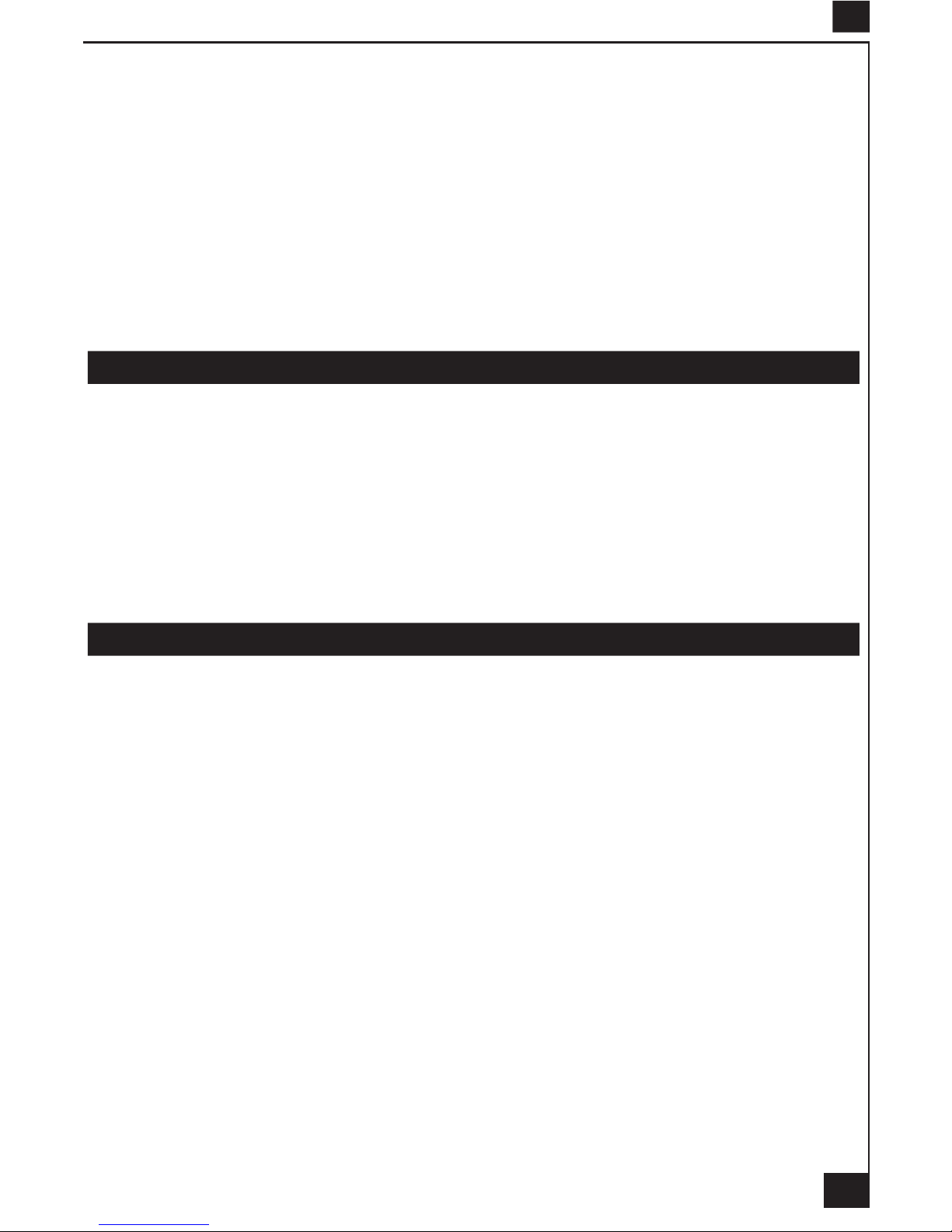
With this kit it is possible to place the blower of the kitchen hood to a remote position inside the house.
Installation of the kit must be carried out by qualied staff, following all the rules given by the relevant
authorities concerning the exhaust air ducting. The manufacturer will not be liable for any damages
resulting from incorrect or from improper installation.
1 ELECTRICAL
• This cooker hood is tted with a 3-core mains cable with a standard 10/16A earthed plug.
• Alternatively the hood can be connected to the mains supply via a double-pole switch having 3mm
minimum contact gap on each pole.
• Before connecting to the mains supply ensure that the mains voltage corresponds to the voltage on
the rating plate inside the cooker hood.
• Technical Specication: Voltage 220-240 V, single phase ~ 50 Hz / 220 V - 60Hz.
2 INSTALLATION ADVICE
• Ensure the cooker hood is tted in compliance with the recommended xing heights: 150cm maximum.
• To ensure the safe operation of this cooker hood, we recommend that the hood should not be tted
below 65cm (for electric) or (70cm for gas) the measurements taken from the surface of the cooking
appliance to the underside of the cooker hood.
• It is a possible re risk if the hood is not sited as recommended.
• To ensure the best results, the cooking fumes should be able to rise naturally towards the inlet grilles
on the underside of the cooker hood and the cooker hood should be positioned away from doors and
windows, which will create turbulence.
• Ducting
• If the room where the hood is to be used contains a fuel-burning appliance such as a central heating
boiler then its ue must be of the room sealed or balanced ue type.
• If other types of ue or appliances are tted ensure that there is an adequate supply of fresh air to
the room. Ensure the kitchen is tted with an airbrick, which should have a cross-sectional measurement
equivalent to the diameter of the ducting being tted, if not larger.
• The ducting system for this cooker hood must not be connected to any existing ventilation system,
which is being used for any other purposes or to a mechanically controlled ventilation ducting.
• The ducting used must be made from re retardant materials and the correct diameter must be used,
as incorrect sized ducting will affect the performance of this cooker hood.
• When the cooker hood is used in conjunction with other appliances supplied with energy other than
electricity, the negative pressure in the room must not exceed 0.04 mbar to prevent the fumes from
combustion being drawn back into the room.
• The appliance is for domestic use only and should not be operated by children or people who are
inrm without supervision.
• This appliance must be positioned so that the wall socket is accessible.
• This appliance is not intended for use by persons (including children) with reduced physical, sensory
or mental capabilities, or lack of experience and knowledge, unless they have been given supervision or
instruction concerning use of the appliance by a person responsible for their safety.
Children should be supervised to ensure that they do not play with the appliance.
3 FITTING
Any permanent electrical installation must comply with the latest regulations concerning this type of installation and a qualied electrician must carry out the work. Non-compliance could cause serious accidents
Page 10
8
GB
or injury and would deem the manufacturers guarantee null and void.
IMPORTANT - The wires in this mains lead are coloured in accordance with the following code :
green / yellow : earth blue : neutral brown : live
As the colours of the wires in the mains lead of this appliance may not correspond with the coloured
markings identifying the terminals in your plug, proceed as follows.
- The wire which is coloured green and yellow must be connected to the terminal in the plug which is
marked with the letter E or by the earth symbol
or coloured green or green and yellow.
- The wire which is coloured blue must be connected to the terminal which is marked with the letter N
or coloured black.
- The wire which is coloured brown must be connected to the terminal which is marked with the letter
L or coloured red.
ATTENTION: Do not forget to use adequate plugs to the support brackets. Enquire after the manufacturers. Do an embedding if necessary. The manufacturer accepts no responsibility in case of a
faulty hanging due to the drilling and the setting up of plugs in the ceiling.
1) Unpack the hood parcel.
• FIXING BY THE STRUCTURE : LAYING OUT BEFORE FITTING THE HOOD
2) Mark the centre of the cooking appliance onto the ceiling with a plumb line. Draw the horizontal axes
running parallel to the stove top onto the ceiling as illustrated Fig. 1.
3) To carry out the cutting of embedding in the suspended ceiling (Fig 2a).
4) To mark the centers of different drillings to be carried out on the ceiling. (Fig 2b)
5) Drill the different holes with the appropriate masonry bit :
- The cut-out for the ducting Ø 150 mm in the extraction
mode when ducting runs through the ceiling.
- The mains supply cords.
- The 4 xing holes for Ø 10 mm nuts and bolts.
When xing the cooker hood to a plasterboard ceiling ensure it is reinforced as illustrated in Fig. 3 and
attach using four Ø10mm nuts and bolts; ensuring the bolts as sleeved between the plasterboard and the
joist supports to prevent the ceiling being damaged when the bolts are tightened up.
If the ceiling is concrete, use eight Ø 10 mm steel rawl bolts. Plastic rawl plugs must not be used. Fit the
motor housing (Fig. 4): 4 positions with 90°.
6) To adjust the height of the motor housing: 20 mm of adjustment (Fig. 5).
7) Open the deector ( Fig. 6 Rep. 12) by pushing / unlocking (Fig. 14).
8) To remove the metal lters.
• DUCTING
The hood is more effective when used in the extraction mode (ducted to the outside). When the cooker
hood is ducted to the outside, charcoal lters are not required.
The ducting used must be 150 mm (6 INS), rigid circular pipe and must be manufactured from re retardant material, produced to BS.476 or DIN 4102-B1. Wherever possible utilise rigid circular pipe which has
a smooth interior, rather than the expanding concertina type ducting.
Maximum length of ducting run:
- 4 metres with 1 x 90° bend.
- 3 metres with 2 x 90° bends.
- 2 metres with 3 x 90° bends.
The above assumes our 150 mm (6 INS) ducting is being installed. Please note ducting components and
ducting kits are optional accessories and have to be ordered, they are not automatically supplied with the
chimney hood.
IN THE EXTRACTION MODE:
a- Fit the non-return backow aps C over the round outlet item 6 on top of the canopy while pressing
down until they snap into position, and then connect the ducting 150mm (6 INS) and secure the connections with appropriate clamping rings or adhesive tape (Fig. 8).
b- Make the electrical connection of the motor as described in the section titled ELECTRICAL.
c- Place the canopy under the motor housing and x it with the screws provided as illustrated in Fig. 10.
Attention: 2 persons are necessary to secure this operation..
d- Connect the electrical plug of the motor cord on the body hood (Fig.7).
Page 11

9
GB
e- Check the connectors of the motor (Fig 9).
f- Test the lights and the fan motor.
g- Fit the metal grease lters and close the deector.
IN THE RECIRCULATION MODE:
a- To carry out an inlet for recycling air in the kitchen (Fig.11).
b- Connect the ducting 150mm (6 INS) not provided between motors item 6 and the recirculation spigot
and secure the connections with appropriate clamping rings or adhesive tape (Fig. 12).
c- Make the electrical connection of the motor as described in the section titled ELECTRICAL.
d- Place the canopy under the motor housing and x it with the crews provided as illustrated in Fig. 10.
Attention: 2 persons are necessary to secure this operation.
e- Connect the electrical plug of the motor cord on the body hood (Fig.7).
f- Check the connectors of the motor (Fig 9).
g- Test the lights and the fan motor.
h- Fit the charcoal lter onto the inlets of the motor (Fig. 13).
i- Fit the metal grease lters and close the deector.
• CLIPPAGE ON THE FALSE CEILING
2) Mark the centre of the cooking appliance onto the ceiling with a plumb line. Draw the horizontal axes
running parallel to the stove top onto the ceiling as illustrated Fig. 1.
3) To carry out the cutting of embedding in the suspended ceiling (Fig 2a).
4) To remove the lighting front panel (Fig. 15).
5) To unscrew the screws of the clips according to the thickness of the false ceiling (Fig. 16). When xing
the cooker hood to a plasterboard ceiling ensure it is reinforced as illustrated in Fig. 17. For the false
ceiling in MDF of 18 mm, 4 holds of compensation (2 mm thickness) are provided with the hood.
6) Open the deector ( Fig. 6 Rep. 12) by pushing / unlocking (Fig. 14).
7) To remove the metal lters.
IN THE EXTRACTION MODE:
a- Fit the non-return backow aps C over the round outlet item 6 on top of the canopy while pressing
down until they snap into position, and then connect the ducting 150mm (6 INS) and secure the connections with appropriate clamping rings or adhesive tape (Fig. 8).
b- Make the electrical connection of the motor as described in the section titled ELECTRICAL.
c- Place the canopy under the motor housing and x it with the screws provided as illustrated in Fig. 10
or clip the hood on the false ceiling (Fig. 15), to tighten the screws (Fig. 16) and to t back the lighing
front panel.
Attention: 2 persons are necessary to secure this operation..
d- Connect the electrical plug of the motor cord on the body hood (Fig.7).
e- Check the connectors of the motor (Fig 9).
f- Test the lights and the fan motor.
g- Fit the metal grease lters and close the deector.
IN THE RECIRCULATION MODE:
a- To carry out an inlet for recycling air in the kitchen (Fig.11).
b- Connect the ducting 150mm (6 INS) not provided between motors item 6 and the recirculation spigot
and secure the connections with appropriate clamping rings or adhesive tape (Fig. 12).
c- Make the electrical connection of the motor as described in the section titled ELECTRICAL.
d- Place the canopy under the motor housing and x it with the screws provided as illustrated in Fig. 10
or clip the hood on the false ceiling (Fig. 15), to tighten the screws (Fig. 16) and to t back the lighing
front panel.
Attention: 2 persons are necessary to secure this operation.
e- Connect the electrical plug of the motor cord on the body hood (Fig.7).
f- Check the connectors of the motor (Fig 9).
g- Test the lights and the fan motor.
h- Fit the charcoal lter onto the inlets of the motor (Fig. 13).
i- Fit the metal grease lters and close the deector.
Page 12
10
4 OPERATION
Control board
Key : On / Off
Switches the extractor motor on and off at the latest selected speed.
Indicates the selected speed.
Key
: Speed control
Decreases the suction speed.
Key
: Speed control
Increases the suction speed.
Key : Intensive speed
By pressing this key it is possible to activate the intensive speed from any previously se-lected speed.
The intensive speed can be acti-vated even when the motor is OFF. This speed has been timed at 10
minutes. After that time the system activates automatically the latest selected speed. This function is
suitable for cooking conditions when vapours and smells are of the utmost emission.
HI appears. The spot down on the right side ashes once a second.
Key
: Air Renewing
By pressing this key it is possible to set up the motor to a suction speed at 100 m3/h lasting 10 minutes every hour. After this the motor switches off automatically.
Indicates the 24-function. The spot down on the right side ashes and the motor is on.
When the lter saturation is going on it is pos-sible to reset the alarm by pressing this key
for about 3 seconds. The indication is visible only when the motor is off.
Once the process is nished the previous indi-cation disappears:
FF Indicates that the metal grease lters saturation alarm has been triggered, and the lters
need to be washed. The alarm is triggered after 100 working hours.
EF Indicates that the charcoal lter satura-tion alarm has been triggered, and the l-ter has
to be replaced; the metal grease lters must also be washed. The charcoal lter is triggered after 200
working hours.
Key : Stop delay 30 minutes
By pressing this key it is possible to set the delayed shutdown of the appliance to 30 min-utes. This
function is suitable for a complete elimination of the residual smells. It can be activated at any position,
and it is deactivated by pressing the key again or by switching off the motor.
Indicates alternately the selected speed of the hood and the time left before the hood shut-
down. The spot down on the right side ashes.
Key
: Lighting
Turns light on and off .
Key
: Lighting
Turns the second light unit on and off (ambient lighting).
GB
Page 13
11
5 USEFUL HINTS
• To obtain the best performance we recommend you to switch ‘ON’ the cooker hood a few minutes (in
the boost setting) before you start cooking and you should leave it running for approximately 15 minutes
after nishing.
• IMPORTANT: NEVER DO FLAMBÉ COOKING UNDER THIS COOKER HOOD
• Do not leave frying pans unattended during use as over-heated fat and oil might catch re.
• Do not leave naked ames under this cooker hood.
• Switch ‘OFF’ the electric and gas before removing pots and pans.
• Ensure heating areas on your hotplate are covered with pots and pans when using the hotplate
and cooker hood simultaneously.
6 MAINTENANCE
Before carrying out any maintenance or cleaning isolate the cooker hood from the mains supply.
The cooker hood must be kept clean; a build up of fat or grease may cause a re hazard.
Casing
• Wipe the cooker hood frequently with a clean cloth, which has been immersed in warm water containing a mild detergent and wrung out.
• Never use excessive amounts of water when cleaning particularly around the control panel.
• Never use scouring pads or abrasive cleaners.
• Always wear protective gloves when cleaning the cooker hood.
Metal Grease Filters : The metal grease lters absorb grease and dust during cooking in order to keep
clean the cooker hood inside. The grease lters should be cleaned once a month or more frequently if
the hood is used for more than 3 hours per day.
To remove and replace the metal grease lters
• Remove the metal grease lters one at a time by releasing the catches on the lters; the lters can
now be removed.
• The metal grease lters should be washed, by hand, in mild soapy water or in a dishwasher.
• Allow to dry before replacing.
Active Charcoal Filter : The charcoal lter cannot be cleaned. The lter should be replaced at least
every three months or more frequently if the hood is used for more than three hours per day.
To remove and replace the lter
• Remove the metal grease lters.
• Press against the two retaining clips, which hold the charcoal lter in place and this will allow the lter
to drop down and be removed.
• Clean the surrounding area and metal grease lters as directed above.
• Insert the replacement lter and ensure the two retaining clips are correctly located.
• Replace the metal grease lters.
Extraction tube : Check every 6 months that the dirty air is being extracted correctly. Comply with local
rules and regulations with regard to the extraction of ventilated air.
Lighting : If the lamp fails to function check to ensure it is tted correctly into the holder. If lamp failure
has occurred then it should be replaced with identical replacement.
Do not replace with any other type of lamp and do not t a lamp with a higher rating.
Remote control handset : Caution, the remote control handset must be tted with standard LR03-AAA
size 1.5V zinc-carbon alkaline batteries. These batteries should give a long life and constant discharge
throughout their life. These batteries must be disposed of properly and could explode if damaged or
exposed to heat. Do not dispose of on re. Dispose of batteries in the appropriate sort
GB
Page 14
12
GB
7 GUARANTEE AND AFTER SALES SERVICE
• In the event of any malfunction or anomaly, notify your tter who will have to check the appliance and its connection.
• In the event of damage to the mains supply cable, this can only be replaced by at approved repair
centre appointed by the manufacturer who will have the required tools and equipment to carry out any
repairs properly. Repairs carried out by other persons will invalidate the guarantee.
• Use only genuine spare parts. Should these warnings fail to be observed it could affect the safety of
your cooker hood.
• When ordering spare parts quote the model number and serial number written on the rating plate,
which is found on the casing behind the grease lters inside the hood.
• Proof of purchase will be required when requesting service. Therefore, please have your receipt
available when requesting service as this constitutes the date from which your guarantee commenced.
This Guarantee does not cover :
- Damage or calls resulting from transportation, improper use or neglect, the replacement of any light
bulbs or lters or removable parts of glass or plastic.
These items are considered to be consumable under the terms of this guarantee.
8 REMARKS
This appliance complies with European regulations on low voltages Directive 2006/95/CE on electrical
safety, and with the following European regulations: Directive 2004/108/CE on electromagnetic compatibility and Directive 93/68 on EC marking.
When this crossed-out wheeled bin symbol
is attached to a product it means the product is covered by the European directive 2002/96/EC.Your product is designed and manufactured with high quality
materials and components, which can be recycled and reused.Please inform yourself about the local
separate collection system for electrical and electronic product. Please act according to your local rules
and do not dispose of your old products with your normal household waste. The correct disposal of your
old product will help prevent potential negative consequences for the environment and human health.
Page 15
13
D
Wir gratulieren Ihnen für das Vertrauen, welches Sie uns mit dem Kauf dieses FRANKE-Produktes
entgegengebracht haben.
Dieses Gerät wurde nach dem neuesten Stand der Technik entwickelt und mit grösster Sorgfalt hergestellt.
Um eine problemlose und sichere Montage zu ermöglichen und die volle Zufriedenheit bei der Benutzung
dieser Dunstabzugshaube zu erhalten, empfehlen wir Ihnen dringenst, sowohl die Montageanweisung
als auch die Gebrauchs-und Wartungshinweise aufmerksam zu lesen und anzuwenden. Bitte bewahren
Sie diese Broschüre sorgfältig auf.
Diese Gebrauchsanleitung gilt für mehrere Geräte-Ausführungen. Es ist möglich, dass einzelne Ausstattungsmerkmale beschrieben sind, die nicht auf Ihr Gerät zutreffen.
1 NETZANSCHLUSS
• Die Dunstabzugshaube besist einen HO5VVF 3 x 0,75 mm2 Anschluss, der einen Schutzstecker 10 / 16 A enthält. Deis entspricht Schutzklasse 1.
Nennspannung : 220 - 240 V - Wechselstrom : 50 Hz / 220 V - 60 Hz.
• Es ist sicherzustellen, daß die Netzspannung den angegebenen Anschlusswerten auf dem
Typenschild im Inneren der Dunstesse entspricht.
• Beim Anschluss der Dunstabzugshaube an das Wechselstromnetz ist ein zweipoliger
Schalter mit einem Öffnungsweg von wenigstens 3 mm für jeden Pol zwischenzuschalten.
2 MONTAGEHILFEN
• Wir empfehlen Ihnen einen maximalen-Abstand von 1500 mm zwischen Filteräche und
Oberkante Kochäche einzuhalten, um einen optimalen Betrieb des Gerätes zu gewährleisten.
Es ist jedoch untersagt, die Dunstabzugshaube mit einem Abstand, der niedriger als 650 mm ist,
einzubauen (Entzündungsgefahr der Filter). Beachten Sie die richtige Ableitung der Kochschwaden
(Luftzug kann Turbulenzen verursachen).
• Der Auss endurchmesser am Gebläseabgang des Gerätes ist für die Wahl des AbluftRohrsystems zu berücksichtigen : Die Dunstabzugshaube darf keinesfalls an eine Entlüftungsleitung mit Unterdruck angeschlossen werden. Die Abluft darf nicht in einen Schornstein geleitet
werden, der für die Abgase von Koch- oder Heizgeräten, (Kohle-, Öl-, oder Gas-Öfen / -Herde)
benutzt wird.
• Die Kochstelle (und damit auch die Dunstesse) möglichst so planen und installieren, dass
eine kurzer Abluftweg ermöglicht wird. So wenig Umlenkungen [90°-Bögen] wie möglich vorsehen
! Keine Querschnittsverengungen vornehmen !
• Für eine ausreichende Belüftung zur Gewährleistung des Luftaustausches in der Küche
ist zu sorgen. Notfalls ist an einer Aussenwand eine entsprechende Öffnung anzubringen, die
die Frischluftzufuhr gewährleistet.
• Sorgen Sie für eine ausreichende Zuluft, wenn z.B. ein gasbetriebenes Koch-oder anderes
Gerät die Luft des Raumes, in dem die Dunstabzugshaube eingebaut ist, gleichzeitig verwendet.
Ein gefahrloser Betrieb ist möglich, wenn bei gleichzeitigem Betrieb von Dunstabzugshaube und
Feuerstätte im Raum ein Unterdruck von höchstens 0.04 mbar erreicht wird und ein Rücksaugen
der Feuerstättenabgase vermieden wird.
Das Gerät muß so installiert werden, daß der Geräte-Stecker leicht erreichbar ist.
• Dieses Gerät darf nicht von Personen, auch Kindern, mit verminderten psychischen,
sensorischen und geistigern Fähigkeiten, oder von Personen ohne Erfahrung und Kenntnisse
benutzt werden, sofern sie nicht von für ihre Sicherheit verantwortlichen Personen beaufsichtigt
und beim Gebrauch des Geräts angeleitet werden.
Kinder dürfen sich nicht unbeaufsichtigt in der Nähe des Geräts aufhalten und auf keinen Fall
mit dem Gerät spielen.
Page 16
14
D
3 MONTAGE DES GERÄTES
Montage und Anschluss müssen von einem qualizierten Installateur* durchgeführt werden.
(*) Wenn diese Bedingung nicht eingehalten wird, wird die Garantie des Herstellers, sowie jeder
Anspruch im Falle eines Unfalles aufgehoben.
Achtung ! Bitte beachten Sie bei der Montage das Gewicht der kompletten Dunstesse. Die Tragfähigkeit der Decke oder alternativ der Trägerplatte für diese Zugbelastung muss vor der Montage
geprüft und gegebenenfalls durch die Anbringung von geeigneten Befestigungs-oder Stabilisierungselementen hergestellt werden. Kann eine hinreichende Tragfähigkeit nicht sichergestellt
werden, ist von einer Montage abzusehen.
1) Die Verpackung öffnen.
• DURCHBOHREN DER DECKE
2) Mit Hilfe eines Lotes den Mittelpunkt der Kochäche an der Decke bestimmen. Die Achsen mit der
Kochäche parallel ziehen (Abb.1).
3) Zwischendecke laut Ausschnittsmass S.37 ausschneiden (Abb. 2a).
4) Die Mittelpunkte der verschiedenen Bohrungen anzeichnen (Abb. 2b).
5) Die Decke an den vorgegebenen Befestigungspunkten anbohren. Eine Bohrung von Ø 40 mm er
möglicht den Durchgang der Anschlussleitung (Abb. 2b). Ist die Decke aus Beton, so müssen 4 stabile
Metalldübel für Ø10 mm verwendet werden; Kunststoffdübel sind nicht geeignet.
Scheint die Decke nicht fest genug zu sein, so müssen Sie entsprechende Verstärkungen oberhalb der
Decke installlieren (Abb. 3). Der Motor wird befestigt (Abb. 4): Duch drehen um 90° können 4 positionen für die Abluft gewählt werden.
6) Die Höhe der Seitenteile sind um 20 mm individuell einstellbar. (Abb. 5).
7) Das Leitblech des Tablettes öffnen (Abb. 6, Pos. 12), mit drücken / aufsperren (Abb. 14). Die
Edelstahl-Fettlter herausnehmen.
8) Die Haube vom Netzteil trennen und Steuerungskabel ausklipsen (Abb. 7).
• ANSCHLUSS Abluft / Umluft
Im Abluftbetrieb
a- Die Rückstauklappe C am Gebläseausgang anbringen (Pos. 6). Dann das Rohren am Geräteausgang
anbringen. Benutzen Sie zur Befestigung entweder passende Schlauchschellen oder Klebeband (Abb.
8).
b- Der Motor ans Wechselstromnetz anschliessen (siehe Abschnitt Netzanschluss).
c- Der Haubenkörper wird am Motorblock befestigt (Abb. 10).
Vorsicht : Dieser Einbauschritt sollte von 2 Monteuren durchgeführt werden.
d- Den elektrischen Stecker des Kabels des Motor auf die Dunstazuhaube ohne Motor anschließen.
e- Versichern Sie sich, dass die Kabelverbindung in die Steckdose des Gebläses einwandfrei montiert
wird (Abb. 9).
f- Das Gerät ans Wechselstromnetz anschliessen und Funktion von Beleuchtung, Motor und elektronischer Steuerung prüfen.
g- Edelstahl-Fettlter wieder einsetzen.
Im Umluftbetrieb
a- Einen Luftausgang (Umluftbetrieb) in der Küche wiederzuverwenden (Abb. 11).
b- Ein Verbindungsrohr /Schlauch mit passendem Durchmesser (separat bestellen) zwischen dem
Gebläseabgang (Pos. 6) und dem Umluftadapter anschliessen. Benutzen Sie zur Befestigung entweder
passende Schlauchschellen oder Klebeband (siehe Abb. 12).
c- Den Motor ans Wechselstromnetz anschliessen (siehe Abschnitt Netzanschluss).
d- Der Haubenkörper wird am Motoblock befestigt (Abb. 10).
Vorsicht : Dieser Einbauschritt sollte von 2 Monteuren durchgeführt werden.
e- Den elektrischen Stecker des Kabels des Motor auf die Dunstazuhaube ohne Motor anschließen.
f- Versichern Sie sich, dass die Kabelverbindung in die Steckdose des Gebläses einwandfrei montiert
Page 17

15
D
wird (Abb. 9).
g- Das Gerät ans Wechselstromnetz anschliessen und Funktion von Beleuchtung, Motor und elektronischer Steuerung prüfen.
h- Aktivkohle-Filterkassetten seitlich auf das Gebläse aufsetzen (Abb. 13).
i- Edelstahl-Fettlter wieder einsetzen.
• DAS GERÄT AN DER EINGEZOGENEN DECKE ANBRINGEN
2) Mit Hilfe eines Lotes den Mittelpunkt der Kochäche an der Decke bestimmen. Die Achsen mit der
Kochäche parallel ziehen (Abb.1).
3) Zwischendecke laut Ausschnittsmass S.37 ausschneiden (Abb. 2a).
4) Die Maske der Brennpunkte wegnehmen (Abb. 15).
5) Die Schrauben der Klipps abschrauben entsprechend der Dicke der eingezogenen Decke (Abb. 16).
Wenn Ihnen die eingezogenen Decke nicht sicher scheint verstärken Sie ihnen (Abb. 17). Für eingezogene Decke aus 18 mm MDF, sind 4 Verrechnungskeile (2 mm Dicke) mit dem Gerät geliefert.
6) Die Höhe der Seitenteile sind um 20 mm individuell einstellbar. (Abb. 5).
7) Das Leitblech des Tablettes öffnen (Abb. 6, Pos. 12), mit drücken / aufsperren (Abb. 14). Die
Edelstahl-Fettlter herausnehmen.
8) Die Haube vom Netzteil trennen und Steuerungskabel ausklipsen (Abb. 7).
• ANSCHLUSS Abluft / Umluft
Im Abluftbetrieb
a- Die Rückstauklappe C am Gebläseausgang anbringen (Pos. 6). Dann das Rohren am Geräteausgang
anbringen. Benutzen Sie zur Befestigung entweder passende Schlauchschellen oder Klebeband (Abb.
8).
b- Der Motor ans Wechselstromnetz anschliessen (siehe Abschnitt Netzanschluss).
c- Der Haubenkörper wird am Motoblock befestigt (Abb.10) oder das Gerät an der eingezogenen Decke
anbringen (Abb. 15), die Schrauben befestigen (Abb. 16) und die Masken der Lichter wieder installieren.
Vorsicht : Dieser Einbauschritt sollte von 2 Monteuren durchgeführt werden.
d- Den elektrischen Stecker des Kabels des Motor auf die Dunstazuhaube ohne Motor anschließen.
e- Versichern Sie sich, dass die Kabelverbindung in die Steckdose des Gebläses einwandfrei montiert
wird (Abb. 9).
f- Das Gerät ans Wechselstromnetz anschliessen und Funktion von Beleuchtung, Motor und elektronischer Steuerung prüfen.
g- Edelstahl-Fettlter wieder einsetzen.
Im Umluftbetrieb
a- Einen Luftausgang (Umluftbetrieb) in der Küche wiederzuverwenden (Abb. 11).
b- Ein Verbindungsrohr /Schlauch mit passendem Durchmesser (separat bestellen) zwischen dem
Gebläseabgang (Pos. 6) und dem Umluftadapter anschliessen. Benutzen Sie zur Befestigung entweder
passende Schlauchschellen oder Klebeband (siehe Abb. 12).
c- Den Motor ans Wechselstromnetz anschliessen (siehe Abschnitt Netzanschluss).
d- Der Haubenkörper wird am Motoblock befestigt (Abb.10) oder das Gerät an der eingezogenen Decke
anbringen (Abb. 15), die Schrauben befestigen (Abb. 16) und die Masken der Lichter wieder installieren.
Vorsicht : Dieser Einbauschritt sollte von 2 Monteuren durchgeführt werden.
e- Den elektrischen Stecker des Kabels des Motor auf die Dunstazuhaube ohne Motor anschließen.
f- Versichern Sie sich, dass die Kabelverbindung in die Steckdose des Gebläses einwandfrei montiert
wird (Abb. 9).
g- Das Gerät ans Wechselstromnetz anschliessen und Funktion von Beleuchtung, Motor und elektronischer Steuerung prüfen.
h- Aktivkohle-Filterkassetten seitlich auf das Gebläse aufsetzen (Abb. 13).
i- Edelstahl-Fettlter wieder einsetzen.
Page 18
16
4 BETRIEB DES GERÄTES
Bedienung
Taste
: Ein / Aus
Schaltet das Gebläse auf die zuletzt eingestellte Gebläsestufe ein und aus.
Zeigt die eingestellte Leistungsstufe an.
Taste
: Minimale Stufe
Vermindert die Betriebsgeschwindigkeit.
Taste
: Maximal Stufe
Erhöht die Betriebsgeschwindigkeit.
Taste : Intensive Stufe
Aktiviert von jeder Geschwindigkeit aus, auch bei abgestelltem Motor, die Intensivgeschwindigkeit,
die auf 10 Minuten zeitgeregelt ist. Nach Ablauf dieser Zeit kehrt das System automatisch zu der
zuvor eingestellten Geschwindigkeit zurück. Dies ist zur Beseitigung von sehr intensiven Kochdünsten
geeignet.
Zeigt HI an und der Punkt unten rechts blinkt einmal pro Sekunde.
Taste
: Intervall-Lüftungsautomatik
Schaltet das Gebläse stündlich für 10 Minuten bei einer Leistung von 100 m
3
/h ein und nach Ablauf
der Zeit wieder ab.
Die Intervall-Lüftungsfunktion wird mit einer 24 im Display gekennzeichnet.
Bei laufendem Filteralarm wird durch 3 Sekunden anhaltendes Drücken der Taste ein
Reset des Alarms ausgelöst. Dererlei Anzeigen sind nur bei abgestelltem Motor sichtbar.
Nach abgeschlossener Prozedur verlöscht die bisherige Anzeige:
FF zeigt an, dass der Edelstahl-Fettlter gewaschen werden muss. Dieser Alarm wird nach
100 effektiven Betriebsstunden der Abzugshaube ausgelöst.
EF zeigt an, dass die Aktivkohle-Filter ausgewechselt und die Edelstahl-Fettlter gewaschen
werden müssen. Dieser Alarm wird nach 200 effektiven Betriebsstunden der Abzugshaube ausgelöst.
Taste : Nachlauf-Automatik (30 Minuten)
Aktiviert das automatische Ausschalten mit einer Verzögerung von 30 Minuten. Ermöglicht die Beseitigung von Restgerüchen und kann von jeder Leitungsstüfe aus aktiviert werden. Zum Deaktivieren die
Taste drücken oder den Motor abstellen.
Zeigt abwechselnd die Betriebsgeschwindigkeit und die bis zum Abschalten der Abzugs-
haube verbleibende Zeit an. Der Punkt unten rechts blinkt.
Taste
: Beleuchtung
Schaltet die Beleuchtung ein oder aus.
Taste
: Beleuchtung
Schaltet den zweiten Beleuchtungskreis an und aus oder dimmt das Licht des Beleuchtungskreises 1.
D
Page 19

17
5 NUTZUNG
• Um ein optimales Absaugen der Dunstschwaden zu erzielen, wird empfohlen, das Gerät
vor dem Kochen einzuschalten und nach dem Kochen noch einige Zeit nachlaufen zu lassen. Für
die Speisen, die wenig Dunst entwickeln, verwenden Sie vorzugsweise eine niedere Geschwindigkeit.
• WICHTIG : NIEMALS UNTER DEM GERÄT FLAMBIEREN.
Niemals eine grosse Koch-Flamme bei eingeschalteter Dunstesse unbedeckt lassen.
Wenn der Topf entfernt wird, ist die Koch-Flamme abzuschalten oder für einen kurzen Zeitraum
auf kleinste Stellung zu drehen, dennoch aber unbedingt im Auge zu behalten.
Frittiergeräte, die unter der Dunstesse betrieben werden, sind während der gesamtem Betriebsdauer zu beaufsichtigen: Überhitztes Öl kann sich entzünden und die Haube in Brand setzen.
6 WARTUNG UND REINIGUNG
Vor jedem Eingriff im Gerät immer den Netzstecker ziehen, oder die Sicherung herausdrehen bzw. die
Stromzufuhr unterbrechen.
Bei der Entwicklung des Gerätes wurde besonders die Wartungsfreundlichkeit berücksichtigt.
• Herausnehmen der Edelstahl-Fettlters :
Die Edelstahl-Fettlter müssen REGELMÄSSIG ( Empfehlung 14-tägig) mit der Hand (lauwarmes mit
Waschmittel und Nachspülen) oder imr Geschirrspüle zu REINIGEN. Diese Massnahmen ermöglich
eine weiterhin hohe Fettabscheidung und vermindern die Brandgefahr (starke Fettrückstände sind leicht
brennbar).
• Gehäuse:
Keine nassen Tücher für die Reinigung der Oberächen der Dunstabzugshaube verwenden. Es sollen
nur milde Reinigungsmittel und leicht feuchte Tücher verwendet werden. Keine Gegenstände in die
Luftaustrittsöffnung stecken. Nicht in die Luftaustrittsöffnung greifen.
• Abluftleitung:
Kontrollieren Sie von Zeit zu Zeit, dasss der Luftkanal nicht verstopft ist. Die behördlichen Anforderungen,
für die Ableitung der Abluft sind zu berücksichtigen.
• Beleuchtung:
Bei Leuchtmittel-Wechsel in jedem Fall den Schalter der Beleuchtung ausschalten.
Die Art des Leuchtmittels nicht wechseln. Leistung nicht überschreiten.
• Fernbedienung:
Vorsicht ! Die Fernbedienung muss mit Zink-Kohle Alkali-Batterien im Standard-Format LR03-AAA
zu 1.5 V, angezeigt ausstatten sein. Die Batterien müssten eine dauerhaft optimale Benutzung
garantieren. Diese Batterie müssen richtig einstecken sein, und mögen zerspringen, wenn sie beschädigt
sind oder in der Hitze liegen. Nicht ins Feuer werfen ! Um die Umwelt zu schützen, bitte diese Batterien
D
Page 20

18
D
in einen geeigneten Container abladen.
7 GARANTIE UND KUNDENDIENST
• Bei Ausfall des Gerätes benachrichtigen Sie Ihren Händler, der den Werkskundendienst informieren wird.
• Stets nur Original-Ersatzteile verwenden.
• Wird dies nicht berücksichtigt, kann die Sicherheit des Gerätes beeinträchtigt werden. Außerdem
erlischt die Garantie.
• Bei der Bestellung von Ersatzteilen geben Sie bitte Nummer und Typ des Gerätes, die Sie auf
dem Typenschild nden, das sich im Gehäuse hinter den Fettltern bendet, an.
• Für die Anwendung der vertraglichen Garantie wird nur die Rechnung des Gerätes verbindlich
anerkannt. Von der Garantieleistung ausgenommen sind:
- Die Beleuchtung : Klassik - und Halogenbeleuchtung
- Die Filter (Filter sind als Verbrauchsgüter anzusehen).
8 WICHTIGE HINWEISE
Dieses Gerät entspricht den europäischen Niederspannungsrichtlinien 2006/95/EWG zur elektrischen
Sicherheit, den europäischen Richtlinien 2004108/EWG zur elektromagnetischen Verträglichkeit und den
Richtlinien 93/68/EWG zur CE Kennzeichnung.
Das Symbol
auf dem Produkt oder seiner Verpackung weist darauf hin, dass dieses Produkt nicht
als normaler Haushaltsabfall zu behandeln ist, sondern an einem Sammelpunkt für das Recycling von
elektrischen oder elektronischen Geräten abgegeben werden muss. Durch Ihren Beitrag zum korrekten
Entsorgen dieses Produktes schützen Sie die Umwelt und die Gesundheit Ihrer Mitmenschen. Umwelt
und Gesundheit werden durch falsches Entsorgen gefährdet. Weitere Informationen über das Recycling
dieses Produktes erhalten Sie von Ihrer kommunalen Behörde, den örtlichen Müllentsorgungsunternehmen oder von Ihrem Fachhändler.
Page 21

19
La ringraziamo per la ducia accordataci nell’aver scelto un prodotto della gamma FRANKE.
Questo apparecchio è stato studiato e realizzato con la massima cura, secondo i più alti criteri di
qualità.
Le raccomandiamo di leggere attentamente questo opuscolo, nel quale troverà le istruzioni per
installare, utilizzare e conservare al meglio il suo apparecchio ed ottenere dal suo acquisto il massimo
dei beneci.
Questo libretto di istruzioni per l’uso è previsto per più versioni dell’ apparec-chio. É possibile che siano
descritti singoli particolari della dotazione, che non riguardano il Vostro apparecchio.
Questo kit permette lo spostamento dell’aspiratore della cappa in un punto remoto all’interno dell’abitazione.
L’installazione deve essere effettuata da personale specializzato, rispettando tutte le prescrizioni delle
autorità competenti relative allo scarico dell’aria da evacuare. Il produttore declina qualsiasi responsabilità
per danni dovuti ad installazione non corretta o non conforme alle regole dell’arte.
1 COLLEGAMENTO ELETTRICO
• La cappa é dotata di un cavo di alimentazione di tipo HOSVVF 3x 0,75 mm² e comporta una
spina normalizzata 10/16 A, con sistema di terra .
Protezione : classe 1. Tensione di alimentazione : 220 - 240 V mono - 50 Hz / 220 V - 60 Hz.
Vericare che la tensione di rete sia identica ai valori indicati sull’etichetta all’interno della cappa.
• Se la cappa é collegata direttamente all’impianto elettrico senza la sua spina, è necessario istallare
prima della cappa un interruttore omnipolare con un’apertura di contatto di 3 mm. senza interrompere
illo della terra (giallo/verde).
2 CONSIGLI DI INSTALLAZIONE
• Vi consigliamo un’altezza di posa massima di 1,5 m rispetto al piano di lavoro. Tuttavia, é
formalmente vietata l’istallazione di qualsiasi cappa o gruppo aspirante ad una distanza inferiore a 0,65
m dal piano di cottura (rischio di incendio dei ltri). I fumi devono salire naturalmente verso la zona
aspirante (attenzione alla correnti d’aria che potrebbero provocare delle turbolenze).
• Rispettare il diametro di uscita dell’apparecchio : la cappa non deve in alcun caso essere collegata
ad un condotto di ventilazione meccanica controllata (V.M.C.).
• Qualora l’aria viziata fosse scaricata in un condotto d’evacuazione, vericare che quest’ultimo non
sia già utilizzato per evacuare gas o fumi provenienti da apparecchi alimentati da un’energia diversa da
quella elettrica.
• Posizionare il piano di cottura in corrispondenza della zona di evacuazione della cappa ed evitare
la posa di gomiti che ne potrebbero ridurre la potenza.
• In tutti i casi di istallazione, fare attenzione al ricambio d’aria della cucina. Istallare una o più griglie
d’aerazione di misura uguale o superiore al diametro del tubo di evacuazione per evitare di mettere il
locale in depressione.
• Prevedere un’aerazione sufficiente qualora un apparecchio di cottura o altro utilizzi
simultaneamente l’aria dell’ambiente in cui é situata la cappa. La depressione massima creata nel locale
deve essere inferiore a 0,04 mbar per evitare un ritorno di gas di combustione.
• L’apparecchio deve essere posizionato in modo che la spina sia accessibile.
• Questo apparecchio non deve essere utilizzato da persone (bambini inclusi) con ridotte capacità
psichiche, sensoriali o mentali, oppure da persone senza esperienza e conoscenza, a meno che non
siano controllati o istruiti all’uso dell’apparecchio da persone responsabili della loro sicurezza.
I bambini devono essere supervisionati per assicurarsi che non giochino con l’apparecchio.
3 POSA DELL’ APPARECCHIO
Il montaggio ed il collegamento devono essere realizzati da un istallatore qualicato*
(*) Il non rispetto di questa condizione provocherà l’annullamento della garanzia del costruttore
I
Page 22

20
I
e di qualsiasi ricorso i caso di incidente.
Attenzione: usare dei tasselli adatti al supporto, informarsi presso i fabbricanti, effettuare una
sigillatura se necessario. La società declina ogni responsabilità in caso di agganciatura difettosa
dovuta alla perforazione ed al ssaggio al softto.
1) Aprire il cartone della cappa.
• FORATURA DEL SOFFITTO
2) Con un lo a piombo, riportare sul softto il centro del piano di cottura. Tracciare gli assi paralleli al
piano di cottura (Fig. 1).
3) Realizzare il taglio per l'incastro nel softo (Fig 2a).
4) Tracciare il centro dei diversi fori che andranno effettuati (Fig. 2b).
5) Forare il softto nel punto di posa della cappa e particare un foro di Ø 40 per il passaggio del cavo
di alimentazione (Fig. 2b). Se il softto è in cemento, utilizzare 4 tasselli in ghisa per Ø 10, escludere i
tasselli in plastica. Se la solidità del softto non è sicura, non esitate a rinforzarlo a partire dal sottotetto
(Fig. 3). Fissare solidamente il gruppo (Fig. 4): 4 posizioni a 90°.
6) Regolare l'altezza del motore: 20 mm di messa a punto (Fig. 5).
7) Aprire il deettore della parte inferiore della cappa (Fig. 6 Rif. 12) tramite l’azione “spingere / sbloccare” (Fig. 14).
8) Togliere i ltri metallici.
• COLLEGAMENTO
• Versione Evacuazione Esterna :
a- Mettere la valvola di non-ritorno C sull’uscita dell’apparecchio (Rif. 6), collegare il tubo
essibile all’evacuazione esterna ed all’uscita dell’apparecchio. Fissare l’assieme tramite collari o nastro
adesivo appropriati (Fig. 8).
b- Collegare elettricamente il gruppo d’aspirazione (vedi paragrafo collegamento elettrico).
c- Fissare il corpo della cappa (Fig.10).
Attenzione : questa fase del montaggio deve essere realizzata da due persone
d- Collegare il connettore del motore sulla cappa (Fig.7).
e- Vericare i connettori del motore (Fig. 9).
f- Vericare il buon funzionamento delle luci, del motore e del cambiamento delle velocità di
aspirazione.
g- Mettere i ltri e richiudere il riettore della cappa.
• Versione Filtrante :
a- Prevedere il ritorno dell'aria riciclata nella cucina (Fig. 11).
b- Installare un tubo di diametro appropriato (non fornito) fra l’uscita dell’apparecchio (Rif. 6) e
l’entrata del deettore. Fissare l’assieme tramite collari o nastro adesivo appropriati (Fig. 12).
c- Collegare elettricamente il gruppo d’aspirazione (vedi paragrafo collegamento elettrico).
d- Fissare il corpo della cappa (Fig.10).
Attenzione : questa fase del montaggio deve essere realizzata da due persone.
e- Collegare il connettore del motore sulla cappa (Fig.7).
f- Vericare i connettori del motore (Fig. 9).
g- Vericare il buon funzionamento delle luci, del motore e del cambiamento delle velocità di
aspirazione.
h- Fissare le cartucce al carbone attivo sul motore (Fig. 13).
i- Mettere i ltri e richiudere il riettore della cappa.
Page 23

21
I
• AGGANCIARLO CON LE CLIPS AL CONTROSOFFITO
2) Con un lo a piombo, riportare sul softto il centro del piano di cottura. Tracciare gli assi paralleli al
piano di cottura (Fig. 1).
3) Realizzare il taglio per l'incastro nel softo (Fig 2a).
4) Togliere i copri luce (Fig. 15)
5) Svitare le viti delle clips in funzione dello spessore del controsoftto (Fig. 16). Se il controsoftto non
vi sembra sufcientemente solido, non esitate a rinforzarlo (Fig. 17) Per i controsoftti in MDF da 18
mm, 4 spessori da 2 mm sono forniti con l’apparecchio.
6) Aprire il deettore della parte inferiore della cappa (Fig. 6 Rif. 12) tramite l’azione “spingere / sbloccare” (Fig. 14).
7) Togliere i ltri metallici.
• COLLEGAMENTO
• Versione Evacuazione Esterna :
a- Mettere la valvola di non-ritorno C sull’uscita dell’apparecchio (Rif. 6), collegare il tubo
essibile all’evacuazione esterna ed all’uscita dell’apparecchio. Fissare l’assieme tramite collari o nastro
adesivo appropriati (Fig. 8).
b- Collegare elettricamente il gruppo d’aspirazione (vedi paragrafo collegamento elettrico).
c- Fissare il corpo cappa (Fig. 10) o agganciarlo con le clips al controsoftto (Fig. 15), stringere
le viti (Fig. 16) e rimettere i copri luce.
Attenzione : questa fase del montaggio deve essere realizzata da due persone
d- Collegare il connettore del motore sulla cappa (Fig.7).
e- Vericare i connettori del motore (Fig. 9).
f- Vericare il buon funzionamento delle luci, del motore e del cambiamento delle velocità di
aspirazione.
g- Mettere i ltri e richiudere il riettore della cappa.
• Versione Filtrante :
a- Prevedere il ritorno dell'aria riciclata nella cucina (Fig. 11).
b- Installare un tubo di diametro appropriato (non fornito) fra l’uscita dell’apparecchio (Rif. 6) e
l’entrata del deettore. Fissare l’assieme tramite collari o nastro adesivo appropriati (Fig. 12).
c- Collegare elettricamente il gruppo d’aspirazione (vedi paragrafo collegamento elettrico).
d- Fissare il corpo cappa (Fig. 10) o agganciarlo con le clips al controsoftto (Fig. 15), stringere
le viti (Fig. 16) e rimettere i copri luce.
Attenzione : questa fase del montaggio deve essere realizzata da due persone.
e- Collegare il connettore del motore sulla cappa (Fig.7).
f- Vericare i connettori del motore (Fig. 9).
g- Vericare il buon funzionamento delle luci, del motore e del cambiamento delle velocità di
aspirazione.
h- Fissare le cartucce al carbone attivo sul motore (Fig. 13).
i- Mettere i ltri e richiudere il riettore della cappa.
Page 24

22
4 FUNZIONAMENTO
Quadro comandi
Tasto : Acceso / Spento
Accende e spegne il motore di aspirazione all’ultima velocità utilizzata.
Visualizza la velocità impostata.
Tasto
: Regolazione Velocità
Decrementa la velocità di esercizio.
Tasto
: Regolazione Velocità
Incrementa la velocità di esercizio.
Tasto : Velocità intensiva
Attiva la velocità intensiva da qualsiasi velocità anche da motore spento, tale velocità è temporizzata
a 10 minuti, al termine del tempo il sistema ritorna alla velocità precedentemente impostata. Adatta a
fronteggiare le massime emissioni di fumi di cottura.
Visualizza HI e il punto in basso a destra lampeggia una volta al secondo.
Tasto
: Renovacion del aire
Attiva il motore ad una velocità che consente un’aspirazione di 100 m3/h per 10 minuti ogni ora, terminati il motore si ferma.
Visualizza 24 e il punto in basso a destra lampeggia, mentre il motore è in funzione.
Con l’allarme ltri in corso premendo il tasto per circa 3 secondi si effettua il reset dell’allarme. Tali segnalazioni sono visibili solo a motore spento.
Terminata la procedura si spegne la segnalazione precedentemente visualizzata:
FF segnala la necessità di lavare i ltri antigrasso metallici. L’allarme entra in funzione dopo
100 ore di lavoro effettivo della Cappa.
EF segnala la necessità di sostituire i ltri al carbone attivo e devono anche essere lavati i
ltri antigrasso metallici. L’allarme entra in funzione dopo 200 ore di lavoro effettivo della Cappa.
Tasto : Arresto differito 30 minuti
Attiva lo spegnimento automatico ritardato di 30’. Adatto per completare l’eliminazione di odori residui.
Attivabile da qualsiasi posizione, si disattiva premendo il tasto o spegnendo il motore.
Visualizza alternativamente la velocità di esercizio e il tempo rimanente allo spegnimento
della cappa. Il punto in basso a destra lampeggia.
Tasto
: Luci
Accende e spegne l’impianto di illuminazione .
Tasto
: Riduzione intensità luci
Accende e spegne l’impianto di illuminazione ad intensità ridotta.
I
Page 25

23
5 CONSIGLI DI UTILIZZO
• Per ottenere il massimo dell’efcacia per quanto riguarda l’assorbimento dei fumi o del vapore,
mettere in funzione l’apparecchio prima e dopo la cottura degli alimenti ; per le preparazioni che producono
poco vapore, utilizzare di preferenza le velocità più basse.
• IMPORTANTE : NON CUCINARE MAI PIATTI ALLA FIAMMA SOTTO LA CAPPA.
Non lasciate mai amme libere sotto una cappa funzionante. Spegnere la amma o ridurla al minimo per
un tempo ridotto e sotto sorveglianza.
• Se cucinate delle fritture, abbiate cura di farlo con attenzione costante : l’olio surriscaldato
potrebbe inammarsi.
6 MANUTENZIONE
Staccare il cavo di alimentazione prima di qualsiasi intervento elettrico.
L’apparecchio é stato pensato per facilitare al massimo le operazioni di manutenzione, sinonimo di buon
funzionamento e rendimento nel tempo.
• Pulizia dei ltri metallici.
E’ necessario procedere ad una PULIZIA PERIODICA dei ltri a mano (con un detergente liquido diluito
in acqua tiepida e risciacquo) oppure in lavastoviglie , con una frequenza che dipenderà dall’utilizzo, per
evitare i rischi di incendio.
• Struttura esterna.
Pulire regolarmente la parte esterna utilizzando dei detergenti non abrasivi ed una spugna leggeremente
umida. Non utilizzare mai spugne o panni bagnati.
Non introdurre alcun oggetto e tanto meno le mani nell’apertura d’evacuazione dell’aria.
• Condotto d’evacuazione.
Vericare ogni 6 mesi la buona evacuazione dell’aria viziata.
Rispettare le norme nazionali vigenti relative all’evacuazione dell’aria viziata.
• Illuminazione.
Prima di effettuare qualsiasi intervento sull’apparecchio, mettere l’interruttore di accensione delle lampade
in posizione spenta.
Non superare la potenza prescritta e non cambiare tipo di lampada.
• telecomando.
Questo apparecchio può essere comandato elettronicamente attraverso un telecomando. È importante
utilizzare per il telecomando pile alcaline zinco-carbone da 1.5V del tipo standard LR03-AAA. Queste pile
garantiscono lunga durata ed una curva di scarica costante durante tutto il tempo di vita, mantenendo
costanti le prestazioni del telecomando no alla scarica completa . Non riporre il telecomando in prossimità
di fonti di calore.Non disperdere le pile nell’ambiente, depositarle negli appositi contenitori.
7 GARANZIA ED ASSISTENZA TECNICA
• In caso di anomalia di funzionamento, avvisare il vostro istallatore il quale dovrà vericare
l’apparecchio ed il suo collegamento. Nel caso in cui il cavo fosse danneggiato, dovrà essere sostituito
esclusivamente da un centro di riparazione consigliato dal fabbricante, poiché la riparazione prevede
l’utilizzo di attrezzature apposite.
• Staccare la spina dell’apparecchio.
• Esigete sempre l’utilizzo di pezzi di ricambio originali in quanto il non rispetto di questa prescrizione
potrebbe compromettere la sicurezza dell’apparecchio e metterebbe ne al contratto di garanzia.
• Per ordinare i pezzi di ricambio, indicare il numero dell’apparecchio che si trova sull’etichetta
segnaletica.
• Solo la fattura d’acquisto farà fede ai ni dell’applicazione della garanzia contrattuale.
I
Page 26

24
Questa garanzia non copre: - L’illuminazione : lampade ad incandescenza, alogene.
- I ltri.
In quanto sono considerati come materiali di consumo.
8 NOTE
Quest’apparecchio é conforme alla norma europea sulla bassa tensione 2006/95/CE relativaalla sicurezza
elettrica e alle norme europee: 2004/108/CE relativa alla compatibilità elettromagnetica e C.E.E. 93/68
relativa alla marcatura CE.
Quando ad un prodotto è attaccato il simbolo
del bidone con le ruote segnato da una croce,
signica che il prodotto è tutelato dalla Directiva Europea 2003/96/EC. Questo prodotto è stato progettato
e fabbricato con materiali e componenti di alta qualità, che posssono esere riciclati e riutilizzati.Si prega di
informarsi in merito al sistema locale di raccolta differenziata per i prodotti elettrici ed elettronici.Rispettare
le norme locali in vigore e non smaltire i prodotti vecchi nei normali riuti domestici. Il correto smaltimento
del prodotto aiuta ad evitare possibili conseguenze negative per la salute dell’ambiente e dell’uomo.
I
Page 27

25
Le agradecemos la conancia que nos participan ustedes elegiendo un aparato de la gama FRANKE
quien fue el objeto de toda nuestra atención en su concepción y realisación.
Para que les de entera satisfacción, les aconsejamos ustedes leer con atención esta noticia que les
explicara ustedes como instalarle, utilisarle y mantenerle en las mejores condiciones.
Esta noticia de instrucciones esta utilizada para varios aparatos. Puede contener descripciones de
accessorios no utilizados en su proprio aparato.
Con este kit, es possible instalar a distancia el motor de la campana al interior de la habitacion. La
instalacion debe ser realisada por un personal calicado en acuerdo con las directivas reglamentarias
decretadas por los servicios competentes conciernando el cambio del aire. El fabricante no puede ser
responsable de los danos resultantes de la no conformidad o de una instalacion incorrecta.
1 CONEXION ELECTRICA
• La campana esta dotada de un cable de alimentación del tipo HOSVVF 3x 0,75 mm² y permite un
cable de conexión normalizada 10/16 A con conexión a tierra..
Protección : clase 2. Tensión de alimentación : 220-240 V mono - 50 Hz / 220 v - 60 Hz.
Vericar que la tensión de la red sea idéntica a los valores indicados en la etiqueta que se encuentra
dentro de la campana.
• Si la campana esta conectada directamente a la instalación eléctrica sin su cable de conexión, será
necesario instalar antes que la campana, un interruptor omnipolar con una abertura de contacto de 3
mm. sin interrumpir la toma a tierra (amarillo/verde).
2 CONSEJOS DE INSTALACION
• Le aconsejamos una altura de instalación máxima de 1,5 m sobre el plan de cocción. Con todo
esto, esta formalmente prohibida la instalación de cualquier campana o grupo de aspiración a una
distancia inferior a 0,65 m del plano de cocción ( entonces existiría riesgo de incendio del ltro). Los
humos deben salir libremente por la zona de aspiración (atención a la corriente de aire, la cual puede
provocar turbulencias).
• Respetar el diámetro de salida del aparato : la campana no debe en ningún caso ser instalada a un
conducto de ventilación mecánica controlada (V.M.C.).
• En caso de que el aire viciado fuese conducido por un conducto de evacuación, hay que vericar
que dicho conducto no corresponda a tuberías de evacuación de humos causados por combustión.
• Colocar el plano de cocción teniendo en cuenta la zona de evacuación de la campana, y evitar la
instalación de ángulos que podrían reducir la potencia de la misma.
• En cualquier instalación hay que prestar atención al recambio del aire de la cocina. Instalar uno o
mas rejillas de aireación de medida igual o superior al diámetro del tubo de evacuación para evitar
depresiones en la habitación.
• Si en la cocina se usan tanto la campana como otros aparatos no accionados con energía eléctrica (por ejemplo aparatos a gas), se debera proceder a una ventilación suciente del ambiente. La
depresión máxima creada en la habitación debe ser inferior a 0,04 mbar para evitar un retorno del gas
de combustión.
• El aparato debe estar colocado de tal forma que el cable de conexión sea accesible.
• Este aparato no debe ser utilizado por personas (asi como las niños) cuyas capacitades psíquicas,
sensoriales o mentales estan reducidas, ni por personas que no tienen la experiencia o el conocimiento
de este tipo de aparatos a menos de estar bajo el control y la formación de personas responsables de
ella securidad.
Las niños deben ser cuidados para asegurarse que no juegan con el aparato.
3 INSTALACION DEL APARATO
La instalación y conexión debe ser realizada por un instalador autorizado *.(*)
No respetar dicha condición llevara a la anulación de la garantía del fabricante y de todos los
E
Page 28

26
recursos en caso de accidente.
Cuidado : Tener cuida utilizar las clavijas adaptadas al soporte, informarse con los fabricantes,
si es necesario hacer un sellado. La sociedad abandona toda responsabilidad en caso de jación
defectuosa debe a la perforación y unión con espigas de madera en la pared.
1) Abrir el carton de la campana.
TALADRADO DEL TECHO
2) Con una plomada prorrogar al límite máximo el centro del plano de cocción.Trazar los ejes en paralelo con el plano de cocción ( Fig 1).
3) Hacer el recorte de ajuste en el techo (Fig 2a).
4) Trazar los centros de las diferentes perforaciones a efectuar ( Fig 2b).
5) Taladrar el límite máximo al lugar de la instalación, y particularamente un agujero de ø 40mm que
permite el poniendo en sitio de la alimentación según la Fig. 2b. Si el límite máximo esta en hormigón,
utilizar 4 clavijas en fundición para ø 10mm, excluir las clavijas de plastico. Si este os parece de solidez
dudosa, no dudan reforzar rmemente en las cimas ( Fig. 3). Fijar rmemente el motor (Fig. 4): 4 posiciones a 90°.
6) Ajustar la altura del motor: 20 mm. de ajuste (Fig. 5).
7) Abrir el deector de la campana extractora (Fig. 6 Rep. 12) por: empujar/desatrancar (Fig 14).
9) Retirar los ltros métalicos.
CONEXION
.Versión Evacuación Exterior :
a- Colocar la valvula anti-rechazo C en la salida del aparato ( Rep.6) y conectar la tuberia exible con
la evacuación exterior y la salida del aparato. Fijar lo todo con los cuellos de sujeción o la cinta adhesiva apropriados ( Fig. 8).
b- Conectar electricamente el motor ( Ver parafo Conexión Electrica)
c- Fijar el cuerpo de la campana extractora (Fig.10).
CUIDADO : Esta etapa de montaje debe ser realisada con 2 personas.
d- Conectar el conector del motor sobre la campana extractora (Fig. 7).
e- Vericar los dos conectores del motor (Fig. 9).
f- Vericar el bueno funcionamiento de la iluminación, del motor y del cambio de velocidades de aspiración.
g- Colocar los ltros métalicos y volver a cerrar el deector de la campana.
.Versión reciclaje :
a- Prever la vuelta del aire reciclado en la cocina (Fig. 11).
b- Colocar una tuberia de diametro apropriado ( no suministrado) entre la salida del aparato ( Rep.6) y
la entrada del deector. Fijar lo todo con cuellos de sujeción o cinta adhesiva apropriados. ( Fig.12)
c- Conectar electricamente el motor ( Ver parafo Conexión Electrica)
d- Fijar el cuerpo de la campana extractora (Fig.10).
CUIDADO : Esta etapa de montaje debe ser realisada con 2 personas.
e- Conectar el conector del motor sobre la campana extractora (Fig. 7).
f- Vericar los dos conectores del motor (Fig. 9).
g- Vericar el bueno funcionamiento de la iluminación, del motor y del cambio de velocidades de aspiración.
h- Fijar el cartuchos a carbón activo sobre el motor (Fig. 13)
i- Colocar los ltros métalicos y volver a cerrar el deector de la campana.
E
Page 29

27
CLIPPAGE SOBRE EL FALSO TECHO
2) Con una plomada prorrogar al límite máximo el centro del plano de cocción.Trazar los ejes en paralelo con el plano de cocción ( Fig 1).
3) Hacer el recorte de ajuste en el techo (Fig 2a).
4) Retirar las máscaras de los puntos luminosos (Fig. 15).
5) Desatornillar los tornillos de los clips en función del grosor del techo (Fig. 16). Si el techo ustedes
parece de solidez dudosa no dudan en reforzar (Fig. 17). Para el techo en MDF de 18 mm., se proporcionan 4 calzos de compensación (2 mm de grosor) con el aparato.
6) Abrir el deector de la campana extractora (Fig. 6 Rep. 12) por: empujar/desatrancar (Fig 14).
7) Retirar los ltros métalicos.
CONEXION
.Versión Evacuación Exterior :
a- Colocar la valvula anti-rechazo C en la salida del aparato ( Rep.6) y conectar la tuberia exible con
la evacuación exterior y la salida del aparato. Fijar lo todo con los cuellos de sujeción o la cinta adhesiva apropriados ( Fig. 8).
b- Conectar electricamente el motor ( Ver parafo Conexión Electrica)
c- Fijar el cuerpo de la campana extractora (Fig.10) o clipsé el aparato sobre el techo (Fig. 15), resserer los tornillos (Fig. 16) y volver a poner las máscaras luces.
CUIDADO : Esta etapa de montaje debe ser realisada con 2 personas.
d- Conectar el conector del motor sobre la campana extractora (Fig. 7).
e- Vericar los dos conectores del motor (Fig. 9).
f- Vericar el bueno funcionamiento de la iluminación, del motor y del cambio de velocidades de aspiración.
g- Colocar los ltros métalicos y volver a cerrar el deector de la campana.
.Versión reciclaje :
a- Prever la vuelta del aire reciclado en la cocina (Fig. 11).
b- Colocar una tuberia de diametro apropriado ( no suministrado) entre la salida del aparato ( Rep.6) y
la entrada del deector. Fijar lo todo con cuellos de sujeción o cinta adhesiva apropriados. ( Fig.12)
c- Conectar electricamente el motor ( Ver parafo Conexión Electrica)
d- Fijar el cuerpo de la campana extractora (Fig.10) o clipsé el aparato sobre el techo (Fig. 15), resserer los tornillos (Fig. 16) y volver a poner las máscaras luces.
CUIDADO : Esta etapa de montaje debe ser realisada con 2 personas.
e- Conectar el conector del motor sobre la campana extractora (Fig. 7).
f- Vericar los dos conectores del motor (Fig. 9).
g- Vericar el bueno funcionamiento de la iluminación, del motor y del cambio de velocidades de aspiración.
h- Fijar el cartuchos a carbón activo sobre el motor (Fig. 13)
i- Colocar los ltros métalicos y volver a cerrar el deector de la campana.
E
Page 30

28
E
4 FUNCIONAMIENTO
Tablero de mandos
Tecla : Macha / Parada
Enciende y apaga el motor de aspiracióna a la ultima velocidad utilizada.
Visualiza la velocidad elegida.
Tecla
: Areglo de velocidad
Disminuye la velocidad de ejercicio.
Tecla
: Areglo de velocidad
Aumenta la velocidad de ejercicio.
Tecla
: Velocidad intensiva
Activa la velocidad intensiva desde cualquier velocidad incluso con el motor apagado, dicha velocidad
está temporizada á 10 minutos, al nal de los cuales el sistema vuelve a la velocidad anteriormente
seleccionada. Adecuada para hacer frente a emisiones máximas de vapores y humos de cocción.
Visualiza HI y el punto que está situado abajo a la derecha relampaguea una vez al
segundo.
Tecla
: Renovación del aire
Activa el motor a una velocidad que permite una aspiración de 100 m3/h durante 10 minutos cada
hora, pasados los diez minutos, el motor se apaga.
Visualiza 24, y el punto que está situado abajo a la derecha mientras el motore está
funcionando.
Con la alarma ltros en curso, apretando la tecla durante unos 3 segundos, se efectua el reset de la
alarma. Dichas señalaciones son visibles solo con el motore apagado.
Una vez terminada la procedura , apaga la señal anteriormente visualizada:
FF señala la necesidad de lavar los ltros antigrasa metálicos. La alarma se pone en funcionamiento solo al cabo de 100 horas de trabajo efectivo de la Campana.
EF señala la necesidad de sustituir los ltros al carbón activado y que hay que lavar los
ltros antigrasa metálicos. La alarma se pone en función al cabo de 200 horas de trabajo efectivo de
la Campana.
Tecla
: Interrupción diferido 30 minutas
Activa el apagado automático retardado de 30’. Adecuado para completar la eliminación de olores
residuos. Se puede activar desde cualquier posición, se desactiva apretando la tecla ó apagando el
motor.
Visualiza alternativamente la velocidad de ejercicio y el tiempo que falta para que se
apague la campana. El punto que está situado abajo a la derecha relampaguea.
Tecla
: Iluminación
Enciende y apaga la instalación de la iluminación .
Tecla
: Iluminación
Enciende y apaga el segundo grupo de iluminación (iluminazion de ambiiente).
Page 31

29
5 CONSEJOS DE UTILIZACIÓN
• Para obtener una ecacia máxima de aspiración de humos o vapores, ponga en marcha la campana
5 minutos antes y después de la cocción de los alimentos. La primera velocidad la aconsejamos para las
cocciones a fuego lento y para salsas. La segunda para las cocciones más largas, parrilladas y fritos.
La tercera está indicada para las cocciones con una gran emanación de grasa y vapor.
• IMPORTANTE – JAMÁS FLAMBEAR NINGÚN ALIMENTO BAJO LA CAMPANA.
No dejar jamás los fogones prendidos (llama viva) mientras la campana esté encendida.
• Los fritos necesitan una vigilancia permanente, el aceite recalentado podría producir llama.
6 MANTENIMIENTO
Desconectar el cable de alimentación de la campana para proceder a cualquier intervención técnica.
La campana ha sido concebida de manera a facilitar al máximo las operaciones de mantenimiento ,
sinónimo de buen funcionamiento y rendimiento de la campana en el tiempo.
. Limpieza de los ltros metálicos
Es indispensable proceder a una LIMPIEZA REGULAR de los ltros a mano (con un detergente líquido
con agua templada y aclarado) o en el lavavajillas (cada dos meses, más o menos, para una utilización
normal).
. Carcasa
Limpiar regularmente la carcasa utilizando detergentes no abrasivos y una esponja ligeramente húmeda.
No utilice jamás esponjas o trapos empapados.
No introduzca ningún objeto, ni las manos, en la apertura para la evacuación del aire.
. Conducto de evacuación
Vericar cada 6 meses el buen ujo del aire viciado.
Observar las prescripciones reglamentarias locales sobre la evacuación del aire viciado.
. Alumbrado
Antes de cualquier intervención en la campana, ponga el interruptor de encendido de luces en posición
apagado.
No superar la potencia indicada y no cambiar el tipo de lámpara.
. Telemendo
Es necessario equipar el telemendo con las pilas estandares LR03-AAA dimensión 1.5 V zinc-carbono
alcalinas como indicado Fig 7. Estas pilas deberían asegurar un uso óptimo de larga duración. Estas
pilas deben estar posicionadas corectamente y pueden estallar en caso de exposición al calor.No
echar en el fuego. A n de preservar el medio ambiente, le agradecemos descargar estas pilas en un
contenedor apropriado.
7 GARANTIA Y ASISTENCIA TECNICA
• En caso de anomalías en su funcionamiento, avisar a su instalador el cual deberá vericar el aparato
E
Page 32

30
y su instalación. En el caso de que el cable estuviera dañado, deberá ser sustituido únicamente por un
centro de reparaciones autorizado por el fabricante, puesto que las reparaciones prevén la utilización
de componentes propios.
• Soltar el cable de conexión del aparato.
• Exigir siempre la utilización de piezas de recambio originales, máxime cuando el no respeto a esta
armación podrá comprometer la seguridad del aparato y poner n al contrato de la garantía.
• Para pedir las piezas de recambio, indicar el numero del aparato que se encuentra en la etiqueta
indicada.
• Sera necesaria la factura de compra para la aplicación de la garantia.
Dicha garantia no cubre :
- La iluminación: lámparas a la incandescencia, halógenas.
- Los ltros.
En cuanto que son considerados como materiales de consumo.
8 NOTA
Este aparato esta en conformidad con la norma europea en relación con baja tensión 2006/95/CE de
la securidad electrica y a las normas europeas 2004/108/CE en relatión con la compatibilad electromagnetica y C.E.E 93/68 en relación con la marcación CE.
Cuando vea este símbolo
de una papelera con ruedas tachada junto a un producto, esto signica
que el producto está bajo la Directiva Europea 2002/96/EC.Su producto ha sido diseñado y fabricado con
materiales y componentes de alta calidad, que pueden ser reciclados y reutilizados. Deberá informarse
sobre el sistema de reciclaje local separado para productos eléctricos y electrónicos.Siga las normas
locales y no se deshaga de los productos usados tirándolos en la basura normal de su hogar. El reciclaje
correcto de su producto usado ayudará a evitar consecuencias negativas para el medio ambiente y la
salud de las personas.
E
Page 33

31
Wij danken U voor de goede keuze en het vertrouwen dat U ons, FRANKE specialist op het gebied van
afzuigkappen geeft, om in de toekomst met een afzuigkap uit het gamma FRANKE te werken.
Wij raden U aan om alvorens U de FRANKE afzuigkap in werking zet deze handleiding aandachtig te lezen.
eze gebruiksaanwijzing geldt voor verschillende uitvoeringen van het apparaat. Het is mogelijk dat er
een aantal kenmerken worden beschreven die niet van toepassing zijn op uw apparaat.
Met dit kit, is het mogelijk om de motor van afzuigkap binnen de woning op een afstand te plaatsen. De
installatie zal door een personeel moeten uitgevoerd worden dat in overeenstemming met de reglementaire
richtlijnen wordt gekwaliceerd, die door de bevoegde diensten inzake vernieuwing van lucht worden
bepaald. De fabrikant zal niet voor resulterend verantwoordelijke voor de schade gehouden kunnen
worden van de niet-overeenstemming of van een incorrecte installatie.
1 ELECTRISCHE BEDRADING
• De afzuigkap is voorzien van een HO5VVF 3 x 0,75 mm aansluitkabel met een standaard 10/16
amp. geaarde stekker.
Bescherming: klasse 1. Netspanning: 220 - 240 V. Wisselstroom: 50 Hz / 220 V - 60 Hz.
• Voordat het apparaat op het electriciteitsnet wordt aangesloten, dient u zich ervan te overtuigen dat
de netspanning overeenkomt met de netspanning vermeld op het typeplaatje van de afzuigkap.
• Bij het aansluiten van de afzuigkap op het electriciteitsnet, is een 2-polige wisselstroomschakelaar
met een minimum opening van 3 mm. tussen de polen toegestaan.
2 MONTAGE AANWIJZING
• Wij adviseren u een maximumgrootte van leggen van 1,5 m boven het plan van koken. Om verzekerd
te zijn van een juist functioneren van het apparaat, dient een installatiehoogte gerespecteerd te worden
van 65 cm. tot 70 cm. vanaf de kookplaat. Opgepast: het is absoluut verboden om een afzuigkap, of
inbouwlterunit te installeren op een installatiehoogte die minder is dan 65 cm. vanaf de kookplaat,
vanwege het gevaar dat de lters vlam zouden kunnen vatten. De kookdamp moet uit zichzelf naar het
lter toe stijgen. Voorkom tocht, aangezien tocht luchtturbulentie kan veroorzaken.
• Het is van groot belang dat de afvoerdiameter in acht wordt genomen. Een apparaat met motor
mag nooit worden aangesloten op een centraal ventilatiesysteem!
• De kookdampen mogen niet door een afvoerbuis geleid worden, welke al gebruikt wordt voor de
afvoer van lucht of gassen, die afkomstig zijn van apparaten die op een andere vorm van energie lopen
dan electriciteit.
• Plaats de kookplaat zo recht mogelijk onder de afzuigkap en maak het aantal bochten in de afvoer
zo gering mogelijk. Op deze wijze wordt de meest effectieve afzuiging bereikt.
• Zorg bij het installeren van een afzuigkap altijd dat de lucht in de ruimte regelmatig vernieuwd wordt.
Bedenk daarbij dat er 1 of meerder luchtingangen aanwezig moeten zijn die dezelfde diameter hebben
als de afvoerbuis, zodat de ruimte niet geheel wordt leeggezogen.
• Voldoende ventilatie is noodzakelijk, zeker indien er meerdere apparaten op hetzelfde moment de
aanwezige lucht uit de ruimte halen waar ook de afzuigkap hangt.
• Indien de afzuigkap wordt gebruikt in een ruimte waar ook andere apparaten, aangesloten op andere
energiebronnen dan electriciteit aanwezig zijn, mag de negatieve druk in de ruimte niet boven 0,04 mbar
komen, Dit om gasverbranding te voorkomen.
• Het apparaat dient zo geïnstalleerd te zijn dat de stroomtoevoer kan worden afgesloten, indien
noodzakelijk.
• Dit apparaat mag niet worden gebruikt door personen (inclusief kinderen) met beperkte psychische,
sensorische en geestelijke vermogens, of door personen zonder ervaring en kennis, tenzij ze onder toezicht staan of worden geïnstrueerd over het gebruik van het apparaat door personen die verantwoordelijk
zijn voor hun veiligheid.
NL
Page 34

32
Kinderen moeten worden gecontroleerd om er zeker van te zijn dat ze niet met het apparaat spelen.
3 INSTALLATIE VAN HET APPARAAT
Montage en installatie dienen door een bevoegd* vakman te gebeuren.
(*) Het niet respecteren van deze voorwaarde houd in dat de garantie en de verantwoordelijkheid
van de fabrikant vervalt.
Let op! Zorg dat u pluggen gebruikt die geschikt zijn voor het type wand. Vraag advies aan de
fabrikant. Indien nodig vastmetselen. Wij zijn niet aansprakelijk in geval van defecte bevestiging
veroorzaakt door de in de muur gemaakte boorgaten en de gebruikte pluggen.
1) Open de doos van de afzuigkap.
• BORING IN HET PLAFOND
2) Teken met behulp van een schietlood het middelpunt van de kookplaat op het plafond af. Trek lijnen
die parallel lopen met de kookplaat (Afb. 1).
3) De overgang in het loze plafond snijden om het apparaat in te voegen (Afb. 2a).
4) Teken de middelpunten af van de verschillende boringen die gemaakt moeten worden. (Afb. 2b)
5) Doorboor het plafond op de plaats waar de afzuigkap geïnstalleerd moet worden en maak een gat
van Ø 40 voor de doorvoer van de voedingskabel volgens Afb. 2b. Als het plafond van beton is, gebruik
dan 4 gietijzeren pluggen voor Ø 10, gebruik geen plastic pluggen. Als deze bevestiging u niet stevig
genoeg lijkt, aarzel dan niet om deze in de ruimte boven het plafond te versterken. (Afb. 3). Bevestig
van de motor (Afb. 4): 4 posities aan 90°.
6) De grootte van de motor bijsturen : 20 mm van regelen (Afb. 5).
7) het blad van perifeer streven van de afzuigkap openen (Afb. 4 Rep. 12) door: duwen/ontgrendelen
(Afb. 14).
8) De metalen lters wegnemen.
• AANSLUITING
• Uitvoering met luchtafvoer:
a- Plaats de terugslagklap C op de uitgang van het apparaat (6) en sluit de exibele buis aan op de
afvoer naar buiten en op de uitgang van het apparaat. Bevestig het geheel met geschikte beugels of
kleefband (Afb. 8).
b- Maak de elektrische aansluitingen van de motor (Zie hoofdstuk Elektrische aansluiting).
c- Installatie van de plaat van de afzuigkap.
Let op! Deze fase van de montage moet door 2 personen worden uitgevoerd.
d- De stekker van het snoer van de motor op de wasemschouw zonder motor aansluiten en het aansluiten van aarde (Afb. 7).
e- Controleer de stekkers van de motor (Afb. 9)
f- Controleer de goede werking van de verlichting, de motor en de overschakeling van de verschillende
afzuigsnelheden.
g- De metalen lters inzetten en het blad Van perifeer streven Van van afzuigkap sluiten.
• Uitvoering met recirculatie:
a- Een toegang van lucht in de keuken voor de gerecyclde lucht plaatsen (Afb. 11).
b- Installeer een buis met de geschikte diameter (niet meegeleverd) tussen de uitgang van het apparaat
(6) en de ingang van het deector. Bevestig het geheel met geschikte beugels of kleefband (Afb. 12).
c- Maak de elektrische aansluitingen van de motor (Zie hoofdstuk Elektrische aansluiting).
d- Installatie van de plaat van de afzuigkap.
Let op! Deze fase van de montage moet door 2 personen worden uitgevoerd.
e- De stekker van het snoer van de motor op de wasemschouw zonder motor aansluiten en het aansluiten van aarde (Afb. 7).
NL
Page 35

33
f- Controleer de stekkers van de motor (Afb. 9)
g- Controleer de goede werking van de verlichting, de motor en de overschakeling van de verschillende
afzuigsnelheden.
i- De actieve koolstoflter op de motor (Afb. 13).
j- De metalen lters inzetten en het blad Van perifeer streven Van van afzuigkap sluiten.
• CLIPPAGE OP HET VALSE PLAFOND
2) Teken met behulp van een schietlood het middelpunt van de kookplaat op het plafond af. Trek lijnen
die parallel lopen met de kookplaat (Afb. 1).
3) De overgang in het loze plafond snijden om het apparaat in te voegen (Afb. 2a).
4) De dekbladen van de lichtgevende punten wegnemen (Afb.15).
5) De schroeven van de clips afschroeven in functie van de dikte van het loze plafond (Afb.16). Als het
loze plafond u van twijfelachtige stevigheid lijkt aarzelt niet om het te versterken (Afb.17). Voor het loze
plafond in MDF van 18 mm, worden 4 stutten van compensatie (2 mm van dikte) met het apparaat geleverd.
6) het blad van perifeer streven van de afzuigkap openen (Afb. 4 Rep. 12) door: duwen/ontgrendelen
(Afb. 14).
8) De metalen lters wegnemen.
• AANSLUITING
• Uitvoering met luchtafvoer:
a- Plaats de terugslagklap C op de uitgang van het apparaat (6) en sluit de exibele buis aan op de
afvoer naar buiten en op de uitgang van het apparaat. Bevestig het geheel met geschikte beugels of
kleefband (Afb. 8).
b- Maak de elektrische aansluitingen van de motor (Zie hoofdstuk Elektrische aansluiting).
c- Installatie van de plaat van de afzuigkap (Afb. 10)bepalen of clipsé het apparaat op het loze plafond
(Afb. 15), resserer de schroeven (Afb. 16) en de dekbladen lichten overhandigen.
Let op! Deze fase van de montage moet door 2 personen worden uitgevoerd.
d- De stekker van het snoer van de motor op de wasemschouw zonder motor aansluiten en het aansluiten van aarde (Afb. 7).
e- Controleer de stekkers van de motor (Afb. 9)
f- Controleer de goede werking van de verlichting, de motor en de overschakeling van de verschillende
afzuigsnelheden.
g- De metalen lters inzetten en het blad Van perifeer streven Van van afzuigkap sluiten.
• Uitvoering met recirculatie:
a- Een toegang van lucht in de keuken voor de gerecyclde lucht plaatsen (Afb. 11).
b- Installeer een buis met de geschikte diameter (niet meegeleverd) tussen de uitgang van het apparaat
(6) en de ingang van het deector. Bevestig het geheel met geschikte beugels of kleefband (Afb. 12).
c- Maak de elektrische aansluitingen van de motor (Zie hoofdstuk Elektrische aansluiting).
d- Installatie van de plaat van de afzuigkap (Afb. 10)bepalen of clipsé het apparaat op het loze plafond
(Afb. 15), resserer de schroeven (Afb. 16) en de dekbladen lichten overhandigen.
Let op! Deze fase van de montage moet door 2 personen worden uitgevoerd.
e- De stekker van het snoer van de motor op de wasemschouw zonder motor aansluiten en het aansluiten van aarde (Afb. 7).
f- Controleer de stekkers van de motor (Afb. 9)
g- Controleer de goede werking van de verlichting, de motor en de overschakeling van de verschillende
afzuigsnelheden.
i- De actieve koolstoflter op de motor (Afb. 13).
j- De metalen lters inzetten en het blad Van perifeer streven Van van afzuigkap sluiten.
NL
Page 36

34
NL
4 BEDIENIEG
Bedieningspaneel
Toets : On / Off
Schakelt de zuigmotor aan en uit op de laatste ingestelde snelheid.
Geeft de ingestelde snelheid aan.
Toets
: Motor snelheid
Verlaagt de snelheid van de zuigmotor.
Toets
: Motor snelheid
Verhoogt de snelheid van de zuigmotor.
Toets : Intensief stand
Activeert de intensieve snelheid van op eender welke snelheid, ook als de motor uit staat. De-ze intensieve werking duurt 10 minuten, waar-na het toestel terug overschakelt op de daar-voor ingestelde
snelheid. Deze functie verwij-dert de sterkste en meest hardnekkige kook-dampen.
Geeft HI aan en het stipje rechts onderaan knippert 1 keer per seconde.
Toets
: Luchtrecirculatie
De motor wordt geactiveerd met een zuigsnel-heid van 100 m3/h gedurende 10 minuten elk uur; als
deze afgelopen zijn, slaat de motor af.
Geeft 24 aan en het stipje rechts onderaan knippert, terwijl de zuigmotor in werking is.
Als het lteralarm in werking is, kan U door deze toets gedurende 3 seconden in te drukken,
het alarmsignaal resetten. Deze aangevingen zijn alleen zichtbaar als de zuigmotor uitge-schakeld is.
Als de procedure beëindigd is, verdwijnt de aangeving die eerder op de display werd weer-
gegeven:
FF Signaleert dat de metalen vetl-ters moeten worden schoongemaakt. Dit alarm treedt in
werking na 100 effectieve werkingsuren van de wasemkap.
EF Signaleert dat de lters met actieve koolstof moeten worden vervangen en dat ook de
metalen vetlters moeten worden schoon-gemaakt. Dit alarm treedt in wer-king na 200 effectieve werkingsuren van de wasemkap.
Toets
: Automatisch uitschakelen na 30 minuten
Als U deze toets indrukt, activeert U de auto-matische vertraagde uitschakeling gedurende 30’. Deze
functie is zeer geschikt om restgeur-tjes te verwijderen. Deze Delay functie kan geactiveerd worden
vanop elke snelheid, en wordt gedesactiveerd door opnieuw op de toets te drukken of de zuigmotor uit
te schakelen.
Geeft afwisselend de snelheid van de zuigmotor en de overgebleven tijd tot aan de uits-
chakeling van het toestel aan. Het stipje rechts onderaan knippert.
Toets
: Verlichting
Schakelt de verlichting aan en uit .
Toets
: Verlichting
Schakelt van secong verenigt verlichting aan in uit. (Omringende Verlichting)
Page 37

35
NL
5 GEBRUIKSADVIES
• Om een optimale afzuiging van de kookdampen te realiseren is het aan te bevelen om het apparaat
voor het koken in te schakelen en enige tijd aan te laten nadat het eten bereid is. Voor voedsel dat weinig
damp ontwikkelt, is een lagere afzuigsnelheid voldoende.
• Zeer belangrijk : ambeer nooit een gerecht onder de afzuigkap!
Bij het gebruik van een gaskookplaat en een in werking zijnde afzuigkap, mogen de branders nooit
branden zonder dat deze afgedekt worden door een pan. Schakel het gas uit, of zet het op de laagste
stand wanneer de pan verwijderd wordt.
• Frituurpannen dienen altijd onder toezicht gehouden te worden, aangezien oververhit vet tot brand
kan leiden in de afzuigkap.
6 ONDERHOUD
Schakel de stroomtoevoer altijd uit indien er onderhoud aan wordt gepleegd.
Het apparaat is op een dermate manier ontworpen dat het schoonmaken ervan op zeer eenvoudige wijze
kan worden uitgevoerd, waardoor het langer mee gaat.
• Verwijderen van de lters:
De lters dienen regelmatig gereinigd te worden in overeenstemming met het gebruik. Ze kunnen
handmatig worden schoongemaakt d.m.v. een warm sopje waarin de lters worden gespoeld, of in de
afwasmachine. Deze maatregel voorkomt het gevaar van brand.
• Behuizing:
Gebruik geen natte doeken om de behuizing te reinigen. Het gebruik van een milde zeep in combinatie
met een vochtige doek wordt aangeraden.
Steek geen handen of andere objecten in de luchtinlaat.
• Afvoerkanaal:
Controleer ieder half jaar of het afvoerkanaal niet verstopt is conform de lokale regels t.a.v. luchtafvoerkanalen.
• Verlichting:
Voordat eventuele reparatiewerkzaamheden aan het appararaat mogen worden uitgevoerd, dient de
lichtschakelaar te worden uitgeschakeld.
Gebruik geen sterkere lampen en verander niet van type.
• Afstandbediening:
Let op! De afstandbediening werkt op standaard LR03-AAA 1.5 volt zink-alkaline batterijen zoals aangegeven . Deze batterijen zorgen voor een goede stroomvoorziening gedurende het gebruik van de
afstandbediening. De batterijen moeten op de juiste wijze worden vernietigd en nooit worden blootgesteld
aan hitte.Nooit in het vuur gooien. Zorg voor het milieu en deponeer de batterijen in de chemobak.
7 AFTER SALES SERVICE
• In het geval dat de afzuigkap niet goed functioneert, dient u uw installateur te raadplegen. Deze
kan de aansluitingen van het apparaat controleren.
• Indien de stroomkabel beschadigd is, kan deze uitsluitend worden vervangen door een erkende
installateur, aangezien speciaal gereedschap vereist is.
• Schakel in ieder geval de stroomtoevoer af.
Page 38

36
• Indien u onderdelen wilt bestellen dient het nummer van het apparaat vermeld te worden. Dit nummer
bevindt zich op het identicatieplaatje dat op de afzuigkap geplaatst is.
• Om aanspraak op de fabrieksgarantie te maken, dient de aankoopnota overlegd te worden.
• De garantie termijn gaat in op datum van uw factuur. Hou deze steeds bij de hand bij eventuele
service.
Onze garantie dekt geen vervanging van :
- lampen, halogeenspots
- lters
8 OPMERKINGEN
Dit apparaat voldoet aan de Europese Laagspanningsrichtlijn 2006/95/EEG inzake de elektrische
veiligheid en aan de Europese normen 2004/108/EEG inzake de elektromagnetische compatibiliteit en
93/68/EEG inzake de CE markering.
Wanneer het symbool
van een doorstreepte vuilnisemmer op wielen op een product is
bevestigd,betekent dit dat het product conform is de Europese Richtlijn 2002/96/EC.Uw apparaat werd
ontworpen met en vervaardigd uit onderdelen en materialen van superieure kwaliteit, die gerecycleerd
en opnieuw gebruikt kunnen worden. Gelieve u te informeren in verband met het plaatselijke inzamelingsysteem voor elektrische en elektronische apparaten. Gelieve u te houden aan de plaatselijke reglementering en apparaten niet met het gewone huisvuil mee te geven.Door afgedankte apparaten op een
correcte manier weg te werpen help u mogelijke negatieve gevolgen voor het milieu en de gezondheid
te voorkomen.
NL
Page 39

A1
1
2a
960 - 1360 mm
2b
460 - 560 mm
450
240
069 0631 /
064 065 /
Page 40

A2
3
4
371.5
270
342
36
0°
90°
180°
270°
Page 41

A3
5
/ 14001000
100
299
+20
0
20
20 mm
Page 42

A4
6
7
12
Page 43

A5
8
6
C
371.5
270
342
36
0°
90°
180°
270°
Page 44

A6
9
10
Page 45

A7
11
12
6
Page 46

A8
5403004
ACCESSOIRES
ACCESSORIES
ZUBEHÖRE
ACCESSORI
ACCESORI
ACCESSOIRES
13
13MC075
253 x 300 x 9 mm
x 2 (1000)
x 3 (1400)
Page 47

A9
/ 14001000
100
299
+20
0
402
371.5
270
342
36
201
154 155 /
005 006 /
559 5531/
149
20
0°
90°
180°
270°
450
240
069 0631 /
064 065 /
SLIM
Page 48

A10
/ 14001000
100
/ 551451
/ 600500
/ 1355955
450
240
/ 1360960
/ 560460
45
Ø 200
SLIM Sans Moteur
Page 49

A11
Eclairage
Lighting
Beleuchtung
Illumiazione
Iluminación
Verlichting
2 x 35 W
2 x 35 W
35 W - 230V
12EC023
B
A
C
D
E
F
Page 50

Maj (Update)
Désignation
Page
3S_Galaxy_3_FX_100_140_V2013-02
1/1
GALAXY_3 1000/1400 FX depuis février 2013
130220
( from)
ECLAIRAGE
LIGHTING
BELEUCHTUNG
2 X LEDS 7 W
Red
Purple
A - AZUR - AZUR - AZUR BLAU
BK - BLACK - NOIR- SCHWARZ
B - BLUE - BLEU - BLAU
Br - BROWN - BRUN - BRAUN
G-Y - GREEN YELLOW - VERT JAUNE - GRÜN GELB
Gr - GREY - GRIS - GRAU
L B - LIGHT BLUE - BLEU CLAIR - HELL BLAU
P - PINK - ROSE - ROSA
V - PURPLE - MAUVE - MALVER FARBIG
R - RED - ROUGE - ROT
W - WHITE - BLANC - WEISS
W-P - WHITE PINK - BLANC ROSE - WEISS ROSA
Y - YELLOW - JAUNE - GELB
275 W
4 x 35 W - 230V
Halogène
Page 51

A13
UK ELECTRICAL CONNECTION
ELECTRICAL REQUIREMENTS
Any permanent electrical installation must comply
with the latest I.E.E. Regulations and local Electricity
Board regulations. For your own safety this should be
undertaken by a qualified electrician e.g. your local
Electricity Board, or a contractor who is on the roll of
the National Inspection Council for Electrical
Installation Contracting (NICEIC).
ELECTRICAL CONNECTION
Before connecting to the mains supply ensure that
the mains voltage corresponds to the voltage on the
rating plate inside the cooker hood.
This appliance is fitted with a 2 core mains cable and
must be permanently connected to the electricity supply
via a double-pole switch having 3mm minimum contact
gap on each pole. A Switched Fuse Connection Unit
to BS.1363 Part 4, fitted with a 3 Amp fuse, is a
recommended
mains supply connection accessory to
ensure compliance with the Safety Requirements
applicable to fixed wi
ring instructions.
The wires in this mains
lead are coloured in
accordance with the
following code:
Blue Neutral
Brown Live
As the colours of the wires
in the mains lead of this
appliance may not
correspond with the
coloured markings
identifying the terminals in
your connection unit,
proceed as follows:-
The wire which is coloured blue must be connected
to the terminal which is marked with the letter ‘N’ or
coloured black.
The wire wh
ich is coloured brown must be connected
to the terminal which is marked with the letter ‘L’ or
coloured red.
CH
Fiche de sécurité class 1, 250 V~ 10A
2 poles + terre.
Stecker der Schutzklasse 1, 250 V~ 10A
Zweipolig mit Schutzkontakt (Erde).
Spira di sicurezza classe 1, 250 V~ 10A
2 poli + terra
SEV 1011, SN416534-2, CH-Typ 12
Green & Yellow Earth
Page 52

A14
Composants
Components
Bauelemente
Componenti
Componentes
Onderdelen
(2 mm)
Page 53

A15
Numéro de série
Serial number
Seriennummer
Numero di serie
Numero de serie
Serienummer
Modèle
Model
Modell
Modello
Modelo
Model
Plaque Signalétique de la hotte
Rating plate of the cookerhood
Typenschild im Inneren der Dunstesse
Etichetta all'interno della cappa
Etiqueta de la campana
Typeplaatje van de afzuigkap
Page 54

A16
Réglage serrage charnière
Adjustment tightening hinge
Einstellung Scharnierfestklemmen
Regalazione cerniera serragio
Ajuste fricción bisagra
Regelen aanspannen scharnier
ou
or
oder
o
u
of
Page 55

A17
2
LR03 / AAA / 1,5V
1
3
Page 56

A18
14
Page 57

A19
15
Page 58

A20
16
17
Min. 20 mm
Max. 35 mm
Faux - plafond (platre)
False ceiling (plaster)
Faux - plafond (MDF)
False ceiling (MDF)
Cadre - Renforcement
Frame - Reinforcement
18 mm
Cale - Spacer
Page 59

A21
Page 60

20NO412 - 130221
 Loading...