

Page 1
You’re about to begin a very happy and delicious
relationship. Let’s get started.
This is no ordinary upright cooker.
Welcome to your new
Franke upright cooker
FFD090X5S - 90CM DUAL FUEL UPRIGHT COOKER
Page 2
2
AN IMPORTANT NOTE
Please read this document and the safety information carefully before you first use
your upright cooker.
SUPPORT
Speak to our customer service representatives.
Australia: 03 9700 9100 | info@prks.com.au
New Zealand: 09 964 0400 | info@prks.co.nz
WARRANTY
Your Franke product is protected by a 2-year warranty. Should you ever need to make a
warranty enquiry, simply contact our service department.
Australia: 03 9700 9100 | service@prks.com.au
New Zealand: 09 964 0400 | service@prks.co.nz
GET SOCIAL
Keep up to date on all things Franke by following us on Facebook and Instagram.
@FrankeAUS
#makeitwonderful
“Let’s let everyone else be ordinary,
while we make it wonderful”
Page 3

Contents 3
Chapter 1: Ready, set up, go
5 Warnings
7 What’s in the box?
7 Final preparation
7 Installation instructions
20 Setting the time
20 Environmental information
20 Disposal
Chapter 2: Life with your Franke Upright cooker
22 Functions
23 Operating your upright cooker
23 Using the touch clocok
Chapter 3: Getting the most out of your Franke Upright cooker
25 Cleaning and care
25 Interior lighting
25 Tips for using burners correctly
Chapter 4: Problem, meet solution
27 Trouble shooting
Chapter 5: Last, but not least
29 Warnings, hazards, risks and legal
Looking for something?
32 Glossary
CONTENTS
Page 4

Chapter 1 Ready, set up, go
4
READY, SET UP, GO
CHAPTER 1
Your Franke upright cooker is designed to be set up
quickly and easily - so you can start creating delicious
masterpieces even sooner.
Page 5

5
WARNINGS
1. This appliance is not intended for use by persons (including children) with reduced physical,
sensory or mental capabilities, or lack of experience or knowledge, unless they have been given
supervision or instruction concerning the use of the appliance by a person responsible for their
safety. Children should be supervised to ensure that they do not play with the appliance.
2. DO NOT USE OR STORE FLAMMABLE MATERIALS IN THE APPLIANCE STORAGE DRAWER OR
NEAR THIS APPLIANCE. DO NOT SPRAY AEROSOLS IN THE VACINITY OF THIS APPLIANCE WHILE
IT IS IN OPERATION.
3. DO NOT MODIFY THIS APPLIANCE. This appliance is not suitable for use with aftermarket lids
or covers.
4. WHERE THIS APPLIANCE IS INSTALLED IN MARINE CRAFT OR IN CARAVANS, IT SHALL NOT BE
USED AS A SPACE HEATER.
5. After removing the packaging, make sure to check if there is any damage to the appliance. If there
is any damage, never attempt to use the appliance and immediately contact your a uthorised
Service Centre. As packaging materials can be dangerous to children, they need to be collected
immediately and put out of reach.
6. In certain circumstances electrical appliances may be a safety hazard. The unit MUST be
connected to the electrical supply before operation to enable the electronic ignition to work. The
electrical connection must be accessible after installation. The appliance must be electrically
isolated before any maintenance can be performed.
7. Do not place heavy objects on this appliance (cooktop or door), use for storage or as a cutting
surface, as sharp edges can damage the surface. This appliance is designed for cooking only. If
any damage such as chips or cracks are seen in the glass, turn off all control knobs and do not
use until the appliance has been inspected by an authorised service person or replaced.
8. This appliance is designed for domestic household use only and for the cooking of domestic food
products. Use as a commercial appliance will void the warranty. It should not to be used outdoors
and must be fully installed. Do not use the appliance until fully installed. If this appliance is
installed on a base, measures must be taken to prevent the appliance from slipping from the base.
9. Damage can occur to bench tops if pots and pans are able to overlap the bench top. This can
result in heat being transferred to the bench top. Ensure that correct sized pots & pans are used.
Refer to guide in instructions.
10. Do not allow pot handles or utensils to be placed near gas burners in operation, as they can cause
the handles to become hot to touch. Always turn handles away when small children are nearby. It
is recommended that children are kept away from the cooktop at all times.
11. Danger of fire: Do not store items on the cooking surfaces.
12. CAUTION: The cooking process has to be supervised. A short term cooking process has to be
supervised continuously.
13. WARNING: Unattended cooking on a hob with fat or oil can be dangerous and may result in a fire.
14. Do not leave the cooktop while cooking with solid or liquid oils. There may be flaming up in
conditions of extreme heating. Never pour water onto the flames occurring from oil. Immediately
turn the cooktop off and cover the pan with a lid or fire blanket in order to smother the flame.
15. If the electrical supply cord is damaged, either when being installed or after installation, it must be
replaced by the manufacturer, its service agent or similarly qualified persons in order to prevent
a hazard.
16. The appliance is not intended to be operated by means of an external timer or separate remote
control system.
17. Electrical connection must be made as per local wiring rules and regulations.. Do not disconnect
the appliance with wet hands or bare feet, and do not disconnect the power cord with extreme
force. If the electrical supply is restricted, means of all-pole disconnection must be accessible and
incorporated in the fixed wiring in accordance with the wiring rules.
Chapter 1 Ready, set up, go
Page 6

6Chapter 1 Ready, set up, go
18. Ensure that the kitchen is well ventilated or mechanical ventilation is in use while cooking on
the appliance.
19. The cooktop and oven will become hot during and directly after use. Do not touch any components
during this time, as they may be hot and can cause burns. To avoid burns young children should be
kept away. Care should be taken to avoid touching heating elements inside the oven.
20. Cleaning may only be commenced on the appliance once it has cooled down and is turned off.
Failure to clean properly can damage the unit. Do not use a steam jet or any other high pressure
cleaning equipment to clean the appliance.
21. Do not use harsh abrasive cleaners or sharp metal scrapers to clean the glass surface as they can
scratch the surface, which may result in the glass shattering. Clean the glass using a warm damp
cloth (e.g. dishcloth).
22. When the appliance is not being used, the knobs must be kept in the ‘OFF’ position.
23. The appliance must be installed and put into operation by an authorised person under the
conditions provided by the manufacturer in this manual. The manufacturer cannot be held
responsible for any damage that might occur due to faulty installation. Do not modify
this appliance.
24. Use the anti-tilt kit to prevent the appliance from accidentally falling over.
25. The appliance must not be installed behind a decorative door in order to avoid overheating.
Page 7

Chapter 1 Ready, set up, go
7
WHAT’S IN THE BOX?
1 x Franke oven
1 x Wire shelf
1 x Slider bracket
1 x Universal pan
1 x Telescopic runner
1 x Wiring/gas connectors
3 x Gas trivets
5 x Burners
FINAL PREPARATION
Before using the oven, remove any protective wrap from the stainless steel. All stainless steel body
parts should be wiped with hot, soapy water and with a liquid stainless steel cleanser.
If buildup occurs, do not use steel wool, abrasive cloths, cleaners, or powders! If it is necessary to
scrape stainless steel to remove encrusted materials, soak with hot, wet cloths to loosen the material,
then use a wood or nylon scraper. Do not use a metal knife, spatula, or any other metal tool to scrape
stainless steel! Scratches are almost impossible to remove.
Before using the oven for food preparation, wash the cavity thoroughly with a warm soap and water
solution to remove film residues and any dust or debris from installation, then rinse and wiped dry.
INSTALLATION INSTRUCTIONS
Check the appliance for damage after unpacking it, and don’t connect the appliance if it has been
damaged in transport.
This appliance shall be installed only by authorised persons and in accordance with the manufacturer’s
installation instructions, local gas fitting regulations, municipal building codes, electrical wiring
regulations, AS/NZS 5601 - Gas Installations and any other statutory regulations.
Only a licensed professional may connect the appliance – damage caused by incorrect installation is
not covered under the warranty.
Ensure that the panels of the cabinetry around the oven are heat resistant, and the glues and materials
can withstand temperatures of at least 120 degrees Celsius.
Ensure there is adequate air flow around the rear of the oven and there is a gap between the oven and
kitchen unit.
Page 8
Chapter 1 Ready, set up, go
8
LOCAL AUTHORITY REQUIREMENTS
Before installation, unpack all parts from carton, remove all internal packaging and check for da
mage. Check Gas Type and specifications plate placed on the rear of the unit, alternatively there is a
second label supplied. All gas fitting work, service and repairs can only be performed by an authorised
person in accordance with AS/NZS 5601 and local gas regulations. Failure to comply with this
condition will void the warranty. Always unplug the appliance before carrying out any maintenance
operations or repairs. The walls of the units must not be higher than worktop and must be capable of
resisting temperatures of 65⁰ K ( 65°C Above Amb.Temp. ) or higher. Do not install the appliance near
flammable materials (eg. curtains). The final act of any installation or gas type conversion must be the
full testing of this appliance, which includes leak testing, ignition of each burner and the functionality
of the burners separately and together. Keep all the dangerous packing parts (polystyrene foam, bags,
cardboard, staples, etc.) away from children.
Any walls of the adjacent furniture pieces and the wall behind the cooker must be made of
heat-resistant material that can withstand a minimum temperature of 65° K ( 65°C Above Amb.Temp.)
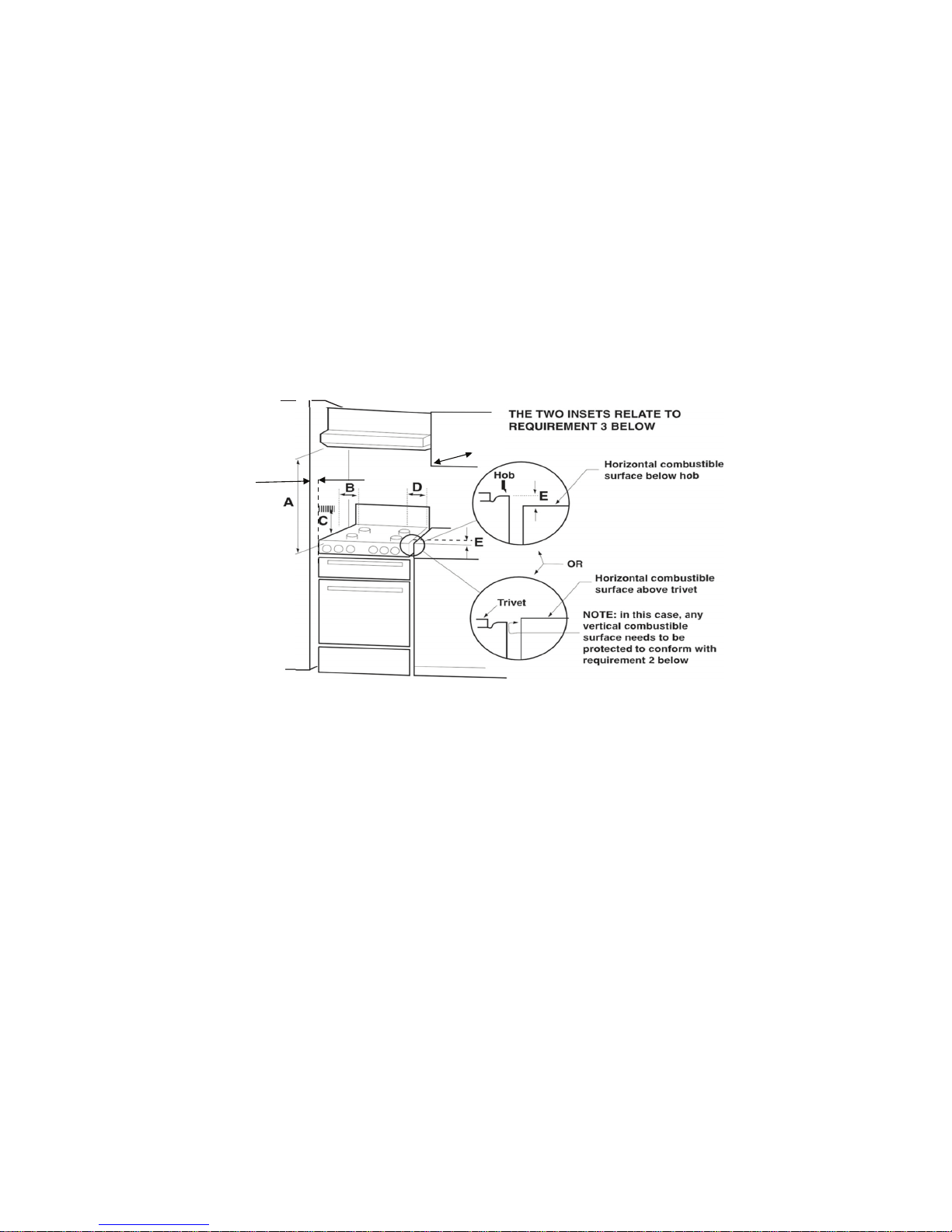
REQUIREMENTS
1. Overhead clearances – (Measurement A)
Range hoods and exhaust fans shall be installed in accordance with the manufacturer’s instructions.
However, in no case shall the clearance between the highest part of the hob of the cooking appliance
and a range hood or an overhead exaust fan be less than 700 mm. Any other downward facing
combustible surface less than 700 mm above the highest part of the hob shall be protected for the full
width and depth of the cooking surface area in accordance with clause 5.12.1.2. However, in no case
shall the clearance to any surface be less than 450mm. The maximum depth of wall cabinet above the
cooking shall be 400 mm.
2. Side clearances – (Measurements B & C)
Where B, measured from the periphery of the nearest burner to any vertical combustible surface, is
less than 200 mm, the surface shall be protected in accordance with Clause 5.12.1.2 to a height C of
not less than 200 mm above the level of the backguard for the full width of the cooking surface area.
Where the cooking appliance is fitted with a “splash back”, protection of the rear wall is not required.
The appliance can be installed between two walls. A single sidewall that exceeds the height of the
work surface is possible. This must be at a minimum distance of 70 mm from the edge of the cooker.
3. Additional requirements for Freestanding and Elevated Cooking Appliances (Measurements D & E)
Where D, the distance from the periphery of the nearest burner to a horizontal combustible surface is
less than 200 mm, then E shall be 10 mm or more, or the horizontal surface shall be above the trivet.
See inserts above.
Fig. 01
400mm max.
Clearance above and around domestic cookers
Page 9
Chapter 1 Ready, set up, go
9
IMPORTANT INFORMATION FOR INSTALLAING AND SERVICING THE APPLIANCE
The cooker can be installed separately, as a freestanding unit, or between kitchen units or between
a kitchen unit and the wall. This appliance is not connected to devices which exhaust combustion
products. Special attention must be focused on the prescriptions described below regarding room
aeration and ventilation. The dimensions of the appliance are listed below:
APPLIANCE SERVICING
IMPORTANT!
ALL SERVICING AND MAINTENANCE ARE TO BE COMPLETED BY THE MANUFACTURER’S
AUTHORISED PERSONNEL ONLY.
Before carrying any servicing operation disconnect the appliance from gas and electric supply and
extra appliance from final installation place in order to have access to the appliance for proper
servicing intervention.
GAS CONVERSION
WARNING!
Before carrying out this operation, disconnect the appliance from gas and electricity. Gas
conversion shall be conducted by a factory-trained professional. Call the customer service
hotline to identify a factory-trained professional near your home. The gas conversion
procedure for this range includes differents steps:
1. Pressure regulator
2. Surface burners
3. Main oven burner
4. Visual checks prior to closure of oven bottom panel
5. Adjustment of minimum setting
The conversion is not completed if all 5 steps have not been concluded properly.
Before performing the gas conversion, locate the package containing the replacement nozzle shipped
with every range.
IMPORTANT: Each nozzle has a number indicating its flow diameter printed on the body.
Consult the table on page 20 for matching nozzles to burners. Save the nozzles removed from the
range for future use.
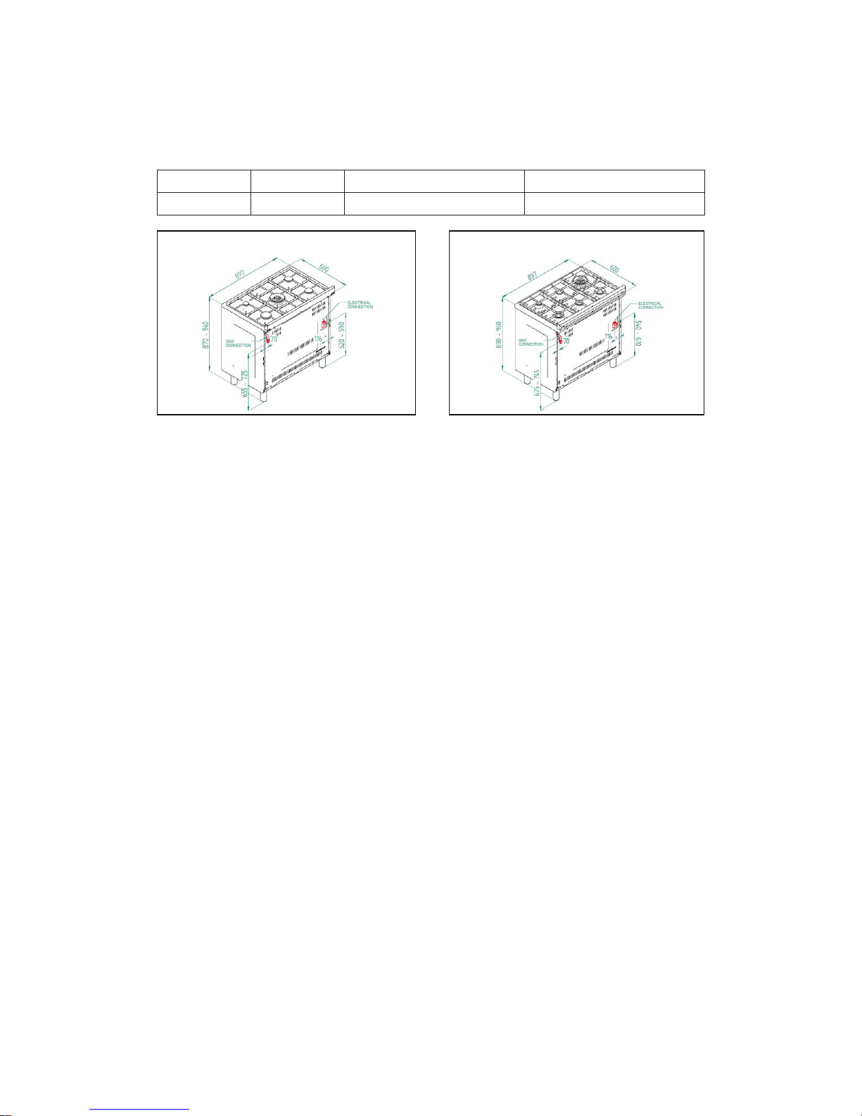
STEP 1: PRESSURE REGULATOR.
For NG or ULPG installation ref. to fig. 7 and chapter ‘Appliance gas connection’ at pag 7
LENGTH DEPTH HEIGHT with worktop stamped HEIGHT with worktop welded
897mm 600mm adjustable 870-940mm adjustable 890-960mm
Fig.2 Fig.3
Cooker with worktop stamped Cooker with worktop welded
Page 10
Chapter 1 Ready, set up, go
10
STEP 2: SURFACE BURNERS
For surface burners conversion ref to table 1 chapter ‘Adaption to various types of gas’ at page 8 and
chapter ‘Conversion to different types of gas’ at page 12
STEP 3: MAIN OVEN BURNER
For main oven burner conversion ref to table 1 chapter ‘Adaption to various types of gas’ at page 8 and
chapter ‘Conversion to different types of gas’ at page 12
STEP 4: VISUAL CHECKS
The following visual check must be performed to ensure that the conversion has been carried out
properly and without damage to other components of the range. Verify that the flame of the oven
burner be completely blue and with regular aspect as shown below.
CONNECTION OF THERMOCOUPLE TO THERMOSTAT
The thermocouple for oven burner is connected to the magnet. Tight gently the connection. The tip of
the spark plug or thermocouple must fully overlap at least the first gas emission hole of the burner.
After performing all these visual checks, reinstall the bottom panel of the oven compartment and
proceed to setting the minimum for each burner.
STEP 5: MINIMUM FLAME ADJUSTMENT
WARNING!
These adjustments should be made only for use of the appliance with Natural gas. For use with ULPG,
the choke screw must be fully turned in a clockwise direction.
Surface burners
Light one burner at a time and set the knob to the MINIMUM position (small flame). Remove the knob.
The range is equipped with a safety valve. Using a small-size slotted screwdriver, locate the choke
valve on the valve body and turn the choke screw to the right or left until the burner flame is adjusted
to desired minimum. Make sure that the flame does not go out when switching quickly from the
MAXIMUM to the MINIMUM position.
Oven burner
Set the oven temperature control knob to the MAXIMUM setting. Close the oven door and operate the
oven for at least 10 minutes. Set the knob to the MINIMUM setting. Remove the knob. With a slotted
screwdriver turn the choking screw (bypass screw at the left side of the thermostat bar) and, while
observing the flame at the same time through the bottom oven porthole, evaluate the consistency of
the flame so it remains on when switching quickly from MINIMUM to MAXIMUM setting.
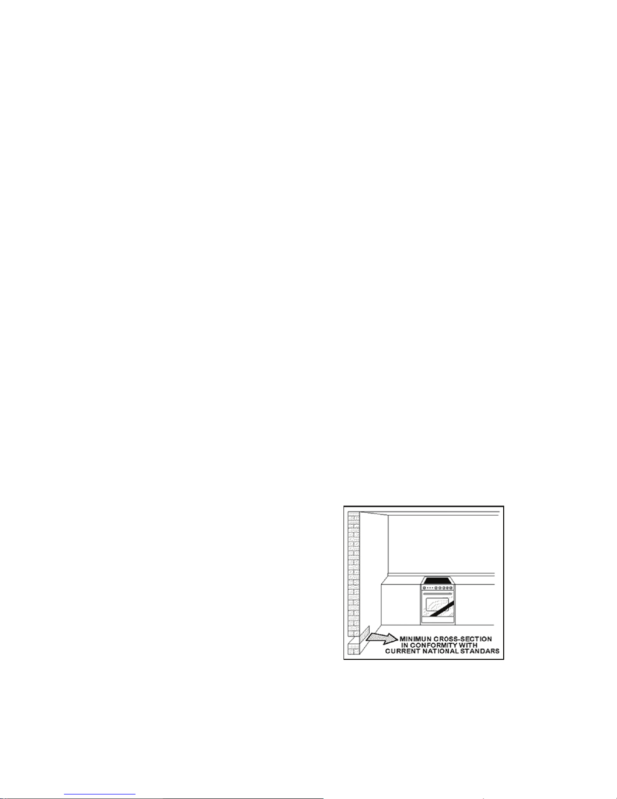
Room Ventilation
To ensure that the appliance operates correctly, the room
where it is installed must be continuously ventilated.
The room volume should not be less than 25m3 and the
quantity of air should be based on the regular combustion
of gas and on the ventilation of the room. Natural air will
flow through permanent openings in the walls of the room
to be ventilated. These openings will be connected with
the outside environment and should have a minimum
cross-section defined by current national standards
regarding room ventilation (Fig. 04).
These openings should be built so that they cannot be
clogged. Indirect ventilation is also permitted by taking air
from the rooms adjacent to the one to be ventilated.
Fig. 04
Page 11

Chapter 1 Ready, set up, go
11
Location and Aeration
Gas cooking appliances must always evacuate the combustion products by means of hoods connected
to chimneys, flues or directly outside (Fig. 05). If a hood cannot be installed It is possible to use a fan
installed on a window or directly facing outdoors, to be operated together with the appliance ( Fig. 06),
provided that there is strict compliance with the ventilation regulations.
APPLIANCE GAS CONNECTION
IMPORTANT: This appliance must be installed by an authorised person.
WARNING: DO NOT MODIFY THIS APPLIANCE
If the appliance cannot be adjusted to perform correctly, contact the service department.
This appliance utilises a threaded 1/2” gas male fitting. To connect the appliance to the gas
network with a flexible hose, a supplemental hose nipple fitting is needed which is supplied with
the appliance. (Fig. 07)
Gas Regulator
The gas connection is via 1/2” tapered thread. Connect the cooker to the gas supply and test for
leaks. NEVER use a naked flame to check for gas leaks.
Natural Gas: Gas regulator supplied with the appliance must be installed.
ULPG: Test point adaptor to be fitted and checked at time of installation.
Fig. 05
Fig. 06
Fig. 07
Gas inlet (mm) - Nat gas
From RH rear side: 70mm
Up from floor cooker with worktop stamped: 655-725mm
Up from floor cooker with worktop welded: 675-745mm
Gas inlet (mm) - ULPG
From RH rear side: 70mm
Up from floor cooker with worktop stamped: 570-640mm
Up from floor cooker with worktop welded: 590-660mm
Gas inlet positions with different leg heights - mm
Page 12

Chapter 1 Ready, set up, go
12
Using a flexible connection
This appliance is approved for connection with a flexible hose, which complies with the AS/NZS
1869 (Australian Approved), 10mm ID, class B or D, between 1-1.2m long. Connection shall be in
compliance with AS/NZS 5601 for a high level connection. The hose should not be subjected to
abrasion, kinking or permanent deformation and should be able to be inspected along its entire length.
Unions compatible with the hose fittings must be used and connections tested for gas leaks. The fixed
consumer piping outlet should be at approximately the same height as the cooker connection point,
pointing downwards and approximately 150mm to the side of the cooker. The hose should be clear of
the floor when the cooker is in the installed position.
When installing the hose restraint device, the appliance anchor point is the rear panel.
Using a Copper Pipe connection
The cooker must be connected to the gas supply with upstream connection of an isolation valve in
accordance with the respectively valid regulations. We recommend that the isolation valve be fitted
prior to the cooker to enable isolation of the cooker from the gas supply. The valve must be easily
accessible at all times. To find out the gas type factory settings, see label on the rear of the appliance.
Test the operation of the cooker before leaving
Note: These burners have no aeration adjustment.
Check correct operation of the ignitions system and operation of the regulator and operation of the
burners individually and in combination. Burner flames should be clear blue, with no yellow tipping.
If the burners show any abnormality check that the burners are correctly located. If satisfactory
performance cannot be obtained, contact service.
Important
Before leaving instruct the owner in the use of the
cooker it should be expressly noted that we cannot
accept any liability for direct or indirect damage
caused by wrong connection or improper installation.
When being repaired, the appliance must always be
disconnected from the mains supply; if required,
notify our customer service.
Burners Gas type Pressure (kPa) Injector (mm) Mj/hr By-pass size (mm)
Small Natural 1.00 0.90 4.00 0.30 regulated
Small ULPG 2.75 0.54 4.00 0.30
Medium Natural 1.00 1.18 7.00 0.36 regulated
Medium ULPG 2.75 0.70 7.00 0.36
Large Natural 1.00 1.55 11.50 0.52 regulated
Large ULPG 2.75 0.92 11.50 0.52
Wok Natural 1.00 1.80 14.50 0.65 regulated
Wok ULPG 2.75 1.02 14.50 0.65
Wok 2way Natural 1.00
Ex. 1.80
int. 0.50
17.50
Ex. 0.65 reg.
int. 0.34 reg.
Wok 2way ULPG 2.75
Ex. 1.02
int. 0.50
17.50
Ex. 0.65 reg.
int. 0.34 reg.
Oven Natural 1.00 1.95 16.50 0.62 regulated
Oven ULPG 2.75 1.10 16.50 0.62
TABLE N°1
Adaption to various types of gas
Burners Dimensions (mm)
Auxiliary ø50
Semi-rapid ø70
Rapid ø95
Wok ø125
Wok 2 ways ø135
TABLE N°2: GAS BURNER DIMENSION
Page 13

Chapter 1 Ready, set up, go
13
SUPPORT LEGS AND BACKGUARD INSTALLATION
The cookers are supplied with four transit supports (one for each corner). Four support legs are
supplied separately and are fitted on location to the four corners of the lower support frame. Each
support leg is pushed over the relevant transit support until flush with the support frame. Each leg
is adjusted by screwing the lowe r section in or out as required for fitting to a 900mm bench height.
For lower bench tops adjust the height of the legs to 180mm so the hob is located 10mm above the
horizontal combustible surface, ref. AS/NZS 5601.
Fig. 08
Legs should be installed with the appliance close to
its final destination, as the legs are not designed for
excessive force and will snap off if too much side force
is exerted on them (dragging along or angled too much).
When fitting, try to keep the appliance as close to a
horizontal position as possible. Use of a pallet jack is
recommended. If the legs are not used and the cooker is
mounted onto a plinth, four transit supports allow
for clearance.
With the legs fitted, the backguard supplied with the
appliance can be fitted.
Follow the instructions shown in Fig. 09.
ATTENTION: TAKE CARE DO NOT OBSTRUCT THE
OUTLET OPENINGS ON THE BACKGUARD; THEY MUST
BE UNOBSTRUCTED FOR PROPER OPERATION
Fig 09
Page 14

Chapter 1 Ready, set up, go
14
Left Side o f oven,
chain not attached
ANTI-TILT DEVICE AND STRAIN RELIEF FLEXIBLE HOSE DEVICE
ANTI-TILTING CHAIN/HOSE RESTRAINING CHAIN
A chain must be fitted by the installer within 50mm of the hose connection point to prevent strain on
the hose when the cooker is pulled forward. The chain should restrict the appliance movement to no
more than 80% of the hose length. After the chain is installed, check that there is no strain on the hose
or gas connections when the cooker is pulled as far forward as the chain allows.
The cooker is also supplied with two chains which are connected to the rear left and right of the
appliance. The chains should be connected to the wall directly behind the chains as low as possible
to prevent the appliance from tilting forward. If the appliance is installed between two cupboards,
drill a hole on each side of the cupboards, pass the chains through the holes and anchor the chains
within each cupboard. Ensure the chain connections are strong enough to support the weight of the
appliance and taught to prevent it from tilting forward.
WARNING! In order to prevent accidental tipping of the appliance, for example a child climbing onto
the open oven door, the stabilising means must be installed. Ensure the chains are correctly anchored
to prevent the appliance from tilting forward and to prevent strain on the hose when the cooker is
pulled forward.
MAKE SURE THE ANTI-TILTING CHAINS ARE TAUGHT WHEN ANCHORED AND ANTI TILT
RESTRAINT IS INSTALLED TO PREVENT THE APPLIANCE TILTING
Please refer to the next two pages for examples of incorrect and correct chain installation.
Accidental tipping
Chains are provided as a preventative
measure against accidental tipping. These
chains must be fitted as part of the installers
compliance. Failure for your installer to
fit chains in accordance with the relevant
installation code will make the installation
of your upright cooker noncompliant and
class an
illegal installation.
Incorrect installation
The photographs on this page are of one
single kind of incorrect installation (although
there are many) which does not have the
chains sufficiently secured, figure 1. Shows
an example of how far forward an oven
can tip when not secured properly. Note:
Correct installation is part of the installer
compliance.
Hole in c abinet t oo
large, a llowing the
upright oven to tilt
forward.
Unfortunately the example on this page is the way
many installers are installing uprights. This may
believe that they are using the correct method by
putting the chain through a hole into the adjacent
cabinet and screwing the chain to the back wall but
it will not work if not properly.
Putting the chain into the adjacent cabinet is the
preferred method, provided there is no slackness in
the chain.
Some installations only have a single chain affixed.
Both chains must be fixed as part of the installers
compliance. Failure to fix both chains will make the
installation non compliant
Loose Chain
Page 15

Chapter 1 Ready, set up, go
15
Left Side
Right Side
In order to prevent the oven from tipping
forward as shown on the previous page,
we need to make sure both chains
provided with the oven are used.
On the left side of the oven a 16mm
drill bit was used to drill through the
cabinetry into the adjacent cabinet,
as you can see the hole has not been
drilled hard up against the wall because
there is a 16 mm board at the rear of
the cabinet. The heigt of the hole from
the floor is level with where the chain
attaches to the oven.
The right side has been drilled much the
same, a new hole has been drilled below
the gas and power supply hole
Once the holes have been drilled the chains can be fed trough and the
upright can be fitted into position.
The chains then need to be pulled as tight as possible from inside
the cabinet using a self drilling wood screw. It is better to have the
screw fixed closer to the hole for better support. The left and right
side examples shown have two extra screws attached to the chain
which makes the installation neater by keeping the chain off the shelf
away from the gas and electricity supply, they will also provide added
support.
At this point the oven will be secured in location and will not move
forward at all, it is recommended that all upright oven chains be fitted in
this way.
Installation forms part of the installer compliance and that in line with
AGA regulations chains are designed to be installed to prevent cooker
from tilting. They are not designed to replace parental supervision when
the cooker is in use.
Page 16

Chapter 1 Ready, set up, go
16
WARNING: In order to prevent accidental tipping of the appliance, for example a child climbing onto
the open oven door, the stabilising means must be installed. Ensure the chains are correctly anchored
to prevent the appliance from tilting forward and to prevent strain on the hose when the cooker is
pulled forward.
MAKE SURE THE ANTI-TILTING CHAINS ARE TAUGHT WHEN ANCHORED TO PREVENT THE
APPLIANCE TILTING.
CONVERSION TO DIFFERENT TYPES OF GAS
Before performing any maintenance operation, disconnect the appliance from the gas supply and
electricity network.
REPLACING THE NOZZLES TO OPERATE WITH ANOTHER TYPE OF GAS
When converting to ULPG remove the NG gas regulator (if fitted) and fit ULPG test point adaptor.
If converting to Natural Gas, fit gas regulator
Follow the instructions below to change the burner nozzles on the work surface:
1) Pull out the plug from the electric outlet to avoid any type of electric contact.
2) Remove the grids from the work surface (Fig. 11).
3) Remove the burners (Fig. 11).
4) Unscrew the nozzles using a 7 mm spanner, and replace them (Fig.12) with those needed for the
new type of gas according to what is indicated in the Energy Consumption Table.
Fig 010
Fig. 11 (representation only)
Fig.12
Page 17

Chapter 1 Ready, set up, go
17
5) Burner “MINIMUM” adjustment:
Work surface burner adjustment: follow the instructions below to adjust the work surface
burner minimum:
• Light the burner and set the knob to the MINIMUM position (small flame).
• Remove the knob of the valve that is press fit on the rod of that valve.
• For all burners except for the wok burner, insert a small slotted screwdriver into the hole on the
valve rod (Fig. 13) and turn the choke screw to the right or left until the burner flame is adjusted
to minimum.
• The wok burner has 2 adjustment screws on either side of the body of the valve (Fig. 14). Screw A
is for the outer ring and screw B is for the inner ring. Turn the choke screw to the right or left until
the burner flame is adjusted to minimum.
• Ensure sure that the flame does not go out when s witching quickly from the MAXIMUM to the
MINIMUM position.
Fig. 13 Fig.14 Fig.15
Page 18

Chapter 1 Ready, set up, go
18
APPLIANCE ELECTRICAL CONNECTION
The electric connection must comply with the current legal standards and regulations. Before making
the connection, check that:
• The system electrical rating and the current outlet are adequate for the maximum power output of
the appliance (see the label applied to the bottom of the casing).
• The outlet or the system is equipped with an efficient ground connection in accordance with
the current legal standards and regulations. The manufacturer will not be responsible for the
noncompliance with these instructions.
• The power cord is supplied with a 15A plug, suitable for the load indicated on the label and a
standard 15A GPO.
• The power cord must be positioned so that a temperature of 75°C will not be reached
at any point.
• Do not use reductions, adapters or splitters since they might cause false contacts and lead to
dangerous overheating.
When the connection is made directly to the electric network:
• Use a device that ensures disconnection from the mains in which the contacts are opened to
a distance that permits complete disconnection according to the conditions for over-voltage
category III.
• The disconnection must be incorporated in the fixed wiring in accordance with the wiring rules.
• The ground wire must not be interrupted by the circuit-breaker.
• As an alternative, the electric connection can also be protected by a high-sensitivity residual
current circuit- breaker but this may be subject to nuisance tripping due to residual humidity in
heating elements.
• It is highly recommended to attach the special green-yellow ground wire to an efficient
ground system.
WARNING: If the power cord is replaced, the ground wire (yellow-green) connected to the
terminal, should be longer than the other wires by about 2 cm.
WARNING: if the supply cord is damaged, it must be replaced by the manufacturer or its
service agent or similarly qualified person in order to avoid a hazard.
Fig. 16
Letter L (phase) =brown w i r e ;
Letter N (neutral) = blue w i r e ;
Ground symbol = green - yello w
wi r e ;
Work surface operation Oven operation
Cross section
230V ~
Only gas burner
Multifunction electric oven 3 x 1.5mm
2
Gas oven/Electric grill 3 x 1mm
2
TABLE N°3: TYPES OF POWER CORDS
The appliance conforms to the regulation AS4551 regarding gas appliance for domestic use and
AS/NZS60335.26 regarding safety and CSPR 14 regarding electromagnetic compatibility.
Page 19

Chapter 1 Ready, set up, go
19
INSTALLATION CHECKLIST
1. Is the range mounted on its legs?
2. Is the backguard securely connected?
3. Has the anti-tip device been properly installed?
4. Does the clearance from the side cabinets comply with the manufacturers directions?
5. Is the electricity properly grounded?
6. Is the gas service line connected following the directions of the manufacturer?
7. Have all the proper valves, stoppers and gasket been installed between the range and the service
line?
8. Has the gas connection been checked for leaks?
9. Has the range been set for the type of gas available in the household?
10. Is the ignition of all oven burners functioning properly?
11. Does the flame appear sharp blue, with no yellow tipping, sooting or flame lifting?
12. Has the minimum setting for all burners been adjusted?
13. Is the oven ignition working properly?
14. Does the oven light work properly?
Before Leaving - Check all connections for gas leaks with soap and water. DO NOT use a naked flame
for detecting leaks. Ignite all burners both individually and concurrently to ensure correct operation
of gas valves, burners and ignition. Turn gas taps to low flame position and observe stability of the
flame for each burner individually and concurrently. When satisfied with the hotplate, please instruct
the user on the correct method of operation. In case the appliance fails to operate correctly after all
checks have been carried out, refer to the authorised service provider in your area.
Page 20

Chapter 1 Ready, set up, go
20
SETTING THE TIME
After connecting the unit to power, the symbols 0:00 will be shown on the display.
1. Press the ‘mem.’ button until the hour figure flashes.
2. Press the ‘plus and minus’ buttons to adjust the hour figure.
3. Press the ‘mem.’ button so the minute figures flash.
4. Press the ‘plus and minus’ to adjust the minute figure.
5. Press the ‘mem.’ button to confirm the new time settings.
ENVIRONMENTAL INFORMATION
This Franke appliance is particularly energy efficient, however to make the most out of it, and to save
even more energy make sure you adhere to the following steps:
1. Open the appliance door as infrequently as possible during operation.
2. It is best to bake several items on after the other, as the cooking compartment is still warm.
3. Only preheat the appliance if necessary for the recipe
4. For longer cooking times, you can switch the appliance off 10 minutes prior to the end cooking
time, and use the residual heat.
DISPOSAL
Dispose of all packaging in an environmentally friendly manner. Franke practises environmentally
conscious behaviour, and this appliance is labelled in accordance with the used electrical and
electronic appliances waste guidelines.
If you have any questions on disposals, please call the Franke customer service
team on 03 9700 9100.
Select Oven
Function
Select Oven
Temp.
Gas Cooktop
Control
Memory
PlusMinus
Page 21

21Chapter 2 Life with your Franke upright cooker
life with your franke
upright cooker
CHAPTER 2
We designed this upright cooker with one thing in mind.
How do we create a wonderfully simple user experience
for you, our customer?
Page 22

22Chapter 2 Life with your Franke upright cooker
UPRIGHT COOKER FUNCTIONS
Convection
A heating element plus fan force. This results in an even distribution of heat.
Default temperature 180°C.
Quick Start/Defrost
This function runs the rear fans and all elements. The heat generated is too
hot to cook in, but is perfect for preheating the oven (run at the required
temperature until the thermostat light turns off and on a couple of time, then
adjusts to the required function setting. To use as a defrost function, leave the
thermostat on 0. This allows air to flow over frozen food speeding up
defrost times.
Bottom Heat
A concealed element in the bottom of the oven provides a concentrated heat to
the base of food (ideal for pizzas). Default temperature 60°C.
Conventional Cooking
A top and bottom heating element work together to provide conventional
cooking. Default temperature 220°C.
Double Grilling with Fan
The inside radiant heating element, and top element are working with the fan.
Default temperature 210°C.
Radiant Grilling
The inner grill element maintains the temperature.
Default temperature 210°C.
Double Grilling
The inside heating element and top element working together.
Default temperature 210°C
Convention with Fan
Combination of both the heating elements and the fan. This is also the most
energy efficient setting. Lightly browned on the outside, moist on the inside
(ideal for roasting).
Page 23

23Chapter 2 Life with your Franke upright cooker
OPERATING YOUR UPRIGHT COOKER
To select a cooking function and choose your desired temperature:
1. Rotate the ‘left knob’ to choose the cooking function.
The symbol chosen will be shown.
2. Rotate the ‘right knob’ to adjust the temperature to your desired pre-set.
3. The oven will automatically begin cooking function.
4. The orange LED indicator shows if the oven has reached your desired temperature.
5. Rotate both control knobs to the off position to switch the oven off.
USING THE TOUCH CLOCK
Mains frequency detection
At power on mains frequency is determined. When the timer is connected to 60Hz, the Celsius symbol
is flashing during start-up.
Power On
At power on, the relay contact is opened. The display and AUTO symbol flashes and time of day starts
from 0:00. Power on state with flashing daytime remains until time of day is set.
Setting Time of Day
Press PLUS and MINUS button simultaneously. At Power On, also MODE button is possible.
Time of day can be set with PLUS or MINUS, while the colon between hours and minutes is flashing.
Quick setting mode starts when PLUS or MINUS is held for more than 1 second. If daytime setting
mode is selected while an automatic program is active, the automatic program Fig.27 is cancelled.
The Buzzer
The buzzer interval alarm signal sounds if minute minder has reached the end time. The signal can be
switched off by pressing any key or by passing the signal duration limit.
Changing the Buzzer frequency
First press Plus and Minus simultaneously (menu far editing the time) and then Mode for selecting the
menu far changing the buzzer frequency. While the text is visible the buzzer signal frequency can be
changed by touching Minus repetitively.
Note: If the touch pad is inactive, a visual alarm will only be reset when a valid key combination is
pressed far more than 2 seconds.
Clearing Programs and Manual function
The duration of the minute minder can be cleared by
a) “Clear Function”: First select minute minder program, then press PLUS and MINUS
button simultaneously. after this clear the display returns from adjustment mode to time
of day immediately.
b) Back counting of duration to zero. The timer remains in adjustment mode.
Minute Minder
While minute minder mode is selected, the Bell symbol flashes and the display reads the remaining
time in hours and minutes, only if the last minute is counting down the remaining seconds are
displayed. An active minute minder program is indicated by the statically illuminated Bell symbol. If
alarm time has finished, an acoustic interval signal sounds and the Bell symbol flashes. The minute
minder program runs independently of other programs.
Key Lock
After power on reset or when no key is pressed for 7 seconds, the key look function is activated.
Pressing a valid key or key combination for 2 seconds or more will deactivate the key lock.
Page 24

24
getting the most out of
your franke upright cooker
CHAPTER 3
Getting the most out of your Franke upright cooker.
Your Franke upright cooker turns work into play, and
inspires creativity every single day.
Chapter 3 Getting the most out of your Franke upright cooker
Page 25

25Chapter 3 Getting the most out of your Franke upright cooker
CLEANING AND CARE
We want your Franke Appliance to be looking this good for a long time to come. To ensure that the
various surfaces are not damaged through cleaning, please observe the following:
Glass: Glass cleaner and with a microfiber cloth.
Plastic: Hot soapy water with a soft cloth.
Control panel: Clean with a dish cloth and then dry with a soft cloth.
Interior enamelled surfaces: A mix of hot soapy water, vinegar and lemon juice. Wash with a dish
cloth, and then allow the cooking compartment to dry.
Accessories: Hot soapy water and if there are stubborn food deposits, use a stainless steel
scouring pad.
Rails: Hot soapy water and a dish cloth.
Stainless steel handle: Hot soapy water and a mild stainless steel cleaning product with a soft cloth.
INTERIOR LIGHTING
If the interior lighting bulb or cover is defective for any reason or the light no longer operates, please
call our service team for support.
TIPS FOR USING BURNERS CORRECTLY:
Use suitably sized pots for each burner (see tab. 4 and Fig. 20).
• When the liquid is boiling turn the knob to the MINIMUM position (small flame Fig. 18).
• Use pots with a cover when available.
• Large utensils exceeding the recommended maximum size can cause excessive heat to reflect
back onto the appliance, potentially damaging the appliance and causing a temperature hazard.
Fig. 20
BURNER PAN DIAMETER recommended (cm)
Auxiliary 12-14
Semi-rapid 14-26
Rapid 18-26
Wok 22-26
Wok 2 ways 22-50
Page 26

26Chapter 4 Problem, meet solution
problem, meet solution
CHAPTER 4
We don’t expect your experience with your new Franke
upright cooker to be anything but wonderful, but here’s
some trouble shooting remedies just in case.
Page 27

27Chapter 4 Problem, meet solution
TROUBLE SHOOTING
You shouldn’t have any issues with your Franke Appliance, however there are some problems which
can easily be fixed by trouble shooting the table below. If you can’t find your problem, or the remedy
has not fixed the issue, then give our friendly customer service team a call on 03 9700 9100.
Problem Solution
Oven or hob not working
Check the electricity is turned on. Check your fuses. If
the fuse continues to blow, call PR Kitchen & Washroom
Systems Pty Ltd service. Check the circuit breaker. Ensure
correct knob is positioned correctly. Dry or clean ignition
electrodes. Make sure flame ports and ignition areas are
clean and dry. Check gas main supply is on. Ensure
cap/crown correctly fitted. Replace or tighten light globes.
Heating up problems
Oven not pre-heated: Pre-heat oven for 10 minutes. Check
oven door is closed properly. Remove foil or trays from
bottom of oven. Change oven temperature. Pre-heat oven
before putting the food in to be cooked.
Unit smoking/odours
Turn the oven on high to remove protective oils. Persistent
gas smell: do not operate the cooker call PR Kitchen &
Washroom Systems Pty Ltd service.
Condensation
Note: some condensation
is normal and is to be
expected during cooking.
Reduce the amount of water used for cooking.
Leave the door open after cooking if food remains in
cooker for warming.
Oven shelves are tight
Remove oven shelf and re-insert.
Cooling fan runs after ovens
turns off
This is normal and not a fault.
Abnormal Operation
Any of the following are considered to be abnormal operation and may require servicing: Yellow tipping
of the hob burner flame. Sooting up of cooking utensils. Burners not igniting properly. Burners failing
to remain alight. Burners extinguished by cupboard doors. Gas valves, which are difficult to turn. In
case the appliance fails to operate correctly, contact the authorised service provider in your area”.
Page 28

28Chapter 5 Last but not least
last but not least
CHAPTER 5
This section contains the warnings, precautions and
legal notices to make sure everything runs smoothly.
Page 29

29Chapter 5 Last but not least
UPRIGHT COOKER DOOR PRECAUTIONS
Never apply pressure on the upright cooker door when it is closed or open. Never use the upright
cooker door as a seator bench or apply any pressure to it while it is open. Do not place cookware or
accessories on the
upright cooker door.
Glass that has become scratched poses a risk of cracking and ultimately shattering which is a serious
risk to injury. Ensure that glass scraper or any sharp objects are kept away from the upright cooker at
all times.
The hinges on the upright cooker door pose a threat for you hands to be trapped. Keep hands clear of
the opening with operating the upright cooker door.
ELECTRIC SHOCK HAZARD
Never carry out an repairs yourself, always get an authorized technician to do any repairs or
maintenance on your upright cooker. If any electrical components become damaged or there is
exposed wiring, there is a risk of electrical shock.
Ensure whenever the upright cooker is in operation and you come into contact with it, that appropriate
footwear is worn.
APPLIANCE USE AND MAINTENANCE
ATTENTION: Important Warnings.
ATTENTION: ATTENTION: TAKE CARE DO NOT OBSTRUCT THE
OUTLET OPENINGS ON THE BACKGUARD; THEY MUST BE
UNOBSTRUCTED FOR PROPER OPERATION
• For cookers resting on base
ATTENTION: if the cooker rest on a base, take the
measures necessary to prevent the cooker from sliding
along the support base.
• For cookers with electric ovens
ATTENTION: The unit becomes hot during use. Do not touch the heating elements inside the oven.
ATTENTION: The accessible parts can become hot during use. Keep children away from the
appliance.
• For glass doors
ATTENTION: Do not use harsh abrasive cleaning products or metal spatulas with sharp edges to
clean the oven door’s glass since this could scratch the surface and the glass could break.
• For gas cooktops
ATTENTION: Clean burner tops and trivets at least once a week, or after any spillage. Gas inlet
pipes should be checked periodically for leakages (see section on leak testing), at intervals not
exceeding 12 months. Lubrication of valves should only be performed by an authorised person,
and is required if the gas control knobs become stiff and difficult to turn.
Do not use steam cleaner to clean the appliance.
WARNING: DO NOT MODIFY THIS APPLIANCE
Please maintain your appliance regularly.
Page 30

30
REPLACING PARTS
Before performing any maintenance operations, disconnect the appliance from the g a s supply and
electricity network. To replace parts such as knobs and burners, just remove them from the seats
without dis assembling any part of the cooker. To replace parts such as nozzle supports, valves and
electric components follow the procedure described in the burner adjustment paragraph. To replace
the valve or the gas thermostat, it is also necessary to disassemble the two rear gas train brackets,
loosening the 4 screws (2 per bracket) that attach it to the rest of the cooker and, unscrew the nuts
that attach the front burner valves to the control support, after removing all the knobs. To replace the
gas or electric thermostat, also disassemble the rear cooker guard, loosening the relative screws, to
be able to pull down and reposition the thermostat bulb. To replace the oven bulb, just unscrew the
protection cap that projects out inside the oven (Fig.17).
WARNING: Ensure that the appliance is switched off before replacing the lamp to avoid the
possibility of electric shock.
WARNING: The power cord supplied with the appliance is connected to the appliance with an X type
connection (in compliance with standards AS/NZS 60335-1, AS/NZS 60335-2-6 and subsequent
amendments) for which it can be installed without the use of special tools, with the same type of cord
as the one installed.
If the power cord becomes worn or damaged, replace it based on the information reported in table 2.
To replace the power cable, lift the terminal board’s cover and replace the cable.
Chapter 5 Last but not least
Fig.17
Page 31

31Chapter 5 Last but not least
HAZARDS
The following is a comprehensive list of all hazards and risks this product possesses.
Risk of fire:
• Any combustible items left in or near the upright cooker during operation
• Be aware of baking paper coming into contact of the heating element.
Risk of burns:
• The appliance becomes very hot. Never touch any surfaces or compartments which has been
exposed to the heating elements.
• Accessories also become very hot. Use appropriate gloves and upright cookerware.
• Alcoholic vapours may catch fire. Never use a high quantity of alcohol in a cooking recipe.
Risk of scalding:
• Any liquid in the cooking compartment may become hot and potentially dangerous if not
handled carefully.
Risk of magnetism:
• Magnets are used during the creation and operation of the control panel.
Keep away all pace makers.
Risk of electric shock:
• The insulation and coating of upright cooker accessories may cause electric shock if they come
into contact with electrical components.
Risk of death or serious injury to human health:
• The cables and wiring harnesses at the rear of the upright cooker must not be tampered with or
come into contact with the hot appliance.
• If the appliance is not operating correctly, do not continue to operate it.
Discuss your problem with our customer service team.
Page 32

32
GLOSSARY
Abrasive - a course and harsh substance capable of polishing or cleaning a surface by rubbing or
grinding.
Buzzer - a device that makes a loud noise and is used to signal something.
Cabinetry - a collection of cupboards with drawers or shelves.
Circuit breaker - and automatic device for stopping the flow of current in an electrical circuit for
safety reasons.
Control display - an electrical component which depicts various function on a screen, usually LED.
Convection - a fan with a heating element which provides heat. This improves the
heat transfer.
Conventional - the heat source is stationary, usually radiating from the bottom or top.
Enamelled - a coat of paint which is extremely heat resistant. It is applied by fusion to the metal.
Food residue - a small amount of food which remains after cooking.
Heating element - converts electricity into heat through resistive current.
Insulation - protecting or shielding an object from excessive heat or moisture.
Licensed professional - a person who has had the proper training and prerequisite to complete a
certain job.
Manufacturer - the person or organisation which is the original producer of a product.
Metal scraper - a single edged tool used to scrape a surface clean.
Packaging - the materials used to wrap or protect goods.
Radiant grilling - dry heat applied from above or below from a heating element.
Rotary knob - a wheel which control certain function and can spin left or right.
Scalding - very hot burning and blistering
Timer - used to indicate how long a process has left remaining.
Trouble shooting - finding the causes of common problems.
User experience - the overall experience of a person using a product, in terms of how easy or
pleasing it is to use.
Warranty - a written guarantee promising to repair or replace a product under certain circumstances
within a certain time.
Glossary
Page 33

33
PR Kitchen & Washroom Systems
83 Bangholme Road
Dandenong South
VIC 3175
Australia
Phone +61 3 9700 9100
Fax +61 3 9700 9191
info@prks.com.au
www.franke.com.au
PR Kitchen & Washroom Systems NZ Ltd
P.O Box 53171, Auckland Airport
Auckland 2150
New Zealand
Phone 09 964 0400
Fax 09 964 0401
info@prks.co.nz
www.franke.co.nz
 Loading...