

Page 1
Instructions for use and installation
Istruzioni per l’uso e l’installazione
Mode d’emploi et installation
Bedienungsanleitung und Einrichtung
Kullan
ım ve montaj talimatları
GB
IT
FR
DE
TR
Cooker Hood
Cappa
Hotte de Cuisine
Dunstabzugshaube
Davlumbaz
FDMO 607 I
Page 2

EN
Instructions Manual
INDEX
RECOMMENDATIONS AND SUGGESTIONS......................................................................................................................7
CHARACTERISTICS..............................................................................................................................................................8
INSTALLATION ....................................................................................................................................................................10
USE.......................................................................................................................................................................................14
MAINTENANCE....................................................................................................................................................................15
2
2
Page 3
EN
RECOMMENDATIONS AND SUGGESTIONS
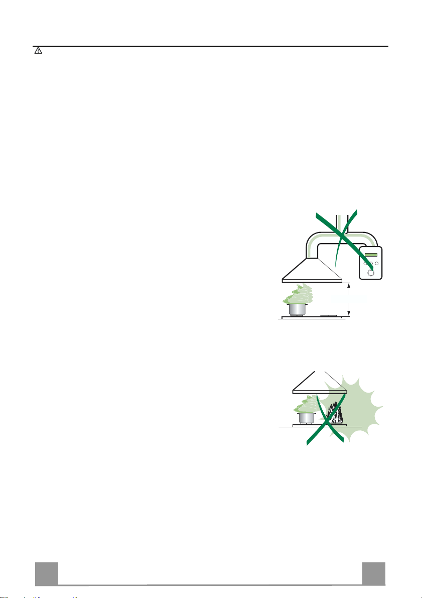
650 mm min.
The Instructions for Use apply to several versions of this appliance. Accord-
ingly, you may find descriptions of individual features that do not apply to your
specific appliance.
INSTALLATION
• The manufacturer will not be held liable for an y damages resulting fro m incorrect or impro per installat ion.
• The minimum safety distance between the cooker top and the extractor hood
is 650 mm.
• Check that the mains voltage corresponds to that indicated on the rating plate
fixed to the inside of the hood.
• For Class I appliances, check that the domestic power supply guarantees adequate earthing.
Connect the extractor to the exhaust flue through a pipe of minimum diameter
120 mm. The route of the flue must be as short as possible.
• Do not connect the extractor hood to exhaust ducts carrying combustion fumes
(boilers, fi replaces, etc.).
• If the extractor is used in conjunction with non-electrical appliances (e.g. gas
burning appliances), a sufficient degree of aeration must be guaranteed in the
room in order to prevent the backflow of exhaust gas. The kitchen must have
an opening communicating directly with the open air in order to guarantee the
entry of clea n air.
USE
• The extractor hood has been designed exclusively for domestic use to eliminate kitchen smells.
• Never use the hood f or purposes other than for which it has ben designed.
• Never leave high naked flames under the hood when it is in operation.
• Adjust the flame intensity to direct it onto the bottom of the pan only, making
sure that it does not engulf the sides.
• Deep fat fryers must be continuously monitored during use: overheated oil can
burst into flames.
• Do not flambè under the range hood; risk of fir e
• This appliance is not intended for use by persons (including children) with reduced physical, sensory or mental capabilities, or lack of experience and
knowledge, unless they have been given supervision or instruction concerning
use of the appliance by a person responsible for their safety.
• Children should be supervised to ensure that they do not play with the appliance.
MAINTENANCE
• Switch off or unplug the appliance from the mains supply before carrying out
any maintenance work.
• Clean and/or replace the Filters after the specified time p eriod.
• Clean the hood using a damp cloth and a neutral liquid deter gent.
7
7
Page 4
EN
CHARACTERISTICS
24
15
29
9
2
12c
1
25
14
11
12h
21
23
22
7.1
7.1b
7.1a
12g
12f
26
12w
13
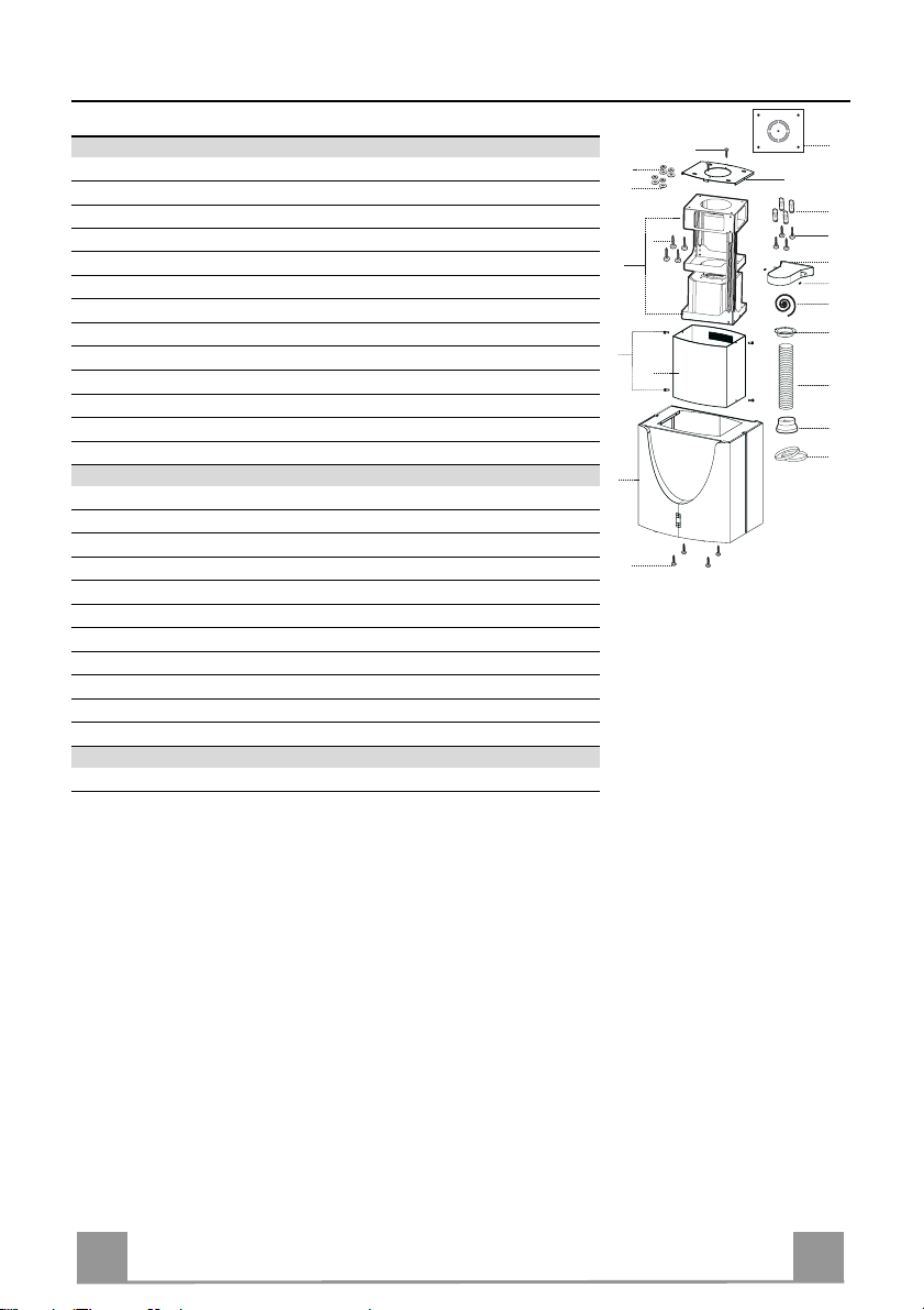
Components
Ref. Q.ty Product Components
1 1 Hood Body, complete with: C ontrols, Light, Blower, Filters
2 1 Upper Chimney
7.1 1 Telescopic f rame complete with extrac tor, consist ing of:
7.1a 1 Upper frame
7.1b 1 Lower frame
9 1 Reducer Flange ø 150-120 mm
13 1 Gasket
14 1 Hood Body Air Out let Extension Piece
15 1 Air Outlet Connection
25 2 Pipe clamps
26 1 Fixing Part of the upper Chimney
29 1 Air outlet connection tube
Ref. Q.ty Installation Components
11 4 Wall Plugs ø 10
12c 4 Screws 2,9 x 9, 5
12f 4 Screws M6 x 15
12g 4 Screws M6 x 80
12h 4 Screws 5,2 x 70
12w 2 Screws M3 x 8
21 1 Drilling template
22 4 6.4 mm int. dia washers
23 4 M6 nuts
24 2 Fixing knobs f or the air outlet connection piece
Q.ty Documentation
1 Instruction Manual
8
8
Page 5
EN
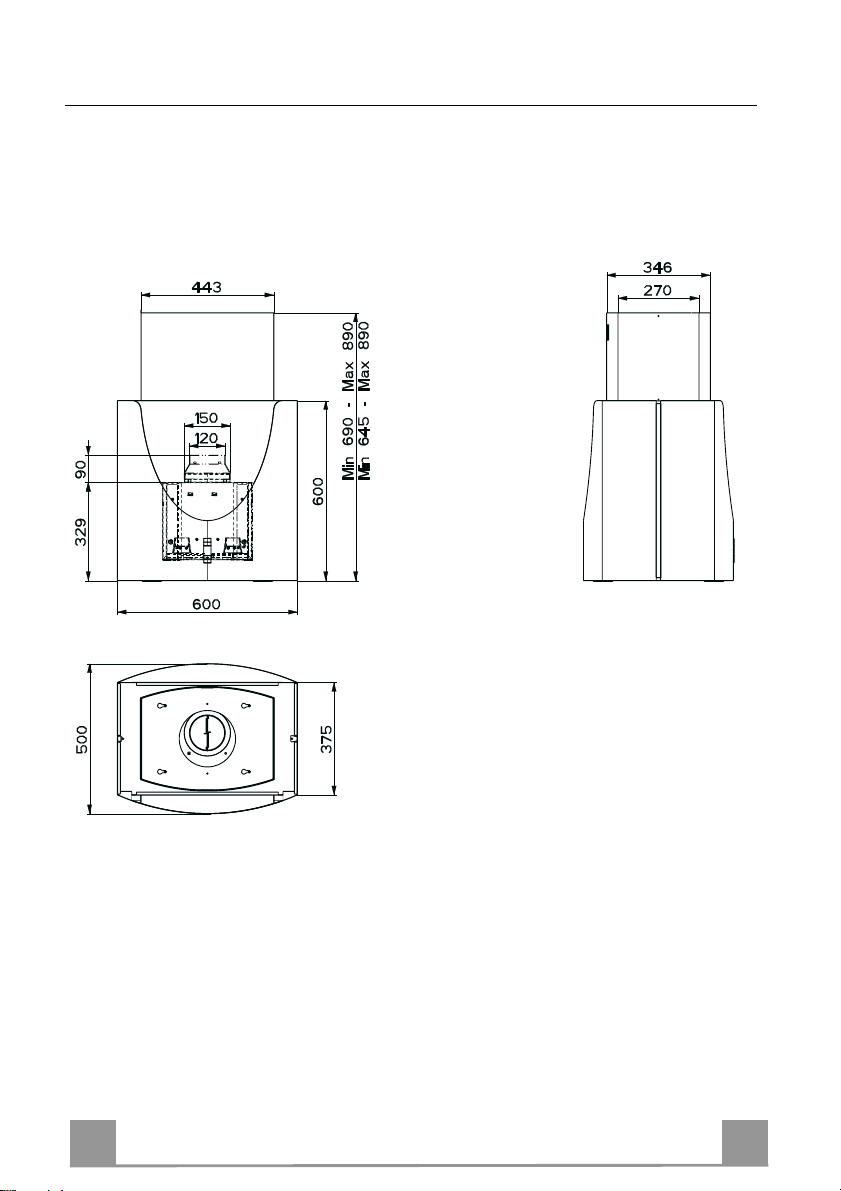
Dimensions
**
*
* Dimensions of the hood in ducting version.
** Dimensions of the hood in recycling version.
9
9
Page 6
EN 110
INSTALLATION
Drilling the Ceiling/shelf and fixing the frame
DRILLING THE CEILING/SHELF
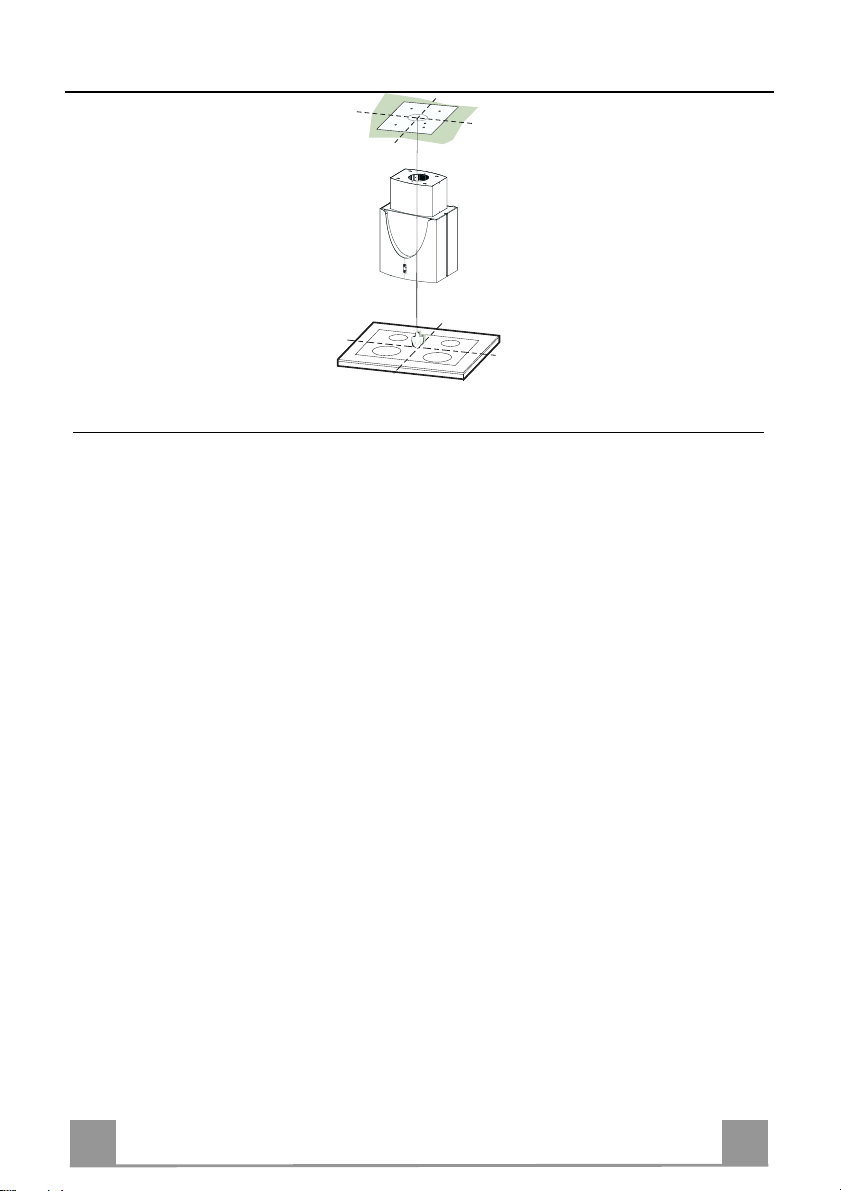
• Use a plumb line to mark the centre of the hob on the ceiling/support shelf.
• Place the drilling template 21 provided on the ceiling/support shelf, making sure that the
template is in the correct position by lining up the axes of the template with those of the hob.
• Mark the centres of the holes in the template.
• Drill the holes at the points marked:
• For concrete ceilings, drill for plugs appropriate to the screw size.
• For hollow brick ceilings with wall thickness of 20 mm: drill ø 10 mm(immediately insert
the Dowels 11 supplied).
• For wooden beam ceilings, drill according to the wood screws used.
• For wooden shelf, drill ø 7 mm.
• For the power supply cable feed, drill ø 10 mm.
• For the air outlet (Ducted Versio n), drill according to t he diameter of the external air exhaust duct connection.
• Insert two screws of the following type, crossing them and leaving 4-5 mm from the ceiling:
• For concrete ceilings, use the appropriate plugs for the screw size (not provided).
• for Cavity ceiling with inner space, with wall thickness of approx. 20 mm, Screws 12h,
supplied.
• For wooden beam ceilings, use 4 wood screws (not provided).
• For wooden shelf, use 4 screws 12g with washers 22 and nuts 23, provided.
Page 7
EN 111
FIXING THE FRAME
quired, then
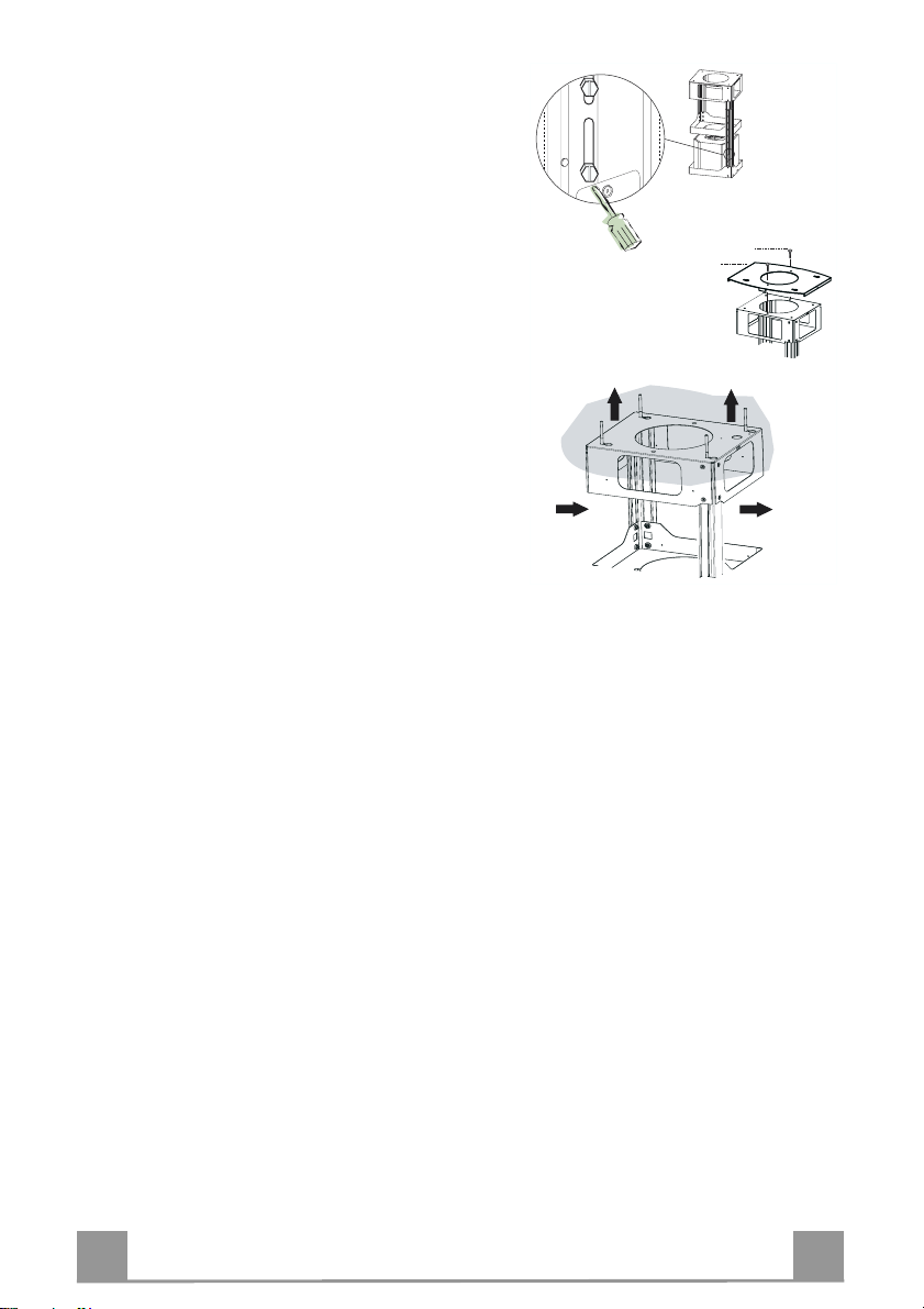
If you wish to adjust the height of the frame, pro ceed
as follows:
• Unfasten the metric screws joining the two columns,
located at the sides of the frame.
• Adjust the frame to the height re
replace all the screws removed as above.
• Fix the Fixing Part of the Upper Chimney 26 to the
hanging kit using the 2 screws 12w (M3 x 8).
• Lift up the frame, fit the frame slots onto the screws
up to the slot end positions.
• Tighten the two screws and fasten the other two
screws provided; before locking the screws com-
pletely, it is possible to adjust the frame by turning it,
making sure that the screws do not come out of their
housing in the adjustment slot.
• The Frame must be securely fasten ed so as to sup port
both the weight of the Hood and the stress caused by
occasional axial pressure against the fitted Appliance. After fixing, make sure that the base is stable
even when the Frame is subjected to lateral stress.
• If the Ceiling is n ot strong enough in the area where
the hood is to be fixed, the Installer must strengthen
the area using suitable plates and counterplates anchored to resistant structures.
12w
26
1
2
1
2
Page 8
EN 112
Ducted version air exhaust system Connection
9
ø 150
ø 120
25
25
14
15
24
15
14
15
29
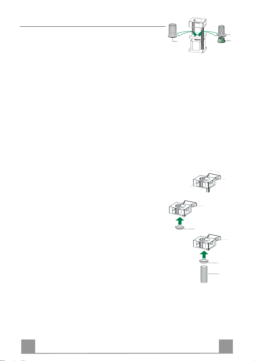
When installing the ducted version, connect the hood to the
chimney using either a flexible or rigid pipe ø 150 or 120 mm,
the choice of which is left to the installer.
• To install a ø 120 mm air exhaust connection, insert the reducer flange 9 on the hood body outlet.
• Fix the pipe using the pipe clamps 25 provided.
• Remove any activated charco al filters.
AIR OUTLET – RECIRCULATION VERSION
• Fasten the Air Outlet Connector 15 to the upper frame using
the 2 knobs 24.
• Attach the Air Outlet Connecto r Flange 14 to the Air Outlet
Connector 15.
• Connect the two outlets using the Air Outlet Connector Pipe
29.
Page 9
EN 113
Fitting the Chimney and Fixing the Hood Canopy
12c
12f
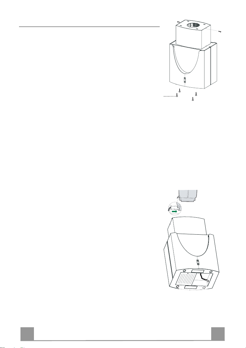
• Insert the Top chimney with the slots facing upwards when
installing the recirculation version, or vice versa with the slots
facing downwards when installing the ducting version, then fix
the top part to the Upper Chimney Connector using the screws
12c (2.9 x 9.5) provided.
Recirculation version
• Make sure that the Air Outlet Connector 15 is positioned in
correspondence with the Chimney Grill.
• If this is not the case, remove the chimney and adjust the position of the Air Outlet Connector 15; replace the components as
described above.
Before fixing the Hood Canopy to the Frame:
• Remove the metal grease filters from the hood canopy.
• Remove any activated charcoal odour filters.
• Fix t he hood canopy to the fra me provided, workin g from below and using the 4 screws 12f supplied.
ELECTRICAL CONNECTION
• Connect the hood to the mains through a two-pole switch having a contact gap of at least 3 mm.
• Re move the grease filters (see paragraph Maintenance) being
sure that the conn ector of the feeding cable is correctly inserted
in the socket placed on th e side of the fan.
• Join the connector s.
• Install the odour filter and the charcoal filter in case the hood is
to be used in recycling version.
• Install the grease filter again.
Page 10
EN 114
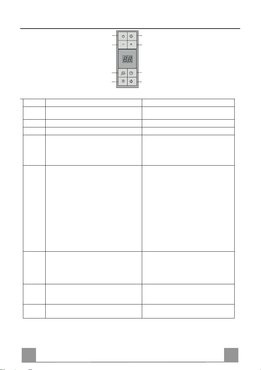
USE
A
B
D
C
E
GH
F
Control panel
Button Function Display
Turns the suction motor on and off at th e last
A
Displays the speed set
speed used.
B Decrease the working speed.
C Increase the working speed.
Activates intensive speed from any other
D
speed even wi th the motor off . This speed i s
Displays HI and the bottom right hand spot
flashes once a second.
timed to run for 10 minutes, after which the
system retu rns to th e previ ous sp eed. Su itable
to deal with maximum cooking fumes.
Activates the motor at a speed that allows
E
extraction of 100 m
3
/h for 10 minutes every
hour, after which the motor stops.
When the filt er alarm is on, pres s the button
for approximately 3 seconds to reset the
alarm. These indications are only visible
Displays 24 and the bottom right hand spot
flashes, while the motor is turned on
On completing the procedure the previous
indicator is turned off:
FF indicates that the metal grease filters
when the motor is turned off.
EF indicates that the activated charcoal
Activates automatic shutdown after 30’. Suit-
F
able to complete elimination of residual
odours. Can be activated from any position,
Alternately displays the working speed and
the time remaining before the hood turns
off. The bottom right hand spot flashes.
and is turned off by pressing the button or
switching the motor off.
Turns the lighting system (spots) on and off.
G
Press and hold for 2 sec onds to turn the Room
Lights on and off.
Turns the reduced intensity lighting system
H
(spots) on and off.
need washing. The alarm is triggered
after the Hood has been in operation
for 100 hours.
filter needs changing and the metal
grease filters need washing. The
alarm is triggered after the Hood has
been in operation for 200 hours.
Page 11
EN 115
MAINTENANCE
Metal grease filters
Filters can be washed in the dish machine. They need to be
washed when FF-sign appears on the display or in any case every
2 months, or even more frequently in case of particularly intensive use of the hood.
Alarm reset
• Switch off the hood and the lights. If the 24h-function has been
activated this has to be deactivated.
• Press the E-key till the display is unlit.
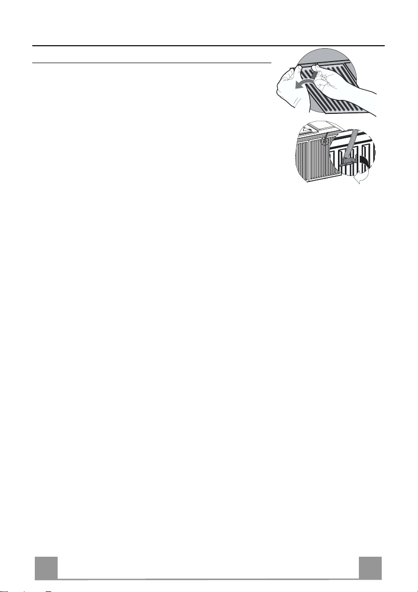
Cleaning the filters
• Unhook filters one by one. supporting the filters with one hand,
act on the knob (pull and rotate) and then take off the security
spring.
• Wash the filters, taking care not to bend them. Allow them to
dry before refitting.
• Reassemble the filters, paying attention on replacing the security spring.
Page 12
EN 116
Charcoal filter (recycling version)
• This filter cannot be washed or regenerated. It must be replaced when the EF appears on the
display or at least once every 4 months.
Activation of the alarm signal
• In the recycling version hoods the filter saturation alarm must be activated during the installation or later.
• Switch off the hood and the lights.
• Disconnect the hood from the mains supply.
• When restoring the connection press and hold B-key.
• When releasing the key t wo rotating rectangles appear on the display.
• Within 3 seconds press the B-key until a flashing confirmation appears on the dispaly:
• 2 flashes with EF - charcoal filter saturation alarm ACTIVATED
• 1 flash with EF - charcoal filter saturation alarm DEACTIVATED.
REPLACING THE CHARCOAL FILTER
Reset of the alarm signal
• Switch off the hood and the lighting. If the 24h-function has
been activated this has to be deactivated.
• Press the E-key until the display is unlit.
Replacing of the filter
• Remove the metal grease filters.
• Remove the saturated charcoal filter by releasing the fixing
hooks
• Fit the new filter and fasten it in its correct position.
• Put the metal grease filters in their seats.
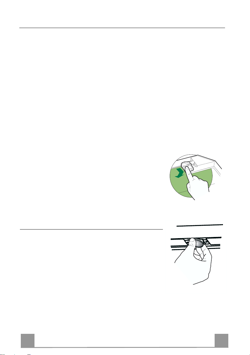
Lighting
LIGHT REPLACEMENT
20 W halogen light.
• Extract the lamp from the lamp holder by pulling gently.
• Replace with another of the same type, making sure that the
two pins are properly inserted in the lamp holder socket holes.
Page 13
EN 117
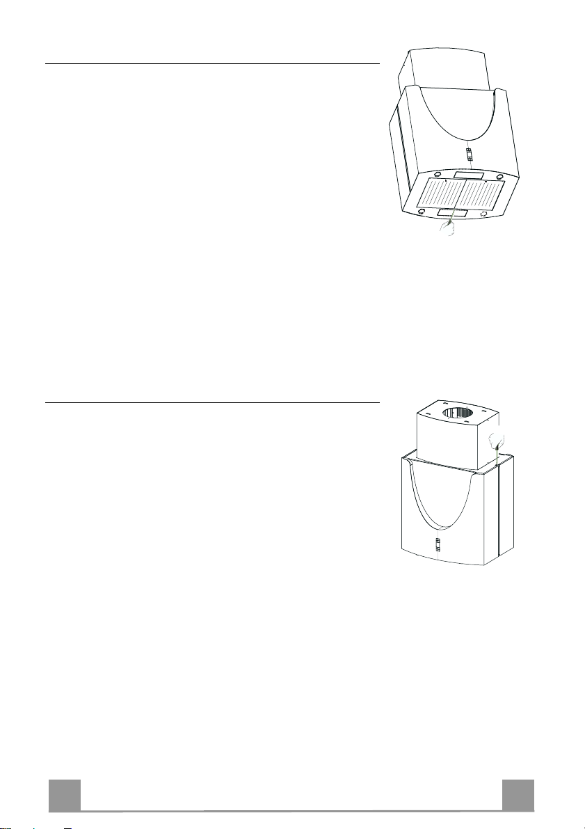
Lighting
CHANGING THE LAMPS
11W neon lamps
• Remove the Metal grease filters.
• Unfasten the screw fixing the Neon cover, and unhook the
cover from the hood canopy.
• Change the lamp and insert a new one of the same type.
• Replace the Cover.
• Replace the Metal grease filters.
Lighting
CHANGING A LED
• Unfasten the screws fixing the Led cover.
• Lift the cover and unfasten the connector.
• Remove the Led from the cover and replace it with a n ew one
of the same type.
• Fit the new Led in th e cov er, fast en u p th e conn ecto r again an d
replace the cover, using th e screws removed as above.
Page 14
The symbol on the product or on its packaging indicates that this pr o d uc t m ay n ot b e tr e ated as household waste. Ins tead it shall
be handed over to the appl icable col lection p oint for t he recycli ng of electr ical and el ectronic equipment . By ensurin g this product is
disposed of correctly, you will help prevent potential negative consequences for the environment and human health, which could otherwise be caused by inap propr iat e wast e ha ndl ing of this pro duc t. For mor e det ail ed inf ormati o n about recy cli ng of this pro duc t, ple ase
contact your local city office, your household waste disposal service or the shop where you purchased the product.
Il simbolo sul prodotto o sulla confezi on e indi ca che i l prodo tt o non d eve ess er e c onsid era to co me un n orm al e rifi uto d omes tic o,
ma deve essere port at o nel punt o di r acc olta appr opr iat o per il ric icl aggio di ap par ecchi atur e el ettr ich e ed el ettr oni ch e. Prov v ede nd o a
smaltire ques to pr od otto i n m odo a ppr opr iat o, s i contr ib uisc e a ev it are pote nzi ali c ons egu enz e ne gati ve per l’ ambi en te e p er l a salute,
che potrebber o d er i v are da uno smaltimento ina de guato del prodotto. Per i nf or m az i o ni pi ù dettagliate sul rici c l aggi o di questo prodotto,
contattare l’ufficio comunale, il servizio locale di smaltimento rifiuti o il negozio in cui è sta to acquistato il prodotto.
Le symbole sur le produit ou son embal la ge in diqu e que c e pr od uit ne peut ê tre tr ai té comm e déc he t mén ager . Il d oit pl utôt être
remis au point de ramassage concerné, se chargeant du recyclage du matériel électrique et électronique. En vous assurant que ce
produit est éli miné cor rectem ent, v ous fav orise z la prév entio n des cons équ ences né gativ es po ur l’env ironnem ent et l a sant é humaine
qui, sinon, serai e nt le résultat d’un traiteme nt inapproprié des déchets de ce produit. Pour obteni r pl us de dé tai ls sur le recyclage de ce
produit, veuillez prendre contact avec le bureau municipal de votre région, votre service d’élimination des déchets ménagers ou le
magasin où vous av ez acheté le produit.
Das Symbol auf dem Produkt oder s einer V erpac kung wei st dar auf hi n, dass di eses P rod ukt ni cht als norm aler Haus haltsa bfall
zu behandeln is t, so nder n an ei nem Sam mel pu nkt f ür das Rec ycl ing v on elek tri sc hen und elek tr onisc he n G eräte n abg egeb en w er den
muss. Durch Ihren Beitrag zum korr ek te n Entsorgen dieses Prod uk ts s chützen Sie die Umwelt und die Gesundheit Ihrer M i tm enschen.
Umwelt und Ges undheit werden durc h falsches Entsorge n gefährdet. Weitere Informationen über das Recycling dieses Pr odukts
erhalten Sie von Ihrem Rathaus, Ihrer Müllabfuhr oder dem Geschäft, in dem Sie das Produkt gekauft haben.
Ürün veya paketi üz erindeki sembolü, bu ürünün normal bir evsel atık olarak gör ülmemesi ve bu tip elek trikli veya elektr onik
cihazların at ıldığı dönüşümlü toplama noktal arına t erkedi lmes i gerek tiğine işaret e der. Bu ür ünü g erekti ği gibi elimi ne etme k urall arına
uyarsanız çevre ve insan sağlığı üzerindeki olumsuz etkilerini bert araf etmeye katkı s ağlamış olursunuz. Bu ür ünün geri dön üşüm
koşulları hakkında daha ayrıntılı bilgi için hudutları içinde bulunduğunuz belediyenin ilgili diaresine, atık yoketme servisine veya ürünün
satıcısına danışınız.
Franke S.p.a.
Via Pignolini,2
37019 Peschiera d el Garda (VR)
www.franke.it
436004079_ver2
 Loading...