

Page 1
Instructions for use and installation
Istruzioni per l’uso e l’installazione
Mode d’emploi et installation
Bedienungsanleitung und Installation
GB
Cooker Hood
IT
Cappa
FR
Hotte de Cuisine
DE
Dunstabzugshaube
FDF 9274 XS-CH FDF 12274 XS-CH
Page 2

INDEX
RECOMMENDATIONS AND SUGGESTIONS ..................................................................................................................... 3
CHARACTERISTICS ............................................................................................................................................................. 6
INSTALLATION ...................................................................................................................................................................... 7
USE ...................................................................................................................................................................................... 10
MAINTENANCE ................................................................................................................................................................... 11
EN
INDICE
CONSIGLI E SUGGERIMENTI ............................................................................................................................................ 13
CARATTERISTICHE ............................................................................................................................................................ 16
INSTALLAZIONE ................................................................................................................................................................. 17
USO ...................................................................................................................................................................................... 20
MANUTENZIONE................................................................................................................................................................. 21
IT
SOMMAIRE
CONSEILS ET SUGGESTIONS .......................................................................................................................................... 23
CARACTERISTIQUES ......................................................................................................................................................... 26
INSTALLATION .................................................................................................................................................................... 27
UTILISATION ....................................................................................................................................................................... 30
ENTRETIEN ......................................................................................................................................................................... 31
FR
INHALTSVERZEICHNIS
EMPFEHLUNGEN UND HINWEISE ................................................................................................................................... 33
CHARAKTERISTIKEN ......................................................................................................................................................... 36
MONTAGE ........................................................................................................................................................................... 37
BEDIENUNG ........................................................................................................................................................................ 40
WARTUNG ........................................................................................................................................................................... 41
DE
2
2
Page 3
EN
2°
RECOMMENDATIONS AND SUGGESTIONS
The Instructions for Use apply to several versions of this appliance.
Accordingly, you may find descriptions of individual features that do not
apply to your specific appliance.
INSTALLATION
•
The manufacturer will not be held liable for any damages resulting from
incorrect or improper installation.
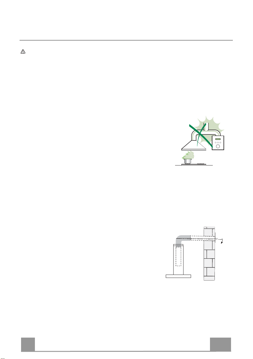
• The minimum safety distance between the cooker top
and the extractor hood is 650 mm (some models can
be installed at a lower height, please refer to the
paragraphs on working dimensions and installation).
• Check that the mains voltage corresponds to that
indicated on the rating plate fixed to the inside of the
hood.
• For Class I appliances, check that the domestic
power supply guarantees adequate earthing.
Connect the extractor to the exhaust flue through a pipe of minimum
diameter 120 mm. The route of the flue must be as short as possible.
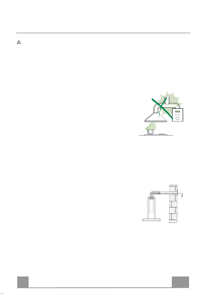
• Do not connect the extractor hood to exhaust ducts carrying combustion
fumes (boilers, fireplaces, etc.).
• If the extractor is used in conjunction with nonelectrical appliances (e.g. gas burning
appliances), a sufficient degree of aeration must
be guaranteed in the room in order to prevent the
backflow of exhaust gas. The kitchen must have
an opening communicating directly with the open
air in order to guarantee the entry of clean air.
When the cooker hood is used in conjunction with
appliances supplied with energy other than electric, the negative pressure in
the room must not exceed 0,04 mbar to prevent fumes being drawn back
into the room by the cooker hood.
• In the event of damage to the power cable, it must be replaced by the
manufacturer or by the technical service department, in order to prevent any
risks.
3
3
Page 4

EN
• If the instructions for installation for the gas hob specify a greater distance
specified above, this has to be taken into account. Regulations concerning
the discharge of air have to be fulfilled.
• Use only screws and small parts in support of the hood.
Warning: Failure to install the screws or fixing device in accordance with
these instructions may result in electrical hazards.
• Connect the hood to the mains through a two-pole switch having a contact
gap of at least 3 mm.
USE
•
The extractor hood has been designed exclusively for domestic use to
eliminate kitchen smells.
• Never use the hood for purposes other than for which it has been designed.
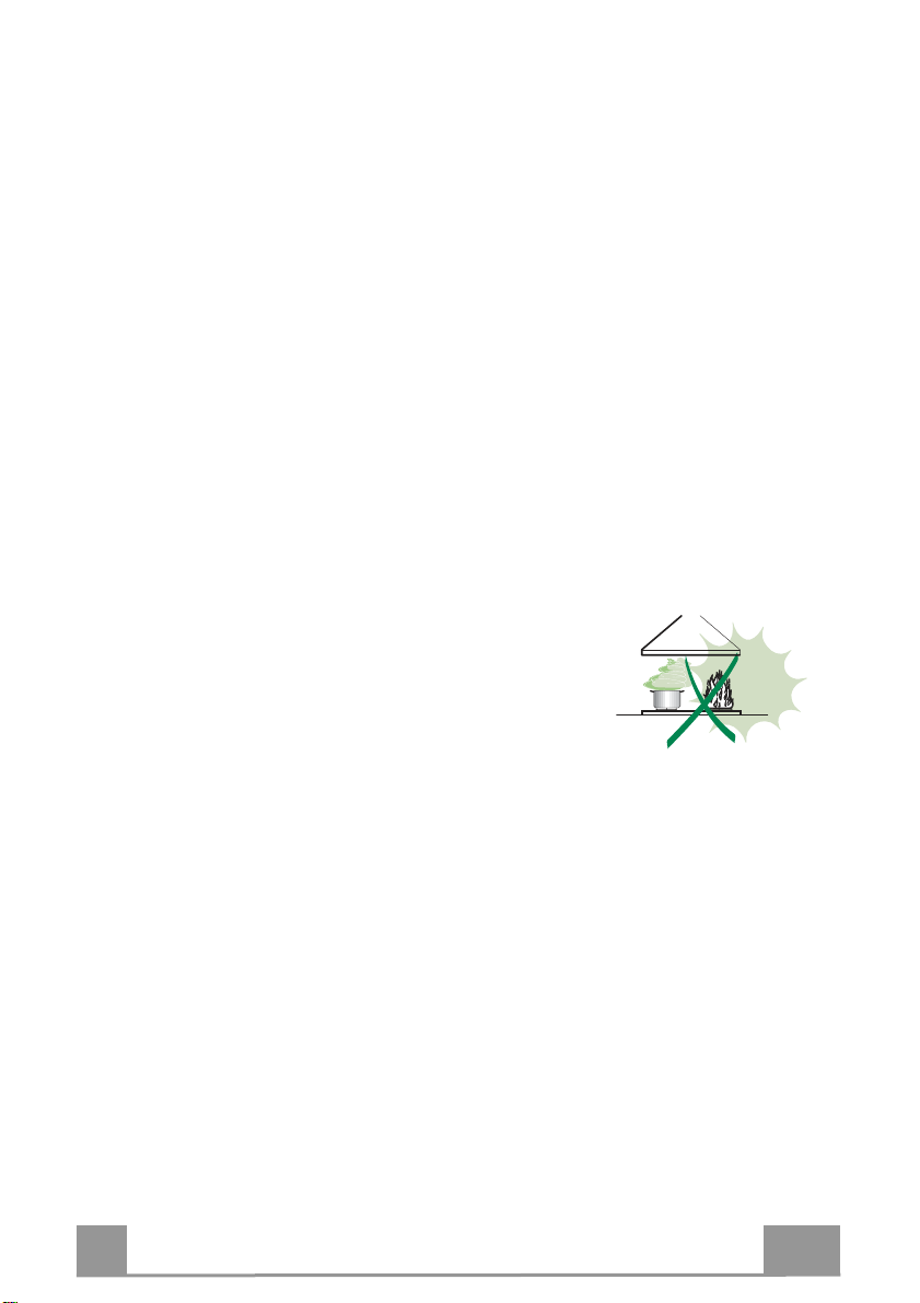
• Never leave high naked flames under the hood when it is in operation.
• Adjust the flame intensity to direct it onto the bottom of the pan only, making
sure that it does not engulf the sides.
• Deep fat fryers must be continuously monitored
during use: overheated oil can burst into flames.
• Do not flambè under the range hood; risk of fire.
• This appliance can be used by children aged from
8 years and above and persons with reduced
physical, sensory or mental capabilities or lack of
experience and knowledge if they have been given supervision or instruction
concerning use of the appliance in a safe way and understand the hazards
involved. Children shall not play with the appliance. Cleaning and user
maintenance shall not be made by children without supervision.
4
4
Page 5
EN
• “CAUTION: Accessible parts may become hot when used with cooking
appliances.”
MAINTENANCE
•
Switch off or unplug the appliance from the mains supply before carrying out
any maintenance work.
• Clean and/or replace the Filters after the specified time period (Fire hazard).
• The Grease filters must be cleaned every 2 months of operation, or more
frequently for particularly heavy usage, and can be washed in a dishwasher.
• The Activated charcoal filter is not washable and cannot be regenerated,
and must be replaced approximately every 4 months of operation, or more
frequently for particularly heavy usage.
• Clean the hood using a damp cloth and a neutral liquid detergent.
The symbol on the product or on its packaging indicates that this product
may not be treated as household waste. Instead it shall be handed over to the
applicable collection point for the recycling of electrical and electronic
equipment. By ensuring this product is disposed of correctly, you will help
prevent potential negative consequences for the environment and human
health, which could otherwise be caused by inappropriate waste handling of
this product. For more detailed information about recycling of this product,
please contact your local city office, your household waste disposal service or
the shop where you purchased the product.
5
5
Page 6
EN
64
42
81
Min.
650mm
Min.
650mm
545
730
1000
260
300
470 45
598-698-798-898-1198
108
150
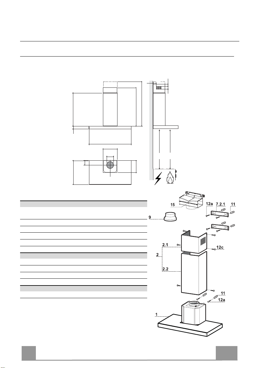
CHARACTERISTICS
Dimensions
Components
Ref. Q.ty Product Components
1 1 Hood Body, complete with: Controls, Light, Blower,
2 1 Telescopic Chimney comprising:
2.1 1 Upper Section
2.2 1 Lower Section
9 1 Reducer Flange ø 150-120 mm
15 1 Air Outlet Connection
Ref. Q.ty Installation Components
7.2.1 2 Upper Chimney Section Fixing Brackets
11 6 Wall Plugs
12a 6 Screws 4,2 x 44,4
12c 6 Screws 2,9 x 9,5
Q.ty Documentation
1 Instruction Manual
Filters
6
6
Page 7
EN
11
12a
305
X
116
1÷2
116
650 min.
7.2.1
INSTALLATION
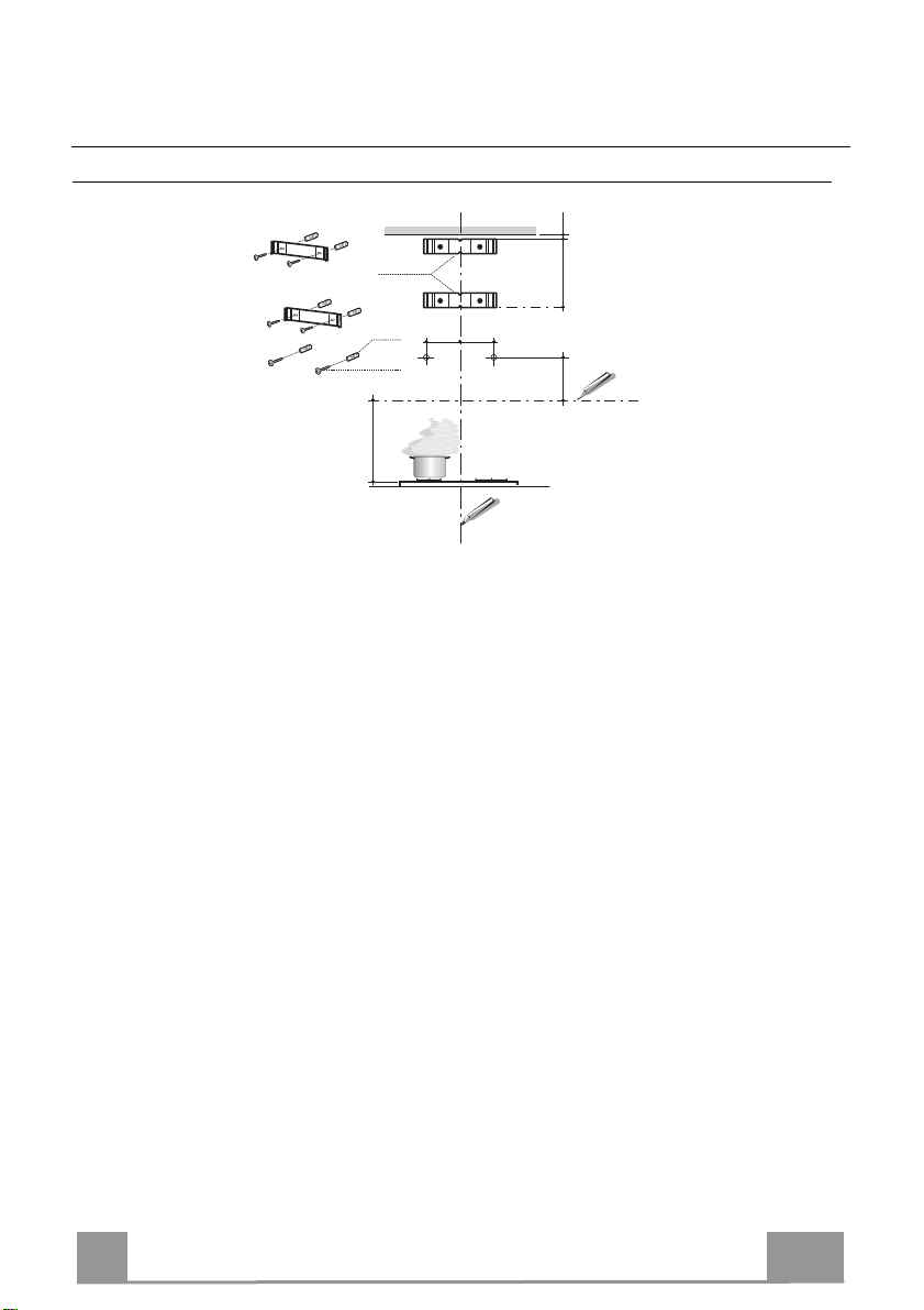
Wall drilling and bracket fixing
Wall marking:
• Draw a vertical line on the supporting wall up to the ceiling, or as high as practical, at the
centre of the area in which the hood will be installed.
• Draw a horizontal line at 650 mm above the hob. Place bracket 7.2.1 on the wall as shown
about 1-2 mm from the ceiling or upper limit aligning the centre (notch) with the vertical
reference line.
• Mark the wall at the centres of the holes in the bracket.
• Place bracket 7.2.1 on the wall as shown at X mm below the first bracket (X = height of the
upper chimney section supplied), aligning the centre (notch) with the vertical line.
• Mark the wall at the centres of the holes in the bracket.
• Mark a reference point as indicated at 116 mm from the vertical reference line and 305 mm
above the horizontal reference line.
• Repeat this operation on the other side.
• Drill ø 8 mm holes at all the centre points marked.
• Insert the wall plugs 11 in the holes.
• Fix the brackets using the 12a (4,2 x 44,4) screws supplied.
• Insert the two screws 12a (4,2 x 44,4) supplied in the hood body fixing holes, leaving a gap
of 5-6 mm between the wall and the head of the screw.
7
7
Page 8
EN
12a
Vr
9
ø 120ø 150
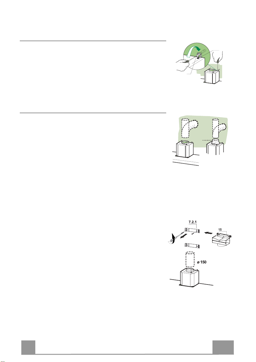
Mounting the hood body
• Before attaching the hood body, tighten the two screws Vr
located on the hood body mounting points.
• Hook the hood body onto the screws 12a.
• Fully tighten the support screws 12a.
• Adjust the screws Vr to level the hood body.
Connections
DUCTED VERSION AIR EXHAUST SYSTEM
When installing the ducted version, connect the hood to the
chimney using either a flexible or rigid pipe ø 150 or 120 mm,
the choice of which is left to the installer.
• To install a ø 120 mm air exhaust connection, insert the
reducer flange 9 on the hood body outlet.
• Fix the pipe in position using sufficient pipe clamps (not
supplied).
• Remove any activated charcoal filters.
AIR OUTLET – RECIRCULATION VERSION
• Unfasten the 2 screws fixing the upper bracket 7.2.1.
• Fasten the air outlet connector 15 in its place, using the 2
screws removed as above.
• Join the Connector 15 to the Hood canopy outlet using a rigid
or flexible pipe ø150 mm, selection of which is at the
discretion of the installation technician.
• Make sure that the Activated charcoal odour filter has been
fitted.
8
8
Page 9
EN
12c
2.1
2.2
2
7.2.1
12c
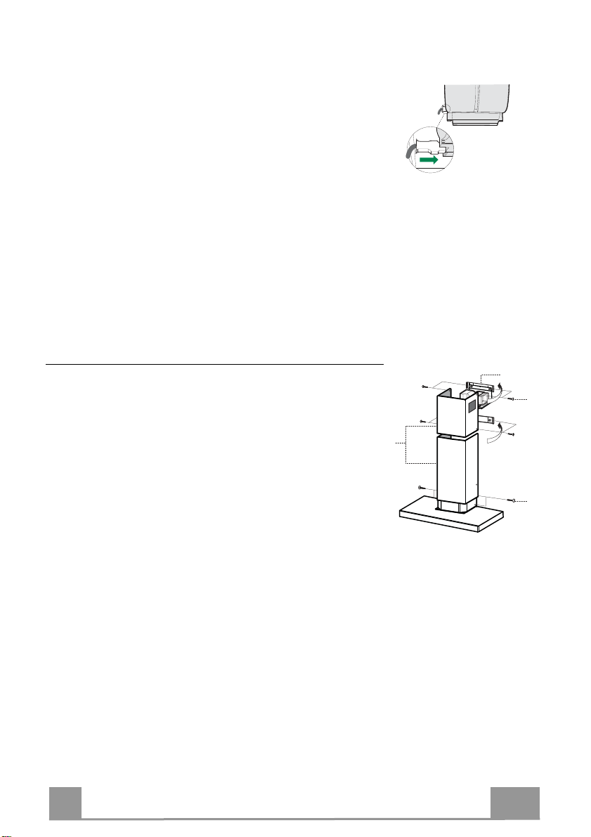
ELECTRICAL CONNECTION
• Connect the hood to the mains through a two-pole switch
having a contact gap of at least 3 mm.
• Remove the grease filters (see paragraph Maintenance) being
sure that the connector of the feeding cable is correctly inserted
in the socket placed on the side of the fan.
Flue assembly
Upper exhaust flue
• Slightly widen the two sides of the upper flue and hook them
behind the brackets 7.2.1, making sure that they are well
seated.
• Secure the sides to the brackets by using the 4 screws 12c (2,9
x 9,5) supplied.
• Make sure that the outlet of the extensions pieces is aligned
with the chimney outlets.
Lower exhaust flue
• Slightly widen the two sides of the flue and hook them
between the upper flue and the wall, making sure that they are
well seated.
• Fix the lower part laterally to the hood body by using the 2
screws 12c (2,9 x 9,5) supplied.
9
9
Page 10
EN
1
A B C D E F G H
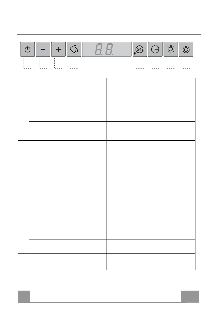
USE
Control panel
Button Function Display
A Turns the suction motor on and off at speed one. Displays the set speed
B Decreases the working speed. Displays the set speed
C Increases the working speed. Displays the set speed
D Activate intensive speed from any other speed,
including motor off. This speed is set to operate
for 6 minutes, after which the system returns to the
speed that was set before. Suitable to deal with
maximum levels of cooking fumes.
Press and hold the button for approximately 5
seconds, with all the loads turned off (Motor and
Lights), to turn the Activated Charcoal Filter
alarm On and Off.
E 24H function
Turns the suction motor on at speed one and
effects one 10 minute extraction every hour.
When the filters alarm is triggered, the alarm can
be reset by pressing and holding this button for
approximately 3 seconds.
These indications are only visible when the motor
is turned off.
F Delay function
Activate automatic switch-off with a 30’ delay.
Suitable to complete elimination of residual
odours. Can be activated from any position, and is
disabled by pressing the button or turning the
motor off.
Press and hold the button for approximately 5
seconds, with all the loads turned off (Motor and
Lights), to turn the Remote Control On and Off.
G Turns the lighting system on and off at maximum
intensity.
H Turns the Courtesy Lighting on and off.
Displays HI and the time remaining once very second.
FC+Dot (2 flashes)–Alarm On.
FC+Dot (1 flash)–Alarm Off.
Displays 24 and the spot at the bottom right flashes once
every second, while the motor is running.
It is disabled by pressing the button.
FF flashes three times.
When the procedure terminates, the indication shown
previously turns off:
FG indicates the need to wash the metal grease filters.
The alarm is triggered after the Hood has been in
operation for 100 working hours.
FC indicates the need to change the activated charcoal
filters, and also to wash the metal grease filters. The alarm
is triggered after the Hood has been in operation for 200
working hours.
Displays the operating speed and the spot at the bottom
right flashes once a second.
IR+Dot (2 flashes)–Alarm On.
IR+Dot (1 flash)–Alarm Off.
10
Page 11
EN
1
MAINTENANCE
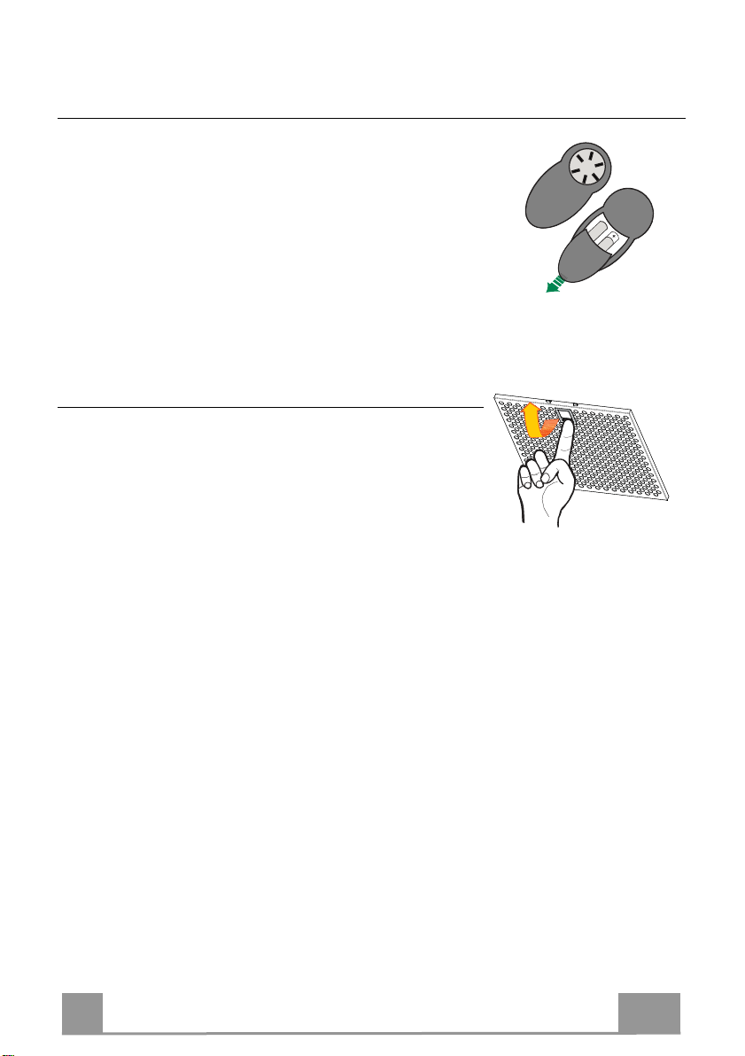
REMOTE CONTROL (OPTIONAL)
The appliance can be controlled using a remote control powered
by a 1.5 V carbon-zinc alkaline batteries of the standard LR03AAA type (not included).
• Do not place the remote control near to heat sources.
• Used batteries must be disposed of in the proper manner.
Metal grease filters
They can be washed in the dishwasher, and need to be cleaned
whenever the FG sign appears on the display or at least once
every 2 months use, or more frequently if use is particularly
intensive.
Resetting the alarm signal
• Turn the Lights and the Suction motor off, then disable the 24h
function, if enabled.
• Press button E (see the paragraph on Use).
Cleaning the Filters
• Remove the filters one at a time holding them up with one
hand and pulling the handle downwards with the other hand at
the same time.
• Wash the Filters without bending them, and leave them to dry
completely before replacing. (If the surface of the filter
changes colour as time goes by, this will have absolutely no
effect on the efficiency of the filter itself.)
• Replace, taking care to ensure that the handle faces forwards.
11
Page 12

EN
1
Activated Charcoal Filter (Recirculation Version)
It cannot be washed or regenerated, and must be changed when the FC symbol on the display
appears, or at least once every 4 months. The Alarm signal, if it has been activated, only
appears when the Suction motor is turned on.
Activating the alarm signal
• In Recirculation Version Hoods, the Filter Saturation Alarm must be activated on
installation or at a later date.
• Turn the Lights and the Suction Motor off.
• Press D and hold for approximately 5 Seconds:
• The message FC+Dot flashes twice, A.C. Filter saturation alarm ACTIVATED
• The message FC+Dot flashes once, A.C. Filter saturation alarm DEACTIVATED
CHANGING THE ACTIVATED CHARCOAL FILTER
Resetting the alarm signal
• Turn the Lights and the Suction motor off, then disable the 24h
function, if enabled.
• Press button E (see the paragraph on Use).
Changing the Filter
• Remove the Metal grease filters.
• Remove the saturated charcoal filter by releasing the fixing
hooks.
• Fit the new filter and fasten it in its correct position.
• Replace the Metal grease filters.
Lighting unit
Warning: This appliance is fitted with a white LED lamp classed
as 1M according to EN 60825-1: 1994 + A1:2002 + A2:2001
standards; maximum optical power emitted @439nm: 7µW. Do
not look directly at the light through optical devices (binoculars,
magnifying glasses…).
• For replacement contact technical support. ("To purchase
contact technical support")
12
Page 13
IT
1
2°
CONSIGLI E SUGGERIMENTI
Le Istruzioni per l’uso si riferiscono ai diversi modelli di questo
apparecchio. Pertanto, si potrebbero trovare descrizioni di singole
caratteristiche che non appartengono al proprio apparecchio specifico.
INSTALLAZIONE
•
Il fabbricante non potrà ritenersi responsabile per eventuali danni risultanti
da un’installazione o utilizzazione impropria.
• La distanza minima di sicurezza tra il piano cottura
e la cappa aspirante è di 650 mm (alcuni modelli
possono essere installati a un’altezza inferiore;
vedere il paragrafo relativo alle dimensioni di lavoro
e all'installazione).
• Controllare che la tensione di rete corrisponda a
quella indicata sulla targa dati applicata all’interno
della cappa.
• Per gli apparecchi di Classe I, controllare che la rete di alimentazione
domestica disponga di un adeguato collegamento a massa.
Collegare l'aspiratore al condotto dei fumi mediante un tubo con diametro
minimo di 120 mm. Il percorso dei fumi deve essere il più corto possibile.
• Non collegare la cappa aspirante ai condotti fumari che trasportano fumi di
combustione (per es. caldaie, camini ecc.).
• Se l’aspiratore è utilizzato in combinazione con
apparecchi non elettrici (per es. apparecchi a gas),
deve essere garantito un sufficiente grado di
aerazione nel locale per impedire il ritorno di flusso
dei gas di scarico. La cucina deve avere un'apertura
comunicante direttamente con l'esterno per garantire
l'afflusso di aria pulita. Quando la cappa per cucina è utilizzata in
combinazione con apparecchi non alimentati dalla corrente elettrica, la
pressione negativa nel locale non deve superare 0,04 mbar per evitare che i
fumi vengano riaspirati nel locale dalla cappa.
• In caso di danneggiamento del cavo di alimentazione, occorre farlo sostituire
dal produttore o dal reparto di assistenza tecnica per evitare qualsiasi
rischio.
13
Page 14
IT
1
• Se le istruzioni di installazione del piano cottura a gas specificano una
distanza maggiore di quella sopra indicata, è necessario tenerne conto.
Devono essere rispettate tutte le normative riguardanti lo scarico dell'aria.
• Usare solo viti e minuteria di tipo idoneo per la cappa.
Avvertenza: la mancata installazione delle viti o dei dispositivi di fissaggio in
conformità alle presenti istruzioni può comportare rischi di scosse elettriche.
• Collegare la cappa all'alimentazione di rete mediante un interruttore bipolare
con distanza tra i contatti di almeno 3 mm.
USO
•
La cappa aspirante è progettata esclusivamente per l’uso domestico allo
scopo di eliminare gli odori dalla cucina.
• Non usare mai la cappa per scopi diversi da quelli per cui è stata progettata.
• Non lasciare mai fiamme alte sotto la cappa quando è in funzione.
• Regolare l'intensità della fiamma in modo da dirigerla esclusivamente verso
il fondo del recipiente di cottura, assicurandosi che non ne avvolga i lati.
• Le friggitrici devono essere costantemente
controllate durante l’uso: l’olio surriscaldato
potrebbe incendiarsi.
• Non cuocere al flambé sotto la cappa: si potrebbe
sviluppare un incendio.
• Questo apparecchio può essere utilizzato da
bambini di età non inferiore a 8 anni e da persone con ridotte capacità psicofisico-sensoriali o con esperienza e conoscenze insufficienti, purché
attentamente sorvegliati e istruiti su come utilizzare in modo sicuro
l'apparecchio e sui pericoli che ciò comporta. Assicurarsi che i bambini non
giochino con l'apparecchio. Pulizia e manutenzione da parte dell'utente non
devono essere effettuate da bambini, a meno che non siano sorvegliati.
14
Page 15

IT
1
• “ ATTENZIONE: le parti accessibili possono diventare molto calde durante
l’uso degli apparecchi di cottura ”.
MANUTENZIONE
•
Spegnere o scollegare l’apparecchio dalla rete di alimentazione prima di
qualunque operazione di pulizia o manutenzione.
• Pulire e/o sostituire i filtri dopo il periodo di tempo specificato (pericolo di
incendio).
• I filtri antigrasso devono essere puliti ogni 2 mesi di funzionamento o più
frequentemente in caso di utilizzo molto intenso e possono essere lavati in
lavastoviglie.
• Il filtro al carbone attivo non è lavabile né è rigenerabile e deve essere
sostituito ogni 4 mesi di funzionamento circa o più frequentemente in caso di
utilizzo molto intenso.
• Pulire la cappa utilizzando un panno umido e un detergente liquido neutro.
Il simbolo sul prodotto o sulla sua confezione indica che il prodotto non
può essere smaltito come un normale rifiuto domestico. Il prodotto da smaltire
deve essere conferito presso un apposito centro di raccolta per il riciclaggio
dei componenti elettrici ed elettronici. Assicurandosi che questo prodotto sia
smaltito correttamente, si contribuirà a prevenire potenziali conseguenze
negative per l’ambiente e per la salute che potrebbero altrimenti derivare dal
suo smaltimento inadeguato. Per informazioni più dettagliate sul riciclaggio di
questo prodotto, contattare il Comune, il servizio locale di smaltimento rifiuti
oppure il negozio dove è stato acquistato il prodotto.
15
Page 16

IT
1
64
42
81
Min.
650mm
Min.
650mm
545
730
1000
260
300
470 45
598-698-798-898-1198
108
150
CARATTERISTICHE
Ingombro
Componenti
Rif. Q.tà Componenti di Prodotto
1 1 Corpo Cappa completo di: Comandi, Luce, Gruppo
2 1 Camino Telescopico formato da:
2.1 1 Camino Superiore
2.2 1 Camino Inferiore
9 1 Flangia di Riduzione ø 150-120 mm
15 1 Raccordo Uscita Aria
Rif. Q.tà Componenti di Installazione
7.2.1 2 Staffe Fissaggio Camino Superiore
11 6 Tasselli
12a 6 Viti 4,2 x 44,4
12c 6 Viti 2,9 x 9,5
Q.tà Documentazione
1 Libretto Istruzioni
Ventilatore, Filtri
16
Page 17

IT
1
11
12a
305
X
116
1÷2
116
650 min.
7.2.1
INSTALLAZIONE
Foratura Parete e Fissaggio Staffe
Tracciare sulla Parete:
• una linea Verticale fino al soffitto o al limite superiore, al centro della zona prevista per il
montaggio della Cappa;
• una linea Orizzontale a: 650 mm min. sopra il Piano di Cottura.
• Appoggiare come indicato la Staffa 7.2.1 a 1-2 mm dal soffitto o dal limite superiore,
allineando il suo centro (intagli) sulla linea Verticale di riferimento.
• Segnare i centri dei Fori della Staffa.
• Appoggiare come indicato la Staffa 7.2.1 a X mm sotto la prima staffa (X = altezza Camino
Superiore in dotazione), allineando il suo centro (intagli) sulla linea Verticale di riferimento.
• Segnare i centri dei Fori della Staffa.
• Segnare come indicato, un punto di riferimento a 116 mm dalla linea Verticale di
riferimento, e 305 mm sopra la linea Orizzontale di riferimento.
• Ripetere questa operazione dalla parte opposta.
• Forare ø 8 mm i punti segnati.
• Inserire i tasselli 11 nei fori.
• Fissare le Staffe, utilizzando le Viti 12a (4,2 x 44,4 ) in dotazione.
• Avvitare 2 Viti 12a (4,2 x 44,4) in dotazione nei fori per il fissaggio del corpo Cappa,
lasciando uno spazio di 5-6 mm fra la parete e la testa della vite.
17
Page 18

IT
1
12a
Vr
9
ø 120ø 150
Montaggio Corpo Cappa
• Prima di agganciare il Corpo Cappa, serrare le 2 Viti Vr situate
sui punti di aggancio del Corpo Cappa.
• Agganciare il Corpo Cappa alle Viti 12a.
• Serrare definitivamente le Viti 12a di supporto.
• Agire sulle Viti Vr per livellare il Corpo Cappa.
Connessioni
USCITA ARIA VERSIONE ASPIRANTE
Per installazione in Versione Aspirante collegare la Cappa alla
tubazione di uscita per mezzo di un tubo rigido o flessibile di
ø150 o 120 mm, la cui scelta è lasciata all'installatore.
• Per collegamento con tubo ø120 mm, inserire la Flangia di
riduzione 9 sull’Uscita del Corpo Cappa.
• Fissare il tubo con adeguate fascette stringitubo. Il materiale
occorrente non è in dotazione.
• Togliere eventuali Filtri Antiodore al Carbone attivo.
USCITA ARIA VERSIONE FILTRANTE
• Svitare le 2 Viti che fissano la Staffa Superiore 7.2.1.
• Avvitare al suo posto il Raccordo Uscita Aria 15 con le 2 viti
tolte in precedenza.
• Collegare il Raccordo 15 all’Uscita del Corpo Cappa per
mezzo di un tubo rigido o flessibile di ø150 mm, la cui scelta
è lasciata all'installatore.
• Assicurarsi della presenza del Filtro Antiodore al Carbone
attivo.
18
Page 19

IT
1
12c
2.1
2.2
2
7.2.1
12c
CONNESSIONE ELETTRICA
• Collegare la Cappa all’Alimentazione di Rete interponendo un
Interruttore bipolare con apertura dei contatti di almeno 3 mm.
• Rimuovere i Filtri antigrasso (vedi par. “Manutenzione”) e
assicurarsi che il connettore del Cavo di alimentazione sia
correttamente inserito nella presa dell’Aspiratore
Montaggio Camino
Camino superiore
• Allargare leggermente le due falde laterali, agganciarle dietro
le Staffe 7.2.1 e richiuderle fino a battuta.
• Fissare lateralmente alle Staffe con 4 Viti 12c (2,9 x 9,5) in
dotazione.
• Assicurarsi che l’uscita delle Prolunghe Raccordo risulti in
corrispondenza delle bocchette del Camino.
Camino inferiore
• Allargare leggermente le due falde laterali del Camino,
agganciarle tra il Camino superiore e la parete e richiuderle
fino a battuta.
• Fissare lateralmente la parte inferiore al Corpo Cappa, con 2
Viti 12c (2,9 x 9,5) in dotazione.
19
Page 20

IT
2
A B C D E F G H
USO
Quadro comandi
Tasto Funzione Display
A Accende e spegne il motore di aspirazione alla prima
velocità.
B Decrementa la velocità di esercizio. Visualizza la velocità impostata
C Incrementa la velocità di esercizio. Visualizza la velocità impostata
D Attiva la velocità Intensiva da qualsiasi velocità
anche da motore spento, tale velocità è temporizzata a
6 minuti, al termine del tempo il sistema ritorna alla
velocità precedentemente impostata. Adatta a
fronteggiare le massime emissioni di fumi di cottura.
Tenendo il tasto premuto per circa 5 secondi, quando
tutti i carichi sono spenti (Motore+Luce), si Attiva /
Disattiva l’allarme dei Filtri al Carbone attivo.
E Funzione 24H
Attiva il motore alla prima velocità e consente
un’aspirazione di 10 minuti ogni ora.
Con l’allarme filtri in corso premendo il tasto per
circa 3 secondi si effettua il reset dell’allarme.
Tali segnalazioni sono visibili solo a motore spento.
F Funzione Delay
Attiva lo spegnimento automatico ritardato di 30’.
Adatto per completare l’eliminazione di odori residui.
Attivabile da qualsiasi posizione, si disattiva premendo il tasto o spegnendo il motore.
Tenendo il tasto premuto per circa 5 secondi, quando
tutti i carichi sono spenti (Motore+Luce), si Attiva /
Disattiva il Telecomando.
G Accende e spegne l’impianto di illuminazione alla
massima intensità.
H Accende e spegne l’impianto di illuminazione in
modalità Luce di Cortesia.
Visualizza la velocità impostata
Visualizza alternamente HI e il tempo rimanente una
volta al secondo.
FC+Punto (2Lampeggi)–Allarme Attivo.
FC+Punto (1Lampeggio)–Allarme Disattivo.
Visualizza 24 e il punto in basso a destra lampeggia una
volta al secondo, mentre il motore è in funzione.
Si disabilita premendo il tasto.
Lampeggia FF tre volte.
Terminata la procedura si spegne la segnalazione
precedentemente visualizzata:
FG segnala la necessità di lavare i filtri antigrasso
metallici. L’allarme entra in funzione dopo 100 ore di
lavoro effettivo della Cappa.
FC segnala la necessità di sostituire i filtri al carbone
attivo e devono anche essere lavati i filtri antigrasso
metallici. L’allarme entra in funzione dopo 200 ore di
lavoro effettivo della Cappa.
Visualizza la velocità di esercizio e il punto in basso a
destra lampeggia una volta al secondo.
IR+Punto (2Lampeggi)–Allarme Attivo.
IR+Punto (1Lampeggio)–Allarme Disattivo.
20
Page 21

IT
2
MANUTENZIONE
TELECOMANDO (OPZIONALE)
Questo apparecchio può essere comandato per mezzo di un
telecomando, alimentato con pile alcaline zinco-carbone da 1,5 V
del tipo standard LR03-AAA (non incluse).
• Non riporre il telecomando in prossimità di fonti di calore.
• Non disperdere le pile nell’ambiente, depositarle negli appositi
contenitori.
Filtri antigrasso metallici
Sono lavabili anche in lavastoviglie, e necessitano di essere lavati
quando sul display appare FG o almeno ogni 2 mesi circa di
utilizzo o più frequentemente, per un uso particolarmente intenso.
Reset del segnale di allarme
• Spegnere le Luci e il Motore di aspirazione, quindi qualora
fosse attivata la funzione 24h disattivarla.
• Premere il tasto E (Vedi paragrafo Uso).
Pulizia Filtri
• Togliere i Filtri uno alla volta, sostenendoli con una mano
men-tre con l’altra si tira la leva verso il basso.
• Lavare i Filtri evitando di piegarli, e lasciarli asciugare prima
di rimontarli. (Un’eventuale cambiamento del colore della
superficie del filtro, che potrebbe verificarsi nel tempo, non
pregiudica assolutamente l’efficienza dello stesso.)
• Rimontarli facendo attenzione a mantenere la maniglia verso la
parte visibile esterna.
21
Page 22

IT
2
Filtri antiodore al Carbone attivo (Versione Filtrante)
Non è lavabile e non è rigenerabile, va sostituito quando sul display appare FC o almeno ogni
4 mesi. La segnalazione di Allarme, se preventivamente attivata, si verifica solo quando è
azionato il Motore di aspirazione.
Attivazione del segnale di allarme
• Nelle Cappe in Versione Filtrante, la segnalazione di Allarme saturazione Filtri va attivata al
momento dell’installazione o successivamente.
• Spegnere le Luci e il Motore di aspirazione.
• Premere il tasto D per circa 5 Secondi:
• 2 Lampeggi scritta FC+Puntino -- Allarme saturazione Filtro C.A. ATTIVATO.
• 1 Lampeggio scritta FC+Puntino -- Allarme saturazione Filtro C.A. DISATTIVATO.
SOSTITUZIONE FILTRO ANTIODORE AL CARBONE ATTIVO
Reset del segnale di allarme
• Spegnere le Luci e il Motore di aspirazione, quindi qualora
fosse attivata la funzione 24h disattivarla.
• Premere il tasto E (Vedi paragrafo Uso).
Sostituzione Filtro
• Togliere i Filtri antigrasso metallici.
• Rimuovere il Filtro antiodore al Carbone attivo saturo, agendo
sugli appositi agganci.
• Montare il nuovo Filtro agganciandolo nella sua sede.
• Rimontare i Filtri antigrasso metallici.
Illuminazione
Attenzione: Questo apparecchio è provvisto di una luce LED
bianca di classe 1M secondo la norma EN 60825-1: 1994 +
A1:2002 + A2:2001; massima potenza ottica emessa@439nm:
7µW. Non osservare direttamente con strumenti ottici (binocolo,
lente d’ingrandimento….).
• Per la sostituzione contattare l’Assistenza Tecnica. ("Per
l'acquisto rivolgersi all'assistenza tecnica").
22
Page 23

FR
2
2°
CONSEILS ET SUGGESTIONS
Les instructions pour l’utilisation se réfèrent aux différents modèles de cet
appareil. Par conséquent, certaines descriptions de caractéristiques
particulières pourraient ne pas appartenir spécifiquement à cet appareil.
INSTALLATION
•
En aucun cas le fabricant ne peut être tenu pour responsable d’éventuels
dommages dus à une installation ou à une utilisation impropre.
• La distance de sécurité minimum entre le plan de
cuisson et la hotte aspirante est de 650 mm (certains
modèles peuvent être installés à une hauteur inférieure ;
voir le paragraphe concernant les dimensions de travail
et l’installation).
• Assurez-vous que la tension de votre secteur correspond
à celle indiquée sur la plaque des données appliquée à
l’intérieur de la hotte.
• Pour les appareils de Classe I, s’assurer que l’installation électrique de votre
intérieur dispose d’une mise à la terre adéquate.
Relier l’aspirateur au conduit de cheminée avec un tube d’un diamètre minimum
de 120 mm. Le parcours des fumées doit être le plus court possible.
• Ne pas relier la hotte aspirante aux conduits de cheminée qui acheminent les
fumées de combustion (par exemple de chaudières, de cheminées, etc.).
• Si vous utilisez l’aspirateur en combinaison avec des
appareils non électriques (par ex. appareils à gaz), vous
devez garantir un degré d’aération suffisant dans la pièce,
afin d’empêcher le retour du flux des gaz de sortie. La
cuisine doit présenter une ouverture communiquant
directement vers l’extérieur pour garantir l’amenée d’air
propre. Si vous utilisez la hotte de cuisine en combinaison avec des appareils
non alimentés à l’électricité, la pression négative dans la pièce ne doit pas
dépasser 0,04 mbar afin d’éviter que la hotte ne réaspire les fumées dans la
pièce.
• Si le cordon d’alimentation est endommagé, veuillez le faire remplacer par le
fabricant ou par un service après-vente agréé pour éviter tout risque d’accident.
23
Page 24

FR
2
• Si les instructions d’installation du plan de cuisson à gaz spécifient une
distance supérieure à celle indiquée ci-dessus, veuillez impérativement en
tenir compte. Toutes les normes concernant l’évacuation de l’air doivent être
respectées.
• Utiliser exclusivement des vis et des petites pièces du type adapté pour la
hotte.
Attention : toute installation des vis et des dispositifs de fixation non
conforme aux présentes instructions peut entraîner des risques de
décharges électriques.
• Brancher la hotte à l’alimentation de secteur avec un interrupteur bipolaire
ayant une ouverture des contacts d’au moins 3 mm.
UTILISATION
• Cette hotte aspirante a été conçue exclusivement pour un usage
domestique, dans le but d’éliminer les odeurs de cuisine.
• Ne jamais utiliser la hotte pour des objectifs différents de ceux pour lesquels
elle a été conçue.
• Ne jamais laisser un feu vif allumé sous la hotte lorsque celle-ci est en
fonction.
• Régler l’intensité du feu de manière à l’orienter exclusivement vers le fond
de la casserole, en vous assurant qu’il ne déborde pas sur les côtés.
• Contrôler constamment les friteuses durant leur
utilisation : l’huile surchauffée risque de s’incendier.
• Ne pas flamber des mets sous la hotte : sous risque
de provoquer un incendie.
• Cet appareil n’est pas destiné à être utilisé par des
enfants d’un âge inférieur à 8 ans, ni par des personnes dont les capacités
physiques, sensorielles ou mentales sont diminuées ou qui ont une
expérience et des connaissances insuffisantes, à moins que ces enfants ou
ces personnes ne soient attentivement surveillés et instruits sur la manière
d’utiliser cet appareil en sécurité et sur les dangers que cela comporte.
Assurez-vous que les enfants ne jouent pas avec cet appareil. Le nettoyage
et l’entretien de la part de l’utilisateur ne doivent pas être effectués par des
enfants, à moins que ce ne soit sous la surveillance d’une personne
responsable.
24
Page 25

FR
2
• ATTENTION : les parties accessibles peuvent devenir très chaudes durant
l’utilisation des appareils de cuisson.
ENTRETIEN
•
Avant d’effectuer toute opération de nettoyage et d’entretien, éteindre ou
débrancher l’appareil du secteur.
• Nettoyer et/ou remplacer les filtres après le délai indiqué (danger
d’incendie).
• Nettoyer les filtres à graisse tous les 2 mois de fonctionnement ou plus
souvent en cas d’utilisation particulièrement intense. Ces filtres peuvent être
lavés au lave-vaisselle.
• Le filtre à charbon actif ne peut être ni lavé ni régénéré et il doit être
remplacé environ tous les 4 mois de fonctionnement ou plus souvent en cas
d’utilisation particulièrement intense.
• Nettoyer la hotte avec un chiffon humide et un détergent liquide neutre.
Le symbole marqué sur le produit ou sur son emballage indique que ce
produit ne peut pas être éliminé comme déchet ménager normal. Lorsque ce
produit doit être éliminé, veuillez le remettre à un centre de collecte prévu pour
le recyclage du matériel électrique et électronique. En vous assurant que cet
appareil est éliminé correctement, vous participez à prévenir des
conséquences potentiellement négatives pour l'environnement et pour la
santé, qui risqueraient de se présenter en cas d’élimination inappropriée. Pour
toute information supplémentaire sur le recyclage de ce produit, contactez
votre municipalité, votre déchetterie locale ou le magasin où vous avez acheté
ce produit.
25
Page 26

FR
2
64
42
81
Min.
650mm
Min.
650mm
545
730
1000
260
300
470 45
598-698-798-898-1198
108
150
CARACTERISTIQUES
Encombrement
Composants
Réf. Q.té Composants de Produit
1 1 Corps Hotte équipé de : Commandes, Lumière, Groupe
2 1 Cheminée Télescopique formée de :
2.1 1 Cheminée Supérieure
2.2 1 Cheminée Inférieure
9 1 Flasque de Réduction ø 150-120 mm
15 1 Raccord Sortie Air
Réf. Q.té Composants pour l ’installation
7.2.1 2 Brides Fixation Cheminée Supérieure
11 6 Chevilles
12a 6 Vis 4,2 x 44,4
12c 6 Vis 2,9 x 9,5
Q.té Documentation
1 Manuel d’instructions
Ventilateur, Filtres
26
Page 27

FR
2
11
12a
305
X
116
1÷2
116
650 min.
7.2.1
INSTALLATION
Perçage Paroi et Fixation Brides
Tracer sur la paroi:
• une ligne verticale allant jusqu’au plafond ou à la limite supérieure, au centre de la zone
prévue pour le montage de la hotte;
• une ligne horizontale à 650 mm min. au-dessus du plan de cuisson.
• Poser comme indiqué une bride 7.2.1 sur la paroi à 1-2 mm du plafond ou de la limite
supérieure, en alignant son centre (découpes) sur la ligne verticale de repère.
• Marquer les centres des trous rainurés de la bride.
• Poser comme indiqué la bride 7.2.1 à X mm sous la première bride (X = hauteur cheminée
supérieure fournie), en alignant son centre (découpes) sur la ligne verticale de repère.
• Marquer les centres des trous rainurés de la bride.
• Marquer comme indiqué, un point de référence à 116 mm de la ligne verticale de repère, et
305 mm au-dessus de la ligne horizontale de repère.
• Répéter cette opération sur le côté opposé.
• Percer de ø 8 mm tous les points marqués.
• Insérer les chevilles 11 dans les trous.
• Fixer les brides en utilisant les vis 12a (4,2 x 44,4) fournies.
• Visser les 2 vis 12a (4,2 x 44,4) fournies dans les trous de fixation du corps hotte, en laissant
un espace de 5-6 mm entre le mur et la tête de la vis.
27
Page 28

FR
2
12a
Vr
9
ø 120ø 150
Montage Corps Hotte
• Avant d’accrocher le corps hotte, serrer les deux vis Vr situées
sur les points d’accrochage du corps hotte.
• Accrocher le corps hotte aux vis 12a prévues à cet effet.
• Serrer définitivement les vis 12a de support.
• Agir sur les vis Vr pour niveler le corps hotte.
Branchements
SORTIE AIR VERSION ASPIRANTE
Pour l’installation en version aspirante, relier la hotte au tube de
sortie au moyen d’un tube rigide ou flexible de ø 150 ou 120 mm
dont le choix est laissé à l’installateur.
• Pour la liaison avec le tube ø120 mm, insérer la buse de
réduction 9 sur la sortie du corps de la hotte.
• Fixer le tube avec des colliers serre-tube appropriés. Le
matériel nécessaire n’est pas fourni.
• Retirer les filtres anti-odeur à charbon actif éventuels.
SORTIE AIR VERSION FILTRANTE
• Desserrer les 2 vis de fixation du support supérieur 7.2.1.
• Visser à sa place le raccord de sortie de l’air 15 avec les 2 vis
précédemment retirées.
• Relier le raccord 15 à la sortie du corps de hotte au moyen d’un
tube rigide ou flexible de ø 150 mm, au choix de l'installateur.
• S’assurer de la présence du filtre anti-odeur au charbon actif.
28
Page 29

FR
2
12c
2.1
2.2
2
7.2.1
12c
BRANCHEMENT ELECTRIQUE
• Brancher la hotte sur le secteur en interposant un interrupteur
bipolaire avec ouverture des contacts d’au moins 3 mm.
• Enlever les filtres à graisse (voir § "Entretien") et s'assurer que
le connecteur du câble d'alimentation soit bien branché dans la
prise du diffuseur.
Montage Cheminée
Cheminée supérieure
• Elargir légèrement les deux bords latéraux, et les accrocher
derrières les brides 7.2.1 ; refermer jusqu’en butée.
• Fixer latéralement aux brides à l’aide des 4 vis 12c fournies.
• S’assurer que la sortie des rallonges raccord se trouve au
niveau des bouches de la cheminée.
Cheminée inférieure
• Elargir légèrement les deux bords latéraux de la Cheminée et
les accrocher entre la Cheminée supérieure et la paroi; refermer
jusqu’en butée.
• Fixer latéralement la partie inférieure au corps de la hotte, à
l’aide des deux 2 vis 12c fournies.
29
Page 30

FR
3
A B C D E F G H
UTILISATION
Tableau de commande
Touche Fonction Affichage
A Branche et débranche le moteur d’aspiration à la
première vitesse
B Diminue la vitesse d’exercice. Affiche la vitesse réglée
C Augmente la vitesse d’exercice. Affiche la vitesse réglée
D Active la vitesse Intensive à partir de n’importe
quelle vitesse, même lorsque le moteur est éteint.
Cette vitesse est réglée pour une durée de 6 minutes,
après quoi le système retourne à la vitesse
précédemment réglée. Fonction indiquée pour faire
face aux pointes d’émission de fumées de cuisson.
Garder la touche appuyée pendant 5 secondes,
lorsque toutes les charges sont éteintes (Moteur+
Éclairage), l’alarme des filtres au charbon actif se
branche/se débranche.
E Fonction 24H
Active le moteur à la première vitesse et permet une
aspiration de 10 minutes par heure.
L’alarme filtres étant activée, appuyer sur la touche
pendant environ 3 secondes pour restaurer l’alarme.
Ces signalisations sont visibles seulement lorsque le
moteur est arrêté.
F Fonction Départ différé
Active le débranchement automatique différé de 30’.
Adapté pour compléter l’élimination d’odeurs
résiduelles. Activable à partir de n’importe quelle
position. Pour la désactiver, appuyer sur la touche ou
couper le moteur.
Garder la touche appuyée pendant 5 secondes,
lorsque toutes les charges sont éteintes (Moteur+
Éclairage), la télécommande se branche/se
débranche.
G Allume et éteint l’éclairage à l’intensité maximale.
H Branche et débranche l’éclairage en mode lumière de
courtoisie.
Affiche la vitesse réglée
Affiche alternativement HI et le temps restant une
fois par seconde
FC+Point (2 clignotements) – Alarme activée
FC+Point (1 Clignotement) – Alarme désactivée
Affiche 24 et le point en bas à droite clignote une fois
par seconde, alors que le moteur est en fonction.
Appuyer sur la touche pour débrancher.
FF clignote trois fois.
À la fin de la procédure, la signalisation
précédemment affichée s’éteint :
FG Signale la nécessité de laver les filtres à graisse
métalliques. L’alarme entre en fonction après 100
heures de travail effectif de la hotte.
FC Signale la nécessité de remplacer les filtres au
charbon actif. Laver également les filtres à graisse
métalliques. L’alarme entre en fonction après 200
heures de travail effectif de la hotte.
Affiche la vitesse d’exercice et le point en bas à
droite clignote une fois par seconde.
IR+Point (2 clignotements) – Alarme activée
FC+Point (1Clignotement) – Alarme désactivée
30
Page 31

FR
3
ENTRETIEN
TELECOMMANDE (FOURNIE SUR DEMANDE)
Il est possible de commander cet appareil au moyen d’une
télécommande, alimentée avec des piles alcalines zinc-charbon
1,5 V du type standard LR03-AAA (non compris).
• Ne pas ranger la télécommande à proximité de sources de
chaleur.
• Ne pas jeter les piles; il faut les déposer dans les récipients de
récolte spécialement prévus à cet effet.
Filtres à graisse métalliques
Ils sont lavables même au lave-vaisselle et ils doivent être lavés
chaque fois que le symbole FG s’affiche ou au moins tous les 2
mois d’utilisation ou plus souvent en cas d’utilisation
particulièrement intensive.
Reset du signal d'alarme
• Éteindre les lumières et le moteur d’aspiration ; au cas où la
fonction 24h serait activée, il convient de la désactiver.
• Appuyer sur la touche E (Voir paragraphe utilisation).
Nettoyage filtres
• Enlevez les filtres l’un après l’autre en les soutenant avec une
main et en tirant en même temps la poignée vers le bas avec
l’autre main.
• Laver les filtres en évitant de les plier et les laisser sécher avant
de les remonter (tout changement de couleur de la surface du
filtre, susceptible de se produire avec le temps, ne nuit en rien à
l’efficacité de ce dernier).
• Les remonter en veillant à ce que la poignée soit toujours vers
la partie visible externe.
31
Page 32

FR
3
Filtres anti-odeur au charbon actif (version filtrante)
Non lavable et non régénérable, il doit être remplacé à l’affichage de FC ou au moins tous les
4 mois. Le signal d’alarme, si préalablement activé, a lieu seulement lorsque le moteur
d’aspiration est en marche.
Activation du signal d’alarme
• Dans les hottes en version filtrante, activer le signal d’alarme de saturation filtres au
moment de l’installation ou après.
• Éteindre les lumières et le moteur d’aspiration.
• Appuyer sur la touche D pour environ 5 sec.
• 2 clignotements inscription FC+Point -- Alarme saturation Filtre C.A. ACTIVÉE
• 1 clignotement inscription FC+Point -- Alarme saturation Filtre C.A. DÉSACTIVÉE
REMPLACEMENT DU FILTRE ANTI-ODEUR AU CHARBON ACTIF
Reset du signal d'alarme
• Éteindre les lumières et le moteur d’aspiration ; au cas où la
fonction 24h serait active, il convient de la désactiver.
• Appuyer sur la touche E (Voir paragraphe utilisation).
Remplacement du filtre
• Retirer les filtres à graisse métalliques.
• Retirer le filtre anti-odeur au charbon actif saturé en agissant
sur les crochets qui le tiennent en place.
• Mettre le nouveau filtre en l’accrochant bien en place.
• Remonter les filtres à graisse métalliques.
Éclairage
Attention : Cet appareil est doté d’une lumière LED blanche de
classe 1M conformément à la norme EN 60825-1: 1994 +
A1:2002 + A2:2001 : puissance optique maximum émise à
439nm : 7µW. Ne pas observer directement avec des instruments
optiques (jumelles, lentilles grossissantes…)
• Pour le remplacement, contacter le Service après-vente.
(« Pour l’achat, s’adresser au service après-vente »).
32
Page 33

DE
3
2°
EMPFEHLUNGEN UND HINWEISE
Diese Gebrauchsanleitungen beziehen sich auf die verschiedenen Modelle
der Abzugshaube. Darum kann es möglich sein, dass die Beschreibung
bestimmter Merkmale für das vorliegende Gerät nicht zutrifft.
INSTALLATION
•
Der Hersteller haftet nicht für etwaige Schäden, die durch die fehlerhafte
Installation oder falschen Gebrauch entstehen könnten.
• Der min. Sicherheitsabstand zwischen Kochfeld
und Abzugshaube beträgt 650 mm (einige Modelle
können auch niedriger installiert werden; siehe
Absatz Installation).
• Kontrollieren Sie, ob die Netzspannung den Daten
des Typenschilds im Innern der Haube entspricht.
• Für Geräte der Klasse I muss kontrolliert werden,
ob das häusliche Versorgungsnetz korrekt geerdet
ist.
Die Absaughaube mit Hilfe eines Rohrs mit einem Mindestdurchmesser von
120 mm mit dem Rauchabzug verbinden. Der Verlauf des Rauchabzugs soll
so kurz wie möglich sein.
• Die Abzugshaube darf nicht an einen Schacht angeschlossen werden, in den
Rauchgase geleitet werden (z. B. von Heizkessel, Kaminen, usw.).
• Falls in dem Raum neben dem Abzug auch nicht
mit Strom betriebene Geräte (zum Beispiel
Gasgeräte) eingesetzt werden, muss für eine
ausreichende Belüftung gesorgt werden, damit der
Rückfluss der Abgase verhindert wird. Die Küche
muss eine direkte Öffnung nach Außen aufweisen,
damit ein ausreichender Luftaustausch
gewährleistet wird. Wird die Abzugshaube
zusammen mit nicht mit Strom betriebenen Geräte eingesetzt, darf der
Unterdruck im Raum 0,04 mbar nicht überschreiten, damit die Abgase nicht
wieder angesaugt werden.
• Schadhafte Kabel müssen durch den Hersteller oder vom Kundendienst
ausgewechselt werden, damit jedes Risiko ausgeschlossen wird.
33
Page 34

DE
3
• Falls die Montageanweisungen für die gasbetriebene Kochmulde einen
größeren Abstand vorschreiben, als der oben angegebene, muss diese
Vorgabe befolgt werden. Es sind sämtliche Abluftvorschriften zu beachten.
• Nur für die Abzugshaube geeignete Schrauben und Kleinteile verwenden.
Achtung: Werden die Schrauben und Befestigungselemente nicht
entsprechend der vorliegenden Anleitungen verwendet, besteht
Stromschlaggefahr.
• Die Abzugshaube mittels zweipoligem Schalter mit einer Öffnung der
Kontakte von mindestens 3 mm an das Netz anschließen.
GEBRAUCH
•
Die Abzugshaube wurde ausschließlich für den häuslichen Gebrauch
entwickelt, um Kochdünste zu beseitigen.
• Die Haube darf nur für die ihr zugedachten Zwecke benutzt werden.
Achtung! Große Flammen bei eingeschalteter Haube niemals
unbedeckt lassen.
• Die Flamme so regulieren, dass sie nicht über den Boden des Kochgeschirrs
hinausreicht.
Achtung! Frittiergeräte müssen während des Gebrauchs stets
beaufsichtigt werden: Überhitztes Öl kann sich entzünden.
• Auf keinen Fall unter der Haube flambieren: Brandgefahr.
• Kinder ab 8 Jahren und Personen mit
eingeschränkten physischen, sensorischen oder
psychischen Fähigkeiten, oder mit mangelnden
Erfahrungen oder Kenntnissen dürfen nicht mit
dem Gerät umgehen, es sei denn, sie werden von
einer für ihre Sicherheit verantwortlichen Person
beaufsichtigt oder angeleitet. Sicherstellen, dass Kinder nicht mit dem Gerät
herumspielen können. Reinigungs- und Wartungsarbeiten dürfen nicht von
unbeaufsichtigten Kindern durchgeführt werden.
34
Page 35

DE
3
• ACHTUNG: Die zugänglichen Teile können während des Gebrauchs der
Kochgeräte sehr heiß werden.
WARTUNG
•
Vor Reinigungs- oder Wartungsarbeiten am Gerät, muss dieses
ausgeschaltet und spannungslos gemacht werden.
• Die Filter stets nach den angegebenen Intervallen reinigen oder
auswechseln (Brandgefahr).
• Die Fettfilter sind alle 2 Monate oder bei intensiver Nutzung öfter zu reinigen
und können in der Spülmaschine gespült werden.
• Der Aktivkohlefilter ist weder waschbar, noch regenerierbar und muss bei
normalem Betrieb zirka alle 4 Monate oder auch öfter ausgewechselt
werden, je nach Intensität des Gebrauchs.
• Die Haube mit einem feuchten Lappen und einem neutralen
Reinigungsmittel abwischen.
Das Symbol am Produkt oder auf der Verpackung weist darauf hin, dass
das Gerät nicht als normaler Hausmüll entsorgt werden darf. Das ausrangierte
Gerät muss vielmehr bei einer speziellen Sammelstelle für elektrische und
elektronische Geräte abgegeben werden. Mit der vorschriftsmäßigen
Entsorgung des Gerätes trägt der Benutzer dazu bei, schädliche
Auswirkungen auf Umwelt und Gesundheit zu vermeiden. Weitere
Informationen zum Recycling dieses Produktes können bei der zuständigen
Behörde, der örtlichen Abfallbeseitigung oder bei dem Händler, der das Gerät
verkauft hat, eingeholt werden.
35
Page 36

DE
3
64
42
81
Min.
650mm
Min.
650mm
545
730
1000
260
300
470 45
598-698-798-898-1198
108
150
CHARAKTERISTIKEN
Platzbedarf
Komponenten
Pos. St. Produktkomponenten
1 1 Haubenkörper mit Schaltern, Beleuchtung,
2 1 Teleskopkamin bestehend aus:
2.1 1 oberer Kaminteil
2.2 1 unterer Kaminteil
9 1 Reduzierflansch ø 150-120 mm
15 1 Luftaustritt-Anschlussstück
Pos. St. Montagekomponenten
7.2.1 2 Befestigungsbügel oberer Kaminteil
11 6 Dübel
12a 6 Schrauben 4,2 x 44,4
12c 6 Schrauben 2,9 x 9,5
St. Dokumentation
1 Bedienungsanleitung
Gebläsegruppe, Filter
36
Page 37

DE
3
11
12a
305
X
116
1÷2
116
650 min.
7.2.1
MONTAGE
Bohren der Befestigungslöcher und Fixieren der Befestigungsbügel
Achtung: Bitte beachten Sie bei der Montage das Gewicht der kompletten Haube. Die
Tragfähigkeit der Decke oder alternativ der Trägerplatte für diese Zugbelastung muss vor der
Montage geprüft und gegebenenfalls durch die Anbringung von geeigneten Befestigungsoder Stabilisierungselementen hergestellt werden. Kann eine hinreichende Tragfähigkeit
nicht sichergestellt werden, ist von einer Montage abzusehen.
Nachstehende Linien an die Wand zeichnen:
• eine vertikale Linie bis zur Decke oder oberen Begrenzung, und zwar in der Mitte des
Bereiches, in dem die Haube montiert werden soll;
• eine horizontale Linie mit einem minimalen Abstand von 650 mm zur Kochfläche.
• Einen Bügel 7.2.1 zirka 1-2 mm unter der Decke oder oberen Begrenzung an die Wand
legen und seinen Mittelpunkt (Einschnitte) auf die vertikale Bezugslinie ausrichten.
• Die Mitte der beiden Bügellöcher an der Wand markieren.
• Den zweiten Bügel 7.2.1 an die Wand legen, wobei ein Abstand X mm vom oberen Bügel
einzuhalten ist (X = Höhe des jeweiligen oberen Kaminteils); den Mittelpunkt (Einschnitte)
auf die vertikale Bezugslinie ausrichten.
• Die Mitte der Bügellöcher an der Wand markieren.
• Wie beschrieben einen Bezugspunkt 116 mm von der vertikalen Bezugslinie und 305 mm
oberhalb der horizontalen Bezugslinie kennzeichnen.
• Gleichermaßen an der gegenüberliegenden Seite vorgehen.
• Mit einem Bohrer ø 8 mm die markierten Punkte bohren.
• Die Dübel 11 in die Bohrungen einfügen.
• Die Bügel mit den mitgelieferten Schrauben 12a (4,2 x 44,4) fixieren.
• 2 der mitgelieferten Schrauben 12a (4,2 x 44,4) bei den Befestigungslöchern des
Haubenkörpers einschrauben, wobei zwischen Wand und Schraubenkopf ein Freiraum von
5-6 mm zu belassen ist.
37
Page 38

DE
3
12a
Vr
9
ø 120ø 150
Montage des Haubenkörpers
• Bevor der Haubenkörper eingehakt wird, die 2 Schrauben Vr
bei den Haubenkörper-Anhakpunkten festziehen.
• Den Haubenkörper bei den Schrauben 12a einhängen.
• Die Halteschrauben 12a definitiv festziehen.
• Den Haubenkörper mit Hilfe der Schrauben Vr ausrichten.
Anschluss der Abluftversion
Bei Abluftbetrieb kann die Haube vom Installateur wahlweise
mittels Rohr oder Schlauch (ø 150 oder 120 mm) an die
Außenrohrleitung angeschlossen werden.
• Bei Verwendung eines Anschlussrohres ø 120 den
Reduzierflansch 9 am Haubenaustritt anbringen.
• Das Rohr mit geeigneten Rohrschellen fixieren. Das hierzu
erforderliche Material wird nicht mitgeliefert.
• Eventuell vorhandene Aktivkohlefilter entnehmen.
Achtung! Alle Querschnittänderungen oder
Richtungsänderungen des Abluftkanals reduzieren die
Leistung der Haube.
LUFTAUSTRITT BEI DER UMLUFTVERSION
• Die beiden Befestigungsschrauben des oberen Bügels 7.2.1.
aufschrauben.
• An ihrer Stelle mit den zuvor entfernten Schrauben ein
Anschlussstück an die Abzugsöffnung 15 anschrauben.
• Den Anschluss 15 mittels eines starren oder flexiblen Rohrs
mit ø150 mm, das vom Installateur ausgewählt wird, an den
Austritt des Haubenkörpers anschließen.
• Sicherstellen, dass der Aktivkohlefilter zur Geruchsbindung
vorhanden ist.
38
Page 39

DE
3
12c
2.1
2.2
2
7.2.1
12c
Elektroanschluss
Vor der Installation die Netzspannung durch herausdrehen der
Sicherung oder ausschalten des Hauptschalters stromlos
machen.
• Bei Anschluss der Haube an das Stromnetz muss ein
zweipoliger Schalter mit einem Öffnungsweg von
mindestens 3 mm zwischengeschaltet werden.
• Entfernen Sie die Fettfilter (s. Abschnitt „Wartung“) und
versichern Sie sich, daß die Kabelverbindung in die
Steckdose des Gebläses einwandfrei eingesteckt wird.
Achtung: Das Gerät nur an die Netzspannung die im
Typenschild angegeben ist anschließen.
Kaminmontage
Oberer Kaminteil
• Die beiden seitlichen Schenkel leicht auseinanderbiegen, hinter
den Bügeln 7.2.1 einhängen und bis zum Anschlag wieder
schließen.
• Bei den Bügeln 7.2.1 mit Hilfe der 4 mitgelieferten Schrauben
12c fixieren.
• Überprüfen, ob die Verlängerungen mit den entsprechenden
Kaminstutzen übereinstimmen.
Unterer Kaminteil
• Die beiden seitlichen Schenkel des Kaminteils leicht
auseinander biegen, zwischen dem oberen Kaminteil und der
Wand einhängen und bis zum Anschlag wieder schließen.
• Den unteren Teil seitlich am Haubenkörper mit 2 der
mitgelieferten Schrauben 12c fixieren.
39
Page 40

DE
4
A B C D E F G H
Taste Funktion
Display
A
B
C
D
FC+Pünktchen
E 24H Funktion:
24
FF
F Funktion Delay
Fernbedienung aktiviert / deaktiviert.
IR+Pünktchen
G
H
ein oder aus.
BEDIENUNG
Schalttafel
Schaltet den Absaugmotor bei der ersten
Geschwindigkeitsstufe ein und aus.
Vermindert die Betriebsgeschwindigkeit. Zeigt die eingestellte Geschwindigkeit an
Erhöht die Betriebsgeschwindigkeit. Zeigt die eingestellte Geschwindigkeit an
Aktiviert von jeder Geschwindigkeit aus, auch bei
abgestelltem Motor, die Intensivgeschwindigkeit, die
auf 6 Minuten zeitgeregelt ist. Nach Ablauf dieser Zeit
kehrt das System zu der zuvor eingestellten
Geschwindigkeit zurück. Für die Beseitigung von sehr
intensiven Kochdünsten geeignet.
Mit zirka 5 Sekunden langem Gedrückthalten der Taste
bei abgeschalteten Verbrauchern (Motor+Licht) wird der
Alarm der Aktivkohlefilter aktiviert / deaktiviert.
Aktiviert den Motor bei der ersten Geschwindigkeitsstufe
und ermöglicht eine Absaugung von 1 Minuten pro
Stunde.
Bei laufendem Filteralarm wird durch 3 Sekunden
anhaltendes Drücken der Taste ein Reset des Alarms
ausgelöst.
Derlei Anzeigen sind nur bei abgestelltem Motor sichtbar.
Aktiviert das automatische Ausschalten mit einer
Verzögerung von 30’. Vervollständigt die Beseitigung
von Restgerüchen. Kann von jeder Position aus
eingeschaltet werden und wird durch Drücken der Taste
oder Abstellen des Motors ausgeschaltet.
Mit zirka 5 Sekunden langem Gedrückthalten der Taste
bei abgeschalteten Verbrauchern (Motor+Licht) wird die
Schaltet die Beleuchtungsanlage auf höchster
Intensitätsstufe ein und aus.
Schaltet die Beleuchtung im Modus der Notbeleuchtung
Zeigt die eingestellte Geschwindigkeit an
Macht einmal pro Sekunde abwechselnd HI und die
Restzeit sichtbar.
FC+Pünktchen (1 Mal Blinken)–Alarm deaktiviert.
Zeigt
Sekunde, während der Motor in Betrieb ist
Wird durch Drücken der Taste deaktiviert.
blinkt drei Mal.
Nach abgeschlossener Prozedur verlöscht die bisherige
Anzeige:
FG zeigt an, dass der Metallfettfilter gewaschen werden
muss. Dieser Alarm wird nach 100 effektiven
Betriebsstunden der Abzugshaube ausgelöst.
FC zeigt an, dass die Aktivkohlefilter ausgewechselt
und die Metallfettfilter gewaschen werden müssen. Dieser
Alarm wird nach 200 effektiven Betriebsstunden der
Abzugshaube ausgelöst.
Zeigt die Betriebsgeschwindigkeit an und der Punkt unten
rechts blinkt einmal pro Sekunde.
IR+Pünktchen (1 Mal Blinken)–Alarm deaktiviert.
(2 Mal Blinken)–Alarm aktiviert.
an und der Punkt unten rechts blinkt einmal pro
(2 Mal Blinken)–Alarm aktiviert.
40
Page 41

DE
4
FERNBEDIENUNG (OPTIO
N)
WARTUNG
Dieses Gerät kann mit einer Fernbedienung gesteuert werden,
welche mit alkalischen Zink-Kohle-Batterien 1,5 V des
Standardtyps LR03-AAA versorgt wird (nicht im Lieferumfang
enthalten).
• Die Fernbedienung nicht in die Nähe von Hitzequellen legen.
• Batterien müssen vorschriftsmäßig entsorgt werden.
Metallfettfilter
Die Fettfilter sind spülmaschinengeeignet und müssen gewaschen
werden, sobald am Display die Aufschrift FG erscheint oder
mindestens alle 2 Monate, oder auch öfter, je nach Intensität des
Gebrauchs.
Reset des Alarmsignals
• Die Beleuchtung und den Absaugmotor abschalten und dann
die 24-Stunden-Funktion deaktivieren, falls diese zuvor aktiv
war.
• Die Taste E drücken (siehe Absatz GEBRAUCH).
Reinigung der Filter
• Einen Filter nach dem anderen entfernen. Halten Sie den Filter
mit einer Hand fest und ziehen Sie den Griff mit der anderen
Hand gleichzeitig nach unten.
• Die Filter waschen, ohne sie zu verbiegen, und vor dem
erneuten Einbau trocknen lassen. (Die Farbe der
Filteroberfläche kann sich mit der Zeit verändern, was aber die
Wirksamkeit keinesfalls beeinträchtigt.)
• Nun die Filter wieder einbauen, so dass der Griff nach der
äußeren Sichtseite zeigt.
41
Page 42

DE
4
Aktivkohle-Geruchsfilter (Umluftvariante)
Der Aktivkohlefilter ist nicht waschbar oder regenerierbar und muss ausgewechselt werden,
sobald am Display die Aufschrift FC erscheint, oder nach mindestens 4 Monaten. Die
Alarmmeldung, wenn zuvor aktiviert, erfolgt nur, wenn der Absaugmotor zugeschaltet ist.
Aktivierung des Alarmsignals
• Bei der Umluftvariante sollte die Alarmanzeige für die Filtersättigung bei der
Erstinbetriebnahme aktiviert werden. Zudem kann sie nachträglich wie folgt aktiviert
werden:
• Die Beleuchtung und den Absaugmotor abstellen.
• Die Taste D zirka 5 Sekunden lang drücken.
• Zwei Mal Blinken der Aufschrift FC+Pünktchen -- Alarm für Aktivkohlefiltersättigung
AKTIVIERT.
• Einmal Blinken der Aufschrift FC+Pünktchen -- Alarm für Aktivkohlefiltersättigung
DEAKTIVIERT.
AUSWECHSELN DES AKTIVKOHLE-GERUCHSFILTERS
Reset des Alarmsignals
• Die Beleuchtung und den Absaugmotor abschalten und dann die 24Stunden-Funktion deaktivieren, falls diese zuvor aktiv war.
• Die Taste E drücken (siehe Absatz GEBRAUCH).
Auswechseln des Filters
• Die Fettfilter aus Metall entfernen.
• Den gesättigten Aktivkohle-Geruchsfilter durch Öffnen der
Klammern ausbauen.
• Den neuen Filter in seinen Sitz einhängen.
• Die Fettfilter aus Metall wieder einbauen.
Beleuchtung
LED-Strahler
• Für den Austausch der LED-Strahler wenden Sie sich bitte an den
Kundendienst.
Achtung: Dieses Gerät ist mit einer weißen LED-Lampe der Klasse 1M
gemäß EN 60825-1 ausgestattet: 1994 + A1:2002 + A2:2001; max.
gelieferte Lichtleistung @439nm: 7µW. Nicht direkt mit optischen
Instrumenten (Fernglas, Lupe, usw.) in das Licht schauen.
42
Page 43

Page 44

Franke S.p.a.
Via Pignolini,2
37019 Peschiera del Garda (VR)
www.franke.it
991.0381.355_ver1
 Loading...