

Page 1

Instructions for use and installation
GB
Cooker Hood
Istruzioni per l’uso e l’installazione
IT
Cappa
Mode d’emploi et installation
FR
Hotte de Cuisine
Bedienungsanleitung und Einrichtung
DE
Dunstabzugshaube
Kullanım ve montaj talimatları
TR
Davlumbaz
FCBU 1204 C
Page 2

INDEX
RECOMMENDATIONS AND SUGGESTIONS ..................................................................................................................... 3
CHARACTERISTICS ............................................................................................................................................................. 4
CHARACTERISTICS ............................................................................................................................................................. 5
INSTALLATION...................................................................................................................................................................... 6
USE ........................................................................................................................................................................................ 9
MAINTENANCE................................................................................................................................................................... 11
EN
INDICE
CONSIGLI E SUGGERIMENTI............................................................................................................................................ 13
CARATTERISTICHE............................................................................................................................................................ 14
CARATTERISTICHE............................................................................................................................................................ 15
INSTALLAZIONE ................................................................................................................................................................. 16
USO...................................................................................................................................................................................... 19
MANUTENZIONE ................................................................................................................................................................ 21
SOMMAIRE
CONSEILS ET SUGGESTIONS.......................................................................................................................................... 23
CARACTERISTIQUES......................................................................................................................................................... 24
CARACTERISTIQUES......................................................................................................................................................... 25
INSTALLATION.................................................................................................................................................................... 26
UTILISATION .......................................................................................................................................................................29
ENTRETIEN......................................................................................................................................................................... 31
INHALTSVERZEICHNIS
EMPFEHLUNGEN UND HINWEISE ................................................................................................................................... 33
CHARAKTERISTIKEN......................................................................................................................................................... 34
CHARAKTERISTIKEN......................................................................................................................................................... 35
MONTAGE ...........................................................................................................................................................................36
BEDIENUNG........................................................................................................................................................................ 39
WARTUNG........................................................................................................................................................................... 41
IÇERIKLER
TAVSIYELER VE ÖNERILER.............................................................................................................................................. 43
ÖZELLIKLER........................................................................................................................................................................ 44
ÖZELLIKLER........................................................................................................................................................................ 45
MONTAJ............................................................................................................................................................................... 46
KULLANIM ........................................................................................................................................................................... 49
BAKIM .................................................................................................................................................................................. 51
IT
FR
DE
TR
2
2
Page 3
RECOMMENDATIONS AND SUGGESTIONS
650 mm min.
2°
The Instructions for Use apply to several versions of this appliance. Accordingly, you may find
descriptions of individual features that do not apply to you r specific appliance.
INSTALLATION
• The manufacturer will not be held liable for any damages resulting from incorrect or improper
installation.
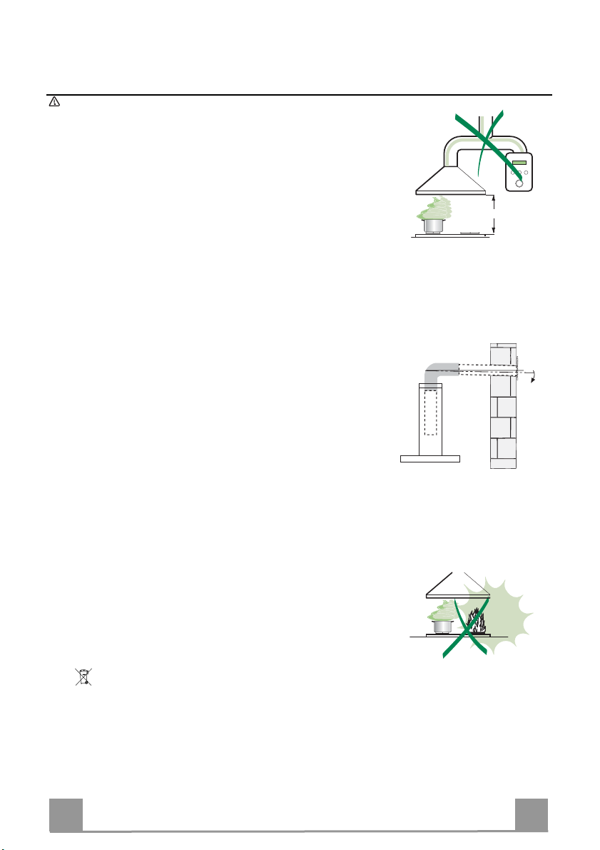
• The minimum safety distance between the cooker top and the extractor hood is 650 mm (some
models can be installed at a lower height, please refer to the paragraphs on working dimensions
and installation).
• Check that the mains voltage corresponds to that indicated on the rating plate fixed to the inside of
the hood.
• For Class I appliances, check that the domestic po wer supply guarantees adequate earthing.
Connect the extractor to the exhaust flue through a pipe of minimum diameter 120 mm. The route
of the flue must be as short as possible.
• Do not connect the extractor hood to exhaust ducts carrying combustion fumes (boilers, fireplaces,
etc.).
• If the extractor is used in conjunction with non-electrical appliances (e.g. gas burning appliances), a
sufficient degree of aeration must be guaranteed in the room in order to prevent the backflow of
exhaust gas. The kitchen must have an opening communicating directly with the open air in order
to guarantee the entry of clean air. When the cooker hood is used in conjunction with appliances
supplied with energy other than electric, the negative pressure in the room must not exceed 0,04
mbar to prevent fumes being drawn back into the room b y the cooker hood.
• In the event of damage to the power cable, it must be replaced by the manufacturer or by the
technical service department, in order to prevent an y risks.
• If the instructions for installation for the gas hob specify a greater distance specified above, this has
to be taken into account. Regulations concerning the discharge of air have to be fulfilled.
USE
• The extractor hood has been designed ex clusively for domestic use to eliminate kitchen smells.
• Never use the hood for purposes other than for wh ich it has been designed.
• Never leave high naked flames under the hood wh en it is in operation.
• Adjust the flame intensity to direct it onto the bottom of the pan only, making sure that it does not
engulf the sides.
• Deep fat fryers must be continuously monitor ed during use: overheated oil can burst into flames.
• Do not flambè under the range hood; risk of fire
• This appliance is not intended for use by persons (including children) with reduced physical, sensory or mental capabilities, or lack of experience and knowledge, unless they have been given supervision or instruction concerning use of the appli ance by a person responsible for their safety.
• Children should be supervised to ensure that they d o not play with the appliance.
• “ CAUTION: Accessible parts may become hot when use d with cooking appliances.”.
MAINTENANCE
• Switch off or unplug the appliance from the mains supply before carrying out any maintenance
work.
• Clean and/or replace the Filters after the specified ti me period (Fire hazard).
• Clean the hood using a damp cloth and a neutral liq uid detergent.
The symbol on the product or on its packaging indicates that thi s product may not be treated as household waste. Instead it shall be handed over to the
applicable collection point for the recy cling of electrical and electronic equipment . By ensuring this product is disposed of corre ctly, you will help prevent potential neg ative
consequences for the environment and h uman health, which could otherwise be cau sed by inappropriate waste handling of this product. For more detailed information
about recycling of this product, p lease contact your local city o ffice, your household waste disp osal service or the shop where you purchased the product
.
EN
3
3
Page 4
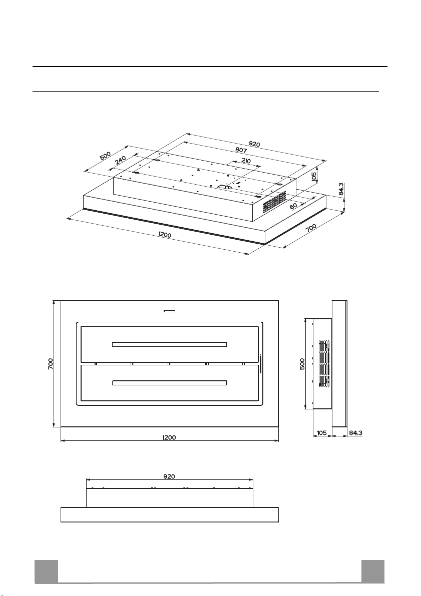
CHARACTERISTICS
Dimensions
EN
4
4
Page 5

Components
Ref. Q.ty Product Components
1 1 Hood Body, complete with: Controls, Light, Blower,
Filters.
2 Charcoal Filters.
Ref. Q.ty Installation Components
11 4 Wall Plugs ø 10
12g 4 Screws M6 x 80
12h 4 Screws 5,2 x 70
22 4 6.4 mm int. dia washers
23 4 M6 nuts
Q.ty Documentation
1 Instruction Manual
Fixing the Hood
• In all cases where the ceiling is not strong enough at the suspension point, the installer must
provide strengthening using suitable plates and backing pieces anchored to the structurally
sound parts.
2
EN
5
5
Page 6

INSTALLATION
Drilling the Ceiling/shelf and fixing the frame
DRILLING THE CEILING/SHELF
• Use a plumb line to mark the centre of the hob on the ceiling/support shelf.
• Using the measurements of the Dimensional Drawing, mark the holes for the installation.
• Drill the holes at the points marked:
• For concrete ceilings, drill for plugs appropriate to the screw size.
• For hollow brick ceilings with wall thickness of 20 mm: drill ø 10 mm(immediately insert
the Dowels 11 supplied).
• For wooden beam ceilings, drill according to the wood screws used.
• For wooden shelf, drill ø 7 mm.
• For the power supply cable feed, drill ø 10 mm.
• For the air outlet (Ducted Version), drill according to the diameter of the external air exhaust duct connection.
• Insert two screws of the following type, crossing them and leaving 4-5 mm from the ceiling:
• For concrete ceilings, use the appropriate plugs for the screw size (not provided).
• for Cavity ceiling with inner space, with wall thickness of approx. 20 mm, Screws 12h,
supplied.
• For wooden beam ceilings, use 4 wood screws (not provided).
• For wooden shelf, use 4 screws 12g with washers 22 and nuts 23, provided.
EN
6
6
Page 7

a
c d
e
b
6x
EN
4x
7
7
Page 8

ELECTRICAL CONNECTION
• Connect the hood to the mains through a two-pole switch having a contact gap of at least 3
mm..
•
Before carry
must be disconnected by removing the plug
from the power socket or turning off the
main switch.
• From the inside of the hood canopy connect
up the power supply cable.
• Open the terminal box by unfastening the
screws on cover (A), connect the power
supply to the wiring in the box and then
close the cover again.
Fix the Charcoal Filter on the Metal grease
•
filters like as indicated in picture.
ing out any operation the Hood
EN
8
8
Page 9

USE
LS1T1 T2 T3 T4
Control panel
Button Led Function
L - Turns the lights ON/OFF at maximum strength.
Press and hold for approx. 2 seconds to turn the lighting system on and off at reduced intensity.
T1 Fixed Turns the motor on/off at speed one.
T2 Fixed Turns the Motor on at speed two.
T3 Fixed Turns the Motor on at speed three.
T4 Fixed
S1 Fixed Signals the Metal Grease Filter saturation alarm, indicating that it is necessary to wash the filters. The
Flashing When this is activated, it signals the Activated Charcoal Filter saturation alarm, indicating that the filter
Delay function:
Press and hold the button for approx. 3 seconds to Activate/Deactivate the Delay function
(automatic switching off of the Motor, the Fans and the Lighting with a 30' delay).
Cannot be enabled when Intensive or 24h are on.
Press and hold the button for approximately 5 seconds, with all the loads turned off (Motor and Lights),
to turn the Activated Charcoal Filter alarm on. The relevant LED flashes twice to confirm.
To turn the alarm off, press the button again and hold for at least 5 seconds. The relevant LED flashes
once.
Press and hold the button for approximately 3 seconds, with all the loads turned off (Motor and Lights),
to perform a reset. The LED S1 flashes three times.
T
urns the Motor on
This speed is timed to run for 6 minutes. At the end of this time, the system returns automatically to the
speed that was set before. If it is activated with the motor turned off, it will switch to OFF at the end of
the time.
Press and hold for 5 seconds to enable the remote control, indicated by the LED flashing twice.
Press and hold for 5 seconds to disable the remote control, indicated by the LED flashing just once.
alarm is triggered after the Hood has been in operation for 100 working hours. (Reset see the parag.
Maintenance)
must be changed; the Metal Grease Filters must also be washed. The Activated Charcoal Filter saturation alarm comes into operation after the Hood has been working for 200 hours. (Activation and Reset
see the parag. Maintenance)
at INTENSIVE Speed.
EN
9
9
Page 10

REMOTE CONTROL
The appliance can be controlled using a remote control powered
by a 1.5 V carbon-zinc alkaline batteries of the standard LR03AAA type (not included).
• Do not place the remote control near to heat sources.
• Used batteries must be disposed of in the proper manner.
Remote control panel
Motor Motor On / Off.
Decreases the working speed each time it is pressed.
Increases the working speed each time it is pressed.
Intensive Activates the Intensive function
Delay Activates / Deactivates the Delay function
Light Lights On / Off
Press for 2 seconds to
modify the intensity of the Light.
EN
1
10
Page 11

MAINTENANCE
Metal grease filters
These can be washed in the dishwasher, and need to be cleaned
whenever the S1 Led comes on or at least once every 2 months
use, or more frequently if use is particularly intensive.
CLEANING THE FILTERS
Resetting the alarm signal
• Turn the Lights and the Suction Motor off.
• Press T3 and hold for at least 3 seconds, until LED flashes
three times in confirmation.
Cleaning the Filters
• Open the doors.
• Remove the Filter, pushing it towards the back of the unit and
at the same time pulling downward.
• Wash the filter without bending it, and leave it to dry thoroughly before replacing (if the surface of the filter changes
colour over time, this will have absolutely no effect on its efficiency).
• Replace, taking care to ensure that the handle faces forwards.
• Close the doors again.
EN
1
11
Page 12

Activated Charcoal Filter (Recirculation Version)
Can be washed in the dishwasher. It must be washed when Led S1 flashes or at least once
every 4 months, or more frequently if use is particularly intense. Guaranteed to operate after
washing for up to a maximum of 5 times before requiring replacement. The Alarm signal, if it
has been activated, only appears when the Suction motor is turned on.
Activating the alarm signal
• In Recirculation Version Hoods, the Filter Saturation Alarm must be activated on installation or at a later date.
• Turn the Lights and the Suction Motor off.
• Press button T2 and hold it for 5 seconds until the LED flashes twice in confirmation:
CHANGING
Resetting the alarm signal
• Turn the Lights and the Suction Motor off.
• Press T3 and hold for at least 3 seconds, until
LED flashes three times in confirmation.
Changing the Filter
• Open the doors.
• Remove the Metal Grease Filter.
• Remove the metal filter stops from the grease
filter and clean the saturated activated charcoal
odour filter.
• Replace the clean activated charcoal odour filter,
hooking it back up to the grease filter using the
metal filter stops.
• Replace the Metal grease filters.
• Close the doors.
Lighting unit
Warning: This appliance is fitted with a white LED lamp classed
as 1M according to EN 60825-1: 1994 + A1:2002 + A2:2001
standards; maximum optical power emitted @439nm: 7µW. Do
not look directly at the light through optical devices (binoculars,
magnifying glasses…).
• For replacement contact technical support. ("To purchase contact technical support")
EN
1
12
Page 13

Franke S.p.a.
Via Pignolini,2
37019 Peschiera del Garda (VR)
www.franke.it
991.0339.703_ver4
 Loading...