

Page 1
GB
IT
FR
DE
TR
DK
CZ
Instructions for use and installation
Cooker Hood
Istruzioni per l’uso e l’installazione
Cappa
Mode d’emploi et installation
Hotte de Cuisine
Bedienungsanleitung und Einrichtung
Dunstabzugshaube
Kullanım ve montaj talimatları
Davlumbaz
Betjenings- og installationsvejledning
Emhætte
Uživatelská Pøíruèka
Odsavač par
FAK 607
FAK 907
Page 2
INDEX
RECOMMENDATIONS AND SUGGESTIONS ..................................................................................................................... 4
CHARACTERISTICS ............................................................................................................................................................. 5
INSTALLATION...................................................................................................................................................................... 6
USE........................................................................................................................................................................................ 9
MAINTENANCE................................................................................................................................................................... 10
EN
INDICE
CONSIGLI E SUGGERIMENTI............................................................................................................................................ 13
CARATTERISTICHE............................................................................................................................................................ 14
INSTALLAZIONE ................................................................................................................................................................. 15
USO...................................................................................................................................................................................... 18
MANUTENZIONE ................................................................................................................................................................ 19
IT
SOMMAIRE
CONSEILS ET SUGGESTIONS.......................................................................................................................................... 22
CARACTERISTIQUES......................................................................................................................................................... 23
INSTALLATION.................................................................................................................................................................... 24
UTILISATION .......................................................................................................................................................................27
ENTRETIEN......................................................................................................................................................................... 28
FR
INHALTSVERZEICHNIS
EMPFEHLUNGEN UND HINWEISE ................................................................................................................................... 31
CHARAKTERISTIKEN......................................................................................................................................................... 32
MONTAGE ...........................................................................................................................................................................33
BEDIENUNG........................................................................................................................................................................ 36
WARTUNG........................................................................................................................................................................... 37
DE
IÇERIKLER
TAVSIYELER VE ÖNERILER.............................................................................................................................................. 40
ÖZELLIKLER........................................................................................................................................................................ 41
MONTAJ............................................................................................................................................................................... 42
KULLANIM ........................................................................................................................................................................... 45
BAKIM .................................................................................................................................................................................. 46
TR
INDHOLD
RÅD OG ANVISNINGER .....................................................................................................................................................49
APPARATBESKRIVELSE ................................................................................................................................................... 50
INSTALLATION.................................................................................................................................................................... 51
BRUG................................................................................................................................................................................... 54
VEDLIGEHOLDELSE .......................................................................................................................................................... 55
DK
2
2
Page 3

OBSAH
RADY A DOPORUČENÍ ...................................................................................................................................................... 58
HLAVNÍ PARAMETRY......................................................................................................................................................... 59
INSTALACE ......................................................................................................................................................................... 60
POUŽITÍ ............................................................................................................................................................................... 63
ÚDRŽBA............................................................................................................................................................................... 64
CZ
3
3
Page 4
RECOMMENDATIONS AND SUGGESTIONS
The Instructions for Use apply to several versions of this appliance. Accord-
ingly, you may find descriptions of individual features that do not apply to
your specific appliance.
INSTALLATION
• The manufacturer will not be held liable for any damages resulting from incorrect or improper installation.
• The minimum safety distance between the cooker top and the extractor
hood is 650 mm (some models can be installed at a lower height, please refer to the paragraphs on working dimensions and installation).
• Check that the mains voltage corresponds to that indicated on the rating
plate fixed to the inside of the hood.
• For Class I appliances, check that the domestic power supply guarantees
adequate earthing.
Connect the extractor to the exhaust flue through a pipe of minimum diame-
ter 120 mm. The route of the flue must be as short as possible.
• Do not connect the extractor hood to exhaust ducts carrying combustion
fumes (boilers, fireplaces, etc.).
• If the extractor is used in conjunction with non-electrical appliances (e.g. gas
burning appliances), a sufficient degree of aeration must be guaranteed in
the room in order to prevent the backflow of exhaust gas. The kitchen must
have an opening communicating directly with the open air in order to
guarantee the entry of clean air.
USE
• The extractor hood has been designed exclusively for domestic use to eliminate kitchen smells.
• Never use the hood for purposes other than for which it has been designed.
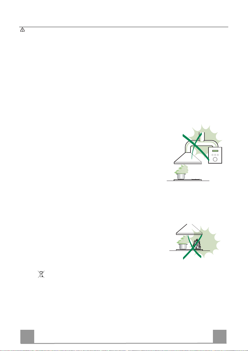
• Never leave high naked flames under the hood when it is in operation.
• Adjust the flame intensity to direct it onto the bottom of the pan only, making
sure that it does not engulf the sides.
• Deep fat fryers must be continuously monitored during use: overheated oil
can burst into flames.
• Do not flambè under the range hood; risk of fire
• This appliance is not intended for use by persons (including children) with
reduced physical, sensory or mental capabilities, or lack of experience and
knowledge, unless they have been given supervision or instruction concerning use of the appliance by a person responsible for their safety.
• Children should be supervised to ensure that they do not play with the appliance.
MAINTENANCE
• Switch off or unplug the appliance from the mains supply before carrying out
any maintenance work.
• Clean and/or replace the Filters after the specified time period (Fire hazard).
• Clean the hood using a damp cloth and a neutral liquid detergent.
The symbol on the product or on its packaging indicates that this product may not be treated
as household waste. Instead it shall be handed over to the applicable collection point for the
recycling of electrical and electronic equipment. By ensuring this product is disposed of correctly,
you will help prevent potential negative consequences for the environment and human health,
which could otherwise be caused by inappropriate waste handling of this product. For more
detailed information about recycling of this product, please contact your local city office, your
household waste disposal service or the shop where you purchased the product.
EN
4
4
Page 5
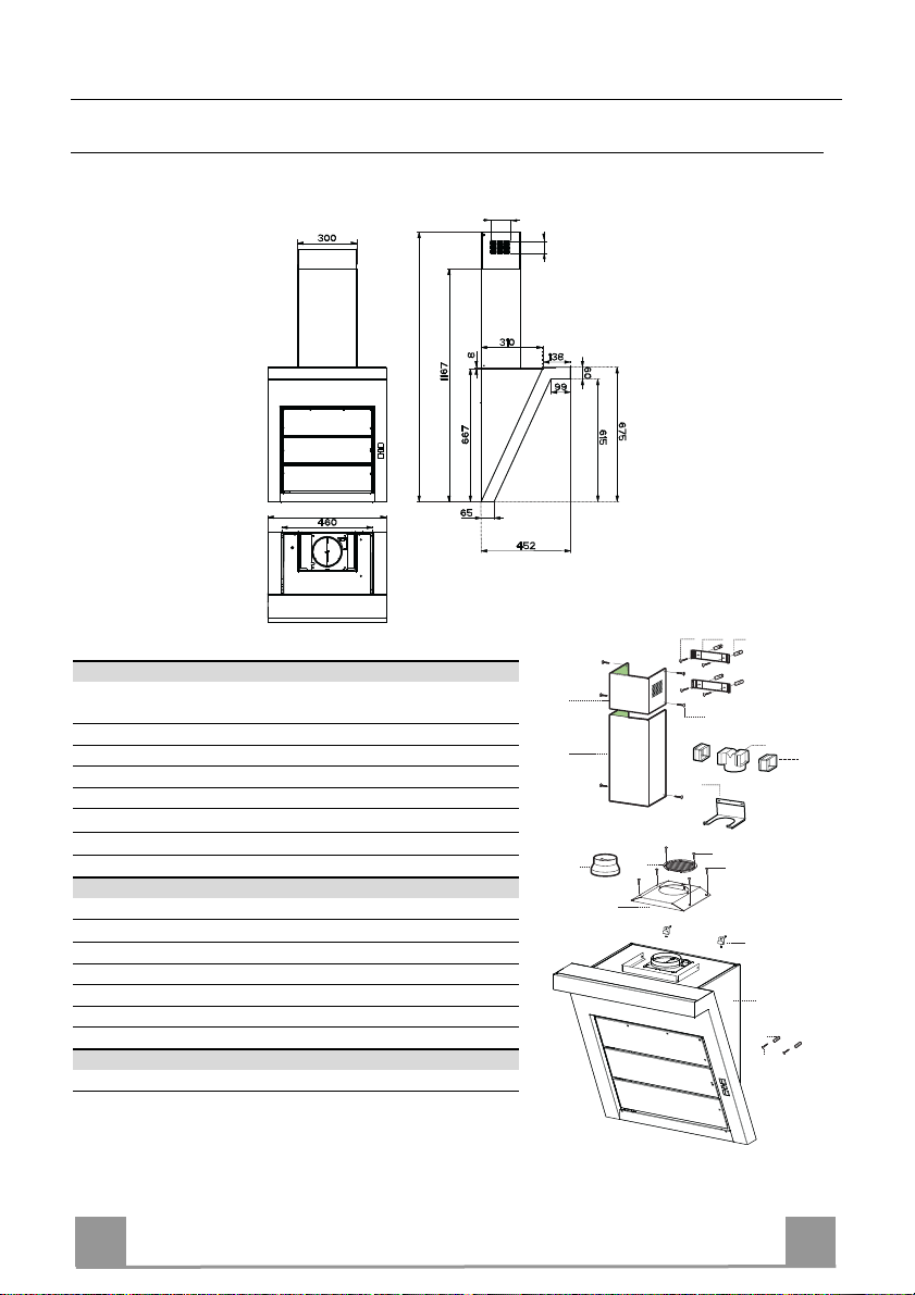
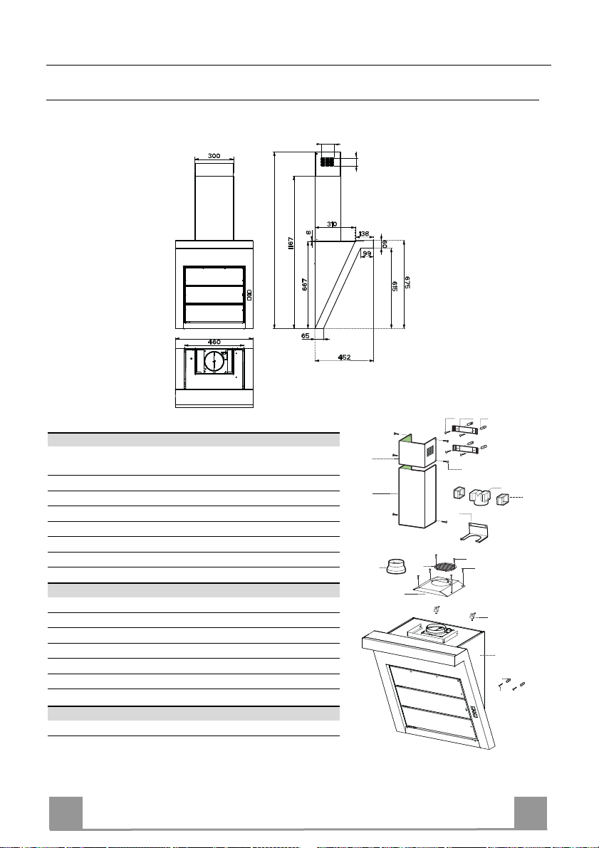
CHARACTERISTICS
Dimensions
126
Min.1305 - Max.1670
598 / 898
Components
Ref. Q.ty Product Components
1 1 Hood Body, complete with: Controls, Light, Blower,
Filters
2.1 1 Upper Section
2.2 1 Lower Section
8 1 Directional Air Outlet grille
9 1 Flange
14.1 2 Air Outlet Connection Extension
15 1 Air Outlet Connection
16 1 Filter cover
Ref. Q.ty Installation Components
7.2.1 2 Upper Chimney Section Fixing Brackets
7.3 1 Air Outlet Connection Support
11 6 Wall Plugs
11a 2 Wall Plugs SB 12/10
12a 6 Screws 4,2 x 44,4
12c 10 Screws 2,9 x 6,5
12d 2 Screws 2,9 x 9,5
Q.ty Documentation
1 Instruction Manual
81
12a
7.2.1 11
2.1
2.2
9
16
12c
15
14.1
7.3
12d
8
12c
11a
1
11
12a
EN
5
5
Page 6
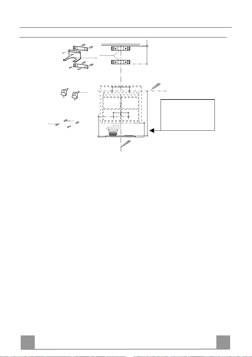
INSTALLATION
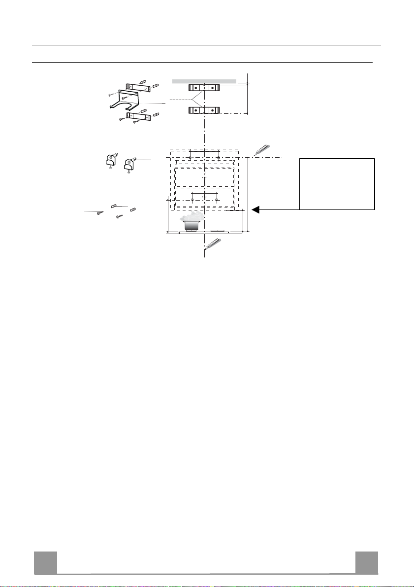
Wall drilling and bracket fixing
7.2.1
7.3
1÷2
X
11a
12a
11
190 190
11
190
22
362
Drilling measures
refer to a minimum
190
min. 250
max. 380
835
safety distance at
250 mm
On the wall, draw
• a Vertical line up to the ceiling or upper limit, at the centre of the area in which the Hood is
to be fitted;
• a Horizontal line at a minimum of 835 mm above the Cooker Top.
• Mark a point (1) on the horizontal line, 190 mm to the right of the vertical reference line.
• Repeat this operation on the other side, checking that the two marks are level.
• Mark a reference point (2) as indicated at 190 mm from the vertical reference line and 362
mm above the Cooker Top.
• Repeat this operation on the other side, checking that the two marks are level.
• Drill at the points (1) marked, using a ø 12 mm drill bit.
• Drill at the points (2) marked, using a ø 8 mm drill bit.
• Insert the bracket plugs 11a into the holes 1 and screw into place.
• Insert plug 11 into hole 2.
To install a decorative chimney ( optional )
• Place bracket 7.2.1 on the wall as shown about 1-2 mm from the ceiling or upper limit align-
ing the centre (notch) with the vertical reference line.
• Mark the wall at the centres of the holes in the bracket.
• Place bracket 7.2.1 on the wall as shown at X mm below the first bracket (X = height of the
upper chimney section supplied), aligning the centre (notch) with the vertical line.
• Mark the wall at the centres of the holes in the bracket.
• Drill ø 8 mm holes at all the centre points marked.
• Insert the wall plugs 11 in the holes.
• Fix the lower bracket 7.2.1 using the 12a screws (4,2 x 44,4) supplied.
• Fix the upper bracket 7.2.1 and the air outlet connection support 7.3 together using the 2
screws 12a (4,2 x 44,4) supplied.
EN
6
6
Page 7
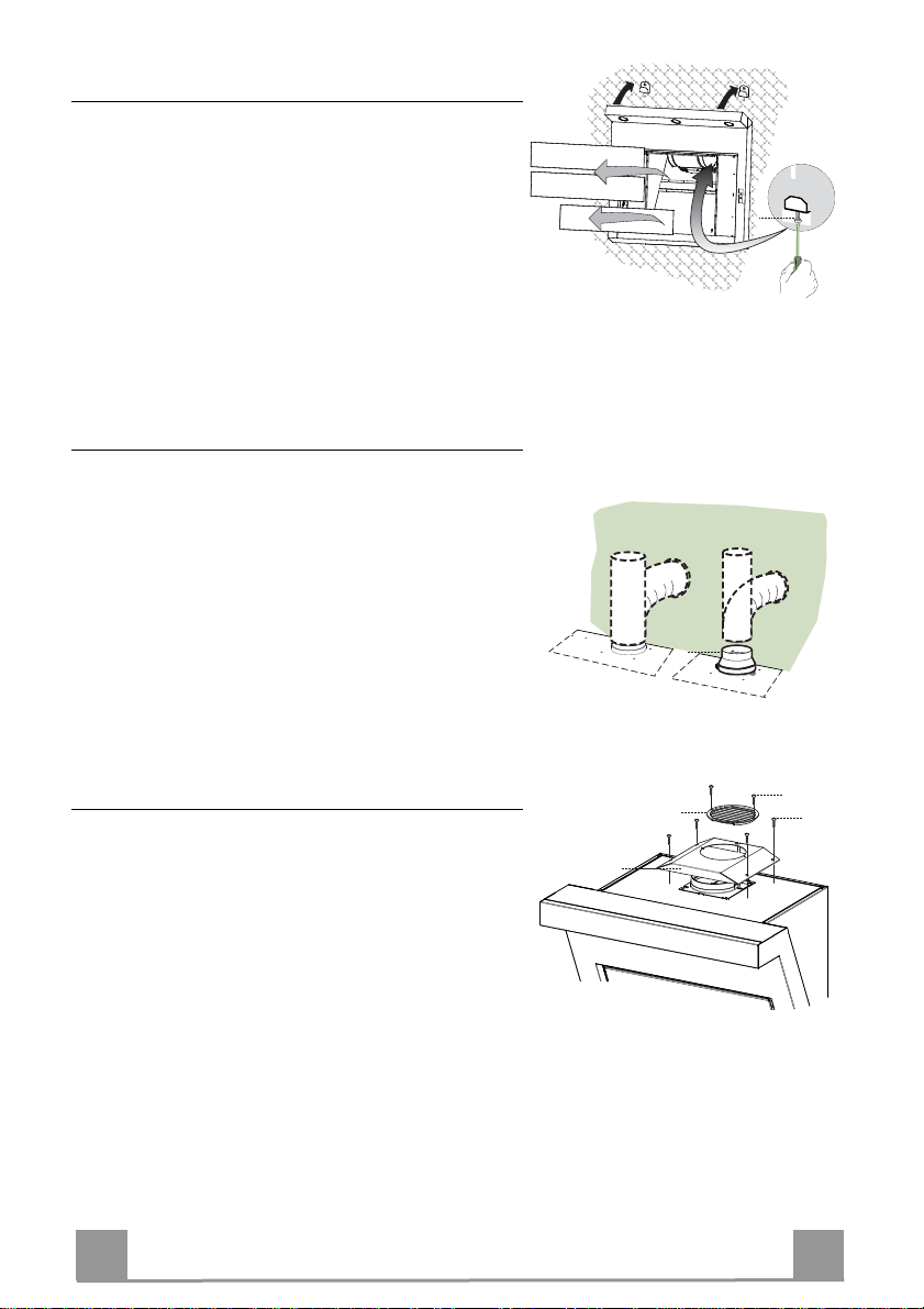
Mounting of the hood body
• Remove the comfort panels pulling them slightly
downwards.
• Remove the grease filters.
• Adjust slightly the Vr screws of the brackets 11a.
• Hang the hood body on the brackets 11a.
• It is possible to level the hood body, from inside the
hood, by adjusting the Vr screws.
• Tighten the security screws 11.
Connections
DUCTED VERSION AIR EXHAUST SYSTEM
When installing the ducted version, connect the hood to
the chimney using either a flexible or rigid pipe ø 150
or 120 mm, the choice of which is left to the installer.
• To install a ø 120 mm air exhaust connection, insert
the reducer flange 9 on the hood body outlet.
• Fix the pipe in position using sufficient pipe clamps
(not supplied).
• Remove any activated charcoal filters.
ø 150
Vr
ø 120
9
RECYCLING VERSION AIR OUTLET
To install the hood in recycling version, the optional
charcoal filter kit must be purchased.
• Remove the chimney angle bracket.
• Screw the filter cover onto the air outlet, using four
screws 12c (2.9 x 12.5).
• Fix the air outlet grid 8 on the recirculation air outlet
using the 2 screws 12d (2,9 x 9,5) provided.
EN
8
16
12d
12c
7
7
Page 8
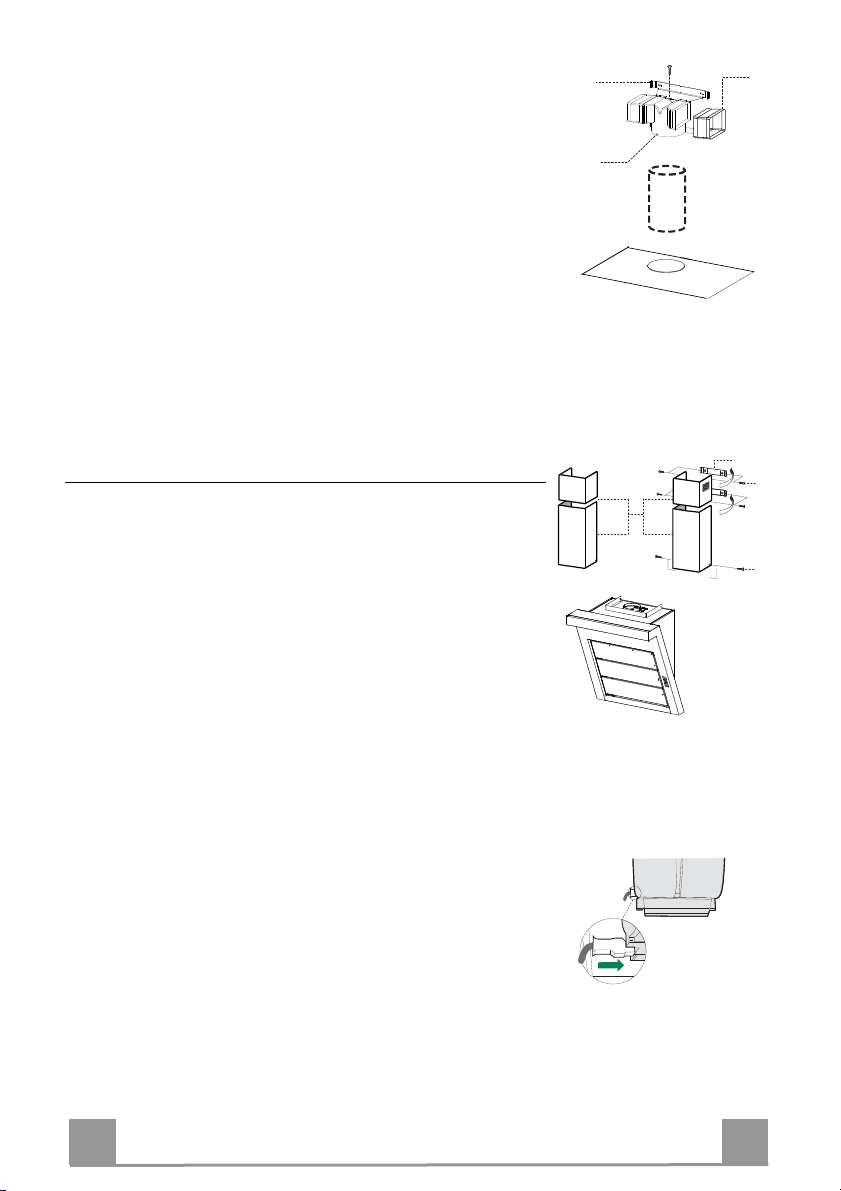
RECIRCULATION VERSION AIR OUTLET
15
ø 150
14.1
7.3
2.1
2.2
2
7.2.1
12c
12c
2.1
2.2
• Insert the connection extension pieces laterally 14.1 in connection 15.
• Insert the Connector 15 into the Support bracket 7.3 and fix it
with a screw.
• Make sure that the outlet of the extension pieces 14.1 is horizontally and vertically aligned with the chimney outlets.
• Connect the air outlet connection 15 to the hood body outlet
using either a flexible or rigid pipe ø 150 mm, the choice of
which is left to the installer.
• Ensure that the activated charcoal filters have been inserted.
Chimney assembly
Upper exhaust Chimney
• Slightly widen the two sides of the upper chimney and hook
them behind the brackets 7.2.1, making sure that they are well
seated.
• Secure the sides to the brackets using the 4 screws 12c (2,9 x
9,5) supplied.
Lower exhaust Chimney
• Slightly widen the two sides of the chimney and hook them
between the upper chimney and the wall, making sure that they
are well seated.
• Fix the lower part laterally to the hood body using the 2 screws
12c (2,9 x 9,5) supplied.
ELECTRICAL CONNECTION
• Connect the hood to the mains through a two-pole switch having a contact gap of at least 3 mm.
• Remove the grease filters (see paragraph Maintenance) being
sure that the connector of the feeding cable is correctly inserted
in the socket placed on the side of the fan.
EN
8
8
Page 9
USE
A
B
D
C
E
GH
F
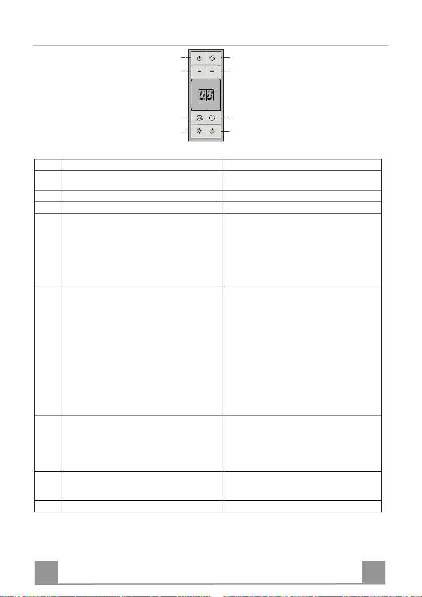
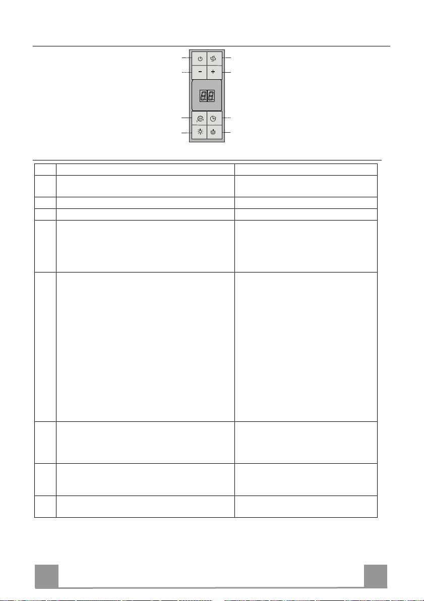
Control board
Key Function Display
Switches the extractor motor on and off at the latest
A
Indicates the selected speed.
selected speed
Decreases the suction speed.
B
Increases the suction speed.
C
By pressing this key it is possible to activate the
D
intensive speed from any previously selected speed.
The intensive speed can be activated even when
HI appears. The spot down on the right side flashes
once a second.
the motor is OFF. This speed has been timed at 10
minutes. After that time the system activates automatically the latest selected speed. This function is
suitable for cooking conditions when vapours and
smells are of the utmost emission.
E By pressing this key it is possible to set up the motor
to a suction speed at 100 m
3
/h lasting 10 minutes
every hour. After this the motor switches off automatically.
When the filter saturation is going on it is possible to
reset the alarm by pressing this key for about 3 sec-
Indicates the 24-function. The spot down on the
right side flashes and the motor is on.
Once the process is finished the previous indication
disappears:
FF Indicates that the metal grease filters satura-
onds. The indication is visible only when the motor
is off.
By pressing this key it is possible to set the delayed
F
shutdown of the appliance to 30 minutes. This function is suitable for a complete elimination of the residual smells. It can be activated at any position,
EF Indicates that the charcoal filter saturation
Indicates alternately the selected speed of the hood
and the time left before the hood shutdown. The
spot down on the right side flashes.
and it is deactivated by pressing the key again or by
switching off the motor.
Turns light on and off .
G
When pressed for about 2 seconds the upper lighting switches on (only in the 90 cm hood version).
Turns light on and off at reduced intensity.
H
tion alarm has been triggered, and the filters
need to be washed. The alarm is triggered after 100 working hours.
alarm has been triggered, and the filter has to
be replaced; the metal grease filters must
also be washed. The charcoal filter is triggered after 200 working hours.
EN
9
9
Page 10

MAINTENANCE
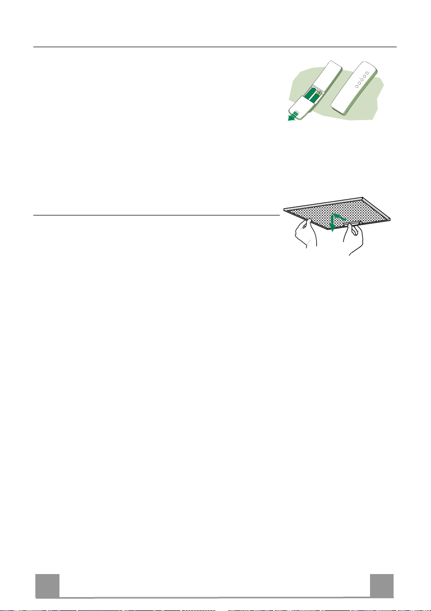
REMOTE CONTROL (OPTIONAL)
The appliance can be controlled using a remote control powered
by a 1.5 V carbon-zinc alkaline batteries of the standard LR03AAA type (not included).
• Do not place the remote control near to heat sources.
• Used batteries must be disposed of in the proper manner.
Metal grease filters
Metal filters can be washed also in a dish machine. They need to
be washed every time a FF-symbol appears in the display or at
least every two months. In case of very frequent use these have to
be washed even more often.
Alarm reset
• Switch off the lights and the motor. If the 24h mode is activated it is necessary to switch it off.
• Press the E-key until the display is unlit.
Cleaning
• Open the comfort panel pulling them slightly.
• Remove the filters one by one by pushing them backwards and
pulling them down contemporaneously.
• Wash the filters. Pay attention not to bend them. Make sure
that filters are completely dry before putting them into their
seat. (a possible modification of the filter surface doesn’t influence its efficiency).
• Place the filters again into their seats and make sure that the
handle of the filter remains outside.
• Close the comfort panel.
EN
1
10
Page 11

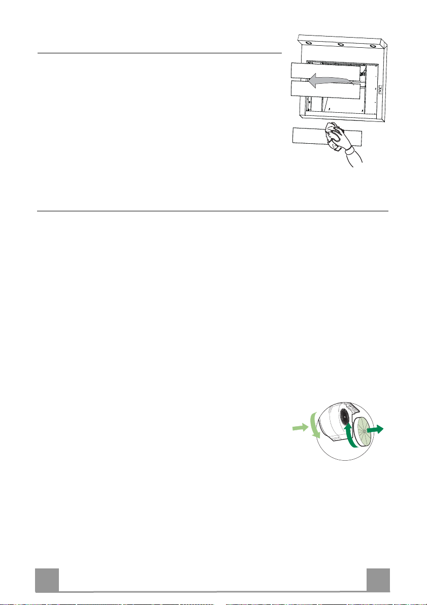
Comfort panels
A
B
• Remove the comfort panels pulling them slightly.
• It is recommended to use a neutral detergent liquid and a damp
cloth when washing the outer surface of the comfort panel.
• Wash the inner part of the panel as well by using a neutral detergent liquid and a damp cloth; in any case do not use wet
sponges or other clothes nor water jet or corrosive detergents.
• Let the get dry, and place them again in their correct position.
Charcoal filter (recycling version)
• This filter cannot be washed or regenerated. It must be replaced when the EF appears on the
display or at least once every 4 months.
Activation of the alarm signal
• In the recycling version hoods the filter saturation alarm must be activated during the installation or later.
• Switch off the hood and the lights.
• Disconnect the hood from the mains supply.
• When restoring the connection press and hold B-key.
• When releasing the key two rotating rectangles appear on the display.
• Within 3 seconds press the B-key until a flashing confirmation appears on the dispaly:
• 2 flashes with EF - charcoal filter saturation alarm ACTIVATED
• 1 flash with EF - charcoal filter saturation alarm DEACTIVATED.
REPLACING THE CHARCOAL FILTER
Reset of the alarm signal
• Switch off the hood and the lighting. If the 24h-function has
been activated this has to be deactivated.
• Press the E-key until the display is unlit.
Replacing of the filter
• Remove the comfort panels pulling them slightly.
• Remove the grease filters.
• Remove the saturated charcoal filter as indicated (A).
• Place the new filetrs as indicated (B).
• Put the metal grease filters into their seats.
• Place the comfort panels into their seats again.
EN
1
11
Page 12

Lighting system
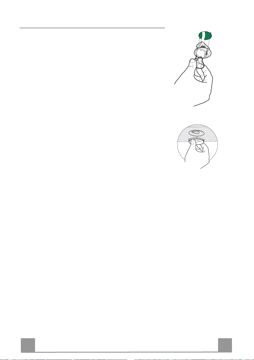
REPLACING OF THE LAMPS
20 W halogen lamps
• Loose the 2 fixing screws of the lighting support and remove
the support from the hood.
• Take off the lamp from the support.
• Replace the lamp with a new one. Make sure that the pins are
correctly seated in the support.
• Place the support again in its place. Fix it with the screws
which were earlier removed.
The 90 cm hood version is equipped with halogen lamps (20W)
placed in the upper part of the hood.
When replacing the lamps proceed as follows:
• Remove the metallic glass holder by levering it from under the
metal ring, supporting it with one hand.
• Remove the halogen lamp from the lamp holder.
• Replace the lamp with a new one. Make sure that the pins are
correctly seated in the support.
• Place the glass holder again in its place.
EN
1
12
Page 13

CONSIGLI E SUGGERIMENTI
Questo libretto di istruzioni per l'uso è previsto per più versioni dell' apparecchio.
É possibile che siano descritti singoli particolari della dotazione, che non riguardano il Vostro apparecchio.
INSTALLAZIONE
• Il produttore declina qualsiasi responsabilità per danni dovuti ad installazione non
corretta o non conforme alle regole dell’arte.
• La distanza minima di sicurezza tra il Piano di cottura e la Cappa deve essere di
650 mm, (alcuni modelli possono essere installati ad un’altezza inferiore, fare riferimento ai paragrafi ingombro e installazione).
• Verificare che la tensione di rete corrisponda a quella riportata nella targhetta
posta all’interno della Cappa.
• Per Apparecchi in Classe I
sca un corretto scarico a terra.
• Collegare la Cappa all’uscita dell’aria aspirata con tubazione di diametro pari o
superiore a 120 mm. Il percorso della tubazione deve essere il più breve possibile.
• Non collegare la Cappa a condotti di scarico dei fumi prodotti da combustione
(caldaie, caminetti, ecc.).
• Nel caso in cui nella stanza vengano utilizzati sia la Cappa che apparecchi non
azionati da energia elettrica (ad esempio apparecchi utilizzatori di gas), si deve
provvedere ad una aerazione sufficiente dell’ambiente. Se la cucina ne fosse
sprovvista, praticare un’apertura che comunichi con l’esterno, per garantire il richiamo d’aria pulita.
USO
• La Cappa è stata progettata esclusivamente per uso domestico, per abbattere gli
odori della cucina.
• Non fare mai uso improprio della Cappa.
• Non lasciare fiamme libere a forte intensità sotto la Cappa in funzione.
• Regolare sempre le fiamme in modo da evitare una evidente fuoriuscita laterale
delle stesse rispetto al fondo delle pentole.
• Controllare le friggitrici durante l’uso: l’olio surriscaldato potrebbe infiammarsi.
• Non preparare alimenti flambè sotto la cappa da cucina; pericolo d'incendio.
• Questo apparecchio non deve essere utilizzato da persone (bambini inclusi) con
ridotte capacità psichiche, sensoriali o mentali, oppure da persone senza esperienza e conoscenza, a meno che non siano controllati o istruiti all’uso
dell’apparecchio da persone responsabili della loro sicurezza.
• I bambini devono essere supervisionati per assicurarsi che non giochino con
l’apparecchio.
MANUTENZIONE
• Prima di procedere a qualsiasi operazione di manutenzione, disinserire la Cappa
togliendo la spina elettrica o spegnendo l’interruttore generale.
• Effettuare una scrupolosa e tempestiva manutenzione dei Filtri secondo gli intervalli consigliati (Rischio di incendio).
• Per la pulizia delle superfici della Cappa è sufficiente utilizzare un panno umido e
detersivo liquido neutro.
a
accertarsi che l’impianto elettrico domestico garanti-
Il simbolo sul prodotto o sulla confezione indica che il prodotto non deve essere considerato
come un normale rifiuto domestico, ma deve essere portato nel punto di raccolta appropriato per
il riciclaggio di apparecchiature elettriche ed elettroniche. Provvedendo a smaltire questo prodotto in modo appropriato, si contribuisce a evitare potenziali conseguenze negative per l’ambiente
e per la salute, che potrebbero derivare da uno smaltimento inadeguato del prodotto. Per informazioni più dettagliate sul riciclaggio di questo prodotto, contattare l’ufficio comunale, il servizio
locale di smaltimento rifiuti o il negozio in cui è stato acquistato il prodotto.
IT
1
13
Page 14
CARATTERISTICHE
Ingombro
Min.1305 - Max.1670
598 / 898
Componenti
Rif. Q.tà Componenti di Prodotto
1 1 Corpo Cappa completo di: Comandi, Luce, Gruppo
2.1 1 Camino Superiore
2.2 1 Camino Inferiore
8 1 Griglia direzionata Uscita Aria
9 1 Flangia riduzione 150-120
14.1 2 Prolunga Raccordo Uscita Aria
15 1 Raccordo Uscita Aria
16 1 Coperchio filtrante
Rif. Q.tà Componenti di Installazione
7.2.1 2 Staffe Fissaggio Camino Superiore
7.3 1 Staffa Sostegno Raccordo
11 6 Tasselli
11a 2 Tasselli SB 12/10
12a 6 Viti 4,2 x 44,4
12c 10 Viti 2,9 x 6,5
12d 2 Viti 2,9 x 9,5
Q.tà Documentazione
1 Libretto Istruzioni
Ventilatore, Filtri
126
81
12a
7.2.1 11
2.1
2.2
9
16
12c
15
14.1
7.3
12d
8
12c
11a
1
11
12a
IT
1
14
Page 15
INSTALLAZIONE
Foratura Parete e Fissaggio Staffe
7.2.1
7.3
11a
190 190
11
190
12a
11
362
190
22
Tracciare sulla Parete:
• una linea Verticale fino al soffitto o al limite superiore, al centro della zona prevista per il montaggio
della Cappa;
• una linea Orizzontale a 835 mm min. sopra il Piano di Cottura.
• Segnare un punto (1) sulla linea orizzontale a 190 mm alla destra della linea verticale di riferimento.
• Ripetere questa operazione dalla parte opposta, verificandone il livellamento.
• Segnare come indicato, un punto di riferimento (2) a 190 mm dalla linea Verticale di riferimento, e 362
mm sopra il Piano di Cottura.
• Ripetere questa operazione dalla parte opposta, verificandone il livellamento.
• Forare ø 12 mm i punti (1) segnati.
• Forare ø 8 mm i punti (2) segnati.
• Inserire i tasselli con staffa 11a nei fori 1 e avvitare.
• Inserire il tassello 11 nel foro 2.
Per installazione con camino decorativo: (Opzionale)
• Appoggiare come indicato la Staffa 7.2.1 a 1-2 mm dal soffitto o dal limite superiore, allineando il suo
centro (intagli) sulla linea Verticale di riferimento.
• Segnare i centri dei Fori della Staffa.
• Appoggiare come indicato la Staffa 7.2.1 a X mm sotto la prima staffa (X = altezza Camino Superiore
in dotazione), allineando il suo centro (intagli) sulla linea Verticale di riferimento.
• Segnare i centri dei Fori della Staffa.
• Forare ø 8 mm i punti segnati.
• Inserire i tasselli 11 nei fori.
• Fissare la Staffa inferiore 7.2.1 utilizzando le Viti 12a (4,2 x 44,4 ) in dotazione.
• Fissare insieme la Staffa superiore 7.2.1 e la Staffa sostegno raccordo 7.3 utilizzando le 2 viti 12a (4,2 x
44,4) in dotazione.
min. 250
max. 380
1÷2
X
Le quote di foratura
sono riferite alla di-
835
stanza minima di sicurezza di 250 mm
IT
1
15
Page 16

Montaggio Corpo Cappa
• Staccare i pannelli aspiranti tirandoli.
• Togliere i Filtri Antigrasso agendo sulle apposite
maniglie.
• Regolare le due viti Vr, delle staffe 11a, ad inizio
corsa.
• Agganciare il corpo cappa alle 2 staffe 11a.
• Dall’interno del corpo cappa agire sulle Viti Vr per
livellare il Corpo Cappa.
• Avvitare le viti di sicurezza 11.
Connessioni
USCITA ARIA VERSIONE ASPIRANTE
Per installazione in Versione Aspirante collegare la
Cappa alla tubazione di uscita per mezzo di un tubo
rigido o flessibile di ø150 o 120 mm, la cui scelta è lasciata all'installatore.
• Per collegamento con tubo ø120 mm, inserire la
Flangia di riduzione 9 sull’Uscita del Corpo Cappa.
• Fissare il tubo con adeguate fascette stringitubo. Il
materiale occorrente non è in dotazione.
• Togliere eventuali Filtri Antiodore al Carbone attivo.
ø 150
Vr
ø 120
9
Uscita aria Versione Filtrante
Per installazione in Versione Filtrante è necessario acquistare il kit opzionale Cartuccia al carbone attivo.
• Rimuovere l’angolare di fissaggio camino
• Avvitare il coperchio filtrante sull’uscita aria, utilizzando quattro viti 12c (2,9 x 6,5).
• Fissare la Griglia direzionata 8 sull’uscita dell’aria
riciclata con 2 Viti 12d (2,9 x 9,5) in dotazione.
IT
8
16
12d
12c
1
16
Page 17

USCITA ARIA VERSIONE FILTRANTE
15
ø 150
14.1
7.3
2.1
2.2
2
7.2.1
12c
12c
2.1
2.2
• Inserire lateralmente le Prolunghe Raccordo 14.1 sul Raccordo
15.
• Inserire il Raccordo 15 nella Staffa di Sostegno 7.3 fissandolo
con una Vite.
• Assicurarsi che l’uscita delle Prolunghe Raccordo 14.1 risulti
in corrispondenza delle bocchette del Camino sia in orizzontale
che in verticale.
• Collegare il Raccordo 15 all’Uscita del Corpo Cappa per mez-
zo di un tubo rigido o flessibile di ø150 mm, la cui scelta è lasciata all'installatore.
• Assicurarsi della presenza del Filtro Antiodore al Carbone attivo.
Montaggio Camino
Camino superiore
• Allargare leggermente le due falde laterali, agganciarle dietro
le Staffe 7.2.1 e richiuderle fino a battuta.
• Fissare lateralmente alle Staffe con 4 Viti 12c (2,9 x 9,5) in
dotazione.
Camino inferiore
• Allargare leggermente le due falde laterali del Camino, agganciarle tra il Camino superiore e la parete e richiuderle fino a
battuta.
• Fissare lateralmente la parte inferiore al Corpo Cappa, con 2
Viti 12c (2,9 x 9,5) in dotazione.
CONNESSIONE ELETTRICA
• Collegare la Cappa all’Alimentazione di Rete interponendo un
Interruttore bipolare con apertura dei contatti di almeno 3 mm.
• Rimuovere i Filtri antigrasso (vedi par. “Manutenzione”) e assicurarsi che il connettore del Cavo di alimentazione sia correttamente inserito nella presa dell’Aspiratore
IT
1
17
Page 18
USO
A
B
D
C
E
GH
F
Quadro comandi
Tasto Funzione Display
A Accende e spegne il motore di aspirazione all’ultima velo-
Visualizza la velocità impostata
cità utilizzata.
B Decrementa la velocità di esercizio.
C Incrementa la velocità di esercizio.
D Attiva la velocità intensiva da qualsiasi velocità anche da
motore spento, tale velocità è temporizzata a 10 minuti, al
Visualizza HI e il punto in basso a destra lam-
peggia una volta al secondo.
termine del tempo il sistema ritorna alla velocità precedentemente impostata. Adatta a fronteggiare le massime
emissioni di fumi di cottura.
E Attiva il motore ad una velocità che consente
un’aspirazione di 100 m
3
/h per 10 minuti ogni ora,
terminati il motore si ferma.
Con l’allarme filtri in corso premendo il tasto per circa 3
secondi si effettua il reset dell’allarme. Tali segnalazioni
sono visibili solo a motore spento.
Visualizza 24 e il punto in basso a destra lam-
peggia, mentre il motore è in funzione
Terminata la procedura si spegne la segnala-
zione precedentemente visualizzata:
FF segnala la necessità di lavare i filtri
EF segnala la necessità di sostituire i filtri al
F Attiva lo spegnimento automatico ritardato di 30’. Adatto
per completare l’eliminazione di odori residui. Attivabile da
qualsiasi posizione, si disattiva premendo il tasto o spegnendo il motore.
G Accende e spegne l’impianto di illuminazione.
Visualizza alternativamente la velocità di e-
sercizio e il tempo rimanente allo spegnimento
della cappa. Il punto in basso a destra lam-
peggia.
Solo nella cappa in versione da 90 cm se premuto per
circa 2 secondi accende l’illuminazione superiore
H Accende e spegne l’impianto di illuminazione ad intensità
ridotta.
antigrasso metallici. L’allarme entra in
funzione dopo 100 ore di lavoro effettivo della Cappa.
carbone attivo e devono anche essere
lavati i filtri antigrasso metallici. L’allarme entra in funzione dopo 200 ore di
lavoro effettivo della Cappa.
IT
1
18
Page 19
MANUTENZIONE
TELECOMANDO (OPZIONALE)
Questo apparecchio può essere comandato per mezzo di un telecomando, alimentato con pile alcaline zinco-carbone da 1,5 V del
tipo standard LR03-AAA (non incluse).
• Non riporre il telecomando in prossimità di fonti di calore.
• Non disperdere le pile nell’ambiente, depositarle negli appositi
contenitori.
Filtri antigrasso metallici
Sono lavabili anche in lavastoviglie, e necessitano di essere lavati
quando sul display appare FF o almeno ogni 2 mesi circa di utilizzo o più frequentemente, per un uso particolarmente intenso.
Reset del segnale di allarme
• Spegnere le Luci e il Motore di aspirazione, quindi qualora
fosse attivata la funzione 24h disattivarla.
• Premere il tasto E sino allo spegnersi del display.
Pulizia Filtri
• Togliere i Comfort Panel tirandoli.
• Togliere i Filtri uno alla volta, spingendoli verso la parte posteriore del gruppo e tirando contemporaneamente verso il basso.
• Lavare i Filtri evitando di piegarli, e lasciarli asciugare prima
di rimontarli. (Un’eventuale cambiamento del colore della superficie del filtro, che potrebbe verificarsi nel tempo, non pregiudica assolutamente l’efficienza dello stesso.)
• Rimontarli facendo attenzione a mantenere la maniglia verso la
parte visibile esterna.
• Riposizionare i comfort panel.
IT
1
19
Page 20
Pannelli Aspiranti
A
B
• Togliere i pannelli aspiranti tirandoli.
• Pulire esternamente con un panno umido e detersivo liquido
neutro.
• Pulirlo anche internamente utilizzando un panno umido e detergente neutro; non utilizzare panni o spugne bagnate, né getti
d’acqua; non utilizzare sostanze abrasive.
• Lasciarli asciugare e riposizionali nell’apposita sede.
Filtri antiodore al Carbone attivo (Versione Filtrante)
• Non è lavabile e non è rigenerabile, va sostituito quando sul display appare EF o almeno
ogni 4 mesi.
Attivazione del segnale di allarme
• Nelle Cappe in Versione Filtrante, la segnalazione di Allarme saturazione Filtri va attivata al
momento dell’installazione o successivamente.
• Spegnere le Luci e il Motore di aspirazione.
• Scollegare la cappa dall’alimentazione di rete.
• Ripristinare il collegamento tenendo premuto il tasto B.
• Rilasciando il tasto sul display compaiono due rettangoli in rotazione.
• Entro 3 secondi premere il Tasto B sino alla conferma che appare sul display:
• 2 lampeggi scritta EF - Allarme saturazione Filtro Carbone attivo ATTIVATO
• 1 lampeggio scritta EF - Allarme saturazione Filtro al Carbone attivo DISATTIVATO.
SOSTITUZIONE FILTRO ANTIODORE AL CARBONE ATTIVO
Reset del segnale di allarme
• Spegnere le Luci e il Motore di aspirazione, quindi qualora
fosse attivata la funzione 24h disattivarla.
• Premere il tasto E sino allo spegnersi del display.
Sostituzione Filtro
• Togliere i Comfort Panel tirandoli.
• Togliere i Filtri antigrasso metallici.
• Rimuovere i Filtri antiodore al Carbone attivo saturi, come indicato (A).
• Montare i nuovi Filtri, come indicato (B).
• Rimontare i Filtri antigrasso metallici.
• Riposizionare i Comfort Panel.
IT
2
20
Page 21
Illuminazione
SOSTITUZIONE LAMPADE
Lampade alogene da 20 W.
• Togliere le due viti che fissano il Supporto illuminazione e sfilarlo dalla Cappa.
• Estrarre la Lampada dal Supporto.
• Sostituirla con una nuova di uguali caratteristiche, facendo attenzione di inserire correttamente i due spinotti nella sede del
Supporto.
• Rimontare il Supporto fissandola con le due Viti precedentemente tolte.
Solo nella versione da 90 cm sono presenti delle Lampade alogene
(20W) posizionate nella parte superiore della cappa.
Per la sostituzione procedere come segue:
• Togliere il bloccavetro metallico a pressione facendo leva sotto
la ghiera, sostenendolo con una mano.
• Estrarre la lampadina alogena dal portalampada.
• Sostituirla con una nuova lampadina di uguali caratteristiche,
facendo attenzione ad inserire correttamente i due spinotti nella
sede del portalampade.
• Rimontare il bloccavetro a pressione.
IT
2
21
Page 22

CONSEILS ET SUGGESTIONS
La présente notice d'emploi vaut pour plusieurs versions de l'appareil. Elle peut conte-
nir des descriptions d'accessoires ne figurant pas dans votre appareil.
INSTALLATION
• Le fabricant décline toute responsabilité en cas de dommage dû à une installation non
correcte ou non conforme aux règles de l’art.
• La distance minimale de sécurité entre le plan de cuisson et la hotte doit être de 650
mm au moins (certains modèles peuvent être installés à une hauteur inférieure : se reporter aux paragraphes « Encombrement » et « Installation »).
• Vérifier que la tension du secteur correspond à la valeur qui figure sur la plaquette
apposée à l’intérieur de la hotte.
• Pour les Appareils appartenant à la Ière Classe, veiller à ce que la mise à la terre de
l’installation électrique domestique ait été effectuée conformément aux normes en vigueur.
• Connecter la hotte à la sortie d’air aspiré à l’aide d’une tuyauterie d’un diamètre égal ou
supérieur à 120 mm. Le parcours de la tuyauterie doit être le plus court possible.
• Ne pas connecter la hotte à des conduites d’évacuation de fumées issues d’une combustion tel que (Chaudière, cheminée, etc…).
• Si vous utilisez des appareils qui ne fonctionnent pas à l’électricité dans la pièce ou est
installée la hotte (par exemple: des appareils fonctionnant au gaz), vous devez prévoir
une aération suffisante du milieu. Si la cuisine en est dépourvue, pratiquez une ouverture qui communique avec l’extérieur pour garantir l’infiltration de l’air pur.
UTILISATION
• La hotte a été conçue exclusivement pour l’usage domestique, dans le but d’éliminer
les odeurs de la cuisine.
• Ne jamais utiliser abusivement la hotte.
• Ne pas laisser les flammes libres à forte intensité quand la hotte est en service.
• Toujours régler les flammes de manière à éviter toute sortie latérale de ces dernières
par rapport au fond des marmites.
• Contrôler les friteuses lors de l’utilisation car l’huile surchauffée pourrait s’enflammer.
• Ne pas préparer d’aliments flambés sous la hotte de cuisine : risque d’incendie
• Cet appareil ne doit pas être utilisé par des personnes (y compris les enfants) ayant
des capacités psychiques, sensorielles ou mentales réduites, ni par des personnes
n’ayant pas l’expérience et la connaissance de ce type d’appareils, à moins d'être sous
le contrôle et la formation de personnes responsables de leur sécurité.
• Les enfants doivent être surveillés pour s'assurer qu'ils ne jouent pas avec l'appareil.
ENTRETIEN
• Avant de procéder à toute opération d’entretien, retirer la hotte en retirant la fiche ou en
actionnant l’interrupteur général.
• Effectuer un entretien scrupuleux et en temps dû des Filtres, à la cadence conseillée
(Risque d’incendie).
• Pour le nettoyage des surfaces de la hotte, il suffit d’utiliser un chiffon humide et détersif liquide neutre.
Le symbole sur le produit ou son emballage indique que ce produit ne peut être traité comme
déchet ménager. Il doit plutôt être remis au point de ramassage concerné, se chargeant du recyclage du matériel électrique et électronique. En vous assurant que ce produit est éliminé correctement, vous favorisez la prévention des conséquences négatives pour l’environnement et la santé
humaine qui, sinon, seraient le résultat d’un traitement inapproprié des déchets de ce produit. Pour
obtenir plus de détails sur le recyclage de ce produit, veuillez prendre contact avec le bureau municipal de votre région, votre service d’élimination des déchets ménagers ou le magasin où vous avez
acheté le produit.
FR
2
22
Page 23

CARACTERISTIQUES
Encombrement
Min.1305 - Max.1670
598 / 898
Composants
Réf. Q.té Composants de Produit
1 1 Corps Hotte équipé de:Comandes, Lumière, Groupe
2.1 1 Cheminée Supérieure
2.2 1 Cheminée Inférieure
8 1 Grille orientée Sortie de l’Air
9 1 Flasque
14.1 2 Rallonge Raccord Sortie Air
15 1 Raccord Sortie Air
16 1 Couvercle filtrant
Réf. Q.té Composants pour l ’installation
7.2.1 2 Brides Fixation Cheminée Supérieure
7.3 1 Bride Support Raccord
11 6 Chevilles
11a 2 Chevilles SB 12/10
12a 6 Vis 4,2 x 44,4
12c 10 is 2,9 x 6,5
12d 2 Vis 2,9 x 9,5
Q.té Documentation
1 Manuel d’instructions
Ventilateur, Filtres
126
81
12a
7.2.1 11
2.1
2.2
9
16
12c
15
14.1
7.3
12d
8
12c
11a
1
11
12a
FR
2
23
Page 24

INSTALLATION
Perçage Paroi et Fixation Brides
1÷2
7.2.1
7.3
X
11a
12a
11
190 190
11
190
22
362
Les indications de per-
190
835
çage se réfèrent à la distance minimale de sécurité de 250 mm.
min. 250
max. 380
Tracer sur la Paroi :
• une ligne Verticale jusqu’au plafond ou à la limite supérieure, au centre de la zone prévue
pour le montage de la Hotte ;
• une ligne Horizontale à 835 mm. min. au-dessus des Plaques de Cuisson.
• Marquer un point (1) sur la ligne horizontale à 190 mm. à droite de la ligne verticale de référence.
• Répéter cette opération du côté opposé, en vérifiant le nivellement.
• Marquer comme indiqué, un point de référence (2) à 190 mm de la ligne verticale de repère,
et 362 mm au-dessus des Plaques de Cuisson.
• Répéter cette opération du côté opposé, en vérifiant le nivellement.
• Percer des trous de ø 12 mm. en correspondance des points (1) marqués.
• Percer des trous de ø 8 mm. en correspondance des points (2) marqués.
• Insérer les chevilles avec bride 11a dans les trous 1 puis visser.
• Insérer la cheville 11 dans le trou 2.
Pour l’installation avec cheminée décorative ( si fournies )
• Poser comme indiqué une bride 7.2.1 sur la paroi à 1-2 mm du plafond ou de la limite supérieure, en alignant son centre (découpes) sur la ligne verticale de repère.
• Marquer les centres des trous rainurés de la bride.
• Poser comme indiqué la bride 7.2.1 à X mm sous la première bride (X = hauteur cheminée
supérieure fournie), en alignant son centre (découpes) sur la ligne verticale de repère.
• Marquer les centres des trous rainurés de la bride.
• Percer de ø 8 mm tous les points marqués.
• Insérer les chevilles 11 dans les trous.
• Fixer la bride inférieure 7.2.1 en utilisant les vis 12a (4,2 x 44,4) fournies.
• Fixer ensemble la bride supérieure 7.2.1 et le support 7.3 en utilisant les vis 12a (4,2 x 44,4)
fournies.
FR
2
24
Page 25

Montage du corps de la hotte
• Tirer sur les panneaux aspirants pour les ôter.
• Retirer les filtres à graisse au moyen des poignées
prévues à cet effet.
• Placer les deux vis Vr, sur les équerres 11a sans les
visser (B).
• Accrocher le corps de la hotte aux 2 équerres 11a.
• Mettre à niveau le corps de la hotte de l’intérieur en
agissant sur les vis Vr.
• Visser les vis de sécurité 11.
Branchements
SORTIE AIR VERSION ASPIRANTE
En cas d’installation en version aspirante, brancher la
hotte à la tuyauterie de sortie via un tube rigide ou
flexible de ø 150 ou 120 mm, au choix de l’installateur.
• En cas de branchement avec un tube de ø120 mm,
insérer le flasque de réduction 9 sur la sortie du corps
de la hotte.
• Fixer le tube par des colliers appropriés. Le matériau
nécessaire n’est pas fourni.
• Retirer les éventuels filtres anti-odeur au charbon
actif.
ø 150
Vr
ø 120
9
SORTIE AIR VERSION FILTRANTE
Pour l’installation dans la Version Filtrante, il faut
acheter le kit fourni sur demande Cartouche au charbon
actif.
• Enlever la cornière de la cheminée
• Visser le couvercle filtrant sur la sortie de l’air, en
utilisant les quatre vis 12c (2,9 x 6,5).
• Fixer la Grille orientée 8 sur la sortie de l’air recyclé
à l’aide de 2 Vis 12d (2,9 x 9,5) fournies avec
l’appareil.
FR
8
16
12d
12c
2
25
Page 26

SORTIE AIR VERSION FILTRANTE
15
ø 150
14.1
7.3
2.1
2.2
2
7.2.1
12c
12c
2.1
2.2
• Insérer latéralement les rallonges raccord 14.1 sur le raccord
15.
• Placer le raccord 15 dans l’étrier de soutien 7.3 en le fixant
avec une vis.
• S’assurer que la sortie des rallonges raccord 14.1 se trouve au
niveau des bouches de la cheminée aussi bien en horizontal
qu’en vertical.
• Brancher le raccord 15 à la sortie du corps de la hotte avec un
tube rigide ou flexible de ø 150 mm, selon le choix de
l’installateur.
• S’assurer de la présence des filtres anti-odeur au charbon actif.
Montage Cheminée
Cheminée supérieure
• Elargir légèrement les deux bords latériaux, et les accrocher
derrières les brides 7.2.1; refermer jusqu’à la butée.
• Fixer latéralement aux brides à l’aide des 4 vis 12c fournies.
Cheminée inférieure
• Elargir légèrement les deux bords latériaux de la Cheminée et
les accrocher entre la Cheminée supérieure et la paroi; refermer
jusqu’à la butée.
• Fixer latéralement la partie inférieure au corps hotte, à l’aide
des deux 2 vis 12c fournies.
BRANCHEMENT ELECTRIQUE
• Brancher la hotte sur le secteur en interposant un interrupteur
bipolaire avec ouverture des contacts d’au moins 3 mm.
• Enlever les filtres à graisse (voir § "Entretien") et s'assurer que
le connecteur du câble d'alimentation soit bien branché dans la
prise du diffuseur.
FR
2
26
Page 27

UTILISATION
A
B
D
C
E
GH
F
Tableau des commandes
Touche Fonction Afficheur
A
Allume et éteint le moteur d’aspiration à la dernière
vitesse utilisée
B Diminue la vitesse de service
C Augmente la vitesse de service
D
Active la vitesse intensive à partir de n’importe quelle
vitesse, même du moteur arrêté. Cette vitesse est
programmée pour durer 10 minutes, après quoi le
système retourne à la vitesse réglée au préalable.
Sert à faire face à une quantité maximale de fumées
de cuisson.
E
Active le moteur à une vitesse permettant une
aspiration de 100 m
3
/h pendant 10 minutes toutes les
heures, puis le moteur s’arrête.
Quand l’alarme filtres est déclenchée, appuyer sur
cette touche pendant 3 secondes environ pour
remettre l’alarme à l’état initial. Ces indications sont
visibles uniquement quand le moteur est éteint.
F
Active l’arrêt automatique retardé de 30 minutes.
Utile pour achever d’éliminer toute odeur résiduelle.
S’active depuis toutes les positions et se désactive
en appuyant sur la touche ou en éteignant le moteur.
G Allume et éteint l’éclairage.
Uniquement pour la version de 90 cm, appuyer pendant environ 2 secondes pour allumer l’éclairage
supérieur.
H Allume et éteint l’éclairage à intensité réduite.
Affiche la vitesse choisie
Affiche HI et le point en bas à droite clignote une
fois par seconde.
Affiche 24 et le point en bas à droite clignote,
quand le moteur fonctionne.
En fin de procédure, le signal affiché
précédemment s’éteint :
FF indique qu’il faut laver les filtres à graisse
métalliques. L’alarme se déclenche après
100 heures de fonctionnement effectif de
la hotte.
EF indique qu’il faut remplacer les filtres au
charbon actif et laver les filtres à graisse
métalliques. L’alarme se déclenche après
200 heures de fonctionnement effectif de
la hotte.
Affiche tout à tour la vitesse de service et le
temps restant avant l’arrêt de la hotte. Le point
en bas à droite clignote.
FR
2
27
Page 28

ENTRETIEN
TELECOMMANDE (FOURNIE SUR DEMANDE)
Il est possible de commander cet appareil au moyen d’une télécommande, alimentée avec des piles alcalines zinc-charbon 1,5 V
du type standard LR03-AAA (non compris).
• Ne pas ranger la télécommande à proximité de sources de chaleur.
• Ne pas jeter les piles; il faut les déposer dans les récipients de
récolte spécialement prévus à cet effet.
Filtres à graisse métalliques
Ils sont lavables en lave-vaisselle et doivent être lavés chaque
fois que le symbole FF s’affiche ou environ tous les 2 mois ou
plus souvent même, en cas d’utilisation particulièrement intensive.
Acquittement du signal d’alarme
• Éteindre les lumières et le moteur d’aspiration; au cas où la
fonction 24h est active, il convient de la désactiver.
• Appuyer sur la touche E jusqu’à ce que l’afficheur s’éteigne.
Nettoyage des filtres
• Tirer sur les panneaux confort pour les ôter.
• Retirer les filtres, un à un, en les poussant vers l’arrière du
groupe tout en les tirant vers le bas.
• Laver les filtres en évitant de les plier, et les faire sécher avant
de les remonter. (Tout changement de couleur sur la surface du
filtre, susceptible de se produire avec le temps, ne nuit en rien à
l’efficacité de ce dernier.)
• Remonter les filtres en faisant attention de tenir la poignée vers
la partie externe visible.
• Replacer les panneaux confort.
FR
2
28
Page 29

Panneaux aspirants
A
B
• Tirer sur les panneaux aspirants pour les ôter.
• Nettoyer l’extérieur avec un chiffon humide imbibé de détergent liquide neutre.
• Nettoyer également l’intérieur à l’aide d’un chiffon humide
imbibé de détergent neutre ; ne pas utiliser de chiffons ou
d’éponges mouillés, ni de jet d’eau ; ne pas utiliser de produits
abrasifs.
• Laisser sécher et remettre correctement en position.
Filtre anti-odeur au charbon actif (version filtrante)
• Il ne peut être ni lavé ni récupéré, il faut le changer quand EF s’affiche ou au moins tous les
4 mois.
Déclenchement du signal d’alarme
• Pour les Hottes en Version Filtrante, l’alarme indiquant la saturation des Filtres doit être
activée au moment de l’installation ou ultérieurement.
• Éteindre les lumières et le moteur d’aspiration.
• Débrancher la hotte du réseau électrique.
• Rétablir le branchement en appuyant sur la touche B.
• Lâcher la touche et deux rectangles en rotation apparaissent sur l’afficheur.
• Dans les 3 secondes qui suivent, appuyer sur la touche B jusqu’à ce que s’affichent :
• EF clignotant deux fois – Alarme saturation filtre charbon active VALIDEE.
• EF clignotant un fois – Alarme saturation filtre charbon active INVALIDEE.
REMPLACEMENT DU FILTRE ANTI-ODEUR AU CHARBON ACTIF
Acquittement du signal d’alarme
• Éteindre les lumières et le moteur d’aspiration; au cas où la
fonction 24h est active, il convient de la désactiver.
• Appuyer sur la touche E jusqu’à ce que l’afficheur s’éteigne.
Remplacement du Filtre
• Tirer sur les panneaux confort pour les ôter.
• Retirer les Filtres à graisse métalliques.
• Retirer les filtres anti-odeur au charbon actif saturés, selon les
indications (A).
• Placer les nouveaux filtres, selon les indications (B).
• Remonter les Filtres à graisse métalliques.
• Replacer les panneaux confort.
FR
2
29
Page 30

Éclairage
REMPLACEMENT DES LAMPES
Lampes halogènes de 20 W.
• Retirer les deux vis fixant le support de l’éclairage et le retirer
de la hotte.
• Extraire la lampe du support.
• La remplacer par une nouvelle lampe ayant les mêmes caractéristiques. Faire attention de placer correctement les deux broches dans le logement du support.
• Remonter le support en le fixant à l’aide des deux vis retirées
au préalable.
Seule la version de 90 cm dispose de lampes halogènes (20W) situées dans la partie supérieure de la hotte.
Pour remplacer les lampes, procéder comme suit :
• Retirer le joint de blocage du verre en faisant levier sous la bague et en tenant le verre pour éviter qu’il ne tombe.
• Extraire la lampe halogène du porte-ampoule.
• La remplacer par une nouvelle lampe ayant les mêmes caractéristiques. Faire attention de placer correctement les deux broches dans le logement du porte-ampoule.
• Remonter le joint de blocage du verre qui se place par encliquetage.
FR
3
30
Page 31

EMPFEHLUNGEN UND HINWEISE
Diese Gebrauchsanleitung gilt für mehrere Geräte-Ausführungen. Es ist möglich, dass
einzelne Ausstattungsmerkmale beschrieben sind, die nicht auf Ihr Gerät zutreffen.
MONTAGE
• Der Hersteller haftet nicht für Schäden, die auf eine fehlerhafte und unsachgemäße Montage zurückzuführen sind.
• Der minimale Sicherheitsabstand zwischen Kochmulde und Haube muss 650 mm betragen (einige Modelle können an einer geringeren Höhe installiert werden, beziehen Sie sich
dazu auf den Absatz Raumbedarf und Installation).
• Prüfen, ob die Netzspannung mit dem Wert auf dem im Haubeninneren angebrachten Schild übereinstimmt.
• Bei Geräten der Klasse I ist sicherzustellen, dass die elektrische Anlage des Wohnhauses
über eine vorschriftsmäßige Erdung verfügt.
• Das Anschlussrohr der Haube zur Luftaustrittsöffnung muss einen Durchmesser von 120
mm oder darüber aufweisen. Der Rohrverlauf muss so kurz wie möglich sein.
• Die Haube darf an keine Entlüftungsschächte angeschlossen werden, in die Verbrennungsgase (Heizkessel, Kamine usw.) geleitet werden.
• Werden im Raum außer der Dunstabzugshaube andere, nicht elektrisch betriebene (z.B.
gasbetriebene) Geräte verwendet, muss für eine ausreichende Belüftung gesorgt werden.
Sollte die Küche diesbezüglich nicht entsprechen, ist an einer Aussenwand eine Öffnung
anzubringen, die Frischluftzufuhr gewährleistet.
BEDIENUNG
• Die Dunstabzugshaube ist ausschließlich zum Einsatz im privaten Haushalt und zur
Beseitigung von Küchengerüchen vorgesehen.
• Unsachgemäßer Einsatz der Haube ist zu unterlassen.
• Große Flammen bei eingeschalteter Haube niemals unbedeckt lassen.
Achtung! Große Flammen bei eingeschalteter Haube niemals unbedeckt lassen.
• Die Intensivität der Flamme ist so zu regulieren, dass sie den Topfboden nicht überragt.
Achtung! Frittiergeräte müssen während des Gebrauchs stets beaufsichtigt wer-
den: Überhitztes Öl kann sich entzünden.
• Frittiergeräte müssen während des Gebrauchs stets beaufsichtigt werden: überhitztes Öl
kann sich entzünden.
• Keine flambierten Speisen unter der Abzugshaube zubereiten: Brandgefahr.
• Dieses Gerät darf nicht von Personen, auch Kindern, mit verminderten psychischen, sensorischen und geistigern Fähigkeiten, oder von Personen ohne Erfahrung und Kenntnisse
benutzt werden, sofern sie nicht von für ihre Sicherheit verantwortlichen Personen beaufsichtigt und beim Gebrauch des Geräts angeleitet werden.
• Kinder dürfen sich nicht unbeaufsichtigt in der Nähe des Geräts aufhalten und auf keinen
Fall mit dem Gerät spielen.
WARTUNG
• Bevor Wartungsarbeiten durchgeführt werden, muss die Stromzufuhr zur Haube unterbrochen werden, indem der Stecker gezogen oder der Hauptschalter abgeschaltet wird.
• Bei der Filterwartung müssen die vom Hersteller empfohlenen Zeiträume zum Austauschen
der Filter genauestens eingehalten werden (Brandgefahr).
• Zur Reinigung der Haubenflächen Wir empfehlen ein feuchtes Tuch und ein mildes Flüssigreinigungsmittel.
• Bitte keine Reinigungsmittel mit Scheuermittel verwenden. Die Oberfläche wird damit
verkratzt.
Das Symbol auf dem Produkt oder seiner Verpackung weist darauf hin, dass dieses Produkt nicht als
normaler Haushaltsabfall zu behandeln ist, sondern an einem Sammelpunkt für das Recycling von elektrischen und elektronischen Geräten abgegeben werden muss. Durch Ihren Beitrag zum korrekten Entsorgen
dieses Produkts schützen Sie die Umwelt und die Gesundheit Ihrer Mitmenschen. Umwelt und Gesundheit
werden durch falsches Entsorgen gefährdet. Weitere Informationen über das Recycling dieses Produkts
erhalten Sie von Ihrem Rathaus, Ihrer Müllabfuhr oder dem Geschäft, in dem Sie das Produkt gekauft haben.
DE
3
31
Page 32

CHARAKTERISTIKEN
Platzbedarf
Min.1305 - Max.1670
598 / 898
Komponenten
Pos. St. Produktkomponenten
1 1 Haubenkörper mit Schaltern, Beleuchtung, Gebläse-
2.1 1 oberer Kaminteil
2.2 1 unterer Kaminteil
8 1 Luftleitgitter Luftaustritt
9 1 Flansch
14.1 2 Verlängerung Luftaustritt-Anschlussstück
15 1 Luftaustritt-Anschlussstück
16 1 Filterdeckel
Pos. St. Montagekomponenten
7.2.1 2 Befestigungsbügel oberer Kaminteil
7.3 1 Bügel für Anschlusshalter
11 6 Dübel
11a 2 Dübel SB 12/10
12a 6 Schrauben 4,2 x 44,4
12c 10 Schrauben 2,9 x 6,5
12d 2 Schrauben 2,9 x 9,5
St. Dokumentation
1 Bedienungsanleitung
gruppe, Filter
126
81
12a
7.2.1 11
2.1
2.2
9
16
12c
15
14.1
7.3
12d
8
12c
11a
1
11
12a
DE
3
32
Page 33

MONTAGE
Bohren der Befestigungslöcher und Fixieren der Befestigungsbügel
7.2.1
7.3
11a
190 190
11
190
12a
11
190
22
362
Achtung: Bitte beachten Sie bei der Montage das Gewicht der kompletten Haube. Die Tragfähigkeit der Decke
oder alternativ der Trägerplatte für diese Zugbelastung muss vor der Montage geprüft und gegebenenfalls durch
die Anbringung von geeigneten Befestigungs- oder Stabilisierungselementen hergestellt werden. Kann eine hinreichende Tragfähigkeit nicht sichergestellt werden, ist von einer Montage abzusehen.
An der Wand:
• eine vertikale Linie bis zur Decke oder oberen Begrenzung zeichnen, und zwar in der Mitte des Bereiches, der zur Montage der Haube vorgesehen ist;
• eine horizontale Linie mindestens 835 mm oberhalb der Kochmulde zeichnen.
• 190 mm rechts von der vertikalen Bezugslinie einen Punkt(1)auf der horizontalen Linie kennzeichnen.
• Diesen Vorgang an der gegenüberliegenden Seite wiederholen und die Ausrichtung überprüfen.
• Wie beschrieben einen Bezugspunkt (2) 190 mm von der vertikalen Bezugslinie und 362 mm der
Kochmulde zeichnen.
• Diesen Vorgang an der gegenüberliegenden Seite wiederholen und die Ausrichtung überprüfen.
• Die gekennzeichneten Punkte (1) mit einem Bohrer ø 12 mm bohren.
• Die gekennzeichneten Punkte (2) mit einem Bohrer ø 8 mm bohren.
• Die Dübel mit dem Bügel 11a in die Bohrungen 1 einfügen und festschrauben.
• Den Dübel 11 in die Bohrung 2 einfügen.
Zur Montage der haube mit Dekorkamin (option)
• Einen Bügel 7.2.1 zirka 1-2 mm unter der Decke oder oberen Begrenzung an die Wand legen und seinen Mittelpunkt (Einschnitte) auf die vertikale Bezugslinie ausrichten.
• Die Mitte der beiden Bügellöcher an der Wand markieren.
• Den zweiten Bügel 7.2.1 an die Wand legen, wobei ein Abstand X mm vom oberen Bügel einzuhalten
ist (X = Höhe des jeweiligen oberen Kaminteils); den Mittelpunkt (Einschnitte) auf die vertikale Bezugslinie ausrichten.
• Die Mitte der Bügellöcher an der Wand markieren.
• Mit einem Bohrer ø 8 mm die markierten Punkte bohren.
• Die Dübel 11 in die Bohrungen einfügen.
• Den unteren Bügel mit den mitgelieferten Schrauben 12a (4,2 x 44,4) fixieren.
• Den Bügel für Anschlusshalter mit den 2 mitgelieferten Schrauben 12a (4,2 x 44,4) auf den oberen Bügel 7.2.1 befestigen.
min. 250
max. 380
1÷2
X
835
Die Bohrhöhen beziehen
sich auf den SicherheitsMindestabstand von 250
mm.
DE
3
33
Page 34

Montage des Haubenkörpers
• Die Absaugpaneele herausziehen.
• Die Fettfilter an den speziellen Griffen herausziehen.
• Die beiden Schrauben Vr der Bügel 11a auf den
Laufbeginn regulieren.
• Den Haubenkörper an den 2 Bügeln 11a einhaken.
• Vom Haubeninneren her den Haubenkörper mit Hilfe
der Schrauben Vr ausrichten.
• Die Sicherheitsschrauben 11 einschrauben.
Anschluss der Abluftversion
Bei Abluftbetrieb kann die Haube vom Installateur
wahlweise mittels Rohr oder Schlauch (ø 150 oder 120
mm) an die Außenrohrleitung angeschlossen werden.
• Bei Verwendung eines Anschlussrohres ø 120 den
Reduzierflansch 9 am Haubenaustritt anbringen.
• Das Rohr mit geeigneten Rohrschellen fixieren. Das
hierzu erforderliche Material wird nicht mitgeliefert.
• Eventuell vorhandene Aktivkohlefilter entnehmen.
Achtung! Alle Querschnittänderungen oder
Richtungsänderungen des Abluftkanals reduzieren
die Leistung der Haube.
ANSCHLUSS IN UMLUFTVERSION
Für die Installation in Umluftversion muss das optionale Kit „Aktivkohle-Filtereinsatz“ erworben werden.
• Das Winkelstück der Kaminbefestigung entfernen
• Den Filterdeckel am Luftausgang mit den vier
Schrauben 12c (2,9 x 6,5) fixieren.
• Das Luftleitgitter 8 mit Hilfe von 2 der mitgelieferten
Schrauben 12d (2,9 x 9,5) beim Austritt der rückzuführenden Luft fixieren.
Vr
ø 150
9
8
16
ø 120
12d
12c
DE
3
34
Page 35

Anschluss der Umluftversion
15
ø 150
14.1
7.3
2.1
2.2
2
7.2.1
12c
12c
2.1
2.2
• Die Verlängerungen 14.1 beim Anschluss 15 seitlich einfügen.
• Den Anschluss 15 am Haltebügel 7.3 einsetzen und mit einer
Schraube fixieren.
• Überprüfen, ob die Verlängerungen 14.1 mit den entsprechenden Kaminstutzen sowohl horizontal wie auch vertikal übereinstimmen.
• Vom Installateur wahlweise mittels Rohr oder Schlauch (ø 150
mm), den Anschluss 15 am Haubenaustritt anbringen.
• Kontrollieren, ob der Aktivkohle-Geruchsfilter montiert ist.
Kaminmontage
Oberer Kaminteil
• Die beiden seitlichen Schenkel leicht auseinanderbiegen, hinter
den Bügeln 7.2.1 einhängen und bis zum Anschlag wieder
schließen.
• Bei den Bügeln mit Hilfe der 4 mitgelieferten Schrauben 12c
fixieren.
Unterer Kaminteil
• Die beiden seitlichen Schenkel des Kaminteils leicht auseinanderbiegen, zwischen dem oberen Kaminteil und der Wand einhängen und bis zum Anschlag wieder schließen.
• Den unteren Teil seitlich am Haubenkörper mit 2 der mitgelieferten Schrauben 12c fixieren.
Elektroanschluss
Vor der Installation die Netzspannung durch herausdrehen der
Sicherung oder ausschalten des Hauptschalters stromlos machen.
• Bei Anschluss der Haube an das Stromnetz muss ein
zweipoliger Schalter mit einem Öffnungsweg von
mindestens 3 mm zwischengeschaltet werden.
• Entfernen Sie die Fettfilter (s. Abschnitt „Wartung“) und
versichern Sie sich, daß die Kabelverbindung in die Steckdose des Gebläses einwandfrei eingesteckt wird.
Achtung: Das Gerät nur an die Netzspannung die im Typen-
schild angegeben ist anschließen.
DE
3
35
Page 36

BEDIENUNG
A
B
D
C
E
GH
F
Bedienblende
Taste Funktion Display
Schaltet den Motor der Absauganlage bei der zu-
A
Zeigt die eingestellte Geschwindigkeit an
letzt verwendeten Geschwindigkeit ein und aus.
Vermindert die Betriebsgeschwindigkeit.
B
Erhöht die Betriebsgeschwindigkeit.
C
Aktiviert von jeder Geschwindigkeit aus, auch bei
D
abgestelltem Motor, die Intensivgeschwindigkeit, die
Zeigt HI an und der Punkt unten rechts blinkt ein-
mal pro Sekunde.
auf 10 Minuten zeitgeregelt ist. Nach Ablauf dieser
Zeit kehrt das System zu der zuvor eingestellten
Geschwindigkeit zurück. Für die Beseitigung von
sehr intensiven Kochdünsten geeignet.
Aktiviert den Motor bei einer Geschwindigkeit, die
E
eine Absaugleistung von 100 m
3
/h für die Dauer
von 10 Minuten jede Stunde ermöglicht, nach dessen Ablauf hält der Motor an.
Bei laufendem Filteralarm wird durch 3 Sekunden
anhaltendes Drücken der Taste ein Reset des A-
Zeigt 24 an und der Punkt unten rechts blinkt, während der Motor in Betrieb ist
Nach abgeschlossener Prozedur verlöscht die bisherige Anzeige:
FF zeigt an, dass der Metallfettfilter gewaschen
larms ausgelöst. Derlei Anzeigen sind nur bei abgestelltem Motor sichtbar.
EF zeigt an, dass die Aktivkohlefilter ausgewech-
Aktiviert das automatische Ausschalten mit einer
F
Verzögerung von 30 Min. Ermöglicht die Beseitigung von Restgerüchen und kann von jeder Position
Zeigt abwechselnd die Betriebsgeschwindigkeit und
die bis zum Abschalten der Abzugshaube verblei-
bende Zeit an. Der Punkt unten rechts blinkt.
aus aktiviert werden. Zum Deaktivieren die Taste
drücken oder den Motor abstellen.
Schaltet die Beleuchtung ein oder aus.
G
Nur bei 90 cm Haubenversionen wird durch zirka 2
Sekunden langes Drücken die obere Beleuchtung
eingeschaltet.
Schaltet die verminderte Beleuchtung ein oder aus.
H
werden muss. Dieser Alarm wird nach 100 effektiven Betriebsstunden der Abzugshaube
ausgelöst.
selt und die Metallfettfilter gewaschen werden
müssen. Dieser Alarm wird nach 200 effektiven Betriebsstunden der Abzugshaube ausgelöst.
DE
3
36
Page 37

WARTUNG
FERNBEDIENUNG (OPTION)
Dieses Gerät kann mit einer Fernbedienung gesteuert werden,
welche mit alkalischen Zink-Kohle-Batterien 1,5 V des Standardtyps LR03-AAA versorgt wird (nicht enthalten).
• Die Fernbedienung nicht in die Nähe von Hitzequellen legen.
• Batterien müssen vorschriftsmäßig entsorgt werden.
Metallfettfilter
Die Fettfilter sind spülmaschinengeeignet und müssen gewaschen
werden, sobald am Display die Aufschrift FF erscheint oder
mindestens alle 2 Monate, oder auch öfter, je nach Intensität des
Gebrauchs.
Reset des Alarmsignals
• Die Beleuchtung und den Absaugmotor abschalten und dann
die 24-Stunden-Funktion deaktivieren, falls diese zuvor aktiv
war.
• Die Taste E drücken, bis das Display verlöscht.
Reinigung der Filter
• Die Comfort Panels herausziehen.
• Die Filter einzeln ausbauen, indem sie in den hinteren Teil der
Gruppe geschoben und gleichzeitig nach unten gezogen werden.
• Die Filter waschen, ohne sie zu verbiegen, und vor dem erneuten Einbau trocknen lassen. (Die Farbe der Filteroberfläche
kann sich mit der Zeit verändern, was aber die Wirksamkeit
keinesfalls beeinträchtigt.)
• Nun die Filter wieder einbauen, so dass der Griff nach der äußeren Sichtseite zeigt.
• Die Comfort Panels wieder einbauen.
DE
3
37
Page 38

Absaugpaneele
A
B
• Die Absaugpaneele herausziehen.
• Die Außenflächen mit einem feuchten Lappen und einem neutralem Flüssigreiniger säubern.
• Auch Innen mit einem feuchten Lappen und einem neutralen
Reinigungsmittel säubern; keine nassen Tücher oder Schwämme, oder gar Wasser verwenden, und keine schleifenden Mittel
einsetzen.
• Trocknen lassen und wieder in ihren Sitz einbauen.
Aktivkohle-Geruchsfilter (Filterversion)
• Der Aktivkohlefilter ist weder waschbar, noch regenerierbar und muss ausgewechselt werden, wenn am Display die Aufschrift EF erscheint, oder nach mindestens 4 Monaten.
Aktivierung des Alarmsignals
• Bei den Filterversionen der Abzugshauben wird die Alarmanzeige für Filtersättigung im
Augenblick der Installation oder in der Folge aktiviert.
• Die Beleuchtung und den Abzugsmotor ausschalten.
• Die Abzugshaube von der Netzversorgung trennen.
• Den Anschluss wieder herstellen, indem die Taste B gedrückt wird.
• Bei Loslassen der Taste erscheinen am Display zwei drehende Rechtecke.
• Innerhalb von 3 Sekunden die Taste B drücken, bis am Display die Bestätigung erscheint:
• 2 maliges Blinken der Aufschrift EF – Sättigungsalarm Aktivkohlefilter AKTIVIERT
• 1 maliges Blinken der Aufschrift EF - Sättigungsalarm Aktivkohlefilter DEAKTIVIERT.
AUSWECHSELN DES AKTIVKOHLE-GERUCHSFILTERS
Reset des Alarmsignals
• Die Beleuchtung und den Absaugmotor abschalten und dann die 24Stunden-Funktion deaktivieren, falls diese zuvor aktiv war.
• Die Taste E drücken, bis das Display verlöscht.
Ersetzen des Filters
• Die Comfort Panels herausziehen.
• Die Fettfilter aus Metall entfernen.
• Die verbrauchten Aktivkohle-Geruchsfilter wie angegeben ausbauen
(A).
• Die neuen Filter wie angegeben einbauen (B).
• Die Fettfilter aus Metall wieder einbauen.
• Die Comfort Panels wieder einbauen.
DE
3
38
Page 39

Beleuchtung
AUSWECHSELN DER LAMPE
20 W Halogenlampe
• Die beiden Befestigungsschrauben der Lampenfassung ausbauen und aus der Haube herausziehen.
• Die Lampe aus der Fassung nehmen.
• Durch eine neue Lampe mit gleichen Merkmalen ersetzen und
beim Einschrauben darauf achten, dass die beiden Kontakte
richtig in den Sitz der Fassung eingesetzt werden.
• Die Fassung wieder einsetzen und mit den zuvor ausgebauten
Schrauben fixieren.
Nur die 90 cm Versionen haben 20 W Halogenlampen im Oberteil
der Haube.
Zum Auswechseln wie folgt vorgehen:
• Die Glasklemmhalterung entfernen, indem unterhalb der Zwinge angesetzt wird; dabei die Halterung mit einer Hand festhalten.
• Die Halogenlampe aus der Lampenfassung nehmen.
• Durch eine neue Lampe mit gleichen Merkmalen ersetzen und
beim Einschrauben darauf achten, dass die beiden Kontakte
richtig in den Sitz der Lampenfassung eingesetzt werden.
• Die Glasklemmhalterung wieder anbringen.
DE
3
39
Page 40

TAVSIYELER VE ÖNERILER
Bu kullanma talimatι birden fazla cihaz modeli için geçerlidir.
Cihazιnιza uymayan bazι donanιm özellikleri tarif edilmiş olabilir.
MONTAJ
• Yalnιş veya eksik montajdan doğan herhangi bir zararιn sorumluluğu
üreticiye ait değildir.
• Davlumbaz ile pişirici cihazιn ocak kιsmι arasιndaki minimum güvenlik
mesafesi 650 mm.dir (bazı modeller daha alçak seviyede bir yüksekliğe kurulabilir, hacim ve kurulum ile ilgili paragraflara bakınız).
• Besleme voltajιnιn, davlumbaz içerisine yerleştirilen bilgi etiketinde
belirtilenle aynι olup olmadιğιnι kontrol edin.
• Sιnιf I elektrikli aletleri için, güç kaynağιnιn yeterli topraklamayι
sağlayιp sağlamadιğιnι kontrol edin. Minimum 120 mm çapιnda bir
boru yoluyla davlumbazι çιkιş bacasιna bağlayιn. Baca bağlantιsι
mümkün oldu- ğunca kιsa olmalιdιr.
• Davlumbaz borusunu yanιcι duman taşιyan baca deliğine (buhar
kazanι, şömine, vb.) bağlamayιn.
• Davlumbazιn elektrikle çalιşmayan aletlerle (örneğin; gazlι cihazlar)
bağιntιlι olarak kullanιlmamasι halinde çιkιş gazιnιn geri tepmesini
önlemek amacιyla odada yeterli bir havalandιrma sağlanmalιdιr. Temiz hava girişini temin etmek için mutfakta doğrudan dιşarιya açιlan
bir açιklιk bulunmalιdιr.
KULLANIM
• Davlumbaz mutfaktaki kokularιn emilmesi amacιyla evlerde kullanιm
için tasarlanmιştιr.Ticari ve endüstriyel amaçlar için kullanmayιnιz.
• Davlumbazι tasarlandιğι amaçlarιn dιşιnda kesinlikle kullanmayιnιz.
• Davlumbaz çalιşιrken altιnda kesinlikle yüksek çιplak ateş
bιrakmayιn.
• Alev yoğunluğunu doğrudan tencerenin altιnda kalacak şekilde
ayarlayιn, kenarlarιnι sarmadιğιndan emin olun.
• Yağda kιzartma tavalarιnι kullanιrken sürekli olarak takip edin: fazla
ιsιnan yağ tutuşabilir.
• Kapağın altında kıvılcımdan kaçının, yangın riski
• Bu alet, güvenliklerinden sorumlu kişiler tarafından kontrol edilmedikleri veya eğitilmedikleri sürece; fiziksel, duyumsal ve zihinsel kapasitesinde kısıtlama olan (çocuklar dahil) veya aleti kullanma tecrübesi
ve bilgisi olmayan kişiler tarafından kullanılamaz.
• Bebeklerin, aletle oynamadıklarından emin olmak için kontrol edilmeli
gerekir.
BAKIM
• Herhangi bir bakιm işlemini gerçekleştirmeden önce davlumbazι
kapatιn veya fişini çιkarιn.
• Filtreleri belirtilen zamanlarda temizleyin ve / veya değiştirin(Yangın
riski).
• Cihazι nemli bir bez ve nötr bir sιvι deterjan kullanarak temizleyin.
Ürün veya paketi üzerindeki sembolü, bu ürünün normal bir evsel atık olarak görülmemesi
ve bu tip elektrikli veya elektronik cihazların atıldığı dönüşümlü toplama noktalarına terkedilmesi
gerektiğine işaret eder. Bu ürünü gerektiği gibi elimine etme kurallarına uyarsanız çevre ve insan
sağlığı üzerindeki olumsuz etkilerini bertaraf etmeye katkı sağlamış olursunuz. Bu ürünün geri
dönüşüm koşulları hakkında daha ayrıntılı bilgi için hudutları içinde bulunduğunuz belediyenin
ilgili diaresine, atık yoketme servisine veya ürünün satıcısına danışınız.
TR
4
40
Page 41

ÖZELLIKLER
Boyutlar
Min.1305 - Max.1670
598 / 898
Komponentler
Ref. Miktar Ürün komponentleri
1 1 Kumandaları, ışık, vantilatör grupları, filtreleri ile birlikte
2.1 1 Üst baca
2.2 1 Alt baca
8 1 İstikamet ayarlı hava çıkış ızgarası
9 1 Flanş
14.1 2 Hava Çıkışı Uzatma Rakoru
15 1 Hava Çıkışı Rakoru
16 1 Filtre kapak
Rif. Miktar Montaj komponentleri
7.2.1 2 Üst baca tespit unsurları
7.3 1 Rakor Destek Braketi
11 6 Dubel
11a 2 Dubel SB 12/10
12a 6 Vida 4,2 x 44,4
12c 10 Vida 2,9 x 6,5
12d 2 Vida 2,9 x 9,5
Miktar Dokümantasyon
1 Talimat El Kitabı
bir davlumbaz gövdesi
126
81
12a
7.2.1 11
2.1
2.2
9
16
12c
15
14.1
7.3
12d
8
12c
11a
1
11
12a
TR
4
41
Page 42

MONTAJ
Duvarın delinmesi ve kancaların vidalanması
min. 250
max. 380
1÷2
X
835
Deliklerin ölcüleri
minumum 250 mm
güvenlik mesafesinde
ön görülmüstür
7.2.1
7.3
11a
190 190
11
12a
11
362
190
190
22
Duvara şunları çizin:
• Tavana veya üst sınıra kadar, Davlumbazın monte edilmesi öngörülen bölgenin merkezinde
bir dikey çizgi çizin;
• Pişirme hattının minimum 835 mm üzerinde yatay bir çizgi.
• Dikey referans çizgisinin 190 mm sağına yatay düzlemde bir (l) noktası işaretleyin.
• Terazi durumunu kontrol ederek, aynı işlemi diğer tarafta da yapın.
• Gösterildiği gibi referans (2) dikey çizgiden 190 mm ve pişirme hattından 362 mm yukarıda
bir referans noktası işaretleyin.
• Terazisine dikkat etmek sureti ile aynı işlemi diğer tarafta da tekrarlayın.
• İşaretlenen noktaları (1) ø 12 mm uçla delin.
• İşaretlenen noktaları (2) ø 8 mm uçla delin.
• 11a askılar ile dubelleri l deliklere yerleştirin ve vidalayın.
• 11 dubelini 2 deliğine yerleştirin.
Dekoratif bacayla kurulum için: (İsteğ
• Şekilde gösterildiği gibi 7.2.1 kancasını tavandan veya üst sınırdan 1-2 mm mesafede dayayın ve merkezini dikey referans çizgisine ayarlayın.
• Kanca deliklerinin merkezini işaretleyin.
• Merkezini dikey referans çizgisine ayarlayarak 7.2.1 kancasını ilk kancanın X mm altına
yaslayın (X= verilen Üst Baca yüksekliği).
• Askı delikleri merkezlerini işaretleyin.
• İşaretlenen yerleri ø 8 mm çapında uçlar ile delin.
• Deliklere 11 dubellerini yerleştirin.
• Cihaz donanımında verilen vidaları 12a (4,2 x 44,4 ) kullanarak alt Braketi 7.2.1
sabitleyiniz.
• Üs Braket 7.2.1 ile rakor destek Braketini 7.3 cihaz donanımında verilen 2 adet vidayı 12a
(4,2 x 44,4 ) kullanarak birlikte sabitleyiniz.
e bağlı)
TR
4
42
Page 43

Davlumbaz Gövdesinin Montajı
• Emici panelleri çekerek çıkartınız.
• Yağlanmaya karşı Filtreleri uygun tutamaklardan tutarak çıkartınız.
• İşlem öncesi 11a askıların iki Vr vidasını ayarlayı-
nız.
• Davlumbaz gövdesini 2 11a askıya takınız.
• Davlumbaz gövdesi içinden, Davlumbaz gövdesini
hizalamak için Vr vidalarla oynayınız.
• Güvenlik vidaları 11’i vidalayınız.
Bağlantılar
ASPİRATÖRLÜ MODEL HAVA ÇIKIŞI
Aspiratörlü modelin montajı için, davlumbaz, montörün
seçeceği 150 yada 120 mm çapında sert veya esnek bir
boru ile çıkış kanalına bağlanmalıdır.
• ø120 mm çapında boru ile bağlantı için, redüksiyon
flanşını (9) davlumbaz gövdesi çıkışına yerleştiriniz.
• Boruyu uygun kelepçelerle sıkarak sabitleyiniz. Bu
malzeme davlumbaz donanımıyla birlikte verilmemiştir.
• Varsa aktif karbonlu koku alma filtrelerini çıkarınız.
ø 150
Vr
ø 120
9
Filtre Edici Versiyon Hava Çıkışı
Filtre Edici Versiyonda kurulum için, aktif karbonlu
Kartuş opsiyonel kiti satın almak gereklidir.
• Baca sabitleme köşesini çıkartınız.
• Filtre edici kapağı, dört 12c (2,9 x 6,5) vidayı kullanarak hava çıkışına vidalayınız.
• Geri dönüşümlü hava çıkışına yönelik Izgarayı 8,
donanımdaki 2 12d (2,9 x 9,5) vidayla sabitleyiniz.
TR
8
16
12d
12c
4
43
Page 44

FİLTRE VERSİYONUNDA BAĞLANTILAR
15
ø 150
14.1
7.3
2.1
2.2
2
7.2.1
12c
12c
2.1
2.2
• Rakor Uzantılarını 14.1 diğer rakora takınız 15.
• Soketi 15 destek mesnedine 7.3 yerleştirin ve bir vida ile
sabitleyin.
• Rakor uzantıları çıkışının 14.1 hem dikey hem yatay planda
baca ağızlarına denk gelmesine dikkat ediniz.
• Rakoru 15 montörün seçeceği sert yada esnek 150 mm çapında
bir boru ile davlumbaz gövdesi Çıkışına bağlayınız.
• Aktif karbonlu koku filtresinin mevcut olduğundan emin olunuz.
Bacanın Montajı
Üst Baca
• İki yan kenarı hafifçe açınız, bunları Braketlerin 7.2.1 arkasına
geçiriniz ve tam dayanana kadar tekrar kapatınız.
• Cihaz donanımında verilen 4 adet vidayla 12c (2,9 x 9,5) yan
taraflarından Braketlere sabitleyiniz.
Alt Baca
• Bacanın iki yan kenarını hafifçe açınız, Üst Baca ile duvar arasına geçirip tam dayanana kadar kapatınız.
• Cihaz donanımında verilen 2 adet vidayla 12c (2,9 x 9,5) alt
tarafını Davlumbaz Gövdesine sabitleyiniz.
ELEKTRİK BAĞLANTISI
• Davlumbazı şebeke cereyanına bağlarken aray temas aralığı en
az 3 mm olan çift kutuplu bir elektrik anahtarı koyunuz.
• Yağ tutucu filtreleri çıkarınız (bakınız "Bakım" paragrafı) ve
besleme kablosu soketinin aspiratör prizine iyice takılmış olduğundan emin olunuz.
TR
4
44
Page 45

KULLANIM
A
B
D
C
E
GH
F
Kumanda Tablosu
Tuş Fonksiyon Gösterge
Aspiratör motorunu, kullanılan en son hızda açıp
A
kapatır.
O an devrede olan hızı düşürür.
B
O an devrede olan hızı arttırır.
C
Motor kapalıyken bile herhangi bir hızdan yoğun hızı
D
devreye alır; bu hız 10 dakikaya ayarlıdır ve bu sürenin sonunda sistem daha önce ayarlanmış olan
hıza döner. En yükek yoğunluktaki pişirme dumanlarının tahliyesine uygundur.
Motoru her saat başı 10 dakika süre ile 100 m³/saat
E
oranında hava emecek şekilde çalıştırır, bu süre
dolunca motor stop eder.
Filtre alarmı devrede iken tuşa 3 saniye süre ile
basıldığında alarm sıfırlanmış olur. Bu sinyalleri
sadece motor stop durumdayken görmek mümkündür.
30 dakika sonra otomatik kapatma programını dev-
F
reye alır. Pişirme sonrası kalan artık kokuları yok
etmek için uygundur. Hangi konumda olunursa olunsun devreye alınabilir ve tuşa basmak yada motoru stop etmek suretiyle devre dışı bırakılabilir.
Aydınlatma sistemini açar-kapatır.
G
Sadece 90 cm versiyonda yaklaşık 2 saniye basılı
tutulduğunda üst aydınlatma yanar.
Aydınlatma sistemini düşük ışıkta açar-kapatır.
H
Ayarlanan hızı görüntüler.
HI işaretini görüntüler ve sağ alttaki nokta saniyede
bir kez yanıp söner.
24 işaretini görüntüler, sağ alttaki nokta yanıp sön-
meye başlar; motor ise çalışır durumdadır.
Süreç sona erdiğinde daha önce görüntülenen işa-
ret söner:
FF Madeni yağ filtrelerinin yıkanması gerektiğini
bildirir. Alarm, Davlumbazın 100 çalışma saatini doldurmasından sonra devreye girer.
EF Aktif karbon filtrelerinin değiştirilmesi ve ma-
deni yağ filtrelerinin de yıkanması gerektiğini
bildirir. Alarm, Davlumbazın 200 çalışma saatini doldurmasından sonra devreye girer.
Çalışma hızını ve davlumbazın durması için kalan
süreyi dönüşümlü olarak görüntüler. Sağ alt taraftaki
nokta yanıp sönmektedir.
TR
4
45
Page 46

BAKIM
TELEKUMANDA (OPSİYONEL)
Bu cihaza bir telekumanda ile de komut verilebilir; bu kumanda
1,5 Voltluk çinko-karbonlu LR03-AAA tipi standart alkalin pillerle çalışır (dahil değildir).
• Telekumandayı ısı kaynakları yakınında bırakmaynız.
• Pilleri çevreye atmayınız, bunlara ayrılmış çöp toplama kaplarına atınız.
Yağlanmaya karşı metal filtreler
Bulaşık makinasında yıkanabilirler, ekranda FF sembolü göründüğünde ya da yaklaşık her 2 aylık kullanım sonrasında veya özellikle yoğun kullanım durumunda daha sıklıkla yıkanmaları
gerekir.
Alarm sinyalinin resetlenmesi (sıfırlanması)
• Işıkları ve emme motorunu kapatınız, 24 saat fonksiyonu aktive edilmiş ise devreden çıkartınız.
• Ekran kapanana kadar E tuşuna basınız.
Filtrelerin Temizlenmesi
• Comfort Panellerini çekerek çıkartınız.
• Yağlanmaya Karşı Filtreleri, grubun arka bölümüne doğru iterek ve aynı anda aşağıya doğru çekerek birer birer çıkartın
• Filtreleri kıvrılmamalarına dikkat ederek sökünüz ve yıkayınız,
tekrar takmadan önce kurumaya bırakınız. (Filtre yüzeyinde
zamanla görülebilecek olası bir renk değişikliği, kesinlikle et-
kinliğine zarar vermez)
• Tutamağın dış görünür tarafta olduğuna dikkat ederek filtreleri
tekrar monte ediniz.
• Comfort panellerini yerlerine yerleştiriniz.
ız.
TR
4
46
Page 47

Emici Paneller
A
B
• Emici panelleri çekerek çıkartınız.
• Dış taraftan nemli bir bez ve sıvı nötr deterjan ile temizleyiniz.
• İç taraftan nötr deterjan ve nemli bez kullanmak sureti ile temizleyiniz; Islak bez veya sünger kullanmayınız, su sıkmayı-
nız, abrasif maddeler kullanmayınız.
• Kurumaya bırakınız ve yerine yerleştiriniz.
Aktif karbonlu koku giderici filtreler (Filtreli Model)
• Aktif karbonlu koku giderici filtrelerin yıkanması ve rejenere edilmeleri mümkün değildir,
göstergede EF işareti görüntülendiğinde ya da en az 4 ayda bir değiştirilmeleri gerekir.
Alarm sinyalinin devreye alınması
• Filtrelerin doyum noktasına geldiğini bildiren alarm sinyali montaj sırasında devreye alına-
bileceği gibi, Filtreli Model davlumbazlarda daha sonra da devreye alınabilir.
• Lambaları ve Aspiratör Motorunu kapatınız.
• Davlumbazın elektrik şebekesi ile olan bağlantısını kesiniz.
• B tuşunu basılı tutarak bağlantıyı tekrar sağlayınız.
• Tuş bırakıldığında gösterge üzerinde dönen iki dikdörtgen görülür.
• 3 saniye içinde gösterge üzerinde onay görüntülenene dek B tuşuna basın
• 2 yanıp sönen EF yazısı – Aktif Karbon Filtresi doyum noktası alarmı DEVREDE
• 1 yanıp sönen EF yazısı – Aktif Karbon Filtresi doyum noktası alarmı DEVRE DIŞI.
ız:
AKTİF KARBONLU KOKUYA KARŞI FİLTRENİN DEĞİŞTİRİLMESİ
Alarm sinyalinin resetlenmesi (sıfırlanması)
• Işıkları ve emme motorunu kapatınız, 24 saat fonksiyonu aktive edilmiş ise devreden çıkartınız.
• Ekran kapanana kadar E tuşuna basınız.
Filtrenin Değiştirilmesi
• Comfort Panellerini çekerek çıkartınız.
• Yağlanmaya karşı metal filtreler
• Aktif Karbonlu kokuya karşı doymuş filtreyi resimde gösterildiği şekilde (A) çıkartınız.
• Yeni Filtreleri belirtilen şekilde (B) takınız.
ğlanmaya karşı metal filtreler
• Ya
• Comfort Panellerini yerlerine yerleştiriniz.
TR
4
47
Page 48

Aydınlatma
LAMBANIN DEĞİŞTİRİLMESİ
20 W halojen lambalar.
• Aydınlatma Desteğinin iki adet tespit vidasını çıkartınız ve
Desteği davlumbazdan çekerek çıkartınız.
• Lambayı destekten çıkartınız.
• Destek yuvasındaki iki ucun doğru bir şekilde yerleştirilmesine
dikkat ederek Lambayı aynı özelliklere sahip başka bir lamba
ile değiştiriniz.
• Desteği yerine takınız ve çıkartılan vidaları sıkıştırınız.
Sadece 90 cm versiyonda davlumbazın üst tarafına yerleştirilmiş
halojen (20W) lambalar bulunmaktadır.
Değiştirmek için aşağıdaki işlemleri yerine getiriniz:
• Bir eliniz ile tutarak ve halkasını alttan kaldırarak geçmeli cam
tutan elementi çıkartınız.
• Lamba yuvasından lambayı çıkartınız.
• Destek yuvasındaki iki ucun doğru bir şekilde yerleştirilmesine
dikkat ederek Lambayı aynı özelliklere sahip başka bir lamba
ile değiştiriniz.
• Geçmeli cam tutma elementini yerine takınız.
TR
4
48
Page 49

RÅD OG ANVISNINGER
p
Denne brugervejledning gælder for flere versioner af apparatet.
Der fremstilles muligvis enkelte dele af tilbehøret, der ikke vedrører jeres apparat.
INSTALLATION
• Producenten kan ikke holdes ansvarlig for eventuelle skader, der skyldes ukorrekt
eller forkert installation.
• Den mindst tilladelige sikkerhedsafstand mellem komfurets top og emhættens underside er 650 mm (nogle modeller kan installeres lavere, jævnfør afsnittene vedrørende ydre mål og installation).
• Kontrollér, at lysnetspændingen er den samme som den spænding, der er angivet
mærkepladen, der sidder på inde i emhætten.
• For Klasse I apparater skal det også kontrolleres, at elforsyningen er forsynet med
jord.
• Emhætten kobles til aftrækskanalen ved hjælp af et rør med en min.-diameter på
120 mm. Afstanden fra emhætten til kanalen skal være så kort som mulig.
• Emhætten må ikke tilsluttes en kanal, der fører forbrændingsgasser ud i det fri (oliefyr, brændeovne etc.).
• Hvis emhætten skal anvendes i forbindelse med ikke-elektriske apparater (f.eks.
gaskomfur, gaskogeblus), skal det sikres, at lufttilgangen til rummet er tilstrækkelig,
så aftræksgasserne ikke slår tilbage. Køkkenet skal have en åbning, der har direkte
forbindelse til det fri, så der er sikret en tilstrækkelig mængde ren luft.
ANVENDELSE
• Emhætten er udelukkende beregnet til at fjerne em og lugte i køkkener i private
husholdninger.
• Emhætten må kun anvendes til det formål, hvortil den er konstrueret.
• Der må ikke forekomme høj åben ild under emhætten, mens den anvendes.
• Justér brænderen, så flammerne er rettet direkte mod bunden af panden/gryden –
de må ikke nå ud over kanten af bunden.
• Frituregryder skal under brug holdes under konstant opsyn: kogende varm olie kan
sprøjte ind i flammerne.
• Emhætten må ikke anvendes af børn og personer, som ikke ved, hvordan den betjenes.
• Apparatet er ikke beregnet til at skulle anvendes af mindre børn eller svækkede
personer uden opsyn.
• Undlad at flambere retter under emhætten; der opstår ellers brandfare.
• Dette apparat må ikke anvendes af personer (derunder børn) med nedsatte psykiske, sensoriske eller sindsmæssige evner, eller personer uden erfaring eller tilstrækkeligt kendskab, med mindre de overvåges eller oplæres i brug af apparatet af
personer, der er ansvarlige for deres sikkerhed.
• Børn skal overvåges for at undgå, at de leger med apparatet.
VEDLIGEHOLDELSE
• Inden apparatet skal vedligeholdes eller rengøres, skal der slukkes for det eller
stikket skal tages ud af stikkontakten.
• Rengør og/eller udskift filtrene iht. det angivne tidinterval (Brandbare).
• Rengør emhætten ved hjælp af en fugtig klud og et neutralt flydende rengøringsmiddel.
Symbolet på produktet eller på pakken angiver, at dette produkt ikke må behandles som husholdningsaffald. Det skal i stedet overgives til en affaldsstation for behandling af elektrisk og elektronisk udstyr. Ved at sørge for at dette produkt bliver bortskaffet på den rette måde, hjælper du med til
at forebygge eventuelle negative påvirkninger af miljøet og af personers helbred, der ellers kunne
forårsages af forkert bortskaffelse af dette produkt. Kontakt det lokale kommunekontor, affaldsselskab eller den forretning, hvor produkt er købt, for yderligere oplysninger om genanvendelse af dette
rodukt.
DK
4
49
Page 50

APPARATBESKRIVELSE
Dimensioner
Min.1305 - Max.1670
598 / 898
Komponenter
Ref. Antal Produktkomponenter
1 1 Selve emhætten forsynet med betjeningspanel, bel-
2.1 1 Øvre skorsten
2.2 1 Nedre skorsten
8 1 Rist med retningsindstilling for luftaftræk
9 1 Reduktionsstuds
14.1 2 Forlængerstykker til luftdeflektor
15 1 Luftdeflektor
16 1 Filtrerende dæksel
Ref. Antal Installationskomponenter
7.2.1 2 Fastspændingsbeslag til øvre skorsten
7.3 1 Fastspændingsbeslag til Luftdeflektor
11 6 Rawlplugs
11a 2 Rawlplugs SB 12/10
12a 6 Skruer 4,2 x 44,4
12c 10 Skruer 2,9 x 6,5
12d 2 Skruer 2,9 x 9,5
Antal Dokumentation
1 Brugsvejledning
ysning, ventilationsgruppe, filtre
126
81
12a
7.2.1 11
2.1
2.2
9
16
12c
15
14.1
7.3
12d
8
12c
11a
1
11
12a
DK
5
50
Page 51

INSTALLATION
Boring i væg og befæstigelse af beslag
7.2.1
7.3
11a
190 190
11
190
12a
11
190
22
362
På væggen skal der afmærkes:
• en lodret linje op til loftet eller den øverste grænse, i midten af emhættens monteringsområde;
• en vandret linje mindst 835 mm over kogepladen.
• Sæt et mærke (1) på den vandrette linje 190 mm til højre for den lodrette referencelinje.
• Gør det samme på den anden side, og kontrollér nivelleringen.
• Sæt et mærke (2) som vist 190 mm fra den lodrette referencelinje, 362 mm over kogepladen.
• Gør det samme på den anden side, og kontrollér nivelleringen.
• Bor et hul med ø 12 mm (1) på de afmærkede steder.
• Bor et hul med ø 8 mm (2) på de afmærkede steder.
• Sæt forankringerne med beslag 11a i hullerne 1, og skru dem til.
• Sæt forankringen 11 i hullet 2.
Ved installation med pynteaftræk: (ekstraudstyr)
• Placér beslaget 7.2.1 som vist, d.v.s. 1-2 mm fra loftet eller den øverste grænse, og stil dets midte (ind-
skæringer) på lige linje med den lodrette referencelinje.
• Afmærk midten af hullerne i beslaget.
• Placér beslaget 7.2.1 som vist, X mm under det første beslag (X=højden på det øverste aftræk, der føl-
ger med), og stil dets midte (indskæringer) på lige linje med den lodrette referencelinje.
• Afmærk midten af hullerne i beslaget.
• Bor et hul med ø 8 mm på de afmærkede steder.
• Sæt forankringerne 11 i hullerne.
• Fastgør det nederste beslag 7.2.1 ved hjælp af de medfølgende skruer 12a (4,2 x 44,4 ).
• Fastgør det øverste beslag 7.2.1 og overgangsstykkets støttebeslag 7.3 ved hjælp af de 2 medfølgende
skruer 12a (4,2 x 44,4).
min. 250
max. 380
1÷2
X
Positionsværdierne for
boring gælder ved en
835
sikkerhedsafstand på
mindst 250 mm
DK
5
51
Page 52

Montering af emhætte
• Åbn udsugningspanelerne.
• Fjern fedtfiltrene ved hjælp af de specielle håndtag.
• Reguler de to skruer Vr, på beslagene 11a, ved gevindstart.
• Anbring emhættens struktur på de 2 beslag 11a.
• Fra emhættens indre drejer man på skruerne Vr for at
nivellere emhættens struktur.
• Skru sikkerhedsskruen 11 fast.
Tilslutninger
AFSKÆRMET UDGAVE LUFTAFTRÆKSYSTEM
Når den afskærmede version installeres, skal emhætten
tilsluttes skorstenen ved hjælp af enten et flex- eller et
stift rør ø 150 eller 120 mm. Det beslutter installatøren
• For at installere en ø 120 mm tilslutning til luftaftræk
skal reduktionsflangen 9 sættes på emhættens udtræk.
• Fastgør røret på plads ved hjælp af tilstrækkeligt med
rørholdere (ikke medleveret).
• Fjern alle aktive kulfiltre.
ø 150
Vr
ø 120
9
LUFTAFTRÆK TIL EMHÆTTE MED RECIRKULATI-
ON
For at kunne installere en emhætte med recirkulation
skal der købes et kulfiltersæt (ekstraudstyr).
• Fjern aftrækskanalens monteringsvinkelbeslag.
• Skru filterets dæksel fast på emhættens aftræk med
de fire skruer 12c (2,9 x 12,5).
• Fastgør luftaftræksristen 8 på emhættens aftræk med
de to medfølgende skruer 12d (2,9 x 9,5).
DK
8
16
12d
12c
5
52
Page 53

LUFTUDSTRØMNING PÅ FILTRERENDE VERSION
15
ø 150
14.1
7.3
2.1
2.2
2
7.2.1
12c
12c
2.1
2.2
• Før overgangsstykkets forlængere 14.1 ind på siden af overgangsstykket 15.
• Før overgangsstykket 15 ind i støttebeslaget 7.3, og spær det
fast med en skrue.
• Sørg for at udgangen på overgangsstykkets forlængere 14.1
befinder sig ud for aftrækkets mundinger, både vandret og lodret.
• Forbind overgangsstykket 15 til emhættens hoveddels udgang
ved hjælp af et rør eller en flexslange med ø150, som det påhviler installatøren at vælge.
• Sørg for, at lugtfiltret med aktivt kul er monteret.
Montering af aftræk
Øverste del af aftrækskanalen
• Udvid let de to sider på den øverste aftrækskanalen og hægt
dem bag ved bøjlerne 7.2.1, idet der sørges for, at de sidder
godt.
• Fastgør de to sider til bøjlerne ved hjælp af de 4 skruer 12c (2,9
x 9,5), der følger med.
Sænk aftrækskanalen
• Udvid let de to sider på aftrækket og hægt dem mellem det
øverste aftræk og væggen, idet der skal sørges for, at de sidder
godt.
• Fastgør den nederste del lateralt til emhætten ved hjælp af de 2
skruer 12c (2,9 x 9,5), der medfølger.
TILSLUTNING TIL STRØMFORSYNING
• Tilslut emhætten til elnettet, idet der indsættes en topolet afbryder med en kontaktafstand på mindst 3 mm.
• Fjern fedtfiltrene (se afsnittet ”Vedligeholdelse”) og kontroller,
at eltilslutningens kabelklemme er korrekt indsat i udsugningsgruppens stik.
DK
5
53
Page 54

BRUG
A
B
D
C
E
GH
F
Betjeningspanel
Tast Funktion Display
A Tænder og slukker udsugningsmotoren ved den sidste
anvendte hastighed.
B Nedsætter driftshastigheden.
C Sætter driftshastigheden op.
D Aktiverer den intensive hastighed fra hviken som helst
hastighed, også når motoren er slukket; denne hastighed
er tidsindstillet til 10 minutter, hvorefter systemet går tilbage til den sidst indstillede hastighed. Er i stand til at klare
selv den kraftigste os fra madlavningen.
E Aktiverer motoren ved en hastighed, der giver mulighed
for udsugning af 100 m
motoren går i stå.
Hvis der trykkes på denne tast i cirka 3 sekunder, mens
filteralarmen er i gang, tilbagestilles alarmen. Denne signalgivning er kun synlig, når motoren er slukket.
F Aktiverer automatisk slukning med en forsinkelse på 30
minutter. Egner sig til at fjerne den tilbageværende lugt.
Kan aktiveres fra hvilken som helst position og inaktiveres
ved at trykke på tasten eller slukke motoren.
G Tænder og slukker for belysningssystemet.
Kun på emhættens version på 90 cm tændes belysningen
foroven, hvis der trykkes i cirka 2 sekunder
H Tænder og slukker for belysningssystemet med nedsat
styrke.
3
/h i 10 minutter i timen, hvorefter
Viser den indstillede hastighed
På skærmen vises HI, og prikken forneden til
højre blinker én gang pr. sekund.
Man ser 24, og prikken forneden til højre blinker, mens motoren er i gang.
Når proceduren er forbi, vises signalgivningen
ikke længere.
FF Giver besked om, at fedtfiltrene af metal
EF Giver besked om, at filtrene med aktivt
Viser skiftevis driftshastigheden og hvor lang
tid, der er tilbage, før emhætten slukkes. Prikken forneden til højre blinker.
skal skylles. Alarmen går i gang, når
emhætten har været i funktion i 100 timer.
kul skal udskiftes samt at fedtfiltrene af
metal skal skylles. Alarmen går i gang,
når emhætten har været i funktion i 200
timer.
DK
5
54
Page 55

VEDLIGEHOLDELSE
FJERNBETJENING (EKSTRAUDSTYR)
Denne emhætte kan styres ved hjælp af en fjernbetjener, der fungerer med 1,5V alkaliske carbon-zink batterier af standardtypen
LR03-AAA (ikke medleveret).
• Fjernbetjeningen må ikke anbringes i nærheden af varmekilder.
• Batterierne må ikke bortskaffes i naturen, men skal lægges i de
specielle beholdere.
Fedtfiltre af metal
De kan også vaskes i opvaskemaskine, og de skal renses, hver
gang ordlyden FF vises på skærmen eller mindst hver 2. måned
ved almindelig anvendelse, helst oftere ved intensiv anvendelse.
Tilbagestilling af alarmsignalet
• Sluk for lysene og udsugningsmotoren, og inaktivér så funktionen 24h, hvis den er aktiveret.
• Tryk på tasten E, indtil skærmen slukkes.
Rengøring af filtre
• Åbn Komfortpanelerne ved at trække i dem.
• Fjern filtrene enkeltvist ved at presse dem mod enhedens bagside og samtidigt trække dem nedad.
• Skyl filtrene uden at bøje dem, og lad dem tørre, før de sættes
på plads igen. (Det kan forekomme, at filtrets farve med tiden
ændres på overfladen, men dette påvirker ikke dets funktionsdygtighed på nogen måde).
• Sæt dem på plads igen, og sørg for, at håndtaget vender mod
den synlige yderside.
• Luk Komfortpanelerne igen.
DK
5
55
Page 56

Udsugningspaneler
A
B
• Fjern udsugningspanelerne ved at trække i dem.
• Rens dem udvendigt med en fugtig klud og en mild rengøringsvæske.
• Rens dem ligeledes indvendigt med en fugtig klud og et mildt
rengøringsmiddel; der må ikke anvendes våde klude eller
svampe, og heller ikke vandstråler; undlad at bruge slibende
midler.
• Lad dem tørre, og sæt dem på plads igen.
Lugtfilter med aktivt kul (Filtrerende version)
• Det kan hverken vaskes eller gendannes, og det skal udskiftes, når ordlyden EF vises på
skærmen, eller mindst hver 4. måned.
Aktivering af alarmsignalet
• På emhætter af den filtrerende version aktiveres alarmsignalet for mætning af filtret ved installationen eller senere.
• Sluk lysene og udsugningsmotoren.
• Frakobl emhætten fra netforsyningen.
• Genopret forbindelsen ved at holde tasten B nede.
• Når tasten slippes, vises der to roterende rektangler på skærmen.
• Inden der går 3 sekunder, skal der trykke på tasten B, indtil der vises en bekræftelse på
skærmen:
• 2 blink ordlyden EF - Alarm for mætning af filtret med aktivt kul AKTIVERET
• 1 blink ordlyden EF - Alarm for mætning af filtret med aktivt kul INAKTIVERET.
Udskiftning af lugtfiltret med aktivt kul
Tilbagestilling af alarmsignalet
• Sluk for lysene og udsugningsmotoren, og inaktivér funktionen
24h, hvis den er aktiveret.
• Tryk på tasten E, indtil skærmen slukkes.
Udskiftning af filter
• Åbn Komfortpanelerne ved at trække i dem.
• Fjern fedtfiltrene af metal.
• Fjern de mættede luftfiltre med aktivt kul som vist (A).
• Sæt de nye filtre fast som vist (B).
• Sæt fedtfiltrene af metal på plads igen.
• Luk Komfortpanelerne til igen.
DK
5
56
Page 57

Belysning
UDSKIFTNING AF PÆRER
Glødelamper på 20 W.
• Fjern de to skruer, der holder belysningsholderen fast, og tag
den ud af emhætten.
• Tag pæren ud af holderen.
• Erstat den med en ny pære med de samme egenskaber, idet
man skal sørge for, at de to stifter sættes rigtigt ind i holderens
sæde.
• Genmontér holderen ved at fastgøre den med de to skruer, der
er blevet taget af.
Kun på versionen på 90 cm er der glødelamper (20W) foroven på
emhætten.
De udskiftes på følgende måde:
• Fjern glaspanelets metalspærre ved at tage fast under låsebolten, idet spæren støttes med en hånd.
• Tag glødelampen ud af holderen.
• Erstat den med en ny pære med de samme egenskaber, idet
man skal sørge for, at de to stifter sættes rigtigt ind i holderens
sæde.
• Pres glassets spærre på plads igen.
DK
5
57
Page 58

RADY A DOPORUČENÍ
Tento návod k použití je společný pro několik verzí přístroje. Je tedy možné,
že bude obsahovat popis některých komponentů, které jsou součástí vybavení
jiného přístroje než je Váš.
INSTALACE
• Výrobce odmítá jakoukoli odpovědnost za škody způsobené nesprávnou instalací, která neodpovídá příslušným předpisům.
• Minimální bezpečnostní vzdálenost mezi varnou deskou a digestoří musí být
650 mm (některé modely je možné namontovat do nižší výšky, viz odstavce
pojednávající o rozměrech a instalaci).
• Zkontrolujte, zda napětí v síti odpovídá napětí uvedenému na typovém štítku
umístěném uvnitř digestoře.
• U spotřebičů třídy Ia ověřte, zda domácí elektrický systém zajišťuje správné
uzemnění.
• Digestoř připojte k výstupu nasávaného vzduchu trubkou s průměrem 120 mm
nebo větším. Vedení trubky musí být co nejkratší.
• Digestoř nepřipojujte k odvodnímu vedení určenému pro odvod spalin z topení
(kotlů, krbů apod...).
• V případě, že jsou ve stejné místnosti jako digestoř umístěny spotřebiče na
jinou než elektrickou energii, (např. plynové spotřebiče), je nutné zajistit
dostatečné větrání daného prostoru. Jestliže kuchyň nemá otvor ven, je nutné
ho zajistit, aby byl zajišt
POUŽITÍ
• Digestoř byla zkonstruována výhradně pro domácí používání k odstranění
kuchyňských pachů.
• Nikdy nepoužívejte digestoř jiným nevhodným způsobem.
• Pod zapnutou digestoří nikdy nenechávejte zapnutý silný hořák.
• Hořáky vždy seřiďte tak, aby nedošlo k přetečení jídel přes okraje nádob.
• Při fritování stále jídlo sledujte: přehřátý olej by se totiž mohl vznítit.
• Tento přístroj nesmí být používán osobami (včetně dětí) se sníženými psy-
chickými, smyslovými či mentálními schopnostmi nebo osobami bez zkušeností a znalostí přístroje. Výjimku lze učinit pouze v případě, že tyto osoby byly
k užívání přístroje zaučeny osobou odpovědnou za jejich bezpečnost a jsou
pod její kontrolou.
• Děti musí být pod dohledem a musí být zaručeno, že si s přístrojem nehrají.
ÚDRŽBA
• Před každým čištěním nebo údržbou odpojte digestoř od sítě vytažením zástrčky ze zásuvky nebo vypnutím hlavního vypínače.
• Provádějte pečlivou a včasnou údržbu filtrů v doporučených intervalech (Nebezpečí požáru).
• Doporučujeme používat k čištění ploch digestoře vlhký hadřík a neutrální tekutý čisticí prostředek.
ěn přívod čistého vzduchu.
Symbol uvedený na výrobku nebo jeho balení udává, že tento výrobek nesmí být
likvidován spolu s domácím odpadem, ale je nutné ho odevzdat do příslušného sběrného
centra k recyklaci elektrických a elektronických zařízení. Správnou likvidací tohoto výrobku
pomůžete zabránit případným negativním důsledkům na životní prostředí a lidské zdraví
způsobeným jeho nevhodnou likvidací. Další informace o recyklaci tohoto výrobku získáte na
obecním úřadě, v místním podniku pro sběr domácího odpadu nebo v obchodě, kde jste
spotřebič zakoupili.
CZ
5
58
Page 59

HLAVNÍ PARAMETRY
Prostorový rozměr
Min.1305 - Max.1670
598 / 898
Díly
Č. Poč. Díly spotřebiče
1 1 Těleso digestoře s: ovládáním, osvětlením, ventilační
2.1 1 Horní komín
2.2 1 Dolní komín
8 1 Směrovatelná mřížka výstupu vzduchu
9 1 Redukční příruba 150-120
14.1 2 Nástavec přípojky výstupu vzduchu
15 1 Přípojka výstupu vzduchu
16 1 Filtrační víko
Č. Poč. Díly k instalaci
7.2.1 2 Upevňovací konzoly horního komínu
7.3 1 Podpěrná konzola přípojky
11 6 Hmoždinky
11a 2 Hmoždinky SB 12/10
12a 6 Šrouby 4,2 x 44,4
12c 10 Šrouby 2,9 x 6,5
12d 2 Šrouby 2,9 x 9,5
Poč. Dokumentace
1 Návod k použití
jednotkou, filtry
126
81
12a
7.2.1 11
2.1
2.2
9
16
12c
15
14.1
7.3
12d
8
12c
11a
1
11
12a
CZ
5
59
Page 60

INSTALACE
Vyvrtání stěny a upevnění konzol
7.2.1
7.3
11a
190 190
11
190
12a
11
190
22
362
Na stěně vyznačte:
• svislou čáru až ke stropu nebo k horní ploše uprostřed prostoru plánovaného pro montáž digestoře;
• vodorovnou čáru minimálně 835 mm nad varnou desku.
• Vyznačte bod (1) na vodorovnou čáru ve vzdálenosti 190 mm napravo od svislé orientační čáry.
• Zopakujte stejný postup na opačné straně a zkontrolujte vyrovnání.
• Vyznačte, jak je označeno, orientační bod (2) ve vzdálenosti 190 mm od svislé orientační čáry a 362
mm nad varnou desku.
• Zopakujte stejný postup na opačné straně a zkontrolujte vyrovnání.
• Vyvrtejte ø 12 mm v označených bodech (1).
• Vyvrtejte ø 8 mm v označených bodech (2).
• Do otvorů 1 vložte hmoždinky s konzolou 11aa zašroubujte je.
• Do otvoru 2 vložte hmoždinku 11.
Při instalaci provedení s ozdobným komínem: (volitelné)
• Umístěte, jak je označeno, konzolu 7.2.1 do vzdálenosti 1-2 mm od stropu nebo od horní plochy a
vyrovnejte její střed (zářezy) podle svislé orientační čáry.
• Označte středy otvorů konzoly.
• Umístěte, jak je označeno, konzolu 7.2.1 do vzdálenosti X mm pod první konzolu (X = výška horního
komínu, který je součástí vybavení) a vyrovnejte její střed (zářezy) podle svislé orientační čáry.
• Označte středy otvorů konzoly.
• Vyvrtejte ø 8 mm v označených bodech.
• Do otvorů vložte hmoždinky 11.
• Upevněte dolní konzolu 7.2.1 pomocí šroubů 12a (4,2 x 44,4 ), které jsou součástí vybavení.
• Pomocí dvou šroubů 12a (4,2 x 44,4), které jsou součástí vybavení, připevněte k sobě horní konzolu
7.2.1 a podpěrnou konzolu přípojky 7.3.
min. 250
max. 380
1÷2
X
Kvóty vyvrtání se vztahují k minimální be-
835
zpečnostní vzdálenosti
250 mm
CZ
6
60
Page 61

Montáž tělesa digestoře
• Zatažením odpojte nasávací panely.
• Pomocí příslušných rukojetí vyjměte tukové filtry.
• Seřiďte dva šrouby Vr konzol 11a na začátek zdvihu.
• Zavěste těleso digestoře na dvě konzoly 11a.
• Těleso digestoře vyrovnejte pomocí šroubů Vr uvnitř
tělesa.
• Zašroubujte bezpečnostní šrouby 11.
Přípojky
VÝSTUP VZDUCHU U NASÁVACÍHO PROVEDENÍ
Při instalaci v nasávacím provedení připojte digestoř
k výstupnímu potrubí prostřednictvím pevné nebo
ohebné trubky ø 150 nebo 120 mm, kterou zvolí instalační technik.
• K instalaci trubky ø 120 mm je nutné použít redukční
přírubu 9 na výstupu z tělesa digestoře.
• Trubku připevněte vhodnými stahovacími páskami.
Tento materiál není součástí vybavení.
• Vyjměte případné uhlíkové filtry proti zápachu.
ø 150
Vr
ø 120
9
Výstup vzduchu u filtračního provedení
K montáži filtračního provedení je třeba zakoupit optional sadu uhlíkové vložky.
• Odstraňte připevňovací úhelník komínu
• Na výstup vzduchu našroubujte filtrační víko pomocí čtyř
šroubů 12c (2,9 x 6,5).
• Připevněte směrovatelnou mřížku 8 na výstup recyklované-
ho vzduchu pomocí dvou šroubů 12d (2,9 x 9,5), které jsou
součástí vybavení.
CZ
8
16
12d
12c
6
61
Page 62

VÝSTUP VZDUCHU U FILTRAČNÍHO PROVEDENÍ
15
ø 150
14.1
7.3
2.1
2.2
2
7.2.1
12c
12c
2.1
2.2
• Na přípojku 15 nasaďte bočně nástavce přípojky 14.1.
• Přípojku 15 nasaďte do podpěrné konzoly 7.3. a upevněte ji
šroubem.
• Zkontrolujte, zda se výstupní otvor nástavců přípojky 14.1.
kryje s otvory komínu, a to jak vodorovně tak svisle.
• Upevněte přípojku 15 na výstup z tělesa digestoře pomocí pevné či ohebné trubice o ø150 mm, kterou zvolí instalační technik.
• Zkontrolujte, zda je přítomen uhlíkový filtr proti zápachu.
Montáž komínu
Horní komín
• Mírně roztáhněte oba boční okraje, zavěste je za konzoly 7.2.1
a uzavřete až na doraz.
• Pomocí čtyř šroubů 12c (2,9 x 9,5), které jsou součástí vyba-
vení, je bočně upevněte ke konzolám.
Dolní komín
• Mírně roztáhněte oba boční okraje komínu, zavěste je mezi
horní komín a stěnu a uzavřete je až na doraz.
• Upevněte spodní část bočně k tělesu digestoře dvěma šrouby
12c (2,9 x 9,5), které jsou součástí vybavení.
ELEKTRICKÉ PŘIPOJENÍ
• Digestoř připojte k napájecí síti pomocí dvoupólového vypína-
če s nejméně 3 mm vzdáleností mezi kontakty.
• Odstraňte tukové filtry (viz část “Údržba”) a ověřte si , že je
konektor přívodního kabelu správně zasunutý do zásuvky ventilátoru.
CZ
6
62
Page 63

POUŽITÍ
A
B
D
C
E
GH
F
Ovládací panel
Tlačítko Funkce Displej
A Vypíná a zapíná motor nasávání s poslední použitou
rychlostí.
B Snižuje provozní rychlost.
C Zvyšuje provozní rychlost.
D Spouští intenzivní rychlost z jakékoliv rychlosti, i u vy-
pnutého motoru, tato rychlost je omezena na dobu 10
minut, poté se systém navrátí k rychlosti nastavené
předtím. Je vhodná pro použití při maximální produkci
výparů z vaření.
E Zapíná motor s rychlostí, která umožňuje nasávání 100
m3/h po dobu 10 minut každou hodinu. Po uplynutí této
doby se motor zastaví.
Při probíhajícím alarmu filtrů se při stisknutí tohoto tlač
tka zhruba na 3 sekundy provede reset alarmu. Tuto
signalizaci je možné vidět pouze při vypnutém motoru.
F Spouští automatické vypnutí s časovým posunem o 30’.
Vhodné pro odstranění zbylého zápachu. Tuto funkci lze
aktivovat z jakékoliv polohy. Stisknutím tohoto tlačítka
nebo vypnutím motoru se funkce deaktivuje.
G Zapíná a vypíná systém osvětlení.
Pouze u digestoře v provedení 90 cm se při stisknutí na
zhruba 2 sekundy rozsvítí horní osvětlení
H Zapíná a vypíná systém osvětlení v režimu snížené
intenzity.
Zobrazuje nastavenou rychlost.
Zobrazuje HI a tečka vpravo dole bliká jednou
za sekundu.
Zobrazuje 24 a tečka vpravo dole bliká, když
je motor v chodu
Po skončení této procedury se zhasne signalizace, která se předtím zobrazovala:
FF signalizuje nutnost umýt kovové tukové
filtry. Tento alarm se spustí po 100 hodinách
skutečného provozu digestoře.
EF signalizuje nutnost vyměnit uhlíkové
filtry a rovněž je třeba umýt kovové tukové
filtry. Tento alarm se spustí po 200 hodinách
skutečného provozu digestoře.
Zobrazuje střídavě provozní rychlost a dobu,
která zbývá do vypnutí digestoře. Tečka vpravo dole bliká.
CZ
6
63
Page 64

ÚDRŽBA
DÁLKOVÝ OVLADAČ (VOLITELNÉ)
Tento spotřebič je možné ovládat dálkovým ovladačem napájeným dvěma alkalickými zinko-karbonovými bateriemi 1,5 v typu
standard LR03-AAA (nezahrnutý).
• Dálkový ovladač nepokládejte do blízkosti tepelných zdrojů.
• Použité baterie nevyhazujte, ale zlikvidujte je ve speciálních
kontejnerech.
Kovové tukové filtry
Tyto filtry lze mýt i v myčce. Je třeba je umýt tehdy, když se na
displeji zobrazí FF nebo alespoň zhruba každé 2 měsíce
používání, při obzvláště intenzivním používání i častěji.
Reset signalizace alarmu
• Vypněte světla a motor nasávání, v případě, že bude aktivní
funkce 24h, deaktivujte ji.
• Stiskněte tlačítko E a držte jej stisknuté, dokud displej
nezhasne.
Čištění filtrů
• Zatáhněte za panely comfort a vytáhněte je.
• Vytáhněte filtry jeden po druhém tak, že je zatlačíte směrem k
zadní stěně zařízení a současně stáhnete dolů.
• Umyjte filtry a dávejte pozor, abyste je neohnuli. Před
opětovným nasazením je nechte uschnout. (Případná změna
barvy povrchu, k níž by mohlo dojít při dlouhodobém
používání filtru, v žádném případě neovlivní jeho účinnost.)
• Při opětovném nasazování filtrů udržujte držadlo smě
viditelné vnější části.
• Znovu umístěte panely comfort.
rem k
CZ
6
64
Page 65

Nasávací panely
A
B
• Zatažením odpojte nasávací panely.
• Vyčistěte jejich vnější plochy vlhkým hadříkem a neutrálním
tekutým čisticím prostředkem.
• Vyčistěte i vnitřek vlhkým hadříkem a neutrálním čisticím
prostředkem. Nepoužívejte mokré hadříky nebo houbičky,
vodní proud ani abrazívní látky.
• Nechte je usušit a poté je znovu namontujte do příslušného
uložení.
Uhlíkové filtry proti zápachu (filtrační provedení)
• Tento filtr nelze mýt ani jej regenerovat. Je třeba jej vyměnit, když se na displeji zobrazí EF
nebo alespoň každé 4 měsíce.
Aktivace signalizace alarmu
• U digestoří s filtračním provedením se signalizace alarmu nasycení filtrů aktivuje při
instalaci nebo dodatečně.
• Vypněte světla a motor nasávání.
• Odpojte digestoř od síťového napájení.
• Obnovte připojení tím, že budete držet stisknuté tlačítko B.
• Při uvolnění tlačítka se na displeji zobrazí dva otáčející se obdélníky.
• Do 3 sekund stiskněte tlačítko B a držte jej stisknuté, dokud se na displeji neobjeví
potvrzení.
• 2 blikání nápisu EF - Alarm nasycení uhlíkového filtru je AKTIVOVÁN
• 1 blikání nápisu EF - Alarm nasycení uhlíkového filtru je DEAKTIVOVÁN.
VÝMĚNA UHLÍKOVÉHO FILTRU PROTI ZÁPACHU
Reset signalizace alarmu
• Vypněte světla a motor nasávání, v případě, že bude aktivní
funkce 24h, deaktivujte ji.
• Stiskněte tlačítko E a držte jej stisknuté, dokud displej nezhasne.
Výměna filtru
• Zatáhněte za panely comfort a vytáhně
• Vytáhněte kovové tukové filtry.
• Vyjměte nasycené uhlíkové filtry proti zápachu uvedeným
způsobem (A).
• Namontujte nové filtry uvedeným způsobem (B).
• Opět namontujte kovové tukové filtry.
• Znovu umístěte panely comfort.
te je.
CZ
6
65
Page 66

Osvětlení
VÝMĚNA ŽÁROVEK
Halogenové žárovky 20 W.
• Odšroubujte dva šrouby, které upevňují držák osvětlení, a poté
jej vysuňte z digestoře.
• Vyjměte žárovku z držáku.
• Vyměňte žárovku za novou o stejných vlastnostech. Dbejte o
to, abyste řádně zasunuli dva kolíčky do uložení v držáku.
• Opět namontujte držák a upevněte jej dvěma šrouby, které jste
předtím odmontovali.
Pouze digestoř v provedení 90 cm má ve své horní části umístěny
halogenové žárovky (20W).
Při výměně postupujte následovně:
• Vyjměte kovový tlakový uzávěr zatlačením pod objímkou.
Přidržujte jej přitom rukou.
• Vyjměte halogenovou žárovku z držáku.
• Vyměňte žárovku za novou o stejných vlastnostech. Dbejte o
to, abyste řádně zasunuli dva kolíčky do uložení v držáku.
• Opět namontujte kovový tlakový uzávěr.
CZ
6
66
Page 67

Page 68

Franke S.p.a.
Via Pignolini,2
37019 Peschiera del Garda (VR)
www.franke.it
436003664_ver5
 Loading...