

Page 1
Istruzioni per l’uso e l’installazione
Instructions for use and installation
Mode d’emploi et installation
Bedienungsanleitung und Einrichtung
Kullan
ım ve montaj talimatları
IT
GB
FR
DE
TR
Cappa
Cooker Hood
Hotte de Cuisine
Dunstabzugshaube
Davlumbaz
FAK 607
FAK 907
Page 2

EN
Instructions Manual
INDEX
RECOMMENDATIONS AND SUGGESTIONS....................................................................................................................16
CHARACTERISTICS............................................................................................................................................................17
INSTALLATION ....................................................................................................................................................................18
USE.......................................................................................................................................................................................21
MAINTENANCE....................................................................................................................................................................22
3
3
Page 3
EN 116
RECOMMENDATIONS AND SUGGESTIONS
INSTALLATION
• The manufacturer will not be held liable for an y damages resulting fro m incorrect or impro per installat ion.
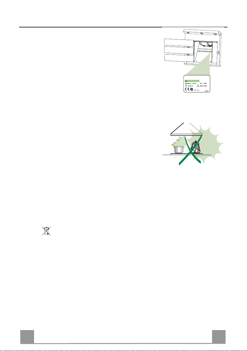
• Check that the mains voltage corresponds to that indicated on the rating plate
fixed to the inside of the hood.
• For Class I appliances, check that the domestic power supply guarantees adequate earthing.
Connect the extractor to the exhaust flue through a pipe of minimum diameter
120 mm. The route of the flue must be as short as possible.
• Do not connect the extractor hood to exhaust ducts carrying combustion fumes
(boilers, fi replaces, etc.).
• If the extractor is used in conjunction with non-electrical appliances (e.g. gas
burning appliances), a sufficient degree of aeration must be guaranteed in the
room in order to prevent the backflow of exhaust gas. The kitchen must have
an opening communicating directly with the open air in order to guarantee the
entry of clea n air.
USE
• The extractor hood has been designed exclusively for domestic use to eliminate kitchen smells.
• Never use the hood f or purposes other than for which it has ben designed.
• Never leave high naked flames under the hood when it is in oper ation.
• Adjust the flame intensity to direct it onto the bottom of the pan only, making
sure that it does not engulf the sides.
• Deep fat fryers must be continuously monitored during use: overheated oil can
burst into flames.
• Do not flambè under the range hood; risk of fir e
• The hood should not be used by children or persons not instructed in its correct use.
MAINTENANCE
• Switch off or unplug the appliance from the mains supply before carrying out
any maintenance work.
• Clean and/or replace the Filters after the specified time p eriod.
• Clean the hood using a damp cloth and a neutral liquid detergent.
The symbol
may not be treated as household waste. Instead it shall be handed over to the
applicable collection point for the recycling of electrical and electronic equipment.
By ensuring this produ ct is disposed of correctly, yo u will help preven t potential
negative consequences for the environment and human health, which could otherwise be caused by inappropriate waste handling of this product. For more detailed information about recycling of this product, please contact your local city
office, your household waste disposal service or the shop where you purchased
the product.
on the product or on its packaging indicates that this product
Page 4
EN 117
CHARACTERISTICS
rols, Light, Blower,
598 / 898
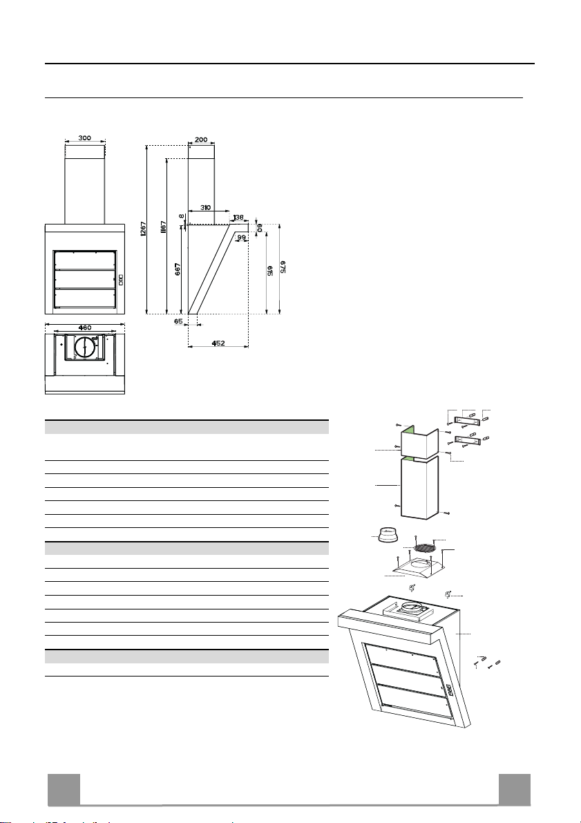
Dimensions
Components
Ref. Q.ty Product Components
1 1 Hood Body, complete with: Cont
Filters
2.1 1 Up per Section
2.2 1 Lower Sectio n
8 1 Directional Air Outlet grille
9 1 Flange
16 1 Filter cover
Ref. Q.ty Installation Components
7.2.1 2 Upper Chimney Section Fixing Brackets
11 6 Wall Plugs
11a 2 Wall Plugs SB 12/10
12a 6 Sc rews 4,2 x 44,4
12c 10 Screws 2,9 x 6, 5
12d 2 Screws 2,9 x 9,5
Q.ty Documentation
1 Instruction Manual
2.1
2.2
9
8
16
12a
7.2.1 11
12c
12d
12c
11a
1
11
12a
Page 5
EN 118
INSTALLATION
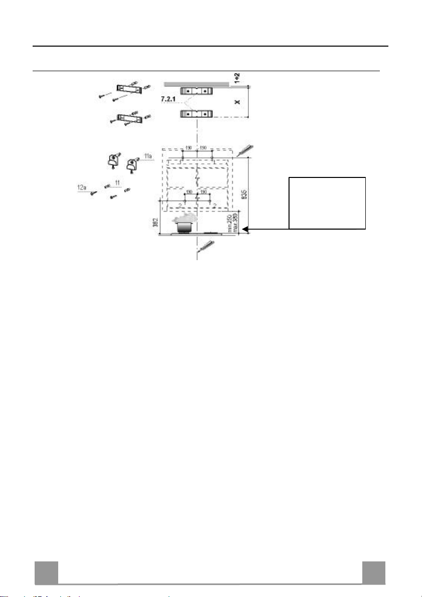
Drilling measures
Wall drilling and bracket fixing
refer to a minimum
On the wall, draw
• a Vertical line up to the ceiling or upper limit, at the centre of the area in which the Hood is
to be fitted;
• a Horizontal line at a mini mum o f 835 mm above the Cooker Top.
• Mark a point (1) on the horizontal line, 190 mm to the right of the vertical reference line.
• Repeat this operat ion on the other side, checking that the two marks are level.
• Mark a reference po int (2) as indicated at 190 mm from the vertical referen ce line and 362
mm above the Cooker Top.
• Repeat this operat ion on the other side, checking that the two marks are level.
• Drill at the points (1) marked, using a ø 12 mm drill bit.
• Drill at the points (2) marked, using a ø 8 mm drill bit.
• Insert the bracket plu gs 11a into the holes 1 and screw into pl ace.
• Insert plug 11 into hole 2.
• Place bracket 7.2.1 on the wall as shown about 1-2 mm from the ceiling or upper limit align-
ing the centre (notch) with the vertical reference line.
• Mark the wall at the cen tres of the holes in the bracket.
• P l ace br acket 7.2.1 on the wall as shown at X mm below the first bracket (X = height of the
upper chimney section supplied), aligning the centre (notch) with the vertical line.
• Mark the wall at the centres of the holes in th e br acket.
• Drill ø 8 mm holes at all the centre points marked.
• Insert the wall plugs 11 in the holes.
• Fix the brackets using the 12a screws (4,2 x 44,4) supplied.
safety distance at
250 mm
Page 6
EN 119
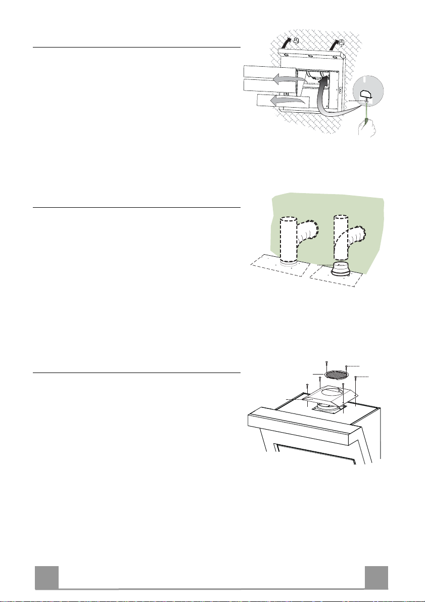
Mounting of the hood body
• Remove the comfort panels pulling them slightly
downwards.
• Remove the grease filters.
• Adjust slightly the Vr screws of the brackets 11a.
• Hang the hood body on the brackets 11a.
• It is possible to level the hood body, from inside the
hood, by adjusting the Vr screws.
• Tighten the security screws 11.
Connections
DUCTED VERSION AIR EXHAUST SYSTEM
When installing the ducted version, connect th e hood to
the chimney using either a flexible or rigid pipe ø 150
or 120 mm, the choice of which is left to the installer.
• To install a ø 120 mm air exhaust connection, insert
the reducer flange 9 on the hood body outlet.
• Fix the pipe in position using sufficient pipe clamps
(not supplied).
• Remove any activated charcoal filters.
ø 150
Vr
ø 120
9
RECYCLING VERSION AIR OUTLET
To install the hood in recycling version, the optional
charcoal filter kit must be purchased.
8
16
12d
12c
• Remove the chimne y fixing angle iron.
• Screw the filter cover onto the air outlet, using four
screws 12c (2.9 x 12.5).
• Fix the air outlet grid 8 on the recirculation air out let
using the 2 screws 12d (2,9 x 9,5) provided.
Page 7
EN 220
ELECTRICAL CONNECTION
12c
2.1
2.2
2
7.2.1
12c
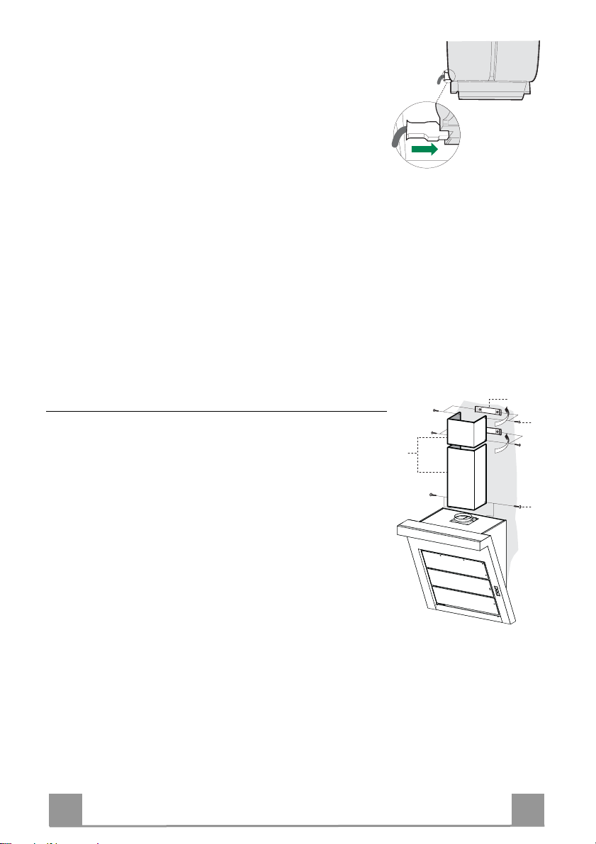
• Connect the hood to the mains through a two-pole switch having a contact gap of at least 3 mm.
• Re move the grease filters (see paragraph Maintenance) being
sure that the conn ector of the feeding cable is correctly inserted
in the socket placed on th e side of the fan.
Chimney assembly
Upper exhaust Chimney
• Slightly widen the two sides of the upper chimney and hook
them behind the brackets 7.2.1, making sure that they are well
seated.
• Secure the sides to the brackets using t he 4 screws 12c (2,9 x
9,5) supplied.
Lower exhaust Chimney
• Slightly widen the two sides of the chimney and hook them
between the upper chimney and the wall, making sure that they
are well seated.
• Fix the lower part laterally to the hood body using the 2 screws
12c (2,9 x 9,5) supplied.
Page 8
EN 221
USE
Switches the extractor motor on an d off at the latest
sible to
A
B
D
C
E
GH
F
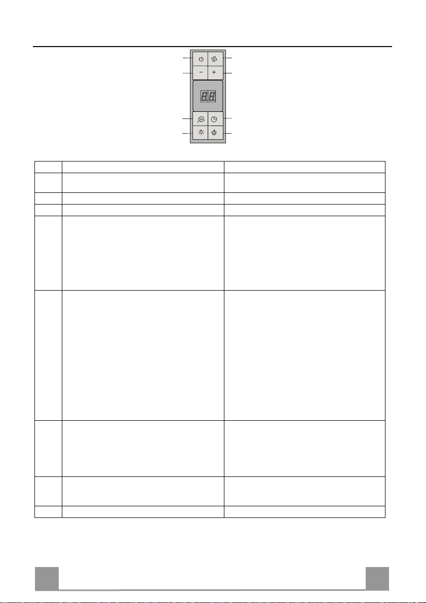
Control board
Key Function Display
A
Indicates the selected speed.
selected speed
Decreases the suction speed.
B
Increases the suction speed.
C
By pressing this key it is possible to activate the
D
intensive speed from any previously selected speed.
The intensive speed can be activated even when
HI appears. The spot down on the right side flashes
once a second.
the motor is OFF. This speed has been timed at 10
minutes. After that time the system activates automatically the latest selected speed. This function is
suitable for cooking conditions when vapours and
smells are of the utmost emis sion.
E By pressing this key it is poss ible to set up the motor
to a suction speed at 100 m
3
/h lasting 10 minutes
every hour. Af ter this the motor switches off automatically.
When the filter saturation is going on it is pos
reset the alarm by pressing this key for about 3 sec-
Indicates the 24-function. The spot down on the
right side flashes and the motor is on.
Once the process is finis hed the previous indication
disappears:
FF Indicates that the metal grease filters satura-
onds. The indication is visible only when the motor
is off.
By pressing this key it is possible to set the delayed
F
shutdown of the appliance to 30 minutes. This function is suitable for a complete elimination of the residual smells. It can be activated at any position,
EF Indicates that the charcoal filter saturation
Indicates al ternately the selected speed of the hoo d
and the time left before the hood shutdown. The
spot down on the right side flashes.
and it is deactivated by pressing the key again or by
switching of f the motor.
Turns light o n and off .
G
When pressed for about 2 seconds the upper lighting switches on (only in th e 90 cm hood version).
Turns light o n and off at reduced intensity.
H
tion alarm has been triggered, and the filters
need to be washed. The alarm is triggered after 100 working hours.
alarm has been triggered, and the filter has to
be replaced; the metal grease filters must
also be washed. The charcoal filter is triggered after 20 0 work i ng hour s .
Page 9
EN 222
MAINTENANCE
REMOTE CONTROL (OPTIONAL)
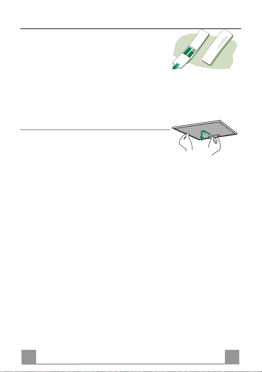
The appliance can be controlled using a remote control powered
by a 1.5 V carbon-zinc alkaline batteries of the standard LR03AAA type.
• Do not place the remote control near to heat sources.
• Used batteries must be disposed of in the proper manner.
Metal grease filters
Metal filters can be washed also in a dish machine. They need to
be washed every time a FF-symbol appears in the display or at
least every two months. In case of very frequent use these have to
be washed even more often.
Alarm reset
• Switch off the lights and the motor. If the 24h mode is activated it is necessary to switch it off.
• Press the E-key until the display is unlit.
Cleaning
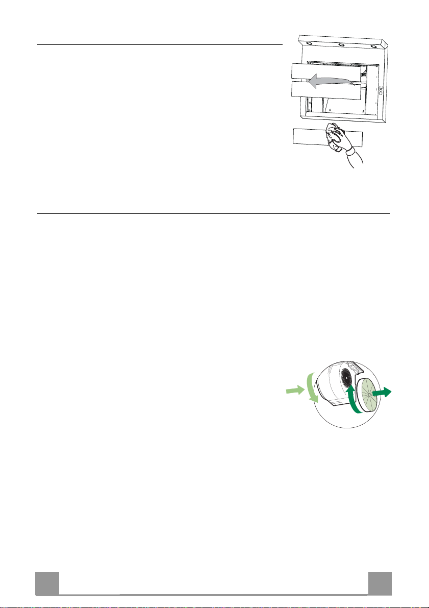
• Open the comfort panel pulling them slightly.
• Remove the filters one by one by pushing them backwards and
pulling them down contemporaneously.
• Wash the filters. Pay attention not to bend them. Make sure
that filters are completely dry before putting them into their
seat. (a possible modification of the filter surface doesn’t influence its efficiency).
• Place the filters again into their seats and make sure that the
handle of the filter remains outside.
• Close the comfort panel.
Page 10
EN 223
Comfort panels
A
B
• Remove the comfort panels pulling them slightly.
• It is recommended to use a neutral detergent liquid and a damp
cloth when washing the outer surface of the comfort panel.
• Wash the inner part of the panel as well by using a neutral detergent liquid and a damp cloth; in any case do not use wet
sponges or other clothes nor water jet or corrosive detergents.
• Let the get dry, and pl ace them again in their correct position.
Charcoal filter (recycling version)
• This filter cannot be washed or regenerated. It must be replaced when the EF appears on the
display or at least once every 4 months.
Activation of the alarm signal
• In the recycling version hoods the filter saturation alarm must be activated during the installation or later.
• Switch off the hood and the lights.
• Disconnect the hood from the mains supply.
• When restoring the connection press and hold B-key.
• When releasing the key two rotating rectangles appear on the display.
• Within 3 seconds press th e B-key until a flashing confirmation appears on the dispaly:
• 2 flashes with EF - charcoal filter saturation alarm ACTIVATED
• 1 flash with EF - charcoal filter saturation alarm DEACTIVATED.
REPLACING THE CHARCOAL FILTER
Reset of the alarm signal
• Switch off the hood and the lighting. If the 24h-function has
been activated this has to be deactivated.
• Press the E-key until the display is unlit.
Replacing of the filter
• Remove the comfort panels pulling them slightly.
• Remove the grease filters.
• Remove the saturated charcoal filter as indicated (A).
• Place the new filetrs as indicated (B).
• Put the metal grease filters into their seats.
• Place the comfort p anels into their seats again.
Page 11
EN 224
Lighting system
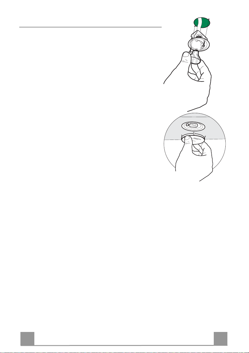
REPLACING OF THE LAMPS
20 W halogen lamps
• Loose the 2 fixing screws of the lighting support and remove
the support from the hood.
• Take off the lamp from the support.
• Replace the la mp with a new one. Make su re that the pins are
correctly seated in the sup port.
• Place the support again in its place. Fix it with the screws
which were earlier removed.
The 90 cm hood version is equipped with halogen lamps (20W)
placed in the upper part of the hood.
When replacing the lamps proceed as follows:
• Remove the metallic glass holder by levering it from under the
metal ring, supporting it with one hand.
• Remove the halogen lamp from the lamp holder.
• Replace the la mp with a new one. Make su re that the pins are
correctly seated in the sup port.
• Place the glass holder again in its place.
Page 12

Dir. 89/336/CEE
73/23/CEE
93/68/CEE
Franke S.p.a.
Via Pignolini,2
37019 Peschiera d el Garda (VR)
www.franke.it
436003664_ver1
 Loading...