

Page 1

Instructions for use and installation
Cooker Hood
Príručka na obsluhu
Odsávač
FAK 607
FAK 907
SK
GB
Page 2
2
INDEX
RECOMMENDATIONS AND SUGGESTIONS.....................................................................................................................3
CHARACTERISTICS.............................................................................................................................................................4
INSTALLATION......................................................................................................................................................................5
USE........................................................................................................................................................................................8
MAINTENANCE.....................................................................................................................................................................9
OBSAH
RADY A ODPORÚČANIA....................................................................................................................................................12
CHARAKTERISTIKY............................................................................................................................................................13
INŠTALÁCIA........................................................................................................................................................................14
POUŽÍVANIE........................................................................................................................................................................17
ÚDRŽBA...............................................................................................................................................................................18
EN
SK
Page 3
3
RECOMMENDATIONS AND SUGGESTIONS
The Instructions for Use apply to several versions of this appliance. Accor
d-
ingly, you may find descriptions of individual features that do not apply to
your specific appliance.
INSTALLATION
• The manufacturer will not be held liable for any damages resulting from incorrect or improper installation.
• The minimum safety distance between the cooker top and the extractor
hood is 650 mm (some models can be installed at a lower height, please refer to the paragraphs on working dimensions and installation).
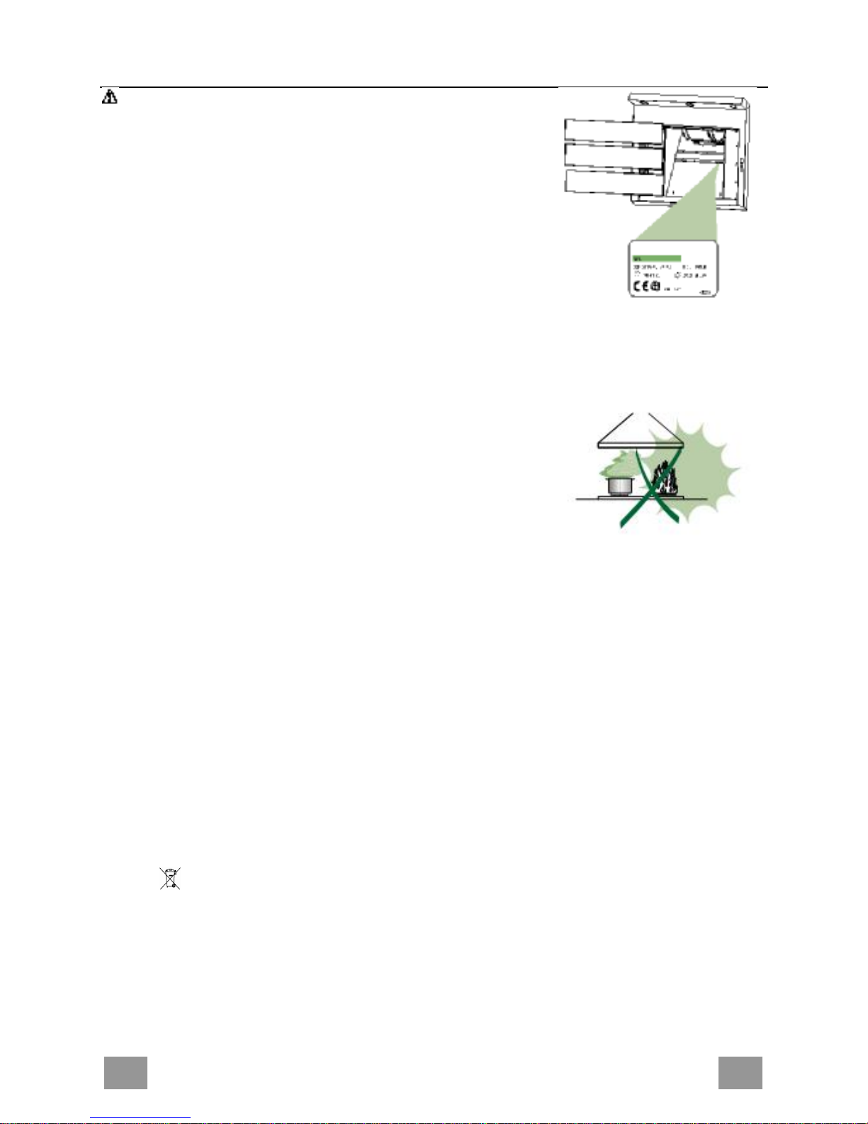
• Check that the mains voltage corresponds to that indicated on the rating
plate fixed to the inside of the hood.
• For Class I appliances, check that the domestic power supply guarantees
adequate earthing.
Connect the extractor to the exhaust flue through a pipe of minimum diame-
ter 120 mm. The route of the flue must be as short as possible.
• Do not connect the extractor hood to exhaust ducts carrying combustion
fumes (boilers, fireplaces, etc.).
• If the extractor is used in conjunction with non-electrical appliances (e.g. gas
burning appliances), a sufficient degree of aeration must be guaranteed in
the room in order to prevent the backflow of exhaust gas. The kitchen must
have an opening communicating directly with the open air in order to gua rantee the entry of clean air.
USE
• The extractor hood has been designed exclusively for domestic use to eliminate kitchen smells.
• Never use the hood for purposes other than for which it has been designed.
• Never leave high naked flames under the hood when it is in operation.
• Adjust the flame intensity to direct it onto the bottom of the pan only, making
sure that it does not engulf the sides.
• Deep fat fryers must be continuously monitored during use: overheated oil
can burst into flames.
• Do not flambè under the range hood; risk of fire
• This appliance is not intended for use by persons (including children) with
reduced physical, sensory or mental capabilities, or lack of experience and
knowledge, unless they have been given supervision or instruction concerning use of the appliance by a person responsible for their safety.
• Children should be supervised to ensure that they do not play with the appliance.
MAINTENANCE
• Switch off or unplug the appliance from the mains supply before carrying out
any maintenance work.
• Clean and/or replace the Filters after the specified time period (Fire hazard).
• Clean the hood using a damp cloth and a neutral liquid detergent.
The symbol on the product or on its packaging indicates that this product may not be treated
as household waste. Instead it shall be handed over to the applicable collection point for the
recycling of electrical and electronic equipment. By ensuring this product is disposed of correctly,
you will help prevent potential negative consequences for the environment and human health,
which could otherwise be caused by inappropriate waste handling of this product. For more
detailed information about recycling of this product, please contact your local city office, your
household waste disposal service or the shop where you purchased the product.
Page 4
4
CHARACTERISTICS
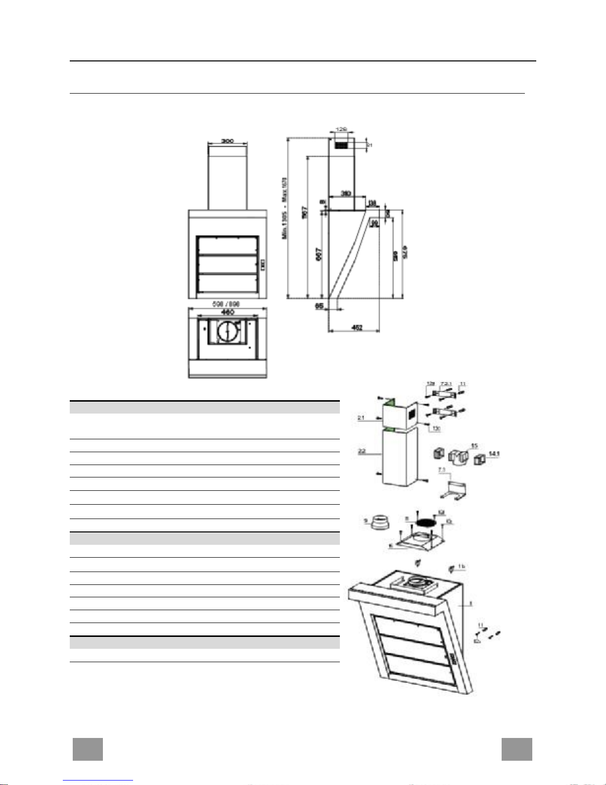
Dimensions
Components
Ref. Q.ty Product Components
1 1
Hood Body, complete with: Controls, Light, Blower,
Filters
2.1 1 Upper Section
2.2 1 Lower Section
8 1 Directional Air Outlet grille
9 1 Flange
14.1 2 Air Outlet Connection Extension
15 1 Air Outlet Connection
16 1 Filter cover
Ref. Q.ty Installation Components
7.2.1 2 Upper Chimney Section Fixing Brackets
7.3 1 Air Outlet Connection Support
11 6 Wall Plugs
11a 2 Wall Plugs SB 12/10
12a 6 Screws 4,2 x 44,4
12c 10 Screws 2,9 x 6,5
12d 2 Screws 2,9 x 9,5
Q.ty Documentation
1 Instruction Manual
Page 5
5
INSTALLATION
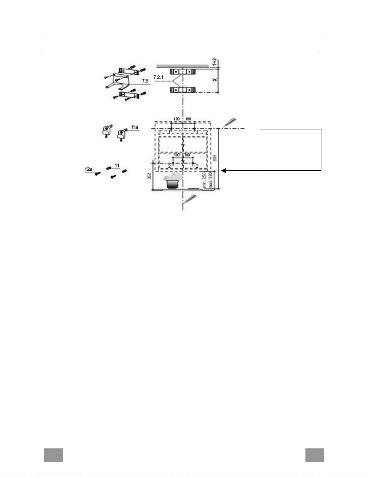
Wall drilling and bracket fixing
On the wall, draw
• a Vertical line up to the ceiling or upper limit, at the centre of the area in which the Hood is
to be fitted;
• a Horizontal line at a minimum of 835 mm above the Cooker Top.
• Mark a point (1) on the horizontal line, 190 mm to the right of the vertical reference line.
• Repeat this operation on the other side, checking that the two marks are level.
• Mark a reference point (2) as indicated at 190 mm from the vertical reference line and 362
mm above the Cooker Top.
• Repeat this operation on the other side, checking that the two marks are level.
• Drill at the points (1) marked, using a ø 12 mm drill bit.
• Drill at the points (2) marked, using a ø 8 mm drill bit.
• Insert the bracket plugs 11a into the holes 1 and screw into place.
• Insert plug 11 into hole 2.
To install a decorative chimney ( optional )
• Place bracket 7.2.1 on the wall as shown about 1-2 mm from the ceiling or upper limit aligning the centre (notch) with the vertical reference line.
• Mark the wall at the centres of the holes in the bracket.
• Place bracket 7.2.1 on the wall as shown at X mm below the first bracket (X = height of the
upper chimney section supplied), aligning the centre (notch) with the vertical line.
• Mark the wall at the centres of the holes in the bracket.
• Drill ø 8 mm holes at all the centre points marked.
• Insert the wall plugs 11 in the holes.
• Fix the lower bracket 7.2.1 using the 12a screws (4,2 x 44,4) supplied.
• Fix the upper bracket 7.2.1 and the air outlet connection support 7.3 together using the 2
screws 12a (4,2 x 44,4) supplied.
Drilling measures
refer to a minimum
safety distance at
250 mm
Page 6
6
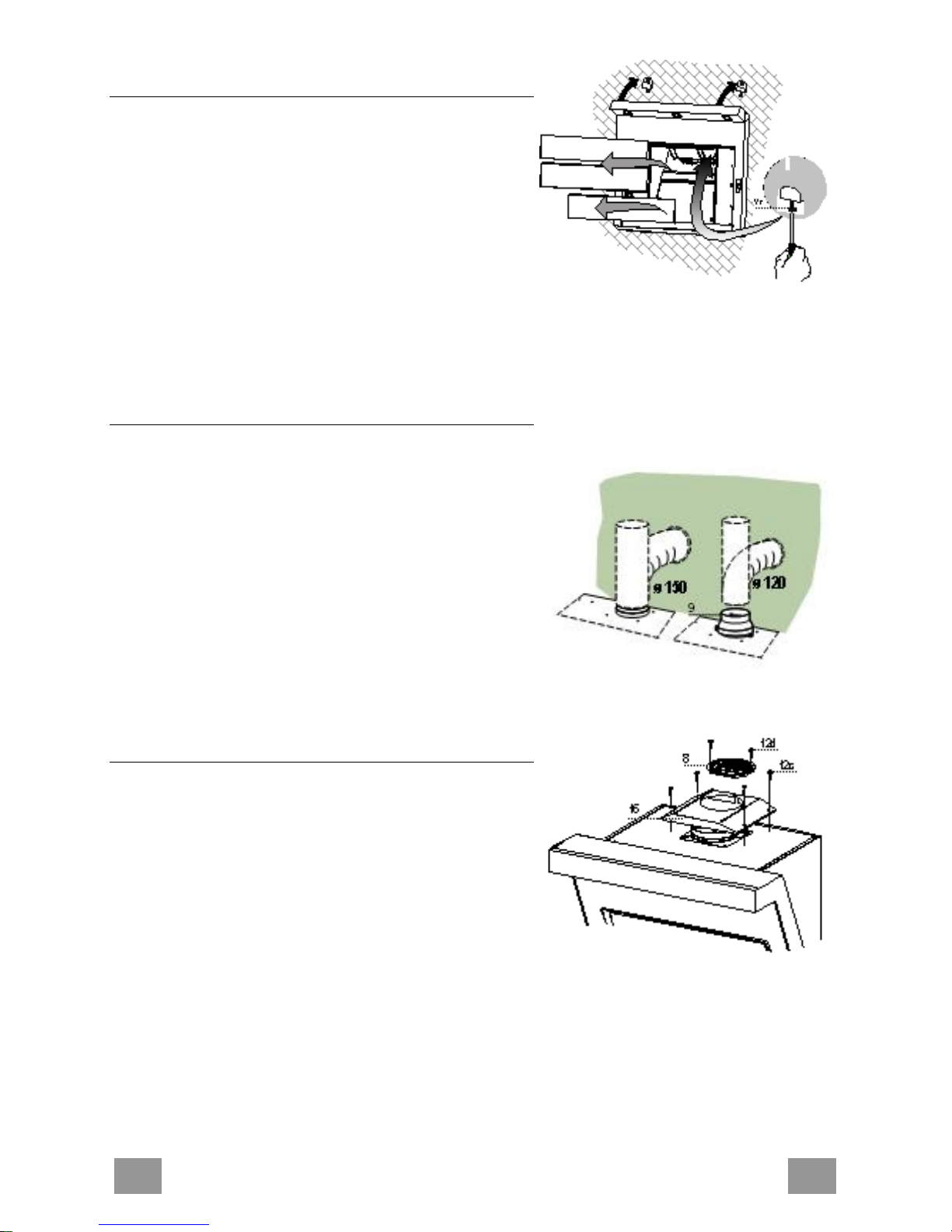
Mounting of the hood body
• Remove the comfort panels pulling them slightly
downwards.
• Remove the grease filters.
• Adjust slightly the Vr screws of the brackets 11a.
• Hang the hood body on the brackets 11a.
• It is possible to level the hood body, from inside the
hood, by adjusting the Vr screws.
• Tighten the security screws 11.
Connections
DUCTED VERSION AIR EXHAUST SYSTEM
When installing the ducted version, connect the hood to
the chimney using either a flexible or rigid pipe ø 150
or 120 mm, the choice of which is left to the installer.
• To install a ø 120 mm air exhaust connection, insert
the reducer flange 9 on the hood body outlet.
• Fix the pipe in position using sufficient pipe clamps
(not supplied).
• Remove any activated charcoal filters.
RECYCLING VERSION AIR OUTLET
To install the hood in recycling version, the optional
charcoal filter kit must be purchased.
• Remove the chimney angle bracket.
• Screw the filter cover onto the air outlet, using four
screws 12c (2.9 x 12.5).
• Fix the air outlet grid 8 on the recirculation air outlet
using the 2 screws 12d (2,9 x 9,5) provided.
Page 7
7
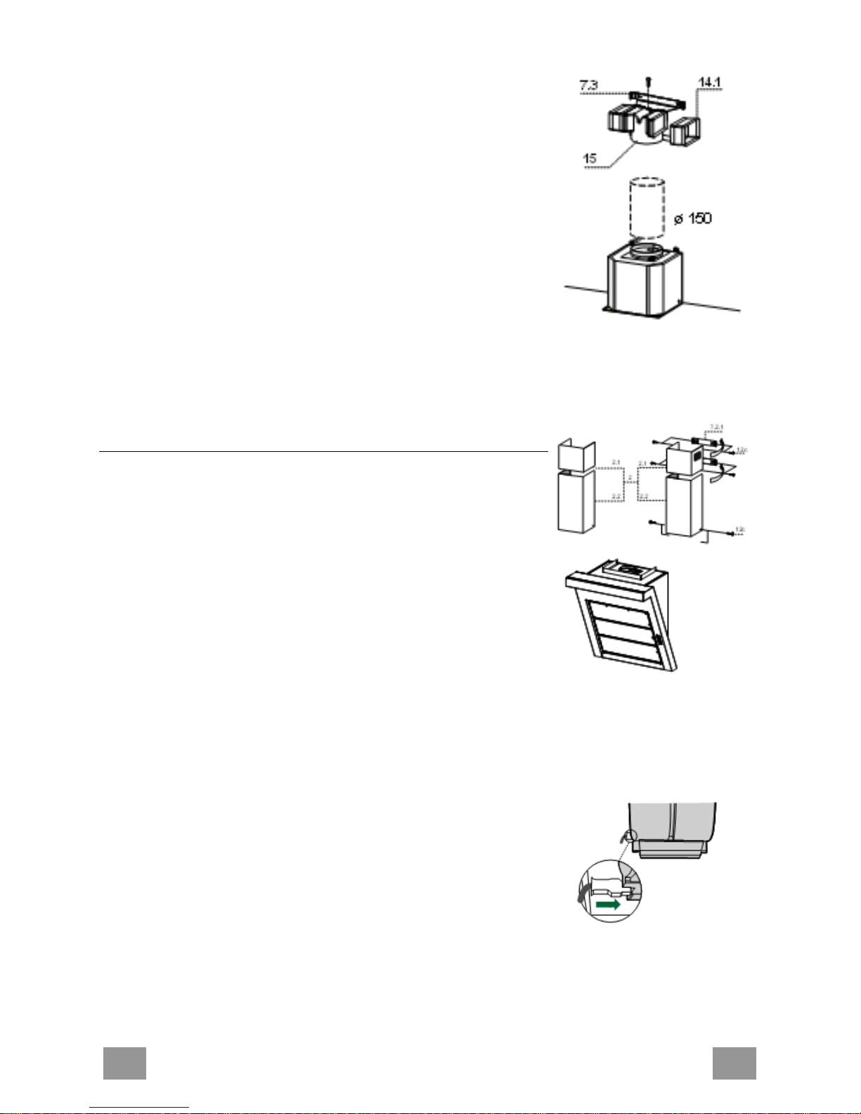
RECIRCULATION VERSION AIR OUTLET
• Insert the connection extension pieces laterally 14.1 in connection 15.
• Insert the Connector 15 into the Support bracket 7.3 and fix it
with a screw.
• Make sure that the outlet of the extension pieces 14.1 is horizontally and vertically aligned with the chimney outlets.
• Connect the air outlet connection 15 to the hood body outlet
using either a flexible or rigid pipe ø 150 mm, the choice of
which is left to the installer.
• Ensure that the activated charcoal filters have been inserted.
Chimney assembly
Upper exhaust Chimney
• Slightly widen the two sides of the upper chimney and hook
them behind the brackets 7.2.1, making sure that they are well
seated.
• Secure the sides to the brackets using the 4 screws 12c (2,9 x
9,5) supplied.
Lower exhaust Chimney
• Slightly widen the two sides of the chimney and hook them
between the upper chimney and the wall, making sure that they
are well seated.
• Fix the lower part laterally to the hood body using the 2 screws
12c (2,9 x 9,5) supplied.
ELECTRICAL CONNECTION
• Connect the hood to the mains through a two-pole switch having a contact gap of at least 3 mm.
• Remove the grease filters (see paragraph Maintenance) being
sure that the connector of the feeding cable is correctly inserted
in the socket placed on the side of the fan.
Page 8

8
USE
Control board
Key Function Display
A
Switches the extractor motor on and off at the latest
selected speed
Indicates the selected speed.
B
Decreases the suction speed.
C
Increases the suction speed.
D
By pressing this key it is possible to activate the
intensive speed from any previously selected speed.
The intensive speed can be activated even when
the motor is OFF. This speed has been timed at 10
minutes. After that time the system activates automatically the latest selected speed. This function is
suitable for cooking conditions when vapours and
smells are of the utmost emission.
HI appears. The spot down on the right side flashes
once a second.
E By pressing this key it is possible to set up the motor
to a suction speed at 100 m3/h lasting 10 minutes
every hour. After this the motor switches off automatically.
When the filter saturation is going on it is pos
sible to
reset the alarm by pressing this key for about 3 seconds. The indication is visible only when the motor
is off.
Indicates the 24-function. The spot down on the
right side flashes and the motor is on.
Once the process is finished the previous indication
disappears:
FF Indicates that the metal grease filters satura-
tion alarm has been triggered, and the filters
need to be washed. The alarm is triggered after 100 working hours.
EF Indicates that the charcoal filter saturation
alarm has been triggered, and the filter has to
be replaced; the metal grease filters must
also be washed. The charcoal filter is triggered after 200 working hours.
F
By pressing this key it is possible to set the delayed
shutdown of the appliance to 30 minutes. This function is suitable for a complete elimination of the residual smells. It can be activated at any position,
and it is deactivated by pressing the key again or by
switching off the motor.
Indicates alternately the selected speed of the hood
and the time left before the hood shutdown. The
spot down on the right side flashes.
G
Turns light on and off .
When pressed for about 2 seconds the upper lighting switches on (only in the 90 cm hood version).
H
Turns light on and off at reduced intensity.
Page 9

9
MAINTENANCE
REMOTE CONTROL (OPTIONAL)
The appliance can be controlled using a remote control powered
by a 1.5 V carbon-zinc alkaline batteries of the standard LR03AAA type.
• Do not place the remote control near to heat sources.
• Used batteries must be disposed of in the proper manner.
Metal grease filters
Metal filters can be washed also in a dish machine. They need to
be washed every time a FF-symbol appears in the display or at
least every two months. In case of very frequent use these have to
be washed even more often.
Alarm reset
• Switch off the lights and the motor. If the 24h mode is activated it is necessary to switch it off.
• Press the E-key until the display is unlit.
Cleaning
• Open the comfort panel pulling them slightly.
• Remove the filters one by one by pushing them backwards and
pulling them down contemporaneously.
• Wash the filters. Pay attention not to bend them. Make sure
that filters are completely dry before putting them into their
seat. (a possible modification of the filter surface doesn’t influence its efficiency).
• Place the filters again into their seats and make sure that the
handle of the filter remains outside.
• Close the comfort panel.
Page 10

1
Comfort panels
• Remove the comfort panels pulling them slightly.
• It is recommended to use a neutral detergent liquid and a damp
cloth when washing the outer surface of the comfort panel.
• Wash the inner part of the panel as well by using a neutral detergent liquid and a damp cloth; in any case do not use wet
sponges or other clothes nor water jet or corrosive detergents.
• Let the get dry, and place them again in their correct position.
Charcoal filter (recycling version)
• This filter cannot be washed or regenerated. It must be replaced when the EF appears on the
display or at least once every 4 months.
Activation of the alarm signal
• In the recycling version hoods the filter saturation alarm must be activated during the installation or later.
• Switch off the hood and the lights.
• Disconnect the hood from the mains supply.
• When restoring the connection press and hold B-key.
• When releasing the key two rotating rectangles appear on the display.
• Within 3 seconds press the B-key until a flashing confirmation appears on the dispaly:
• 2 flashes with EF - charcoal filter saturation alarm ACTIVATED
• 1 flash with EF - charcoal filter saturation alarm DEACTIVATED.
REPLACING THE CHARCOAL FILTER
Reset of the alarm signal
• Switch off the hood and the lighting. If the 24h-function has
been activated this has to be deactivated.
• Press the E-key until the display is unlit.
Replacing of the filter
• Remove the comfort panels pulling them slightly.
• Remove the grease filters.
• Remove the saturated charcoal filter as indicated (A).
• Place the new filetrs as indicated (B).
• Put the metal grease filters into their seats.
• Place the comfort panels into their seats again.
Page 11

1
Lighting system
REPLACING OF THE LAMPS
20 W halogen lamps
• Loose the 2 fixing screws of the lighting support and remove
the support from the hood.
• Take off the lamp from the support.
• Replace the lamp with a new one. Make sure that the pins are
correctly seated in the support.
• Place the support again in its place. Fix it with the screws
which were earlier removed.
The 90 cm hood version is equipped with halogen lamps (20W)
placed in the upper part of the hood.
When replacing the lamps proceed as follows:
• Remove the metallic glass holder by levering it from under the
metal ring, supporting it with one hand.
• Remove the halogen lamp from the lamp holder.
• Replace the lamp with a new one. Make sure that the pins are
correctly seated in the support.
• Place the glass holder again in its place.
Page 12

1
RADY A ODPORÚČANIA
Tento Návod na používanie je určený pre viac verzií spotrebiča. Je možné, že
v ňom budú popísané dodávané časti, ktoré nie sú súčasťou Vášho spotrebiča.
INŠTALÁCIA
• Výrobca odmieta akúkoľvek zodpovednosť za škody spôsobené nesprávnou
inštaláciou alebo v prípade, že pri inštalácii nebudú dodržané všetky platné technické normy.
• Minimálna bezpečná vzdialenosť medzi varnou doskou a odsávačom pár musí
byť aspoň 650 mm (niektoré modely možno nainštalovať aj v nižšej výške, post u-
pujte podľa odsekov s údajmi o rozmeroch a inštalácii).
• Skontrolujte, či napätie v elektrickej sieti zodpovedá napätiu uvedenému na štítku
nachádzajúcom sa vnútri odsávača pár.
• U spotrebičov Triedy Ia skontrolujte, či je elektrická sieť domácnosti správne u-
zemnená.
• Zapojte odsávač pár k vývodnému potrubiu nasávaných pár pomocou rúry s
priemerom rovným alebo väčším ako 120 mm. Vedenie potrubia má byť podľa
možnosti čo najkratšie.
• Nezapájajte odsávač pár k odvodom dymov z horenia (kotly, kozuby a pod.).
• V prípade, že v miestnosti sa používajú okrem odsáva ča pár aj spotrebiče bez
napájania elektrinou (napríklad plynové spotrebiče), musíte zabezpečiť dostatoč-
né vetranie prostredia. Ak by kuchyňa nebola vybavená vetracím otvorom, musí-
te zabezpečiť otvor komunikujúci s vonkajším prostredím, aby bol zabezpečený
prívod čistého vzduchu.
POUŽÍVANIE
• Odsávač pár bol navrhnutý výhradne na použitie v domácnosti, aby odstraňoval
pachy z varenia.
• Odsávač pár nikdy nepoužívajte na iné účely.
• Pod zapnutým odsávačom pár nikdy nenechávajte voľné vysoké plamene.
• Plamene vždy nastavte tak, aby sa predišlo ich bočnému úniku vzh ľadom na dno
hrncov a panvíc.
• Fritézy počas používania kontrolujte: Rozpálený olej by sa mohol vznietiť.
• Pod odsávačom pár nepripravujte flambované jedlá; hrozí nebezpečenstvo po-
žiaru.
• Tento spotrebič nesmú používať osoby (vrátane detí) so zníženými psychickými,
zmyslovými alebo rozumovými schopnosťami, ani osoby, ktoré nemajú dostatok
skúseností a znalostí, ak nie sú pod dozorom alebo ak neboli poučené o použí-
vaní spotrebiča osobami zodpovednými za ich bezpečnosť.
• Na deti vždy dohliadajte, aby ste zabezpečili, že sa so spotrebičom nebudú hra ť.
ÚDRŽBA
• Pred akýmkoľvek úkonom údržby odsávač pár odpojte od elektrickej siete vytia hnutím zástrčky alebo vypnutím hlavného vypínača.
• V odporúčaných intervaloch vykonávajte pravidelnú a dôslednú údržbu filtrov
(Riziko požiaru).
• Na čistenie vonkajšieho povrchu odsávača pár používajte vlhkú handru
a neutrálny kvapalný čistiaci prostriedok.
Symbol na spotrebiči alebo na sprievodných dokumentoch znamená, že s týmto výrobkom
sa nesmie zaobchádzať ako s mestským odpadom, ale treba ho odovzdať v určenom zbernom
stredisku na recykláciu elektrických a elektronických zariadení. Zabezpečte, že tento výrobok
bude zlikvidovaný správnym postupom, aby ste predišli negatívnym dopadom na životné prostredie a ľudské zdravie, ktoré by mohli vzniknúť nesprávnym postupom pri jeho likvidácii. Po-
drobnejšie informácie o zaobchádzaní, zbere a recyklácii tohto spotrebi ča si vyžiadajte na miestnom úrade, v zbernom stredisku domácich spotrebičov alebo v obchode, kde ste spotrebič kúpili.
Page 13

1
CHARAKTERISTIKY
Vonkajšie rozmery
Časti
Ozn.Množstvo Časti spotrebiča
1 1 Teleso odsávača vybavené časťami: Ovládač,
osvetlenie, jednotka ventilátora, filtre
2.1 1 Horný komín
2.2 1 Spodný komín
8 1 Mriežka výstupu vzduchu s nasmerovaním
9 1 Redukčná príruba 150-120
14.1 2 Predlžovacia spojka výstupu vzduchu
15 1 Spojka výstupu vzduchu
16 1 Filtračný uzáver
Ozn.Množstvo Časti pri inštalácii
7.2.1 2 Upevňovacie konzoly horného komína
7.3 1 Podporná konzola spojky
11 6 Hmoždinky
11a 2 Hmoždinky SB 12/10
12a 6 Skrutky 4,2 x 44,4
12c 10 Skrutky 2,9 x 6,5
12d 2 Skrutky 2,9 x 9,5
Množstvo Dokumentácia
1 Návod s pokynmi
Page 14

1
INŠTALÁCIA
Vyvŕtanie otvorov a upevnenie konzol
Naznačte na stenu:
• vertikálnu čiaru až po strop alebo až po horný okraj v strede oblasti, kde bude namontovaný odsávač
pár;
• vodorovnú čiaru vo vzdialenosti min. 835 mm nad varnou doskou.
• Naznačte bod (1) na vodorovnej čiare vo vzdialenosti 190 mm vpravo od zvislej referenčnej čiary.
• Zopakujte túto operáciu na opačnej strane, skontrolujte vodorovnú polohu.
• Podľa obrázku naznačte referenčný bod (2) 190 mm od referenčnej vertikálnej čiary a 362 mm nad
varnou doskou.
• Zopakujte túto operáciu na opačnej strane, skontrolujte vodorovnú polohu.
• V naznačených otvoroch (1) vyvŕtajte otvory s priemerom ø 12 mm.
• V naznačených otvoroch (2) vyvŕtajte otvory s priemerom ø 8 mm.
• Vsuňte hmoždinky s konzolou 11a do otvorov (1) a zaskrutkujte.
• Do otvorov 2 vsuňte hmoždinky 11.
Pri inštalácii dekoratívneho komína: (Doplnkový)
• Podľa pokynov oprite konzolu 7.2.1 vo vzdialenosti 1-2 mm od stropu alebo od horného okraja,
zarovnajúc jej stred (zárezy) podľa referenčnej vertikálnej čiary.
• Naznačte stredy otvorov konzoly.
• Podľa pokynov oprite konzolu 7.2.1 vo vzdialenosti X mm pod prvou konzolou (X = výška horného
dodávaného komína), zarovnajúc jej stred (zárezy) podľa referenčnej vertikálnej čiary.
• Naznačte stredy otvorov konzoly.
• V naznačených otvoroch vyvŕtajte otvory s priemerom ø 8 mm.
• Do otvorov vsuňte hmoždinky 11.
• Upevnite spodnú konzolu 7.2.1 použitím dodávaných skrutiek 12a (4,2 x 44,4 ).
• Upevnite spolu hornú konzolu 7.2.1 a podpornú konzolu spojky 7.3 použitím 2 dodávaných skrutiek
12a (4,2 x 44,4).
Vzdialenosti vŕtania
otvorov sa vzťahujú na
minimálnu bezpečnú
vzdialenosť 250 mm
Page 15

1
Montáž telesa odsávača pár
• Odpojte nasávacie panely ich potiahnutím.
• Vyberte tukové filtre potiahnutím príslušných
rukovätí.
• Nastavte dve skrutky Vr, konzol 11a, na začiatok
uťahovania.
• Zaveste teleso odsávača pár na 2 konzoly 11a.
• Z vnútra telesa pomocou skrutiek Vr vyrovnajte
teleso odsávača do vodorovnej polohy.
• Zaskrutkujte bezpečnostné skrutky 11..
Výstup vzduchu vo verzii s filtrovaním
Pri inštalácii odsávača vo verzii s filtrovaním je nevyhnutné
kúpiť doplnkovú súpravu Vložka s aktívnym uhlíkom.
• Vyberte uhlový prvok upevnenia komína
• Zaskrutkujte filtračný kryt použitím štyroch skrutiek 12c
(2,9 x 6,5).
• Vysúvateľnú mriežku 8 namontujte na výstup recyklovaného vzduchu 2 dodávanými skrutkami 12d (2,9 x 9,5).
Page 16

1
VÝSTUP VZDUCHU VO VERZII S FILTROVANÍM
• Vsuňte bočne predĺženia spojky 14.1 na spojku 15.
• Vsuňte spojku 15 do podpornej konzoly 7.3 upevniac ju jednou
skrutkou.
• Skontrolujte, či je výstup predĺžení spojky 14.1 v mieste výstupu komína vo vodorovnej, ako aj vo vertikálnej polohe.
• Zapojte spojku 15 na výstup telesa odsávača pár pomocou neohybnej alebo ohybnej rúrky s priemerom ø150 mm, podľa
voľby pracovníka, ktorý vykonáva inštaláciu.
• Skontrolujte, či sú na odsávači pár protipachové filtre s aktívnym uhlíkom.
Montáž komína
Horný komín
• Mierne rozšírte dve bočné krídla, zachyťte ich za konzolami
7.2.1 a zatvorte až nadoraz.
• Upevnite konzoly na boku pomocou dodávaných 4 skrutiek
12c (2,9 x 9,5).
Spodný komín
• Mierne rozšírte dve bočné krídla komína, zachyťte ich medzi
horný komín a stenu a zatvorte ich nadoraz.
• Upevnite na boku spodnú časť telesa odsávača pár 2 dodávanými skrutkami 12c (2,9 x 6,5).
Page 17

1
POUŽÍVANIE
Ovládací panel
Tlačidlo Funkcia Displej
A Zapne a vypne motor nasávania pri posledne používanej
rýchlosti.
Zobrazí nastavenú rýchlosť
B Zníženie pracovnej rýchlosti.
C Zvýšenie pracovnej rýchlosti.
D Aktivuje intenzívnu rýchlosť z ľubovoľnej rýchlosti, aj pri
vypnutom motore, táto rýchlosť trvá 10 minút, po tejto
dobe sa systém vráti k predchádzajúcej nastavenej
rýchlosti. Vhodná na odsávanie veľmi veľkých množstiev
pár z varenia.
Zobrazuje HI a bodka dolu vpravo bliká s
frekvenciou raz za sekundu.
E Aktivuje motor pri rýchlosti, ktorá umožňuje nasávanie 100
m3/h počas 10 minút za každú hodinu, po uplynutí tejto
doby sa motor zastaví.
Keď je aktívny alarm filtrov, stlačením tlačidla na približne
3 sekundy sa alarm zruší. Tieto signalizácie vidno iba pri
vypnutom motore.
Zobrazuje 24 a bodka dolu vpravo bliká, zatiaľ
čo motor je v chode.
Po ukončení procedúra sa predtým
zobrazovaná signalizácia vypne:
FF signalizuje potrebu umyť tukové kovové
filtre. Alarm sa zapne po 100
vykonaných pracovných hodinách
odsávača pár.
EF signalizuje potrebu vymeniť filtre s
aktívnym uhlíkom a treba umyť aj
tukové kovové filtre. Alarm sa zapne po
200 vykonaných pracovných hodinách
odsávača pár.
F Aktivuje automatické vypnutie s odložením 30’. Vhodná na
ukončenie odstránenia zvyškových pachov. Aktivuje sa z
ľubovoľnej polohy, vypína sa stlačením tlačidla alebo
vypnutím motora.
Zobrazuje striedavo pracovnú rýchlosť a
zostávajúcu dobu do vypnutia odsávača pár.
Bodka dolu vpravo bliká.
G Zapne a vypne zariadenie osvetlenia.
Iba u verzie odsávača pár s šírkou 90 cm, ak ho podržíte
stlačené približne 2 sekundy, zapne horné osvetlenie
H Zapne a vypne zariadenie osvetlenia so zníženou
intenzitou.
Page 18

1
ÚDRŽBA
DIAĽKOVÝ OVLÁDAČ (DOPLNKOVÝ)
Tento spotrebič sa dá ovládať prostredníctvom diaľkového ovládača napájaného alkalickými zinko-uhlíkovými batériami 1,5
V štandardného typu LR03-AAA.
• Diaľkový ovládač neklaďte do blízkosti zdrojov tepla.
• Batérie nevyhadzujte voľne, ale vhadzujte ich do príslušných
odpadových nádob.
Tukové kovové filtre
Môžu sa umývať aj v umývačke riadu, pričom ich treba umývať,
keď sa na displeji zobrazí FF alebo aspoň každé 2 mesiace
činnosti alebo aj častejšie, pri mimoriadne častom a intenzívnom
používaní.
Zrušenie signálu alarmu
• Vypnite osvetlenie a motor nasávania, potom, ak by bola
aktívna funkcia 24h, vypnite ju.
• Podržte stlačené tlačidlo E, kým nezhasne displej.
Čistenie filtrov
• Vyberte panel komfort ich potiahnutím.
• Vyberte filtre po jednom, pričom ich zatlačte smerom do
zadnej časti a súčasne potiahnite dolu.
• Filtre umyte, pričom dbajte, aby sa neohýnali a pred
opätovným namontovaním ich nechajte vysušiť. (Prípadná
zmena farby povrchu filtra, ku ktorej by mohlo časom dôjsť, v
žiadnom prípade neznižuje jeho účinnosť.)
• Namontujte ich späť, pričom dávajte pozor, aby rukoväť ostala
otočená smerom vonku.
• Panel komfort namontujte na miesto.
Page 19

1
Nasávacie panely
• Vyberte nasávacie panely ich potiahnutím.
• Očistite ich povrch vlhkou handrou a neutrálnym kvapalným
čistiacim prostriedkom.
• Panel vyčistite aj z vnútra pomocou vlhkej handry a
neutrálneho čistiaceho prostriedku; nepoužívajte mokré handry
alebo špongie, ani prúd vody a nepoužívajte abrazívne čistiace
prostriedky.
• Nechajte ich osušiť a namontujte ich na miesto.
Protipachové filtre s aktívnym uhlíkom (Verzia s filtrovaním)
• Nedá sa umývať, ani regenerovať, treba ho vymeniť, keď sa na displeji zobrazí EF alebo
aspoň každé 4 mesiace.
Aktivácia signálu alarmu
• U odsávačov pár vo verzii s filtrovaním sa signalizácia nasýtenia filtrov aktivuje pri
inštalácii alebo neskôr.
• Vypnite osvetlenie a motor odsávania.
• Odpojte odsávač od elektrickej siete.
• Obnovte zapojenie držiac stlačené tlačidlo B.
• Pusťte tlačidlo, na displeji sa zobrazia dva otáčajúce sa obdĺžniky.
• Do 3 sekúnd stlačte tlačidlo B, kým sa na displeji nezobrazí potvrdenie:
• 2 bliknutia, nápis EF – Alarm nasýtenia filtra s aktívnym uhlíkom AKTIVOVANÝ
• 1 bliknutie, nápis EF – Alarm nasýtenia filtra s aktívnym uhlíkom ZRUŠENÝ.
VÝMENA PROTIPACHOVÝCH FILTROV S AKTÍVNYM UHLÍKOM
Zrušenie signálu alarmu
• Vypnite osvetlenie a motor nasávania, potom, ak by bola
aktívna funkcia 24h, vypnite ju.
• Podržte stlačené tlačidlo E, kým nezhasne displej.
Výmena filtra
• Vyberte panel komfort ich potiahnutím.
• Vyberte kovové tukové filtre.
• Vyberte zanesené protipachové filtre s aktívnym uhlíkom, ako
je uvedené (A).
• Namontujte nové filtre, ako je uvedené (B).
• Kovové tukové filtre opäť namontujte.
• Panel komfort namontujte na miesto.
Page 20

2
Osvetlenie
VÝMENA ŽIAROVIEK
Halogénové žiarovky s výkonom 20 W.
• Vyberte dve skrutky, ktorými je upevnený držiak osvetlenia a
vytiahnite ho z odsávača pár.
• Vyberte žiarovku z držiaka.
• Vymeňte ju za novú s rovnakými charakteristikami, pričom
dávajte pozor, aby ste správne vsunuli na miesto kolíky do
držiaka.
• Namontujte späť držiak, upevnite ho dvoma skrutkami, ktoré
ste predtým vybrali.
Iba pri verzii so šírkou 90 cm sú prítomné halogénové žiarovky
(20W) umiestnené v hornej časti odsávača pár.
Pri výmene postupujte podľa nasledujúcich pokynov:
• Vyberte kovovú úchytku skla vypáčením z príruby, pričom ju
pridržte jednou rukou.
• Vyberte halogénovú žiarovku z podpory.
• Vymeňte ju za novú žiarovku s rovnakými charakteristikami,
pričom dávajte pozor, aby ste správne vsunuli na miesto kolíky
do podpory.
• Namontujte zatláčaciu úchytku skla.
Page 21

Nr.2_ver1
Franke S.p.a.
Via Pignolini,2
37019 Peschiera del Garda (VR)
www.franke.it
 Loading...