

Franke 2030019212, 2030019221, FAID0008, FAID0006 Installation And Operating Instructions Manual
Page 1
DE
EN
PL
Installation and operating instructions Montaż i instrukcja obsługi
EA-Nr.: 7612982217180
FAR-Best.-Nr.: 2030019212
FAID0010
EA-Nr.: 7612982217210
FAR-Best.-Nr.: 2030019221
FAID0011
ZMI_001_2030019212-FAID0010_#SALL_#AQU_#V1.fm / 24.09.19
Page 2

...................................................................................... 3
Please refer to the graphics in the German Installation and
Operating Instructions.
...................................................................................... 4
Prosimy przyjąć grafikę z niemieckiej instrukcji montażu i
obsługi.
EN
PL
Inhaltsverzeichnis11.fm
2
Page 3

0English
EN
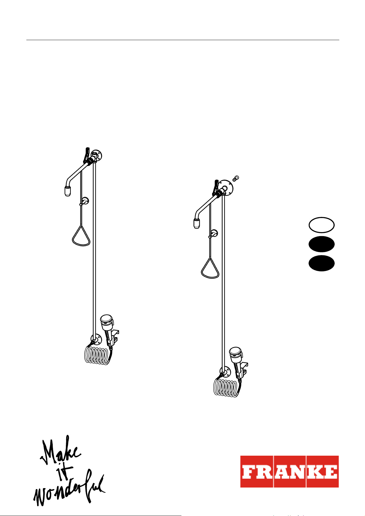
Emergency shower combination
Please refer to the graphics in the German installation and operating instructions.
0 Table of contents
1. Abbreviations and units . . . . . . . . . . . . . . . . . . . . . . . . . . . . . . . . 3
2. Key . . . . . . . . . . . . . . . . . . . . . . . . . . . . . . . . . . . . . . . . . . . . . . . . 3
3. Warranty . . . . . . . . . . . . . . . . . . . . . . . . . . . . . . . . . . . . . . . . . . . . 3
4. Important notes. . . . . . . . . . . . . . . . . . . . . . . . . . . . . . . . . . . . . . . 3
Description of product
5. Application . . . . . . . . . . . . . . . . . . . . . . . . . . . . . . . . . . . . . . . . . . 4
6. Technical specifications . . . . . . . . . . . . . . . . . . . . . . . . . . . . . . . . 4
7. Scope of delivery . . . . . . . . . . . . . . . . . . . . . . . . . . . . . . . . . . . . . 5
8. Dimensions. . . . . . . . . . . . . . . . . . . . . . . . . . . . . . . . . . . . . . . . . . 6
9. Installation example . . . . . . . . . . . . . . . . . . . . . . . . . . . . . . . . . . . 6
Assembly, function and commissioning
10. Installation of body shower water connection from above . . . . . . 7
11. Installation of body shower water connection from behind. . . . . . 11
12. Installation of eye shower . . . . . . . . . . . . . . . . . . . . . . . . . . . . . . . 16
13. Function . . . . . . . . . . . . . . . . . . . . . . . . . . . . . . . . . . . . . . . . . . . . 18
Maintenance
14. Maintenance and care . . . . . . . . . . . . . . . . . . . . . . . . . . . . . . . . . 19
15. Replacing a filter. . . . . . . . . . . . . . . . . . . . . . . . . . . . . . . . . . . . . . 19
16. Replacing the flow rate regulator . . . . . . . . . . . . . . . . . . . . . . . . . 20
17. Replacing the non-return valve. . . . . . . . . . . . . . . . . . . . . . . . . . . 21
18. Troubleshooting . . . . . . . . . . . . . . . . . . . . . . . . . . . . . . . . . . . . . . 21
19. Spare parts . . . . . . . . . . . . . . . . . . . . . . . . . . . . . . . . . . . . . . . . . . 22
1. Abbreviations and units
EA-Nr. European article number
FAR-Best.-Nr. Franke Aquarotter order number
Conversion 1 mm = 0.03937 inches
1 inch = 25.4 mm
All length specifications in the graphics are in mm.
ZMI_001_2030019212-FAID0010_#SEN_#AQU_#V1.fm
- 3 -
Page 4

2. Key
Warning!
Failure to observe can result in bodily injury or even death.
Caution!
Failure to observe can result in material damage.
☞ Important!
Failure to observe can cause the product to malfunction.
☞ Useful information for optimum handling of the product.
3. Warranty
Liability is accepted in accordance with the General Terms and Conditions of
Business and Supply.
Use only genuine spare parts!
4. Important notes
• Installation, commissioning and maintenance must be performed only by a
qualified expert in accordance with the instructions provided, legal requirements
and recognised engineering standards.
• All technical connection regulations specified by the local water and electricity
supply companies must be observed.
• We reserve the right to make changes.
5. Application
Emergency showers are prescribed first aid installations for work stations where
hazardous materials are being handled.
- 4 -
ZMI_001_2030019212-FAID0010_#SEN_#AQU_#V1.fm
Page 5

6. Technical specifications
Body shower
Minimum flow pressure: 0.5 bar
Maximum stagnation pressure: 10 bar
Volumetric flow:
0.5 bar flow pressure: 45 l/m
1.0 bar flow pressure: 65 l/m
1.5 bar flow pressure: 80 l/m
2.0 bar flow pressure: 90 l/m
2.5 bar flow pressure: 100 l/m
3.0 bar flow pressure: 110 l/m
Assembly height: Lower edge of shower head (220 ± 10) cm
above floor as per EN 15154 Part 1
Eye shower
Version: Hand shower plastic green/white
Wall mounting, tilted 20° forwards, spiral hose and
protective cap with user information
Minimum flow
pressure: 1 bar
Flow pressure range: 1-4 bar
This range meets the requirements of EN 15154.
Volumetric flow: Constant 6-9 l/s at a flow pressure of 1 bar
ZMI_001_2030019212-FAID0010_#SEN_#AQU_#V1.fm
- 5 -
Page 6

7. Scope of delivery
Pos. Name 2030019212 2030019221
1 Shower head x x
2 Wall bracket x x
3 Ball valve x x
4 Wall plate with connecting pipe x
5 Wall plate with connecting pipe and plug-in
socket
x
6 Hand actuator with plugging option x x
7 Accessories kit:
First aid sign, screws and wall plug
xx
8 Eye shower with safety cap x x
9 Wall mounting with attachment set x x
10 Spiral supply hose with filter x x
11 First aid sign x x
Installation and operating instructions x x
8. Dimensions
For special designs, see the customer drawing for dimensions
9. Installation example
10. Installation of body shower water connection from above
☞ Important!
• Prior to the assembly process, flush the pipework in accordance with DIN 1988.
• Mount the emergency shower in accordance with EN 15154 Part 1.
☞ The manual actuator of the emergency shower can be plugged.
☞ To protect the tiles, use masking tape when marking and drilling. Drill at low speed.
☞ Depending on the composition of the wall, special wall plugs may have to be used
(to be provided by the customer).
10.1
Screw the connecting pipe (b) into the wall plate (a) so that a seal is formed.
- 6 -
ZMI_001_2030019212-FAID0010_#SEN_#AQU_#V1.fm
Page 7

☞ Important!
Pay attention to precisely vertical alignment during installation.
10.2
Align the wall panel (a) 2310 ± 100 mm above the finished floor in accordance with
the water intake, and mark the drill holes.
10.3
Drill in accordance with these markings.
10.4
Insert the wall plugs.
10.5
Screw on the connecting pipe (b) with the wall plate (a).
10.6
Screw in the closed ball valve as far as possible, creating a seal and bringing it into
position as follows:
– The valve axis must point to
the left.
– The pivot motion of the valve lever must be aligned so that it is precisely
vertical.
10.7
Secure the ball valve (d) with the two grub screws (c).
10.8
Place the wall support (e) onto the guide (g) on the manual actuator and secure with
the grub screw (f).
10.9
Place the valve lever into the "close" position.
A: Closed
B: Open
10.10
Screw the manual actuator (j) into the fork head (h) of the deflection lever and lock
with a nut.
10.11
Using the spirit level, align the manual actuator (j) so that it is vertical.
10.12
Mark drill holes for the wall support (e) 40 mm above the triangular handle.
10.13
Drill in accordance with these markings.
10.14
Insert the wall plugs.
10.15
Screw on the wall support (e).
10.16
Screw the wall bracket (k) into the shower head (l) so that a seal is formed.
10.17
Seal in the shower head with the wall bracket and bring into position.
10.18
Establish the water connection.
10.19
Check the water connection for leaks.
ZMI_001_2030019212-FAID0010_#SEN_#AQU_#V1.fm
10.20
Plug the manual actuator if need be.
- 7 -
Page 8

11. Installation of body shower water connection from behind
☞ Important!
• Prior to the assembly process, flush the pipework in accordance with DIN 1988.
• Mount the emergency shower in accordance with EN 15154 Part 1.
☞ The manual actuator of the emergency shower can be plugged.
☞ To protect the tiles, use masking tape when marking and drilling. Drill at low speed.
☞ Depending on the composition of the wall, special wall plugs may have to be used
(to be provided by the customer).
11.1
Screw the connecting pipe (b) into the wall plate (a) so that a seal is formed.
☞ Important!
The internal thread G ¾ for the locally provided water connection may not protrude
from the wall by more than 1 mm, and may not extend into the wall by more than
15 mm.
11.2
Place the water connection centrally at a height of 2310 ± 100 mm above the
finished floor.
11.3
Screw in the plug-in socket (c) with an Allen key to form a seal.
☞ Important!
Pay attention to precisely vertical alignment during installation.
11.4
Slide the wall plate (a) onto the plug-in socket (c) and align it.
11.5
Mark the drill holes.
11.6
Drill in accordance with these markings.
11.7
Insert the wall plugs.
11.8
Slide the wall plate (a) onto the plug-in socket (c) as far as the wall and fix in place
with the grub screw (d).
11.9
Screw on the wall plate (a) and the connecting pipe (b).
11.10
Screw in the closed ball valve as far as possible, creating a seal and bringing it into
position as follows:
– The valve axis must point to
the left.
– The pivot motion of the valve lever must be aligned so that it is precisely
vertical.
11.11
Secure the ball valve (f) with the two grub screws (e).
11.12
Place the wall support (g) onto the guide (j) on the manual actuator and secure with
the grub screw (h).
11.13
Place the valve lever into the "close" position.
A: Closed
B: Open
- 8 -
ZMI_001_2030019212-FAID0010_#SEN_#AQU_#V1.fm
Page 9

11.14
Screw the manual actuator (l) into the fork head (h) of the deflection lever and lock
with a nut.
11.15
Using the spirit level, align the manual actuator (l) so that it is vertical.
11.16
Mark drill holes for the wall support (g) 40 mm above the triangular handle.
11.17
Drill in accordance with these markings.
11.18
Insert the wall plugs.
11.19
Screw on the wall support (g).
11.20
Screw the wall bracket (m) into the shower head (n) so that a seal is formed.
11.21
Seal in the shower head with the wall bracket and bring into position.
11.22
Establish the water connection.
11.23
Check the water connection for leaks.
11.24
Plug the manual actuator if need be.
12. Installation of eye shower
☞ Important!
• Prior to the assembly process, flush the pipework in accordance with DIN 1988.
• Mount the eye shower in accordance with EN 15154 Part 2.
12.1
Mount the wall bracket (b) to the extension (a).
12.2
Mark the drill holes for the wall bracket at a height (c) of 590 mm to 990 mm from the
upper edge of the finished floor.
12.3
Drill holes in accordance with these markings.
12.4
Insert the wall plugs.
12.5
Mount the extension (a).
Caution!
Note the installation position of the filter.
12.6
Insert the filter (b) into the hose (c).
12.7
Connect the eye shower (a) to the hose (c).
12.8
Insert the hose (c) into the wall bracket (e).
ZMI_001_2030019212-FAID0010_#SEN_#AQU_#V1.fm
12.9
The handle bar (d) must face forwards.
12.10
Screw the hose (c) onto the connection piece (f), using an open-ended wrench.
12.11
Check the water connection for leaks.
- 9 -
Page 10

13. Function
13.1
Pull the manual actuator.
• The water will flow.
☞ The valve is not self-closing!
13.2
Place the manual actuator back in its start position.
• The water stops flowing.
Stationary use
13.3
Press the trigger button.
• The water will flow.
• The safety cap will fall off.
13.4
Press the red stop button.
• The water flow will stop.
☞ The valve is not self-closing! The user can use both hands to keep their eyes open!
Mobile use
☞ Depending on the length of the hose, the eye shower can also be pulled out of its
bracket.
14. Maintenance and care
Check the emergency shower combination once a month to make sure that it is in
working order. (Guidelines for Laboratories BGI/GUV-I 850-0)
As a measure for the prevention of microbiological contamination, it is recommended that you replace the fill water in the fitting at shorter intervals by opening the
valve.
Use suitable cleaning agents which do not attack the tap in a proper manner and
rinse with water after use. High-pressure cleaners must not be used for cleaning.
15. Replacing a filter
15.1
Close the water supply.
15.2
Take the eye shower (a) out of the wall bracket.
15.3
Loosen the eye shower (a) from the hose (d).
15.4
Replace the (c) filter.
☞ Important!
Note the installation position of the filter.
☞ The handle bar (b) must face forwards.
15.5
Reassemble in reverse order.
ZMI_001_2030019212-FAID0010_#SEN_#AQU_#V1.fm
- 10 -
Page 11

16. Replacing the flow rate regulator
16.1
Interrupt the water supply.
16.2
Take the eye shower (a) out of the wall bracket.
16.3
Loosen the hose (b).
16.4
Use a bent wire to lift out the flow volume regulator and replace it.
Caution!
Note the installation position of the non-return valves.
☞ Do not forget the seal.
16.5
Reassemble in reverse order.
17. Replacing the non-return valve
Caution!
The non-return valve must be replaced every 2 years.
17.1
Loosen the screw (a).
17.2
Remove the shower base (b).
17.3
Remove the spray heads (c) and the seals (d).
17.4
Unscrew the attachment part (e).
17.5
Remove the disc (f).
17.6
Push out the non-return valve (g).
17.7
Reassemble in reverse order.
18. Troubleshooting
Fault Cause Remedy
Water does not flow – Water supply interrupted ➯ Restore it
Manual actuator is
catching
Body shower is
dripping
– Ball valve not correctly aligned ➯ Align it
– Pull rod or manual actuator bent ➯ Straighten it
– Ball valve stiff ➯ Replace it
– Ball valve defective ➯ Replace it
Water volume too low – Flow volume regulator faulty ➯ Replace it
– Dirty filter ➯ Clean it
If you cannot rectify a fault or if it is not in the list, please contact our customer
service department!
ZMI_001_2030019212-FAID0010_#SEN_#AQU_#V1.fm
- 11 -
Page 12

19. Spare parts
Description Order No.
1 Hand shower complete . . . . . . . . . . . 2000105863
2 Spray head (packaging unit 4x) . . . . 2000104725
3 Safety cap
with ball chain . . . . . . . . . . . . . . . 2000105849
4 Non-return valve
(packaging unit 10x) . . . . . . . . . . 2000104744
5 Spiral connection hose . . . . . . . . . . . 2000105844
6 Flow volume regulator . . . . . . . . . . . 2000105842
7 Filter (packaging unit 10x) . . . . . . . . 2000104732
Service kit consisting of:
O-rings. . . . . . . . . . . . . . . . . . . . . 2000105864
Ball valve . . . . . . . . . . . . . . . . . . . . . 2030025022
☞ Other spare parts on request; see the
wall bracket for material numbers.
ZMI_001_2030019212-FAID0010_#SEN_#AQU_#V1.fm
- 12 -
Page 13

0Polski
PL
Połączenie prysznica awaryjnego
Patrz rysunek w niemieckiej instrukcji montażu i obsługi.
0 Spis treści
1. Skróty i jednostki . . . . . . . . . . . . . . . . . . . . . . . . . . . . . . . . . . . . . 14
2. Objaśnienie symboli . . . . . . . . . . . . . . . . . . . . . . . . . . . . . . . . . . . 14
3. Gwarancja . . . . . . . . . . . . . . . . . . . . . . . . . . . . . . . . . . . . . . . . . . 14
4. Ważne uwagi . . . . . . . . . . . . . . . . . . . . . . . . . . . . . . . . . . . . . . . . 14
Opis produktu
5. Zastosowanie . . . . . . . . . . . . . . . . . . . . . . . . . . . . . . . . . . . . . . . . 14
6. Dane techniczne. . . . . . . . . . . . . . . . . . . . . . . . . . . . . . . . . . . . . . 15
7. Zakres dostawy . . . . . . . . . . . . . . . . . . . . . . . . . . . . . . . . . . . . . . 16
8. Wymiary . . . . . . . . . . . . . . . . . . . . . . . . . . . . . . . . . . . . . . . . . . . . 16
9. Przykład instalacji . . . . . . . . . . . . . . . . . . . . . . . . . . . . . . . . . . . . . 16
Montaż, działanie i uruchomienie
10. Montaż prysznica z przyłączem wody od góry . . . . . . . . . . . . . . . 16
11. Montaż prysznica z przyłączem wody od tyłu. . . . . . . . . . . . . . . . 18
12. Montaż prysznica do przemywania oczu . . . . . . . . . . . . . . . . . . . 19
13. Działanie. . . . . . . . . . . . . . . . . . . . . . . . . . . . . . . . . . . . . . . . . . . . 20
Konserwacja
14. Konserwacja i czyszczenie. . . . . . . . . . . . . . . . . . . . . . . . . . . . . . 20
15. Wymiana sitka . . . . . . . . . . . . . . . . . . . . . . . . . . . . . . . . . . . . . . . 20
16. Wymiana ogranicznika przepływu . . . . . . . . . . . . . . . . . . . . . . . . 21
17. Wymiana zaworu zwrotnego . . . . . . . . . . . . . . . . . . . . . . . . . . . . 21
18. Usuwanie usterek . . . . . . . . . . . . . . . . . . . . . . . . . . . . . . . . . . . . . 21
19. Części zamienne . . . . . . . . . . . . . . . . . . . . . . . . . . . . . . . . . . . . . 22
ZMI_001_2030019212-FAID0010_#SPL_#AQU_#V1.fm
- 13 -
Page 14

1. Skróty i jednostki
EA-Nr. Europejski numer artykułu
FAR-Best.-Nr. Nr katalogowy Franke Aquarotter
Przeliczanie jednostek 1 mm = 0,03937 cala
1 cal = 25,4 mm
Wszystkie długości na rysunkach podano w mm.
2. Objaśnienie symboli
Ostrzeżenie!
Nieprzestrzeganie może spowodować zagrożenie życia lub ryzyko urazu.
Uwaga!
Nieprzestrzeganie może spowodować szkody materialne.
☞ Ważne!
Nieprzestrzeganie może spowodować zakłócenia w działaniu produktu.
☞ Informacje przydatne do optymalnego obchodzenia się z produktem.
3. Gwarancja
Zakres odpowiedzialności producenta wynika z ogólnych warunków handlowych.
Używać wyłącznie oryginalnych części zamiennych!
4. Ważne uwagi
•Montaż, uruchamianie i konserwacja muszą być przeprowadzane przez specja-
listę zgodnie z dostarczoną instrukcją, przepisami prawnymi i ogólnie przyjętymi
normami technicznymi.
•Należy przestrzegać warunków technicznych wydanych przez lokalne zakłady
wodociągowe i energetyczne.
• Wszelkie zmiany zastrzeżone.
5. Zastosowanie
Prysznice bezpieczeństwa są urządzeniami pierwszej pomocy wymaganymi
w miejscach pracy, w których występują substancje niebezpieczne.
- 14 -
ZMI_001_2030019212-FAID0010_#SPL_#AQU_#V1.fm
Page 15

6. Dane techniczne
Prysznic
Minimalne ciśnienie przepływu: 0,5 bar
Maksymalne ciśnienie spoczynkowe: 10 bar
Przepływ:
ciśnienie przepływu 0,5 bar: 45 l/m
ciśnienie przepływu 1,0 bar: 65 l/m
ciśnienie przepływu 1,5 bar: 80 l/m
ciśnienie przepływu 2,0 bar: 90 l/m
ciśnienie przepływu 2,5 bar: 100 l/m
ciśnienie przepływu 3,0 bar: 110 l/m
Wysokość montażowa: Krawędź dolna głowicy natryskowej
(220 ± 10) cm nad podłogą zgodnie
z normą EN 15154 część 1
Prysznic do przemywania oczu
Wykonanie: Natrysk ręczny z tworzywa sztucznego, zielono-
biały, uchwyt ścienny, odchylony o 20° do przodu,
wąż spiralny i pokrywka ochronna z informacją dla
użytkownika
Minimalne ciśnienie
przepływu: 1 bar
Zakres ciśnienia
przepływu:
1-4 bar
W tym zakresie spełnione są wymagania normy
EN 15154.
Przepł
yw: 6-9 l/min stale przy ciśnieniu przepływu 1 bar
ZMI_001_2030019212-FAID0010_#SPL_#AQU_#V1.fm
- 15 -
Page 16

7. Zakres dostawy
Poz. Opis 2030019212 2030019221
1Głowica natryskowa x x
2 Wylewka x x
3 Zawór kulowy x x
4Płytka ścienna z rurą przyłączeniową x
5Płytka ścienna z rurą przyłączeniową i złączem x
6 Spust ręczny z możliwością plombowania x x
7 Dodatkowe opakowanie:
Znaki ewakuacyjne, śruby i kołki
8 Myjka do oczu z pokrywką ochronną xx
9Uchwyt ścienny z zestawem mocującym x x
10 Spiralny wąż podłączeniowy z sitkiem x x
11 Oznakowanie awaryjne x x
Instrukcja montażu i obsługi x x
xx
8. Wymiary
9. Przykład instalacji
10. Montaż prysznica z przyłączem wody od góry
☞ Ważne!
• Przed montażem należy przepłukać przewody rurowe zgodnie z normą DIN 1988.
•Zamontować prysznic bezpieczeństwa zgodnie z EN 15154, część 1.
☞ Spust ręczny prysznica awaryjnego może być zaplombowany.
☞ Przy trasowaniu i wierceniu otworów używać papierowej taśmy maskującej do
osłonięcia płytek. Wiercić z niewielką prędkością.
☞ W razie potrzeby użyć specjalistycznych kołków do różnych rodzajów ścian
(w zakresie klienta).
10.1
Szczelnie przykręcić rurę przyłączeniową (b) do płytki ściennej (a).
- 16 -
ZMI_001_2030019212-FAID0010_#SPL_#AQU_#V1.fm
Page 17

☞ Ważne!
Podczas montażu należy zapewnić dokładne wyrównanie pionowe.
10.2
Przystawić płytkę ścienną (a) do ściany na wysokości 2310 ± 100 mm nad podłogą,
odpowiednio do dopływu wody, i zaznaczyć otwory.
10.3
Wywiercić otwory zgodnie z zaznaczeniami.
10.4
Włożyć kołki.
10.5
Przykręcić rurę przyłączeniową (b) do płytki ściennej (a).
10.6
Zamknięty zawór kulowy wkręcić jak najdalej do końca i ustawić w następującym
położeniu:
–Oś zaworu powinna być skierowana w lewo.
– Ruch obrotowy dźwigni zaworu musi odbywać się dokładnie pionowo.
10.7
Unieruchomić zawór kulowy (d) dwoma wkrętami bez łba (c).
10.8
Nasunąć podporę ścienną (e) na prowadnicę (g) w spuście ręcznym
i unieruchomić kołkiem gwintowanym (f).
10.9
Dźwignię zaworu ustawić
w położeniu zamknięcia.
A: zamknięto
B: otwarto
10.10
Wkręcić spust ręczny (j) w widełki (h) dźwigni kierunkowej i zablokować go nakrętką.
10.11
Za pomocą poziomicy ustawić pionowo spust ręczny (j).
10.12
Na wysokości 40 mm nad trójkątną rączką zaznaczyć otwory do przykręcenia
podpory ściennej (e).
10.13
Wywiercić otwory zgodnie z zaznaczeniami.
10.14
Włożyć kołki.
10.15
Przykręcić podporę ścienną (e).
10.16
Wkręcić wylewkę (k) do oporu
w głowicę natryskową (l).
10.17
Uszczelnić głowicę natryskową
z wylewką i ustawić we właściwym położeniu.
10.18
Podłączyć wodę.
10.19
Sprawdzić szczelność przyłącza wody.
10.20
W razie konieczności zaplombować spust ręczny.
ZMI_001_2030019212-FAID0010_#SPL_#AQU_#V1.fm
- 17 -
Page 18

11. Montaż prysznica z przyłączem wody od tyłu
☞ Ważne!
• Przed montażem należy przepłukać przewody rurowe zgodnie z normą DIN 1988.
•Zamontować prysznic bezpieczeństwa zgodnie z EN 15154, część 1.
☞ Spust ręczny prysznica awaryjnego może być zaplombowany.
☞ Przy trasowaniu i wierceniu otworów używać papierowej taśmy maskującej do
osłonięcia płytek. Wiercić z niewielką prędkością.
☞ W razie potrzeby użyć specjalistycznych kołków do różnych rodzajów ścian
(w zakresie klienta).
11.1
Szczelnie przykręcić rurę przyłączeniową (b) do płytki ściennej (a).
☞ Ważne!
Przewidziane na budowie przyłącze wodne o gwincie wewnętrznym G ¾ nie
powinno wystawać więcej niż
1 mm ponad ścianę, a jego głębokość w ścianie nie powinna być większa niż 15
mm.
11.2
Wykonać przyłącze wody na wysokości 2310 ± 100 mm nad podłogą.
11.3
Za pomocą klucza imbusowego szczelnie dokręcić złącze (c).
☞ Ważne!
Podczas montażu należy zapewnić dokładne wyrównanie pionowe.
11.4
Wsunąć płytkę ścienną (a) na złącze (c) i wyrównać.
11.5
Zaznaczyć otwory.
11.6
Wywiercić otwory zgodnie z zaznaczeniami.
11.7
Włożyć kołki.
11.8
Wsunąć płytkę ścienną (a) na złącze (c) do ściany i przymocować ją kołkiem gwintowanym (d).
11.9
Przykręcić płytkę ścienną (a) i rurę przyłączeniową (b).
11.10
Zamknięty zawór kulowy wkręcić jak najdalej do końca i ustawić w następującym
położeniu:
–Oś zaworu powinna być skierowana w lewo.
– Ruch obrotowy dźwigni zaworu musi odbywać się dokładnie pionowo.
11.11
Unieruchomić zawór kulowy (f) dwoma wkrętami bez łba (e).
11.12
Nasunąć podporę ścienną (g) na prowadnicę (j) w spuście ręcznym
i unieruchomić kołkiem gwintowanym (h).
11.13
Dźwignię zaworu ustawić
w położeniu zamknięcia.
A: zamknięto
B: otwarto
- 18 -
ZMI_001_2030019212-FAID0010_#SPL_#AQU_#V1.fm
Page 19

11.14
Wkręcić spust ręczny (l) w widełki (h) dźwigni kierunkowej i zablokować go nakrętką.
11.15
Za pomocą poziomicy ustawić pionowo spust ręczny (l).
11.16
Na wysokości 40 mm nad trójkątną rączką zaznaczyć otwory do przykręcenia
podpory ściennej (g).
11.17
Wywiercić otwory zgodnie z zaznaczeniami.
11.18
Włożyć kołki.
11.19
Przykręcić podporę ścienną (g).
11.20
Wkręcić wylewkę (m) do oporu
w głowicę natryskową (n).
11.21
Uszczelnić głowicę natryskową
z wylewką i ustawić we właściwym położeniu.
11.22
Podłączyć wodę.
11.23
Sprawdzić szczelność przyłącza wody.
11.24
W razie konieczności zaplombować spust ręczny.
12. Montaż prysznica do przemywania oczu
☞ Ważne!
• Przed montażem należy przepłukać przewody rurowe zgodnie z normą DIN 1988.
•Zamontować myjkę do oczu zgodnie z EN 15154, część 2.
12.1
Zamontować podporę ścienną (b) na przedłużeniu (a).
12.2
Otwór uchwytu ściennego zaznaczyć na wysokości (c) od 590 mm do 990 mm od
powierzchni gotowej podłogi.
12.3
Wywiercić otwory zgodnie z zaznaczeniami.
12.4
Włożyć kołki.
12.5
Zdemontować przedłużenie (a).
Uwaga!
Pamiętać o prawidłowym położeniu montażowym sitka.
12.6
Włożyć sitko (b) do węża (c).
12.7
Połączyć prysznic do przemywania oczu (a) z wężem (c).
ZMI_001_2030019212-FAID0010_#SPL_#AQU_#V1.fm
12.8
Włożyć wąż (c) do podpory
ściennej (e).
12.9
Listwa z uchwytem (d) musi być skierowana do przodu.
12.10
Przykręcić wąż (c) do króćca podłączeniowego (f) przy pomocy klucza płaskiego.
12.11
Sprawdzić szczelność przyłącza wody.
- 19 -
Page 20

13. Działanie
13.1
Pociągnąć za spust ręczny.
• Woda wypływa.
☞ Bateria nie zamyka się samoczynnie!
13.2
Spust ręczny ustawić w położenie wyjściowe.
• Woda przestaje płynąć.
Korzystanie stacjonarne
13.3
Nacisnąć przycisk wyzwalający.
• Woda wypływa.
• Pokrywka ochronna spada.
13.4
Nacisnąć czerwony przycisk stop.
• Woda przestaje wypływać.
☞ Bateria nie zamyka się samoczynnie. Użytkownik może obiema rękami rozwierać
oczy!
Zastosowanie ruchome
☞ W zależności od długości węża, można wyciągnąć myjkę do oczu
z uchwytu.
14. Konserwacja i czyszczenie
Raz w miesiącu należy sprawdzać połączenie prysznica awaryjnego. (Wytyczne dla
laboratoriów BGI/GUV-I 850-0)
Jako działanie zapobiegawcze w celu uniknięcia skażenia mikrobiologicznego
zaleca się, aby w krótkich odstępach wymieniać wodę w baterii, otwierając zawór.
Używać odpowiednich środków czyszczących, niedziałających niszcząco na baterię.
Po użyciu spłukać wodą. Do czyszczenia nie używać myjek wysokociśnieniowych.
15. Wymiana sitka
15.1
Zamknąć dopływ wody.
15.2
Zdjąć prysznic do przemywania oczu (a) z podpory ściennej.
15.3
Odłączyć prysznic do przemywania oczu (a) od węża (d).
15.4
Wymienić sitko (c).
☞ Ważne!
Pamiętać o prawidłowym położeniu montażowym sitka.
☞ Listwa z uchwytem (b) musi być skierowana do przodu.
15.5
Montaż odbywa się w odwrotnej kolejności.
- 20 -
ZMI_001_2030019212-FAID0010_#SPL_#AQU_#V1.fm
Page 21

16. Wymiana ogranicznika przepływu
16.1
Odciąć dopływ wody.
16.2
Zdjąć prysznic do przemywania oczu (a) z podpory ściennej.
16.3
Odłączyć wąż (b).
16.4
Podważyć regulator przepływu wygiętym drutem i wymienić.
Uwaga!
Pamiętać o prawidłowym położeniu montażowym zaworów zwrotnych.
☞ Nie zapomnieć o uszczelce.
16.5
Montaż odbywa się w odwrotnej kolejności.
17. Wymiana zaworu zwrotnego
Uwaga!
Zawór przeciwzwrotny należy wymieniać co 2 lata.
17.1
Odkręcić śrubę (a).
17.2
Zdjąć kopułę dyszową (b).
17.3
Zdjąć głowice natryskowe (c) i uszczelki (d).
17.4
Wykręcić element mocujący (e).
17.5
Wyjąć podkładkę (f).
17.6
Wyciągnąć zawór zwrotny (g).
17.7
Montaż odbywa się w odwrotnej kolejności.
18. Usuwanie usterek
Usterka Przyczyna Środek zaradczy
Woda nie wypływa – Odcięty dopływ wody ➯ Przywrócić
Spust ręczny zacina
się
– Nierówno ustawiony zawór kulowy ➯ Wyrównać
– Wygięty drążek pociągowy wzgl.
spust ręczny
– Utrudnione działanie zaworu
kulowego
➯ Wyrównać
➯ Wymienić
Prysznic cieknie – Uszkodzony zawór kulowy ➯ Wymienić
Zbyt mały przepływ
wody
Każda usterka, której nie można samodzielnie usunąć lub nie została opisana
powyżej, powinna być zgłoszona naszemu działowi obsługi klienta!
ZMI_001_2030019212-FAID0010_#SPL_#AQU_#V1.fm
– Usterka regulatora przepływu ➯ Wymienić
– Zanieczyszczone sitko ➯ Wyczyścić
- 21 -
Page 22

19. Części zamienne
Nazwa Nr zam.
1 Natrysk ręczny kompletny . . . . . . . . . 2000105863
2Głowica natryskowa (4 szt. w opak.) . .2000104725
3 Pokrywka ochronna
z łańcuszkiem kulkowym. . . . . . . .2000105849
4 Zawór zwrotny
(10 szt. w opak.) . . . . . . . . . . . . . . 2000104744
5Spiralny wąż podłączeniowy . . . . . . .2000105844
6 Regulator przepływu . . . . . . . . . . . . . 2000105842
7 Sitko (10 szt. w opak.) . . . . . . . . . . . . 2000104732
Zestaw naprawczy zawiera:
Pierścienie o-ring . . . . . . . . . . . . .2000105864
Zawór kulowy . . . . . . . . . . . . . . . . . . 2030025022
☞ Pozostałe części zamienne na
zamówienie, nr art. zobacz wylewka.
ZMI_001_2030019212-FAID0010_#SPL_#AQU_#V1.fm
- 22 -
Page 23

Notes / Uwagi
ZMI_001_2030019212-FAID0010_#SPL_#AQU_#V1.fm
- 23 -
Page 24

Australia
PR Kitchen and Water Systems Pty Ltd
Dandenong South VIC 3175
Phone +61 3 9700 9100
Austria
Franke GmbH
6971 Hard
Phone +43 5574 6735 0
Belgium & Luxembourg
Franke N.V.
9400 Ninove, Belgium
Phone +32 54 310 130
Czech Republic
Franke Aquarotter GmbH
14974 Ludwigsfelde, Germany
Phone +420 281 090 429
France
Franke GmbH
6971 Hard, Austria
Phone +33 800 909 216
Germany
Franke Aquarotter GmbH
14974 Ludwigsfelde
Phone +49 3378 818 0
Italy
Franke Water Systems AG
4663 Aarburg, Switzerland
Numero Verde 800 789 233
Middle East
Franke LLC
Ras Al Khaimah, United Arab Emirates
Phone +971 7 2034 700
Morocco
Franke Kitchen System SARL
21 000 Casablanca
Phone +212 522 674 200
Netherlands
Franke N.V.
9400 Ninove, Belgium
Phone +31 492 72 82 24
Poland
Franke Aquarotter GmbH
14974 Ludwigsfelde, Germany
Phone +48 58 35 19 700
Portugal
Franke Portugal S.A.
2735-531 Cacém
Phone +351 21 426 9670
South Africa & Sub Saharan Africa
Franke South Africa
Durban, 4052
Phone + 27 31 450 6300
Spain
Franke GmbH
6971 Hard, Austria
Phone +43 5574 6735 211
Switzerland & Liechtenstein
Franke Water Systems AG
4663 Aarburg
Phone +41 62 787 3131
Tur key
Franke Mutfak ve Banyo Sistemleri
Sanayi ve Ticaret A.S.
41400 Gebze Kocaeli
Phone +90 262 644 6595
United Kingdom
Franke Sissons Ltd.
Barlborough S43 4PZ
Phone +44 1246 450 255
Dart Valley Systems Ltd.
Paignton TQ4 7TW
Phone +44 1803 529 021
EAST EUROPE
Bosnia Herzegovina | Bulgaria |
Croatia | Hungary | Latvia | Lithuania |
Romania | Russia | Serbia | Slovakia |
Slovenia | Ukraine
Franke Aquarotter GmbH
14974 Ludwigsfelde, Germany
Phone +49 3378 818 530
NORTH AMERICA
United States | Canada
Franke Kindred Canada Limited
Midland, ON L4R 4K9, Canada
Phone +1 855 446 5663
SCANDINAVIA & ESTONIA
Finland | Sweden | Norway |
Denmark | Estonia
Franke Finland Oy
76850 Naarajärvi, Finland
Phone +358 15 34 111
OTHER COUNTRIES
Franke GmbH
6971 Hard, Austria
Phone +43 5574 6735 0
www.franke.com
© Franke Technology and Trademark Ltd., Switzerland / 24.09.19 / 2030021428
 Loading...