

Page 1

F3D3 Dual and Single Lane Versions Frozen French
Fry Dispenser
Service Manual
Page 2

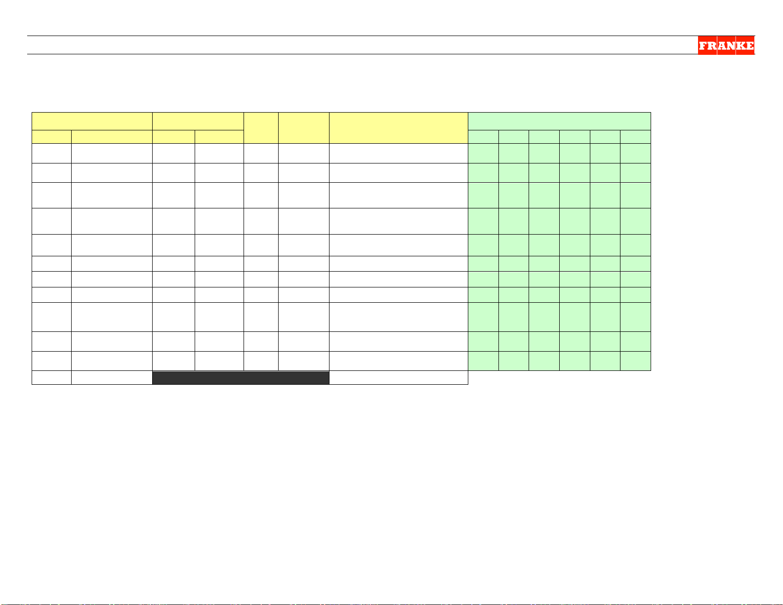
F3D3 Series Service Manual Table of Contents/Section 1.1
Section No. Content/Service Operation Issued/Updated
1.1 Table of Contents 11-13-12
1.1.1 Model Identification Guide 5-30-12
1.2.1 Franke Warranty Coverage 5-30-12
1.2.2 Franke Service Contact Information 5-30-12
1.3 F3D3 Series Trouble Shooting Guide 6-6-12
1.4 Display Error Message Guide 5-21-12
1.5 F3D3 Series Parts List & Component Diagrams
1.6 F3D3 Series Electric Schematics 5-24-12
1.7 Control P anel Quick-Guide 5-21-12
Setup, Diagnostic & Programming Instructions
1.8 Customer Level Access Instructions 5-30-12
1.9 Load Cell Calibration Instructions 5-30-12
1.10 Factory Level 1 Setup Access Instructions 5-30-12
1.11 Factory Level 3 Operating Parameter Access & Version Guide 11-13-12
1.11.1 Factory Level 3 Parameter Programming for BL 2.00 11-13-12
1.11.2 Factory Level 3 Parameter Prog r am ming for H47C1 11-13-12
1.11.3 Factory Level 3 Parameter Programming for H46P9 11-13-12
1.11.4 Factory Level 3 Display Menu for H46N ONLY 11-13-12
Part Replacement (See Section 4 for Refrigeration Repairs)
2.1 General Service Instructions, Warnings & Tools 5-24-12
2.2 Freezer Door Gasket Replacement 5-21-12
2.3 Automation Assemble [Complete] Replacement 5-22-12
2.4 Door Lift Slide Replacement 5-22-12
2.5 Drum Rotor Motor Replacement 5-22-12
2.6 Drum Rotor/Motor Block & Drive Shaft Replacement
2.7 Door Lift Motor Replacement 5-22-12
2.8 Door [Open] Motor Repl ace me nt 5-22-12
2.9 Product Door & Fi l l B uck et Ass e mbl y Replacement 5-22-12
2.10 Load Cell Replacement 5-30-12
2.11 Door-Closing Spring Replacement 5-22-12
2.12 Low Product Sensor Replacement 5-22-12
2.13 Basket Fill Plunger Switch Replacement 11-13-12
2.14 Door-Open Sensor R epl ace me nt 5-22-12
2.15 Touch Pad Controls Assembly Replacement 5-29-12
2.16 Main Power ON/OFF Switch Replacement 5-22-12
2.17 Temperature Controller Sensor Cable Replacement 5-22-12
2.18 24-Volt Power Supply Replacement 5-22-12
2.19 Compressor Relay Replacement (DIN Mounted) 5-22-12
2.20 Main PC Control Boar d Replacement 5-30-12
Questions? Call Franke Technical Support Group For Your Area. Page 1 Copyright 2012 Franke, Inc. All rights reserved.
Page 3

F3D3 Series Service Manual Table of Contents/Section 1.1
Section No. Content/Service Operation Issued/Updated
Part Replacement...Continued
2.21 Main Control Board Chip Replacement 5-29-12
2.22 Door Frame & Freezer Bottom Heater Replacement 5-23-12
2.23 Power Cord Replacement 5-23-12
2.24 Hopper Rotor Replacement 5-23-12
Part or Component Adjustments
3.1 Low Product Sensor Sensitivity Adjustment 5-23-12
3.2 Reverse Door Hinges/Door Swing 5-23-12
3.3 Adjusting Automation Assembly Alignment 5-23-12
3.4 Drum Rotor Motor Adjustment [When making noises] 5-23-12
3.5 Fry Hopper Hanger Alignment 5-23-12
3.6 Activate Backup Temp. Display – Two Lane Models ONLY 5-23-12
Refrigeration System Repair & Replacement
4.0 Propane Refrigeration System SERVICE RESTRICTION 5-23-12
4.1 Basic [Operator] Refrigerator Maintenance 5-23-12
4.2 Replace Condenser F an Mot or 5-24-12
4.3 Replace Start Relay & Replace Start Capacitor 5-24-12
4.4 Check System Pressure & Electronic Leak Detection 5-24-12
4.4.1 Checking for Leaks with Nitrogen Pressure 11-13-12
4.4.2 Cold Wall Evaporator Leak Detection 11-13-12
4.5 Repair Sy stem [R e fri g er ant] Leak 5-24-12
4.6 Replace Thermostatic Expansion Valve & Filter 5-24-12
4.7 Condenser Unit Replacement 5-24-12
Service Bulletins
none
Rev. 2 11-13-12
Questions? Call Franke Technical Support Group For Your Area. Page 2 Copyright 2012 Franke, Inc. All rights reserved.
Page 4
F3D3 Series Service Manual Model Identification 1.1.1
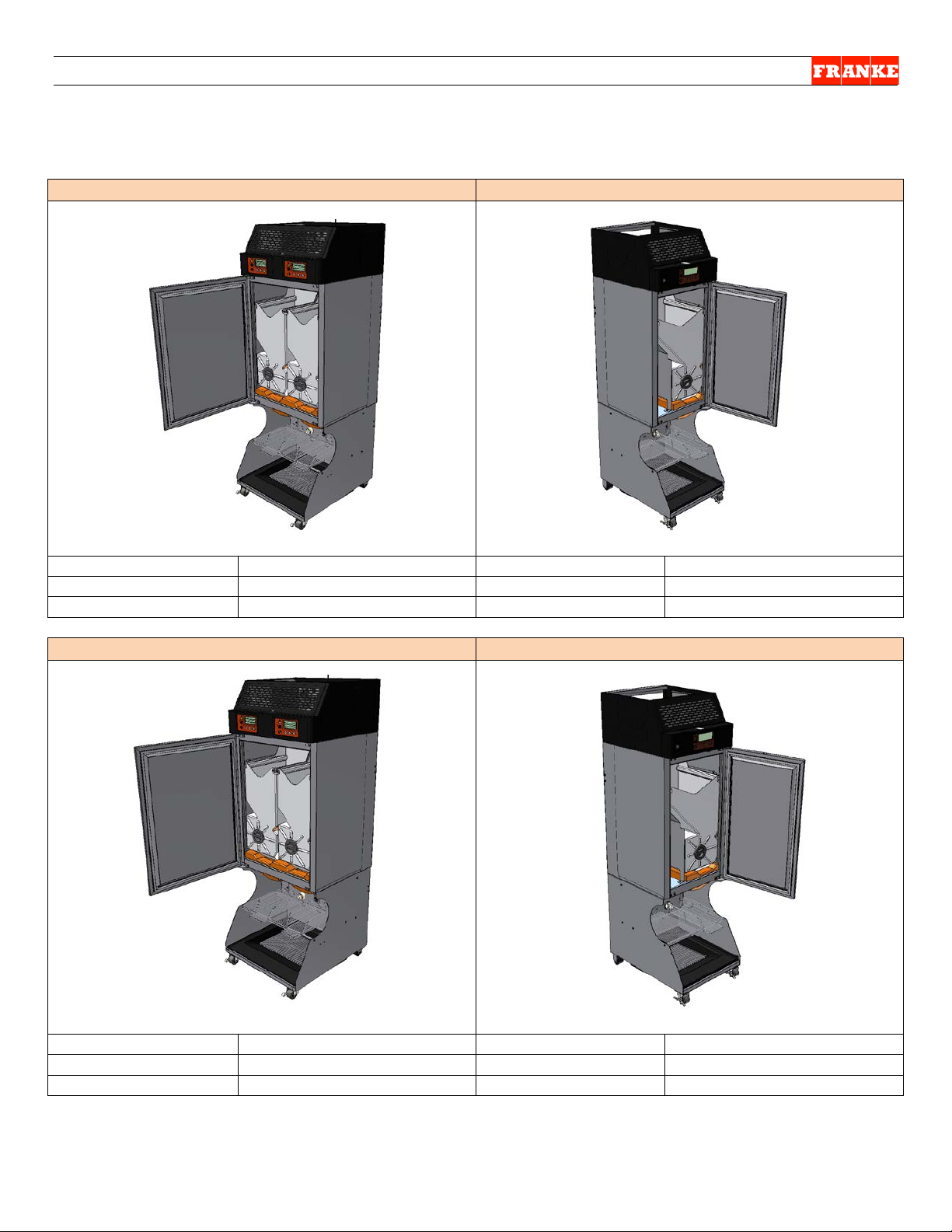
Model F3D3
Model F3D3S
Lanes & Controls:
Two Lanes
Lanes & Controls:
Single Lane
Unit Width:
711 mm (28”)
Unit Width:
559 mm (22”)
Refrigerant Type
R-404A
Refrigerant Type
R-404A
Model F3D3P
Model F3D3SP
Lanes & Controls:
Two Lanes
Lanes & Controls:
Single Lane
Unit Width:
711 mm (28”)
Unit Width:
559 mm (22”)
Refrigerant Type
R-290 PROPANE
Refrigerant Type
R-290 PROPANE
Model Identification Guide
(Shown Hinged-Left)
(Shown Hinged-Right)
(Shown Hinged-Left)
(Shown Hinged-Right)
Questions? Call Franke Technical Support Group For Your Area. Copyright 2012 Franke, Inc. All rights reserved.
Page 5
F3D3 Series Service Manual Factory Level 1 Setup Access / 1.10
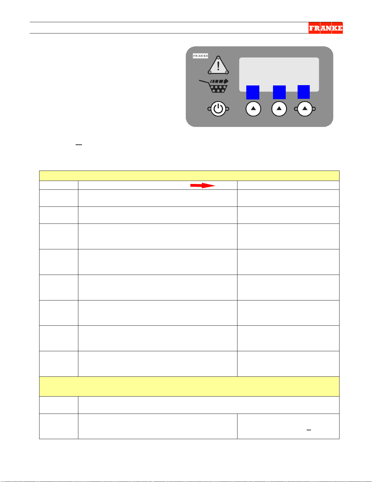
To Access Factory Level 1 Setup Parameters:
Step
Action Required
Resulting Display
1
From Standby condition use 3rd touchpad to
enter: 3 3 3 3. [The Entry Code]
Special Mode Select
Cust Fact Exit
2
Press touchpad 2 = Fact(ory)
Factory Access Level
Lev1 Lev3 Exit
Press touchpad 1 = Lev1
Low Level Reset ?
Yes No Exit
4
Press touchpad 1 = Yes
Setup = US
Inc Dec Exit
Press touchpad 1 = Inc [to scroll through]:
to go back up list.]
Setup = Europe or
Inc Dec OK
When you press touchpad 3 = OK, screen
* Setting Country *
* Specific Params * then:
Setup Complete
Config = US [setup chosen] then:
Calibrate Menu
OK Exit
7A or
Press touchpad 3 = Exit
Shut [appears then screen
goes blank]
Press touchpad 1 = OK [to initiate calibration]
Calibrate Menu
OK Exit
8
Press touchpad 1 = OK
NOTE: See SM Section LCC
NOTE: All programming is done using the
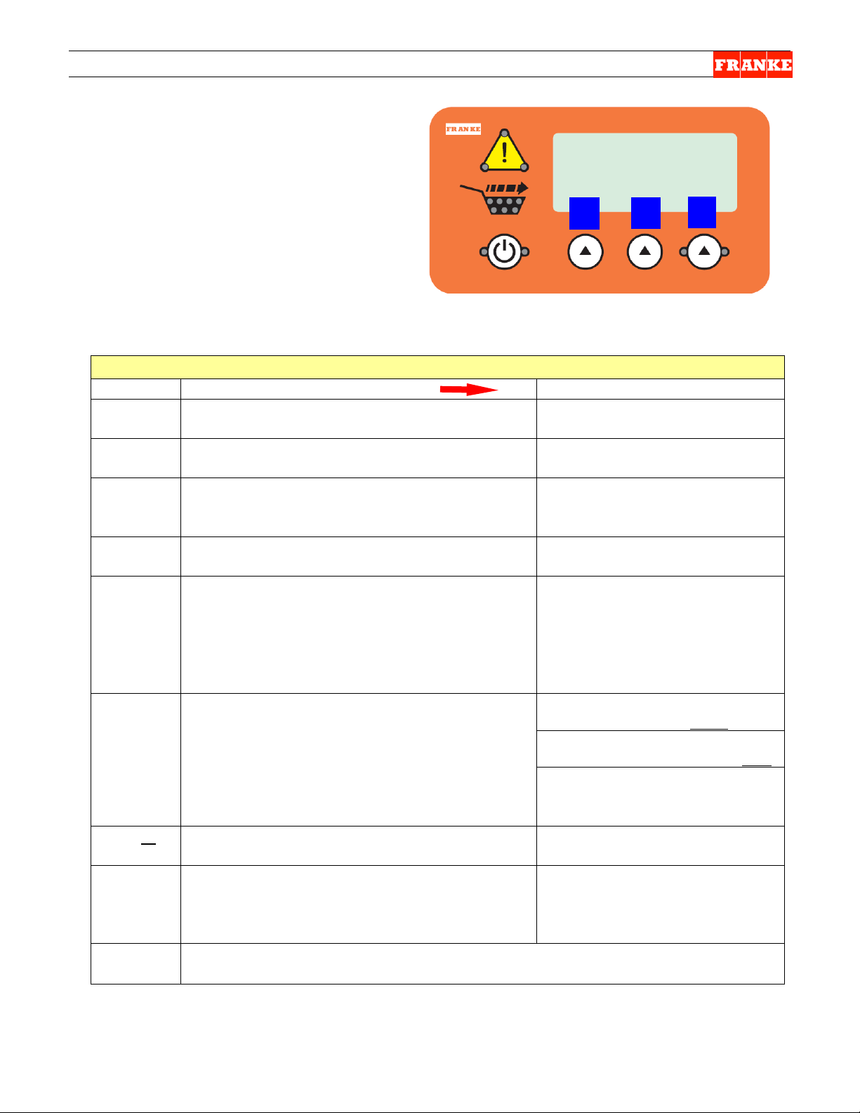
1
2
3
Setup Access & Resetting
F3D3 Series Fries Dispensers have easy
access to Factory-Level (1) setup and
resetting, using the lane operator interface
touch panel & display. To access:
1) Leave unit plugged in.
2) Turn Main Power Switch ON.
3) Lane power must be OFF. Display will
show current freezer temperature.
three choice buttons labeled: 1, 2 and 3 above.
3
5
6
7B
Press touchpad 2 = Dec [to go back up list]:
NOTE: If you press 1 = Inc on Setup =
APMEA, nothing changes. [Press 2 = Dec -
goes to:
Restores all NUM [numbers]
[or actual setup]
Setup = Japan or
Setup = Latin AM
[America] or
Setup = Canada or
Setup = APMEA
Begin ?
Loadcell = 00XX [Tar Value]
All Clear ?
Questions? Call Franke Technical Support Group For Your Area. Copyright 2012Franke, Inc. All rights reserved.
for Load Cell Calibration Ins tr uctions.
Rev. 1 6/2012
Page 6
F3D3 Series Service Manual Factory Level 3 Parameter Access / 1.11
For To Access Factory Level 3 Parameters:
Step
Action Required
Resulting Display
1
From Standby condition use 3rd touchpad to enter: 3
3 3 3. [The Entry Code]
Special Mode Select
Cust Fact Exit
2
Press touchpad 2 = Fact(ory)
Factory Access Level
Press touchpad 2 = Lev3
Password ??
Inc OK Exit
Press touchpad 2 = OK [Icon will move right to next
Password ??
Inc OK Exit
Press touchpad 2 = OK [Icon will move right to next
Password ??
Inc OK Exit
Press touchpad 2 = OK [Icon will move right to last
Password ??
Inc OK Exit
Press touchpad 1 = Inc once, to raise to 1, then:
Password ??
Inc OK Exit
Press touchpad 2 = OK
Language [first Parameter]
++ -- ->
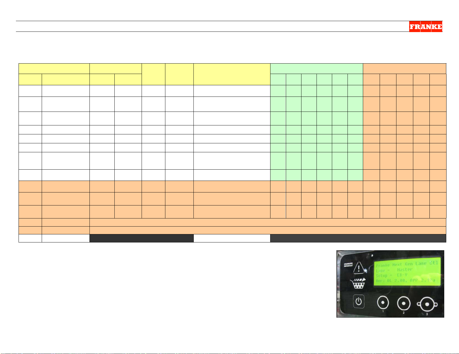
Software Version BL 2.00; APP 2.12a
On Lane Display
Parameter Table 1.11.1
Software Version: H47C1
On Chip Label*
Parameter Table 1.11.2
Software Version: H46P9
On Chip Label*
Parameter Table 1.11.3
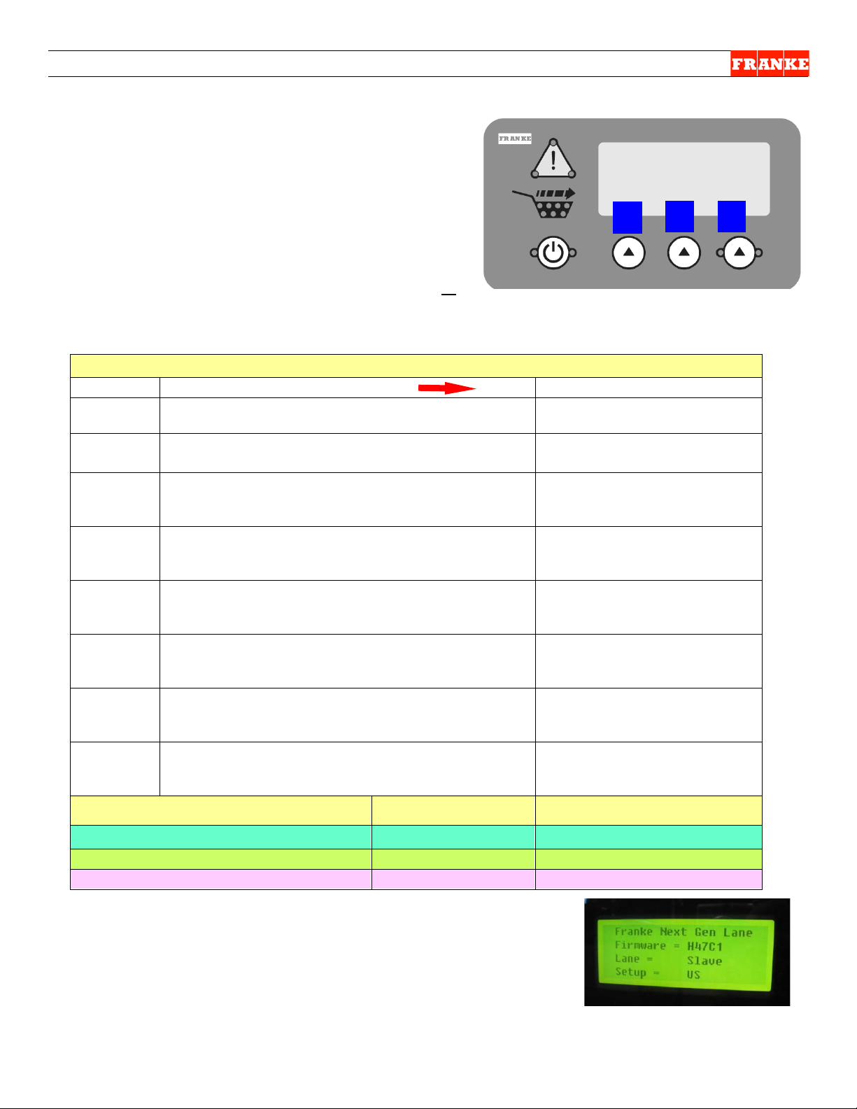
NOTE: All programming is done using the three
1
3
Parameter Access & Software Version
F3D3 Series Fries Dispensers provide easy access to
Factory Level operating and service diagnostic
parameters using the front operator interface touch
panel & display. To access:
1) Leave unit plugged in.
2) Turn Main Power Switch ON*.
3) Lane power must be OFF. Display will be blank or
show current freezer temperature, depending on
the model and lane.
choice buttons labeled: 1, 2 and 3 above.
Lev1 Lev3 Exit
2
3
4A
4B
4C
digit]
digit]
digit], then :
4D
5
For F3D3 Software Versi on To ID Version: Use Table:
∗ NOTE: The chip version is also displayed briefly during the
startup sequence ( a fter Calibration Valu es) , when the Main
POWER-ON switch is first turned ON. It appears as: Firmware =
H47C1, etc. on the second line.
Rev. 1 11/2012
Enter Password 0 _ _ _
Enter Password 0 0 _ _
Enter Password 0 0 0 _
Enter Password 0 0 0 0
Enter Password 0 0 0 1
P01 = English
Questions? Call Franke Technical Support Group For Your Area. Copyright 2012 Franke, Inc. All rights reserved.
Page 7

F3D3 Series Service Manual - Factory Lev3 Parameter Access / 1.11.1
To Access Factory Level 3 Parameters:
Step
Action Required
Resulting Display
1
From Standby condition use 3rd touchpad to
enter: 3 3 3 3. [The Entry Code]
Special Mode Select
Cust Fact Exit
2
Press touchpad 2 = Fact(ory)
Factory Access Level
Lev1 Lev3 Exit
Press touchpad 2 = Lev3
Password ??
Inc OK Exit
Press touchpad 2 = OK [Icon will move right to
Password ??
Inc OK Exit
Press touchpad 2 = OK [Icon will move right to
Password ??
Inc OK Exit
Press touchpad 2 = OK [Icon will move right to
Password ??
Inc OK Exit
Press touchpad 1 = Inc once, to raise to 1,
Password ??
Inc OK Exit
Press touchpad 2 = OK
Language [first Parameter]
++ -- ->
See Parameter Spreadsheet for P-numbers, functions & default settings.
NOTE Software Codes and exceptions that apply.
Notes:
Command Key: ++ to scroll up; -- to scroll down; -> to move flashing
underscore __ under next value; == to accept or OK value or setting
P02
Example:
Press 1 = ++ to increase temp. value [-0004]
Press 3 = == to accept (new) setting
Set Point [Refrig er at or t em p.]
++ -- ==
NOTE: All programming is done using the
1
2
3
Parameter Access & Programming
F3D3 Series Fries Dispensers provide easy
access to Factory Level operating and
service diagnostic parameters using the
front operator interface touch panel &
display. To access:
1) Leave unit plugged in.
2) Turn Main Power Switch ON.
3) Lane power must be OFF. Display will
be blank or show current freezer
temperature, depending on the lane.
three choice buttons labeled: 1, 2 and 3 above.
3
4A
4B
4C
4D
5
next digit]
next digit]
last digit], then:
then:
Enter Password 0 _ _ _
Enter Password 0 0 _ _
Enter Password 0 0 0 _
Enter Password 0 0 0 0
Enter Password 0 0 0 1
P01 = English
Set Point
Questions? Call Franke Technical Support Group For Your Area. Copyright 2012 Franke, Inc. All rights reserved.
Press 2 = -- to decrease temp. value [- 0006 ]
P02 = -0005 F
Rev. 1 6/2012
Page 8

F3D3 Series Service Manual Factory Level 3 Parameter Access / 1.11.1
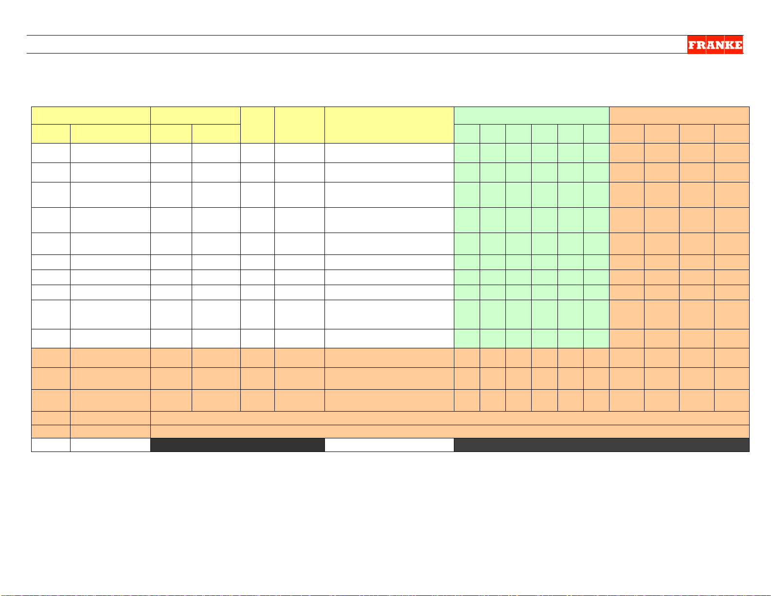
Parameter
Range
Unit3)
Default
Notes
Country Exceptions
No.
Name
Low
High
US
EU
JP
LA
CN
AP
EU-B
US-
GM
CAN-
GM
Other
-GM
EU-Y
P01
Language
1 5
1
1=English, 2=Deutsch,
5=French/English (Canada)
1 1 1 1 5 1 1 1 5 1 1
P02
Set Point
-50
20
Deg F
-5
Temperature set point
P03
Offset
P04
Point
-100
50
Deg F
40
alarm (LON Models only)
P05
High Alarm (Start
Up) Delay
1
300
minutes
100
signal, until message appears
P06
High Alarm Dwell
1
300
minutes
60
Temperature must remain (dwell)
for this time
P07
Hysteresis
0.5 5 Deg F
1.0
Used in temperature control
P09
Time
1
200
seconds
120
must be off before restarting.
P10
Down Shift LM
1
20=off
minutes
4
large to medium. 20 = Off
4 7 4 4 4 4 Off
Off
Off
Off
10
P11
Down Shift M1S
1
(20= off)
minutes
20 (off)
from medium to small. 20 = Off
Off 3 Off
Off
Off
Off
Off
Off
Off
Off
5
Off 7 Off
Off
Off
Off
Off
Off
Off
Off
10
P13
Thres(hold)
10
1500 750
counts/amp of motor current.
P14
Thres(hold)
10
1500 750
counts/amp of motor current.
Lift (Motor)
P16
Basket In Time
10
1500
mS
150
to trigger a dispense cycle
150
350
150
150
150
150
150
150
150
150
150
Factory Level 3 - Parameter Guide – Page 1
[For Latest Models with BL 2.00; APP 2.12a Chip Software1)]
Factory
3=Espanola, 4=Francais,
-30 30 Deg F 8 Temperature offset from sensor
High Alarm Set
Temperature that triggers a high
GM Exceptions
P12
P15
Compressor Off
Down Shift M2S
Drum (Motor)
Torq(ue)
Door (Motor)
Torq(ue)
Torq(ue)
Thres(hold)
(M)
(M)
(S)
19
19
1
10 1500 750
19
(20= off)
(M)
(M )
(M)
minutes 20 (off)
Time to wait after high alarm
Minimum time the compressor
Time for a size downshift from
Time for an initial size downshift
Time for subsequent size
downshift from medium to small.
20 = Off
Motor stops if threshold
exceeded. Approx 250
Motor stops if threshold
exceeded. Approx 250
Motor stops if threshold
exceeded. Approx 250
counts/motor current.
Time the basket must remain in
NOTES: 1) No Main Board Chip Label. Software Vers(ion): BL 2.00; APP 2.12a appears on Lane Display.
Questions? Call Franke Technical Support Group For Your Area. Copyright 2012 Franke, Inc. All rights reserved.
Page 9

F3D3 Series Service Manual Factory Level 3 Parameter Access / 1.11.1
Range
Unit3)
Default
Notes
Country Exceptions2)
No.
Name
Low
High
US
EU
JP
LA
CN
AP
EU-B
GM
GM
-GM
EU-Y
P17
Basket Out Time
10
1500
mS
50
out before enabling dispense
P18
Enable
Off
On On
being displayed.
P19
Enable
Off
On Off
slower) dispense for Japan.
Off
Off
On
Off
Off
Off
Off
Off
Off
Off
Off
P21
Large Fill Pct
P22
Medium Fill Pct
50
100
%
89
Reserved - Do not adjust.
P26
Toggle Rate
1 4
3
2 = Slow, 3 = Med, 4 = Fast)
P27
Display Units
C F
F
Temperature Display Units
Celsius or Fahrenheit
F C C C C C C F C
C
C
P28
Backdoor Type
English
Numeric
English
Displays numeric codes with
English or numeric codes only
Medium (Load)
75
P30
Factor
25
100 % 50
of large load
50
50
50
50
50
50
67
50
50
50
34
P31
Part Number
15 characters maximum. 1st must be 0-9 or F. 2nd must be 0-9, S, ‘.’ or ‘-‘. All others: 0-9, ‘-‘ or ‘.’
P32
Serial Number
P99
Factory Level 3 - Parameter Guide – Page 2
[For Latest Models with BL 2.00; APP 2.12a Chip Software1)]
Factory
Time the basket must remain
GM Exceptions
US-
CAN-
Other
P23
P29
Low Product
Hi Accuracy
Small Fill Pct
Dual Language
Factor
Small (Load)
Exit
50 100 % 90 Reserved - Do not adjust.
50 100 % 88 Reserved - Do not adjust.
25 100 % 67
15 characters maximum. All characters: 0-9 or ‘-‘
Prevents Low Product Warning
Enables high accuracy (but
If Dual Language is enabled,
this sets toggle rate: (1 = Off,
Weight of medium load as
percent of large load
Weight of small load as percent
Exits Level 3, if Entered
67 67 67 67 67 67 80 67 67 67
NOTES: 1) No Main Board Chip Label. Software Vers(ion): BL 2.00; APP 2.12a appears on Lane
Display. [How is this called up?]
2) Country Exceptions Abbreviations: US = North America; EU = Europe; JP = Japan; LA = Latin
America (South & Central); CN = Canada; AP = Asia, Pacific, Middle East & Australia
3) Unit Abbreviation: mS = Milliseconds
Questions? Call Franke Technical Support Group For Your Area. Copyright 2012 Franke, Inc. All rights reserved.
Page 10

F3D3 Series Service Manual - Factory Lev3 Parameter Access / 1.11.2
To Access Factory Level 3 Parameters:
Step
Action Required
Resulting Display
1
From Standby condition use 3rd touchpad to
enter: 3 3 3 3. [The Entry Code]
Special Mode Select
Cust Fact Exit
2
Press touchpad 2 = Fact(ory)
Factory Access Level
Lev1 Lev3 Exit
Press touchpad 2 = Lev3
Password ??
Inc OK Exit
Press touchpad 2 = OK [Icon will move right to
Password ??
Inc OK Exit
Press touchpad 2 = OK [Icon will move right to
Password ??
Inc OK Exit
Press touchpad 2 = OK [Icon will move right to
Password ??
Inc OK Exit
Press touchpad 1 = Inc once, to raise to 1,
Password ??
Inc OK Exit
Press touchpad 2 = OK
Language [first Parameter]
++ -- ->
See Parameter Spreadsheet for P-numbers, functions & default settings.
NOTE Software Codes and exceptions that apply.
Notes:
Command Key: ++ to scroll up; -- to scroll down; -> to move flashing
underscore __ under next value; == to accept or OK value or setting
P02
Example:
Press 1 = ++ to increase temp. value [-0004]
Press 3 = == to accept (new) setting
Set Point [Refrig er at or t em p.]
++ -- ==
NOTE: All programming is done using the
1
2
3
Parameter Access & Programming
F3D3 Series Fries Dispensers provide easy
access to Factory Level operating and
service diagnostic parameters using the
front operator interface touch panel &
display. To access:
1) Leave unit plugged in.
2) Turn Main Power Switch ON.
3) Lane power must be OFF. Display will
be blank or show current freezer
temperature, depending on the lane.
three choice buttons labeled: 1, 2 and 3 above.
3
4A
4B
4C
4D
5
next digit]
next digit]
last digit], then:
then:
Enter Password 0 _ _ _
Enter Password 0 0 _ _
Enter Password 0 0 0 _
Enter Password 0 0 0 0
Enter Password 0 0 0 1
P01 = English
Set Point
Questions? Call Franke Technical Support Group For Your Area. Copyright 2012 Franke, Inc. All rights reserved.
Press 2 = -- to decrease temp. value [- 0006 ]
P02 = -0005 F
Rev. 1 11/2012
Page 11

F3D3 Series Service Manual Factory Level 3 Parameter Access / 1.11.2
Parameter
Range
Unit3)
Default
Notes
Country Exceptions
No.
Name
Low
High
US
EU
JP
LA
CN
AP
EU-B
US-GM
CAN-
GM
Other-
GM
P01
Language
1 5
1
1=English, 2=Deutsch,
5=French/English (Canada)
1 1 1 1 5 1 1 1 5
1
P02
Set Point
-50
20
Deg F
-5
Temperature set point
P03
Offset
P04
Point
-100
50
Deg F
40
alarm (LON Models only)
P05
High Alarm (Sta r t
Up) Delay
1
300
minutes
100
signal, until message appears
P06
High Alarm Dwell
1
300
minutes
60
Temperature must remain (dwell)
for this time
P07
Hysteresis
0.5 5 Deg F
1.0
Used in temperature control
P08
Ticks / Sec
1
100 60
keeping.
P09
Time
1
200
seconds
120
must be off before restarting.
P10
Down Shift LM
1
20=off
minutes
4
large to medium. 20 = Off
4 7 4 4 4 4 20
20
20
20
P11
Down Shift M1S
1
(20= off)
minutes
20 (off)
from medium to small. 20 = Off
20 3 20
20
20
20
20
20
20
20
P12
Down Shift M2S
1
(20= off)
minutes
20 (off)
20 = Off
20 7 20
20
20
20
20
20
20
20
P13
Thres(hold)
10
1500 750
counts/amp of motor current.
P14
Thres(hold)
10
1500 750
counts/amp of motor current.
P15
Lift (Motor)
Thres(hold)
10
1500 750
counts/motor current.
Factory Level 3 - Parameter Guide – Page 1
[For Models with firmware version F3D3 Main H47C1 ONLY
Factory
3=Espanola, 4=Francais,
-30 30 Deg F 8 Temperature offset from sensor
High Alarm Set
Temperature that triggers a high
1)
]
GM Exceptions
Compressor Off
Drum (Motor)
Torq(ue)
Door (Motor)
Torq(ue)
Torq(ue)
19
19
19
(M)
(M)
(S)
(M)
(M )
(M)
Time to wait after high alarm
Used to correct onboard time
Minimum time the compressor
Time for a size downshift from
Time for an initial size downshift
Time for subsequent size
downshift from medium to small.
Motor stops if threshold
exceeded. Approx 250
Motor stops if threshold
exceeded. Approx 250
Motor stops if threshold
exceeded. Approx 250
NOTES: 1) Software version is printed on label on Main Control Board Chip.
Questions? Call Franke Technical Support Group For Your Area. Copyright 2012 Franke, Inc. All rights reserved.
Page 12
F3D3 Series Service Manual Factory Level 3 Parameter Access / 1.11.2
Range
Unit3)
Default
Notes
Country Exceptions2)
No.
Name
Low
High
US
EU
JP
LA
CN
AP
EU-B
US-GM
GM
GM
P16
Basket In Time
10
1500
mS
150
to trigger a dispense cycle
150
350
150
150
150
150
150
150
150
150
P17
Basket Out Time
P18
Enable
Enable
Off
On Off
slower) dispense for Japan.
Off
Off
On
Off
Off
Off
Off
Off
Off
Off
P20
Enable
Off
On Off
calibration. (Off or On)
P21
Large Fill Pct
P22
Medium Fill Pct
50
100
%
89
Reserved - Do not adjust.
Small Fill Pct
50
100 % 88
Reserved - Do not adjust.
P26
Toggle Rate
1 4
3
2 = Slow, 3 = Med, 4 = Fast)
P27
Display Units
C F
F
Temperature Display Units
Celsius or Fahrenheit
F C C C C C C F C
C
P28
Backdoor Type
English
Numeric
English
Displays numeric codes with
English or numeric codes only
P29
Medium (Load)
Factor
67
67
67
67
67
67
80
67
67
67
P30
Factor
25
100 % 50
of large load
50
50
50
50
50
50
67
50
50
50
P31
Part Number
15 characters maximum. 1st must be 0-9 or F. 2nd must be 0-9, S, ‘.’ or ‘-‘. All others: 0-9, ‘-‘ or ‘.’
P32
Serial Number
15 characters maximum. All character s : 0-9 or ‘-‘
Exits Level 3, if Entered
P19
P23
Low Product
Hi Accuracy
Large Load
Dual Language
Factory Level 3 - Parameter Guide – Page 2
[For Models with firmware version F3D3 Main H47C1 ONLY
Factory
Time the basket must remain in
10 1500 mS 50
Off On On
50 100 % 90 Reserved - Do not adjust.
Time the basket must remain
out before enabling dispense
Prevents Low Product Warning
being displayed.
Enables high accuracy (but
Enables use of 1Kg load for
If Dual Language is enabled,
this sets toggle rate: (1 = Off,
1)
]
GM Exceptions
CAN-
Other-
Weight of medium load as
percent of large load
Weight of small load as percent
P99
Small (Load)
Exit
25 100 % 67
NOTES: 1) Software version is printed on label on Main Control Board Chip.
2) Country Exceptions Abbreviations: US = North America; EU = Europe; JP = Japan; LA = Latin
America (South & Central); CN = Canada; AP = Asia, Pacific, Middle East & Australia
3) Unit Abbreviation: mS = Milliseconds
Questions? Call Franke Technical Support Group For Your Area. Copyright 2012 Franke, Inc. All rights reserved.
Page 13

F3D3 Series Service Manual - Factory Lev3 Parameter Access / 1.11.3
To Access Factory Level 3 Parameters:
Step
Action Required
Resulting Display
1
From Standby condition use 3rd touchpad to
enter: 3 3 3 3. [The Entry Code]
Special Mode Select
Cust Fact Exit
2
Press touchpad 2 = Fact(ory)
Factory Access Level
Lev1 Lev3 Exit
Press touchpad 2 = Lev3
Password ??
Inc OK Exit
Press touchpad 2 = OK [Icon will move right to
Password ??
Inc OK Exit
Press touchpad 2 = OK [Icon will move right to
Password ??
Inc OK Exit
Press touchpad 2 = OK [Icon will move right to
Password ??
Inc OK Exit
Press touchpad 1 = Inc once, to raise to 1,
Password ??
Inc OK Exit
Press touchpad 2 = OK
Language [first Parameter]
++ -- ->
See Parameter Spreadsheet for P-numbers, functions & default settings.
NOTE Software Codes and exceptions that apply.
Notes:
Command Key: ++ to scroll up; -- to scroll down; -> to move flashing
underscore __ under next value; == to accept or OK value or setting
P02
Example:
Press 1 = ++ to increase temp. value [-0004]
Press 3 = == to accept (new) setting
Set Point [Refrig er at or t em p.]
++ -- ==
NOTE: All programming is done using the
1
2
3
Parameter Access & Programming
F3D3 Series Fries Dispensers provide easy
access to Factory Level operating and
service diagnostic parameters using the
front operator interface touch panel &
display. To access:
1) Leave unit plugged in.
2) Turn Main Power Switch ON.
3) Lane power must be OFF. Display will
be blank or show current freezer
temperature, depending on the lane.
three choice buttons labeled: 1, 2 and 3 above.
3
4A
4B
4C
4D
5
next digit]
next digit]
last digit], then:
then:
Enter Password 0 _ _ _
Enter Password 0 0 _ _
Enter Password 0 0 0 _
Enter Password 0 0 0 0
Enter Password 0 0 0 1
P01 = English
Set Point
Questions? Call Franke Technical Support Group For Your Area. Copyright 2012 Franke, Inc. All rights reserved.
Press 2 = -- to decrease temp. value [- 0006 ]
P02 = -0005 F
Rev. 1 11/2012
Page 14

F3D3 Series Service Manual Factory Level 3 Parameter Access / 1.11.3
Parameter
Range
Unit3)
Default
Notes
Country Exceptions
No.
Name
Low
High
US
EU
JP
LA
CN
AP
P01
Language
1 5
1
1=English, 2=Deutsch,
5=French/English (Canada)
1 1 1 1 5
1
P02
Set Point
-50
20
Deg F
-5
Temperature set point
P03
Offset
-30
30
Deg F
0
Temperature offset from sensor
P04
High Alarm Set
Point
-100
50
Deg F
40
alarm (LON Models only)
P05
High Alarm (Sta r t
Up) Delay
1
300
minutes
100
signal, until message appears
P06
High Alarm Dwell
1
300
minutes
60
for this time
P07
Hysteresis
0.5 5 Deg F
1.0
Used in temperature control
P08
Ticks / Sec
1
100 60
Used to correct onboard time
keeping.
P09
Time
1
200
seconds
120
must be off before restarting.
P10
Down Shift LM
1
20=off
minutes
4
large to medium. 20 = Off
4 7 4 4 4
4
P11
Down Shift M1S
1
(20= off)
minutes
20 (off)
from medium to small. 20 = Off
20 3 20
20
20
20
P12
Down Shift M2S
1
(20= off)
minutes
20 (off)
from medium to small. 20 = Off
20 7 20
20
20
20
P13
Drum (Motor)
Thres(hold)
10
1500 750
current.
P14
Thres(hold)
10
1500 750
current.
P15
Thres(hold)
10
1500 750
Approx 250 counts/motor current.
NOTES: 1) Software version is printed on label on Main Control Board Chip.
Factory Level 3 - Parameter Guide – Page 1
[For Models with firmware version F3D3 Main H46P9 ONLY
Factory
3=Espanola, 4=Francais,
Temperature that triggers a high
1)
]
Compressor Off
Torq(ue)
Door (Motor)
Torq(ue)
Lift (Motor)
Torq(ue)
19
19
19
(M)
(M)
(S)
(M)
(M )
(M)
Time to wait after high alarm
Temperature must remain (dwell)
Minimum time the compressor
Time for a size downshift from
Time for an initial size downshift
Time for subsequent size downshift
Motor stops if threshold exceeded.
Approx 250 counts/amp of motor
Motor stops if threshold exceeded.
Approx 250 counts/amp of motor
Motor stops if threshold exceeded.
2) Country Exceptions Abbreviations: US = North America; EU = Europe; JP = Japan; LA = Latin
America (South & Central); CN = Canada; AP = Asia, Pacific, Middle East & Australia
Questions? Call Franke Technical Support Group For Your Area. Copyright 2012 Franke, Inc. All rights reserved.
Page 15
F3D3 Series Service Manual Factory Level 3 Parameter Access / 1.11.3
Parameter
Range
Unit3)
Default
Notes
Country Exceptions2)
No.
Name
Low
High
US
EU
JP
LA
CN
AP
P16
Basket In Time
10
1500
mS
150
to trigger a dispense cycle
150
350
150
150
150
150
P17
Basket Out Time
10
1500
mS
50
Time the basket must remain out
before enabling dispense
P18
Enable
Off
On On
being displayed.
P19
Enable
Off
On Off
slower) dispense for Japan.
Off
Off
On
Off
Off
Off
P20
Enable
Off
On Off
calibration. (Off or On)
P21
Large Fill Pct
50
100 % 90
Reserved - Do not adjust.
P22
Medium Fill Pct
50
100
%
89
Reserved - Do not adjust.
P23
Small Fill Pct
50
100 % 88
Reserved - Do not adjust.
P26
Toggle Rate
1 4
3
If Dual Language is enabled, this
Slow, 3 = Med, 4 = Fast)
P27
Display Units
C F
F
Celsius or Fahrenheit
F C C C C
C
P28
Backdoor Type
English
Numeric
English
English or numeric codes only
P99
Exit
Exits Level 3, if Entered
Low Product
Hi Accuracy
Large Load
Dual Language
Factory Level 3 - Parameter Guide – Page 2
[For Models with firmware version F3D3 Main H46P9 ONLY
Factory
Time the basket must remain in
Prevents Low Product Warning
Enables high accuracy (but
Enables use of 1Kg load for
sets toggle rate: (1 = Off, 2 =
Temperature Display Units
Displays numeric codes with
1)
]
NOTES: 1) Software version is printed on label on Main Control Board Chip.
2) Country Exceptions Abbreviations: US = North America; EU = Europe; JP = Japan; LA = Latin
America (South & Central); CN = Canada; AP = Asia, Pacific, Middle East & Australia
3) Unit Abbreviation: mS = Milliseconds
Questions? Call Franke Technical Support Group For Your Area. Copyright 2012 Franke, Inc. All rights reserved.
Page 16
F3D3 Series Service Manual - Display Menu for H46N Firmware/ 1.11.4
To Access Factory Level 3 Parameters:
Step
Action Required
Resulting Display
1
From Standby condition use 3rd touchpad to
enter: 3 3 3 3. [The Entry Code]
Special Mode Select
Cust Fact Exit
2
Press touchpad 2 = Fact(ory)
Factory Access Level
Lev1 Lev3 Exit
Press touchpad 2 = Lev3
Password ??
Inc OK Exit
Press touchpad 2 = OK [Icon will move right to
Password ??
Inc OK Exit
Press touchpad 2 = OK [Icon will move right to
Password ??
Inc OK Exit
Press touchpad 2 = OK [Icon will move right to
Password ??
Inc OK Exit
Press touchpad 1 = Inc once, to raise to 1,
Password ??
Inc OK Exit
5
Press touchpad 2 = OK
Special Mode Select
(Go to Page 2)
NOTE: All programming is done using the
1
2
3
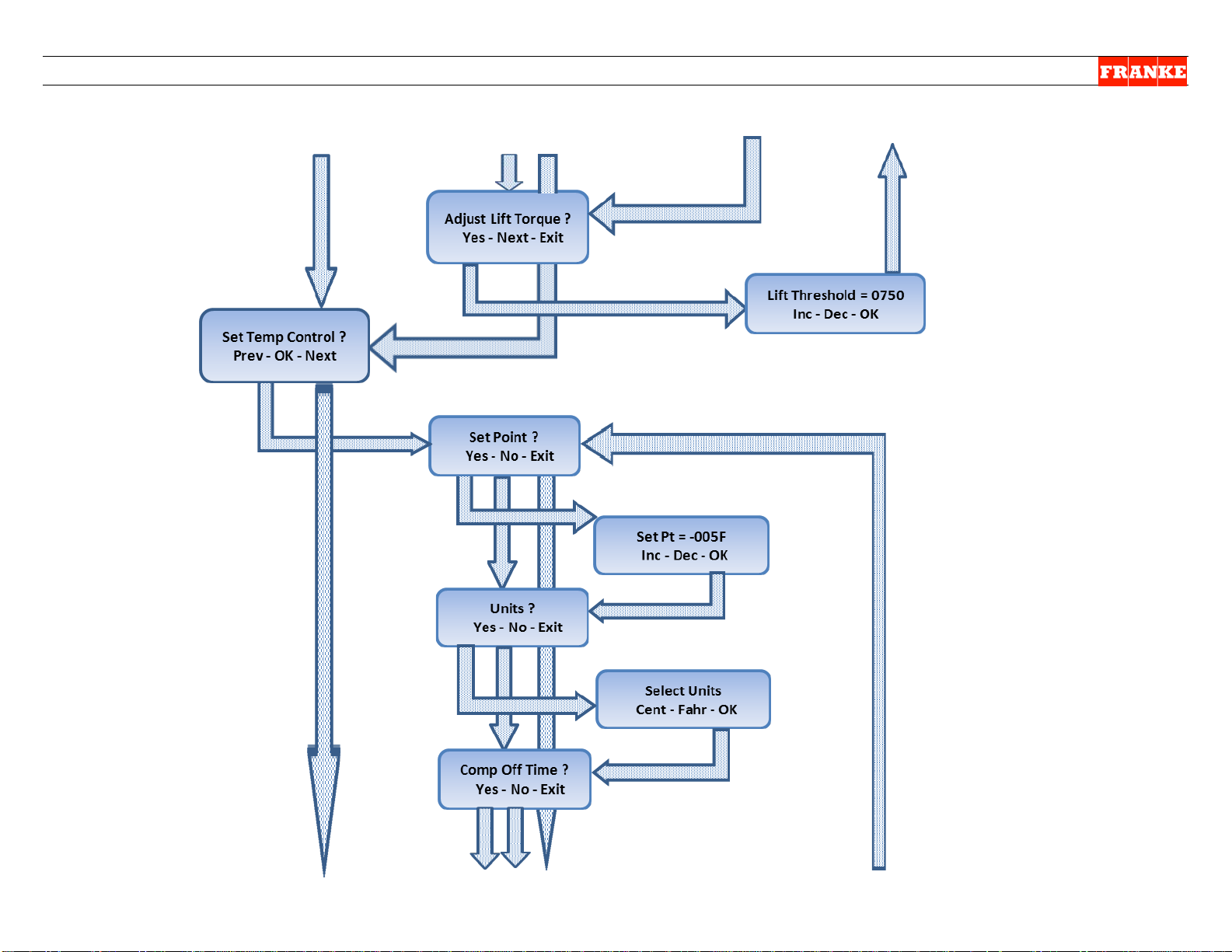
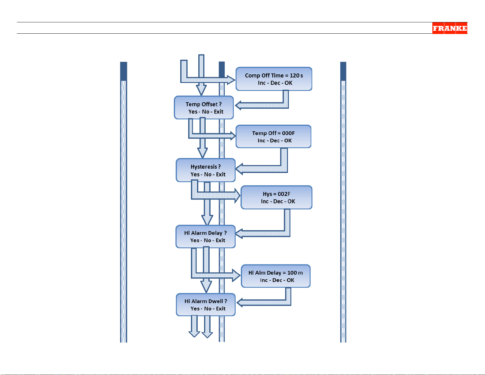
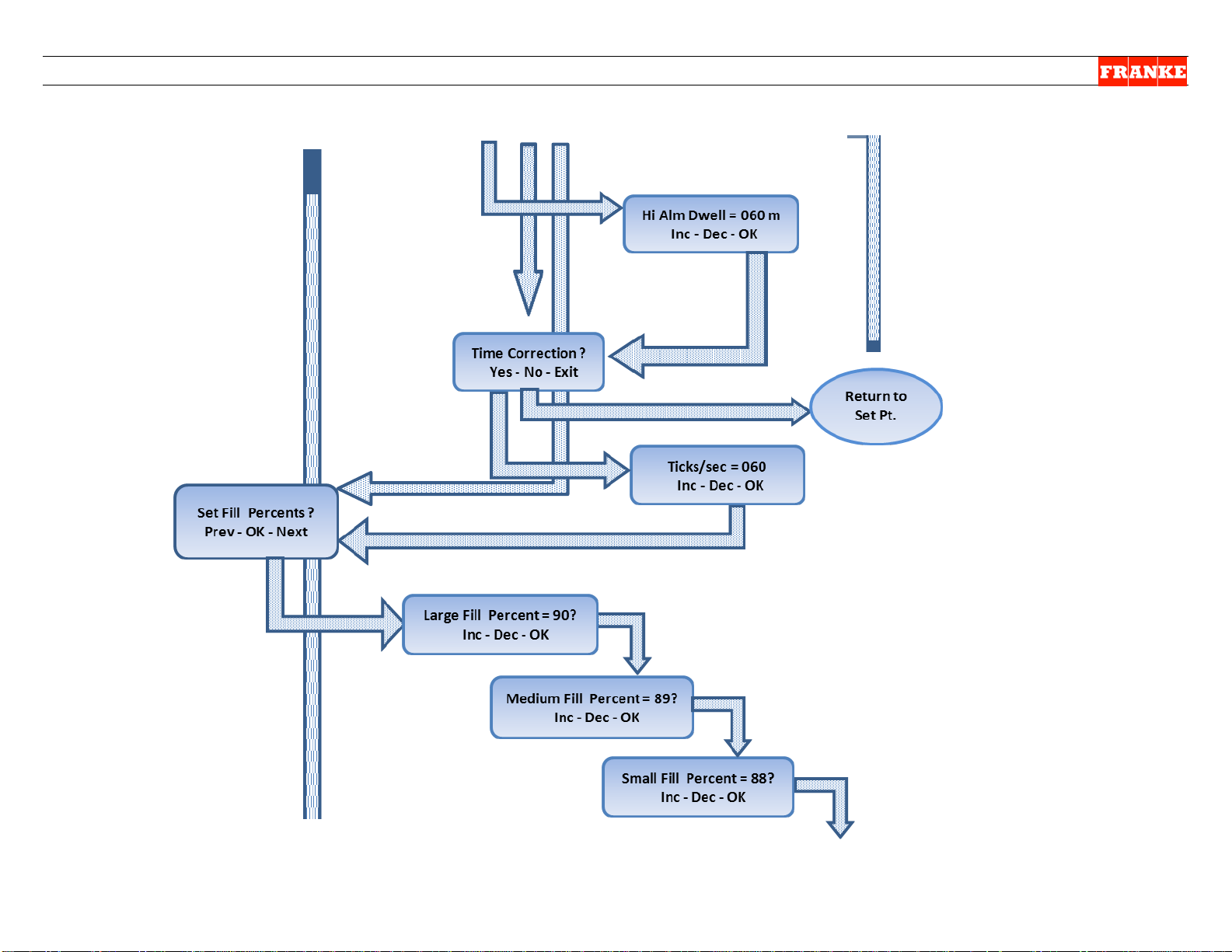
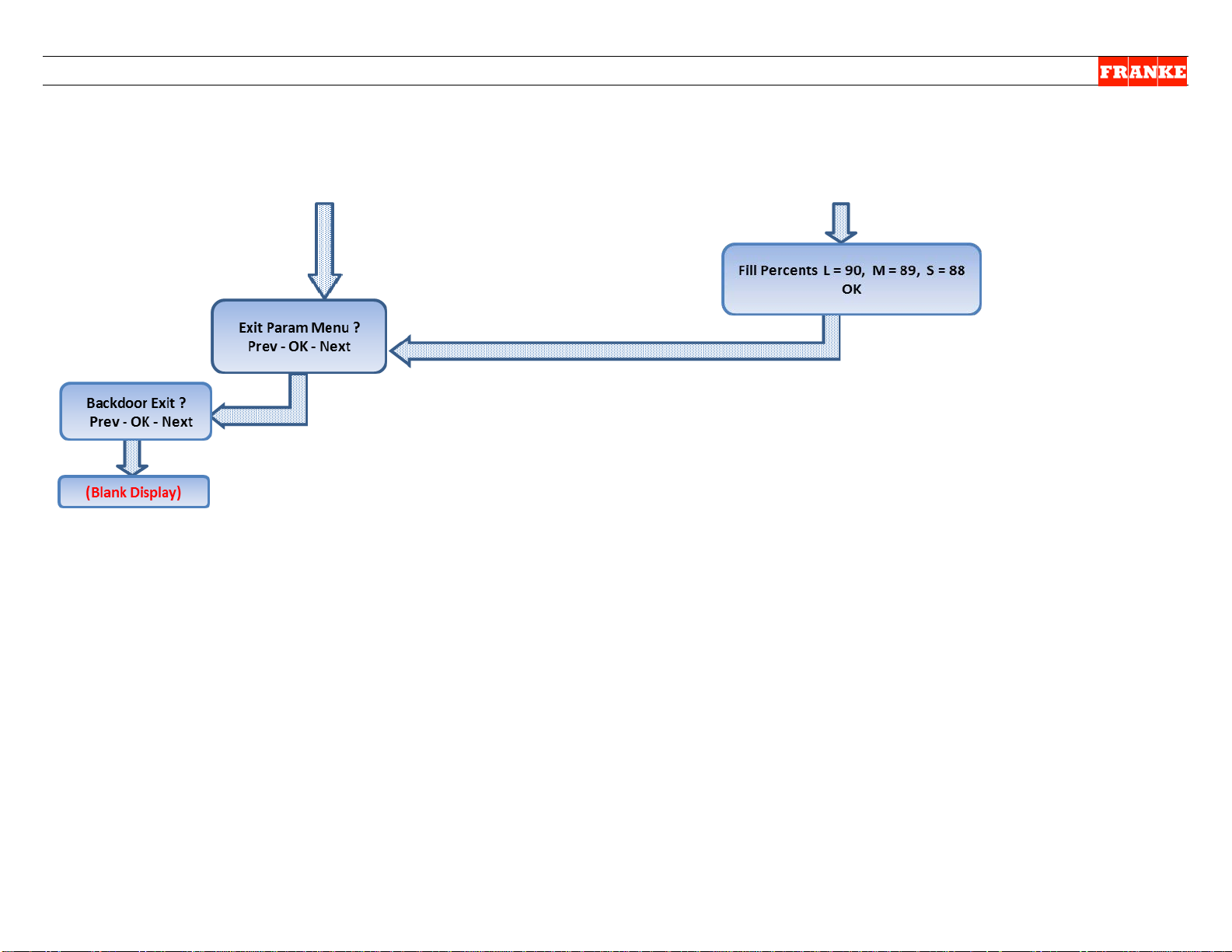
Parameter Access & Programming
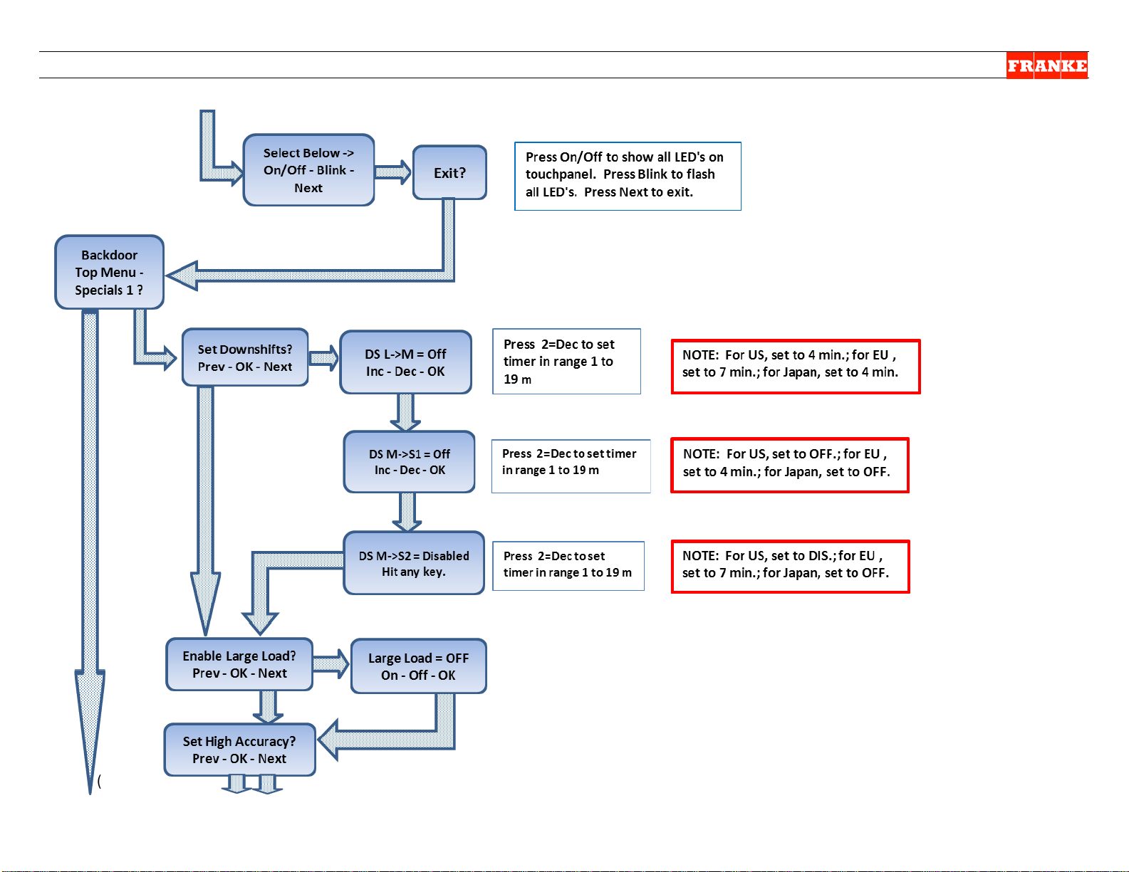
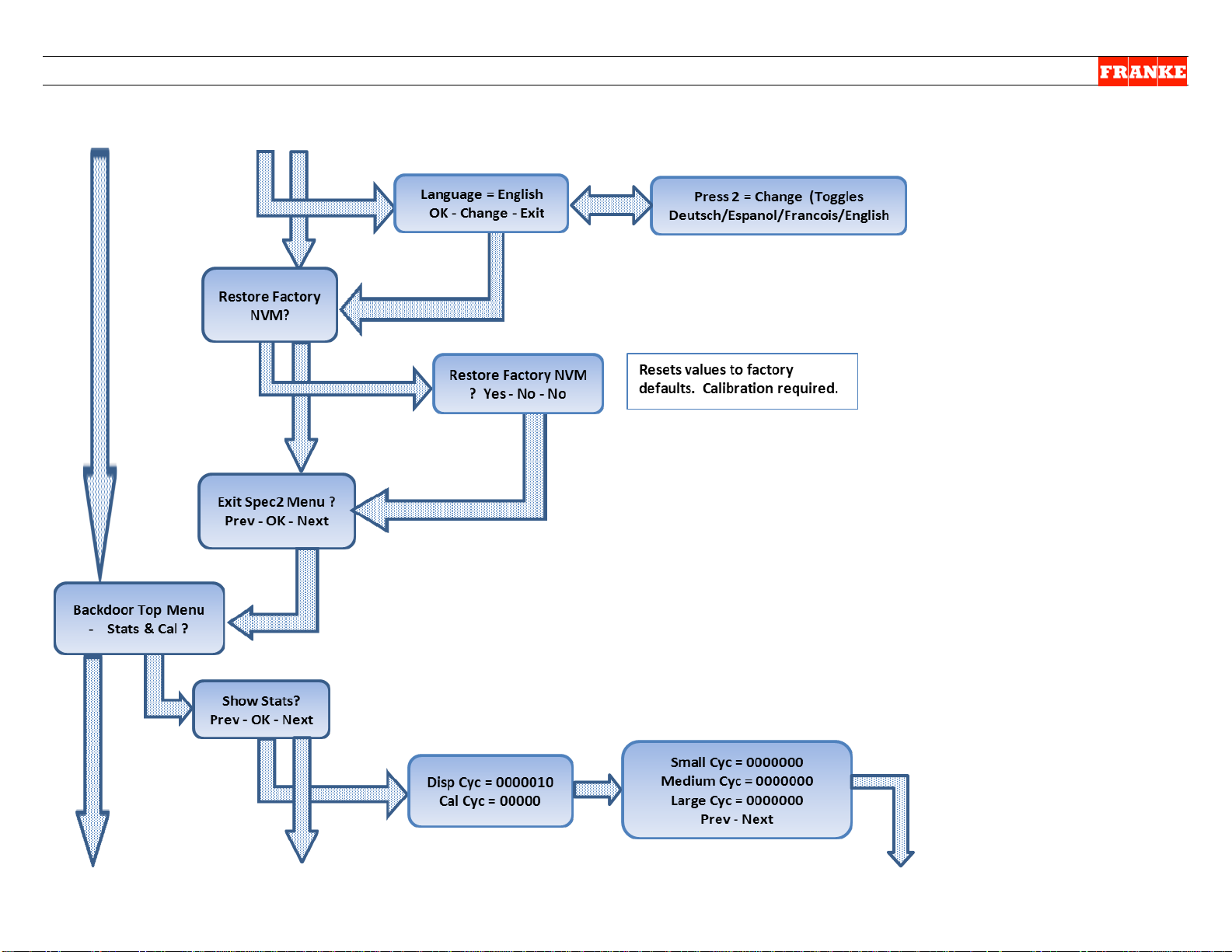
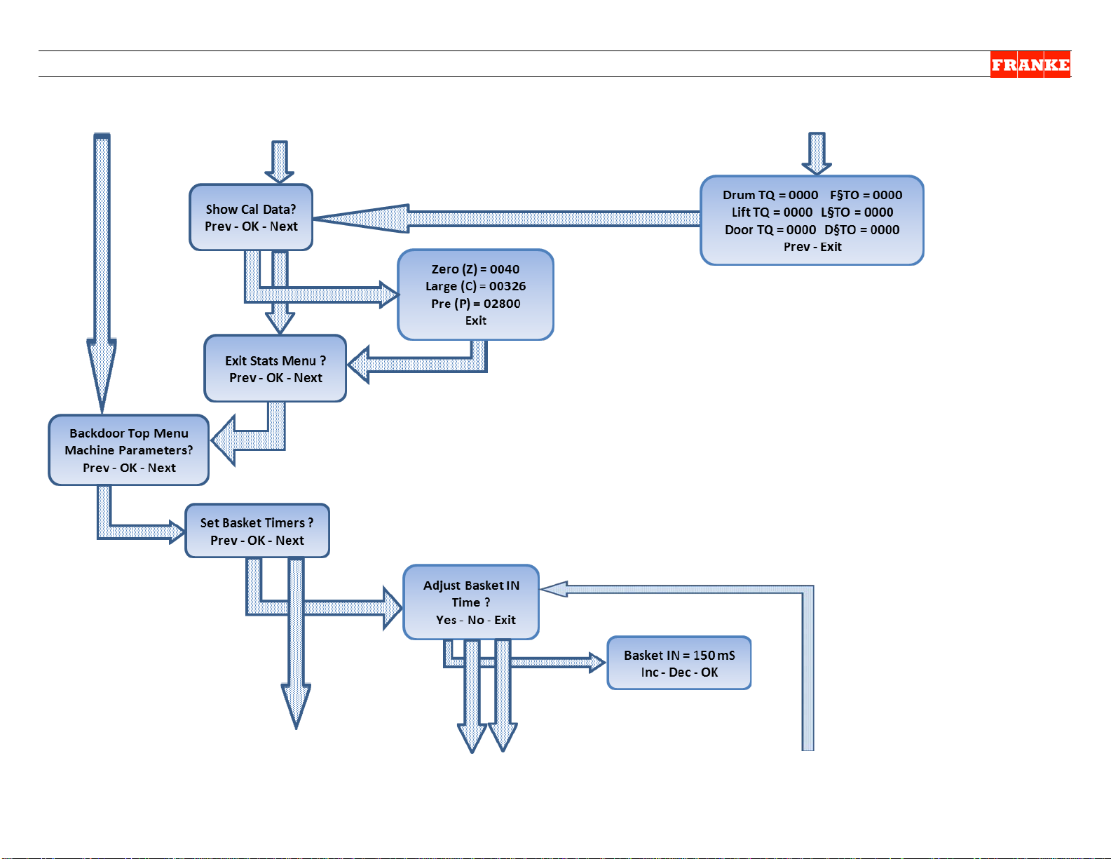
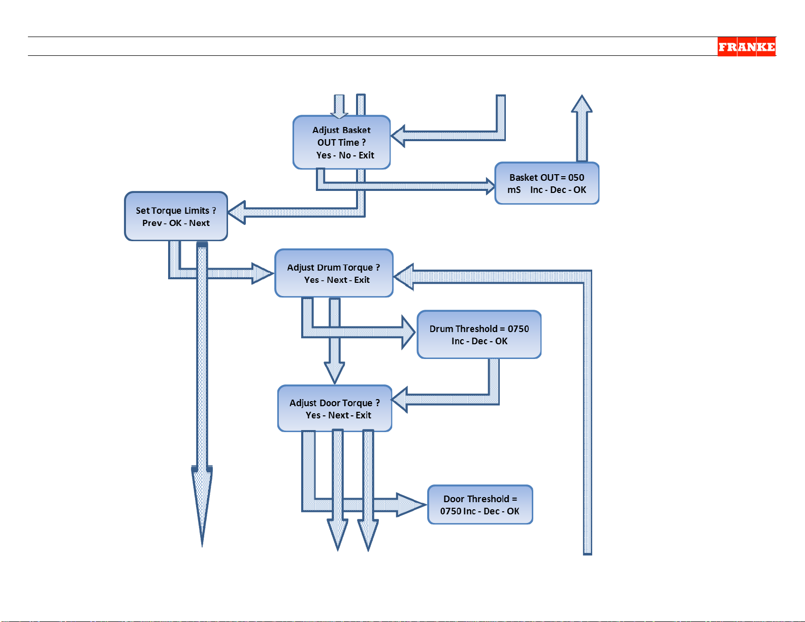
The original F3D3 Models (with H46N
Firmware) were programmed with Factory
Level operating and service diagnostic
parameters that required sequential boredown through multiple l evels, to check or
make any changes. Using the front
operator interface touch panel & display
to access:
1) Leave unit plugged in.
2) Turn Main Power Switch ON.
3) Lane power must be OFF. Display will
be blank or show current freezer
temperature, depending on the lane.
three choice buttons labeled: 1, 2 and 3 above.
3
4A
4B
4C
4D
next digit]
next digit]
last digit], then:
then:
Enter Password 0 _ _ _
Enter Password 0 0 _ _
Enter Password 0 0 0 _
Enter Password 0 0 0 0
Enter Password 0 0 0 1
Follow Flow Chart Diagr am on pa ges 2-12 to access Parameters.
Rev. 1 11/2012
Questions? Call Franke Technical Support Group For Your Area. Copyright 2012 Franke, Inc. All rights reserved.
Page 17
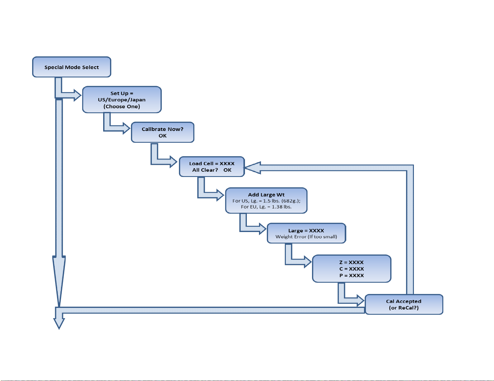
(Go to P age 3)
Page 2
For Models with Firmware F3D3 Main Version: H46N ONLY
Questions? Call Franke Technical Support Group For Your Area. Copyright 2012 Franke, Inc. All rights reserved.
Page 18
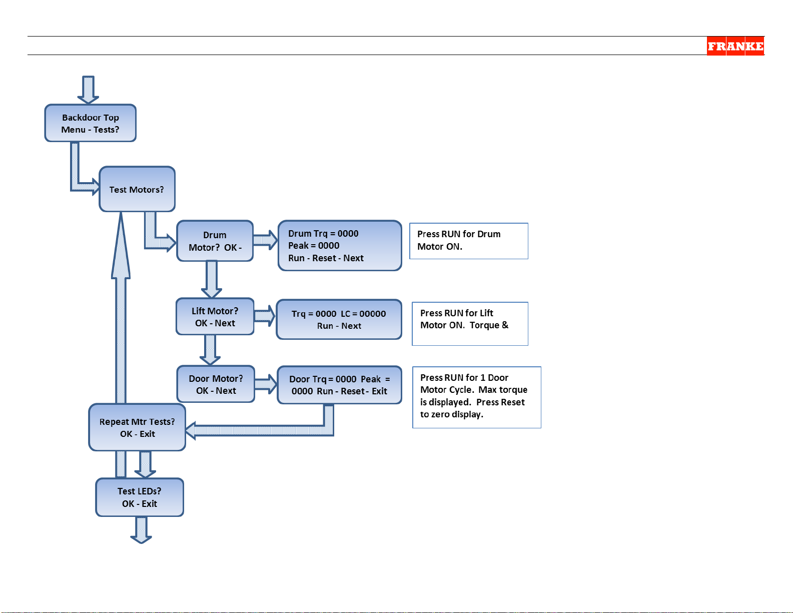
F3D3 Series Service Manual Display Menu for H46N Firmware/ 1.11.4
(From Page 2)
(Go to Pag e 4)
Page 3
For Models with Firmware F3D3 Main Version: H46N ONLY
Questions? Call Franke Technical Support Group For Your Area. Copyright 2012 Franke, Inc. All rights reserved.
Page 19
F3D3 Series Service Manual Display Menu for H46N Firmware/ 1.11.4
(From Page 3)
(Go to Page 5)
Page 4
For Models with Firmware F3D3 Main Version: H46N ONLY
Questions? Call Franke Technical Support Group For Your Area. Copyright 2012 Franke, Inc. All rights reserved.
Page 20

F3D3 Series Service Manual Display Menu for H46N Firmware/ 1.11.4
(From page 4)
(Go to P age 6)
Page 5
For Models with Firmware F3D3 Main Version: H46N ONLY
Questions? Call Franke Technical Support Group For Your Area. Copyright 2012 Franke, Inc. All rights reserved.
Page 21
F3D3 Series Service Manual Display Menu for H46N Firmware/ 1.11.4
(Go to P age 7)
Page 6
For Models with Firmware F3D3 Main Version: H46N ONLY
(From page 5)
Questions? Call Franke Technical Support Group For Your Area. Copyright 2012 Franke, Inc. All rights reserved.
Page 22
F3D3 Series Service Manual Display Menu for H46N Firmware/ 1.11.4
(From page 6)
(Go to P age 8)
Page 7
For Models with Firmware F3D3 Main Version: H46N ONLY
Questions? Call Franke Technical Support Group For Your Area. Copyright 2012 Franke, Inc. All rights reserved.
Page 23
F3D3 Series Service Manual Display Menu for H46N Firmware/ 1.11.4
(Go to P age 9)
Page 8
For Models with Firmware F3D3 Main Version: H46N ONLY
(From Page 7)
Questions? Call Franke Technical Support Group For Your Area. Copyright 2012 Franke, Inc. All rights reserved.
Page 24
F3D3 Series Service Manual Display Menu for H46N Firmware/ 1.11.4
(Go to p age 10)
Page 9
For Models with Firmware F3D3 Main Version: H46N ONLY
(From Page 8)
Questions? Call Franke Technical Support Group For Your Area. Copyright 2012 Franke, Inc. All rights reserved.
Page 25
F3D3 Series Service Manual Display Menu for H46N Firmware/ 1.11.4
(Go to P age 11)
Page 10
For Models with Firmware F3D3 Main Version: H46N ONLY
(From Page 9)
Questions? Call Franke Technical Support Group For Your Area. Copyright 2012 Franke, Inc. All rights reserved.
Page 26
F3D3 Series Service Manual Display Menu for H46N Firmware/ 1.11.4
Page 11
For Models with Firmware F3D3 Main Version: H46N ONLY
(From Page 10)
(Go to Page 12)
Questions? Call Franke Technical Support Group For Your Area. Copyright 2012 Franke, Inc. All rights reserved.
Page 27
F3D3 Series Service Manual Display Menu for H46N Firmware/ 1.11.4
Page 12
For Models with Firmware F3D3 Main Version: H46N ONLY
(From page 11)
Questions? Call Franke Technical Support Group For Your Area. Copyright 2012 Franke, Inc. All rights reserved.
Page 28
F3D3 Series Service Manual - Factory Lev3 Parameter Access / 1.11A
To Access Factory Level 3 Parameters:
Step
Action Required
Resulting Display
1
From Standby condition use 3rd touchpad to
enter: 3 3 3 3. [The Entry Code]
Special Mode Select
Cust Fact Exit
2
Press touchpad 2 = Fact(ory)
Factory Access Level
Lev1 Lev3 Exit
Press touchpad 2 = Lev3
Password ??
Inc OK Exit
Press touchpad 2 = OK [Icon will move right to
Password ??
Inc OK Exit
Press touchpad 2 = OK [Icon will move right to
Password ??
Inc OK Exit
Press touchpad 2 = OK [Icon will move right to
Password ??
Inc OK Exit
Press touchpad 1 = Inc once, to raise to 1,
Password ??
Inc OK Exit
Press touchpad 2 = OK
Language [first Parameter]
++ -- ->
See Parameter Spreadsheet for P-numbers, functions & default settings.
NOTE Software Codes and exceptions that apply.
Notes:
Command Key: ++ to scroll up; -- to scroll down; -> to move flashing
underscore __ under next value; == to accept or OK value or setting
P02
Example:
Press 1 = ++ to increase temp. value [-0004]
Press 3 = == to accept (new) setting
Set Point [Refrig er at or t em p.]
++ -- ==
NOTE: All programming is done using the
1
2
3
Parameter Access & Programming
F3D3 Series Fries Dispensers provide easy
access to Factory Level operating and
service diagnostic parameters using the
front operator interface touch panel &
display. To access:
1) Leave unit plugged in.
2) Turn Main Power Switch ON.
3) Lane power must be OFF. Display will
be blank or show current freezer
temperature, depending on the lane.
three choice buttons labeled: 1, 2 and 3 above.
3
4A
4B
4C
4D
5
next digit]
next digit]
last digit], then:
then:
Enter Password 0 _ _ _
Enter Password 0 0 _ _
Enter Password 0 0 0 _
Enter Password 0 0 0 0
Enter Password 0 0 0 1
P01 = English
Set Point
Questions? Call Franke Technical Support Group For Your Area. Copyright 2012 Franke, Inc. All rights reserved.
Press 2 = -- to decrease temp. value [- 0006 ]
P02 = -0005 F
Rev. 1 6/2012
Page 29

F3D3 Series Service Manual Factory Level 3 Parameter Access / 1.11A
Parameter
Range
Unit3)
Default
Notes
Country Exceptions
No.
Name
Low
High
US
EU
JP
LA
CN
AP
EU-B
US-
GM
CAN-
GM
Other
-GM
EU-Y
P01
Language
1 5
1
1=English, 2=Deutsch,
5=French/English (Canada)
1 1 1 1 5 1 1 1 5 1 1
P02
Set Point
-50
20
Deg F
-5
Temperature set point
P03
Offset
P04
Point
-100
50
Deg F
40
alarm (LON Models only)
P05
High Alarm (Start
Up) Delay
1
300
minutes
100
signal, until message appears
P06
High Alarm Dwell
1
300
minutes
60
Temperature must remain (dwell)
for this time
P07
Hysteresis
0.5 5 Deg F
1.0
Used in temperature control
P09
Time
1
200
seconds
120
must be off before restarting.
P10
Down Shift LM
1
20=off
minutes
4
large to medium. 20 = Off
4 7 4 4 4 4 Off
Off
Off
Off
10
P11
Down Shift M1S
1
(20= off)
minutes
20 (off)
from medium to small. 20 = Off
Off 3 Off
Off
Off
Off
Off
Off
Off
Off
5
Off 7 Off
Off
Off
Off
Off
Off
Off
Off
10
P13
Thres(hold)
10
1500 750
counts/amp of motor current.
P14
Thres(hold)
10
1500 750
counts/amp of motor current.
Lift (Motor)
P16
Basket In Time
10
1500
mS
150
to trigger a dispense cycle
150
350
150
150
150
150
150
150
150
150
150
Factory Level 3 - Parameter Guide – Page 1
[For Latest Models with BL 2.00; APP 2.12a Chip Software1)]
Factory
3=Espanola, 4=Francais,
-30 30 Deg F 8 Temperature offset from sensor
High Alarm Set
Temperature that triggers a high
GM Exceptions
P12
P15
Compressor Off
Down Shift M2S
Drum (Motor)
Torq(ue)
Door (Motor)
Torq(ue)
Torq(ue)
Thres(hold)
(M)
(M)
(S)
19
19
1
10 1500 750
19
(20= off)
(M)
(M )
(M)
minutes 20 (off)
Time to wait after high alarm
Minimum time the compressor
Time for a size downshift from
Time for an initial size downshift
Time for subsequent size
downshift from medium to small.
20 = Off
Motor stops if threshold
exceeded. Approx 250
Motor stops if threshold
exceeded. Approx 250
Motor stops if threshold
exceeded. Approx 250
counts/motor current.
Time the basket must remain in
NOTES: 1) No Main Board Chip Label. Software Vers(ion): BL 2.00; APP 2.12a appears on Lane Display.
Questions? Call Franke Technical Support Group For Your Area. Copyright 2012 Franke, Inc. All rights reserved.
Page 30
F3D3 Series Service Manual Factory Level 3 Parameter Access / 1.11A
Range
Unit3)
Default
Notes
Country Exceptions2)
No.
Name
Low
High
US
EU
JP
LA
CN
AP
EU-B
GM
GM
-GM
EU-Y
P17
Basket Out Time
10
1500
mS
50
out before enabling dispense
P18
Enable
Off
On On
being displayed.
P19
Enable
Off
On Off
slower) dispense for Japan.
Off
Off
On
Off
Off
Off
Off
Off
Off
Off
Off
P21
Large Fill Pct
P22
Medium Fill Pct
50
100
%
89
Reserved - Do not adjust.
P26
Toggle Rate
1 4
3
2 = Slow, 3 = Med, 4 = Fast)
P27
Display Units
C F
F
Temperature Display Units
Celsius or Fahrenheit
F C C C C C C F C
C
C
P28
Backdoor Type
English
Numeric
English
Displays numeric codes with
English or numeric codes only
Medium (Load)
75
P30
Factor
25
100 % 50
of large load
50
50
50
50
50
50
67
50
50
50
34
P31
Part Number
15 characters maximum. 1st must be 0-9 or F. 2nd must be 0-9, S, ‘.’ or ‘-‘. All others: 0-9, ‘-‘ or ‘.’
P32
Serial Number
P99
Factory Level 3 - Parameter Guide – Page 2
[For Latest Models with BL 2.00; APP 2.12a Chip Software1)]
Factory
Time the basket must remain
GM Exceptions
US-
CAN-
Other
P23
P29
Low Product
Hi Accuracy
Small Fill Pct
Dual Language
Factor
Small (Load)
Exit
50 100 % 90 Reserved - Do not adjust.
50 100 % 88 Reserved - Do not adjust.
25 100 % 67
15 characters maximum. All characters: 0-9 or ‘-‘
Prevents Low Product Warning
Enables high accuracy (but
If Dual Language is enabled,
this sets toggle rate: (1 = Off,
Weight of medium load as
percent of large load
Weight of small load as percent
Exits Level 3, if Entered
67 67 67 67 67 67 80 67 67 67
NOTES: 1) No Main Board Chip Label. Software Vers(ion): BL 2.00; APP 2.12a appears on Lane
Display. [How is this called up?]
2) Country Exceptions Abbreviations: US = North America; EU = Europe; JP = Japan; LA = Latin
America (South & Central); CN = Canada; AP = Asia, Pacific, Middle East & Australia
3) Unit Abbreviation: mS = Milliseconds
Questions? Call Franke Technical Support Group For Your Area. Copyright 2012 Franke, Inc. All rights reserved.
Page 31

F3D3 Series Service Manual Warranty/Section 1.2.1
Franke New Equipment Limited Warranty
Franke Foodservice Systems provides new equipment parts and labor warranties to the original
purchaser, which are equal to or exceed typical foodservice equipment m anufacturers. Special
(extended) warranty coverage may be negotiated with the customer. Extended compressor
warranties may also apply.
To determine if a Franke Frozen French Fry Dispenser is “in warranty”, contact: Franke Technical
Services at the numbers listed in Section 1.2.2 - Service Commitment & Contact Information. Be
prepared to provide the Model and Serial Number from the Manufacturers Data Plate located under
the louvered condenser filter access panel (F3D3 & F3D3S) or the upper right side of the freezer on
(F3D3P & F3D3PS) propane models.
On F3D3 & F3D3S Models On F3D3P & F3D3SP Models
Warranty Exclusions: Certain Franke parts that are expendable by nature and need to be replaced
frequently may not be cov er ed. In addition, Franke is not liable for repairs or damages due to
improper operation, attempted repairs or installation by unauthorized persons, alterations, poor water
quality, owner/operator abuse, fire, flood or acts of God. Fry basket storage racks and drip trays are
not covered by this warranty.
In Addition, this warranty may be voided in the case of:
• Failure to follow Franke instructions for use, care or maintenance
• Removal, alteration or defacing of the Franke-affixed serial number
• Service by a non-authorized service company
Warranty coverage is conditional upon Franke receiving notice of any defect subject to warranty
within thirty (30) days of its original discovery by the Buyer.
Rev. 1. 6/2012
Questions? Call Franke Technical Support Group For Your Area. Copyright 2012 Franke, Inc. All rights reserved.
Page 32

F3D3 Series Service Manual Service Commitment/Section 1.2.2
Contact Information - Americas:
Contact Information- Europe:
Contact Information- Asia, Pacific, Middle East & Africa:
The Franke Ser vice Commitment
Franke Foodservice Systems’ Technical Support Department and its third-party Service Network are
committed to meeting the unique service needs of restaurant operators worldwide. Accordingly, we strive to
provide the following response times to service requests for Franke-manufactured equipment:
1. Provide contact with the customer:
– Within 30 minutes of request for service during normal business hours
– Within 90 minutes after normal business hours (including weekends)
2. Perform service visit:
– The same day for emergency service*
– Within 24 hours for standard service
3. Target a 90% “first trip” fix rate
4. Provide 90-day warranty on the service performed
*An “emergency” is defined as an equipment operating condition that poses an immediate risk to the
safety of restaurant workers or customers.
This response time breakdown applies throughout the week and weekend. Due to varying customer locations,
and varying service agent locations and schedules, response rates may occasionally be extended. In these
situations, Franke Technical Support will work directly with the customer to find mutually acceptable options.
Franke reserves the right to use service agents outside of the Service Network, as needed.
Franke Technical Services
Franke Foodservice Systems
800 Aviation Parkway
Smyrna, TN 37167
United States of America
1-800-5FRANKE (1-800-537-2653); select 5
or
visit: FS-TS.US@Franke.com
Franke Technical Services
Franke Foodservice Systems China Co. Ltd.
318 Yinglang Industrial Zone
Shaping Town, Heshan City
Guangdong Provence, PRC – Postal Code: 5 297 00
Phone: +86 750 841 8476
Fax: +86 750 841 5845
Franke Technical Services
Franke Foodservice Systems GmbH
Jurastrasse 3
79713 Bad Saeckingen
Germany
Switchboard: +49 7761 52 400
Fax: +49 7761 52 408
Rev. 1. 6/2012
Questions? Call Franke Technical Support Group For Your Area. Page 1 Copyright 2012 Franke, Inc. All rights reserved.
Page 33

F3D3 Series Service Manual Troubleshooting Guide / Section 1.3
Use the following Sequence of Operation Questions to help diagnose common service problems.
The Question!
Answer!
What To Check or Do
1. Can the unit be
Check Breaker. OK? Yes = Continue No = Call electrician
Power Outlet OK? Yes = Continue No = Call electrician
Power Cord OK? Yes = Continue No = Replace Power Cord
per Section 2.23
Check power at Power Switch. OK? Yes = Continue to Question 2
No = Replace Power-ON Switch per Section 2.16
Yes!
Go to Question 2!
2. Do the Lane
No power to one lane only? “Push & Hold” touch pad for 4 seconds
Check 24-Volt AC Power Supply; OK? Yes = Continue No =
= Replace Operator Touchpad Panel per Section 2.15
PC Control Board OK? Yes = Continue No = Replace Control
Board per Section 2.20
Yes!
Go to Question 3!
3. Does the
Section 3.6
Section 2.17
Yes!
Go to Question 4!
4. Does the
Is Compressor plugged into terminal box? Yes = Continue No =
Plug it in! Verify Compressor starts.
Check Compressor Relay. OK? Yes = Continue No = Replace
Relay per Section 4.3
Check Compressor Capacitor. OK? Yes = Continue No =
Replace Capacitor per Section 4.3
Check refrigeration system for leak per Sections: 4.4, 4.4A &
4.4B. Yes = Repair leak per Section 4.5. No = Continue
Check Compressor. OK? Yes = Continue No = Replace
Yes!
Go to Question 5!
5. Does the
Check for French fries in hopper? Yes = Continue No = Add
fries to Hopper and attempt to dispense again.
Check for fries bridge inside Hopper? Yes = Clear/disrupt fries
bridge and attempt to dispense again. No = Continue
Is Drum Rotor binding inside Hopper? No = Continue Yes =
Alignment per Section 3.5
Check Drum Rotor Motor. Does it rotate freely? Yes = Continue
No = Replace Drum Rotor Motor per Section 2.5
turned ON?
controls light
up?
compartment
temperature appear
in left lane display?
NO!
NO!
NO!
(required) to turn on each lane. Is word Ready in displays? Yes =
Test & return unit to service; No = Continue
Replace Power Supply for that lane per Section 2.20
Ribbon Cable OK? Yes = Continue No = Replace Ribbon Cable
– Contact Franke Technical Support for P/N & Instructions
Operator’s Touchpad Panel OK? Yes = Return unit to service No
For two lane (F3D3 or F3D3P) Models, See
Temperature Display jumper re-cabling instructions
For single lane (F3D3S or F3D3SP) Models, Check Temperature
Controller Sensor Cable; OK? Yes = Continue No = Replace
Sensor Cable per
for Backup
Refrigeration
System start in two
minutes or less?
Warning: For F3D3P &
F3D3SP Propane
Models, attempt NO
Condenser System
Service! Call Franke.
Machine try to
dispense a load of
fries?
NO!
Condenser Unit per Section 4.7
Yes!
Adjust Drum Rotor Motor per Section 3.4 or Adjust Fry Hopper
Questions? Call Franke Technical Support Group For Your Area. Copyright 2012 Franke, Inc. All rights reserved.
Page 34

F3D3 Series Service Manual Troubleshooting Guide / Section 1.3
NO!
The Question!
Answer!
What To Check or Do
6. Can you simulate
the door?
Check Load Cell calibration per Section 1.9 instructions. OK? Yes
Yes!
Go to Question 7!
7. Can you
Does Control Panel indicate Load Ready? Yes = Continue No =
Yes = Continue No = reassemble Hopper, Drum & Baffle
Check wiring harness from Bump Switch to PC Control Board OK?
Franke Technical Support for P/N & Instructions
Check Bump Switch. OK? Yes = Continue No = Replace
Basket Fill Plunger Switch per Section 2.13
Yes!
The darn thing works. Don’t bother us!
Go to Question 6!
a load by pulling
down on the
product door frame
while it is running
dispense a load by
pushing the bump
switch?
NO!
NO!
= Continue No = Replace Load Cell per Section 2.10
Press and hold LANE OFF/ON button for four seconds. Did Ready
appear in display and basket lights come on within 20 seconds?
Yes =Continue No = connect or replace harness. Contact
Rev. 1 6/2012
Questions? Call Franke Technical Support Group For Your Area. Copyright 2012 Franke, Inc. All rights reserved.
Page 35

F3D3 Series Service Manual Error Message Guide / Section 1.4
Error
Code
Display Window Message
Error Description
Action Required
Ready
Small
Low Product Warning
Add fries to hopper.
01
Err01
Reset
Tare Time Out
See Advanced Troubleshooting
02
Err02
Reset
No Bucket
Check rubber dispense bucket
03
Err03
Reset
Drum Torque Error in Pre-
Empty fries from Hopper and refill.
04A
Err04
Reset
Fill Time Out (with Low
Add fries to hopper.
04B
Err04
Reset
05
Err05
Reset
Drum Torque Error in
Empty fries from Hopper. Test
06
Err06
Reset
Lift Torque Error
All F3D3 Series Frozen French Fries Dispensers have
lane control panels that display unit status and
common Error Messages. The following table lists all
Error Messages and the lane condition or action
required to correct the problem.
---
Low Fry Level
Load Cell Error
Call for Service
No Bucket
Recheck Assembly
Drum Stuck
Empty Hopper & Refill
Hopper Empty
Add Fries
Fry Bridge
Clear Fry Bridge
Pulse Mode
Product Warning ON*)
Fill Time Out (with Low
Product Warning OFF*)
Continue dispensing until Err04A
Message appears.
Section 1.3.
See Load Cell Calibration Section
LCC.
and loading doors.
Press Reset (bottom-right)
touchpad to reset.
Press Reset (bottom-right)
touchpad to reset.
Press Reset (bottom-right)
touchpad to reset.
Clear any fry bridge in hopper.
Press Reset (bottom-right)
touchpad to reset.
Drum Stuck
Empty Hopper
Bucket Lift Error
Call for Service
* When Hopper Level is below Low Product Sensor, display flashes “Low Fry Level” and three LEDs around ‘!’ warning triangle illuminate.
Questions? Call Franke Technical Support Group For Your Area. Page 1 Copyright 2012 Franke, Inc. All rights reserved.
Pulse Mode
rotation of drum.
Press Reset (bottom-right)
touchpad to reset.
Page 36

F3D3 Series Service Manual Error Message Guide / Section 1.4
Continued…
Error
Code
Display Window Message
Error Description
Action Required
07-1
Err07-1
Reset
Sensor Unplugged
Check door-open sensor. If
07-2
Err07-2
Reset
Door Torque Error in
Clear dispense area.
07-3
Err07-3
Door Motor Unplugged
Check 24-volt power to door motor
replace motor.
08
Err08
Reset
Door Torque Error in
Call for Service.
09
Err09
Reset
Complete PN/SN
Enter PN/SN (part number/serial
Doors Stuck
Clear Dispense Area
Doors Stuck
Clear Dispense Area
Doors Stuck
Clear Dispense Area
Reset
Doors Stuck
Call for Service
Forward (Open) Direction
Reverse (Close) Direction
unplugged, plug it in. If faulty,
replace sensor.
Press Reset (bottom-right)
touchpad to reset.
or run Motor Test. (See SM
Section CLPA – Customer Level
Programming Access) If faulty,
Check door open motor for
obstruction.
For Special Models with LON Works Smart Kitchen Package ONLY!
Missing PN/SN
Enter PN/SN
information not available
for LON communications.
number) information, per LON
Installation Instructions
Questions? Call Franke Technical Support Group For Your Area. Page 2 Copyright 2012 Franke, Inc. All rights reserved.
Page 37

F3D3 Series Service Manual Error Message Guide / Section 1.4
Issued 4/2011
Questions? Call Franke Technical Support Group For Your Area. Page 3 Copyright 2012 Franke, Inc. All rights reserved.
Page 38

F3D3 Series Service Manual Parts List & Component Diagrams / Section 1.5
Part Numbers
Key No.
Quantity
Description
120-Volt/60 Hz
230-Volt/50 Hz
1
1 ea.
Back Panel (Service Access)
18005391
18005391
2
1 ea.
Side Access Panel
19003067
19003067
3
1 ea.
Removable Air Inlet (Filter Access Panel)
19003751
19003751
4
1 ea.
Condenser Filter
19003756
19003756
5
2 ea.
Swivel Caster (front) with Brake
562501
562501
6
2 ea.
Swivel Caster (rear)
19000746
19000746
7
1 ea.
Cord Set
19000801
19000826
Access Panels, Filter & Casters (Single Lane Only)
Questions? Call Franke Technical Support Group For Your Area. Page 1 Copyright 2011 Franke, Inc. All rights reserved.
Page 39

F3D3 Series Service Manual Parts List & Component Diagrams / Section 1.5
8
1 ea.
Condensing Unit w/cordset
19003221
19003222
Part Numbers
Key No.
Quantity
Description
120-Volt/60 Hz
230-Volt/50 Hz
9
2 ea.
End Rail (Hopper side support)
18003324
18003324
10
1 ea.
Bucket, Silicone (fries)
19002725
19002725
11
1 ea.
Hopper & Rotor Assembly
12
1 ea.
Baffle, Rubber (for Hopper)
19000247
19000247
13
1 ea.
Removable Bottom (red silicone rubber)
19003754
19003754
14
1 ea.
Wire-form Drip Tray (dispense lane guide)
19004013
19004013
15
1 ea.
Wire Rack, Bottom Fry Basket Support
19003757
19003757
Freezer & Dispensing Loose Component Parts (Single Lane Only)
Questions? Call Franke Technical Support Group For Your Area. Page 2 Copyright 2011 Franke, Inc. All rights reserved.
18004870 18004870
Page 40

F3D3 Series Service Manual Parts List & Component Diagrams / Section 1.5
16
1 ea.
Bottom Drip Tray
19003753
19003753
Part Numbers
Key No.
Quantity
Description
120-Volt/60 Hz
230-Volt/50 Hz
17
1 ea.
Freezer Door Assembly
18004866
18004866
18
1 ea.
Gasket, Freezer Door Case
19003748
19003748
19
1 ea.
Door Hinge, Top (RH)/Bottom (LH)
18002224
18002224
20
2 ea.
Door Bushing, Bronze
3700894
3700894
21
4 ea.
Screw, Flanged
19003057
19003057
Freezer Door Parts (Single Lane Only)
Questions? Call Franke Technical Support Group For Your Area. Page 3 Copyright 2011 Franke, Inc. All rights reserved.
Page 41

F3D3 Series Service Manual Parts List & Component Diagrams / Section 1.5
22
1 ea.
Door Hinge, Bottom (RH)/Top ( LH)
18002225
18002225
Part Numbers
Key No.
Quantity
Description
120-Volt/60 Hz
230-Volt/50 Hz
23
1 ea.
Rotor Drive Sub-Assembly
18003285
18003285
24
1 ea.
Rotor Motor, Gear Reduction
19002708
19002708
25
1 ea.
Retaining Ring, External
19000238
19000238
26
1 ea.
Washer, Sensor Retaining
17002997
17002997
27
1 ea.
Product (present) Sensor
19000384
19000384
Hopper Rotor Drive & Product Sensor (All F3D3 Versions)
Questions? Call Franke Technical Support Group For Your Area. Page 4 Copyright 2011 Franke, Inc. All rights reserved.
Page 42

F3D3 Series Service Manual Parts List & Component Diagrams / Section 1.5
28
1 ea.
Sleeve, Product Sensor
19000383
19000383
29
1 ea.
Heat Wire, 1760 mm, 3 watts/ft.
19003973
19003975
Part Numbers
Key No.
Quantity
Description
120-Volt/60 Hz
230-Volt/50 Hz
30
1 ea.
Touch Pad Overlay
31
1 ea.
Backing Plate, Touch Pad Overlay
19003901
19003901
32
1 ea.
PCB Controller (Master Control Board)
19003899
19003899
33
6 ea.
Standoff, Overlay Mounting (M4 x 18)
19002776
19002776
34
4 ea.
Screw, Overlay Mounting (M4 x 8)
19002745
19002745
35
1 ea.
Rocker Switch, Main Power-ON/OFF
385.151
385.151
36
1 ea.
Front Bezel, Control Panel, w/studs
19004012
19004012
Control Panel & Master Board (All F3D3 Versions)
Questions? Call Franke Technical Support Group For Your Area. Page 5 Copyright 2011 Franke, Inc. All rights reserved.
19003900 19003900
Page 43

F3D3 Series Service Manual Parts List & Component Diagrams / Section 1.5
37
4 ea.
Screws, Front Bezel Mounting
19003058
19003058
38
1 ea.
Heat Wire, 2860 mm, 3 watts/ft.
19003972
19003974
Part Numbers
Key No.
Quantity
Description
120-Volt/60 Hz
230-Volt/50 Hz
39
1 ea.
DIN Rail Mounting Bracket
17017004
17017004
40
4 ea.
Screw, DIN Rail Mounting Bracket
3118101
3118101
41
1 ea.
DIN Rail (35 x 230 mm)
19000366
19000366
42
2 ea.
Screw, DIN Rain Mounting (to Bracket)
19002869
19002869
43
1 ea.
Power Supply, 24V DC SIEMENS
44
1 ea.
Relay, 30A/24V DC DPST - Schneider
19003558
19003558
45
2 ea.
Terminal Block Module
3588201
3588201
46
3 ea.
Terminal Block Module
3588202
3588202
DIN Rail & Mounted Electric Components (Electrical Components All F3D3 Versions)
Questions? Call Franke Technical Support Group For Your Area. Page 6 Copyright 2011 Franke, Inc. All rights reserved.
19003762 19003762
Page 44

F3D3 Series Service Manual Parts List & Component Diagrams / Section 1.5
47
1 ea.
Terminal Block Module
3588203
3588203
48
2 ea.
End Stop Terminal Blocks
3588206
3588206
Part Numbers
Key No.
Quantity
Description
120-Volt/60 Hz
230-Volt/50 Hz
49
1 ea.
Door Lift Assembly
18003834
18003834
50
4 ea.
Flat Washer, Stainless Steel (M6)
19001569
19001569
51
4 ea.
Lock Washer , Stainless Steel (M6)
19001570
19001570
52
4 ea.
Nut , Stainless Steel (M6)
19000492
19000492
60*
1 ea.
Spring, Extension
19000213
19000213
61
1 ea.
Bushing, Bronze (9.4 mm long)
62
1 ea.
Bushing, Bronze (6.3 mm long)
19003680
19003680
63
1 ea.
Bushing, Plastic (5.6 mm)
19003682
19003682
64
1 ea.
Cotter Pin, Brass
19002985
19002985
Automation Assembly & Door Spring Sub-Assembly (All F3D3 Versions)
Questions? Call Franke Technical Support Group For Your Area. Page 7 Copyright 2011 Franke, Inc. All rights reserved.
19003681 19003681
Page 45

F3D3 Series Service Manual Parts List & Component Diagrams / Section 1.5
65
1 ea.
Screw, Stainless Steel (M5x8)
19001582
19001582
Part Numbers
Key No.
Quantity
Description
120-Volt/60 Hz
230-Volt/50 Hz
53
1 ea.
Load Cell
54
1 ea.
Load Cell Base
19000187
19000187
55
1 ea.
Stop Bolt, Load Cell
19002767
19002767
56
1 ea.
Nut, Stop Bolt, Stainless Steel (M6)
19001576
19001576
57
2 ea.
Screw, Cell-to-Base (M6x50)
19001564
19001564
58
4 ea.
Lock Washers (M6)
19001570
19001570
* Break in Key No. sequence is intentional. See Page 8 for Key Nos. 53-59.
Load Cell Assembly (All F3D3 Versions)
Questions? Call Franke Technical Support Group For Your Area. Page 8 Copyright 2011 Franke, Inc. All rights reserved.
19002732 19002732
Page 46

F3D3 Series Service Manual Parts List & Component Diagrams / Section 1.5
59
2 ea.
Screw, Load Cell Mounting (M6x40)
19001580
19001580
Part Numbers
Key No.
Quantity
Description
120-Volt/60 Hz
230-Volt/50 Hz
66
1 ea.
Arm Cam with Internal Flag
18001855
18001855
67
2 ea.
Motor (for Door Open & Lift Motor)
19002708
19002708
68
1 ea.
Optical Sensor with Mounting Bracket
18002665
18002665
69
8 ea.
Lock Washer #10
5046
5046
70
6 ea.
Screw, Motor Mounting - M5 40 mm long
19002765
19002765
Door Open & Lift Motors (All F3D3 Versions)
Questions? Call Franke Technical Support Group For Your Area. Page 9 Copyright 2011 Franke, Inc. All rights reserved.
Page 47

F3D3 Series Service Manual Parts List & Component Diagrams / Section 1.5
71
2 ea.
Screw, Motor Mounting – M5 35 mm long
19002766
19002766
72
1 ea.
Door Lift Shaft
19000198
19000198
Part Numbers
Key No.
Quantity
Description
120-Volt/60 Hz
230-Volt/50 Hz
10
1 ea.
Bucket, Silicone (fries)
19002725
19002725
73
2 ea.
Doors, Product Dispensing w/screws
19003534
19003534
Dispense Doors & Bucket (All F3D3 Versions)
Questions? Call Franke Technical Support Group For Your Area. Page 10 Copyright 2011 Franke, Inc. All rights reserved.
Page 48

F3D3 Series Service Manual Parts List & Component Diagrams / Section 1.5
Part Numbers
Key No.
Quantity
Description
120-Volt/60 Hz
230-Volt/50 Hz
74
1 ea.
Right Dispense Door Shaft
19002738
19002738
75
1 ea.
Left Dispense Door Shaft
19002737
19002737
76
6 ea.
Retaining Ring, external ½”
19000215
19000215
77
2 ea.
Seal, Door Shaft
19000891
19000891
78
2 ea.
Block , Door Rotation
19000193
19000193
79
1 ea.
Link, Door Actuator
19000194
19000194
80
2 ea.
Clevis Pin (4.55 x 38.1)
19000210
19000210
81
1 ea.
Clevis Pin (6.35 x 50.8)
19000211
19000211
82
1 ea.
Clevis Pin (6.35 x 38.1)
19000212
19000212
Door Shafts & Shaft Linkage (All F3D3 Versions)
Questions? Call Franke Technical Support Group For Your Area. Page 11 Copyright 2011 Franke, Inc. All rights reserved.
Page 49

F3D3 Series Service Manual Parts List & Component Diagrams / Section 1.5
83
2 ea.
Spacer
19000214
19000214
84
1 ea.
Cotter Pin, Ring Locking
19000170
19000170
Rev. 1 6/2011
Questions? Call Franke Technical Support Group For Your Area. Page 12 Copyright 2011 Franke, Inc. All rights reserved.
Page 50

F3D3 Series Service Manual El ec tric Sche m atics / Section 1.6
120-Volt Wiring Diagram
Questions? Call Franke Technical Support Group For Your Area. Page 1 Copyright 2012 Franke, Inc. All rights reserved.
Page 51

F3D3 Series Service Manual El ec tric Sche m atics / Section 1.6
230-Volt Wiring Diagram
Questions? Call Franke Technical Support Group For Your Area. Page 2 Copyright 2012 Franke, Inc. All rights reserved.
Page 52

F3D3 Series Service Manual El ec tric Sche m atics / Section 1.6
24-Volt Wiring Diagram (All F3D3S Models)
(Also Covers Dual Lane F3D3 Models)
Questions? Call Franke Technical Support Group For Your Area. Page 3 Copyright 2012 Franke, Inc. All rights reserved.
Page 53

F3D3 Series Service Manual El ec tric Sche m atics / Section 1.6
Danfoss Condensing Unit
Model LCHC0065RC____B Electric Schematic
Rev.1 7/2011
Questions? Call Franke Technical Support Group For Your Area. Page 4 Copyright 2012 Franke, Inc. All rights reserved.
Page 54

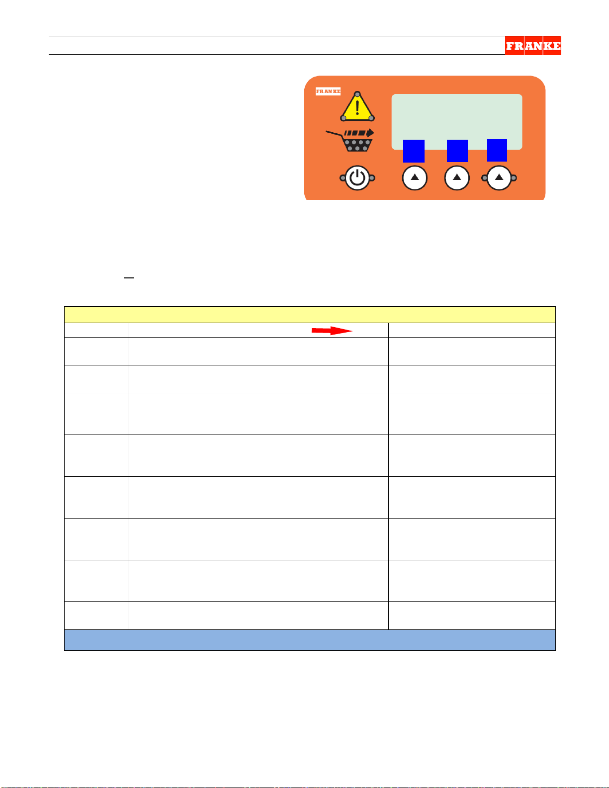
F3D3 Series Service Manual Control Panel Guide / Section 1.7
3 2 1
5 6 7
4
Control Panel Function QUICK-Guide:
Note: Newer lane
control overlays are
black.
F3D3 Series lane control panel overlays have the following touch pads, indicator lights and display:
1 . Lane POWER Touch Pad (With green right & lef t LED Lights)
Press to turn individual lane ON or OFF:
Press and Hold touch pad for 4 seconds to turn on. Lights will stay on.
Press and Hold touch pad for 4 seconds to turn off. Lights will turn off.
NOTE: Do not turn ON until hopper is filled with fries.
2 . Load READY Graphic (With 7 Green LED lights inside basket icon):
When lights are on, the lane is ready to dispense into a fry basket.
3 . Attention/Warning Graphic (With 3 LED Lights at corners):
This symbol communicates lane status:
No lights on – Unit status OK
Lights ON – Getting low on frozen fries in hopper, but unit will continue to dispense.
Lights Flashing – Error conditi on. See display (4) for error message & SM Section 1.4.
4 . Message Display Window
Displays current freezer operating temperature (in upper-right corner of left display)
Displays Error Messages (Err04, etc.)and possible causes and remedies
Displays unit Setup & Diagnostic Programs with possible actions or decision options.
5-7 Program Decision or Action Touch Pads
Three touch pads are evenly spaced under the Display Screen, which displays options: Inc
(increase) Dec (decrease) OK etc. Use the Action touch pad under the option (Inc/Dec/OK)
to initiate that action.
Rev.1 6/2012
Questions? Call Franke Technical Support Group For Your Area. Copyright 2012 Franke, Inc. All rights reserved.
Page 55

F3D3 Series Service Manual Customer Level Programming / 1.8
To Access Customer Leve l Program ming Functions:
Step
Action Required
Resulting Display
1
From Standby condition use 3rd touchpad and
enter: 3-3-3-3. [Entry code]
Special Mode Select
Cust Fact Exit
Press touchpad 1 = Cust[omer]
See Page 2 Table for language options.
Customer Access
Prev OK Next
Press touchpad 2 = OK [To change language]
Customer Access
Prev OK Next
Press touchpad 2 = OK [To change set temp]
Customer Access
Prev OK Next
Press touchpad 2 = OK [To calibrate load cell]
Customer Access
Prev OK Next
Press touchpad 2 = OK [To test motors]
Customer Access
Prev OK Next
Press touchpad 2 = OK [To view statistics]
Customer Access
Prev OK Next
3F
Press touchpad 2 = OK [To exit]
or Press touchpad 3 = Next [Goes back to Set Language]
See Page 2 Customer Function Guide for Sub-Menus & Options
NOTE: All programming is done using the
1
2
3
Customer Level Access
All F3D3 Series Fries Dispensers provide
easy access to Customer-Level operating
and diagnostic parameters, using the lane
operator-interface touch panels & displays.
For customer-level programming access:
1) Leave unit plugged in.
2) Turn Main Power Switch ON.
3) Lane power must be OFF. Display will
show current freezer temperature.
three choice buttons labeled: 1, 2 and 3 above.
2
3A
3B
3C
3D
3E
or Press touchpad 3 = Next [See next function]
or Press touchpad 3 = Next [See next function]
or Press touchpad 3 = Next [See next function]
or Press touchpad 3 = Next [See next function]
or Press touchpad 3 = Next [See next function]
Set Language ?
Set Temp Cntrl ? [Control]
Calibrate ?
Test Motors ?
View Statistics ?
Exit ?
Rev. 1 6/2012
Questions? Call Franke Technical Support Group For Your Area. Page 1 Copyright 2012 Franke, Inc. All rights reserved.
Page 56

F3D3 Series Service Manual Customer Level Programming / 1.8
Customer Level Functions
Sub-Menu Functions
Display Values
Notes
Customer Access
Lang = English
Press: OK Change or Exit
Lang = Deutsch
Press: OK Change or Exit
Lang = Espanol
Press: OK Change or Exit
Lang = Francais
Press: OK Change or Exit
Lang = Fr-Eng
Toggles between English-French-English, etc.
Customer Access
Set Point ?
Yes Exit
SetPt = -05F
Inc Dec OK
-05 F is the default temperature
Press 1 = Inc – To increase one degree, etc
Units ?
Yes Exit
Select Units
Cent Fahr
US default is Fahr [Fahrenheit]
All others default is Cent [Centigrade]
Customer Access
Calibrate Menu
Calibrate Menu
OK Exit
* Two-digit Load Cell TAR (no-load) value. Will
Customer Access
Drum Motor ?
Drum Motor
Run Reset Next
T = Motor Torque; P = Peak Torque
Press 3 = Next - to go to Lift Motor Test
Lift Motor ?
Lift Motor
Run Reset Next
L = Live Load Cell value; T = Motor Torque
Press 3 = Next - to go to Door Motor Tests
Door Motor ?
Door Motor
Run Reset Exit
T = Motor Torque; P = Peak Torque
Press 3 = Exit - to repeat Motor Tests
Customer Access
Disp Cyc = 0000000
Next
Reports the number of dispense cycles and
Small Cyc = 0000000
Prev Next
Reports the number of Small, Medium and Large
Drum TQ = 0000 F. TO=0000
Prev Next
Reports Drum, Lift and Door Motor over-torque
Zero (Z) = 00000
Prev Exit
Reports Load Cell Calibration values:
P (Pre-Load) Default is 2900
Set Language ?
Prev OK Next
Set Temp Cntrl (Control) ?
Prev OK Next
Calibrate ?
Prev OK Next
Test Motors ?
Prev OK Next
View Statistics ?
Prev OK Next
Begin ?
OK Exit
OK Next
OK Next
OK Next
Cal Cyc = 00000
Medium Cyc = 0000000
Large Cyc = 0000000
Lft TQ = 0000 L. TO=0000
Dor TQ = 0000 D. TO 0000
Load Cell = 0000*
All Clear?
T = 0000
P = 0000
L = 0000
T = 0000
T = 0000
P = 0000
cycle within a narrow range.
Press 1 = Run - To run Drum Motor
Press 2 = Reset - T o zero P value
Press 1 = Run - To run the Lift Motor
Press 2 = Reset - T o zero T value
Press 1 = Run - To run Lift Motor
Press 2 = Reset - T o zero P value
calibration cycles
loads dispensed
events; plus fill time-outs (F. TO), lift time-outs (L.
TO) and door time-outs (D. TO)
Large (C) = 00000
Pre (P) = 00000
Questions? Call Franke Technical Support Group For Your Area. Page 2 Copyright 2012 Franke, Inc. All rights reserved.
Z Default is 40
C Default is 326
Page 57

F3D3 Series Service Manual Load Cell Calibration / Section 1.9
Step
Action Required
Resulting Display
5
From Standby condition press touchpads:
3-3-3-3. [Entry code]
Special Mode Select
Cust Fact Exit
6
Press touchpad 1 = Cust
Lev2 – Customer Access
Prev OK Next
7 Press touchpad 3 = Next
Lev2 – Customer Access
Prev OK Next
8
Press touchpad 3 = Next
Lev2 – Customer Access
Prev OK Next
9
Press touchpad 2 = OK
Lev2 – Customer Access
OK Exit
Press touchpad 1 = OK
Lev2 – Customer Access
OK Exit
Press touchpad 1 = OK
Lev2 – Customer Access
Zero = XXXX
Lev2 – Customer Access
Preload = XXXX
Lev2 – Customer Access
OK
Add Large Weight = 1.5 lb / 680 gm to
Lev2 – Customer Access
Large = XXXX
Lev2 – Customer Access
Recal Accept
1 2 3
NOTE: All programming is done using the
LCC - Load Cell Calibrati on
NOTE: A Load Cell is used to weigh and
portion frozen French f ri es . They ship from
the factory calibrated, but load cell
replacement or repair of the automation
assembly require rec ali br ati on, to ens ur e
accurate dispense weights. Follow this
procedure to calibrate a load cell.
1) Leave unit plugged in.
2) Product hopper should be removed and
any remaining fries removed from rubber
bucket before proceeding.
3) Turn Main Power Switch ON.
4) Press Lane Power-ON touchpad and wai t for display to show: Ready.
three choice buttons labeled: 1, 2 and 3
above.
10
11
Set Language ?
Set Temp Control ?
Calibrate ?
Calibrate Now ?
Load Cell = XXXX
All Clear?
12
product loading bucket... then
Press touchpad 1 = OK
Questions? Call Franke Technical Support Group For Your Area. Copyright 2012 Franke, Inc. All rights reserved.
Add Large Wt [Weight]
Z = XXXX C = XXXX
P = XXXX
Page 58

F3D3 Series Service Manual Load Cell Calibration / Section 1.9
Press 1 = Recal [if error occurs during
[Returns to screen shown in
Press 2 = Accept
Lev2 – Customer Access
Lev2 – Customer Access
Prev OK Next
Press touchpad 3 = Next
Lev2 – Customer Access
Prev OK Next
15
Press touchpad 2 = OK [to Exit]
Shut… [appears briefly, then
display goes blank]
TIP: If a calibrated 1.5
D3 Load Cell Calibrati on Continued:
13
Calibration Procedure]…or
Step 6 on page 1]
Accepted !!
13A
Test Motors ?
14
Exit Lev2 ?
16) Remove calibration weight from the Product Loading Bucket.
17) Reinstall Product Hopper in freezer and fill it with 2 bags of frozen fries.
18) Power up the Lane being calibrated. Check LCD display to insure “Ready” is shown for
Lane being refilled with fries.
19) Dispense several loads from this lane at each size: Small, Medium and Large, to verify
calibration procedure has been completed successfully.
NOTES & Tips:
1. A US Calibration Weight 1.5 lb [680 gm] is available
through Franke Techni c al Suppor t Gr oup .
2. If a US Calibration Weight is not available, use six
frozen 4:1 hamburger patties. Place them in a
clean bag or on aluminum foil. IMPORTANT:
If hamburger patties are used, clean and sanitize the
Product Chute to avoid any chance of cross
contamination.
pound/680 gram weight is
not available, use six 4:1
frozen hamburger patties.
Clean Product Bucket
after calibration.
Rev. 1 6/2012
Questions? Call Franke Technical Support Group For Your Area. Copyright 2012 Franke, Inc. All rights reserved.
Page 59

F3D3 Series Service Manual - General Service Instructions / Section 2.1
WARNING!
WARNING!
2.1 I nt roduction To F3D3 Series Field Service
The Basics:
1) Technicians should be authorized to work on Franke
Equipment and be qualified to diagnose and repair
refrigeration equipment.
2) The F3D3 Series Freezer/Dispensers operate on
120VAC/60Hz or 230VAC/50Hz power and are provide
with a grounded plug and 3-meter [10 foot] power cord.
Unplug unit from power source whenever servicing
electrical components or removing the rear service access
panel. Failure to unplug this unit may result in electric
shock, burns or death.
3) F3D3/S Models refrigeration systems are charged with
ozone-safe R404A refrigerant. Only use R404A
refrigerant when recharging this unit.
4) F3D3P/SP Models refrigeration systems are charged
with R290 Propane refrigerant. It is strictly forbidden
to test or repair the F3D3P Refrigeration System.
PROPANE IS HIGHLY FLAMMABLE. In the
event of refrigeration system problems,
contact Franke Technical Support. If
necessary, the F3D3P Fries Freezer
5) Always verify proper removable component assembly,
proper unit cleaning and correct use of controls by unit
operators, before replacing or repairing components.
6) The F3D3 Series Compressor Package is top mounted;
and may require use of a sturdy ladder to access
components, check for leaks or replace compressor.
Questions? Call Franke Technical Support Group For Your Area. -1- Copyright 2012 Franke, Inc. All rights reserved.
Dispenser will be picked up and taken to a
Franke authorized facility for repair.
F3D3/S Unit Data Plates
F3D3/S Unit Serial Number is
located on data sticker mounted
left of condenser coil. Lift off
vented panel & remove filter.
F3D3P/SP Unit Data Plate
F3D3P Unit Serial Number is
located on data sticker mounted
top-left on right side panel.
Rear Service Access Panel
After removing the four Phillips
screws, lift panel up and out to
provide access to rear-mounted
components.
Right Service Access Panel
Service start relay & capacitor
via right-side access panel
Page 60

F3D3 Series Service Manual - General Service Instructions / Section 2.1
Tools Required:
Plastic Wire Ties
Suggested [On-Truck] Repair Parts:
We suggest the following to ensure first-trip fix of F3D3 Units:
120V/60Hz 230V/50Hz Description Quantity
19003748 19003748 Freezer Door Gasket 1
19002708 19002708 Drum/Door-Lift/Door-Open Motors 2
19002732 19002732 Load Cell 1
19000192 19000192 Door-Open Sensor 1
19003900 19003900 Operator Touch Pad Control Panel 1
385.151 385.151 Main Power Switch 1
19003762 19003762 Siemens 24-Volt Power Supply 1
19003424 19003899 F3D3S Main Control Board 2
19000384 19000384 Low Product Sensor 1
19003042 19003042 SPST Sensor/ Actua tor Set 2
18003285 18003285 Kit, Dr ive Sh aft Rotor Repair 2
18004999 18004999 Kit, Spring & Link Repair 2
19003534 18003534 Product Door 2
19000247 19000247 Product Baffle 2
19001253 19001086 Condenser Fan Motor 1
19001082 19001080 Start Relay 2
19001085 19001254 Motor Start Capacitor 2
19001190 19001190 Thermostatic Expansion Valve 1
19003221 19003222 Condenser/Compressor 1
19000801 19000826 Cord Set [10-foot] 1
19003756 19003756 Condenser Air Filter 1
NOTE: Part numbers are subject to change, as product
improvements are impleme nted.
When In Doubt…
Call the Franke Technical Suppor t G r oup for y our area.
[For Mechanical Systems Repair]
10 mm [3/8”] flat screwdriver
6-7 mm [¼”] flat screwdriver
2 mm [1/16” ] flat screwdriver
Small & Medium Phillips screwdrivers
3 mm [1/8”] Allen/hex wrench
4 mm [5/32”] Allen/hex wrench
5 mm [3/16”] Allen/hex wrench
13 mm Allen/hex wrench
9 mm wrench or socket
11 mm [7/16”] box/socket wrench
Razor knife
Needle nose pliers
‘C’ ring pliers
Small wire cutters
Rubber mallet
Feeler or Gap Gauge
Questions? Call Franke Technical Support Group For Your Area. -2- Copyright 2012 Franke, Inc. All rights reserved.
Page 61

F3D3 Series Service Manual Parts Replacement / Section 2.10
2.10 Load Cell Replacement
[See Section 1.5 for Part Num ber ]
1) Roll the unit out to allow access to rear service panel.
2) Disconnect power at outlet. [Pull plug.]
3) Remove the screws securing rear service access panel.
Lift panel up and off.
4) From front of unit - remove the four Phillips screws [two
left side, two right side] securing front controls bezel.
5) Use Phillips screwdriver to remove the four screws that
secure control panel to mounting posts. You can allow
panel to (gently) hang from the ribbon cable.
6) Locate the Load Cell Cable connector lead on Lane
Control Board. This five-wire connector is positioned topleft and identified on the broad. Depress retainer and pull
off connector. [See arrow - Photo 3]
7) Tie or tape a string or fish tape to that cable connector.
8) From back of unit – cut any wire harness ties that bundle
Load Cell Cable and pull control panel end out & through
flexible plastic wiring conduit in condenser compartment.
9) Using a 5 mm [3/16”] Allen/hex wrench, remove the two
Load Cell bracket screws and remove assembly.
10) Using that same wrench, separate the Load Cell from its
Mounting Bracket by removing the right-side screw.
11) Re-attach the new Load Cell to the old bracket with the
mounting screws just removed. IMPORTANT – when
mounted on assembly, there must be clearance between
the back of the load cell and assembly mounting plate.
12) Remount the Load Cell Assembly and tighten the
mounting screw using your 5 mm [3/16”] Allen wrench.
NOTE: Make sure arrow on upper-left end points down.
13) IMPORTANT – After installation, check the gap of the
load cell [weighs basket contents] by inserting a .5 mm
[.020”] feeler or gap gauge between set post on left
[open] side of load cell. [See Photo 6, on page 2]
14) If load cell gap is larger or smaller than .5 mm, use a 10
mm [3/8”] open-end w renc h to carefully adjust gap-set
nut located below left side of load cell.
15) From front of unit - use your fish line/tape to pull the
Load Cell cable lead back up to the Main Control Board.
16) Re-attach terminal to Lane Control board. Make sure
five-wire terminal snaps in place.
17) Whi l e in front - reattach the control panel to its mounting
posts using the four Phill i ps scr ews removed earlier.
18) Reposition front control bezel and secure with four
Phillips screws removed earlier.
Continued…
Questions? Call Franke Technical Support Group For Your Area. Copyright 2012 Franke, Inc. All rights reserved.
[Photo 1 - Model F3D3S]
Remove four screws that secure
front controls bezel.
[Photo 2]
Remove four control touch panel
mounting screws. Allow panel to
hang from ribbon connector.
[Photo 3]
Disconnect Load Cell terminal
from Lane Control Board.
[Photo 4] - From back of unit
Remove the two Load Cell
Bracket mounting screws.
Touch panel removed
Page 62

F3D3 Series Service Manual Parts Replacement / Section 2.10
Tools Required:
Fish tape or string
[Photo 5]
2.10 Load Cell Replacement Continued…
19) Re-route and bundle cable replacing any plastic wire ties
that were cut.
20) Plug in unit power cord to power supply.
Test the replacem ent Loa d Cel l as fol lows:
21) Turn on main power switch & pressing LANE-POWER
touch pad on control overlay.
22) If word: Ready is in display and basket graphic lights are
on, position empty fry basket under hopper and press it
against basket bumper switch to initiate fry loading cycle.
23) If Lane properly dispenses fries, it is working properly.
24) NOTE: It may be necessary to recalibrate load cell using
procedure provided with replacement unit. [or See SM
Section 1.9 – Load Cell Calibration]
25) Re-hang and secure rear service access panel and
return Dispenser to normal operating location.
Small & Medium Phillips screwdrivers
5 mm [3/16”] Allen/Hex Wrench
10 mm [3/8”] open end wrench
Feeler or gap gauge
Questions? Call Franke Technical Support Group For Your Area. Copyright 2012 Franke, Inc. All rights reserved.
Separate Load Cell from the
mounting bracket by removing
screw on right side of assembly.
[Photo 6]
After replacing Load Cell
Assembly, check the gap on the
load cell using a .50 mm [.020]
feeler or gap gauge.
Rev. 1 6/2012
Page 63

F3D3 Series Service Manual Parts Replacement / Section 2.11
2.11 Door-Closing Spring Replacement
[Photo 1] - From rear of unit
[Kit Part No. 19003794]
1) Roll the unit out to allow access to rear service panel.
2) Disconnect power at outlet. [Pull plug.]
3) Remove screws securing rear service access panel. Lift
panel up and out.
4) Locate broken or weak/extended Door-Closing Spring.
5) Straighten and remove the cotter pin that secures the
spring (with bronze or plastic bushing) to the (left) Door
Rotation Block Pin.
6) Remove and discard partial, extended or broken spring.
7) Using a 3 mm [1/8”] Allen wrench, remove the right side
spring mounting screw and discard remainder of spring
and white plastic bushing.
8) Check replacement spring to see if bronze bushings are
pressed into spring end loops. If they have fallen out,
insert long [9.4 mm] and short [6.3 mm] bronze bushings
in spring loops per Photos 3 and 4.
9) Insert new white plastic bushing over right Door Rotation
Shaft.
10) Install the new Door Spring by sliding end with short [6.3
mm] bushing over the right Door Rotation Block Pin,
replacing the right side retaining screw and tightening
with the 3 mm [1/8”] Allen wrench. See Photos 2 and 3.
11) Carefully extend spring to the left Door Rotation Block
Pin and slide the 9.3 mm end/bushing over the pin. Insert
cotter pin through hole in pin and bend cotter pin legs
around pin. See Photo 4.
Test the replacement D oor-Closing Spring by:
12) Remove Fry Hopper and insulated freez er bottom.
13) Hinge silicone rubber hopper up and off right door shaft.
14) Manually rotate product doors down, against spring
tension. Ensure both doors open in unison and rotate 90
degrees down to full open.
15) Hinge down rubber fries bucket and snap over right door
shaft.
16) Plug in unit power cord to power supply.
17) Turn on main power switch & press LANE-POWER
touch pad on lane control overlay.
18) If word: Ready is in display and ready lights are on in
basket graphic, position empty fry basket under hopper
and press against basket bumper switch to activate fry
load cycle.
Continued…
Straighten & remove the cotter
pin from left side door rotation
block pin & slide bushing off pin.
[Photo 2]
Use a 3 mm [1/8”] hex-wrench to
remove and later tighten right
side spring retaining screw.
[Photo 3] Left-Short Bushing
Ensure bushings are properly
installed in spring ends.
[Photo 4] Right-Long Bushing
Ensure cotter pin legs are bent
around pin.
Questions? Call Franke Technical Support Group For Your Area. Copyright 2012 Franke, Inc. All rights reserved.
Page 64

F3D3 Series Service Manual Parts Replacement / Section 2.11
Key
Qty.
Part No.
Description
1 1 19000213
Spring, Extension 13 mm OD
2 1 19003682
Bushing, Plastic
3 1 19003681
Bushing, Bronze – 9.4 mm
4 1 19003680
Bushing, Bronze – 6.3 mm
5 1 19002985
Cotter Pin, Brass
Tools Required:
2.12 Door-Closing Spring Replacement
[Photo 5] - From front
[Kit Part No. 19003794] Continued…
19) If unit properly dispenses fries, replacement spring is
working properly.
20) Re-hang and secure rear service access panel and
return Dispenser to normal operating position
Test new spring by manually
opening product doors against
spring tension.
Replacement Spring Kit
[P/N: 19003794]
Medium Phillips screwdriver
8 mm [5/16”] box wrench or
socket
3 mm [1/8”] Allen/Hex Wrench
Needle-nose pliers
Rev. 1 6/2012
Questions? Call Franke Technical Support Group For Your Area. Copyright 2012 Franke, Inc. All rights reserved.
Page 65

F3D3 Series Service Manual Parts Replacement / Section 2.12
Tools Required:
2.12 Low Product Sensor Replacement
[See Section 1.5 for Part Num ber ]
1) Roll the unit out to access to rear service panel.
2) Disconnect power at outlet. [Pull plug.]
3) Remove screws securing rear service access panel. Lift
panel up and out.
4) Disconnect Low Product Sensor cable from harness.
5) Use a ‘C’ Ring pliers to remove the external ‘C’ Ring
retainer from the Low Product Sensor Sleeve.
6) Remove the retaining washer with its bent tab retainer.
7) The Low Product Sensor slides out of the outer sleeve.
NOTE: May need to be unscrewed (counterclockwise) to
break sealant (front of the sensor ) fro m outer sl eeve.
8) Take new Low Product Sensor and apply a small am ount
of silicone sealant to the nose then slide it back into the
plastic sensor sleeve. NOTE: This may require a helper
to hold sleeve from inside freezer.
9) Replace the retaining washer over the sensor sleeve,
with the bent tab in the slot on the plastic sleeve.
10) Re-insert the external ‘C’ Ring.
11) Reattach the Low Product Sensor cable to the harness.
12) Plug in unit power cord to power supply.
Adjust Low Product Sensor Sensitivity by:
13) Position the empty hopper in the freezer compartment.
14) Switch ON main power and press LANE-POWER touch
pad on control overlay . Tip: Enlist help to view front
panel overlay while you adjust sensor.
15) Open the small plastic plug on the back of the sensor
with your fingertips or the small plastic screwdriver.
16) Using the small plastic screwdriver provided, slowly turn
the adjustment screw on the sensor clockwise until the
word: Low Product appears in lane touchpad display,
then back that screw counterclockwise until that Low
Product display warning goes OFF.
Test the Low Product Sensor by:
17) Fill hopper with fries to a level above Low Product
Sensor or place your hand over sensor. If Low Product
warning appears in display, repeat Sensor Sensitivity
adjustment described in Step 16.
18) If this sensor adjustment corrects problem, replace small
plastic plug in back of Low Product Sensor. NOTE: This
plug must be closed to avoid water getting into sensor.
19) Re-hang and secure rear service access panel and
return Dispenser to normal operating position.
[Photo 1]
Disconnect Low Product Sensor
from harness terminal.
[Photo 2]
Remove the ’C’ Ring & retaining
ring and pull out the sensor.
[Photo 3] Adjust Sensitivity:
After removing the small plastic
plug, use the plastic 2 mm
[1/16”] screwdriver provided to
adjust sensor sensitivity.
Medium Phillips
screwdriver
2 mm [1/16”] flat blade
screwdriver [Provided]
‘C’ ring pliers
Rev. 1 6/2012
Questions? Call Franke Technical Support Group For Your Area. Copyright 2012 Franke, Inc. All rights reserved.
Page 66

F3D3 Series Service Manual Parts Replacement / Section 2.13
Tools Required:
2.13 Basket-Fill Bump Switch Replacement
[Photo 1] – From unit front
[See Section 1.5 for Par t Num ber ]
1) Roll the unit out to allow access to rear service panel.
2) Disconnect power at outlet. [Pull plug.]
3) Remove screws securing rear service access panel. Lift
panel up and out.
4) Disconnect Basket-Fill Bump Switch cable where it
connects to wiring harness, just below the load cell and
lower motor(s). See Photo 2.
5) Use your Phillips screwdriver to remove the single screw
that secures switch to dispense area back panel. It is just
below-left of the load cell. See Photo 3.
6) From front of unit – turn bump-switch by hand clockwise
1/8th turn and pull out switch. Pull wire lead and terminal
through hole in panel.
7) Insert new Basket-Fill Bump Switch connector and lead
though center hole in panel.
8) Insert the switch locks through slots in panel and turn
counterclockwise, to lock switch in place. Verify screw
hole is in 6:00 o’clock position.
9) From back of unit – secure switch to backwall using
Phillips screw removed earlier.
10) Reattach the switch wire lead to the wiring harness.
11) Plug in unit power cord to power supply.
Test the new Basket-Fill Switch by:
12) Filling the Lane Hopper with Fries to a level past the Low
Product Sensor.
13) Turn ON main power switch and press LANE-POWER
touch pad on front control overlay.
14) When word: Ready is i n display and basket graphic
lights are on, insert empty fry basket in fill chute and
press against bump switch to initiate fries dispensing. If
fries are dispensed, Bas ket-Fill Switch is functioning
properly.
15) Re-hang and secure rear service access panel and
return Dispenser to normal operating position.
Medium Phillips screwdriver
Rev. 1 11/2012
Black plastic bump switches in
each fill lane initiate the fill cycle.
[Photo 2] – From back of unit
Disconnect switch lead from
harness.
[Photo 3
Remove Phillips-head screw just
below load cell to release switch.
[Photo 4] – From unit front
From front turn switch clockwise
to remove switch from backwall.
]
Questions? Call Franke Technical Support Group For Your Area. Copyright 2012 Franke, Inc. All rights reserved.
Page 67

F3D3 Series Service Manual Parts Replacement / Section 2.14
Tools Required:
2.14 Door-Open Sensor Replacement
[See Section 1.5 for Part Number]
1) Roll the unit out to allow access to rear service panel.
2) Disconnect power at outlet. [Pull plug.]
3) Remove the screws securing rear service access panel.
Lift panel up and out.
4) Disconnect Door-Open Sensor cable lead from the wiring
harness. [See Photo 1]
5) Using the 4 mm [5/32”] Allen/hex wrench, remove the top
two [Door Open] motor mounting screws only.
6) Remove the Door Open Sensor & Bracket from the
motor assembly. Slide the sens or br ac ket to t he ri g ht,
clearing the sensor flag or fin.
7) Use small Phillips screwdriver (and pliers, as needed) to
remove sensor from the bracket. There are two screws.
8) Position new Door Open Sensor on the mounting bracket
and attach using the two screws just removed.
9) Position new sensor and bracket over motor mounting
holes. Ensure actuating flag is spaced midway within
sensor slot.
10) Replace and tighten the two upper motor mounting
screws using the 4 mm [5/32”] Allen/hex wrench.
11) Reattach the new Door Open Sensor cable lead to the
wiring harness.
Test the replacement D oor-Open Sensor as follows:
12) Plug in unit power cord to power supply.
13) Turn on main power switch and press LANE-POWER
touch pad on control overlay.
14) If word: Ready is in display and ready lights are on in
basket graphic, position empty fry basket under hopper
and press against the basket bump-switch to initiate fry
loading cycle.
15) I f Lane pr op er l y dispenses fries, replacement Door-Open
Sensor and dispensing assembly is working properly.
16) Re-hang and secure rear service access panel and
return Dispenser to normal operating position.
Small & Medium Phillips screwdrivers
Small pliers
4 mm [5/32”] Allen/Hex Wrench
[Photo 1]
Disconnect sensor lead from
Main Wiring Harness.
[Photo 2]
Use 4 mm [5.32”] Allen/hex
wrench to remove upper [Basket
Lift] motor mounting screws.
[Photo 3]
Use Phillips screwdriver and
small pliers to remove sensor
from bracket.
Rev. 1 6/2012
Questions? Call Franke Technical Support Group For Your Area. Copyright 2012 Franke, Inc. All rights reserved.
Page 68

F3D3 Series Service Manual Parts Replacement / Section 2.15
Tools Required:
2.15 Touch Pad Lane Controls Re placement
[See Section 1.5 for Part Number]
[Photo 1] F3D3S Shown
1) Disconnect power at outlet. [Pull plug.]
2) Use a medium Phillips sc r ewdriver to remove the four
(two-left, two-right) control panel mounting screws.
3) Pull panel cover/bezel up then straight out. It can hang
from the switch leads and ribb on har ness.
4) Use that screwdriver to remove the four screws that
secure control overlay Plexi-panel to mounting posts.
5) Tilt overlay panel down and disconnect the ribbon
harness at the main control broad terminal.
IMPORTANT: The ribbon harness is fragile. Use care
when removing and installing.
6) Remove packaging from new Plexi-mounted control
panel overlay and attach its ribbon harness to main
control board terminal. [See Photo 4]
7) Align four panel mounting holes with the standoff
mounting posts on the main control board; and attach
with the four Phillips screws provided. Position
cover/bezel over lane touch pad, slide on and align with
left and right side mounting holes.
8) Secure cover/bezel with the four screws removed earlier.
9) Plug in unit power cord to power supply.
Test the new Lane Touch Pad Controls by:
10) Fill that lane hopper with fries to a level above the Low
Product Sensor.
11) Switch ON main power switch on the front control panel
and press lane power-ON touch pad on new control
overlay.
12) When word: Ready is in display and ready lights are on
in basket graphic, position empty fries basket under
hopper and press against the basket bump-switch to
initiate fries loading cycle.
13) If unit properly dispenses fries, the new Touch Pad
Controls are functioning properly.
14) Return Dispenser to normal operating position.
Small & Medium Phillips screwdrivers
Rev. 1 6/2012
Questions? Call Franke Technical Support Group For Your Area. Copyright 2012 Franke, Inc. All rights reserved.
Remove four front control panel
cover/bezel screws.
[Photo 2
Pull front cover/bezel up-thenout. Can hang from s witc h l eads
]
[Photo 3]
Remove the four Plex-panel
mounting screws.
[Photo 4]
Detach panel ribbon harness
from main control board.
Page 69

F3D3 Series Service Manual Parts Replacement / Section 2.16
Voltage/Model:
120-volt
230-volt
For Switch Terminals:
1A & 2A
1A & 2A
Attach Wire Color:
black
brown
For Switch Terminals:
4B & 5B
4B & 5B
Attach Wire Color:
white
blue
Tools Required:
2.16 Main Power ON/OFF Switch Repla cem e nt
[See Section 1.5 for Part Number]
1) Disconnect power at outlet. [Pull plug.]
2) Use a flat blade screwdriver to pry under top and bottom
of power ON/OFF switch bezel. Try to depress and
release the plastic locking tabs. [See Photo 1]
3) When free, pull out switch to extent o f harnes s and
remove the four harness wire terminals. On 120-volt
units: two are black and two are white. On 230-volt units:
two are brown and two are blue (neutral). Note switch
terminal positions.
4) Remove new Power ON/OFF Switch from packaging and
attached two hot (black or brown) and two neutral (white
or blue) harness leads to switch terminals marked 1A &
2A and 4B & 5B, respectively. Make sure harness
terminals fully seat on switch bayonet connections.
5) Take switch and gently push harness wires back through
hole, then push switch through that front panel opening
until the top and botto m clips lock it in place. Switch
bezel should be flush with the front panel.
6) Plug in unit power cord to power supply.
Test the new Power ON/OFF Switch by:
7) Switch ON the Main Power Switch. The integrated [red]
pilot light should come on and you should hear the
compressor come on, after a short delay.
8) Press the LANE POWER touch pad. If panel lights come
on, the Main Power Switch is functioning properly.
9) Return Dispenser to normal operating position, if it was
moved in the process.
(Verify Terminal Marking & Wire Color – ALL Models)
[Photo 1] To Remove:
Insert flat screwdriver to release
top & bottom locking tabs.
[Photo 2]
Pull switch out to access
terminals.
[Photo 3]
Remove harness connections
from four switch terminals.
[Photo 4] For Assembly:
6 mm [¼”] flat blade screwdriver
Needle nose pliers
Questions? Call Franke Technical Support Group For Your Area. Copyright 2012 Franke, Inc. All rights reserved.
Rev. 1 6/2012
Push in new switch until locking
tabs engage & bezel is flush.
Page 70

F3D3 Series Service Manual Parts Replacement / Section 2.17
2.17 Freezer Temperature S ens or Ca ble
Replacement
1) Roll the unit out to allow access to rear service panel.
2) Disconnect power at outlet. [Pull plug.]
3) Remove Phillips screws securing rear service access
panel. Lift panel up and out.
4) From front of unit - remove the four Phillips screws [two
left side, two right side] securing front controls bezel.
5) Locate the Temperature Sensor Cable connector on lane
Master Control Board.
6) The two-wire sensor connector is positioned bottom-right
and labeled: TEMP PROBE. Depress retainer and pull
off connector. [See Photo 2]
7) Tie a string or fish tape to the connector end of the cable.
8) From inside freezer – remove hopper and locate white
plastic bracket centered at top of rear wall. [See Photo 3]
9) Use an 8 mm socket to remove the two sensor bracket
mounting bolts.
10) Slide sensor out of slot in sensor bracket.
11) From rear of unit - identify sensor cable penetration point
into the freezer compartment. It is centered above the
Power Supply. See Photo 6.
12) Follow the sensor cable as it comes out of the large
flexible plastic harness tubing. Cut any plastic ties used
to bundle sensor cable between tubing and sensor.
13) Remove the soft putty sealant and gently pull faulty
sensor/cable out through hole.
14) Remove any packaging from new sensor and cable.
Unroll the cable.
15) Attach connector end of new cable to string or fish tape.
16) From front of unit – gently pull the string then the sensor
cable out from panel chase hole left of main control
board.
17) Route sensor cable behind main control broad to right
side then attach the cable connector to TEMP PROBE
terminal.
18) Reposition front control bezel and secure with four
Phillips screws removed earlier.
19) From rear of unit – insert probe through cabinet
penetration.
20) From insid e freezer – insert temperature sensor into slot
machined in white plastic mounting bracket.
21) Secure sensor bracket flush to back of freezer using the
two 8 mm bolts removed earlier.
22) R epl ace hopper in freezer.
[See Section 1.5 for Part Number]
Continued…
[Photo 1] F3D3S Model
Remove the four side-mounting
screws & pull off front bezel.
[Photo 2]
Remove connector from TEMP
PROBE Control Board terminal.
[Photo 3] – Inside freezer
Remove two screws that secure
temp. sensor to rear freezer wall.
[Photo 4] Back of brack et
Sensor slides into slot in
mounting bracket.
Questions? Call Franke Technical Support Group For Your Area. Copyright 2012 Franke, Inc. All rights reserved.
Page 71

F3D3 Series Service Manual Parts Replacement / Section 2.17
Tools Required:
[Photo 5] Unit front
2.17 Freezer Temperature S ens or Ca ble
Replacement Continued…
23) From rear - replace insulating putty around freezer
compartment penetration.
24) Using plastic wire ties, route and secure sensor cable in
low-voltage harness, as needed.
Test the new Sensor Replacement Cable by:
25) Plug in unit power cord to power supply.
26) Turn on main power switch.
27) Freezer compartment temperature should appear in
upper-right corner of display.
28) Allow compressor to draw down unit to its normal
operating temperature range, which should be -18 to 23° C [0 to -10° F]. A cool down time of 1-1/2 to two
hours is normal.
29) If unit functions normally, position and secure rear
service access panel and return fries dispenser to
normal operating position.
Medium Phillips screwdriver
8 mm socket & wrench
Plastic wire ties
Electric tape
Stri ng or fis h tape
Pull sensor connector through
plastic chase using fish & route
under control broad to connect.
[Photo 6] – From back
Remove putty from penetration
in freezer back panel to free &
pull out sensor.
[Photo 7] To Test
When main power switch is ON
the current compartment temp.
appears in upper-right of display.
Rev 1 6/2012
Questions? Call Franke Technical Support Group For Your Area. Copyright 2012 Franke, Inc. All rights reserved.
Page 72

F3D3 Series Service Manual Parts Replacement / Section 2.18
2.18 24-Volt Power Supply Replaceme nt
[1 ea. on F3D3S & F3D3SP; 2 ea. on F3D3 & F3D3P]
1) Roll the unit out to allow access to rear service panel.
2) Disconnect power at outlet. [Pull power cord plug.]
3) Remove Phillips screws securing rear service access
panel. Lift panel up and out.
4) Use a medium Phillips screwdriver to remove the four
(two-left, two-right) front control panel mounting screws.
5) Pull panel cover/bezel straight out and allow it to hang
from power switch leads.
6) Locate 24-volt white plastic connector on left side of
main control board, which is behind the standoff Plexipanel mounted touchpad. It is labeled: 24v. Release the
locking tab and remove connector.
7) From rear of unit - locate the DIN rail mounted 24-volt
power supply(ies).
8) Use a 3 mm [1/8”] flat blade screwdriver to disconnect
the black & white [or brown & blue] high voltage wires.
9) Using that same screwdriver, disconnect the smaller
gauge 24-volt red and black leads from power supply,
plus the green/yellow ground wire. NOTE: Propane [P]
models don’t have a green/yellow ground wire here.
10) Using a ¼” [6-7 mm] flat blade screwdriver, depress or
lever downward the plastic release tab, which is located
below and in the center of the power supply. This will
release the power supply from the bottom of DIN rail and
allow you to remove the power supply. [See Photo 5,
page 2]
11) Take new 24-volt power supply [P/N: 19003762] and
position rear slot over upper edge of DIN rail and snap it
down and into place. Make sure it is firmly seated.
12) Reconnect red and black leads on braided harness to
the new power supply. Red = positive, Black = negative.
Attach the green/yellow ground wire to negative (-)
terminal. [No ground here on Propane Models.]
13) Reconnect high voltage wires: Black or Brown to L1,
White or Blue to N.
14) F r om unit front – attach 24-volt white connector to main
control board (labeled 24v).
15) Position front cover/bezel over lane touch pads and align
with left and right side mounting holes.
16) Secure cover/bezel with the four screws removed earlier.
17) Plug in power cord to power supply.
Test the new 24-volt Power Supply by:
18) Switch ON Main Power Switch at the front control panel.
Continued…
Questions? Call Franke Technical Support Group For Your Area. Copyright 2012 Franke, Inc. All rights reserved.
[Photo 1] A F3D3S Model
Remove four front control panel
cover/bezel screws.
[Photo 2]
Disconnect 24-volt power lead at
Main Control Board [24v].
[Photo 3] – From rear
The 24-Volt Power Su pp ly is DIN
rail mounted on back of unit.
[Photo 4]
Use small screwdriver to release
high & low voltage wires from
Power Supply.
Page 73

F3D3 Series Service Manual Parts Replacement / Section 2.18
Tools Required:
2.18 24-Volt Power Supply Replaceme nt
[Photo 5
]
Continued…
19) A small green LED will light on the power supply,
indicating it is functioning properly. [You will also hear
the compressor come on to begin freezer compartment
chilling.]
20) Return Dispenser to normal operating position and lock
front casters.
Medium Phillips screwdriver
2-3 mm [1/8”] flat blade screwdriver
6-7 mm [1/4”] flat blade screwdriver
Questions? Call Franke Technical Support Group For Your Area. Copyright 2012 Franke, Inc. All rights reserved.
Use a flat blade screwdriver to
depress the tab below the power
supply bottom, to release it from
the DIN mounting rail.
Rev. 1 6/2012
Page 74

F3D3 Series Service Manual Parts Replacement / Section 2.19
Tools Required:
2.19 Control Rela y Replacement
[See Section 1.5 for Part Num ber ]
1) Unlock front casters and roll the unit out to allow access
to rear service panel.
2) Disconnect power at outlet. [Pull plug.]
3) Remove Phillips screws securing rear service access
panel. Lift panel up and out.
4) Locate the DIN rail mounted 24-volt power supply and
terminal block. The Control Relay mounts just right of the
terminal block.
5) Use pliers to remove the wire terminals:
F3D3/S F3D3P/S
Models Models
4-wires 6-wires
(2 capped)
6) Release relay by pushing up on bottom, then tilt top off
upper DIN rail flange.
7) Remove new Control Relay from any packaging.
8) Orient relay with four terminals on top, position rear slot
over upper edge of DIN rail and snap it down and into
place. Make sure it is firmly seated.
9) Reconnect the four wire terminals per terminal positions
described in Step 5 and shown in inset photo at right:
10) Plug in unit power cord to power supply.
Test the new Control Relay by:
11) Switch ON Main Power Switch.
12) After a short time you should hear the compressor come
on to begin freezer compartment chilling.
13) Replace and secure rear service access panel, return
Dispenser to normal operating pos it ion and lock front
casters.
Medium Phillips screwdriver
6-7 mm [1/4”] flat blade screwdriver
Needle nose pliers
Questions? Call Franke Technical Support Group For Your Area. Copyright 2012 Franke, Inc. All rights reserved.
Rev. 1 6/2012
[Photo 1]
Remove four screws & lift off
rear service access panel.
[Photo 2] A F3D3S Model
Relay is mounted right of DIN
rail-mounted terminal block.
[Photo 3
Remove wire terminals from
Control Relay.
]
[Photo 4]
Push up on bottom of relay,
angle top off upper rail flange to
release.
Page 75

F3D3 Series Service Manual Parts Replacement / Section 2.2
Tools Required:
2.2 Freezer Door Gasket Replacement
[See Section 1.5 for Part Num ber ]
1) F3D3 Series Dispensers should be OFF and the freezer
compartment fully defr ost ed befor e pr oceeding.
2) Open freezer door and inspect the one-piece magneti c
door gasket. If the gasket is torn or crushed so that it
doesn’t completely seal around the door perimeter, it
should be replaced.
3) Remove top door hinge using a 9 mm box wrench or
socket to remove the two M6 bolts, while supporting the
weight of the door.
4) Lift door off bottom hinge pin and place it on a non-mar
surface, with the gasket side facing up.
5) Carefully remove the one-piece gask et fro m t he slotted
plastic extrusion in the freezer door. [NOTE: Plastic
extrusion can be easily damaged. Using a razor knife to
separate the old gasket from its retaining tailpiece may
facilitate this procedure. Carefully remove the separated
tailpiece from the slot by pulli ng tow ar d each cor ner
using a small needle-nose pliers. [See Photos 2 and 3]
6) Take the new gasket and insert the tailpiece into the
gasket-mounting slot. Align the corners and start at the
top of the door. Continue around the door perimeter until
completely seated. [Tip: Place the door on a cushioned
surface and carefully hammer the new gasket tailpiece
into the slot around the door perimeter.]
7) Re-install freezer door on bottom hinge with bushing,
then mount the upper hinge. Be careful to align and
square the door before tightening the two hinge
mounting bolts.
Test the replacement of the Freezer Door Gasket by:
8) Close the door and visually check the door seal and fit.
9) Turn on main power switch. Allow compressor to draw
down Freezer Compartment temperature. Check with
your hand around the full door perimeter for any leaks of
cold air.
9 mm wrench or socket
Razor knife
Needle-nose pliers
Rubber mallet
Questions? Call Franke Technical Support Group For Your Area. Copyright 2012 Franke, Inc. All rights reserved.
Rev. 1 6/2012
[Photo 1]
The freezer door is equipped
with a one-piece magnetic door
seal.
[Photo 2]
To speed replacement, just cut
away the old door gasket from
its tail piece.
[Photo 3]
Use needle nose pliers to pull
gasket tailpiece from slot.
[Photo 4]
Align gasket tailpiece with door
slot and hammer carefully into
place around door perimeter.
Page 76

F3D3 Series Service Manual Parts Replacement / Section 2.20
2.20 Main Control Board Replace m e nt
[See Section 1.5 for Part Number]
[Photo 1] Model F3D3S
1) Disconnect power at outlet. [Pull plug.]
2) Use a medium Phillips screwdriver to remove the four
(two-left, two-right) front control panel mounting screws.
3) Pull panel cover/bezel up then out. It can hang from the
power switch wires.
4) Use Phillips screwdriver to remove the four M5 screws
that mount the control overlay Plexi-panel to the standoff
posts on Main Control Board.
5) Disconnect overlay panel ribbon harness from bottomright terminal on main control board, and set panel aside .
IMPORTANT: The ribbon harness is fragile. Use care
when disconnecting and connecting. See Photo 4.
6) Disconnect the remaining terminal connectors that plug
into the Main Control Board, which are marked:
Left side, from top down:
LOAD CELL [Black – 5-pin connector]
SENSORS [Black – 6-pin connector]
LP SENSOR [Black – 4-pin connector]
24V (Volt) [White – 2-pin connector]
MOTORS [Black – 7-pin connector]
Right side, from top down:
B-B / LON [Black 12-pin connector]
RELAY [Black 3-pin connector]
TEMP PROBE [Black 2-pin connector]
7) Use a 6 mm [1/4”] nut dri ver to remove the six board
mounting-post screws.
8) Take new Main Control Board from its protective
package, position and align with the six mounting holes.
9) Using the 6 mm [1/4”] nut driver, replace the six board
mounting-post screws. IMPORTANT: Do not overtighten these screws!
10) Reattach all left and right side harness and cable
connections. Make sure terminals are fully engaged.
11) Attach touch panel overlay ribbon cable to main board.
12) Position control over l ay Plexi-panel over standoff
mounting posts and secure with four M5 screws removed
earlier.
13) Position front cover/bezel over lane touch pads and align
with left and right side mounting holes.
14) Secure cover/bezel with the four screws removed earlier.
Continued…
Remove four front control panel
cover/bezel screws.
[Photo 2]
Pull front cover/bezel up-thenout. Can hang from s wit c h w ire s
[Photo 3]
Remove four touch-panel postmounting screws.
[Photo 4]
Disconnect the touchpad ov erlay
ribbon harness from control
board.
Questions? Call Franke Technical Support Group For Your Area. Copyright 2012 Franke, Inc. All rights reserved.
Page 77

F3D3 Series Service Manual Parts Replacement / Section 2.20
Tools Required:
NOTE: Load Cell Calibration is required when the Main
2.20 Main Control Board Replace m e nt
Continued…
15) Plug in unit power cord to power supply.
Control Board is replaced. See Sect ion 1.9 Load Cell
Calibration instructions.
Test the new Main Control Board by:
16) Switch ON the Main Power Switch.
17) Press LANE-P OWER touch pad for that Lane.
18) If word: Ready appears in display and basket graphic
lights come on, insert an empty fry basket under hopper
and press against bump-switch, to initiate fries
dispensing.
19) If Lane properly dispenses fries, it is working properly.
20) If Dispenser was moved to access power cord plug,
return it to normal operating position and lock front
casters.
Medium Phillips screwdriver
6 mm [1/4”] nut driver
Questions? Call Franke Technical Support Group For Your Area. Copyright 2012 Franke, Inc. All rights reserved.
Rev. 1 6/2012
[Photo 5]
Remove all terminal connections
from main control board.
[Photo 6]
Use 6 mm [¼”] nut driver to
remove board from mounting
posts.
[Photo 7]
Lift off main control broad.
Page 78

F3D3 Series Service Manual Parts Replacement / Section 2.21
NOTE: Load Cell Calibration is required when the
2.21 Control Board PC Chip Replacement
[See Section 1.5 for Part Num ber ]
1) Disconnect power at outlet. [Pull plug.]
2) Use a medium Phillips screwdriver to remove the four
(two-left, two-right) front control panel mounting screws.
3) Pull panel cover/bezel up then out. It can hang from the
power switch wires.
4) Use your Phillips screwdriver to remove the four M5
screws that mount the control overlay Plexi-panel to the
standoff posts on its Main Control Board.
5) Allow overlay panel to hang from ribbon connection.
IMPORTANT: The ribbon harness is fragile. Use care
when handling.
6) Locate main Process Controller (PC) Chip on control
board, just left of LCD display.
7) Use a plastic chip replacement screwdriver or the blade
of a small pocket knife to gently pry the chip from the
multi-pin chip saddle. When loose, pull the chip straight
out. See Photo 6, on page 2. Tip: Open freezer door.
8) Remove any protective packaging from the replacement
chip and position it with the small notch aligned with the
notch on the chip saddle. Gently align chip pins with
saddle terminal holes and use gentle pressure to insert
chip. Tip: Align left set of pins with the left saddle holes,
then the right set of pins with the right set of holes in the
saddle. Then carefully press the chip into place until it is
fully seated. IMPORTANT: If you feel resistance, do not
force in chip pins. They are fragile and will bend.
9) Position touchpad panel over standoff mounting posts
and secure with four M5 screws removed earlier.
10) Position front cover/bezel over lane touch pad and align
with left and right side mounting holes.
11) Secure cover/bezel with the four screws removed earlier.
12) Plug in unit power cord to power supply.
Control Board PC Chip is replaced. See Sectio n
LCC for Load Cell Calibration instructions.
Continued…
[Photo 1] F3D3S Model
Remove four front control panel
cover/bezel screws.
[Photo 2]
Pull front cover/bezel up-thenout. Can hang from s wit c h wir e s
[Photo 3]
Remove four touch-panel postmounting screws.
[Photo 4]
Allow touchpad to hang from
overlay ribbon harness.
Questions? Call Franke Technical Support Group For Your Area. Copyright 2012 Franke, Inc. All rights reserved.
Page 79

F3D3 Series Service Manual Parts Replacement / Section 2.21
Tools Required:
IMPORTANT: Follow any PC Chip test or diagnostic
[Photo 5]
2.21 Control Board PC Chip Replacement
Continued…
Test the new Main Control Board PC Chip by:
13) Switch ON Main Power Switch.
14) Press LANE-P OWER touch pad for that Lane.
15) If word: Ready appears in display and basket graphic
lights come on, insert an empty fry basket under hopper
and press against bump-switch, to initiate fries
dispensing.
16) If Lane properly dispenses fries, it is working properly.
Locate the main PC chip left of
LCD display.
[Photo 6]
procedures that accompany the new chip.
17) If Dispenser was moved to access power cord plug,
return it to normal operating position and lock front
casters.
Medium Phillips screwdriver
Small plastic chip removal screwdriver or
small pocket knife
Rev. 1 6/2012
Use a small knife blade to gently
pry chip pins from chip saddle.
[Photo 7] When installing chip
Align notch in chip with notch in
saddle. Align chip pins with
holes & apply gentle pressure.
Questions? Call Franke Technical Support Group For Your Area. Copyright 2012 Franke, Inc. All rights reserved.
Page 80

F3D3 Series Service Manual Parts Replacement / Section 2.22
2.22 Cable Heaters Replacement
NOTE: This freezer is equipped with two flexible cable-type
heaters that warm the front door frame and freezer bottom
perimeter, to help prevent ice buildup. Both are replaceable.
• Door Perimeter Cable Heater - [See Section 1.5 for Part
Number] This asymmetric heater enters and exits the
freezer door perimeter insulation void through a 10 mm
[3/8”] copper tubing loop, with ends located behind left
penetration in panel behind front control overlay. (See
Photo 4)
• Freezer Base Perimeter Cable Heater – [See Section
1.5 for Part Number] This symmetrical heater enters the
freezer bottom perimeter insulation through a similar 10
mm [3/8”] copper tubing loop, with ends located lower-right
in rear mechanical systems compartment. (See Photo 6)
1) Pull out unit to gain access to rear service panel.
2) Disconnect power at outlet. [Pull plug.]
3) Remove Phillips screws securing rear service access
panel. Lift panel up and out.
4) Locate the terminal block mounted on the DIN rail right of
the two 24-volt power supplies.
5) Use a small flat blade screwdriver to disconnect the two
appropriate heater w ires fro m that terminal block. Note or
mark those terminal locations.
To replace Door Perimeter Heater:
6) Use a medium Phil l i ps s cr ewdriver to remove the four
(two-left, two-right) front control panel mounting screws.
7) Pull panel cover/bezel up then out. It can hang from the
power switch wires. NOTE: You many need a ladder or
sturdy work platform to see, access and pull this heater
cable from above.
8) From rear of unit - free black and white (or brown and
blue) heater wires from harness by cutting wire ties.
9) Securely tie or attach string or a fish tape to both wires.
10) From unit front (and above) – pull both heater wires out of
flexible plastic wire chase/tubing.
11) Untie your string or fish tape but leave it running through
wire chase tubing.
12) Obtain new Door Perimeter Cable Heater and remove
any protective packaging and uncoil the cable and wire
leads.
Continued…
For Technical Support, Call 800-537-2653. Copyright 2012 Franke, Inc. All rights reserved.
[Photo 1] For Either Heater
Remove four screws and lift off
rear service access panel.
[Photo 2] For Either Heater
Disconnect heater wires from
terminal block right of power
supplies. Note or mark positions.
[Photo 3] – For Door Heater
Remove four front control panel
cover/bezel screws & pull off.
[Photo 4]
Door heater copper tubing loop
is located behind control panel.
– From front
Page 81

F3D3 Series Service Manual Parts Replacement / Section 2.22
Tools Required:
AMP Me ter
[Photo 5] - From above
2.22 Cable Heaters Replacement…Continued
14) Attach one end of new cable heater to bad cable heater
either: black-to-white wire or white-to-black (or brown-toblue or blue-to-brown) wire.
15) Pull opposite end of old heater (from attachment) out of
copper tubing, drawing new heater down into tubing run.
16) When new heater is full inserted within tubing run, detach
old heater and discard.
17) Take both wire ends of new heater and secure to your
string or fish tape.
18) From rear of unit – pull your string or fish tape until both
heater wires route to and reach the terminal block.
19) Remove string/fish tape and attach heater black/white
leads to terminal bl ock .
20) Use plastic ties to route and bundle wire heater leads.
To Replace Freezer Base Perimeter Heater:
6) From back of unit - locate Base Heater copper tubing
ends right of right lane hopper rotor motor. [See Photo 6]
7) Free the two white Base Heater wires from harness by
cutting any plastic wire ties.
8) Obtain new Freezer Base Heater [P/N: 19003973 (120V)
or 19003975 (230V)], remove any protective packaging
and uncoil the cable.
9) Use electric tape to neatly secure either wire-end of new
heater cable to the old heater cable.
10) Carefully pull the old heater out of the copper tubing,
while feeding the new cable into the tubing.
IMPORTANT: Do not allow the new cable heater to kink.
11) When the new cable lead appears, remove the tape that
connects the old heater cable and discard.
12) Center the new heater within the copper tubing run and
extend wire leads up to terminal block.
13) Attach both white heater leads to terminal block per
electric schematic in SM Section 1.6.
14) Use plastic ties to route and bundle wire heater leads.
Test Either New Cable Heater by:
1) Plug in unit to the power source.
2) Check the cable heater wires with your AMP Meter. It
should be pulling .22 to .3 AMPs.
3) If reading is OK, replace and secure rear access panel; [If
replacing Door Perimeter Heater, replace and secure
front control bezel/c ov er ]; and return F3D3S to normal
operating position.
Use string or fish to pull heater
wires through from terminal. Use
old heater to pull new heater
though copper loop.
[Photo 6] For Bottom Heater
Use old heater to pull new
heater though copper loop.
Medium Phillips screwdriver
Small flat blade screwdriver
2 meters of string or fish tape
Electric tape
Rev. 1 6/2012
For Technical Support, Call 800-537-2653. Copyright 2012 Franke, Inc. All rights reserved.
Page 82

F3D3 Series Service Manual Parts Replacement / Section 2.23
2.23 Power Cord Replacement:
[See Section 1.5 for Part Number]
1) Unlock casters and pull out freezer to disconnect power
at outlet. [Pull plug.]
2) Use a medium Phillips screwdriver to remove the four
(two-left, two-right) front control panel mounting screws.
3) Pull panel cover/bezel up then out.
4) Locate the main Power-ON Switch mounted far-left on
the panel cover and remove the hot and neutral leads
from the power cord. Tip: Panel bezel can hang from the
remaining leads.
5) Locate main ground post through left round cutout in
back panel. [See Photos 2 & 3]
6) Remove the 10 mm [3/8”] nut and washer to power cord
power ground. NOTE: On F3D3S/P/SP Models, power
cord ground is the first-on (last off) of three grounds,
each secured to post with their own nut.
7) From rear of unit – use channel locks or pliers to loosen
power cord strain-relief nut that secures it to bottom of
condenser compartm ent.
8) From below condenser compartment bottom, pull pow er
cord out of flexible plastic harness tubing/chase.
9) From above the condenser compartm ent bottom,
continue pulling that cord out of grommet and free of
compartment bottom.
10) Remove any packaging from new Power Cord and uncoil
it as needed.
11) From wire terminal end of power cord, slide on strain
relief nut.
12) Pus h w ir e end of pow er cord down through grommet in
condenser compartm ent bottom, leaving 3 meters of
cord (with plug) extending beyond back of unit.
13) Tip: Fold over and tape the three end/attachment wires
to the insulated cord section. Insert wire end of power
cord up into right flexible plastic harness tubing. Feed in
cord until it end exits near front panel and power switch.
14) F r om unit front - remove tape from black, white and
green/yellow wire leads and pull out enough cord to
reach Power-ON Switch.
15) Attach black (120-volt) or brown/black (230-volt) lead to
terminal 1A and white (120-volt) or blue (230-volt) lead to
terminal 4B on Power-ON Switch.
16) Attach ground wire ring terminal to ground post using its
own washer and nut. Ensure connection is tight.
17) Reposition front control bezel and secure with four
Phillips screws removed earlier.
Continued…
For Technical Support, Call 800-537-2653. Copyright 2012 Franke, Inc. All rights reserved.
[Photo 1] F3D3S shown
Remove four front control panel
cover/bezel screws.
[Photo 2]
Remove black & white cord
leads from Power Switch.
[Photo 3]
Remove top ground connection
from main front ground post.
[Photo 4] – From rear of unit
Loosen and remove power cord
strain relief nut.
Page 83

F3D3 Series Service Manual Parts Replacement / Section 2.23
Tools Required:
[Photo 5]
2.23 Power Cord Replacement…Continued
18) From rear of unit – slide strain relief down on to threaded
grommet and tighten to secure power cord.
19) Position and secure rear service access panel and return
Dispenser to normal operating position.
Test Operation of new Power Cord:
22) Plug new power cord into power source.
23) Turn ON main power switch. Pilot light should come on,
and after a delay, the compressor should start and run.
Medium Phillips screwdriver
Pliers or channel locks
10 mm [3/8”] wrench
Electric tape
Pull out power cord from right
plastic tubing then up through
grommet in condenser
compartment bottom.
Rev. 1 6/2012
For Technical Support, Call 800-537-2653. Copyright 2012 Franke, Inc. All rights reserved.
Page 84

F3D3 Series Service Manual Parts Replacement / Section 2.24
Tools Required:
2.24 Hopper Rotor Replacement
[See Section 1.5 for Part Num ber ]
1) The Dispenser should be OFF and the freezer
compartment fully defr ost ed befor e pr oceeding.
2) Open freezer door and remove the Hopper.
3) Remove the orange rubber deflector (baffle) from slot cut
in right side of hopper.
4) Place hopper on its side, with the bottom rectangular
opening for the rotor facing up.
5) Inspect rotor for damage or excessive wear. If the rotor
does not turn easily by hand, it may need to be replaced.
6) The rotor front can be identified by the manual rotor
handle molded into the rotation axle. The back support
axle doesn’t have this handle.
7) Remove the old rotor by gently prying out the plastic
Hopper side closest to the manual rotation handle. When
that handle clears the hole in the Hopper, pry out the
rear side of hopper so that hub clears that hole. NOTE:
the hopper plastic is thick and rigid. Take your time to
avoid damaging the hopper.
8) Pull up and carefully remove the rotor from the hopper.
9) Install the new Rotor by reversing this process. Make
sure the rotor end with the manual rotation handle faces
the front (with V-cut) of the Fry Hopper.
10) Test the replacement Rotor by:
11) Manually turn or spin the Rotor Handle. The rotor should
revolve easily, with little resistance.
12) Replace rubber deflector in cutout in right side of hopper.
13) Replace the Hopper in the freezer compartment and
return the unit to service.
Large Flat Screwdriver
or small flat pry bar
[Photo 1] F3D3S shown
A finned rotor is mounted inside
Hopper to gently move fries to
the dispensing area.
[Photo 2]
Remove the orange rubber
deflector from right side of
hopper.
[Photo 3] Left side of hopper
When removing the Rotor, use a
large screwdriver or flat pry bar
to gently lever the sides of the
Hopper enough to free the rotor
hubs.
Rev. 1 6/2012
Questions? Call Franke Technical Support Group For Your Area. Copyright 2012 Franke, Inc. All rights reserved.
Page 85

F3D3 Series Service Manual Parts Replacement / Section 2.3
2.3 Automation Assembly Replacement
[Photo 1] From rear
1) Roll the unit out to allow access to rear service panel.
2) Disconnect power at outlet. [Pull plug.]
3) Remove the screws securing rear service access panel.
Lift panel up and off.
4) Disconnect motor harness power connections from the
Door Open and Door Lift Motors.
5) Disconnect both Basket [Present] and Door Open
Sensor leads at the Main Wiring Harness.
6) Remove the Hopper and plastic freezer bottom from the
refrigeration compartment to provide access to the
product dispensing doors.
7) Straighten, remove and save the cotter pin that secures
the spring (with bushing) to the (left) Door Rotation Block
Pin. Carefully release tension on spring, slide off bronze
end bushing and allow spring to hang from the right side
spring mounting screw.
8) Hinge rubber hopper up and out-of-the way, then rotate
doors down to expose the shaft mounting screws.
9) Using a 3 mm [1/8”] Allen/hex wrench, remove the three
screws that attach each door to its pivot shaft.
10) Distort and slide the rubber hopper off the door shaft.
11) Remove the rubber seal and hole cover fro m both door
shafts.
12) Using a 10 mm box wrench or socket/wrench, remove
the four [M6] Automation Assembly mounting nuts from
the side mounting channels.
13) Carefully remove the complete Automation Assembly,
including door shafts, from the unit.
14) Install new Automation Assembly [P/N 18003834].
Replace and tighten the mounting nuts using your 10
mm wrench. [Tip: Don’t fully tighten. Some mounting
adjustment may be required. See SM Section 3.1]
15) Reinstall hole covers, gaskets, rubber hopper and doors
on door shafts.
16) From rear of unit – extend spring to the Door Rotation
Block Pin and slide end/bushing over the pin. Insert
cotter pin through hole in pin and bend cotter pin legs
around pin. Make sure bronze bushing remains in place.
17) Install freezer bottom for next adjustment.
18) Adjust Door Lift Assembly by minimal tightening the M6
bolts and then manually positioning the Door Lift
Assembly front-to-back, so that the door frame is
centered in the rectangular opening of freezer bottom.
…Continued
Questions? Call Franke Technical Support Group For Your Area. Copyright 2012 Franke, Inc. All rights reserved.
Disconnect black & red power
leads from both motors.
[Photo 2] From rear
Disconnect the sensor leads
from the Main Wiring Harness.
[Photo 3] From rear
Remove the cotter pin retainer
from left side door rotation block
pin & relieve spring tension.
[Photo 4] From front
Hinge up rubber hopper, open
load doors and remove three
shaft-mounting screws on each.
Page 86

F3D3 Series Service Manual Parts Replacement / Section 2.3
Tools Required:
[Photo 5] From front
2.3 Automation Assembly Replacement
Continued…
[See Section 1.5 for Part Number]
19) With dispense doors in CLOSED position, adjust height
of Door Lift Assembly so that rubber hopper just “kisses”
the freezer bottom, to form a seal. [NOTE: Care should
be taken to keep rubber hopper level and centered in
rectangular opening.]
20) Tighten all M6 [10 mm] bolts securely and recheck
rubber hopper-to-bottom “kiss” seal for uniform fit.
21) Reattach power service wires to both motors [Red =
positive, black = negative] and sensor leads to Main
Wiring Harness.
22) Plug in unit power cord to power supply.
Test Automation Assembly operation by:
23) Turn on main power switch and press LANE-POWER
touch pad on control overlay.
24) If word: Ready is in display and ready lights are on in
basket graphic, position empty fry basket under hopper
and press against basket bumper switch to activate a fry
loading cycle.
25) If Lane dispenses fries, it is working properly.
26) Re-hang service access panel, replace screws and
return Disperser to normal operating location.
Questions? Call Franke Technical Support Group For Your Area. Copyright 2012 Franke, Inc. All rights reserved.
Medium Phillips screwdriver
3 mm [1/8”] Allen wrench
10 mm box or socket wrench
Needle-nose pliers
To remove, distort rubber hopper
to clear freezer front bottom
channel and pull off door shaft.
[Photo 6] From rear
Remove the four Automation
Assembly mounting bolts.
[Photo 7] To Test
If Ready appears on display and
green basket lights are on, place
basket in loading lane and push
against bumper switch.
Rev. 1 6/2012
Page 87

F3D3 Series Service Manual Parts Replacement / Section 2.4
Tools Required:
2.4 Door Li f t Sli de Repl a c e m e nt
1) Roll the unit out to allow access to rear service panel.
2) Disconnect power at outlet. [Pull plug.]
3) Remove the screws securing rear service access panel.
Lift panel up and off.
4) Detach the Black and Red electric power connections
from the Slide Lift and Door Open Motors.
5) Straighten, remove and save the cotter pin that secures
the spring (with bushing) to the (left) Door Rotation Block
Pin. Carefully release tension on spring, slide off bronze
end bushing and allow spring to hang from the right side
spring mounting screw.
6) Remove the retaining clip from the right side of the white
plastic Door Cam Link. Remove that link.
7) From the front side - hinge up silicon rubber fries bucket,
then rotate product doors down to expose the shaft
mounting screws on both doors.
8) Using a 3 mm [1/8”] Allen/hex wrench, remove the three
screws that attach each door to its pivot shaft.
9) Slide the rubber fries bucket off the left door shaft.
10) Remove the rubber seal cover from both Door Shafts.
11) Using a 4 mm [5/32”] Allen/hex wrench, remove the four
Door Open Motor mounting screws. Removing the two
top screws will separate the Door Open Sensor &
Bracket from the motor assembly. It can hang down from
cable. [NOTE: Top screws are 5 mm longer than bottom
screws and should be kept separate until reinstalled.]
12) Using the 4 mm [5/32”] Allen/hex wrench, remove the
four Door Lift Motor mounting screws. [Bottom motor]
13) Carefully remove the motor and gearbox assembly from
the machined aluminu m Door Sl ide Lift Assembly.
14) Remove the Door Lift Shaft from the Slide Bearing
Assembly.
15) Using a 6 mm [¼”] Allen/hex wrench, remove the four
Door Lift Slide mounting bolts.
16) Pull Door Lift Slide sub-assembly [with shafts] out of
cabinet and place on a convenient work surface.
17) Using a ’C’ ring pliers, remove both retaining rings on the
freezer side of each door mounting shaft. [IMPORTANT:
Back retaining ring on each shaft should stay in place.]
18) Using a rubber mallet, tap door shafts out of Door Lift
Slide bearings.
19) Take the replacement Door Lift Slide and use your
rubber mallet to tap door shafts back into place.
20) Replace the two ‘C’ Rings on each shaft.
…Continued
Questions? Call Franke Technical Support Group For Your Area. Copyright 2012 Franke, Inc. All rights reserved.
[Photo 1] From Rear
Remove the cotter pin retainer
from left side door rotation block
pin then relieve spring tension.
[Photo 2] From front
Hinge up rubber hopper, open
load doors and remove three
shaft-mounting screws on each.
[Photo 3] From rear
Remove the four motor mounting
screws from the Door Lift Motor.
Medium Phillips
screwdriver
.
3 mm [1/8”], 4 mm [5/32”]
& 6 mm [¼”] Allen/hex
wrenches
‘C’ ring pliers
Rubber mallet
Needle-nose pliers
Page 88

F3D3 Series Service Manual Parts Replacement / Section 2.4
2.4 Door Lift Slide Replacement…Continued
[See Section 1.5 for Part Number ]
21) Reposition the sub-assembly back though the cabinet
penetrations.
22) Align the assembly and reinstall the four mounting bolts.
23) Reinstall hole covers, gaskets, fries bucket and doors on
door shafts.
24) Install Door Open Motor assembly starting with the two
bottom [shorter] mounting screws. Remount Door Open
Sensor & bracket using the two upper [longer] motor
mount screws.
25) Reconnect the two motor electric power connections:
[Red = positive; Black = negative].
26) Replace plastic Door Cam Link, with Stop Screw to the
right side and attach retainer clip to right side Door
Rotation Block pin.
28) From rear of unit – extend spring to the Door Rotation
Block Pin and slide end/bushing over the pin. Insert
cotter pin through hole in pin and bend cotter pin legs
around pin. Make sure bronze bushing remains in place.
29) Position Door Lift Shaft in the Slide Bearing Assembly.
30) Reinstall the Door Lift Motor Asse mbly. Make sure the
gear box output shaft fits into the slot in the lift cam.
31) R epl ace and tighten the four motor mounti ng s cr ews
using your 4 mm [5/32”] Allen wrench.
32) IMPORTANT - Check the gap of the load cell [weighs
basket contents] under the motor by inserting a .50 mm
[.020”] feeler or gap gauge between set post on left
[open] side of load cell. [See Photo 6]
33) If load cell gap is larger or smaller than .50 mm/.020”,
adjust gap set nut located below left side of load cell.
34) Attach power service wires to Door Lift Motor. [Red to
positive, Black to negative]
Test the replacement D oor Sli de Lift as follows:
27) Plug in unit power cord to power supply.
28) Turn on main power switch and press LANE-POWER
touch pad on front control overlay.
29) If word: Ready is in display and basket graphic lights are
on, position empty fry basket under hopper and press
against basket bumper switch to initiate fry loading. If
Lane properly dispenses fries, the Automation Assembly
is working properly.
30) Re-hang and secure rear service access panel and
return Dispenser to normal operating location.
[Photo 4] For Assembly:
Ensure door lift motor drive
aligns with the slot in the slide
plate counter bore.
[Photo 5]
Insert & tighten the four (door lift)
motor mounting screws.
[Photo 6]
After replacing this motor, check
the gap on the load cell using a
.50 mm [.020] feeler or gap
gauge.
Rev. 1 6/2012
Questions? Call Franke Technical Support Group For Your Area. Copyright 2012 Franke, Inc. All rights reserved.
Page 89

F3D3 Series Service Manual Parts Replacement / Section 2.5
Tools Required:
2.5 Dr um Rot or Motor Replacement
[See Section 1.5 for Part Num ber ]
1) Roll unit out to allow access to rear service panel.
2) Disconnect power at outlet. [Pull plug.]
3) Remove screws securing rear service access panel. Lift
panel up and off.
4) NOTE: The Drum Rotor M otor is the upper motor
mounted on white insulating material. Disconnect both
motor harness power connections.
5) Using a 4 mm [5/32”] Allen Wrench, remove the four
motor mounting screws.
6) Remove motor by pulling straight out. Motor Rotor Block
will remain in place.
7) Install new Drum Rotor Motor [P/N 19002708]. Ensure
motor gear case drive shaft engages rectangular slot in
plastic Rotor Drive Shaft.
8) Replace and tighten the four motor mounting scr ews
using your 4 mm [5/32”] Allen Wrench.
9) Reattach power leads to motor: [Red to positive, Black to
negative]
10) Reconnect unit to power supply.
Test for proper motor oper ation by:
11) Turning ON main power switch & pressing LANEPOWER touch pad on front control overlay.
12) If word: Ready is in display and basket graphic lights are
on, position empty fry basket in fill chute and press
against basket bumper switch to initiate fries loading.
13) If unit dispenses fries [i f pres e nt] or i f rotors t u r n
smoothly in an attempt to dispense fries, the motor is
working properly.
14) Re-hang and secure rear service access panel and
return Dispenser to normal operating position.
[Photo 1]
Disconnect red & black motor
power leads.
[Photo 2]
Remove the four motor mounting
screws.
Medium Phillips
screwdriver
4 mm [5/32”] Allen/hex
Wrench
Needle nose pliers
Rev. 1 6/2012
Questions? Call Franke Technical Support Group For Your Area. Copyright 2012 Franke, Inc. All rights reserved.
Page 90

F3D3 Series Service Manual Parts Replacement / Section 2.6
2.6 Drum Rotor/Motor Block Replacement
[See
1) Roll unit out to allow access to rear service panel.
2) Disconnect power at outlet. [Pull plug.]
3) Remove screws securing rear service access panel. Lift
panel up and off.
4) Disconnect both motor harness power connections.
5) Using a 4 mm [5/32”] Allen Wrench, remov e and discard
the four motor mounting scr ew s.
6) Remove motor by pulling straight out. Motor rotor block
will remain in place.
7) From front of unit - open freezer door and remove the
fries hopper to provide more work room.
8) Using a flat blade screwdriver, pry off and discard the
existing rubber shaft seal.
9) Using an 11 mm [7/16”] socket or box wrench, remove
and discard the four block mounti ng bolts .
10) From rear of unit - remove and discard the old rotor block
and shaft assembly.
11) Assemble new block and shaft assembly. NOTE: Motor
notched end of shaft goes in block firs t. [See Photo 6]
12) Insert rotor block with shaft in freezer wall cutout.
13) From front of unit - insert and tighten the four M6
mounting bolts using 10 mm socket. [NOTE: If needed,
have someone brace or hold the block from back of unit.]
14) If foam gasket is damaged, pull or scrape off old gasket
and replace with new one from Kit. Remove paper from
adhesive back, slide gasket over protruding block and
stick to unit back panel. Gasket should be snug against
contoured block. [See Kit Diagram on page 2]
15) Take new rubber shaft seal from kit and push over
flattened hopper/rotor side of shaft until it seats in slot
and is tight against rear of freezer compartment.
16) From rear of unit - install the Drum Rotor Motor using a 4
mm [5/32”] Allen Wrench and the four new bolts
provided. Ensure motor gear case drive shaft engages
rectangular slot in plastic Rotor Drive Shaft.
17) Reattach electric power leads to motor terminals: [Red to
positive, Black to negative]
18) R etur n fri es hopper to operating positi on insi d e freezer.
19) Reconnect unit to power supply.
Test for proper motor/shaft/rotor operation by:
20) Turning ON main power switch & pressing LANEPOWER touch pad on front control overlay.
Questions? Call Franke Technical Support Group For Your Area. Copyright 2012 Franke, Inc. All rights reserved.
Kit Contents – See Page 2]
Continued…
[Photo 1] From rear
Disconnect both rotor motor
power leads.
[Photo 2] From rear
Remove the four motor mounting
screws.
[Photo 3] From unit front
Remove and discard the four
block mounting bolts.
[Photo 4] From unit front
Cut or pry off old shaft gasket
and discard.
Page 91

F3D3 Series Service Manual Parts Replacement / Section 2.6
Tools Required:
[Photo 5] – From rear
2.6 Drum Rotor/Motor Block Repl a cem e nt
Continued
21) If word Ready is in display and ready lights are on in
basket graphic, position empty fry basket under hopper
and press against basket bumper switch to start fries
loading cycle.
22) If lane dispenses fries [if present] or if rotor turns
smoothly in an attempt to dispense fries, the motor, rotor
Remove old rotor block and
shaft and discard.
block and shaft are working properly.
23) Re-hang and secure rear service access panel and
[Photo 6] From rear
return Dispenser to normal operating location.
Replacement Kit Contents:
Key Quantity Description:
8 1 Motor Rotor Block
7 1 Rotor Drive Shaft
6 4 M6x12 Hex Head Screw [Block Mount]
5 4 M5x45 SHCS Screw [For Motor]
4 1 Foam Tape Gasket [3M]
Insert new rotor/motor shaft in
contoured rotor block.
[Photo 7] From rear
3 1 Rubber Shaft Seal [38 mm diameter]
Insert new contoured block &
shaft into mounting position .
[Photo 8] From unit front
Mount new block using four bolts
provided. Press seal over shaft
& tight against freezer wall.
Rev. 1 6/2012
10 mm [3/8”] & 11 mm [7/16”] socket or wrench
10 mm [3/8” ] flat blade screwdriver
Medium Phillips screwdriver
4 mm [5/32”] Allen Wrench
Questions? Call Franke Technical Support Group For Your Area. Copyright 2012 Franke, Inc. All rights reserved.
Page 92

F3D3 Series Service Manual Parts Replacement / Section 2.7
Tools Required:
2.7 Door Lift Motor Replacement
[See Section 1.5 for Part Num ber ]
1) Roll the unit out to allow access to rear service panel.
2) Disconnect power at outlet. [Pull power cord plug.]
3) Remove screws securing rear service access panel. Lift
panel up and off.
4) Disconnect motor harness power connections from the
[lower] Door Lift Motor.
5) Using a 4 mm [5/32”] Allen/hex wrench, remove the four
motor mounting screws. [They are all the same length.]
6) Carefully remove the motor and gearbox assembly from
the machined aluminum Slide Bearing Assembly.
7) Install the new Door Lift Motor Assembly. Make sure the
gear box output shaft fits into the slot in the lift cam.
8) Replace and tighten the four mounting screws using your
4 mm [5/32”] Allen wrench.
9) IMPORTANT: Check the gap of the load cell [weig hs
basket contents] under the motor by inserting a .50 mm
[.020”] feeler or gap gauge between set-post on left
[open] side of load cell. [See Photo 3]
10) If load cell gap is larger or smaller than .50 mm [.020”] ,
carefully adjust gap set nut, which is located below the
left side of load cell. Use the 10 mm [3/8”] box wrench.
11) Attach power service wires to new Door Lift Motor. [Red
to positive, Black to negative]
12) Plug in unit power cord to power supply.
Test the replacement Door Lift Motor as follows:
13) Turn on main power switch and press the LANE-POWER
touch pad on control overlay.
14) If word: Ready is in display and basket graphic lights are
on, position empty fry basket under hopper and press
against basket bumper switch to initiate fry loading cycle.
15) I f Lane pr op er l y dispenses fries, motor is working
properly.
16) Re-hang and secure rear service access panel and
return Dispenser to normal operating location.
Medium Phillips Screwdriver
10 mm [3/8”] box wrench
4 mm [5/32”] Allen/Hex Wrench
Feeler or Gap Gauge
[Photo 1]
Disconnect power leads from
[lower] Door Lift Motor.
[Photo 2]
Remove the four motor mounting
screws.
[Photo 3]
After replacing motor, check the
gap on the load cell using a .50
mm [.020”] feeler or gap gauge.
Rev. 1 6/2012
Questions? Call Franke Technical Support Group For Your Area. Copyright 2012 Franke, Inc. All rights reserved.
Page 93

F3D3 Series Service Manual Parts Replacement / Section 2.8
Tools Required:
2.8 Door (Open) Motor Replacement
[See Section 1.5 for Part Num ber ]
1) Roll the unit out to allow access to rear service panel.
2) Disconnect power at outlet. [Pull plug.]
3) Remove the Phillips screws securing rear service access
panel. Lift panel up and off.
4) Straighten, remove and save the cotter pin that secures
the spring (with bushing) to the (left) Door Rotation Block
Pin. Carefully release tension on spring, slide off bronze
end bushing and allow spring to hang from the right side
spring mounting screw.
5) Remove the retaining clip from the right side of the white
plastic Door Cam Link. Remove that link. [You don’t
need to remove the small plastic shaft spacers.]
6) Using the 4 mm [5/32”] Allen/hex wrench, remove the
four motor mounting screws, beginning with the two TOP
screws. [NOTE: Top screws are 5 mm longer than
bottom screws and should be kept separate.]
7) Removing the longer top screws will separate the Door
Open Sensor & Bracket from the motor ass e mbly.
8) Detach the two motor electric power connections.
9) Install new motor assembly starting with the two [shorter]
bottom mounting screws.
10) Remount Door Open Sensor & Bracket using the two
[longer] upper motor mount screws.
11) Reconnect the two motor electric power connections:
[Red to positive; Black to negative].
12) Replace white plastic Door Cam Link, with Stop Screw to
the right side. [NOTE: Make sure bushings and spacers
are on both left and right cam pins, before replacing link.]
13) Attach retainer clip to Door Rotation Block pin.
14) From rear of unit – extend spring to the Door Rotation
Block Pin and slide end/bushing over the pin. Insert
cotter pin through hole in pin and bend cotter pin legs
around pin. Make sure bronze bushing remains in place.
Test the replacement Door [Open] Motor as follows:
15) Plug in unit power cord to power supply.
16) Turn on main power switch and press the LANE-POWER
touch pad on front control overlay.
17) If word: Ready is in display and basket graphic lights are
on, position empty fry basket under hopper and press
against basket bumper switch to initiate fry loading cycle.
18) If Lane properly dispenses fries, replacement Motor and
dispensing assembly is working properly.
19) Re-hang and secure rear service access panel and
return Dispenser to normal operating position.
[Photo 1]
Remove the cotter pin retainer
from left side door rotation block
pin then relieve spring tension.
[Photo 2]
Remove the two upper motor
mounting screws first.
[Photo 3] For Assembly:
Ensure motor drive aligns with
the slot in the slide plate counter
bore.
Medium Phillips
Screwdriver
8 mm [5/16”] box wrench
4 mm [5/32”] Allen/Hex
wrench
Needle-nose pliers
Rev. 1 6/2012
Questions? Call Franke Technical Support Group For Your Area. Copyright 2012 Franke, Inc. All rights reserved.
Page 94

F3D3 Series Service Manual Parts Replacement / Section 2.9
2.9 Product Door & Bucket Replacement
[Photo 1] – From rear
[See Section 1.5 for Part Num ber ]
1) Roll the unit out to allow access to rear service panel.
2) Disconnect power at outlet. [Pull plug.]
3) Remove the screws securing rear service access
panel. Lift panel up and off.
4) Straighten, remove and save the cotter pin that
secures the spring (with bushing) to the (left) Door
Rotation Block Pin. Carefully release tension on spring,
slide off bronze end bushing and allow spring to hang
from the right side spring mounting screw.
5) Remove the hopper and plastic freezer bottom from the
refrigeration compartment to provide access to the
product dispensing doors. [See Photo 2]
For Replacement of Product Doors:
6) Hinge silicone rubber bucket up and off right door
shaft.
7) Rotate product doors down to expose the shaft
mounting screws on both doors. [See Photo 4]
8) Using a 3 mm [1/8”] Allen/hex wrench, remove the
three screws that attach each door to its pivot shaft.
9) If rubber fries bucket is OK, attach new doors [two ea.
P/N: 19003534] to shafts using socket-head screws
removed previously. NOTE: Both doors are the same
and are rotated 180-degrees, for left or right installation
– but there is a top and bottom. The ‘V’ groove
should face the floor on both right and left door.
For Replacement of Product Bucket ONLY:
10) Hinge silicone rubber bucket up and off right door
shaft.
11) Using a 3 mm [1/8”] Allen/hex wrench, remove the
three screws that attach the left side door only.
12) D efor m and sli de the r ubb er fri es buck et off the
right/left door shaft.
13) Install the new rubber fries bucket [P/N: 19002725].
14) R epl ace t he left door using the three M5 x 20 sockethead screws just removed.
With either Replacement:
15) Hinge rubber fries bucket down and snap over right
door shaft. Bucket and doors should be square, without
any gaps. [See Photo 2]
Questions? Call Franke Technical Support Group For Your Area. Copyright 2012 Franke, Inc. All rights reserved.
Remove the cotter pin retainer
from left side door rotation block
pin then relieve spring tension.
[Photo 2] – From unit front
Remove fries bin & freezer bottom
to access bucket & doors.
[Photo 3]
Hinge bucket up & off right door
mounting shaft.
[Photo 4] – To remove door:
Rotate door down & remove
three mounting screws using 3
mm [1/8”] hex wrench.
Page 95

F3D3 Series Service Manual Parts Replacement / Section 2.9
Tools Required:
2.9 Product Door & Bucket Re placement
[Photo 5] To remove bucket:
Continued…
16) Replace insulated plastic freezer bottom.
17) From rear of unit – extend spring to the Door Rotation
Block Pin and slide end/bushing over the pin. Insert
cotter pin through hole in pin and bend cotter pin legs
around pin. Make sure bronze spring bushing remains
in place.
18) Re-hang and secure rear service access panel.
19) Plug in unit power cord to power supply.
Test Fries Dispense Doors by:
20) Turn on main power switch and press lane power touch
pad on control overlay .
21) If word: Ready is in display and ready lights are on in
basket graphic, position an empty fry basket under
hopper and press against basket bumper switch to
activate fry loading cycle.
22) If lane dispenses fries [if present] or if doors open
smoothly in an attempt to dispense fries, the unit is
working properly.
23) Return Disperser to normal oper ati ng location.
Medium Phillips screwdriver
8 mm [5/16”] box wrench or socket
3 mm [1/8”] Allen/hex wrench
Needle-nose pliers
Questions? Call Franke Technical Support Group For Your Area. Copyright 2012 Franke, Inc. All rights reserved.
Distort rubber bucket to clear
freezer front bottom channel and
pull off left door shaft.
[Photo 6] - To Test
If Ready appears on display and
green basket lights are on, place
basket in loading lane and push
against bumper switch.
Rev. 1 6/2012
Page 96

F3D3 Series Service Manual Component Adjustments / Section 3.1
Tools Required:
3.1 Low Product Sensor Adjustment
[See Section 1.5 for Part Num ber ]
Problem: False Low Product Warning on Control Panel
display, when product is present. [First, ensure product is
present and there isn’t a bridge or void in Hopper near the
sensor.]
1) Thoroughly wash hands. With a clean hand, scoop fries
completely away f rom the Low Product Sensor. [You
may have to remove some fries to get below the sensor.]
2) Roll the unit out to allow access to rear service panel.
3) Leave unit connected to power source. Adjustments will
be made to the 24-Volt control system only.
4) Remove the screws that secure the rear service panel.
Lift panel up and out.
5) Locate the Low Product Sensor mounted through the
refrigeration compartment, just left-of-center above Rotor
Motor.
6) Locate the small rubber tethered plug on that sensor.
You should be able to remove it by hand.
7) Using a small 2 mm [1/16”] flat bladed screwdriver to
slowly turn the adjustment screw clockwise until the low
product LED light on back of sensor comes ON, then
back that screw counterclockwise until the LED light
goes OFF.
8) Test Low Product Sensor Sensitivity as follows:
9) Check Front Panel, the [!] warning lights will be on and
words: Low Product Warning should be in display.
10) With a clean hand, scoop fries so that they surround the
sensor (or add fries to hopper if necessary). The [!] lights
and warning text should turn off. Scoop the fri es aw ay,
and the lights and warning should come back ON. If the
lights and warning stays on, turn the sensor adjustment
screw slightly counterclockwise and test again. Repeat
until the light and text warning turns on and off correctly.
11) If repeated attempts to adjust Low Product Sensor fail to
correct problem, see Part Replacement Section 2.12 and
replace faulty or suspect sensor.
12) If sensor adjustment corrects problem, replace small
plastic plug in back of Low Product Sensor.
IMPORTANT: That plug seals out moisture.
13) Position and secure rear service access panel and return
Dispenser to normal operating position.
Questions? Call Franke Technical Support Group For Your Area. Copyright 2012 Franke, Inc. All rights reserved.
[Photo 1] – Rear of F3D3S
A low product sensor is just leftof-center above rotor motor.
[Photo 2] – From rear of unit
After removing the small plastic
plug, use a 2 mm [1/16”]
screwdriver to adjust sensitivity.
[Photo 3]
Three LCDs at corners of
warning triangle come on and
text warning appears in display,
when fries [or test object] are
below sensor level in Hopper.
Medium Phillips screwdriver
2 mm [1/16”] flat blade
screwdriver
Rev. 1 6/2012
Page 97

F3D3 Series Service Manual Component Adjustments / Section 3.2
Tools Required:
NOTE: Dispensers shipped to EU countries are hinged
3.2 Reverse Door Hinges/Door Swing
[Photo 1] F3D3S Shown
Problem: The freezer/dispenser ships from the factory
hinged-right [in US, hinged left in EU], so the freezer door
opens and swings right. This configuration works best when
unit is positioned to the right of the fryer battery. If the unit is
to be positioned to the left of the fryers, the door hinges
should be reversed, so it opens left.
1) Dispenser should be OFF and the freezer compart ment
fully defrosted before proceeding.
2) Open the freezer door to access upper and lower
mounting hinge bracke ts.
3) Using an 8 mm [5/16”] wrench or socket, loosen and
remove the two up per hi ng e brac ke t -mounting bolts,
while supporting the weight of the door. [Tip: If a second
person is available, have them support the weight of the
freezer door while you remove hinge brackets.]
4) Remove upper hinge bracket from the door bushing .
5) Lift the door up and off the lower hinge pin and set it
aside, without scratching the door edge finish.
6) Remove the two mounting bolts from the lower hinge
bracket and set it aside.
7) Locate the mirror image bracket mounting holes on the
left side of the freezer cabinet fra me.
8) Take the upper hinge-mounting bracket and reinstall it in
the lower hinge position with the hinge pin up, using the
same two mounting bolts.
9) Rotate the Freezer Door 180-degrees and place what
was the upper hinge bushing on the lower hinge
mounting bracket pin.
10) Position the remaining [former lower] hinge mounting
bracket with the pin in the [now] upper door hinge
bushing; and secure that bracket with the two remaining
mounting bolts.
11) Test the function and alig nment of the door . D oor shoul d
open and close freely and seal completely against the
freezer compartment front fra m e.
and open left. To reverse the door swing, just reverse
these instructions: right-for-left; left-for-right.
(US) F3D3 Series units ship with
freezer door hinged right, to
open and swing to the right.
[Photo 2]
Remove mounting bolts from the
upper hinge-mounting bracket
and lift door off lower hinge pin.
[Photo 3]
Rotate door 180 degrees and
reverse hinges for left side
mounting.
8 mm [5/16”] Box Wrench
or Socket/Ratchet
Rev. 1 6/2012
Questions? Call Franke Technical Support Group For Your Area. Copyright 2012 Franke, Inc. All rights reserved.
Page 98

F3D3 Series Service Manual Component Adjustments / Section 3.3
Tools Required:
3.3 Adjust ing Automati on Assy. Alignment
[Photo 1] F3D3S from front
Problem: Silicone rubber Product Dispense Bucket does not
align with or seal against rectangular opening in the
removable freezer compartment bottom .
1) The Dispenser should be OFF and the freezer
compartment fully defros ted befor e pr oc ee di n g .
2) If not already removed, open freezer compartment door
and remove the Fry Hopper.
3) Roll the unit out to allow access to rear service panel.
4) Disconnect power at outlet. [Pull plug.]
5) Remove four Phillips screws securing back service
access panel. Li ft panel up and off.
6) Using a 10 mm box wrench, barely loosen all eight [M6]
Automation Assembly mounting bolts. This as sembl y
attaches to the rear frame with right and left ‘L’ channels.
Bolt holes in the ‘L’ channels are all slotted to provide inout or up-down adjustment of the Automation Assembly.
7) Minimally tighten the four channel-to-Automation
Assembly bolts and manually position and level
assembly front-to-back, so the product loading doors and
bucket are centered in freezer bottom opening. [NOTE:
Check this alignment fr om front o f unit.]
8) Minimally tighten the four ‘L’ channel-to-rear-frame
mounting bolts and adjust height of the Automation
Assembly so that the dispenser doors just “kiss” the
freezer bottom. [Check this alignment from front of unit.]
9) Tighten all eight M6 bolts securely and recheck dispense
door-to-freezer bottom seal and fit. If further adjustment
is required, repeat steps 6 through 9.
10) Replace and secure rear service access panel.
11) Plug in unit power cord to power supply.
12) Move unit back into operating position and lock casters.
13) Re-install the Fry Hopper.
Test Automation Assembly alignment:
14) Turn ON main power switch and press Lane-POWER
touch pad.
15) When word: Ready appears in display and basket
graphic lights are on, position an empty fry basket in fill
lane and press against baske t bum p-switch to initiate
fries loading cycle.
16) Check gap between silicone rubber dispense bucket and
freezer compartment bottom with a business card, from
inside the freezer. There should be a snug fit, bucket-tobottom.
Product bucket & dispenser
doors must be centered in and
seal against freezer bottom.
[Photo 2] From back of unit
Loosen four assembly-to-sid e ‘L’
channel mounting [M6] nuts to
adjust front-to-back position and
level of door frame.
[Photo 3] From back of unit
Loosen four ‘L’ channel-to-frame
mounting nuts to adjust height
and seal of Door Lift Assembly.
Medium Phillips screwdriver
10 mm box wrench
Rev. 1 6/2012
Questions? Call Franke Technical Support Group For Your Area. Copyright 2012 Franke, Inc. All rights reserved.
Page 99

F3D3 Series Service Manual Component Adjustments / Section 3.4
Tools Required:
3.4 Drum Rotor Motor Adjustment
[Photo 1] F3D3S from front
Problem: The operator reports that the Dispenser makes an
intermittent [in-and-out] grinding or scraping noise when
dispensing fries. The Drum Rotor, Rotor Drive Shaft or Rotor
Motor may be out of alignment.
1) Remove the Fries Hopper from the freezer.
2) Using an empty fries basket, push against the basket
bump-switch to activate a fill cycle. Observe and listen to
the operation of the Drum Rotor. [Tip: You can also use
the motor test diagnostic to activate the Drum Rotor
Motor from the control panel. See SM Section CLA
Customer Level Access instructions – Test Motors ?]
3) Replace Hopper in freezer and visually check hopper
hanger alignment. If OK, proceed to Step 5. If out of
alignment, see Section 3.5.
4) Roll unit out to allow access to rear service panel.
5) Disconnect power at outlet. [Pull plug]
6) Remove screws securing rear service access panel. Lift
panel up and out.
7) Using a 4 mm [5/32”] Allen/hex wrench, loosen the four
Drum Rotor Motor mounting screws. [See Photo 3]
8) Shift position of motor right, left, up or down as needed,
to better seat motor gear box shaft in plastic Rotor Drive
Shaft, then retighten motor mounting screws. [You may
need to repeat this adjustment process to ensure good
alignment.]
9) Plug unit into power supply.
Test for normal rotor/motor operation:
10) Turning ON main power switch & pressing Lane-POWER
touch pad on control overlay.
11) If word: Ready is in display and basket graphic lights are
on, position empty fry basket under hopper and push
against bump-switch to activate a loading cycle.
12) If Lane dispenses fries [if present] or if rotor turns
smoothly without grinding, the unit is working properly.
13) Replace and secure rear service access panel and
return Dispenser to normal operating position.
Medium Phillips screwdriver
4 mm [5/32”] Allen/hex wrench
8 mm [5/16”] wrench or socket
Questions? Call Franke Technical Support Group For Your Area. Copyright 2012 Franke, Inc. All rights reserved.
Check alignment of hopper.
Adjust hopper hanger brackets
as needed. (See Section 3.5)
[Photo 2]
Insert basket against bumpswitch then listen to motor for
unusual noise.
[Photo 3
Loosen the four motor mounting
screws, adjust and tighten to
improve alignment with rotor
drive shaft.
] From rear of unit
Rev. 1 6/2012
Page 100

F3D3 Series Service Manual Component Adjustments / Section 3.5
Tools Required:
3.5 Fry Hopper Hanger Alignment
[Photo 1] F3D3S Freezer
Problem: Operators are having trouble installing or aligning
hopper after removing it for daily cleaning.
1) Dispenser should be turned OFF and the freezer
compartment fully defr ost ed befor e pr oceeding.
2) Open the freezer compar t ment door ; check the hopperbottom-to-freezer-bottom fit; and sl ide t he hopper in and
out on the (right, left or center-on two lane models) upper
support hangers.
3) If the hopper is difficult to rem ove and replace, check to
see if it hangs level (front-to-back) and parallel to the left
or right freezer side.
4) If the hopper is not hanging straight, use a 10 mm [3/8”]
nut driver to loosen the two bolts on the right and/or left
support bracket. NOTE: On two lane models, loosen the
four Hopper Center Support Bracket m ounting bolts.
5) Support bracket mounting holes allow vertical movement
of the bracket, to adjust Hopper level and alignment
within the freezer compartment.
6) Shift one or both brackets up or down as needed then
tighten the two (or four) bracket mounting bolts.
7) Slide the hopper on to mounting brackets and visually
check Hopper alignment .
8) Repeat adjustment as needed, until hopper is level,
parallel and slides on and off the support brackets easily.
[See Photo 1]
9) Close door and return freezer-dispenser to service.
10 mm [5/16”] wrench or socket
Empty hopper should easily slide
on and off side supports.
[Photo 2]
Side of hopper should be
roughly parallel to freezer wall.
[Photo 3]
Left & right side hopper supports
(& center support on two lane
models) have slotted holes to
allow up/down adjustment of
brackets.
Rev. 1 6/2012
Questions? Call Franke Technical Support Group For Your Area. Copyright 2012 Franke, Inc. All rights reserved.
 Loading...