

Page 1
INSTALLATION MANUAL
EOS
FFT3350 Faucet
LIMITED LIFETIME WARRANTY
Franke Kitchen Systems, LLC (Franke) extends the following
warranty to the original purchaser of its faucets effective
January 1, 2003.
All faucets installed in a private residence will carry a limited lifetime
warranty on all mechanical parts to be free of manufacturing
defects in material and workmanship under normal usage. All
chrome finishes carry a limited lifetime warranty; all other finishes
are warranted for five (5) years from the original date of purchase.
Marine and Outdoor Installation: Franke faucets are NOT warranted
for Marine and Outdoor installations.
This warranty applies only to the original owner, providing the
product has been installed in accordance with our installation
instructions, used as recommended and in a normal residential
application. In the event of a warranty claim, the owner will be
required to provide proof of purchase. Please save sales receipt. This
warranty covers all components which make the product operational.
Franke, at its option, may repair or replace the product or
components necessary to restore the product to good working
condition. Franke reserves the right to inspect the installation prior
to the actual replacement of the product or component part. This
warranty does not cover misuse or abuse, accidental damages,
scuffs or scratches, improper installation, abnormal usage, negligence
or damage caused by improper maintenance or cleaning. Normal
wear of parts is excluded from the warranty. Damage caused by
impurities or acts beyond our control are not covered. Any product
or part which has been repaired or altered in any manner outside of
Franke’s factory, unless previously authorized in writing by Franke,
will void warranty. Any replacement excludes transportation and
any labor re-installation costs. This warranty does not allow
recovery of incidental or consequential damages such as loss of
use, delay, property damage or other consequential damage,
and Franke accepts no liability for such damages.
The Franke warranty is limited to the above conditions and to the
warranty period specified herein and is exclusive. Franke DISCLAIMS
all other warranties, expressed or implied, including IMPLIED
WARRANTIES OF MERCHANTABILITY AND/OR FITNESS FOR A
PARTICULAR PURPOSE. This warranty gives you specific legal rights
that may vary from state to state.
Further information
For any further information about our products, about the installation
of them or about the guarantee, please contact the customer
service department at:
Franke Kitchen Systems, LLC
Kitchen Systems Division
800 Aviation Parkway
Smyrna, TN 37167
Phone: 1-800-626-5771
Fax: 1-888-685-0007
www.franke.us/ks.com
STANDARD MAINTENANCE AND TROUBLESHOOTING
Replacing Mixing Cartridge
1. Shut off the water supply to the faucet
2. Turn on the faucet briefly to relieve any pressure inside the faucet
3. Remove set screw from handle C using allen key
4. Remove handle C from faucet body
5. Unscrew the cap D
6. Unscrew the cartridge lock nut E
7. Lift ceramic disk cartridge F from the body and replace it with new
cartridge. Ensure the two lugs on bottom of the cartridge sit
properly in the allocated holes at the base of the body
8. Reassemble faucet in reverse order and test for leakage
Replacing The Filtered Water Valve
1. Follow steps 1 and 2 on replacing mixing cartridge section
2. Unscrew the handle tip I
1
from the handle thread I2 and remove it
from the handle body I
3
3. Unscrew handle thread I2 from handle body I3 using allen key
4. Slide handle body I3 off of the faucet body
5. Remove phillips screw H2 and allen screw H1 from handle
mounting sleeve Y and slide mounting sleeve Y off the valve stem
6. Unscrew the valve cap X using 22mm wrench
7. Remove filtered water valve G from faucet body and replace with
new valve. Ensure two tabs on the valve align with the slots in the
faucet body
8. Reassemble faucet in reverse order and test for leakage
General Maintenance
• Clean aerator periodically for any buildup
• Do not use harsh detergents, solvents, chemical agents,
especially any containing CHLORINE, or metallic sponges as
these can damage the surface finish
• Clean only with soft sponge and soapy water
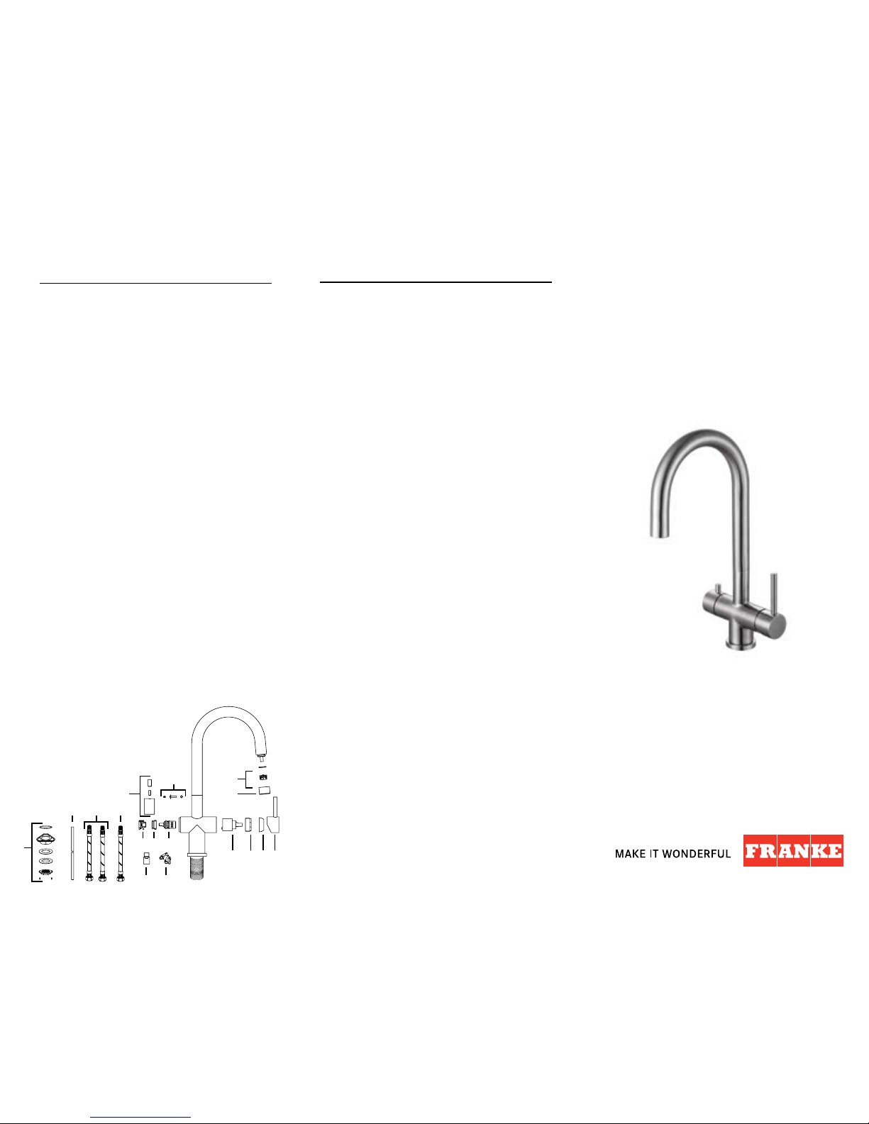
Spare/Replacement List
A. FT3301 Aerator with Washer
B. FT3302 Aerator Sleeve
C. FT3303 Mixer Handle Assembly
D. F205506 Cartridge Cap
E. F3412 Cartridge Nut
F. F206502 Cartridge
G. FT3306 Filtered Water Valve
H. FT3305 Handle Fastening Hardware
I. FT3304 Filtered Water Handle Assembly
J. FT3307 Filtered Water Connector
K. 10306 Shut-off Valve
L. 10305 Filtered Water Supply Tubing
M. F205510 Cold Water Supply Hose
N. F205509 Hot Water Supply Hose
O. FT3308 Fastening Set
O.
L. M. N.
J.
F. E. D. C.
K.
Y. X. G.
I.
B.
A.H.
I
1
H1H2H
3
I
2
I
3
Inventory #?07/2016
Page 2
TECHNICAL DATA
• Flow rate filtered water 0.52 GPM at 60 PSI
• Flow Rate mixed water 1.75 GPM at 60 PSI
• Recommended water pressure – 30-75 psi
• Max water pressure – 145 psi
• Recommended hot water temperature – 120 - 140 F
• Hole size for faucet – 1 3/8"
Certifies this faucet complies with ASME A112.18.1 / CS
B125.1 & NSF 61, NSF 372 and AB1953
Note
Contact us immediately if you see inconsistencies:
• Phone – 1-800-626-5771
• Email – ks-customerservice.us@franke.com
• Website – www.franke.us/ks.com
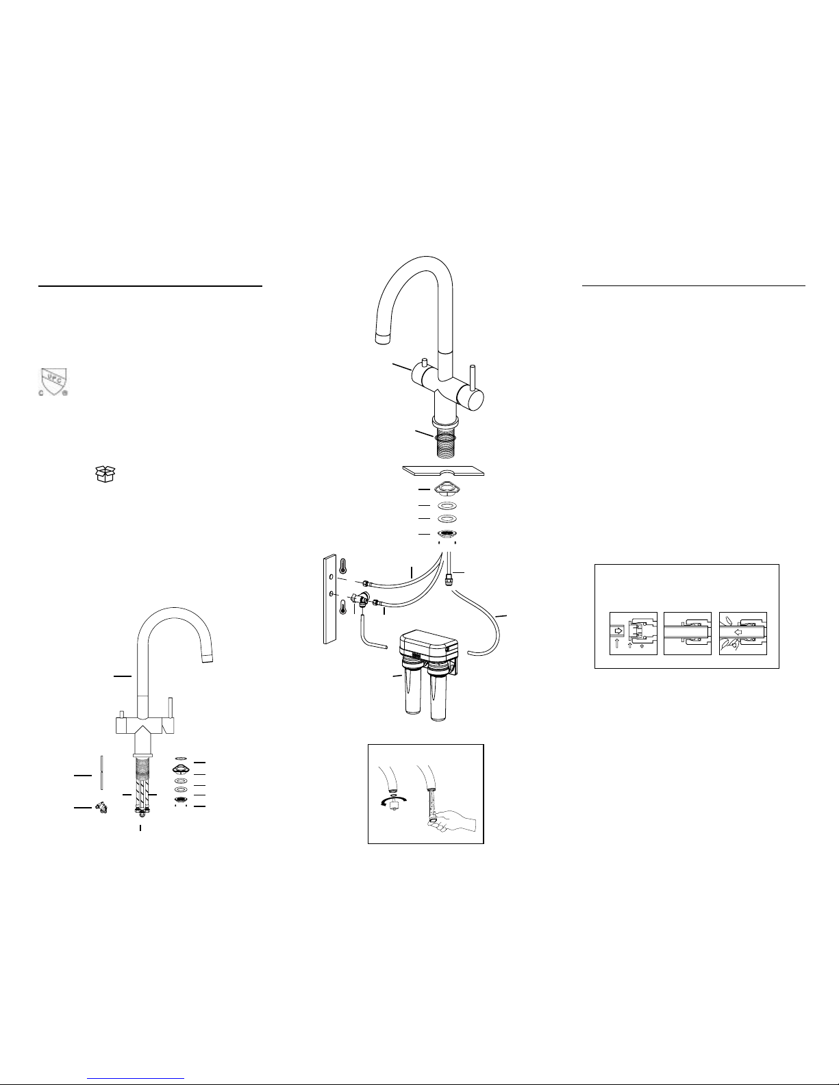
Contents in Box
A. Faucet assembly
B. Escutcheon o-ring
C. Plastic flange
D. Rubber washer
E. Steel washer
F. Fixing nut
G. Hot water supply hose
H. Filtered water supply hose with connector
I. Cold water supply hose
J. Filtered water supply tubing
K. Shut-off valve
INSTALLATION INSTRUCTIONS
1. Remove all contents from the package and check for completeness.
Franke recommends this product be installed by a licensed,
professional plumber. Be sure to observe all applicable plumbing and
building codes during the installation.
2. Turn off water supply.
3. Cut mounting hole 1
3
/8" in diameter (35mm) in the desired
position (if one isn’t available).
4. Make sure the rubber escutcheon o-ring (2) is in place in the
escutcheon. DO NOT use putty or other sealant at this location.
5. Install the mounting hardware to the base of the faucet body in the
following order: Plastic flange (3), rubber washer (4), steel washer
(5), fixing nut (6).
6. Secure the faucet by tightening the fixing nut (6) to the faucet
body by tightening the two phillips fixing screws.
7. Connect the filtered water supply tubing (9) to the filtered water
connector (8) and cut tubing to proper length to remove any
unnecessary loops or low spots. Save excess tubing for water
filtration connection.
IMPORTANT: Do NOT modify the filtered water connector
in any way, this could lead to leaks. It is pre-installed and
shouldn’t need additional tightening, but if additional
tightening is necessary, it should ONLY be tightened by
hand.
IMPORTANT: When using push fittings, ensure the ends of the
tubing are cut square and free of burrs or damage within 1” of
the end of the tube. DO NOT use any forms of sealing
compounds, or tools to remove the tubing or modify the fitting in
any way, as this can damage fitting and result in leaks. Proper
installation and removal of tubing in push fittings is outlined
below. Damage in this area can cause leaks.
8. Connect the filtered water supply tubing (9) to the exit of the
water filter (12) (sold separately).
9. Connect the hot water supply hose (7) to the hot water supply in
the house as illustrated.
10. Connect the shut-off valve (11) to the cold water supply in the
house and connect the other side to the cold water supply hose
(10) as illustrated. IMPORTANT: DO NOT over-tighten threaded
connections for the shut-off valve (11). DO NOT exceed 25
in-lbs of torque.
11. Take excess supply tubing (9) from step 7 and connect one
end to the push fitting connection of the shut-off valve (11) as
illustrated. Take the other end and connect it to the inlet of the
water filter (12).
12. Remove the aerator by hand, open shut-off valve (11) and turn on
the faucet (filtered water and then mixed water). Flush the faucet for
any debris and check for leaks. Reinstall aerator and ensure
everything is functioning properly (See fig 1).
J.
K.
Fig 1
(Not Included)
A.
I.
H.
G.
B.
C.
D.
E.
F.
1.
2.
3.
4.
5.
6.
7.
8.
9.
10.
11.
12.
Tube Collet Body
HOW TO INSERT/REMOVE TUBING
IN PUSH FIT CONNECTIONS
Insert the tubing squarely. See Figure A.
Make sure to insert tubing completely. See Figure B.
To remove, push in collet and pull out tubing. See Figure C.
Figure A Figure B Figure C
 Loading...