

Page 1
Installation and operating inst ructions Instrucciones de montaje y uso
DE
EN
FR
ES
IT
Notice de montage et de mise en service Istruzioni per il montaggio e l’uso
EA-Nr.: 7612982185335
FAR-Best.-Nr.: 2000108123
ZA3OP0011
EA-Nr.: 7612982213687
FAR-Best.-Nr.: 2030016282
ZA3OP0022
ZMI_001_2000108123-ZA3OP0011_#SALL_#AQU_#V3.fm / 10.10.17
Page 2

...................................................................................3
Please refer to the graphics in the German Installation and
Operating Instructions.
...................................................................................20
Les graphiques sont disponibles dans la notice de montage et
de mise en service allemande.
...................................................................................38
Por favor, consulte los gráficos en las instrucciones alemanas
de montaje y uso.
...................................................................................56
Per le grafiche fare riferimento alle Istruzioni per il montaggio
e l’uso in tedesco.
EN
FR
ES
IT
Inhaltsverzeichnis35-31.fm
2
Page 3

0English
EN
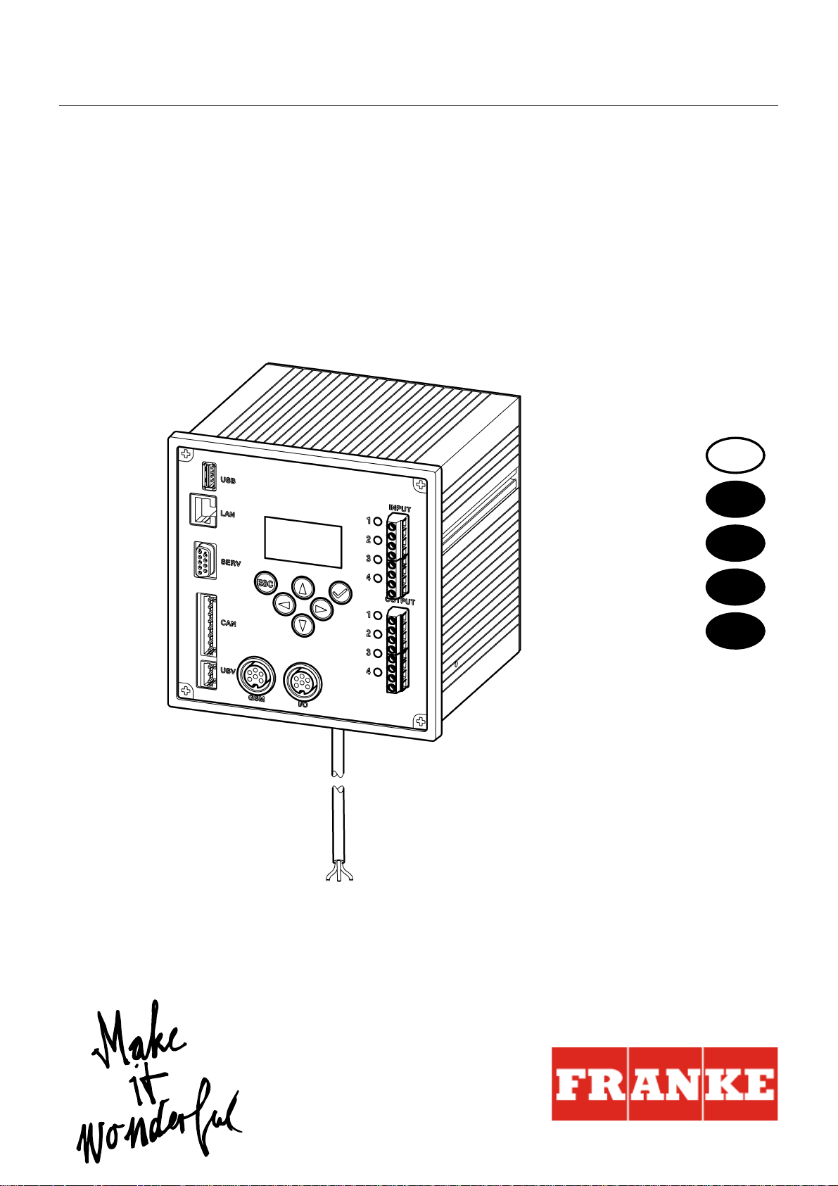
ECC2 Function Controller - A3000 open with
Ethernet Connection, 230 V AC / 24 V DC
2000108123
2030016282 .......................... including BMS data protocols
Please refer to the graphics in the German Installation and Operating Instructions.
Contents
1. Abbreviations and Units . . . . . . . . . . . . . . . . . . . . . . . . . . . . . . . . 4
2. Key . . . . . . . . . . . . . . . . . . . . . . . . . . . . . . . . . . . . . . . . . . . . . . . . 4
3. Warranty . . . . . . . . . . . . . . . . . . . . . . . . . . . . . . . . . . . . . . . . . . . . 4
4. Important Notes . . . . . . . . . . . . . . . . . . . . . . . . . . . . . . . . . . . . . . 4
Description of Product
5. Application . . . . . . . . . . . . . . . . . . . . . . . . . . . . . . . . . . . . . . . . . . 5
6. Technical Specifications . . . . . . . . . . . . . . . . . . . . . . . . . . . . . . . . 6
7. Special Features. . . . . . . . . . . . . . . . . . . . . . . . . . . . . . . . . . . . . . 7
8. Dimensions. . . . . . . . . . . . . . . . . . . . . . . . . . . . . . . . . . . . . . . . . . 7
9. Connections . . . . . . . . . . . . . . . . . . . . . . . . . . . . . . . . . . . . . . . . . 7
10. Pin Configurations . . . . . . . . . . . . . . . . . . . . . . . . . . . . . . . . . . . . 8
Installation, Function and Commissioning
11. Assembly Instructions. . . . . . . . . . . . . . . . . . . . . . . . . . . . . . . . . . 10
12. Display with Menu Keys . . . . . . . . . . . . . . . . . . . . . . . . . . . . . . . . 11
13. Permissions / Passwords . . . . . . . . . . . . . . . . . . . . . . . . . . . . . . . 12
14. Display for Staff Level. . . . . . . . . . . . . . . . . . . . . . . . . . . . . . . . . . 13
15. Settings in Technician Level . . . . . . . . . . . . . . . . . . . . . . . . . . . . . 14
16. Start Web Application . . . . . . . . . . . . . . . . . . . . . . . . . . . . . . . . . . 16
17. Connection Example . . . . . . . . . . . . . . . . . . . . . . . . . . . . . . . . . . 17
18. UPS . . . . . . . . . . . . . . . . . . . . . . . . . . . . . . . . . . . . . . . . . . . . . . . 17
Maintenance
19. Fault Correction . . . . . . . . . . . . . . . . . . . . . . . . . . . . . . . . . . . . . . 17
20. Accessories . . . . . . . . . . . . . . . . . . . . . . . . . . . . . . . . . . . . . . . . . 17
21. Error Code . . . . . . . . . . . . . . . . . . . . . . . . . . . . . . . . . . . . . . . . . . 18
ZMI_001_2000108123-ZA3OP0011_#SEN_#AQU_#V3.fm
- 3 -
Page 4
1. Abbreviations and Units
EMC Electromagnetic compatibility
RCD Residual Current Protective Device,
SELV Safety Extra Low Voltage
UPS Uninterruptible power supply
EA No. European Article Number
FAR Order No. Franke Aquarotter Order Number
Conversion 1 mm = 0.03937 inches
All length specifications in the graphics are in mm.
Earth leakage circuit breaker
1 inch = 25.4 mm
2. Key
Warning!
Failure to observe can result in injury or even death.
Caution!
Failure to observe can result in material damage.
☞ Important!
Failure to observe can cause the product to malfunction.
☞ Useful information for optimally handling the product.
3. Warranty
Liability is accepted according to the General Terms and Conditions of Business and
Supply.
Use original replacement parts only!
4. Important Notes
• Installation, commissioning and maintenance are to be performed only by a
qualified technician according to the instructions provided and in accordance with
legal requirements and acknowledged rules of technology.
• All technical connection regulations specified by the local water and electricity
supply utility companies must be complied with.
• All work must be carried out in a de-energised state.
- 4 -
ZMI_001_2000108123-ZA3OP0011_#SEN_#AQU_#V3.fm
Page 5

• Because of the IP20 protective system used, the device must be operated in dry
rooms only.
• Only appliances with protection class III (SELV) may be connected to the unit.
• During the warranty period, the factory-set output voltage 24V may only be
changed by the Franke-Aquarotter customer service department.
• Secure the electric connection with an earth leakage circuit breaker (RCD).
• Proper cooling must be assured. To ensure an unimpeded flow of cooling air, it is
important to maintain a minimum distance of 15 mm to adjacent equipment.
• All rights reserved to make technical alterations.
5. Application
ECC2 Function Controller - A3000 open with Ethernet and CAN bus connection. For
connecting AQUA 3000 open fittings/electronic system modules for the purpose of
supplying power and external control, such as settings for fittings and communication. For mounting on a 35 mm DIN rail in the on-site switch-gear cabinet
(provided by customer), for wall mounting or in an electrical distribution system in
accordance with the applicable VDE regulations.
Functions of integrated digital inputs with LED status display:
– Control for thermal disinfection
– Acknowledgment of collective fault signals
– Switching program modes (e.g. night mode or holiday mode)
Functions of the integrated potential-free digital outputs with LED status display:
– Control for thermal disinfection
– Display of collective fault signals
Storage of statistical data with date and time, can be read via the USB interface in
csv format.
Additional functions can be set via a web browser:
– Switch-off for cleaning
– Triggering hygiene flushing
– Simultaneity suppression
– Sequential controls
– System flushing
– Reduction in flow duration
ZMI_001_2000108123-ZA3OP0011_#SEN_#AQU_#V3.fm
- 5 -
Page 6

6. Technical Specifications
Product group: Primary switched-mode voltage regulator (single
EMC: EN 61000-6-3 (electromagnetic emission)
Electrical safety: EN 60950
Protective system IP 20
Protection class: I
Test voltage: 4.2 kV DC
Dimensions (W x H x D): 144 × 144 × 151 mm
Ambient temperature: -10°C to 60°C / 70°C for 10 min
Cooling: Natural convection
Humidity: 100% relative humidity
phase, primary switched built-in power supply with
Ethernet-CAN coupler)
EN 61000-6-2 (electromagnetic immunity)
There must be no dew formation when the system is
to be commissioned.
Storage temp.: -40°C to 80°C
Long-term storage: To maintain the condensers, apply mains voltage to
the device for at least 5 min. every two years.
Input
Input AC: Rated voltage 100 – 240 V AC / 50 – 60 Hz
Rated current: 0.6 A at 230 V AC
Overvoltage protection: Varistor in the input circuit
Connections: 3 x 1.5 mm²
Output
Output DC (SELV): Rated voltage 24 V DC
Range 22 – 28 V (preset to 24 V)
Rated current: 2.5 A at 24 V DC
Ripple: 150 mVpp (at 20 MHz)
Efficiency: 89 %
Current limitation: from 1.1 × I
Rated
Connections: WAGO 734 Series multi-connector system for max.
1.5 mm²
Digital connections
Connection facilities: Ethernet, USB 2.0, UPS
Connections: WAGO 734 Series multi-connector system for max.
1.5 mm²
- 6 -
ZMI_001_2000108123-ZA3OP0011_#SEN_#AQU_#V3.fm
Page 7

7. Special Features
• Wide range input for AC
• Maintenance free
• Open-circuit proof
• Short-circuit proof
• Protected both on the inside as well as the outside by an internal fuse
• Protected on the outside by an electronic voltage/current controller
• Output voltage adjustable
• in parallel with factory-set default output voltage of 24 V
☞ During the warranty period, the factory-set output voltage 24 V may only be altered
by the customer service department.
• Monitoring by means of an integrated Ethernet-CAN module
• Facility for connecting a UPS
• USB port for offline data transfer to a PC, RJ45 connector for 10/100 Mbit
Standard Ethernet for PC or building network
• Interfaces for optional expansion module (I/O) and wireless module (GSM)
• BMS (building management system) connection possible using protocols BacNet
- IP, KNX - IP and Modbus - TCP
• Visualization and parametrization of the fittings network via integrated display or
web browser
8. Dimensions
9. Connections
1 Port for USB stick (for updates and storing statistical data)
2 RJ45 interface for data communication
(LAN and BMS)
3 Service interface RS232
4 Connection for system lines (operating voltage and CAN bus system; max. 32 fittings)
5 Connector for UPS power supply (optional)
6 Connector for wireless module (optional)
7 Connector for expansion module (optional)
8 Power supply connection
9 Connections for inputs and outputs (supplementary functions)
10 Display with menu buttons (siehe Kapitel 12.)
ZMI_001_2000108123-ZA3OP0011_#SEN_#AQU_#V3.fm
- 7 -
Page 8

Inputs
Input 1 ... Thermal disinfection
Input 2 ... Abort thermal disinfection
Input 3 ... Acknowledge outputs
Input 4 ... Switching program modes
Outputs
Output 1 ... Thermal disinfection active
Output 2 ... Thermal disinfection
Abort (manual)
Output 3 ... Thermal disinfection
Safety abort
Output 4 ... Collective fault message
RD ... red
BU ... blue
WH ... white
BK ... black
10. Pin Configurations
SELV power supply and data bus (cable system)
Pin Signal Level Color Function
1 Data-L ±0.2 V DC to
BK
±5 V DC
Data bus for bus isle
2 Data-H ±0.2 V DC to
WH
±5 V DC
3 GND 0 V DC BU Reference for bus isle
looped through
4 24 V 24 V DC RD Supply voltage for bus
isle looped through
5 Data-L ±0.2 V DC to
BK
±5 V DC
Data bus for bus isle
6 Data-H ±0.2 V DC to
WH
±5 V DC
7 GND 0 V DC BU Reference for bus isle
looped through
8 24 V 24 V DC RD Supply voltage for bus
isle looped through
- 8 -
ZMI_001_2000108123-ZA3OP0011_#SEN_#AQU_#V3.fm
Page 9

UPS (battery module)
Pin Signal Level Current Function
1 UPS LOW UPS plugged on
HIGH no UPS plugged on
2 GND Reference
3 24 V 24 V DC 2.5 A Supply voltage for bus isle
looped through
Factory settings:
Digital inputs IN1 through IN4 (Input) and
digital outputs OUT1 through OUT2 (Output)
Input 1 - Function:
Start command for thermal disinfection
☞ The contact must be closed at least 5s and no more than 2 minutes
Input 2 - Function:
Abort thermal disinfection
☞ This is triggered with a pulse.
• Thermal disinfection is stopped.
• A safety window of at least 30s passes before the fittings are flushed, and the
system then returns to its normal mode of operation. This process is then
recorded as being "not successful".
• The fittings start the cooling phase.
Input 3 - Function:
Acknowledgment for outputs
☞ This is triggered with a pulse.
• All digital outputs are reset.
Input 4 - Function:
Switching program modes
example for: summer/winter mode, day/night mode or room occupied/not occupied.
☞ The input can be connected with a switch, time switch or GLT contact.
• Functionality depends on the contents of the program ID within the electronic
module.
ZMI_001_2000108123-ZA3OP0011_#SEN_#AQU_#V3.fm
- 9 -
Page 10

Output 1 - Function:
Relay contact 48 VDC/1 A and 240 V AC/2 A
Assigned to thermal disinfection.
☞ Normal functionality: Permanently "ON" for the duration of the thermal disin-
fection process
• Acknowledgement see IN3
Output 2 - Function:
Relay contact 48 VDC/1 A and 240 V AC/2 A
Assigned to thermal disinfection.
☞ Normal functionality: Permanently "ON" when thermal disinfection was aborted
manually.
• Acknowledgement see IN3
Output 3 - Function:
Relay contact 48 VDC/1 A and 240 V AC/2 A
Assigned to thermal disinfection.
☞ Normal functionality: Permanently "ON" when thermal disinfection was aborted
by the system.
• Acknowledgement see IN3
Output 4 - Function:
Relay contact 48 V DC/1 A and 240 V AC/2 A
Assigned to collective fault messaging.
☞ Normal functionality: Permanently "ON" when a fault message is being waved.
• Acknowledgement see IN3
11. Assembly Instructions
☞ When installing several devices, it is essential to ensure an unimpeded flow of
cooling air by maintaining a minimum distance of 15 mm to adjacent parts.
☞ Mount the ECC2 function controller (1) on a rail.
11.1
Snap-lock the lower edge (3) into the rail.
11.2
Push up the ECC2 function controller.
11.3
Snap-lock the upper edge (2) into the rail.
11.4
Connect the system cable (4).
Connecting input and output cables (5)
☞ The maximum cross section of an input/output cable is 1.5 mm².
11.5
Strip off 8 mm of the ends of the input/output cables.
☞ Apply wire-end ferrules to flexible electric cables.
11.6
Connect the input/output cables according to the pin configuration (siehe Kapitel 9.).
- 10 -
ZMI_001_2000108123-ZA3OP0011_#SEN_#AQU_#V3.fm
Page 11
11.7
Connect the desired optional equipment.
11.8
Connect the power cord.
• After the operating voltage has been switched on, the display shows the startup
screen
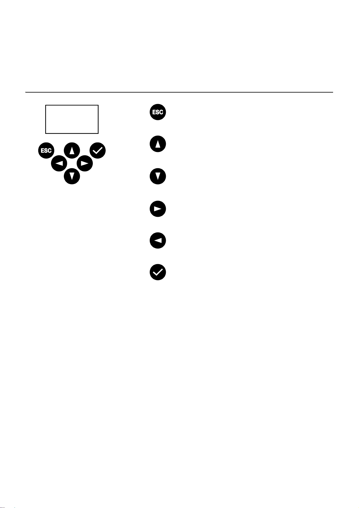
12. Display with Menu Keys
Escape - Aborts each control process and/
or returns to the previous menu level
Cursor up - Navigates upwards line by line
in the menu
Cursor down - Navigates downwards line
by line in the menu
Cursor right - Navigates to the right in the
menu
Cursor left - Navigates to the left in the
menu
Enter - Accepts a value and/or continues
one menu level further
ZMI_001_2000108123-ZA3OP0011_#SEN_#AQU_#V3.fm
- 11 -
Page 12
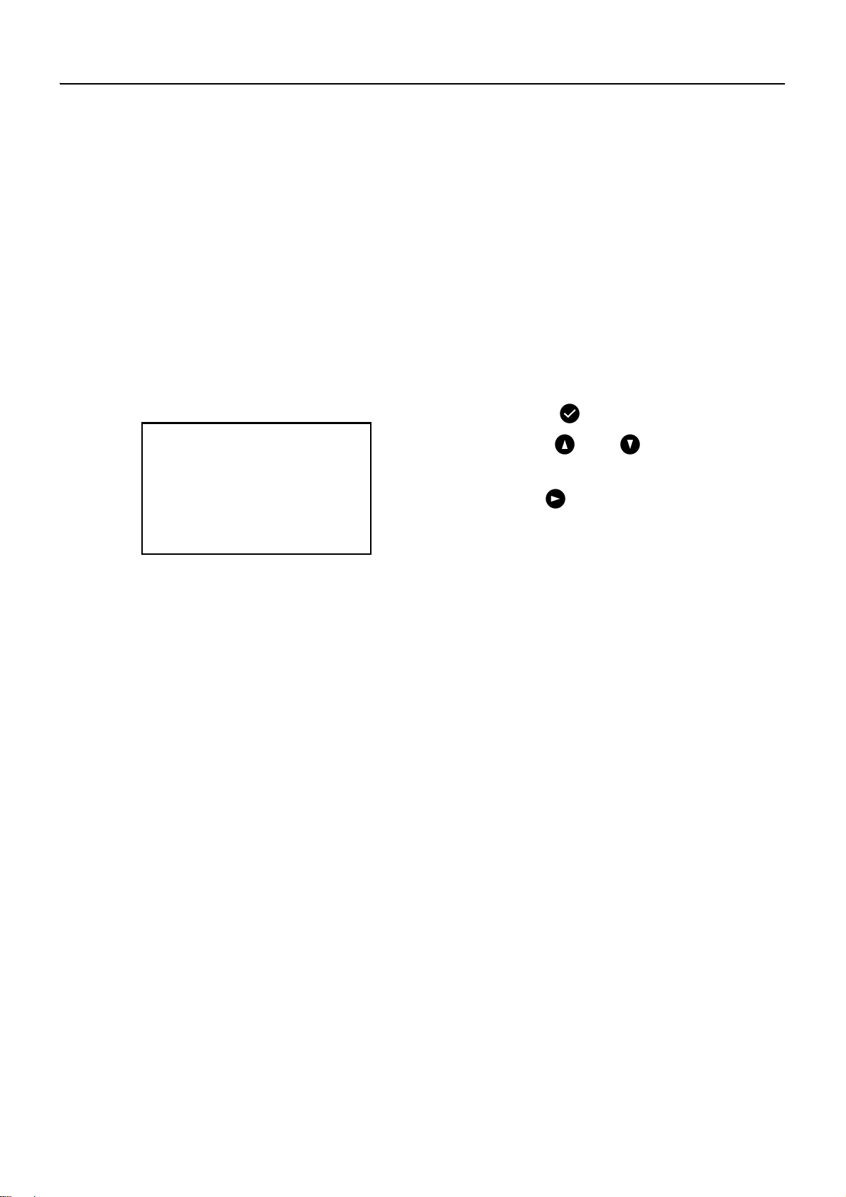
13. Permissions / Passwords
PIN
0 0 0 0 0
Permission Level
Different permission levels are available for viewing and changing operating
parameters within the multi-function power supply control:
Staff Level No password needed, just for viewing some
parameters
Technician Level Customer/Operator password - Changing all
permissions, saving, etc.
The password consist of a 5-digit numerical code.
Entering passwords (PIN)
13.1
Press key .
13.2
Use keys and to enter the
required digit.
13.3
Use key to jump to the next
location.
☞ When the PIN has been entered successfully the display will show the main menu.
When a wrong number is confirmed with the enter key, the display will remain in
the 'Enter PIN:' status.
Resetting a Permission Level
The permission level must be reset when, for example, the control system must be
immediately protected against unauthorized use after service work was done in the
Technician Level.
☞ If no entries are made in the control panel for more than 4 min., the permission level
is automatically reset.
ZMI_001_2000108123-ZA3OP0011_#SEN_#AQU_#V3.fm
- 12 -
Page 13
14. Display for Staff Level
ECC2 ECC-Name
22/01/2013
14:21
Menu
Page 1
Modules
Fittings
8/10
Page 2 Voltage
24.63V
Page 3 Fault (9)
22.01.2013 13:43 1000
22.01.2013 13:39 1
22.01.2013 13:36 1
21.01.2013 07:50 1
18.01.2013 08:52 1
Page 4 Version
Version x.xx
Page 5 Static IP
IP 10.222.48.226
NM 255.255.0.0
GW 10.222.0.50
DNS
MAC 00-04-A3-87-3D-B5
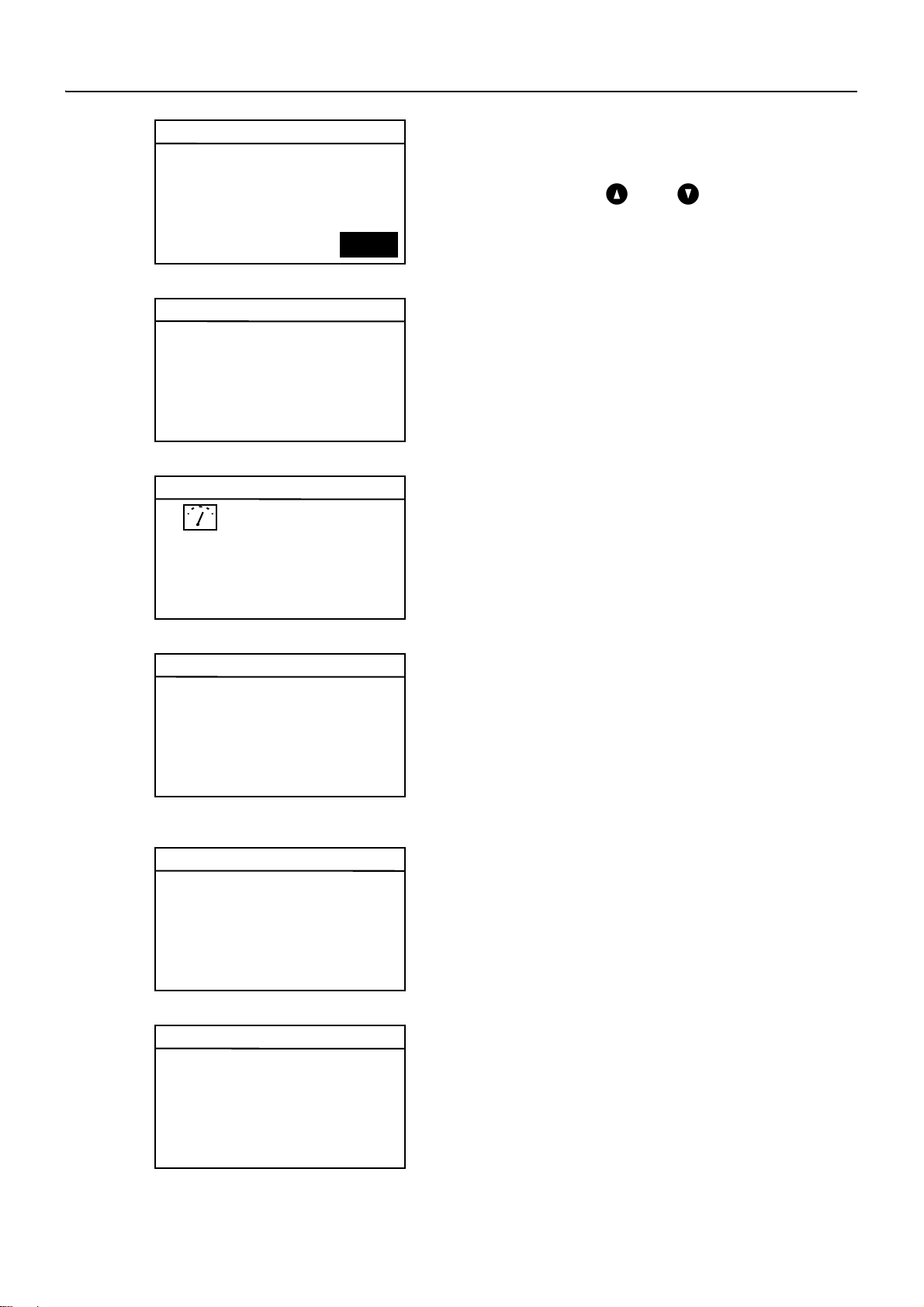
After the operating voltage has been
switched on, the display shows the startup
screen.
14.1
Use keys and to set the
required page.
Page 1
Shows how many fittings are
connected and in operation.
e.g.: 8 of 10 connected fittings are in
operation
Page 2
Displays the operating voltage for the
valves.
Page 3
Displays
– how many error messages are
stored.
– The last 5 error messages with
date, time and error code
(siehe Kapitel 21.).
Page 4
Shows which version of the system
software is installed on the ECC2
function controller.
Page 5
Shows which device IDs and network
IDs the ECC2 function controller has.
ZMI_001_2000108123-ZA3OP0011_#SEN_#AQU_#V3.fm
- 13 -
Page 14
15. Settings in Technician Level
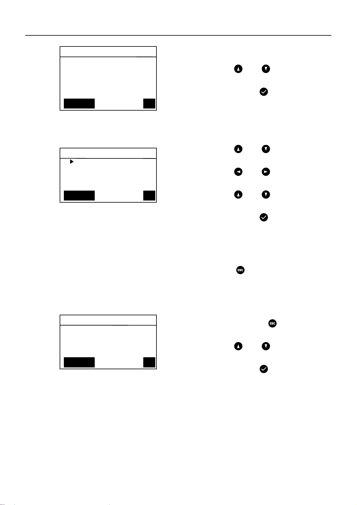
Main menu
Network config.
Date/time format
Set date/time
Temperature
Restart
OKCancel
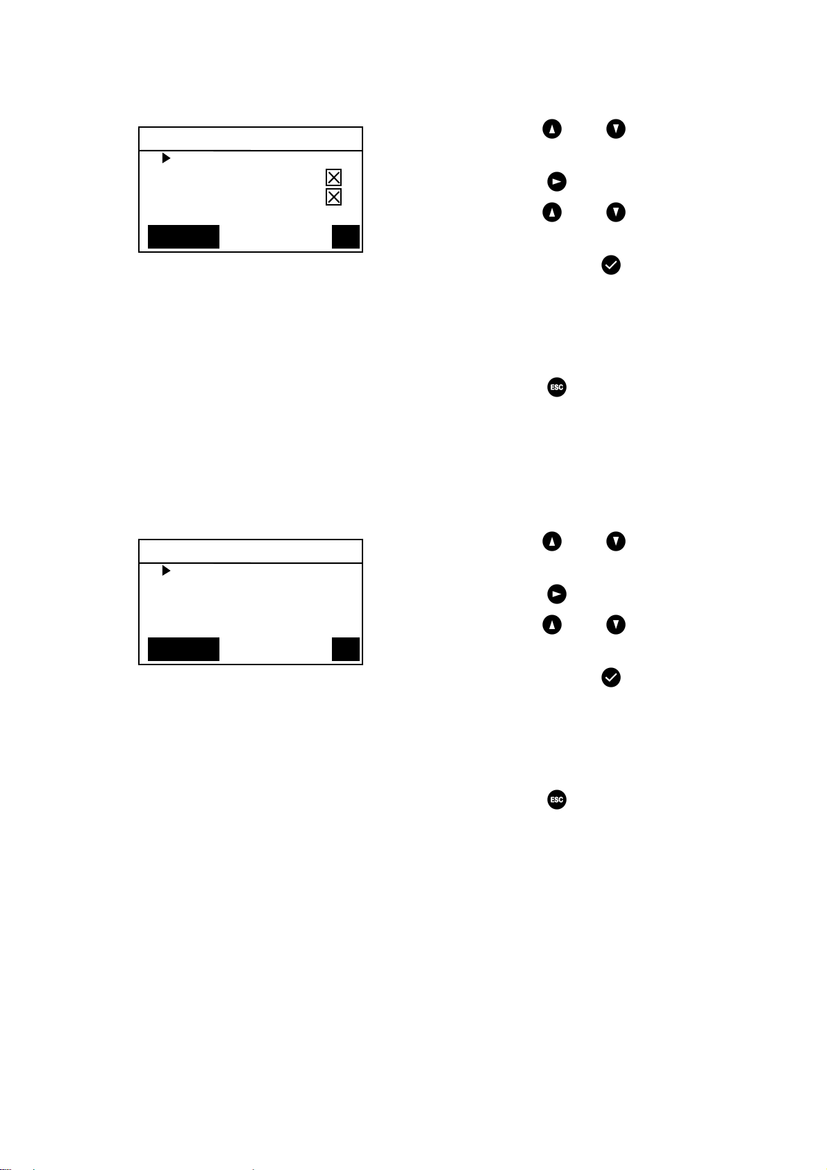
Network configuration
IP 010.222.048.222
NM 255.000.000.000
GW 010.222.000.050
DNS 255.000.000.000
OKAbort
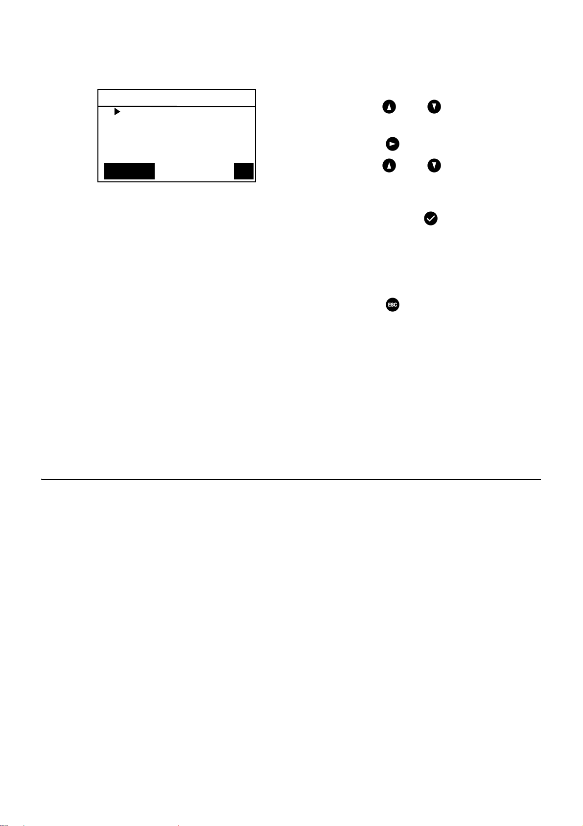
select language
Deutsch
Englisch
čeština
Dansk
OKCANCEL
15.1
Enter the PIN (siehe Kapitel 13.).
• The main menu appears.
15.2
Use keys and to select the
desired menu.
15.3
Confirm with key .
• The desired menu opens up.
Network configuration
15.4
Select the "Network Config." menu.
15.5
Use keys and to select the
desired number.
15.6
Use keys and to select the
desired number block.
15.7
Use keys and to enter the
desired number.
15.8
Confirm with key .
• The entries are saved.
• The main menu opens.
or
Press key .
• The entries are not saved.
• The main menu opens.
Select language
15.9
Press and hold key approx. 3
seconds.
15.10
Use keys and to enter the
desired language.
15.11
Confirm with key .
ZMI_001_2000108123-ZA3OP0011_#SEN_#AQU_#V3.fm
- 14 -
Page 15
Date/time formats
Date/time formats
Date DD.MM.YYYY
24H format
Summer time
OKCancel
Set Date/Time
Date 21.01.2013
Time 15:2
1
OKAbort
15.12
Select the "Date/Time" format menu.
15.13
Use keys and to select the
desired format.
15.14
Press key .
15.15
Use keys and to set the
desired format.
15.16
Confirm with key .
• The entries are saved.
• The main menu opens.
or
Press key .
• The entries are not saved.
• The main menu opens.
Set Date/Time
15.17
Select the "Set Date/Time" menu.
15.18
Use keys and to select
between date and time.
15.19
Press key .
15.20
Use keys and to set the
desired date and time.
15.21
Confirm with key .
• The entries are saved.
• The main menu opens.
or
Press key .
• The entries are not saved.
• The main menu opens.
ZMI_001_2000108123-ZA3OP0011_#SEN_#AQU_#V3.fm
- 15 -
Page 16
Temperature/Unit (for electronic group
Temperature/Unit
°C/°F °C
Mixer 1 65.0°C
Mixer 2 65.0°C
Mixer 3 65.0°C
OKAbort
thermostat)
15.22
Select the "Temperature" menu.
15.23
Use keys and to select the
units or the desired mixer.
15.24
Press key .
15.25
Use keys and to set the
desired unit or the desired temperature.
15.26
Confirm with key .
• The entries are saved.
• The main menu opens.
or
Press key .
• The entries are not saved.
• The main menu opens.
Restart ECC2 function controller
15.27
Select the "Restart" menu.
• The ECC2 function controller is
restarted.
16. Start Web Application
16.1
Start a PC in the network.
16.2
Select an Internet browser.
16.3
Enter the IP of the ECC2 function controller in the address bar of the Internet
browser.
16.4
Enter the User and Password.
16.5
Click the "Login" button.
☞ A guide for the Web application is provided in the "Help" menu.
- 16 -
ZMI_001_2000108123-ZA3OP0011_#SEN_#AQU_#V3.fm
Page 17
17. Connection Example
Accessories Order No.
Wireless module . . . . . . . . . . . . . . . . 2000108125
Rod antenna . . . . . . . . . . . . . . . . . . . 2000110895
Wall antenna . . . . . . . . . . . . . . . . . . . 2000110896
Active antenna . . . . . . . . . . . . . . . . . 2000110897
Expansion module . . . . . . . . . . . . . . 2000108124
UPS power supply . . . . . . . . . . . . . . 2000100977
A: max. 200 m system cable or max. 32 fittings with a total performance of max. 60 W
B: Ethernet
C: Terminating resistor
D: Mains 250 V AC
Lead power cord via main switch or fuse
RD ... red
BU ... blue
WH ... white
BK ... black
18. UPS
The ECC function controller automatically detects the presence of any connected
UPS. The UPS is then checked every 25 hours. The ECC checks the function of the
UPS by switching off its own supply voltage for 5 seconds. The system then
operates with power from the UPS. During this time the ECC function controller
measures the voltage. If the voltage is less than 22 V, a corresponding message is
displayed.
19. Fault Correction
Fault Cause Remedy
No output voltage is
present, the display
– Voltage supply interrupted ➯ Restore it
– ECC2 function controller defective ➯ Replace it
does not light
If you are unable to correct a fault or if the fault is not described in the fault correction
section, please inform our customer service department!
20. Accessories
ZMI_001_2000108123-ZA3OP0011_#SEN_#AQU_#V3.fm
- 17 -
Page 18

21. Error Code
Code Meaning
1 System was started
2 System is being shut down.
3Start TD
4 TD completed successfully
5 TD was terminated after an error
100 Start TD Phase 1
110 TD Phase 1 not confirmed by all modules
200 Start TD Phase 2
210 TD Phase 2 not confirmed by all tank modules
211 TD Phase 2 aborted after timeout
300 Start TD Phase 3
310 Rapid heating not confirmed by all EMs
311 TD Phase 3 aborted after timeout
312 TD Phase 3 not confirmed by all masters
313 Rapid heating could not be stopped
400 Start TD Phase 4
410 TD Phase 4 not confirmed by all master modules
411 Master reports safety switch-off
450 Master reports completion (log with temperature)
451 EM reports quick heating terminated
500 Start TD Phase 5 (however only group starts are logged)
501 TD Phase 5 Group 1 started
502 TD Phase 5 Group 2 started
503 TD Phase 5 Group 3 started
504 TD Phase 5 Group 4 started
505 TD Phase 5 Group 5 started
506 TD Phase 5 Group 6 started
507 TD Phase 5 Group 7 started
508 TD Phase 5 Group 8 started
509 TD Phase 5 Reheating time
510 TD Phase 5 not confirmed by all EMs of the group
511 TD Phase 5 aborted after timeout in the group
512 TD Phase 5 tank stop not confirmed
550 TD Phase 5 tank stop started
600 Start TD Phase 6
601 TD Phase 6 Group 1 started
Code Meaning
- 18 -
ZMI_001_2000108123-ZA3OP0011_#SEN_#AQU_#V3.fm
Page 19

602 TD Phase 6 Group 2 started
603 TD Phase 6 Group 3 started
604 TD Phase 6 Group 4 started
605 TD Phase 6 Group 5 started
606 TD Phase 6 Group 6 started
607 TD Phase 6 Group 7 started
608 TD Phase 6 Group 8 started
610 Master has not confirmed Phase 6
611 EMs in current group have not been confirmed Phase 6
620 TD Phase 6 started because of abort
650 TD Phase 6 Cooling of the TD master modules confirmed
651 TD Phase 6 Cooling terminated after safety window
700 TD Phase 7 started (return to normal operation)
710 TD Phase 7 Normal operation not confirmed by all modules
1000 CAN bus error
1001 CAN bus OK
1002 Leakage detected
2036 CAN bus error
2037 Opto-sensor missing
2041 Solenoid valve 1 cable broken
2042 Solenoid valve 1 short circuit
2044 Solenoid valve 2 cable broken
2045 Solenoid valve 2 short circuit
2047 Undervoltage
2061 Temperature sensor 1 cable broken
2062 Temperature sensor 2 cable broken
2068 Opto-sensor missing
2069 Temperature sensor 1 short circuit
2070 Temperature sensor 2 short circuit
2073 Opto-sensor missing
4000 EM not sending data
4001 EM has commenced sending data again
ZMI_001_2000108123-ZA3OP0011_#SEN_#AQU_#V3.fm
- 19 -
Page 20

0Français
FR
Contrôleur de fonctions ECC2 - A3000 ouvert avec
connexion Ethernet, 230 V CA / 24 V CC
2000108123
2030016282 .......................... Protocoles de données inclus
Les graphiques sont disponibles dans la notice de montage et de mise en service
allemande.
Sommaire
1. Abréviations et unités . . . . . . . . . . . . . . . . . . . . . . . . . . . . . . . . . . 21
2. Explication des symboles . . . . . . . . . . . . . . . . . . . . . . . . . . . . . . . 21
3. Garantie . . . . . . . . . . . . . . . . . . . . . . . . . . . . . . . . . . . . . . . . . . . . 21
4. Remarques importantes . . . . . . . . . . . . . . . . . . . . . . . . . . . . . . . . 22
Description du produit
5. Application . . . . . . . . . . . . . . . . . . . . . . . . . . . . . . . . . . . . . . . . . . 22
6. Données techniques. . . . . . . . . . . . . . . . . . . . . . . . . . . . . . . . . . . 23
7. Caractéristiques principales . . . . . . . . . . . . . . . . . . . . . . . . . . . . . 24
8. Dimensions. . . . . . . . . . . . . . . . . . . . . . . . . . . . . . . . . . . . . . . . . . 25
9. Raccordements . . . . . . . . . . . . . . . . . . . . . . . . . . . . . . . . . . . . . . 25
10. Affectation des raccords . . . . . . . . . . . . . . . . . . . . . . . . . . . . . . . . 26
Montage, fonctionnement et mise en service
11. Montage . . . . . . . . . . . . . . . . . . . . . . . . . . . . . . . . . . . . . . . . . . . . 28
12. Écran avec des touches de menu . . . . . . . . . . . . . . . . . . . . . . . . 29
13. Autorisations/mots de passe. . . . . . . . . . . . . . . . . . . . . . . . . . . . . 30
14. Affichage niveau Personnel . . . . . . . . . . . . . . . . . . . . . . . . . . . . . 31
15. Paramètres du niveau Technicien . . . . . . . . . . . . . . . . . . . . . . . . 32
16. Lancer l'appliquant Internet . . . . . . . . . . . . . . . . . . . . . . . . . . . . . 34
17. Exemple de raccordement . . . . . . . . . . . . . . . . . . . . . . . . . . . . . . 35
18. ASI . . . . . . . . . . . . . . . . . . . . . . . . . . . . . . . . . . . . . . . . . . . . . . . . 35
Entretien
19. Élimination de pannes . . . . . . . . . . . . . . . . . . . . . . . . . . . . . . . . . 35
20. Accessoires . . . . . . . . . . . . . . . . . . . . . . . . . . . . . . . . . . . . . . . . . 35
21. Code d'erreur . . . . . . . . . . . . . . . . . . . . . . . . . . . . . . . . . . . . . . . . 36
ZMI_001_2000108123-ZA3OP0011_#SFR_#AQU_#V3.fm
- 20 -
Page 21
1. Abréviations et unités
CEM Compatibilité électromagnétique
RCD Residual Current Protective Device,
SELV Safety Extra Low Voltage, basse tension de
ASI Alimentation continue en courant
N° EA Numéro d’article européen
N° de comm. FAR Numéro de commande Franke Aquarotter
Conversion 1 mm = 0,03937 pouce
Interrupteur de protection contre les courants de
court-circuit
protection
1 pouce = 25,4 mm
Dans les graphiques, toutes les longueurs sont indiquées en mm.
2. Explication des symboles
Avertissement !
Le non-respect des consignes est susceptible d'induire un danger de mort ou de
provoquer des blessures corporelles.
Attention !
Le non-respect des consignes est susceptible de provoquer des dommages
matériels.
☞ Important !
Le non-respect des consignes est susceptible de provoquer des dysfonctionnements du produit.
☞ Informations utiles pour une utilisation optimale du produit.
3. Garantie
La responsabilité est assumée conformément aux conditions générales de vente et
de livraison.
Utiliser uniquement des pièces de rechange d’origine !
ZMI_001_2000108123-ZA3OP0011_#SFR_#AQU_#V3.fm
- 21 -
Page 22

4. Remarques importantes
• Seul un spécialiste est habilité à effectuer le montage, la mise en service et
l’entretien de l’installation, ces opérations étant effectuées selon les instructions
fournies, conformément aux prescriptions légales et aux règles techniques
reconnues.
• Il convient de respecter les conditions techniques de raccordement des entreprises locales de distribution d’eau et d’énergie.
• Effectuez tous les travaux quand le dispositif est hors tension.
• En raison du type de protection IP 20, le fonctionnement de l’appareil ne doit avoir
lieu que dans des lieux secs.
• Seuls des moyens d’exploitation de la classe de protection III (SELV) peuvent être
raccordés à l’appareil.
• Lors de la période de garantie, la tension de sortie réglée en usine de 24 V ne
peut être modifiée que par le service après-vente clientèle.
• Protéger le raccordement électrique avec un interrupteur de protection contre les
courants de court-circuit (RCD).
• Garantir le refroidissement. Veiller à ce que l’amenée d’air ne soit pas bouchée et
respecter un écart minimal de 15 mm avec les pièces jouxtant l’appareil.
• Sous réserve de modifications.
5. Application
Contrôleur de fonctions ECC2 - A3000 ouvert avec connexion ethernet et bus CAN.
Destiné au raccordement des robinetteries/modules électroniques système AQUA
3000 open pour alimentation en tension et commande externe, comme le réglage
des robinets et la communication. Pour le montage sur un rail normé de 35 mm dans
l'armoire électrique du client, dans un tableau électrique ou dans un distributeur
électrique conformément aux règlements VDE (Association des Électrotechniciens
Allemands).
Fonctions des entrées numériques intégrées avec indication d'état LED :
– Commande d'une désinfection thermique
– Validation de messages d'erreur regroupés
– Commutation des modes de programmes (p. ex. commutation nocturne ou de
vacances)
Fonctions des sorties numériques intégrées sans potentiel avec indication d'état
LED :
– Commande d'une désinfection thermique
– Affichage de messages d'erreur regroupés
- 22 -
ZMI_001_2000108123-ZA3OP0011_#SFR_#AQU_#V3.fm
Page 23

Enregistrement de données statistiques avec date et heure qui peuvent être
appelées en format CSV par voie de l'interface USB.
Fonctions supplémentaires paramétrables moyennant le navigateur Internet :
– Désactivation pour le nettoyage
– Déclenchement de rinçages hygiéniques
– Suppression simultanée
– commandes séquentielles
– Rinçage de l’installation
– Réduction de la durée d'écoulement
6. Données techniques
Groupe de produit : Régulateur à commutation primaire (monophasé,
alimentation intégrée à cycle primaire avec coupleur
Ethernet-CAN)
CEM : EN 61000-6-3 (émissions parasites)
EN 61000-6-3 (résistance aux interférences)
Sécurité électrique : EN60950
Type de protection IP 20
Classe de protection : I
Tension de contrôle : 4,2 kV CC
Dimensions L × H × P : 144×144×151 mm
Température ambiante : -10°C à +60°C / 70°C pour 10 min
Refroidissement : Convection naturelle
Humidité de l’air : 100% humidité relative
Pas de rosée lors de la mise en service.
Température de
-40°C à +80°C
stockage :
Stockage prolongé : Pour le maintien des condensateurs sur l’appareil,
appliquer une tension réseau pendant 5 minutes au
moins tous les deux ans.
Entrée
Entrée CA : Tension de référence 100 – 240 V CA, 50 – 60 Hz
Courant de référence : 0,6 A / 230 V CA
Protection contre les
Varistor dans le circuit d’entrée
surtensions :
Raccords : 3 ×1,5 mm²
ZMI_001_2000108123-ZA3OP0011_#SFR_#AQU_#V3.fm
- 23 -
Page 24

Sortie
Sortie CC (SELV) : Courant de référence 24 V CC
Fourchette 22 – 28 V (préréglage à 24 V)
Courant de référence : 2,5 A à 24 V CC
Ondulation : 150 mVpp (à 20 MHz)
Rendement : 89%
Limitation de courant : à partir de 1,1 × I
Raccords :
Raccordements
numériques
Possibilités de raccordement :
Raccords : Système multifiches WAGO série 734 pour max. 1,5
Système multifiches WAGO série 734 pour max. 1,5 mm²
Ethernet, USB 2.0, USV
mm²
7. Caractéristiques principales
• Large entrée pour courant alternatif
• Sans entretien
• Résiste à la marche à vide
• Résiste aux courts-circuits
• protection côté entrée et sortie par un fusible interne
réf
• Protection côté sortie par une régulation électronique U/I
• Tension de sortie réglable
• Branchement en parallèle possible pour la tension de sortie réglée en usine de
24V
☞ Lors de la période de garantie, la tension de sortie réglée en usine de 24 V ne peut
être modifiée que par le service après-vente clientèle.
• Surveillance par module CAN Ethernet
• Possibilité de raccordement pour une ASI
• Interface USB pour transport de données hors ligne vers le PC, contact RJ45
pour 10/100 Mbit standard Ethernet pour PC ou réseau du bâtiment
• Interfaces pour module d'extension disponible en option (I/O) et module radio
(GSM)
• Raccord GLT par voie des protocoles de données BacNet - IP, KNX - IP et
ModBus - TCP possible
• Visualisation et paramétrage du réseau d'armatures par voie de l'écran intégré ou
du navigateur Internet
ZMI_001_2000108123-ZA3OP0011_#SFR_#AQU_#V3.fm
- 24 -
Page 25

8. Dimensions
9. Raccordements
1 Prise pour clé USB (mises à jour et enregistrement de données statistiques)
2 Interface RJ45 pour la communication de données
(LAN et GLT)
3 Interface de service RS232
4 Branchement des câbles système (tension de service et système bus CAN ; max. 32 robinetteries)
5 Emplacement pour l’alimentation ASI (option)
6 Raccord pour module radio (option)
7 Raccord pour module d'extension (option)
8 Branchement secteur
9 Raccords pour les entrées et les sorties (fonctions supplémentaires)
10 Écran avec des touches de menu (siehe Kapitel 12.)
Entrées
Entrée 1 ... Désinfection thermique
Entrée 2 ... Interrupteur désinfection thermique
Entrée 4 ... Validation des sorties
Entrée 4 ... Commutation des modes de programmes
Sorties
Sortie 1 ... Désinfection thermique active
Sortie 2 ... Désinfection thermique
Interruption (manuelle)
Sortie 3 ... Désinfection thermique
Interruption de sécurité
Sortie 4 ... Messegaes d'erreur regroupés
RD … red (rouge)
BU … blue (bleu)
WH … white (blanc)
BK … black (noir)
ZMI_001_2000108123-ZA3OP0011_#SFR_#AQU_#V3.fm
- 25 -
Page 26

10. Affectation des raccords
Tension d'alimentation SELV et bus de données (câble système)
Broche Signal Niveau Couleur Fonction
1 Data-L ±0,2 V CC à
±5 V CC
2 Data-H ±0,2 V CC à
BK
WH
Bus de données pour
îlot de bus
±5 V CC
3 GND 0 V CC BU Référence pour bloc
bus en boucle
4 24 V 24 V CC RD Tension d’alimen-
tation du bloc bus en
boucle
5 Data-L ±0,2 V CC à
±5 V CC
6 Data-H ±0,2 V CC à
BK
WH
Bus de données pour
îlot de bus
±5 V CC
7 GND 0 V CC BU Référence pour bloc
bus en boucle
8 24 V 24 V CC RD Tension d’alimen-
tation du bloc bus en
boucle
ASI (module de la batterie)
Broche Signal Niveau Courant Fonction
1 ASI LOW ASI raccordée
HIGH pas d’ASI raccordée
2 GND Référence
3 24 V 24 V CC 2,5 A Tension d’alimen-
tation du bloc bus en
boucle
ZMI_001_2000108123-ZA3OP0011_#SFR_#AQU_#V3.fm
- 26 -
Page 27

Réglages d'usine :
Entrées numériques IN1 à In4 (Input) et
sorties numériques OUT1 à OUT2 (Output)
Input 1 - Fonction :
Instruction de démarrage de la désinfection thermique
☞ Le contact doit être fermé pendant au moins 5s et 2 minutes au maximum
Input 2 - Fonction :
Interruption de la désinfection thermique
☞ Déclenchée par une impulsion.
• La désinfection thermique va être interrompue.
• Une fenêtre temporelle de sécurité de 30s minimum s’écoule avant que la robinetterie ne soit rincée et que l’installation ne revienne en mode de fonctionnement
normal. La réalisation est documentée comme « non réussie ».
• Les robinets démarrent la phase de refroidissement.
Input 3 - Fonction :
Validation des sorties
☞ Déclenchée par une impulsion.
• Toutes les sorties numériques sont réinitialisées.
Input 4 - Fonction :
Commutation des modes de programmes
pour p.ex. : heure d’hiver/heure d’été, mode nuit/mode jour ou pièce occupée/pièce
non occupée.
☞
L’entrée peut être raccordée avec un commutateur, une minuterie ou un contact GLT.
• Fonctionnalité dépendante du contenu du programme ID dans les modules électroniques.
Output 1 - Fonction :
Contact de relais 48 V CC/1 A et 240 V CA/2 A
est affecté à la désinfection thermique.
☞
Fonctionnalité normale : « ON » permanent pour la durée de la désinfection thermique
• Validation voir IN3
Output 2 - Fonction :
Contact de relais 48 V CC/1 A et 240 V CA/2 A
est affecté à la désinfection thermique.
☞ Fonctionnalité normale : MARCHE en permanence quand la désinfection
thermique a été interrompue manuellement.
• Validation voir IN3
ZMI_001_2000108123-ZA3OP0011_#SFR_#AQU_#V3.fm
- 27 -
Page 28

Output 3 - Fonction :
Contact de relais 48 V CC/1 A et 240 V CA/2 A
est affecté à la désinfection thermique.
☞ Fonctionnalité normale : MARCHE en permanence quand la désinfection
thermique a été interrompue manuellement.
• Validation voir IN3
Output 4 - Fonction :
Contact de relais 48 V CC/1 A et 240 V CA/2 A
est affecté aux messages d'erreur regroupés.
☞
Fonctionnalité normale : MARCHE en permanence en présence d'un message d'erreur.
• Validation voir IN3
11. Montage
☞ Lors du montage de plusieurs appareils, veiller à ce que l’amenée d’air ne soit pas
bouchée et respecter un écart minimal de 15 mm avec les pièces jouxtant l’appareil.
☞ Fixer le contrôleur de fonctions ECC2 (1) à un rail.
11.1
Engager le bord inférieur (3) dans le rail.
11.2
Pousser le contrôleur de fonctions ECC2 vers le haut.
11.3
Engager le bord supérieur (2) dans le rail.
11.4
Raccorder le câble système (4).
Raccorder le câble d'entrée et de sortie (5)
☞ Le diamètre du câble d'entrée/de sortie peut mesurer 1,5 mm² maximum.
11.5
Isoler les extrémités du câble entrée/de sortie sur 8 mm.
☞ Munir les câbles électriques de manchons d’extrémité.
11.6
Raccorder les câbles d'entrée/de sortie conformément à l’affectation des raccords
(siehe Kapitel 9.).
11.7
Raccorder les appareils disponibles en option selon les besoins.
11.8
Raccordez le câble secteur.
• Après l'activation de la tension de fonctionnement, l'écran affiche l'indication de démarrage
- 28 -
ZMI_001_2000108123-ZA3OP0011_#SFR_#AQU_#V3.fm
Page 29

12. Écran avec des touches de menu
Escape, interrompt tout processus de
commande ou permet de revenir à un
niveau de menu précédent
Curseur Haut, naviguer dans le menu vers
le haut, ligne par ligne
Curseur Bas, naviguer dans le menu vers
le bas, ligne par ligne
Curseur à droite, naviguer dans le menu
Curseur à gauche, naviguer dans le menu
Entrée, valider la valeur ou passer au
niveau du menu suivant
ZMI_001_2000108123-ZA3OP0011_#SFR_#AQU_#V3.fm
- 29 -
Page 30

13. Autorisations/mots de passe
Code personnel
0 0 0 0 0
Niveaux d'autorisation
Pour la consultation et la modification des paramètres de fonctionnement au sein de
la commande du bloc adaptateur multifonction, il existe divers niveaux d'autorisation
:
Niveau Personnel Aucun mot de passe requis, consultation
uniquement de quelques paramètres
Niveau Technicien Mot de passe de client/d'exploitation - modifier,
enregistrer, etc. tous les droits d'accès
Les mot de passe sont composés d'un code
numérique à 5 chiffres.
Entrée du mot de passe (code personnel)
13.1
Appuyer sur la touche .
13.2
Sélectionner les chiffres à l'aide des
touches et .
13.3
Accéder à l'emplacement suivant à
l'aide de la touche .
☞ Après la saisie du code personnel correct, le menu principal s'affiche à l'écran.
L'affichage du menu Saisir PIN reste visible lorsqu'un numéro erroné a été
confirmé au moyen de la Entrée.
Réinitialiser le niveau d'autorisation
Le niveau d'autorisation doit être réinitialisé, par exemple quand la commande du
niveau Technicien doit être protégée d'un accès non autorisé directement après
l'intervention.
☞ Si 4 minutes s'écoulent sans saisie sur le panneau de commande, le niveau d'autori-
sation est réinitialisé automatiquement.
ZMI_001_2000108123-ZA3OP0011_#SFR_#AQU_#V3.fm
- 30 -
Page 31

14. Affichage niveau Personnel
ECC2 Nom ECC
22/01/2013
14:21
Menu
Page 1 Modules
Robinetterie
8/10
Page 2 Tension
24.63V
Page 3 Erreur (9)
22.01.2013 13:43 1000
22.01.2013 13:39 1
22.01.2013 13:36 1
21.01.2013 07:50 1
18.01.2013 08:52 1
Page 4 Version
Version x.xx
Page 5 Static IP
IP 10.222.48.226
NM 255.255.0.0
GW 10.222.0.50
DNS
MAC 00-04-A3-87-3D-B5
Après l'activation de la tension de fonctionnement, l'indication de démarrage est
affichée
14.1
Sélectionner la page à l'aide des
touches et .
Page 1
Montre le nombre de robinets
raccordés et en service.
Par exemple : 8 des 10 robinets
raccordés sont en service
Page 2
Montre la tension de fonctionnement
pour les robinets.
Page 3
montre
– le nombre de messages
d'erreurs enregistrés.
– les 5 derniers messages
d'erreurs avec date, heure et
code d'erreur
(siehe Kapitel 21.).
Page 4
Montre la version du logiciel système
installé sur le contrôleur de fonctions
ECC2.
Page 5
Les identifiants des périphériques et
du réseau du contrôleur de fonctions
ECC2.
ZMI_001_2000108123-ZA3OP0011_#SFR_#AQU_#V3.fm
- 31 -
Page 32

15. Paramètres du niveau Technicien
Menu principal
Config. réseau
Format date/heure
Réglage date/heure
Température
Redémarrage
OKInterruption
Configuration du réseau
IP 010.222.048.222
NM 255.000.000.000
GW 010.222.000.050
DNS 255.000.000.000
OKInterruption
select language
Deutsch
Englisch
čeština
Dansk
OKCANCEL
15.1
Saisir le code personnel
(siehe Kapitel 13.).
• Le menu principal s'affiche.
15.2
Sélectionner le menu à l'aide des
touches et .
15.3
Confirmer à l'aide de la touche .
• Le menu en question s'ouvre.
Configuration du réseau
15.4
Sélectionner le menu Config réseau.
15.5
Sélectionner le numéro à l'aide des
touches et .
15.6
Sélectionner le bloc numérique à
l'aide des touches et .
15.7
Confirmer le numéro à l'aide des
touches et .
15.8
Confirmer à l'aide de la touche .
• La saisie est enregistrée.
• Le menu principal s'ouvre.
ou
Appuyer sur la touche .
• La saisie n'est pas enregistrée.
• Le menu principal s'ouvre.
Réglage de la langue
15.9
Actionner la touche pendant 3
secondes environ.
15.10
Confirmer le language à l'aide des
touches et .
15.11
Confirmer à l'aide de la touche .
ZMI_001_2000108123-ZA3OP0011_#SFR_#AQU_#V3.fm
- 32 -
Page 33

Formats date/heure
Formats date/heure
Date JJ.MM.AAAA
Format 24 heures
Heure d'été
OKInterruption
Régler date/heure
Date 21.01.2013
Heure 15:
21
OKInterruption
15.12
Sélectionner le menu Format Date/
heure.
15.13
Sélectionner le format à l'aide des
touches et .
15.14
Appuyer sur la touche .
15.15
Régler le format à l'aide des touches
et .
15.16
Confirmer à l'aide de la touche .
• La saisie est enregistrée.
• Le menu principal s'ouvre.
ou
Appuyer sur la touche .
• La saisie n'est pas enregistrée.
• Le menu principal s'ouvre.
Régler date/heure
15.17
Sélectionner le menu Réglage Date/
heure.
15.18
Choisir date ou heure à l'aide des
touches et .
15.19
Appuyer sur la touche .
15.20
Régler la date ou l'heure à l'aide des
touches et .
15.21
Confirmer à l'aide de la touche .
• La saisie est enregistrée.
• Le menu principal s'ouvre.
ou
Appuyer sur la touche .
• La saisie n'est pas enregistrée.
• Le menu principal s'ouvre.
ZMI_001_2000108123-ZA3OP0011_#SFR_#AQU_#V3.fm
- 33 -
Page 34

Température/unité (pour thermostat de
Température/unité
°C/°F °C
Mélangeur 1 65,0°C
Mélangeur 2 65,0°C
Mélangeur 3 65,0°C
OKInterruption
groupe électronique)
15.22
Sélectionner le menu Température.
15.23
Sélectionner les unités ou le
mélangeur à l'aide des touches et
.
15.24
Appuyer sur la touche .
15.25
Régler l'unité ou la température à
l'aide des touches et .
15.26
Confirmer à l'aide de la touche .
• La saisie est enregistrée.
• Le menu principal s'ouvre.
ou
Appuyer sur la touche .
• La saisie n'est pas enregistrée.
• Le menu principal s'ouvre.
Redémarrer le contrôleur de fonctions
ECC2
15.27
Sélectionner le menu Redémarrage.
• Le contrôleur de fonctions ECC2
est redémarré.
16. Lancer l'appliquant Internet
16.1
Démarrer un PC du réseau.
16.2
Ouvrir un navigateur Internet.
16.3
Saisir l'IP du contrôleur de fonctions ECC2 dans la ligne d'adresse du navigateur
Internet.
16.4
Saisir identifiant et mot de passe.
16.5
Cliquer sur 'Connexion'.
☞ Vous trouverez des instructions pour l'application Internet sous le point du menu
'Aide'.
- 34 -
ZMI_001_2000108123-ZA3OP0011_#SFR_#AQU_#V3.fm
Page 35

17. Exemple de raccordement
Accessoires N° de comm.
Module radio . . . . . . . . . . . . . . . . . . . 2000108125
Antenne en tige . . . . . . . . . . . . . . . . . 2000110895
Antenne murale. . . . . . . . . . . . . . . . . 2000110896
Antenne active. . . . . . . . . . . . . . . . . . 2000110897
Module d'extension . . . . . . . . . . . . . . 2000108124
Alimentation électrique ASI . . . . . . . . 2000100977
A : câble système de max. 200 m ou max. 32 robinets avec une capacité totale de
max. 60 W
B : Ethernet
C : Résistance de terminaison
D : Secteur 220250 V/CA
Guider le câble secteur sur l'interrupteur principal ou le fusible
RD … red (rouge)
BU … blue (bleu)
WH … white (blanc)
BK … black (noir)
18. ASI
Le contrôleur de fonctions ECC2 reconnaît automatiquement tout ASI raccordé. Un
contrôle de l'ASI a lieu toutes les 25 heures. Le contrôle est réalisé par désactivation
de la tension d'alimentation propre pendant 5 secondes. Le système fonctionne
alors par ASI. La tension est mesurée par le contrôleur de fonctions ECC2. Un
message est affiché quand la tension est inférieure à 22 V.
19. Élimination de pannes
Dysfonctionnement Cause Élimination
Aucune tension de
sortie présente,
l'écran ne s'allume
pas
– Alimentation en tension inter-
rompue
– Contrôleur de fonctions ECC2
défectueux
➯ Rétablir
➯ Remplacer
Veuillez contacter notre service clientèle s'il s'avère impossible de réparer le défaut
ou s'il n'est pas listé dans l'élimination des pannes !
20. Accessoires
ZMI_001_2000108123-ZA3OP0011_#SFR_#AQU_#V3.fm
- 35 -
Page 36

21. Code d'erreur
Code Signification
1 Le système démarre
2 Le système est arrêté
3 Démarrage DT
4 DT terminé avec succès
5 DT terminé après une erreur
100 Démarrage DT phase 1
110 DT phase 1 non confirmé par tous les modules
200 Démarrage DT phase 2
210 DT phase 2 non confirmé par tous les modules de réservoir
211 DT phase 2 interrompu après dépassement du temps imparti
300 Démarrage DT phase 3
310 Chauffage rapide non confirmé par tous les EM.
311 DT phase 3 interrompu après dépassement du temps imparti
312 DT phase 3 non confirmé par tous les modules maîtres
313 Impossible d'arrêter le chauffage rapide
400 Démarrage DT phase 4
410 DT phase 4 non confirmé par tous les modules maîtres
411 Module maître signale une interruption de sécurité
450 Module maître signale la fin des activités (journal avec
température)
451 EM signale la fin du chauffage rapide
500 Démarrage DT phase 5 (uniquement les démarrages de groupes
sont documentés)
501 DT phase 5 groupe 1 démarré
502 DT phase 5 groupe 2 démarré
503 DT phase 5 groupe 3 démarré
504 DT phase 5 groupe 4 démarré
505 DT phase 5 groupe 5 démarré
506 DT phase 5 groupe 6 démarré
507 DT phase 5 groupe 7 démarré
508 DT phase 5 groupe 8 démarré
509 DT phase 5 temps de nouveau réchauffement
510 DT phase 5 non confirmé par tous EM du groupe
511 DT phase 5 interrompu après dépassement du temps imparti au
groupe
512 DT phase 5 arrêt réservoir non actionné
550 DT phase 5 groupe 1 arrêt réservoir démarré
- 36 -
ZMI_001_2000108123-ZA3OP0011_#SFR_#AQU_#V3.fm
Page 37

Code Signification
600 Démarrage DT phase 6
601 DT phase 6 groupe 1 démarré
602 DT phase 6 groupe 2 démarré
603 DT phase 6 groupe 3 démarré
604 DT phase 6 groupe 4 démarré
605 DT phase 6 groupe 5 démarré
606 DT phase 6 groupe 6 démarré
607 DT phase 6 groupe 7 démarré
608 DT phase 6 groupe 8 démarré
610 Phase 6 non confirmée par module maître
611 Phase 6 non confirmée par EM dans groupe actuel
620 DT phase 6 groupe 1 démarré à cause d'interruption
650 DT phase 6 refroidissement des modules maîtres DT confirmé
651 DT phase 6 refroidissement après fenêtre de sécurité terminé
700 DT phase 7 démarré (retour au fonctionnement normal)
710 DT phase 7 fonctionnement normal non confirmé par tous les
modules
1000 Erreur bus CAN
1001 Bus CAN OK
1002 Fuite constatée
2036 Erreur bus CAN
2037 Optosonde manque
2041 Rupture de câble électrovanne 1
2042 Court-circuit électrovanne 1
2044 Rupture de câble électrovanne 2
2045 Court-circuit électrovanne 2
2047 Sous-tension
2061 Rupture de câble sonde de température 1
2062 Rupture de câble sonde de température 2
2068 Optosonde manque
2069 Court-circuit sonde de température 1
2070 Court-circuit sonde de température 2
2073 Optosonde manque
4000 Aucune donnée envoyée par EM
4001 De nouveau des données envoyées par EM
ZMI_001_2000108123-ZA3OP0011_#SFR_#AQU_#V3.fm
- 37 -
Page 38

0Español
ES
Controlador de funciones ECC2 - A3000 open con
conexión Ethernet, 230 V CA / 24 V CC
2000108123
2030016282Incluidos los protocolos de datos GLT
Por favor, consulte los gráficos en las instrucciones alemanas de montaje y uso.
Índice
1. Abreviaturas y unidades . . . . . . . . . . . . . . . . . . . . . . . . . . . . . . . . 39
2. Explicación de los símbolos . . . . . . . . . . . . . . . . . . . . . . . . . . . . . 39
3. Garantía . . . . . . . . . . . . . . . . . . . . . . . . . . . . . . . . . . . . . . . . . . . . 39
4. Advertencias importantes . . . . . . . . . . . . . . . . . . . . . . . . . . . . . . . 39
Descripción del producto
5. Aplicación . . . . . . . . . . . . . . . . . . . . . . . . . . . . . . . . . . . . . . . . . . . 40
6. Especificaciones técnicas. . . . . . . . . . . . . . . . . . . . . . . . . . . . . . . 41
7. Características especiales . . . . . . . . . . . . . . . . . . . . . . . . . . . . . . 42
8. Dimensiones. . . . . . . . . . . . . . . . . . . . . . . . . . . . . . . . . . . . . . . . . 42
9. Conexiones. . . . . . . . . . . . . . . . . . . . . . . . . . . . . . . . . . . . . . . . . . 42
10. Asignación de conexiones . . . . . . . . . . . . . . . . . . . . . . . . . . . . . . 43
Montaje, funcionamiento y puesta en servicio
11. Montaje. . . . . . . . . . . . . . . . . . . . . . . . . . . . . . . . . . . . . . . . . . . . . 45
12. Pantalla con teclas de menú . . . . . . . . . . . . . . . . . . . . . . . . . . . . 46
13. Autorizaciones/Contraseñas. . . . . . . . . . . . . . . . . . . . . . . . . . . . . 47
14. Pantalla del nivel Personal . . . . . . . . . . . . . . . . . . . . . . . . . . . . . . 48
15. Configuración del nivel Técnico . . . . . . . . . . . . . . . . . . . . . . . . . . 49
16. Iniciar aplicación Web. . . . . . . . . . . . . . . . . . . . . . . . . . . . . . . . . . 51
17. Ejemplo de conexión . . . . . . . . . . . . . . . . . . . . . . . . . . . . . . . . . . 52
18. SAI . . . . . . . . . . . . . . . . . . . . . . . . . . . . . . . . . . . . . . . . . . . . . . . . 52
Mantenimiento
19. Resolución de problemas . . . . . . . . . . . . . . . . . . . . . . . . . . . . . . . 52
20. Accesorios . . . . . . . . . . . . . . . . . . . . . . . . . . . . . . . . . . . . . . . . . . 52
21. Código de error. . . . . . . . . . . . . . . . . . . . . . . . . . . . . . . . . . . . . . . 53
ZMI_001_2000108123-ZA3OP0011_#SES_#AQU_#V3.fm
- 38 -
Page 39

1. Abreviaturas y unidades
CEM Compatibilidad electromagnética
RCD Residual Current Protective Device,
dispositivo de corriente residual
SELV
SAI Sistema de alimentación ininterrumpida
Núm. EA Número de referencia europeo
Núm. ref. FAR Número de pedido de Franke Aquarotter
Conversión 1 mm = 0,03937 pulgadas
Todas las indicaciones de longitud de los gráficos están expresadas en mm.
Safety Extra Low Voltage, tensión baja de protección
1 pulgada = 25,4 mm
2. Explicación de los símbolos
¡Advertencia!
La no observación puede entrañar un riesgo mortal u provocar lesiones personales.
¡Atención!
La no observación puede ocasionar daños materiales.
☞ ¡Importante!
La no observación puede producir errores de funcionamiento en el producto.
☞ Información útil para el manejo óptimo del producto.
3. Garantía
Asumimos responsabilidad conforme a las condiciones generales de entrega y
comerciales.
Utilice únicamente piezas de repuesto originales.
4. Advertencias importantes
• Las operaciones de montaje, puesta en servicio y mantenimiento deben correr a
cargo exclusivamente de un experto que actúe conforme a lo dispuesto en las
instrucciones adjuntas y según las normativas legales y las reglas reconocidas de
la técnica que se encuentren en vigor.
• Observe asimismo las condiciones de conexión de las empresas locales
abastecedoras de agua y energía.
ZMI_001_2000108123-ZA3OP0011_#SES_#AQU_#V3.fm
• Todos los trabajos deben realizarse con la tensión de alimentación desconectada.
- 39 -
Page 40

• Dado que tiene el grado de protección IP 20, el equipo solo puede utilizarse en
espacios secos.
• En el equipo solo pueden conectarse medios de servicio de la clase de protección
III (SELV).
• Durante el período de garantía, la tensión de salida de 24 V ajustada en fábrica
solo puede ser modificada por el servicio de atención al cliente de FrankeAquarotter.
• Proteja la conexión eléctrica con un dispositivo de corriente residual (RCD).
• Asegúrese de que existe una refrigeración adecuada. Para garantizar una
alimentación de aire sin obstáculos, mantenga una distancia mínima de 15 mm
respecto a los componentes vecinos.
• Reservado el derecho de introducir modificaciones.
5. Aplicación
Controlador de funciones ECC2 - A3000 open con conexión Ethernet y de bus CAN.
Para la conexión de guarniciones/módulos electrónicos AQUA 3000 open con el fin
de garantizar una tensión de alimentación y un control externo, como el ajuste de
las guarniciones y la comunicación. Para el montaje en un carril normalizado de 35
mm en el armario de distribución del cliente, para el montaje en pared o en una
distribución eléctrica conforme a las normativas VDE vigentes.
Funciones de las entradas digitales integradas con indicador LED de estado:
– Control de una desinfección térmica
– Confirmación de mensajes de error colectivos
– Conmutación de los modos de programa (por ejemplo, conmutación al modo
nocturno o de vacaciones)
Funciones de las salidas digitales sin potencial integradas con indicador LED de estado:
– Control de una desinfección térmica
– Visualización de mensajes de error colectivos
Almacenamiento de datos estadísticos con fecha y hora, que pueden activarse a
través del puerto USB en formato CSV.
Funciones adicionales ajustables a través de un explorador Web.
– Desconexión de limpieza
– Activación de enjuagues higiénicos
– Supresión de simultaneidades
– Controles subsiguientes
– Enjuague del sistema
– Reducción del tiempo de corriente
- 40 -
ZMI_001_2000108123-ZA3OP0011_#SES_#AQU_#V3.fm
Page 41

6. Especificaciones técnicas
Grupo de productos: Regulador de conmutación primario (monofásico,
CEM: EN 61000-6-3 (emisión de interferencias)
Seguridad eléctrica: EN 60950
Grado de protección IP 20
Clase de protección: I
alimentación incorporada principal de corriente
pulsante y acoplador Ethernet-CAN)
EN 61000-6-2 (inmunidad a las interferencias)
Tensión de comprobación:
Dimensiones (an × al × pr)
4,2 kV CC
144 × 144 × 151 mm
Temperatura ambiente: -10°C a +60°C / 70°C durante 10 min
Refrigeración: convección natural
Humedad relativa del
aire
Temperatura de
100% de humedad relativa
En la puesta en servicio no puede haber condensación.
de -40°C a +80°C
almacenamiento:
Almacenamiento a largo
plazo:
Para mantener los condensadores en el equipo, al
menos cada dos años conecte la tensión de alimen-
tación durante 5 minutos como mínimo.
Entrada
Entrada de CA Tensión de referencia: 100 a 240 V CA / 50 a 60 Hz
Corriente de referencia: 0,6 A a 230 V CA
Protec. frente a sobretensión:
Varistor en el circuito de entrada
Conexiones: 3 ×1,5 mm²
Salida
Salida CC (SELV) Tensión de referencia 24 V CC
Rango 22 a 28 V (predeterminado a 24 V)
Corriente de referencia: 2,5 A a 24 V CC
Ondulación: 150 mVpp (a 20 MHz)
Rendimiento: 89%
Limitación de corriente: a partir de 1,1 × I
Conexiones:
Sist. multiconector WAGO Serie 734 para máx. 1,5 mm²
referencia
Conexiones digitales
Posibilidades de conexión:
Conexiones:
ZMI_001_2000108123-ZA3OP0011_#SES_#AQU_#V3.fm
Ethernet, USB 2.0, SAI
Sist. multiconector WAGO Serie 734 para máx. 1,5 mm²
- 41 -
Page 42

7. Características especiales
• Entrada de rango amplio para corriente alterna
• sin mantenimiento
• resistente a la marcha en vacío
• resistente a los cortocircuitos
• protegido en la entrada y la salida por un fusible interno
• protegido en la salida mediante una regulación electrónica de tensión y corriente
• Tensión de salida ajustable
• conmutable de forma paralela con la tensión de salida de 24 V ajustada en fábrica
☞ Durante el período de garantía, la tensión de salida de 24 V ajustada en fábrica solo
puede ser modificada por el servicio de atención al cliente.
• Supervisión a través del módulo Ethernet-CAN integrado
• Posibilidad de conectar un SAI
• Puerto USB para la transferencia de datos sin conexión hasta el PC, toma RJ45
para Ethernet estándar de 10/100 Mbits para PC o red de edificios
• Puertos para un módulo de ampliación opcional (E/S) y módulo inalámbrico
(GSM)
• Posibilidad de conexión GLT a través de los protocolos de datos BacNet - IP, KNX
- IP y ModBus - TCP
• Visualización y parametrización de la red de guarniciones a través de una
pantalla integrada o de un explorador Web
8. Dimensiones
9. Conexiones
1 Ranura para un lápiz USB (actualizaciones y almacenamiento de los datos estadísticos)
2 Interfaz RJ45 para la comunicación de datos
(LAN y GLT)
3 Interfaz de servicio RS232
4 Conexión de cables de sistema (tensión de servicio y sistema de bus CAN; máx. 32 guarniciones)
5 Conexión para un SAI (opcional)
6 Conexión para un módulo inalámbrico (opcional)
7 Conexión para un módulo de ampliación (opcional)
8 Conexión de red
9 Conexiones para entradas y salidas (funciones adicionales)
10 Pantalla con teclas de menú(siehe Kapitel 12.)
- 42 -
ZMI_001_2000108123-ZA3OP0011_#SES_#AQU_#V3.fm
Page 43

Entradas
Entrada 1 … Desinfección térmica
Entrada 2 … Interrupción de la desinfección térmica
Entrada 3 … Confirmación de salidas
Entrada 4 … Conmutación de los modos de programa
Salidas
Salida 1 … Desinfección térmica activa
Salida 2 … Desinfección térmica
Interrupción (manual)
Salida 3 … Desinfección térmica
Interrupción de seguridad
Salida 4 … Mensajes de error colectivos
RD … red (rojo)
BU … blue (azul)
WH … white (blanco)
BK … black (negro)
10. Asignación de conexiones
Alimentación SELV y bus de datos (cable de sistema)
Pin Señal Nivel Color Función
1 Data-L ±0,2 V CC a
±5 V CC
2 Data-H ±0,2 V CC a
BK
WH
Bus de datos para isla de
bus
±5 V CC
3 GND 0 V CC BU
Referencia para la isla de
bus conectada en bucle
424V 24VCC RD
Tensión de alimentación
para la isla de bus
conectada en bucle
5 Data-L ±0,2 V CC a
±5 V CC
6 Data-H ±0,2 V CC a
BK
WH
Bus de datos para isla de
bus
±5 V CC
7 GND 0 V CC BU
Referencia para la isla de
bus conectada en bucle
824V 24VCC RD
Tensión de alimentación
para la isla de bus
conectada en bucle
ZMI_001_2000108123-ZA3OP0011_#SES_#AQU_#V3.fm
- 43 -
Page 44

SAI (módulo de batería)
Pin Señal Nivel Corriente Función
1SAI LOW
HIGH
2 GND Referencia
324V24VCC 2,5A
Ajustes de fábrica:
Entradas digitales IN1 a IN4 (input) y
salidas digitales OUT1 a OUT2 (output)
Input 1 - Función:
Comando de inicio de la desinfección térmica
SAI acoplado
No se ha acoplado ningún SAI
Tensión de alimentación para la
isla de bus conectada en bucle
☞ El contacto debe estar conectado un mínimo de 5 segundos, pero solo puede
estar conectado 2 minutos como máximo
Input 2 - Función:
Interrupción de la desinfección térmica
☞ Se activa mediante un impulso.
• La desinfección térmica se interrumpe.
• Antes de que las guarniciones se enjuaguen y la instalación pase de nuevo al
funcionamiento normal transcurre un intervalo de seguridad de al menos 30
segundos. La ejecución se documenta como "no correcta".
• Las guarniciones inician la fase de refrigeración.
Input 3 - Función:
Confirmación de las salidas
☞ Se activa mediante un impulso.
• Todas las salidas digitales se restablecen.
Input 4 - Función:
Conmutación de los modos de programa
para, por ejemplo: horario de invierno/de verano, modo diurno/nocturno o sala
ocupada/no ocupada
☞ La entrada puede conectarse con un interruptor, un reloj conmutador o un
contacto GLT.
• La funcionalidad depende del contenido del ID del programa dentro de los
módulos electrónicos.
- 44 -
ZMI_001_2000108123-ZA3OP0011_#SES_#AQU_#V3.fm
Page 45

Output 1 - Función:
Contacto de relé 48 V CC/1 A y 240 V CA/2 A
Está asignado a la desinfección térmica.
☞ Funcionamiento normal: "ON" de forma permanente durante el transcurso de la
desinfección térmica
• Para la confirmación, véase IN3
Output 2 - Función:
Contacto de relé 48 V CC/1 A y 240 V CA/2 A
Está asignado a la desinfección térmica.
☞ Funcionamiento normal: "ON" de forma permanente cuando la desinfección
térmica se ha interrumpido manualmente.
• Para la confirmación, véase IN3
Output 3 - Función:
Contacto de relé 48 V CC/1 A y 240 V CA/2 A
Está asignado a la desinfección térmica.
☞ Funcionamiento normal: "ON" de forma permanente cuando la desinfección
térmica ha sido interrumpida por el sistema.
• Para la confirmación, véase IN3
Output 4 - Función:
Contacto de relé 48 V CC/1 A y 240 V CA/2 A
Está asignado a los mensajes de error colectivos.
☞ Funcionamiento normal: "ON" de forma permanente cuando existe un mensaje
de error.
• Para la confirmación, véase IN3
11. Montaje
☞ Si va a montar varios equipos, mantenga una distancia mínima de 15 mm respecto
a los componentes vecinos para garantizar una alimentación de aire sin obstáculos.
☞ Sujete el controlador de funciones ECC2 (1) en un carril.
11.1
Encaje el borde inferior (3) en el carril.
11.2
Presione el controlador de funciones ECC2 hacia arriba.
11.3
Encaje el borde superior (2) en el carril.
11.4
Conecte el cable de sistema (4).
Conectar cables de entrada y de salida (5)
☞ La sección de los cables de entrada/salida puede ser de 1,5 mm² como máximo.
11.5
Aísle los extremos de los cables de entrada/salida 8 mm.
☞ Acople virolas de cable en los cables eléctricos flexibles.
ZMI_001_2000108123-ZA3OP0011_#SES_#AQU_#V3.fm
- 45 -
Page 46

11.6
Conecte los cables de entrada/salida conforme a la asignación de conexiones
(siehe Kapitel 9.).
11.7
Conecte los equipos opcionales que desee.
11.8
Conecte el cable de alimentación.
• Tras conectar la tensión de servicio, en la pantalla aparece la pantalla de inicio.
12. Pantalla con teclas de menú
Escape - interrumpe todos los procesos o
salta al nivel de menú anterior.
Cursor arriba - se desplaza por el menú
hacia arriba línea a línea.
Cursor abajo - se desplaza por el menú
hacia abajo línea a línea.
Cursor a la derecha - se desplaza por el
menú.
Cursor a la izquierda - se desplaza por el
menú.
Enter - aplica los valores elegidos o pasa
al nivel de menú siguiente.
- 46 -
ZMI_001_2000108123-ZA3OP0011_#SES_#AQU_#V3.fm
Page 47

13. Autorizaciones/Contraseñas
PIN
0 0 0 0 0
Nivel de autorización
Existen diferentes niveles de autorización para ver y modificar los parámetros de
servicio dentro del control multifunción:
Nivel Personal No se necesita ninguna contraseña; solo sirve
para ver algunos parámetros.
Nivel Técnico Contraseña de cliente/propietario: permite
cambiar y almacenar todos los derechos de
acceso, entre otros.
Las contraseña constan de un código numérico
de 5 posiciones.
Introducción de la contraseña (PIN)
13.1
Pulse la tecla .
13.2
Utilice las teclas y para ajustar
el dígito deseado.
13.3
Utilice la tecla para pasar a la
siguiente posición.
☞ Si el PIN se ha introducido correctamente, en la pantalla aparece el menú
principal. Si se ha introducido un número incorrecto y se ha confirmado con la
tecla Enter, en la pantalla sigue apareciendo el mensaje que solicita la introducción del PIN.
Restablecer nivel de autorización
El nivel de autorización debe restablecerse si, por ejemplo, el control debe protegerse frente a un acceso no autorizado después de su uso en el nivel Técnico.
☞ Si no se introduce ningún dato en el panel de mando del control durante más de 4
minutos, el nivel de autorización se restablece automáticamente.
ZMI_001_2000108123-ZA3OP0011_#SES_#AQU_#V3.fm
- 47 -
Page 48

14. Pantalla del nivel Personal
ECC2 ECC-Name
(ECC2 Nombre ECC)
22/01/2013
14:21
Menü
Página 1 Módulos
Guarniciones
8/10
Página 2 Tensión
24.63V
Página 3 Error
(9)
22.01.2013 13:43 1000
22.01.2013 13:39 1
22.01.2013 13:36 1
21.01.2013 07:50 1
Página 4 Versión
Version x.xx
Página 5 IP
estática
IP 10.222.48.226
NM 255.255.0.0
GW 10.222.0.50
DNS
Tras conectar la tensión de servicio,
aparece la pantalla de inicio.
14.1
Utilice las teclas y para ajustar
la página deseada.
Página 1
Muestra el número de guarniciones
que se encuentran conectadas y en
servicio.
Por ejemplo: 8 de 10 guarniciones
conectadas se encuentran en
servicio
Página 2
Muestra la tensión de servicio de las
guarniciones.
Página 3
Muestra
– el número de mensajes de error
que están almacenados
– los últimos 5 mensajes de error
con fecha, hora y código de
error (siehe Kapitel 21.).
Página 4
Muestra la versión de software que
está instalada en el controlador de
funciones ECC2.
Página 5
Muestra las identificaciones de
equipo y de red que tiene el controlador de funciones ECC2.
ZMI_001_2000108123-ZA3OP0011_#SES_#AQU_#V3.fm
- 48 -
Page 49

15. Configuración del nivel Técnico
Menú principal
Config. red
Formato fecha/hora
Definir fecha/hora
Temperatura
Reiniciar
OKCancelar
Configuración de red
IP 010.222.048.222
NM 255.000.000.000
GW 010.222.000.050
DNS 255.000.000.000
OKCancelar
select language
Deutsch
Englisch
čeština
Dansk
OKCANCEL
15.1
Introduzca el PIN (siehe Kapitel 13.).
• Aparece el menú principal.
15.2
Utilice las teclas y para seleccionar el menú principal.
15.3
Confirme su selección con la
tecla .
• El menú deseado se abre.
Configuración de red
15.4
Seleccione el menú "Config. red".
15.5
Utilice las teclas y para seleccionar el número deseado.
15.6
Utilice las teclas y para seleccionar el bloque numérico deseado.
15.7
Utilice las teclas y para ajustar
el número deseado.
15.8
Confirme su selección con la
tecla .
• Los datos introducidos se
guardan.
• Se abre el menú principal.
o
Pulse la tecla .
• Los datos introducidos no se
guardan.
• Se abre el menú principal.
Ajuste del idioma
15.9
Mantenga pulsada la tecla
durante aprox. 3 segundos.
15.10
Utilice las teclas y para ajustar
el idioma deseado.
15.11
Confirme su selección con la
tecla .
ZMI_001_2000108123-ZA3OP0011_#SES_#AQU_#V3.fm
- 49 -
Page 50

Formatos de fecha/hora
Formatos de fecha/hora
Fecha DD/MM/AAAA
Formato de 24 horas
Horario de verano
OKCancelar
Definir fecha/hora
Fecha 21/01/2013
Hora 15:21
OKCancelar
15.12
Seleccione el menú "Formato de
fecha/hora".
15.13
Utilice las teclas y para seleccionar el formato deseado.
15.14
Pulse la tecla .
15.15
Utilice las teclas y para ajustar
el formato deseado.
15.16
Confirme su selección con la
tecla .
• Los datos introducidos se
guardan.
• Se abre el menú principal.
o
Pulse la tecla .
• Los datos introducidos no se
guardan.
• Se abre el menú principal.
Definir fecha/hora
15.17
Seleccione el menú "Definir fecha/
hora".
15.18
Utilice las teclas y para seleccionar entre la fecha y la hora.
15.19
Pulse la tecla .
15.20
Utilice las teclas y para definir
la fecha o la hora deseadas.
15.21
Confirme su selección con la
tecla .
• Los datos introducidos se
guardan.
• Se abre el menú principal.
o
Pulse la tecla .
• Los datos introducidos no se
guardan.
• Se abre el menú principal.
ZMI_001_2000108123-ZA3OP0011_#SES_#AQU_#V3.fm
- 50 -
Page 51

Temperatura/Unidad (para el
Temperatura/Unidad
°C/°F °C
Mezclador 1 65,0°C
Mezclador 2 65,0°C
Mezclador 3 65,0°C
OKCancelar
termostato de grupo electrónico)
15.22
Seleccione el menú "Temperatura".
15.23
Utilice las teclas y para seleccionar las unidades o el mezclador
deseado.
15.24
Pulse la tecla .
15.25
Utilice las teclas y para ajustar
la unidad o la temperatura deseadas.
15.26
Confirme su selección con la
tecla .
• Los datos introducidos se
guardan.
• Se abre el menú principal.
o
Pulse la tecla .
• Los datos introducidos no se
guardan.
• Se abre el menú principal.
Reiniciar controlador de funciones
ECC2
15.27
Seleccione el menú "Reiniciar".
• El controlador de funciones ECC2
se reinicia.
16. Iniciar aplicación Web
16.1
Conecte el PC a una red.
16.2
Abra un explorador de Internet.
16.3
Introduzca la IP del controlador de funciones ECC2 en la línea de dirección del
explorador.
16.4
Introduzca el usuario y la contraseña.
16.5
Haga clic en el botón "Iniciar sesión"
☞ Encontrará instrucciones sobre la aplicación Web en el elemento de menú "Hilfe"
(Ayuda).
ZMI_001_2000108123-ZA3OP0011_#SES_#AQU_#V3.fm
- 51 -
Page 52

17. Ejemplo de conexión
Accesorios Núm. de pedido.
Módulo inalámbrico . . . . . . . . . . . . . . 2000108125
Antena de barra. . . . . . . . . . . . . . . . . 2000110895
Antena de pared . . . . . . . . . . . . . . . . 2000110896
Antena activa. . . . . . . . . . . . . . . . . . . 2000110897
Módulo de ampliación . . . . . . . . . . . . 2000108124
SAI. . . . . . . . . . . . . . . . . . . . . . . . . . . 2000100977
A: máx. 200 m de cable de sistema o máx. 32 guarniciones con una potencia total
de máx. 60 W
B: Ethernet
C: Resistencia de terminación
D: Red 250 V CA
Guíe el cable de red a través del interruptor principal o del fusible
RD … red (rojo)
BU … blue (azul)
WH … white (blanco)
BK … black (negro)
18. SAI
El controlador de funciones ECC2 detecta automáticamente el SAI cuando este está
conectado. A continuación, se realiza un control del mismo cada 25 horas. El control
se realiza desconectando la tensión de alimentación durante 5 segundos, durante
los cuales el sistema funciona con el SAI. En este punto el controlador de funciones
mide la tensión. Si la tensión es inferior a 22 V, esto se muestra en la pantalla.
19. Resolución de problemas
Problema Causa Solución
No hay tensión de
salida; la pantalla no
se enciende.
– La tensión de alimentación se ha
interrumpido.
– El controlador de funciones ECC2
está defectuoso.
➯ Restablezca la
alimentación.
➯ Cambie el contro-
lador.
Si no puede solucionar un problema, o si aparece uno que no esté mencionado
aquí, póngase en contacto con nuestro servicio de atención al cliente.
20. Accesorios
ZMI_001_2000108123-ZA3OP0011_#SES_#AQU_#V3.fm
- 52 -
Page 53

21. Código de error
Código Significado
1 El sistema se ha iniciado.
2 El sistema se va a apagar.
3 Iniciar desinfección térmica.
4 La desinfección térmica ha finalizado correctamente.
5 La desinfección térmica ha finalizado después de producirse un
error.
100 Iniciar fase 1 de la desinfección térmica.
110 La fase 1 de la desinfección térmica no ha sido confirmada por
todos los módulos.
200 Iniciar fase 2 de la desinfección térmica.
210 La fase 2 de la desinfección térmica no ha sido confirmada por
todos los módulos del depósito
211 La fase 2 de la desinfección térmica se ha interrumpido después
del tiempo de espera.
300 Iniciar fase 3 de la desinfección térmica.
310 El calentamiento rápido no ha sido confirmado por todos los
módulos electrónicos.
311 La fase 3 de la desinfección térmica se ha interrumpido después
del tiempo de espera.
312 La fase 3 de la desinfección térmica no ha sido confirmada por
todos los módulos maestros.
313 El calentamiento rápido no ha podido detenerse.
400 Iniciar fase 4 de la desinfección térmica.
410 La fase 4 de la desinfección térmica no ha sido confirmada por
todos los módulos maestros.
411 El módulo maestro notifica una interrupción de seguridad.
450 El módulo maestro notifica una finalización (registro con tempe-
ratura)
451 El módulo electrónico notifica que el calentamiento rápido ha
finalizado.
500 Inicio de la fase 5 de la desinfección térmica (no obstante, solo se
registran los inicios de grupo)
501 Se ha iniciado el grupo 1 de la fase 5 de la desinfección térmica.
502 Se ha iniciado el grupo 2 de la fase 5 de la desinfección térmica.
503 Se ha iniciado el grupo 3 de la fase 5 de la desinfección térmica.
504 Se ha iniciado el grupo 4 de la fase 5 de la desinfección térmica.
505 Se ha iniciado el grupo 5 de la fase 5 de la desinfección térmica.
506 Se ha iniciado el grupo 6 de la fase 5 de la desinfección térmica.
ZMI_001_2000108123-ZA3OP0011_#SES_#AQU_#V3.fm
- 53 -
Page 54

Código Significado
507 Se ha iniciado el grupo 7 de la fase 5 de la desinfección térmica.
508 Se ha iniciado el grupo 8 de la fase 5 de la desinfección térmica.
509 Tiempo de recalentamiento de la fase 5 de la desinfección
térmica.
510 La fase 5 de la desinfección térmica no ha sido confirmada por
todos los módulos electrónicos del grupo.
511 La fase 5 de la desinfección térmica se ha interrumpido después
del tiempo de espera en el grupo.
512 No se ha confirmado la parada de repostaje de la fase 5 de la
desinfección térmica.
550 Se ha iniciado la parada de repostaje de la fase 5 de la desin-
fección térmica.
600 Iniciar fase 6 de la desinfección térmica.
601 Se ha iniciado el grupo 1 de la fase 6 de la desinfección térmica.
602 Se ha iniciado el grupo 2 de la fase 6 de la desinfección térmica.
603 Se ha iniciado el grupo 3 de la fase 6 de la desinfección térmica.
604 Se ha iniciado el grupo 4 de la fase 6 de la desinfección térmica.
605 Se ha iniciado el grupo 5 de la fase 6 de la desinfección térmica.
606 Se ha iniciado el grupo 6 de la fase 6 de la desinfección térmica.
607 Se ha iniciado el grupo 7 de la fase 6 de la desinfección térmica.
608 Se ha iniciado el grupo 8 de la fase 6 de la desinfección térmica.
610 El módulo maestro no ha confirmado la fase 6.
611 Los módulos electrónicos del grupo actual no han confirmado la
fase 6.
620 La fase 6 de la desinfección térmica se ha iniciado debido a una
interrupción.
650 Se ha confirmado la refrigeración de la fase 6 de la desinfección
térmica en el módulo maestro de desinfección térmica.
651 La refrigeración de la fase 6 de la desinfección térmica ha
finalizado después del intervalo de seguridad.
700 Se ha iniciado la fase 7 de la desinfección térmica (regreso al
funcionamiento normal).
710 La fase 7 de la desinfección térmica en funcionamiento normal no
ha sido confirmada por todos los módulos.
1000 Error del bus CAN.
1001 Bus CAN OK.
1002 Se ha detectado una fuga.
2036 Error del bus CAN.
2037 Falta optosensor.
2041 Válvula electromagnética 1 rotura del cable
- 54 -
ZMI_001_2000108123-ZA3OP0011_#SES_#AQU_#V3.fm
Page 55

Código Significado
2042 Válvula electromagnética 1 cortocircuito
2044 Válvula electromagnética 2 rotura del cable
2045 Válvula electromagnética 2 cortocircuito
2047 Subtensión
2061 Sensor de temperatura 1 rotura del cable
2062 Sensor de temperatura 2 rotura del cable
2068 Falta optosensor.
2069 Sensor de temperatura 1 cortocircuito
2070 Sensor de temperatura 2 cortocircuito
2073 Falta optosensor.
4000 El módulo electrónico no envía ningún dato.
4001 El módulo electrónico vuelve a enviar datos.
ZMI_001_2000108123-ZA3OP0011_#SES_#AQU_#V3.fm
- 55 -
Page 56

0Italiano
IT
Controller di funzione ECC2 - A3000 open con
collegamento Ethernet, 230 V AC / 24 V DC
2000108123
2030016282inclusi i protocolli dati GTC
Per le grafiche fare riferimento alle Istruzioni per il montaggio e l’uso in tedesco.
Sommario
1. Abbreviazioni e unità . . . . . . . . . . . . . . . . . . . . . . . . . . . . . . . . . . 57
2. Spiegazione dei simboli . . . . . . . . . . . . . . . . . . . . . . . . . . . . . . . . 57
3. Garanzia. . . . . . . . . . . . . . . . . . . . . . . . . . . . . . . . . . . . . . . . . . . . 57
4. Avvertenze importanti. . . . . . . . . . . . . . . . . . . . . . . . . . . . . . . . . . 57
Descrizione del prodotto
5. Uso . . . . . . . . . . . . . . . . . . . . . . . . . . . . . . . . . . . . . . . . . . . . . . . . 58
6. Specifiche tecniche. . . . . . . . . . . . . . . . . . . . . . . . . . . . . . . . . . . . 59
7. Caratteristiche specifiche del prodotto . . . . . . . . . . . . . . . . . . . . . 60
8. Dimensioni . . . . . . . . . . . . . . . . . . . . . . . . . . . . . . . . . . . . . . . . . . 60
9. Connessioni . . . . . . . . . . . . . . . . . . . . . . . . . . . . . . . . . . . . . . . . . 60
10. Piedinature . . . . . . . . . . . . . . . . . . . . . . . . . . . . . . . . . . . . . . . . . . 61
Montaggio, funzionamento e messa in esercizio
11. Montaggio. . . . . . . . . . . . . . . . . . . . . . . . . . . . . . . . . . . . . . . . . . . 63
12. Display con tasti menu . . . . . . . . . . . . . . . . . . . . . . . . . . . . . . . . . 64
13. Autorizzazioni / password. . . . . . . . . . . . . . . . . . . . . . . . . . . . . . . 65
14. Indicazione del livello personale. . . . . . . . . . . . . . . . . . . . . . . . . . 66
15. Impostazioni del livello tecnico . . . . . . . . . . . . . . . . . . . . . . . . . . . 67
16. Avvio dell'applicazione web . . . . . . . . . . . . . . . . . . . . . . . . . . . . . 69
17. Esempio di allacciamento. . . . . . . . . . . . . . . . . . . . . . . . . . . . . . . 70
18. ALC. . . . . . . . . . . . . . . . . . . . . . . . . . . . . . . . . . . . . . . . . . . . . . . . 70
Manutenzione
19. Eliminazione dei guasti. . . . . . . . . . . . . . . . . . . . . . . . . . . . . . . . . 70
20. Accessori . . . . . . . . . . . . . . . . . . . . . . . . . . . . . . . . . . . . . . . . . . . 70
21. Codici d'errore . . . . . . . . . . . . . . . . . . . . . . . . . . . . . . . . . . . . . . . 71
ZMI_001_2000108123-ZA3OP0011_#SIT_#AQU_#V3.fm
- 56 -
Page 57

1. Abbreviazioni e unità
CEM Compatibilità elettromagnetica
RCD Residual Current Protective Device,
SELV Safety Extra Low Voltage, bassissima tensione di
ALC Alimentazione continua
N. AE Numero articolo europeo
N. d'ordine FAR Numero d'ordine Franke-Aquarotter
Fattore di conversione 1 mm = 0,03937 pollici
interruttore di sicurezza per correnti di guasto
sicurezza
1 pollice = 25,4 mm
Tutte le quote nelle grafiche sono espresse in millimetri.
2. Spiegazione dei simboli
Avvertenza!
La mancata osservanza può causare pericolo per la vita o lesioni corporee.
Attenzione!
La mancata osservanza può causare danni materiali.
☞ Importante!
La mancata osservanza può causare malfunzionamenti del prodotto.
☞ Informazioni utili per l’uso ottimale del prodotto.
3. Garanzia
La garanzia viene accordata conformemente alle nostre condizioni generali di
vendita e consegna.
Utilizzare esclusivamente pezzi di ricambio originali!
4. Avvertenze importanti
• Montaggio, messa in esercizio e manutenzione solo da parte di un tecnico specializzato secondo le presenti istruzioni, nel rispetto delle prescrizioni di legge e delle
regole riconosciute della tecnica.
• Rispettare le condizioni tecniche di allacciamento delle società locali di erogazione di energia elettrica e di approvvigionamento idrico.
ZMI_001_2000108123-ZA3OP0011_#SIT_#AQU_#V3.fm
• Eseguire tutti i lavori fuori tensione.
- 57 -
Page 58

• A causa del tipo di protezione IP 20 l’apparecchio deve essere usato solo in locali
asciutti.
• Allacciare all’apparecchio solo mezzi di esercizio della classe di protezione III
(SELV).
• Nel periodo coperto dalla garanzia la tensione di uscita di 24 V, impostata in
fabbrica, può essere modificata esclusivamente dal servizio assistenza di FrankeAquarotter.
• Proteggere il collegamento elettrico con l’ausilio di un interruttore di sicurezza
automatico (RCD).
• Garantire il raffreddamento. Per assicurare un libero apporto di aria mantenere
una distanza minima di 15 mm da componenti adiacenti.
• Con riserva di modifiche tecniche.
5. Uso
Controller di funzione ECC2 - A3000 open con collegamento Ethernet e CAN bus.
Per il raccordo di rubinetteria/moduli elettronici di sistema AQUA 3000 open a scopo
alimentazione elettrica e comando esterno, per regolazione della rubinetteria e
comunicazione. Per il montaggio su guida normalizzata di 35 mm nel quadro
elettrico ad armadio, per il montaggio a parete o in un sistema di distribuzione
elettrica, conformemente alle direttive VDE.
Funzioni degli ingressi digitali integrati con LED per l'indicazione di stato:
– Comando di una disinfezione termica
– Conferma di messaggi d'errore generali
– Commutazione modalità programma (per es. modalità notte o festiva)
Funzioni delle uscite digitali integrate senza potenziale con LED per l'indicazione di
stato:
– Comando di una disinfezione termica
– Visualizzazione di messaggi d'errore generali
Salvataggio di dati statistici con data e ora, richiamabili in formato csv tramite interfaccia USB.
Funzioni aggiuntive impostabili tramite browser web:
– Disattivazione per la pulizia
– Azionamento di sciacqui igienici
– Soppressione della contemporaneità
– Comandi a programma
– Sciacquo del sistema
– Riduzione della durata di flusso
ZMI_001_2000108123-ZA3OP0011_#SIT_#AQU_#V3.fm
- 58 -
Page 59

6. Specifiche tecniche
Gruppo di prodotti: Regolatore switching primario (monofase, alimenta-
CEM: EN 61000-6-3 (emissione di disturbi)
Sicurezza elettrica: EN 60950
Tipo di protezione IP 20
Classe di protezione: I
Tensione di prova: 4,2 kV DC
Dimensioni L x H × P 144 × 144 × 151 mm
Temperatura ambiente: da -10°C a +60°C / 70°C per 10 min
Raffreddamento: convenzione naturale
Umidità dell’aria: 100% di umidità relativa
zione di corrente ad incasso a clock primario con
accoppiatore Ethernet/CAN)
EN 61000-6-3 (immunità alle interferenze)
Alla messa in esercizio non deve essere presente
condensazione.
Temperatura di stoccaggio: da -40°C a +80°C
Stoccaggio a lungo termine: Per la conservazione dei condensatori applicare
all’apparecchio la tensione di rete, almeno ogni 2
anni, per un minimo di 5 minuti.
Ingresso
Ingresso AC: Tensione nominale 100 – 240 V AC / 50 – 60 Hz
Corrente nominale: 0,6 A a 230 V AC
Protez. contro le sovratensioni:
varistore nel circuito di ingresso della corrente
Connessioni: 3 ×1,5 mm²
Uscita
Uscita DC (SELV): Tensione nominale 24 V DC
Intervallo 22 – 28 V (preimpostato su 24 V)
Corrente nominale: 2,5 A a 24 V DC
Ondulazione: 150 mVpp (a 20 MHz)
Rendimento: 89%
Limitazione di corrente: da 1,1 × I
Connessioni:
Sistema a presa multipla WAGO, serie 734 per max. 1,5 mm²
nominale
Connessioni digitali
Connessioni possibili: Ethernet, USB 2.0, USV
Connessioni:
ZMI_001_2000108123-ZA3OP0011_#SIT_#AQU_#V3.fm
Sistema a presa multipla WAGO, serie 734 per max. 1,5 mm²
- 59 -
Page 60

7. Caratteristiche specifiche del prodotto
• Ingresso a larga banda per corrente alternata
• non richiede manutenzione
• protetta contro la corrente a vuoto
• protetto contro i cortocircuiti
• lati ingresso ed uscita protetti da fusibili interni
• uscita protetta da regolazione elettronica U/I
• Tensione di uscita regolabile
• Collegabile parallelo con tensione di uscita impostata in fabbrica a 24 V
☞ Nel periodo coperto dalla garanzia la tensione di uscita di 24 V, impostata in
fabbrica, può essere modificata esclusivamente dal servizio assistenza.
• Controllo tramite modulo Ethernet-CAN integrato
• possibilità di connessione per un’alimentazione continua (ALC)
• Interfaccia USB per il trasferimento offline dei dati al PC, boccola RJ45 per 10/100
Mbit Standard Ethernet per PC o rete edificio
• Interfacce per modulo elettronico opzionale (I/O) e modulo radio (GSM)
• Possibilità di collegamento GLT tramite protocollo dati BacNet - IP, KNX - IP e
ModBus - TCP
• Visualizzazione e parametrizzazione della rete di rubinetterie tramite display
integrato o browser web
8. Dimensioni
9. Connessioni
1 Connettore per chiavetta USB (aggiornamenti e salvataggio di dati statistici)
2 Interfaccia RJ45 per comunicazione dati
(LAN e GLT)
3 Interfaccia di servizio RS232
4 Collegamento cavi di sistema (tensione di esercizio e sistema CAN bus; max. 32 rubinetterie)
5 Collegamento per alimentazione continua ALC (opzionale)
6 Collegamento per modulo radio (opzionale)
7 Collegamento per modulo elettronico (opzionale)
8 Collegamento a rete
9 Connessioni per input e output (funzioni addizionali)
10 Display con tasti menu (siehe Kapitel 12.)
ZMI_001_2000108123-ZA3OP0011_#SIT_#AQU_#V3.fm
- 60 -
Page 61

Input
Ingresso 1 … Disinfezione termica
Ingresso 2 … Interruzione disinfezione termica
Ingresso 3 … Conferma uscite
Ingresso 4 … Commutazione modalità programma
Output
Uscita 1 … Disinfezione termica attiva
Uscita 2 ….Disinfezione termica
Interruzione (manuale)
Uscita 3 … Disinfezione termica
Interruzione di sicurezza
Uscita 4 … Messaggi d'errore generali
RD … red (rosso)
BU … blue (blu)
WH … white (bianco)
BK … black (nero)
10. Piedinature
Tensione di alimentazione SELV e bus dati (System cable)
Pin Segnale Livello Colore Funzione
1 Data-L da ±0,2 V DC a
BK
±5 V DC
Bus dati per isola bus
2 Data-H da ±0,2 V DC a
WH
±5 V DC
3 GND 0 V DC BU Passaggio tensione di
riferimento attraverso
isola bus
4 24 V 24 V DC RD Passaggio tensione di
alimentazione attraverso isola bus
5 Data-L da ±0,2 V DC a
BK
±5 V DC
Bus dati per isola bus
6 Data-H da ±0,2 V DC a
WH
±5 V DC
7 GND 0 V DC BU Passaggio tensione di
riferimento attraverso
isola bus
8 24 V 24 V DC RD Passaggio tensione di
alimentazione attraverso isola bus
ZMI_001_2000108123-ZA3OP0011_#SIT_#AQU_#V3.fm
- 61 -
Page 62

ALC (Battery module)
Pin Segnale Livello Corrente Funzione
1 ALC LOW ALC innestata
HIGH nessuna ALC innestata
2 GND Riferimento
3 24 V 24 V DC 2,5 A Passaggio tensione di alimen-
tazione attraverso isola bus
Impostazioni di fabbrica:
Ingressi digitali da IN1 a IN4 (Input) e
uscite digitali da OUT1 a OUT2 (Output)
Input 1 - Funzione:
comando di avvio per la disinfezione termica
☞ Il contatto deve essere chiuso da un minimo di 5 secondi a un massimo di 2
minuti
Input 2 - Funzione:
Interruzione della disinfezione termica
☞ Viene attivato da un impulso.
• La disinfezione termica viene interrotta.
• Prima del risciacquo delle rubinetterie trascorre una finestra di sicurezza di
almeno 30 secondi; dopo di ciò l’impianto ritornerà nuovamente al suo funzionamento normale. L’esecuzione viene protocollata come “non riuscita”.
• Le rubinetterie avviano la fase di raffreddamento.
Input 3 - Funzione:
Conferma delle uscite
☞ Viene attivato da un impulso.
• Tutte le uscite digitali vengono resettate.
Input 4 - Funzione:
Commutazione modalità programma
per es.: ora solare/ora legale, modalità giorno/notte o camera occupata/libera.
☞ L’ingresso può essere collegato con un interruttore, un orologio programmatore
o un contatto per la gestione tecnica centralizzata degli edifici.
• La funzionalità dipendente dal contenuto del programma ID all’interno dei moduli
elettronici.
- 62 -
ZMI_001_2000108123-ZA3OP0011_#SIT_#AQU_#V3.fm
Page 63

Output 1 - Funzione:
Contatto relè 48 V DC/1 A e 240 V AC/2 A
È assegnato alla disinfezione termica.
☞ Funzionamento normale: “ON“ permanente per tutta la durata della disinfezione
termica
• Per la conferma vedi IN3
Output 2 - Funzione:
Contatto relè 48 V DC/1 A e 240 V AC/2 A
È assegnato alla disinfezione termica.
☞ Funzionamento normale: Sempre "ON" se la disinfezione termica è stata inter-
rotta manualmente.
• Per la conferma vedi IN3
Output 3 - Funzione:
Contatto relè 48 V DC/1 A e 240 V AC/2 A
È assegnato alla disinfezione termica.
☞ Funzionamento normale: Sempre "ON" se la disinfezione è stata interrotta dal
sistema.
• Per la conferma vedi IN3
Output 4 - Funzione:
Contatto relè 48 V DC/1 A e 240 V AC/2 A
È assegnato ai messaggi d'errore generale
☞ Funzionamento normale: Sempre "ON" se è presente un messaggio d'errore.
• Per la conferma vedi IN3
11. Montaggio
☞ Per un libero apporto d’aria in caso di montaggio di più apparecchi, mantenere una
distanza minima di 15 mm dai componenti adiacenti.
☞ Fissare il controller di funzione ECC2 (1) ad una guida.
11.1
Innestare il bordo inferiore (3) nella guida.
11.2
Sollevare il controller di funzione ECC2.
11.3
Innestare il bordo superiore (2) nella guida.
11.4
Collegare il cavo di sistema (4).
Collegare i cavi in entrata e in uscita (5)
☞ La sezione dei cavi in entrata/uscita non deve superare 1,5 mm².
11.5
Rimuovere 8 mm di guaina dalle estremità dei cavi in entrata/uscita
☞ Applicare cavi elettrici flessibili con boccole terminali sulle estremità.
ZMI_001_2000108123-ZA3OP0011_#SIT_#AQU_#V3.fm
- 63 -
Page 64

11.6
Connettere i cavi in entrata/uscita conformemente alla configurazione delle connessioni (siehe Kapitel 9.).
11.7
Collegare i dispositivi opzionali desiderati.
11.8
Collegare il cavo di rete.
• Dopo l'inserimento della tensione di servizio sul display viene visualizzata l'indicazione di avvio
12. Display con tasti menu
Escape: interrompe il processo in corso e/
o torna al livello precedente del menu
Freccia su: scorre il menu verso l'alto una
riga alla volta
Freccia giù: scorre il menu verso il basso
una riga alla volta
Freccia destra: scorre il menu
Freccia sinistra: scorre il menu
Invio: conferma il valore e/o avanza al
livello di menu successivo
- 64 -
ZMI_001_2000108123-ZA3OP0011_#SIT_#AQU_#V3.fm
Page 65

13. Autorizzazioni / password
PIN
0 0 0 0 0
Livelli di autorizzazione
Per visualizzare e modificare i parametri operativi del sistema di comando multifunzione dell'alimentatore sono disponibili diversi livelli di autorizzazione:
Livello personale Non è richiesta alcuna password, solo per la
visualizzazione di alcuni parametri
Livello tecnico Password del cliente/operatore (possibilità di
modifica di tutti i diritti di accesso, salvataggio
ecc.)
Le password è costituito da un codice numerico a
5 cifre.
Immissione della password (PIN)
13.1
Premere il tasto .
13.2
Usare i tasti e per impostare la
password desiderata.
13.3
Usare il tasto per saltare alla
posizione successiva.
☞ Una volta immesso il PIN corretto sul display comparirà il menu principale. Se
viene inserito un numero errato e si preme il tasto "Invio" per confermare, il display
resta sulla schermata di immissione del PIN.
Ripristino del livello di autorizzazione
Il livello di autorizzazione deve essere ripristinato, ad esempio, quando occorre
proteggere immediatamente i comandi dall'accesso non autorizzato dopo l'utilizzo al
livello tecnico.
☞ Il livello di autorizzazione sarà ripristinato automaticamente se nessun comando
viene immesso nel quadro di comando per un tempo superiore a 4 minuti.
ZMI_001_2000108123-ZA3OP0011_#SIT_#AQU_#V3.fm
- 65 -
Page 66

14. Indicazione del livello personale
ECC2 nome ECC
22/01/2013
14:21
Menu
Pagina 1 Modulo
Rubinetterie
8/10
Pagina 2 Tensione
24.63V
Pagina 3 Errore (9)
22.01.2013 13:43 1000
22.01.2013 13:39 1
22.01.2013 13:36 1
21.01.2013 07:50 1
18.01.2013 08:52 1
Pagina 4 Versione
Versione x.x
x
Pagina 5 IP statico
IP 10.222.48.226
NM 255.255.0.0
GW 10.222.0.50
DNS
MAC 00-04-A3-87-3D-B5
Dopo l'inserimento della tensione di
servizio compare la schermata di avvio
14.1
Usare i tasti e per impostare la
pagina desiderata.
Pagina 1
Visualizza il numero di rubinetterie
collegate e in funzione.
Per es.: 8 rubinetterie su 10 collegate
sono in funzione
Pagina 2
Visualizza la tensione di servizio
delle rubinetterie.
Pagina 3
Visualizza
– il numero di messaggi d'errore
memorizzati
– gli ultimi 5 messaggi d'errore
con data, ora e codice d'errore
(siehe Kapitel 21.)
Pagina 4
Visualizza la versione del software
del sistema installato nel controller di
funzione ECC2.
Pagina 5
Visualizza i dispositivi e i codici ID di
rete presenti nel controller di funzione
ECC2.
ZMI_001_2000108123-ZA3OP0011_#SIT_#AQU_#V3.fm
- 66 -
Page 67

15. Impostazioni del livello tecnico
Menu principale
Config. rete
Formato data/ora
Impostazione data/ora
Temperatura
Riavvio
OKInterruzione
Configurazione di rete
IP 010.222.048.222
NM 255.000.000.000
GW 010.222.000.050
DNS 255.000.000.000
OKInterruzione
select language
Deutsch
Englisch
čeština
Dansk
OKCANCEL
15.1
Immettere il PIN (siehe Kapitel 13.).
• Compare il menu principale.
15.2
Sezionare il menu desiderato con i
tasti e .
15.3
Confermare con il tasto .
• Il menu desiderato si apre.
Configurazione di rete
15.4
Selezionare il menu "Config. rete".
15.5
Selezionare il numero desiderato con
i tasti e .
15.6
Selezionare il blocco di numeri
desiderato con i tasti e .
15.7
Impostare il numero desiderato con i
tasti e .
15.8
Confermare con il tasto .
• I dati immessi vengono salvati.
• Il menu principale si apre.
oppure
Premere il tasto .
• I dati immessi non vengono salvati.
• Il menu principale si apre.
Impostazione della lingua
15.9
Tenere premuto il tasto per ca. 3
secondi.
15.10
Impostare il lingua desiderato con i
tasti e .
15.11
Confermare con il tasto .
ZMI_001_2000108123-ZA3OP0011_#SIT_#AQU_#V3.fm
- 67 -
Page 68

Formati di data/ora
Formati di data/ora
Data GG.MM.AAAA
Formato 24 ore
Ora legale
OKInterruzione
Impostazione di data/ora
Data 21.01.2013
Ora 15:21
OKInterruzione
15.12
Selezionare il menu "Data/Ora".
15.13
Selezionare il formato desiderato con
i tasti e .
15.14
Premere il tasto .
15.15
Impostare il formato desiderato con i
tasti e .
15.16
Confermare con il tasto .
• I dati immessi vengono salvati.
• Il menu principale si apre.
oppure
Premere il tasto .
• I dati immessi non vengono salvati.
• Il menu principale si apre.
Impostazione di data/ora
15.17
Selezionare il menu "Imposta data/
ora".
15.18
Usare i tasti o per commutare
tra data e ora.
15.19
Premere il tasto .
15.20
Impostare la data e/o l'ora desiderata
con i tasti e .
15.21
Confermare con il tasto .
• I dati immessi vengono salvati.
• Il menu principale si apre.
oppure
Premere il tasto .
• I dati immessi non vengono salvati.
• Il menu principale si apre.
ZMI_001_2000108123-ZA3OP0011_#SIT_#AQU_#V3.fm
- 68 -
Page 69

Temperatura/unità (per termostato di
Temperatura/unità
°C/°F °C
Miscelatore 1 65,0°C
Miscelatore 2 65,0°C
Miscelatore 3 65,0°C
OKInterru-
gruppo elettronico)
15.22
Selezionare il menu "Temperatura".
15.23
Selezionare le unità o il miscelatore
desiderato con i tasti e .
15.24
Premere il tasto .
15.25
Impostare l'unità o la temperatura
desiderata con i tasti e .
15.26
Confermare con il tasto .
• I dati immessi vengono salvati.
• Il menu principale si apre.
oppure
Premere il tasto .
• I dati immessi non vengono salvati.
• Il menu principale si apre.
Riavvio del controller di funzione ECC2
15.27
Selezionare il menu "Riavvio".
• Il controller di funzione ECC2 verrà
riavviato.
16. Avvio dell'applicazione web
16.1
Avviare uno dei PC in rete.
16.2
Selezionare un browser web.
16.3
Immettere l'IP del controller di funzione ECC2 nella riga dell'indirizzo del browser
Internet.
16.4
Immettere il nome utente e la password.
16.5
Cliccare sul pulsante "Login",
☞ Le istruzioni per l'uso dell'applicazione web sono descritte nella voce di menu
"Aiuto".
ZMI_001_2000108123-ZA3OP0011_#SIT_#AQU_#V3.fm
- 69 -
Page 70

17. Esempio di allacciamento
Accessori N. d’ordine
Modulo radio . . . . . . . . . . . . . . . . . . . 2000108125
Antenna ad asta . . . . . . . . . . . . . . . . 2000110895
Antenna a muro. . . . . . . . . . . . . . . . . 2000110896
Antenna attiva . . . . . . . . . . . . . . . . . . 2000110897
Modulo elettronico. . . . . . . . . . . . . . . 2000108124
Alimentazione ALC . . . . . . . . . . . . . . 2000100977
A: cavo di sistema max. 200 m o max. 32 rubinetterie con una potenza totale max. di
60 W
B: Ethernet
C: Resistenza terminale
D: rete 250 V AC
stendere un cavo di rete con interruttore principale e/o fusibile
RD … red (rosso)
BU … blue (blu)
WH … white (bianco)
BK … black (nero)
18. ALC
Il controller di funzione ECC2 rileva automaticamente il collegamento con l’ALC
collegato. Il controllo dell’ALC viene eseguito ogni 25 ore. Il controllo viene effettuato
tramite disinserimento della propria tensione di alimentazione per 5 secondi. Il
sistema funziona quindi con l’ausilio dell’ALC ed il controller di funzione ECC2
misura la tensione. Sul display comparirà un avviso se la tensione dovesse essere
inferiore a 22 V.
19. Eliminazione dei guasti
Guasto Causa Rimedio
Tensione in uscita
assente, il display non
– Alimentazione di tensione interrotta ➯ Ripristinare
– Controller di funzione ECC2 guasto ➯ Sostituire
si accende
Se non è possibile eliminare un guasto oppure se un’anomalia non è riportata nel
presente elenco, informare il nostro servizio assistenza!
20. Accessori
ZMI_001_2000108123-ZA3OP0011_#SIT_#AQU_#V3.fm
- 70 -
Page 71

21. Codici d'errore
Codice Significato
1 Il sistema è stato avviato
2 Il sistema è stato spento
3 Avvio DT
4 DT terminata con successo
5 DT terminata a seguito di un errore
100 Avvio fase 1 DT
110 Fase 1 DT non confermata da tutti i moduli
200 Avvio fase 2 DT
210 Fase 2 DT non confermata da tutti i moduli serbatoio
211 Fase 2 DT interrotta dopo timeout
300 Avvio fase 3 DT
310 Riscaldamento rapido non confermato da tutti i moduli elettronici
311 Fase 3 DT interrotta dopo timeout
312 Fase 3 DT non confermata da tutti i master
313 Non è stato possibile arrestare il riscaldamento rapido
400 Avvio fase 4 DT
410 Fase 4 DT non confermata da tutti i moduli master
411 Master comunica interruzione della sicurezza
450 Master comunica completamento (log con temperatura)
451 Modulo ampliamento comunica fine del riscaldamento rapido
500 Avvio fase 5 DT (tuttavia sono registrato solo gli avvi dei gruppi)
501 Fase 5 DT gruppo 1 avviata
502 Fase 5 DT gruppo 2 avviata
503 Fase 5 DT gruppo 3 avviata
504 Fase 5 DT gruppo 4 avviata
505 Fase 5 DT gruppo 5 avviata
506 Fase 5 DT gruppo 6 avviata
507 Fase 5 DT gruppo 7 avviata
508 Fase 5 DT gruppo 8 avviata
509 Tempo di recupero fase 5 DT
510
Fase 5 DT non confermata da tutti i moduli ampliamento del gruppo
511 Fase 5 DT interrotta dopo timeout nel gruppo
512 arresta serbatoio fase 5 DT non confermato
550 Arresto serbatoio DT fase 5 avviato
600 Avvio fase 6 DT
601 Fase 6 DT gruppo 1 avviata
ZMI_001_2000108123-ZA3OP0011_#SIT_#AQU_#V3.fm
- 71 -
Page 72

Codice Significato
602 Fase 6 DT gruppo 2 avviata
603 Fase 6 DT gruppo 3 avviata
604 Fase 6 DT gruppo 4 avviata
605 Fase 6 DT gruppo 5 avviata
606 Fase 6 DT gruppo 6 avviata
607 Fase 6 DT gruppo 7 avviata
608 Fase 6 DT gruppo 8 avviata
610 Master non ha confermato fase 6
611 Moduli ampliamento in gruppo corrente non hanno confermato
fase 6
620 Fase 6 DT avviata a causa di interruzione
650 Raffreddamento fase 6 DT della DT modulo master confermata
651 Raffreddamento fase 6 DT terminata dopo finestra di sicurezza
700 Fase 7 DT avviata (ritorno a funzionamento normale)
710 Funzionamento normale fase 7 DT non confermato da tutti i
moduli
1000 Errore CAN bus
1001 CAN bus ok
1002 Perdita rilevata
2036 Errore CAN bus
2037 Sensore ottico assente
2041 Rottura cavo valvola elettromagnetica1
2042 Cortocircuito valvola elettromagnetica1
2044 Rottura cavo valvola elettromagnetica2
2045 Cortocircuito valvola elettromagnetica2
2047 Sottotensione
2061 Rottura cavo sensore temperatura 1
2062 Rottura cavo sensore temperatura 2
2068 Sensore ottico assente
2069 Cortocircuito sensore temperatura 1
2070 Cortocircuito sensore temperatura 2
2073 Sensore ottico assente
4000 Modulo ampliamento non invia alcun dato
4001 Modulo ampliamento invia di nuovo dati
- 72 -
ZMI_001_2000108123-ZA3OP0011_#SIT_#AQU_#V3.fm
Page 73

Notizen
ZMI_001_2000108123-ZA3OP0011_#SIT_#AQU_#V3.fm
- 73 -
Page 74

Notizen
- 74 -
ZMI_001_2000108123-ZA3OP0011_#SIT_#AQU_#V3.fm
Page 75

Notizen
ZMI_001_2000108123-ZA3OP0011_#SIT_#AQU_#V3.fm
- 75 -
Page 76

Australia
PR Kitchen and Water Systems Pty Ltd
Dandenong South VIC 3175
Phone +61 3 9700 9100
Austria
Franke GmbH
6971 Hard
Phone +43 5574 6735 0
Belgium & Luxembourg
Franke N.V.
9400 Ninove, Belgium
Phone +32 54 310 130
Czech Republic
Franke Aquarotter GmbH
14974 Ludwigsfelde, Germany
Phone +420 281 090 429
France
Franke GmbH
6971 Hard, Austria
Phone +33 800 909 216
Germany
Franke Aquarotter GmbH
14974 Ludwigsfelde
Phone +49 3378 818 530
Italy
Franke Water Systems AG
4663 Aarburg, Switzerland
Numero Verde 800 789 233
Middle East
Franke LLC
Ras Al Khaimah, United Arab Emirates
Phone +971 7 2034 700
Morocco
Franke Kitchen System SARL
21 000 Casablanca
Phone +212 522 674 200
Netherlands
Franke N.V.
9400 Ninove, Belgium
Phone +31 492 72 82 24
Poland
Franke Aquarotter GmbH
14974 Ludwigsfelde, Germany
Phone +48 58 35 19 700
Portugal
Franke Portugal S.A.
2735-531 Cacém
Phone +351 21 426 9670
South Africa & Sub Saharan Africa
Franke South Africa
Durban, 4052
Phone + 27 31 450 6300
Spain
Franke GmbH
6971 Hard, Austria
Phone +43 5574 6735 211
Switzerland & Liechtenstein
Franke Water Systems AG
4663 Aarburg
Phone +41 62 787 3131
Tur key
Franke Mutfak ve Banyo Sistemleri
Sanayi ve Ticaret A.S.
41400 Gebze Kocaeli
Phone +90 262 644 6595
United Kingdom
Franke Sissons Ltd.
Barlborough S43 4PZ
Phone +44 1246 450 255
Dart Valley Systems Ltd.
Paignton TQ4 7TW
Phone +44 1803 529 021
EAST EUROPE
Bosnia Herzegovina | Bulgaria |
Croatia | Hungary | Latvia | Lithuania |
Romania | Russia | Serbia | Slovakia |
Slovenia | Ukraine
Franke Aquarotter GmbH
14974 Ludwigsfelde, Germany
Phone +49 3378 818 530
NORTH AMERICA
United States | Canada
Franke Kindred Canada Limited
Midland, ON L4R 4K9, Canada
Phone +1 855 446 5663
SCANDINAVIA & ESTONIA
Finland | Sweden | Norway |
Denmark | Estonia
Franke Finland Oy
76850 Naarajärvi, Finland
Phone +358 15 34 111
OTHER COUNTRIES
Franke GmbH
6971 Hard, Austria
Phone +43 5574 6735 0
www.franke.com
© Franke Technology and Trademark Ltd., Switzerland / 10.10.17 / 01815332
 Loading...