

Page 1

Statement:
This manual is the intellectual property of Foxconn, Inc. Although the
information in this manual may be changed or modified at any time,
Foxconn does not obligate itself to inform the user of these changes.
Trademark:
All trademarks are the property of their respective owners.
Version:
User’s Manual V1.0 for N68S7AA motherboard.
Symbol description:
Note: refers to important information that can help you to use motherboard
better.
Attention: indicates that it may damage hardware or cause data loss,
and tells you how to avoid such problems.
Warning: means that a potential risk of property damage or physical
injury exists.
More information:
If you want more information about our products, please visit Foxconn’s
website: http://www.foxconnchannel.com
Page 2

Declaration of conformity
HON HAI PRECISION INDUSTRY COMPANY LTD
66 , CHUNG SHAN RD., TU-CHENG INDUSTRIAL DISTRICT,
TAIPEI HSIEN, TAIWAN, R.O.C.
declares that the product
Motherboard
N68S7AA
is in conformity with
(reference to the specification under which conformity is declared in
accordance with 89/336 EEC-EMC Directive)
þ EN 55022: 1998/A2: 2003Limits and methods of measurements of radio disturbance
characteristics of information technology equipment
þ EN 61000-3-2/:2000 Electromagnetic compatibility (EMC)
Part 3: Limits
Section 2: Limits for harmonic current emissions
(equipment input current <= 16A per phase)
þ EN 61000-3-3/A1:2001 Electromagnetic compatibility (EMC)
Part 3: Limits
Section 2: Limits of voltage fluctuations and flicker in low-voltage
supply systems for equipment with rated current <= 16A
þ EN 55024/A2:2003 Information technology equipment-Immunity characteristics limits
and methods of measurement
Signature : Place / Date : TAIPEI/2007
Printed Name : James Liang Position/ Title : Assistant President
Page 3

Declaration of conformity
Trade Name: Foxconn
Model Name: N68S7AA
Responsible Party: PCE Industry Inc.
Address: 458 E. Lambert Rd.
Fullerton, CA 92835
Telephone: 714-738-8868
Facsimile: 714-738-8838
Equipment Classification: FCC Class B Subassembly
Type of Product: Motherboard
Manufacturer: HON HAI PRECISION INDUSTRY
COMPANY LTD
Address: 66 , CHUNG SHAN RD., TU-CHENG
INDUSTRIAL DISTRICT, TAIPEI HSIEN,
TAIWAN, R.O.C.
Supplementary Information:
This device complies with Part 15 of the FCC Rules. Operation is subject to the follow-
ing two conditions : (1) this device may not cause harmful interference, and (2) this
device must accept any interference received, including interference that may cause
undesired operation.
Tested to comply with FCC standards.
Signature : Date : 2007
Page 4

Table of Contents
Chapter
Product Introduction
Main Features........................................................................................2
Layout......................................................................................................4
Rear I/O Ports.........................................................................................5
Chapter
CPU.........................................................................................................7
Memory..................................................................................................10
Power Supply........................................................................................11
Other Connectors................................................................................13
Expansion Slots...................................................................................17
Jumpers...............................................................................................18
Chapter
Enter BIOS Setup.................................................................................20
Main menu............................................................................................20
Standard BIOS Features.....................................................................22
Fox Central Control Unit......................................................................23
Boot Configuration Features..............................................................28
Advanced BIOS Features....................................................................29
PCI/PnP Resource Management.......................................................33
Power Management Setup.................................................................34
Hardware Health Configure................................................................36
BIOS Security Features.......................................................................37
Load Optimal Defaults.......................................................................38
Load FailSafe Defaults.......................................................................38
Save Changes and Exit.......................................................................38
Discard Changes and Exit..................................................................38
1
1
Installation Instructions
2
2
BIOS Description
3
3
Chapter
Utility CD content.................................................................................40
Install driver and utility.........................................................................41
4
4
Driver CD Introduction
Page 5

Table of Contents
Chapter
Directions for Bundled Software
FOX ONE...............................................................................................44
LiveUpdate...........................................................................................51
5
5
Chapter
NVIDIA® RAID Configurations
Introduction...........................................................................................60
BIOS Setup...........................................................................................63
RAID BIOS Setup.................................................................................64
NVIDIA RAID Utility Installation...........................................................68
Initializing and Using the Disk Array..................................................71
66
Appendix
NVIDIA® SLITM Technology...................................................................72
Install OS by using e-SATA..................................................................75
On board Debug LED Code Table.....................................................77
Page 6

Attention:
1.Attach the CPU and heatsink using silica gel to ensure full contact.
2.It is suggested to select high-quality, certified fans in order to avoid
damage to the motherboard and CPU due high temperatures.
3.Never turn on the machine if the CPU fan is not properly installed.
4.Ensure that the DC power supply is turned off before inserting or
removing expansion cards or other peripherals, especially when
you insert or remove a memory module. Failure to switch off the DC
power supply may result in serious damage to your system or
memory module.
Attention:
We cannot guarantee that your system will operate normally while
over-clocked. Normal operation depends on the over-clock capacity
of your device.
Attention:
Since BIOS programs are upgraded from time to time, the BIOS
description in this manual is just for reference. We do not guarantee
that the content of this manual will remain consistent with the actual
BIOS version at any given time in the future.
Attention:
The pictures of objects used in this manual are just for your reference.
Please refer to the physical motherboard.
Page 7

This manual is suitable for motherboard of N68S7AA. Each mother-
board is carefully designed for the PC user who wants diverse
features.
-6 with 6-channel audio(Defauit is omitted)
-8 with 8-channel audio
-E with 1394
-L with onboard 10/100M LAN(Defauit is omitted)
-K with onboard Gigabit LAN
-R with RAID
-S with SATA
-2 with DDR2
-H comply with RoHS directive
You can find PPID label on the motherboard. It indicates the functions
that the motherboard has.
For example:
The letters on the black mark of the PPID label mean that the
motherboard supports 6-channel Audio (-6)(default), onboard 10/100M
LAN (-L)(default),1394 function (-E), SATA function (-S),DDR2 slot(-
2),RoHS directive(-H).
Page 8

Page 9
Chapter
Thank you for buying Foxconn’s N68S7AA series motherboard.
This series of motherboard is one of our new products, and
offers superior performance, reliability and quality, at a reason-
able price. This motherboard adopts the advanced nVIDIA
C55XE + MCP55XE chipset, providing users a computer plat-
form with a high integration-compatibility-performance price
ratio.
This chapter includes the following information:
1
1
v Main Features
v Layout
v Rear I/O Ports
®
Page 10

Chapter 1 Product Introduction
Main Features
Size
· ATX form factor of 12 inch x 9.6 inch
Microprocessor
· Supports Intel® CoreTM 2 Quad,CoreTM 2 Extreme,CoreTM 2 Duo processors in
an LGA775 package
· Supports FSB at 1333 MHz/1066 MHz/800 MHz
· Supports Hyper-Threading technology
Chipset
· nVIDIA® C55XE (North Bridge) + MCP55XE (South Bridge)
System Memory
· Four 240-pin DIMM slots
· Supports Dual-Channel DDR2 800/667/533
· Supports up to 8GB DDR2 memory
USB 2.0 Ports
· Supports hot plug
·Ten USB 2.0 ports (four rear panel ports, three onboard USB headers
providing six extra ports)
· Supports USB 2.0 protocol up to 480Mb/s transmission rate
Onboard Serial ATA II
· Six Serial ATA II connectors and one external Serial ATA II port
· 300MB/s data transfer rate
· Supports hot plug and NCQ (Native Command Queuing )
· Supports RAID 0,RAID 1,RAID 0+1,RAID 5,JBOD
Onboard LAN (-K)
· Two LAN interface built-in onboard
· Supports 10/100/1000 Mb/s Ethernet
2
Page 11

Chapter 1 Product Introduction
Onboard 1394 (-E )
· Supports hot plug
·With rate of transmission at 400 Mb/s
·Connect with 2 independent 1394 units synchronously at most
Onboard Audio (-8)
· Supports S/PDIF output
· Supports Jack-Sensing function
· Supports Intel® High Definition Audio
Expansion Slots
· Two PCI slots
· Two PCI Express x1 slots
· Three PCI Express x16 Graphics slots(one is used as PCI-E X8)
PCI Express x1 Support
· Supports 250 MB/s (500 MB/s concurrent) bandwidth
· Low power consumption and power management features
PCI Express x8 Support
· Supports 2 GB/s (4 GB/s concurrent) bandwidth
· Low power consumption and power management features
PCI Express x16 Support
· Supports 4 GB/s (8 GB/s concurrent) bandwidth
· Low power consumption and power management features
Green Function
· Supports ACPI (Advanced Configuration and Power Interface)
· Supports S0 (normal), S1 (power on suspend), S3 (suspend to RAM), S4
(Suspend to disk - depends on OS), and S5 (soft - off)
3
Page 12
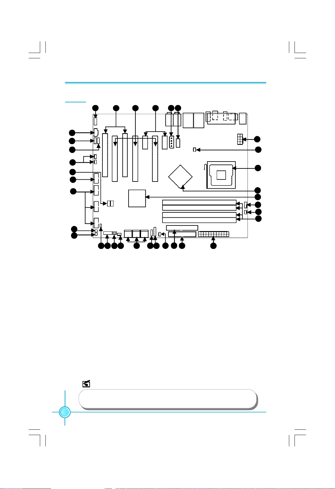
Layout
7
8
9
Chapter 1 Product Introduction
6
5 4
2 1
3
30
29
31
10
11
12
13
14
16 2018 19
15 17
1. COM1 Connector
2. AUX Power Connector:PWR3
3. PCI Express x1 Slot
4. PCI Express x16 Slot
5. PCI Slots
6. Front Audio Connector
7. CD_IN Connector
8. Speaker Connector
9. SPDIF_OUT Connector
10. Debug _LED
11. 1394 Connector
12. Front USB Connectors
13. Power on Button
14. Reset Button
15. Chassis Intruder Connector
16. Front Panel Connector
29
NOTE:
28
27
26
25
31
24
21
31
22
17. Onboard_LED
18. SATA II Connectors
19. Clear CMOS Jumper
20. IrDA Header
21. IDE Connector:PIDE
22. FDD Connector
23. 24-pin ATX Power Connector: PWR1
24. DDR2 DIMM Slots
25. CPU_Fan Connector
26. South Bridge: nVIDIA® MCP55XE Chipset
27. North Bridge: nVIDIA® C55XE Chipset
28. LGA 775 CPU Socket
29. Chipset FAN1/2 Connector
30. 8-pin ATX_12V Power Connector:PWR2
31. System_FAN1/2/3/4 Connector(reserved)
23
The above motherboard layout is provided for reference only,
please refer to the physical motherboard.
4
Page 13
Chapter 1 Product Introduction
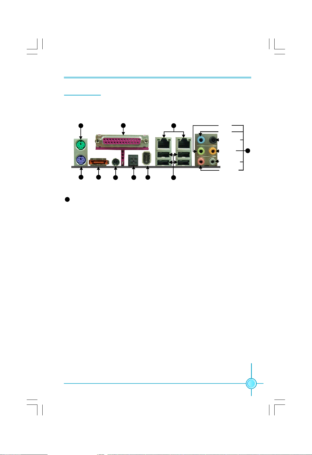
Rear I/O Ports
This motherboard provides the ports as below:
PS/2 Mouse
Port
1
Parallel Port
(Print Port)
10
Lan Port(-K)
9
Line-out
Line-in
Rear Sperker
CEN/LFE
Side Sperker
Microphone
2
PS/2
Keyboard Port
8
Line in, Line out, Microphone, Rear, LEF/CEN, Side Jacks
3
External
SATA Port
4
S/PDIF
Coax Port
5
S/PDIF
Optical Port
6
1394 Single
port
7
USB 2.0 Ports
When using 8-channel sound source, connect the front speaker to the green
audio output; connect the rear sound speaker to the black audio output; con-
nect the center speaker/subwoofer to the orange audio output; connect the side
sound speaker to the grey audio output.
8
5
Page 14

Chapter 1 Product Introduction
Chapter
This chapter introduces the hardware installation process, in-
cluding the installation of the CPU, memory, power supply,
slots, and pin headers, and the mounting of jumpers. Cau-
tion should be exercised during the installation of these
modules. Please refer to the motherboard layout prior to any
installation and read the contents in this chapter carefully.
This chapter includes the following information:
2
2
v CPU
v Memory
v Power supply
v Other Connectors
v Expansion Slots
v Jumpers
6
Page 15
Chapter 2 Installation Instructions
CPU
This motherboard supports Intel® CoreTM 2 Quad,CoreTM 2 Extreme,CoreTM 2 Duo
processors in an LGA775 package with a Front Side Bus (FSB) of 1333/1066/
800MHz.
For the detailed CPU support list on this motherboard, please visit the
website: http://www.foxconnchannel.com
Installation of CPU
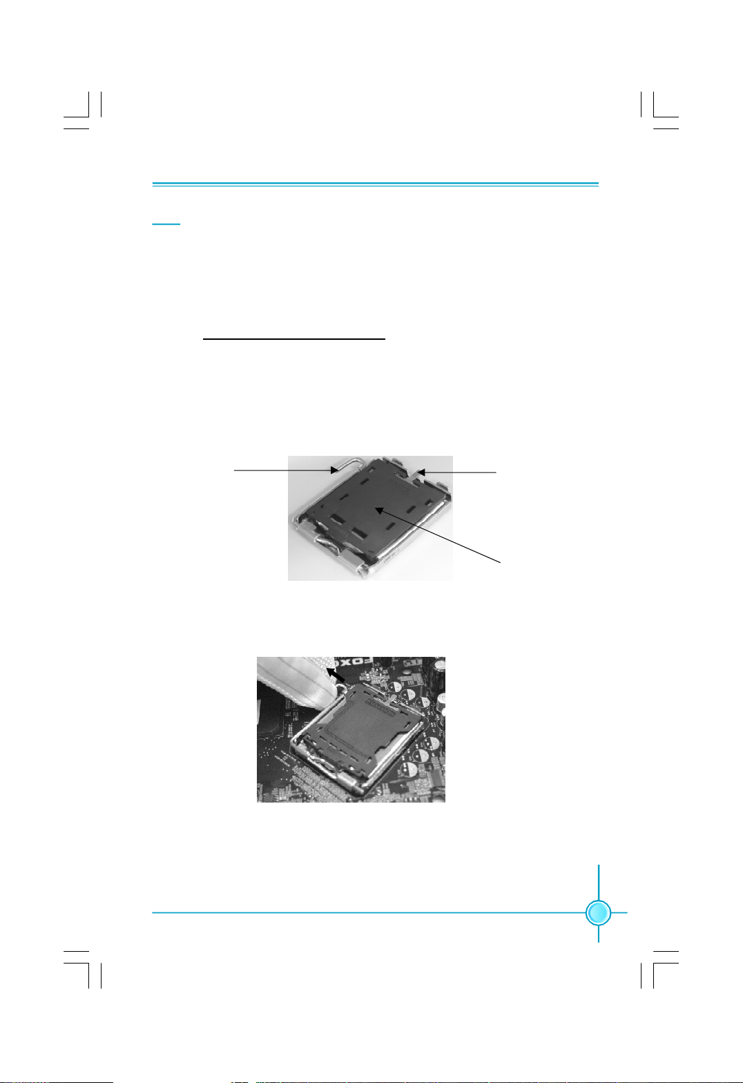
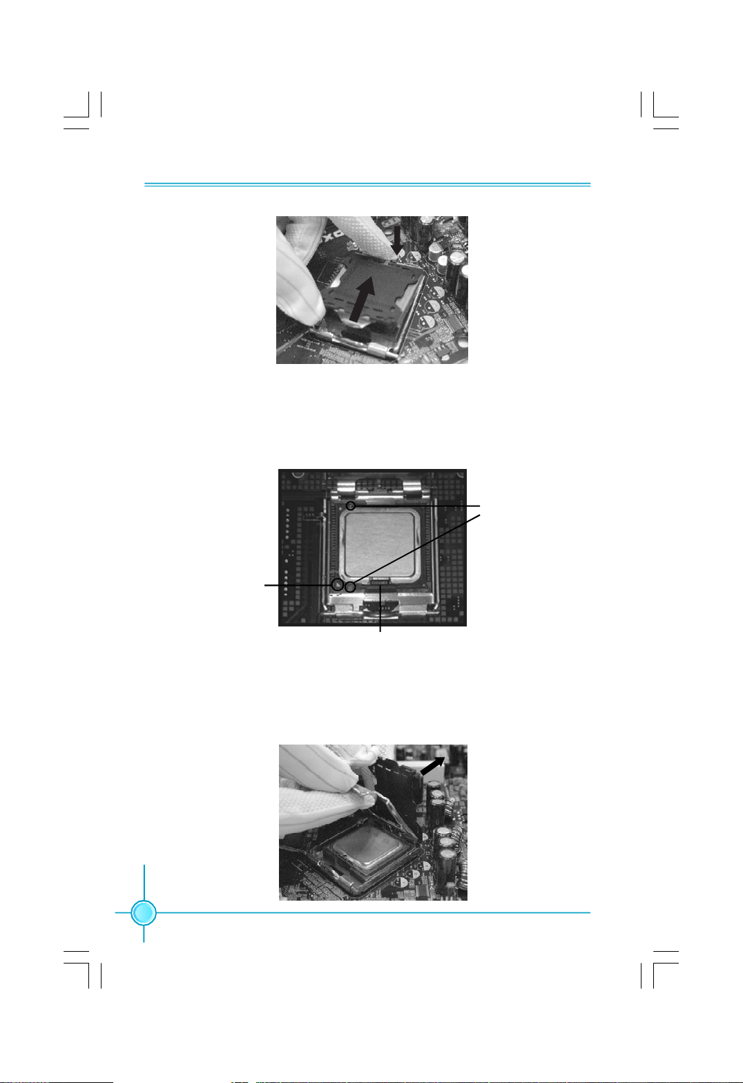
Below is the CPU socket illustration. Follow these procedures to install a CPU.
Load lever
1. Use thumb and forefinger to hold the hook of the load lever and pull the lever
down and away from socket to unlock it. Lift the load lever.
2. Push down the rear tab with your forefinger to bring the front end of the load
plate up slightly. Open the load plate with thumb. Be careful not to touch the
contacts.
Load plate
Protective cover
7
Page 16
Chapter 2 Installation Instructions
3. Hold CPU with thumb and forefinger. Ensure fingers align to socket cutouts.
Match the CPU triangle marker to Pin 1 position as shown below. The alignment
key also provides the orientation directed function. Lower the CPU straight down
without tilting or sliding the CPU in the socket.
Alignment
Key
Pin 1
position
Socket
Cutouts
4. After installing the CPU, remove the protective cover from load plate. The
protective cover is used to protect the contacts of the socket. Do not discard the
protective cover. Always replace the socket cover if the CPU is removed from the
socket.
8
Page 17
Chapter 2 Installation Instructions
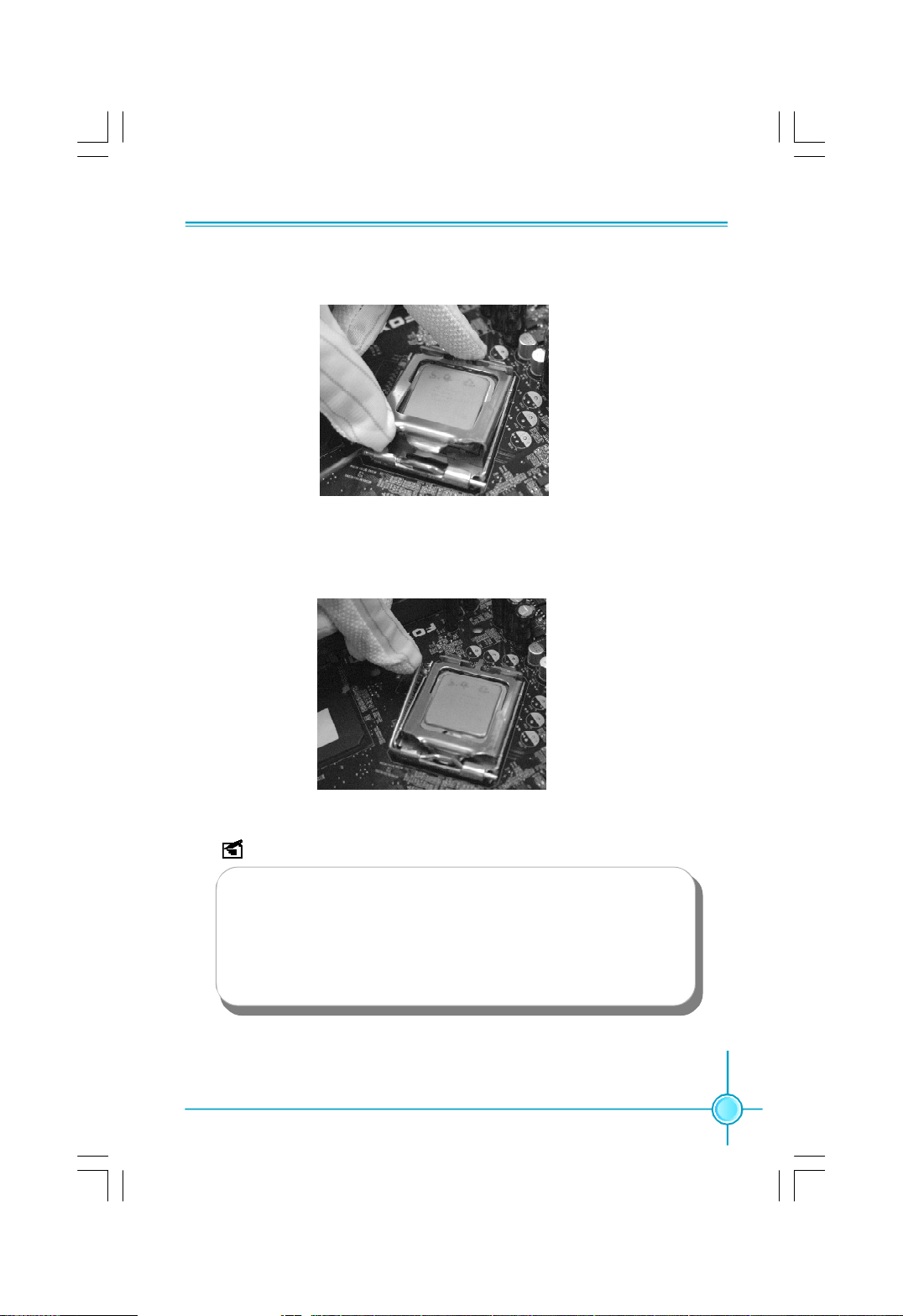
5. Close the load plate, and slightly push down the tongue side.
6. Lower the lever and lock it to the load plate, then the CPU is locked completely.
Note :
Excessive temperatures will severely damage the CPU and
system. Therefore, you should install CPU cooling fan and make
sure that the cooling fan works normally at all times in order to
prevent overheating and damaging to the CPU. Please refer to your
CPU fan user guide to install it properly.
9
Page 18
Chapter 2 Installation Instructions
Memory
This motherboard includes four 240-pin slots with 1.8V for DDR2. You must
install at least one memory bank to ensure normal operation.
For the detailed memory support list on this motherboard, please visit the
website: http://www.foxconnchannel.com
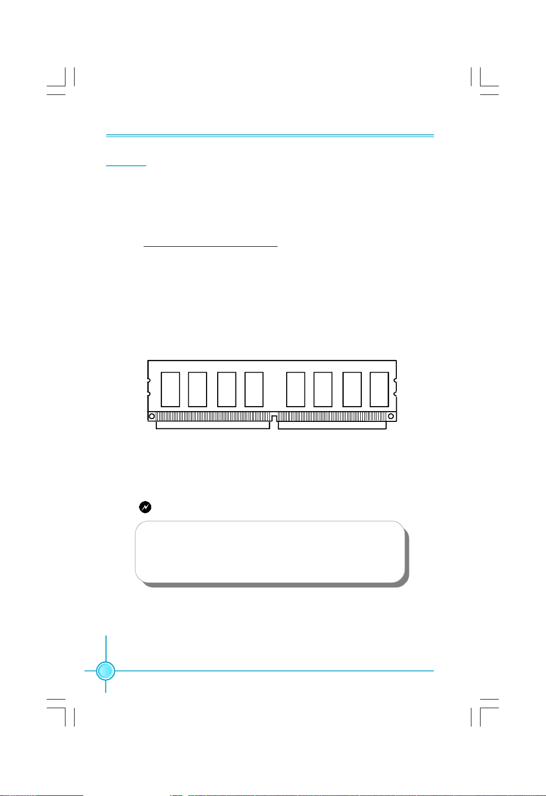
Installation of DDR2 Memory
1.There is only one gap near the center of the DIMM slot, and the memory
module can be fixed in one direction only. Unlock a DIMM slot by pressing the
module clips outward.
2.Align the memory module to the DIMM slot, and insert the module vertically
into the DIMM slot.
128-Pin 112-pin
3.The plastic clips at both sides of the DIMM slot will lock automatically.
Warning:
Be sure to unplug the AC power supply before adding or re-
moving expansion cards or other system peripherals, espe-
cially the memory devices, otherwise your motherboard or the
system memory might be seriously damaged.
10
Page 19
Chapter 2 Installation Instructions
Power Supply
This motherboard uses an ATX power supply. In order to avoid damaging any
devices, make sure that they have been installed properly prior to connecting
the power supply.
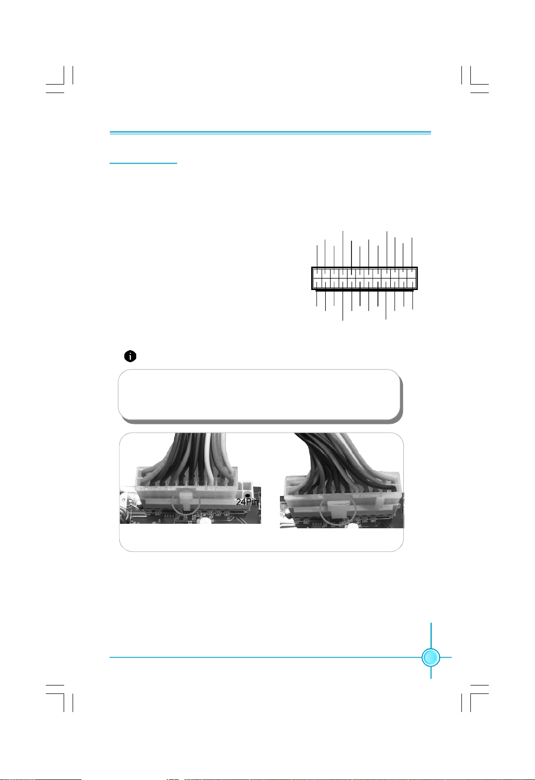
24-pin ATX power connector: PWR1
PWR1 is the ATX power supply connector. Make
sure that the power supply cable and pins are
+3.3V
+5V
+3.3V
GND
GND
1
properly aligned with the connector on the
motherboard. Firmly plug the power supply
cable into the connector and make sure it is
+3.3V
secure.
GND GND
-12V
GND
PSON
24-pin ATX Power Connector
Attention:
We recommend you use 24-pin power supply. If you want to use
20-pin power supply, you need to align the ATX power connector
according to the following picture.
+5V_AUX
+3.3V
+12V
GND
+12V
PWROK
+5V
12
2413
NC
+5V
+5V
+5V
GND
GND
20-Pin Power
24-Pin Power
11
Page 20
Chapter 2 Installation Instructions
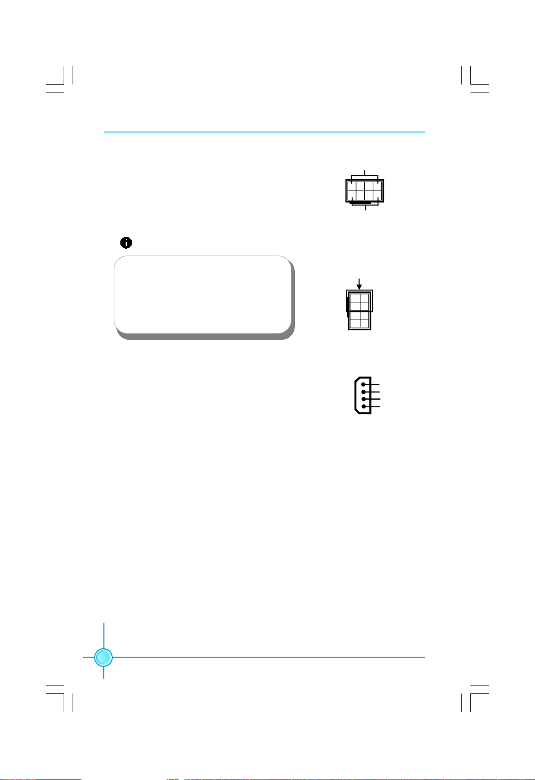
8-pin ATX_12 V Power Connector: PWR2
The 8-pin ATX 12V power supply connects to
PWR2 and provides power to the CPU.
Attention:
We recommend you use 8-pin ATX 12V
power supply. If you want to use 4-pin
power supply, you need to align the ATX
power connector according to the right
picture.
Exclusive Graphics power Connector: PWR3
This connector is a auxiliary power for graphics
card.Exclusive power for graphics card is for
beter graphics performance and for future up-
grade usage.
GND
1
5
8-pin ATX_12 V Power Connector
4
8
12V
Connect a 4-pin power
plug here
5 1
8
Exclusive Graphics power Connector
4
1
+5V
GND
GND
+12V
4
12
Page 21

Chapter 2 Installation Instructions
Other Connectors
This motherboard includes connectors for FDD device, IDE device,Serial ATA
devices, USB devices, IR module, and others.
FDD Connector: FLOPPY
This motherboard includes a standard FDD connector, supporting 360K, 720K,
1.2M, 1.44M, and 2.88M FDDs.
IDE Connectors: PIDE
These connectors support the provided UltraDMA133/100/66 IDE hard disk rib-
bon cable and you can configure as a disk array through RAID controller. Refer
to RAID manual (in CD) for details on how to set up RAID configurations.
Attention:
If you install two IDE device, you must configure the second drive
as a slave device.
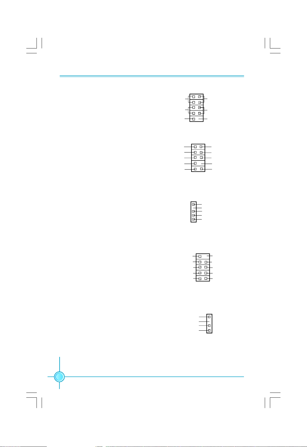
Front Panel Connector: FP1
This motherboard includes one connector for connecting the front panel switch
and LED indicators.
Hard Disk LED Connector (HDD-LED)
The connector connects to the case’s IDE indicator LED indicating the activity
status of hard disks.
Reset Switch (RESET)
Attach the connector to the Reset switch on the front panel of the case; the
system will restart when the switch is pressed.
Power LED Connector (PWRLED)
Attach the connector to the power LED on the front panel of the case. The Power
LED indicates the system’s status. When the system is in S0 status, the LED is
on. When the system is in S1 status, the LED is blink; When the system is in S3,
S4, S5 status, the LED is off.
13
Page 22
Chapter 2 Installation Instructions
Power Switch Connector (PWRSW)
Attach the connector to the power button
of the case. Pushing this switch allows
the system to be turned on and off rather
than using the power supply button.
Audio Connector: F_AUDIO
The audio connector supports HD audio standard. It provides two kinds of audio output choices: the Front Audio, the
Rear Audio. Front Audio supports re-task-
ing function.
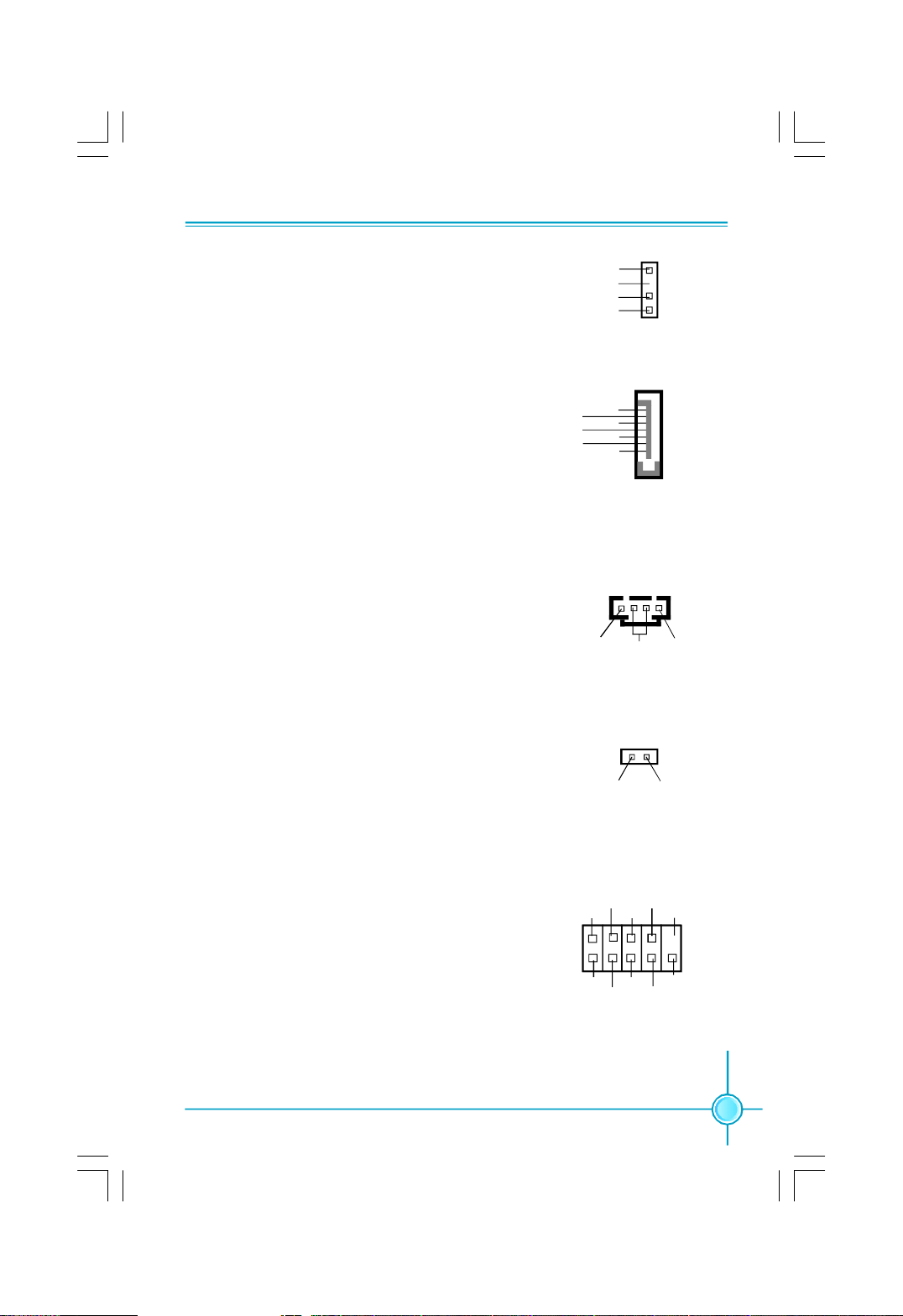
IrDA Connector: IR
This header supports wireless transmit-
ting and receiving device. Before using
this function, configure the settings of
IR Mode from the “Advanced BIOS
Fetures” section of the CMOS Setup.
1394 Connector: F_1394
The 1394 expansion cable can be con-
nected to either the front (provided that
the front panel of your chassis is
equipped with the appropriate
interface) or real panel of the chassis.
HDD-LED
RESET-SW
NC
PORT1_L
PORT1_R
PORT2_R
SENSE_SEND
PORT2_L
1 2
+
-
GND
+12V
TPB -
GND
TPA -
9 10
FPFP1!
1
F_AUDIO
1
IR
F_1394
+
PWR-LED
-
PWR-SW
Empty
AUD_GND
PRESENCE_J
SENSE1_RETURN
Empty
SENSE2_RETURN
+5V
Empty
IRRX
GND
IRTX
910
Empty
+12V
TPB +
GND
TPA +
12
S/PDIF Out Connector: SPDIF_OUT
The SPDIF OUT connector is capable of
providing digital audio to external
speaker or compressed AC3 data to an
external Dolby digital decoder.
14
+5V
Empty
SPDIF_OUT
GND
SPDIF_OUT
1
Page 23
Chapter 2 Installation Instructions
Speaker Connector:SPEAKER
The speaker connector is used to connect
speaker of the chassis.
Serial ATA II Connectors: SATA_1-2, SATA_3-4,
SATA_5-6
The Serial ATA II connector is used to connect the
Serial ATA II device to the motherboard. These
connectors support the thin Serial ATA II cables
for Serial ATA II devices. The current Serial ATA II
interface allows up to 300MB/s data transfer rate.
Audio Connectors: CD_IN
CD_IN is Sony standard CD audio connectors, it
can be connected to a CD-ROM drive through a
CD audio cable.
Chassis Intruder Connector: INTR
The connector connects to the chassis security
switch on the case. The system can detect the
chassis intrusion through the status of this
connector. If the connector has been closed once,
the system will send a message.
SPKJ
Empty
NC
SPKJ
SPEAKER
GND
RX+
RX-
GND
TX-
TX+
GND
SATA_1/2/3/4/5/6
1
CD_L
CD_IN
1
INTRUDERJ GND
GND
INTR
1
1
CD_R
COM Connector: COM1
This motherboard provides an additional serial
COM header for your machine.Connect one side
of a switching cable to the header, then attach
the serial COM device to the other side of the
cable.
2
1
RLSD
DTR
SOUT
CTS
DSR SIN
GND
COM1
RTS
Empty
10
9
RI
15
Page 24
Chapter 2 Installation Instructions
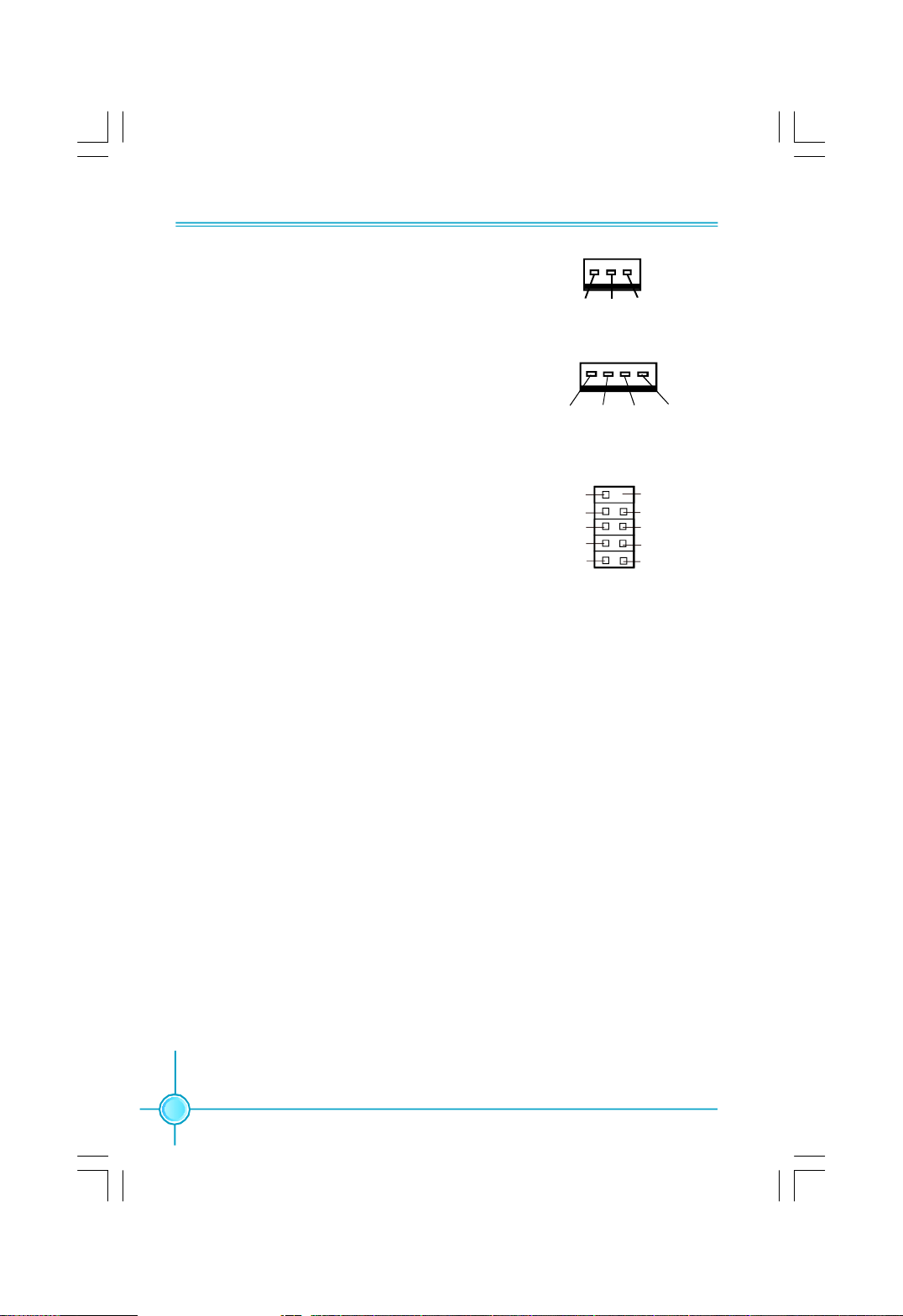
Fan Connectors: CPU_FAN, SYS_FAN1/2/3/
4,FAN1/2
there are seven fan connectors on this
motherboard.The fan speed can be detected
and viewed in “Hardware Health Configure”
section of the CMOS Setup. These fans will be
automatically turned off after the system en-
ters S3, S4 and S5 mode.
USB Connectors: F_USB1/2/3
Besides four USB ports on the rear panel,the
series of motherboards also have three 10-pin
connectors on board which may connect to the
front panel USB cable to provide additional six
USB ports.
1
GND
+12V
SENSE
SYS_FAN1/2/3/4,FAN1/2
1
GND
POWER CONTROL
SENSE
CPU_FAN
NC Empty
1
GND
D+
D-
5V_DUAL
GND
D+
D-
5V_DUAL
F_USB 1/2/3
16
Page 25

Chapter 2 Installation Instructions
Expansion Slots
This motherboard includes two32-bit master PCI slots,two PCI Express x 1 slot
and three PCI Express x 16 slot.
For the detailed PCI Express cards support list on this motherboard, please
visit the website: http://www.foxconnchannel.com
PCI Slots
The expansion cards can be installed in the two PCI slots. PCI slots support
cards such as a LAN card, USB card, SCSI card and other cards that comply
with PCI specifications.
PCI Express x1 Slot
This motherboard has two PCI Express x1 slots that designed to accommodate
less bandwidth-intensive cards, such as a modem or LAN card.The PCI Ex-
press x1 slot offering 250MB/s(500MB/s concurrent) of bandwidth.
PCI Express x16 Slot
This motherboard has three PCI Express x16 slots that reserved for graphics or
video cards. Two of the x16 slots offering 4GB/s (8GB/s concurrent) of bandwidth,
and one offering 2GB/s (4GB/s concurrent) of bandwidth.
Installing an expansion card
1.Before installing the expansion card, read carefully the documentation that
came withit and make the necessary hardware settings for the card.
2.Make sure to unplug the power cord before adding or removing any expan-
sion cards.
3.Remove the bracket opposite the slot that you intend to use.
4.Align the card connector with the slot and press firmly until the card is
completely seated in the slot.
5.Secure the card to the chassis with the screw you removed earlier.
Warning:
If a performance graphics card was installed into x16 PCI Ex-
press slot,24 pin power supply was recommended.
17
Page 26
Chapter 2 Installation Instructions
Jumpers
The users can change the jumper settings on this motherboard if needed. This
section explains how to use the various functions of this motherboard by chang-
ing the jumper settings. Users should read the following content carefully prior to
modifying any jumper settings.
Description of Jumpers
1. For the jumpers on this motherboard, pin 1 can be identified by the bold
silkscreen next to it. However, in this manual, pin 1 is simply labeled as “1”.
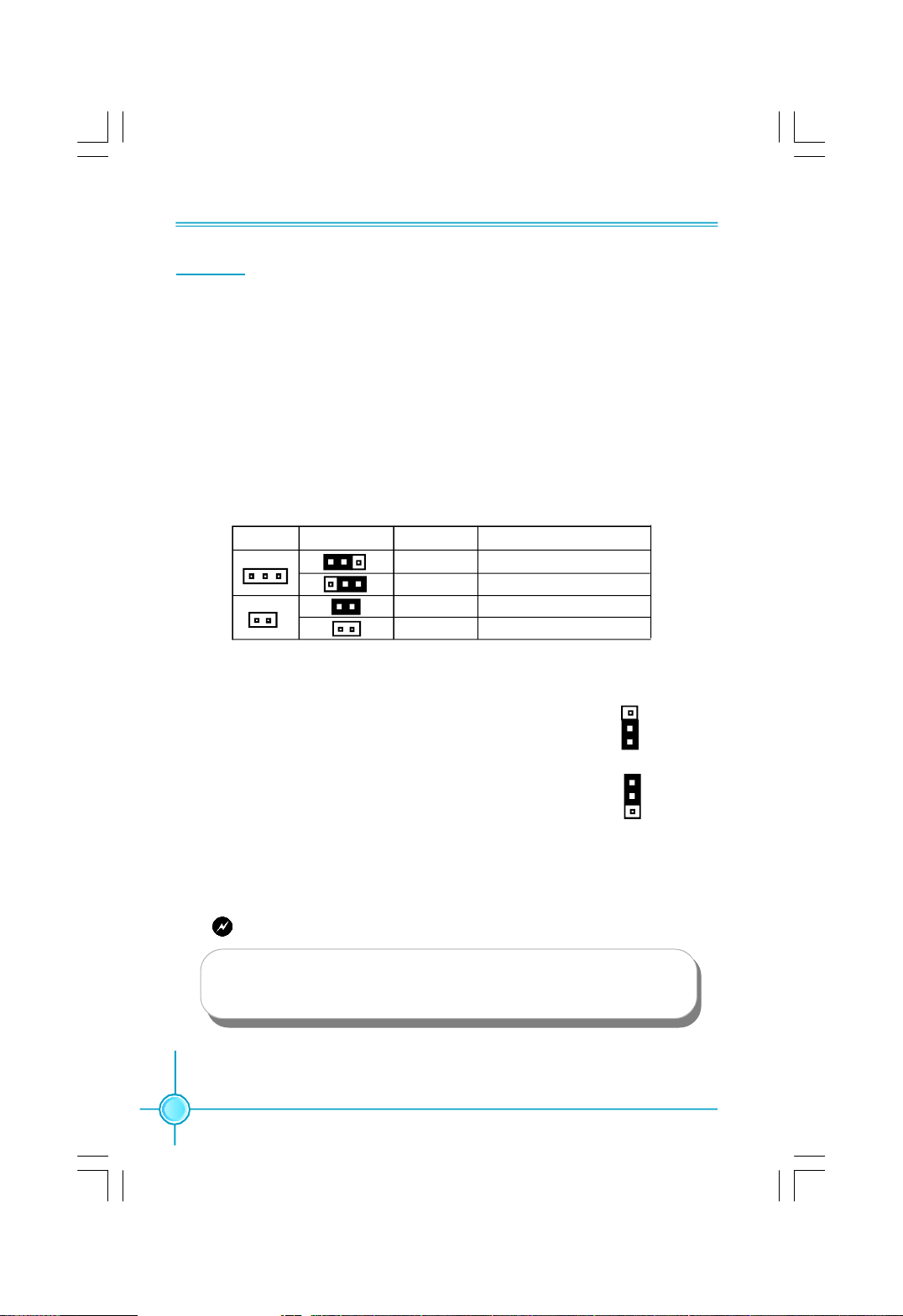
2. The following table provides some explanation of the jumper pin settings.
User should refer to this when adjusting jumper settings.
Jumper Diagram Definition Description
1
1
1
1
1
1
Clear CMOS Jumper: CLR_CMOS
The motherboard uses the CMOS RAM to store all
the set parameters. The CMOS can be cleared by
removing the CMOS jumper.
How to clear CMOS?
1. Turn off the AC power supply and connect pins 1
and 2 together using the jumper cap.
2. Return the jumper setting to normal (pins 2 and
3 together with the jumper cap).
3. Turn the AC power supply back on.
1-2 Set pin 1 and pin 2 closed
2-3 Set pin 2 and pin 3 closed
Closed Set the pin closed
Open Set the pin opened
Normal
(default)
Clear
Clear CMOS Jumper
1
2
3
1
2
3
18
Warning:
1. Disconnect the power cable before adjusting the jumper settings.
2. Do not clear the CMOS while the system is turned on.
Page 27
Chapter 3 BIOS Description
Chapter
This chapter tells how to change system settings through the
BIOS Setup menus. Detailed descriptions of the BIOS param-
eters are also provided.
You have to run the Setup Program when the following cases
occur:
1.An error message appears on the screen during the system
2.You want to change the default CMOS settings.
This chapter includes the following information:
3
3
POST process.
v Enter BIOS Setup
v Main Menu
v Standard BIOS Features
v Fox Central Control Unit
v Boot Configuration Features
v Advanced BIOS Features
v PCI/PNP Resource Management
v Power Management Setup
v Hardware Health Configure
v BIOS Security Features
v Load Optimal Defaults
v Load FailSafe Defaults
v Save Changes and Exit
v Discard Changes and Exit
19
Page 28
Chapter 3 BIOS Description
Enter BIOS Setup
The BIOS is the communication bridge between hardware and software,
correctly setting up the BIOS parameters is critical to maintain optimal system
performance. Power on the computer, when the following message briefly
appears at the bottom of the screen during the POST (Power On Self Test),
press <Del> key to enter the BIOS CMOS Setup Utility.
Press TAB to show POST Screen, DEL to enter SETUP.
Note:
1.The BIOS setup screens shown in this section are provided for
reference only, please refer to the phyical screens.
2.We do not suggest that you change the default parameters in the
BIOS Setup, and we shall not be responsible for any damage that
result from any changes that you make.
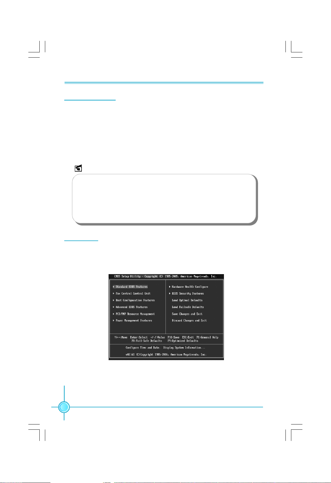
Main Menu
The main menu allows you to select from the list of setup functions and two exit
choices. Use the arrow keys to select among the items and press <Enter> to
accept or go to the sub-menu.
Main Menu
The items in the main menu are explained as below:
Standard BIOS Features
The basic system configuration can be set up through this menu.
20
Page 29

Chapter 3 BIOS Description
Fox Central Control Unit
The special features can be set up through this manu.
Boot Configuration Features
This menu is used for Boot setting.
Advanced BIOS Features
The advanced system features can be set up through this menu.
PCI/PNP Resource Management
The system’s PnP/PCI settings and parameters can be modified through
this menu.
Power Management Features
All the items of Green function features can be set up through this menu.
Hardware Health Configure
This will display the current status of your PC.
BIOS Security Features
This menu is used to set the frequency.
Load Optimal Defaults
The optimal performance settings can be loaded through this menu,
however,the stable default values may be affected.
Load Failsafe Defaults
The Failsafe default BIOS settings can be loaded through this menu.
Save Changes and Exit
Save CMOS value settings to CMOS and exit setup.
Discard Changes and Exit
Abandon all CMOS value changes and exit setup.
21
Page 30

Chapter 3 BIOS Description
Standard BIOS Features
This sub-menu is used to set up the standard BIOS features, such as the date,
time,floppy driver and so on. Use the arrow keys select the item to set up, and
then use the <+> or <-> keys to choose the setting values.
Standard BIOS Features Menu
Processor
This option shows the information of the system processor.
system Memory
This option shows the information of the system memory,detemined by POST
(Power On Self Test) of the BIOS.
System Time/Date
This option allows you to set up the desired time and date(usually as the
current time and date) with <hour><minute><second><day><month><date>
<year> format.
Day—weekday from Sun. to Sat., defined by BIOS (read-only).
Month—month from 1 to 12
Date—date from 1st to 31
st
Year—year, set up by users.
Use [ENTER],[TAB]or [SHIFT-TAB] to select a field.Use [+] or [-] to configure
system time and date.
Floppy A
This option allows you to select the kind of FDD to be installed, including
[360K, 5.25 in], [1.2M, 5.25in], [720K, 3.5 in], [1.44M, 3.5 in],[2.88 M, 3.5 in].
22
Page 31

Chapter 3 BIOS Description
Fox Central Control Unit
Fox central control Unit Menu
vSmart power LED
Enable this function,the smart LED can show the system status of POST
process.
vFox Intelligent Stepping
User can select different overcloking option by this item.
vOverclock Options/Voltage Options/CPU Configuration/Hyper Transport Set-
ting/nVidia LinkBoost Technology/Spread Spectrum Control
Press [Enter] to enter the options setup.
vSLI-Ready Memory
This option is used for the SLI-Ready memory technology.
Overclock Options Menu
23
Page 32

Chapter 3 BIOS Description
vSystem Clock Mode
This item is used to set the system clock mode. select [Auto] to set FSB and
Memor clock automatically;select [Linked] allows memory and FSB to overclock
proportionally;select [Manual] to enter FSB and memory clock manually.
vMemory Timings
This item is used to set the memory timings. Select [Auto] to set memory
timings automatically;select [Manual] to set memory timings manually.
Voltage Options Menu
vCPU Voltage Margining Offset
This option is used to set the CPU voltage margining offset. Voltage margin-
ing add.every setp is 0.0125V.
vMemory Voltage Control
This option is used to set the memory voltage.
vnForce SPP/nForce MCP Voltage
This options are used to set the nForce SPP/nForce MCP voltage.
vMemory Terminal Voltage
This option is used to set the memory terminal voltage.
vVLDT Voltage Control
This option is used to set the VLDT voltage.
24
Page 33

Chapter 3 BIOS Description
CPU Configuration menu
vC1E Support
This option is used to set the C1E support.It should be enabled in order to
enable or disable the”Enhanced Halt State”.
vHardware Prefetcher
This option is used to enable or disable the hardware prefetcher function.
vAdjacent Cache Line prefetch
This option is used to enable or disable the Adjacent Cache Line prefetch
function.
vMax CPUID Value Limit
This option is used to enable or disable the Max CPUID value limit function.
Enabled this function for Prescott CPU and OS that can not use this function
(e.g.,NT4.0).Disabled for WindowsXP.
vVaoterpool Technology
This option is used for Intel Vaoterpool Technology.
v Execute Disable Bit
This option is used to enable or disable the Execute Disable Bit feature.
Execute Disable Bit capability is a robust hardware feature, detectable using
the CPUID instruction, that protects against malicious software executing
code on IA-32 systems.
vCore Multi-Processing
When disabled this option only Core 0 ,logical processor 0 remains active.
25
Page 34

Chapter 3 BIOS Description
vIntel(R) SpeedStep(tm) tech.
This option is used for the Intel speed step technology.
[Maximum]:CPU speed is set to maximum.
[Minimum]:CPU speed is set to minimum.
[Automatic]:CPU speed controlled by operating system.
[Disabled]:default CPU speed.
Hyper Transport Setting manu
vMCP to SPP Frequency
This item is used to set C55(NB) to NVIDIA(SB) frequency.
vMCP to SPP LinkWidth
This item is used to set C55(NB) to NVIDIA(SB) link width.
vSPP to MCP Frequency
This item is used to set MCP55(SB) to NVIDIA(NB) frequency.
vSPP to MCP LinkWidth
This item is used to set MCP55(SB) to NVIDIA(NB) link width.
26
Page 35

Chapter 3 BIOS Description
nVidia LinkBoost Technology menu
vNB<->SB LinkBoost Support
This option is used to set the LinkBoost support between north bridge and
south bridge.
vPCIE LinkBoost Support
This option is used to set the PCIE LinkBoost support.
vPCIE Slot 1/2/3 Frequency (MHz)
This options are used to adjust the frequency of the PCIE slots.The range is
100~200MHz and the step is 1MHz.
Spread Spectrum Control Menu
vCPU / C55 PCIE / CPU/LDT / MCP55 PCIE / SATA Spread Spectrum
This items are used to set the CPU /C55 PCIE/CPU/LDT/MCP55 PCIE/SATA
spread spectrum functions.
NOTE:The Spread Spectrum function can influence the EMI degree.
27
Page 36

Chapter 3 BIOS Description
Boot Configuration Features
Boot Configuration Features Menu
vQuick Boot
While Enabled,this option allows BIOS to skip certain tests while booting,this
will decrease the time needed to boot the system.
vQuiet Boot
This item is used to enable or disable the quiet boot.
[Disabled]:Displays nomal POST messages.
[Enabled]:Displays OEM Logo instead of POST messages.
vAddOn ROM Display Mode
This item is used to set the display mode for option ROM.When Quiet Boot is
enabled, this option controls whether output from the option ROM is displayed.
The available setting values are:Force BIOS;Keep Current.
vBootup Num-Lock
This item defines if the keyboard Num Lock key is active when your system is
started. The available setting values are On and Off.
vWait For ‘F1’ If Error
This item is used to set whether wait for ‘F1’ key to be pressed if error occurs.
Enabling this option causes the system to pause the POST if it encounters an
error, and wait for user to press the F1 key before resuming.
vHit ‘DEL’ Message Display
This item is used to set whether shows the information about press DEL to
run BIOS setup in POST.
28
Page 37

Chapter 3 BIOS Description
vBoot Device Priority
This option is used to select the priority for devices. After pressing
<Enter>, you can select the devices using the <PageUp>/<PageDn> or Up/
Down arrow keys, and change the devices priority using <+> or <->; you can
exit this menu by pressing <Esc>.
vHard Disk Drives
This option is used to specify the Boot Device priority sequence from
available removable hard disk drives.
vRemovable Drives
This option is used to specify the Boot Device priority sequence from
available removable drives.
vCD/DVD Drives
This option is used to specify the Boot Device priority sequence from
available removable CD/DVD drives.
Advanced BIOS Features
Advanced BIOS Features Menu
Use the arrow keys to select your options;Press [Enter] to enter the setup
sub-menu.The options are discussed below:
29
Page 38

Chapter 3 BIOS Description
IDE Configuration Menu
vOnboard IDE Controler
This option is used to enable or disable the integrated IDE controler.
vSerial-ATA Devices
This option is used to set the SATA devices.
The available values are: [Disabled];[Device 0];[Device 0/1];[Device 0/1/2].
vnVIDIA RAID Setup
Press [Enter] to enter setup,you can choose enabled or disabled RAID mode
for each ATA channels.
vPrimary IDE Master/Slave, S-ATA 0/1/2 Primary/Secondary Channel
While entering setup,BIOS auto detects the presence of IDE devices,this displys
the status of auto detection of IDE devices.
vIDE Detect Time Out (Sec)
This option is used to select the time out value for detecting ATA/ATA API devices.
If overed this setting time,the system will skip over the detect.
30
Page 39

Chapter 3 BIOS Description
SuperIO Configuration Menu
vOnBoard Floppy Controller
This option allows BIOS to enable or disable floppy Controller.
vSerial Port1/2 Address
This option is used to assign the I/O address and interrupt request (IRQ) for
the onboard serial port .
Note: Do not try to set the same values for serial ports 1 and 2.
vIrDA Mode
This option allows BIOS to select mode for serial port 2.
vIR Duplex Mode
This option allows BIOS to select full or half duplex for serial port 2.
vIRTX Pin Select
This option allows BIOS to select transmit pin in normal condition or
inverse the IRTX.
vIRRX Pin Select
This option allows BIOS to select receiver pin in normal condition or
inverse the IRRX.
vIR Tx to Rx Delay Select
This option allows BIOS to select IR from Tx to Rx 4characters time delay for
serial port 2.
vIR Rx to Tx Delay Select
This option allows BIOS to select IR from Rx to Tx 4 characters time delay for
serial port 2.
vParallel Port Address
This option is used to assign the base address for the onboard parallel port.
31
Page 40

Chapter 3 BIOS Description
vParallel Port Mode
This option is used to set the parallel port mode.
vParallel Port IRQ
This option is used to determine onboard parallel port IRQ.
OnBoardDevice Configuration Menu
vUSB 1.1/2.0 Controller
This option is used to set whether the USB 1.1/2.0 Controller is enabled.
vLegacy USB Support
This option is used to set the support for USB devices on legacy OS.Auto
option disables legacy support if no USB devices are connected.
vUSB Devices Enabled:
This option display the enabled USB devices connected to your PC.
vPrimary Graphics Adapter
This option is used to set the primary graphics adapter.The available setting
values are PCI Express and PCI.
vAzalia Audio
This option is used to set the onboard Azalia audio.
vMAC0 LAN0/MAC1 LAN1
This option is used to set whether the onboard LAN controller is enabled.
vOnboard 1394/ e-SATA Device
This option is used to enable or disable the onboard 1394/e-SATA.
ve-SATA Mode Select
This option is used to set the e-SATA mode select.
32
Page 41

Chapter 3 BIOS Description
PCI/PNP Resource Management
PCI/PNP Resource Management Menu
vIRQ & DMA Settings
Press [Enter] to enter the IRQ and DMA setup.
vClear NVRAM
This item is used to set whether clearing the NVRAM during system boot.
vPlug & Play O/S
This item is used to set the plug and play function for your OS.
[No]:Lets the BIOS configure all the devices in the system.
[Yes]:Let the operating system configure plug and play devices not required
for boot if your system has a plug and play operating system.
vPCI Latency Timer
This option is used to set the PCI latency timer. The value is in units of PCI
clock for PCI device latency timer register.
vAllocate IRQ to PCI VGA
This item is used to set if allocate IRQ to PCI VGA.
[Yes]:Assigns IRQ to PCI VGA card if card requests IRQ.
[No]:Does not assign IRQ to PCI VGA card even if card requests an IRQ.
vPalette Snooping
This item is used to set whether the palette snooping is enabled.
vPCI IDE BusMaster
This item is used to set whether the PCI IDE bus master is enabled.If enabled,
the BIOS can use PCI bus mastering for reading/writing to IDE drives.
33
Page 42

Chapter 3 BIOS Description
vOffBoard PCI/ISA IDE Card
This item is used to set the offboard PCI/ISA IDE card.Some PCI IDE cards
may require this to be set to the PCI slot number that is holding the card.
IRQ & DMA Settings Menu
vIRQ 3/4/5/7/9/10/11/14/15,DMA Channel 0/1/3/5/6/7
This options are for IRQ/DMA to deceide whether or not to let PnP automati-
cally configrate.Specified IRQ/DMA is available to be used by PCI/PnP devices.
vReserved Memory Size
This item is used to set the size of memory block to reserve for legacy ISA
devices.
Power Management Features Setup
Power Management Features Menu
34
Page 43

Chapter 3 BIOS Description
vSuspend mode
This option is used to select the ACPI state used for system suspend.
vRepost Video on S3 Resume
This option is used to set if opened the repost video on S3 resume function,
it allows the system to initialize the PCI BIOS POST from S3(Suspend to RAM)
sleep state.
vACPI Version Features
This option is used to select the ACPI version.
vACPI APIC support
This option is used to set if add the ACPI APIC table pointer to RSDT pointer
list.
vMCP55 ACPI HPET TABLE
This option is used to enable or disable the MCP55 ACPI HPET TABLE.
vPower Button Mode
This option is used to set the power button mode.You can select On/Off or
suspend mode for the event that power button is pressed.
vVideo Power Down Mode
This option is used to enable or disable the video power down in suspend
mode.
vHard Disk Power Down Mode
This option is used to enable or disable the hard disk power down in suspend
mode.
vHard Disk Time Out (Minute)
This option is used to set the hard disk time out in specified minutes.
vRestore on AC Power Loss
This option is used to set what action the PC will take with the power
supply when it restores after the AC power loss.
The available setting values are:[power off],[power on],[last state].
vResume On PME# / PCIE Wake# / LAN(MAC) / Ring / PS/2 Keyboard /
PS/2 Mouse / RTC Alarm
This options are used to enable or disable PME/PCIE Wake/LAN(MAC) /Ring
/PS/2 Keyboard / PS/2 Mouse /RTC event to generate a wake event.
35
Page 44

Chapter 3 BIOS Description
Hardware Health Configure
Hardware Health Configure Menu
vFan 1 Mode Setting
This option is used to set the fan 1 configuration mode.
vTemperature 1 Limit of Hig/Sec/Thi/Low
This options are used to set the fan temperature limit.
vFan 1 Highest/Second/Third/Fourth/Lowest Setting
This options are used to set the fan speed.
vCase Open Warning
This option is used to enable or disable Intruder Detection function.
vWarning Temperature
This option is used to set the warning temperature for the system.When the
temperature of CPU is higher than setting value,the motherboard will send off
warning information.
vCPU Temperature /System Temperature/CPU Fan Speed/ Fan Speed/
System Fan Speed/Vcore/+1.8V SUS/+1.2V CORE/+5V/VCC/VSB/VBAT
These items display the current CPU/chipset/system temperature,fan
speed and voltages that automatically detected by the system.
36
Page 45

Chapter 3 BIOS Description
BIOS Security Features
BIOS Security Features Menu
vChange Supervisor/User Password
This option is used to install or change supervisor/user password.
vBoot Sector Virus Protection
This option is used to protect your PC from being affected by viruses.The
available setting values are Disabled and Enabled.
vBIOS Write Protect
This option is used to enable or disable the BIOS write protect.
vBIOS BootBLock Write Protect
This option is used to enable or disable the BIOS BootBLock write protect.
37
Page 46

Chapter 3 BIOS Description
Load Optimized Defaults
Select this option and press Enter, it will pop out a dialogue box to let you load
the optimized defaults set by BIOS. Select <Y> and then press <Enter> to load
the optimized defaults. Select <N> and press <Enter>, it will not load. The defaults set by BIOS have set the optimized performance parameters of system to
improve the performances of system components. But if the optimized performance parameters to be set cannot be supported by your hardware devices, it
will cause system to make mistakes or not stable.
Load Failsafe Defaults
Select this option to press <Enter>, it will pop out a dialogue box to allow you to
load default set by BIOS. Select <Y> and then press Enter to load default. Select
<N> and press <Enter>, it will not load. The defaults set by BIOS have set the
basic functions of system in order to ensure the stability of system. But if your
computer fails to properly run, you may load the default to make the system
recover normal, then carry out failure testing in next step.
Save Changes and Exit
When you select this option and press <Enter>, the following message will
appear in the center of the screen:
SAVE to CMOS and EXIT (Y/N)?Y
Press <Y> to save your changes in CMOS and exit the program; press <N> or
<ESC> to return to the main menu.
Discard Changes and Exit
If you select this option and press <Enter>, the following message will appear
in the center of the screen:
Quit Without Saving (Y/N)?Y
Press<Y> to exit CMOS without saving your modifications; press<N>or<ESC>
to return to the main menu.
38
Page 47

Chapter 4 Driver CD Introduction
Chapter
The utility CD that came with the motherboard contains useful
software and several utility drivers that enhance the motherboard
features.
This chapter includes the following information:
4
4
v Utility CD content
v Installing drivers and software
39
Page 48

Chapter 4 Driver CD Introduction
Utility CD content
This motherboard comes with one Utility CD. To begin using the CD, simply
insert the CD into your CD-ROM drive. The CD will automatically displays the
main menu screen.
1. Install Driver
Using this options to install all the drivers for your motherboard. You should
install the drivers in order,and you need to restart your computer after all the
drivers installed.
A.NVIDIA nForce drivers
C.Microsoft DirectX 9.0C
2. Software
Using this options to install additional software programs.
B. ESATA drivers
D. Realtek Audio Drivers
A. FOX ONE
C. nTune
E. Norton Internet Security
3. Creat RAID Driver Floppy
Click here to creat RAID or e-SATA driver floppy.
A.Create(32bit)nVidia SATA
RAID Floppy
C.Create(32bit)JMicron
e-SATA Floppy ( AHCI Mode)
4. User Manual
Click here to browse the detailed manual content.
40
B. Fox LiveUpdate
D. Adobe Reader
B. Create(64bit)nVidia SATA
RAID Floppy
D. Create(64bit)JMicron
e-SATA Floppy ( AHCI Mode)
Page 49

Chapter 4 Driver CD Introduction
5. Browse CD
Click here to browse CD content.
6. Foxconn Website
Click here to visit our homepage.
Installing drivers and software
1. Install Driver
Click the driver that you want to install and begin the steps in order.
2. Install Software
You can select the software that you want to install and begin the setup steps.
41
Page 50

Chapter 4 Driver CD Introduction
3. Creat RAID Driver Floppy
“Create (32/64bit) nVidia SATA RAID Floppy” is used for creating RAID driver
floppy.
“Create(32/64bit)JMicron e-SATA Floppy ( AHCI Mode)” is used for creating e-
SATA driver floppy.
42
Page 51

Chapter 4 Driver CD Introduction
Chapter
This chapter will introduce how to use attached software.
This chapter provides the following information:
5
5
v FOX ONE
v FOX LiveUpdate
43
Page 52

Chapter 5 Directions for Bundled Software
FOX ONE
FOX ONE is a powerful utility for easily modifying system settings. It also allows
users to monitor various temperature values, voltage values, frequency and fan
speed at any time.
With FOX ONE, you can
-Modify system performance settings, such as bus speeds, CPU voltages,
fan speed, and other system performance options that are supported by the
BIOS
-Monitor hardware temperature, voltage, frequency and fan speed
Supported Operating Systems:
-Windows 2000
-Windows XP (32-bit and 64-bit)
-Windows 2003 (32-bit and 64-bit)
Using FOX ONE:
1. Main Page
44
Show CPU
Information
Toolbar
Monitor Frequency/Voltage/Fan
speed/Temperature value
Alert Lamp
Switch Button
Skin Button
Exit
Minimum
Configuration
Homepage
Page 53

Chapter 5 Directions for Bundled Software
Toolbar
Use the toolbar to navigate to other pages.
Alert Lamp
When the system is in healthy status, the alert lamp color is green. When the
system is in abnormal status, the alert lamp color is red.
Switch Button
Click this button, it will shorten to below figure. It helps you to minitor your system
healthy status at any time.
Click here to return to
previous status
Skin Button
Click this button, it will show the figure below.You can select your favourite skin.
Apply the changes
Cancel the changes
Exit
Click this button to exit the program.
Minimum
Click this button to minimize the window.
Click the new skin
picture to select the
new skin
45
Page 54

Chapter 5 Directions for Bundled Software
Configuration
Click this button to configurate the parameters for the program. It determines
which items will be shown in shorten mode.
Homepage
Click this button to visit Foxconn motherboard website.
2. CPU Page - CPU Control
This page lets you select and run the FOX ONE developed benchmarks to
determine the current performance level of the system. You can also adjust by
manual. Only this page is set to Manual Adjustment, the Freq., Vlotage, and Fan
pages can be adjusted by manual.
Go to CPU page
Close this page
46
Reset the
changes
Select the different
benchmarks
Ajust by manual
Apply the
changes
Page 55

Chapter 5 Directions for Bundled Software
3. Freq. Page - Frequency Control
This page lets you set memory and PCI Express frequency by manual.
Go to Freq. page
Close this page
Select the option
you want to set
Adjust by manual
Reset the changes
Apply the changes
4.1 Limit Setting - CPU Temp.
This page lets you to set CPU high limit temperature and enable the alert
function.
Show current CPU
Go to Adjust page
temperature value
Enable alert function
when the CPU
temperature is higher
than high limit value
Show current high
limit value of CPU
temperature
Set high limit by
dragging the lever
47
Page 56

Chapter 5 Directions for Bundled Software
4.2 Limit Setting - Sys Temp.
This page lets you to set system high limit temperature and enable the alert
function.
Show current system
temperature value
Enable alert function
when the system
temperature is higher
than high limit value
Show current high
limit value of system
temperature
Set high limit by
dragging the lever
4.3 Limit Setting - CPU Fan
This page lets you to set CPU fan low limit rpm and enable the alert function.
48
Show current CPU
fan rpm value
Enable alert function
when the CPU fan rev
is lower than low limit
rpm value
Show current low limit
rpm value of CPU fan
Set low limit rpm by
dragging the lever
Page 57

Chapter 5 Directions for Bundled Software
4.4 Limit Setting - Sys Fan
This page lets you to set system low limit rpm and enable the alert function.
Show current system
fan rpm value
Enable alert function
when the system fan
is lower than low limit
rpm value
Show current low limit
rpm value of system
fan
Set low limit rpm by
dragging the lever
4.5 Limit Setting - FAN1 Fan
This page lets you to set FAN1 fan low limit rpm and enable the alert function.
Show current FAN1
fan rpm value
Enable alert function
when the FAN1 fan is
lower than low limit
rpm value
Show current low limit
rpm value of FAN1 fan
Set low limit rpm by
dragging the lever
49
Page 58

Chapter 5 Directions for Bundled Software
5. Voltage Page - Voltage Control
This page lets you set CPU voltage, memory voltage and North Bridge voltage
by manual.
Go to Voltage page
Select the option
you want to set
Adjust by manual
Reset the changes
Apply the changes
6. Fan Page - Fan Control
This page lets you enable smart Fan function or set fan speed by manual.
Go to Fan page
Enable or disable
smart fan function
Set fan speed by
dragging the lever
Reset the changes
50
Apply the changes
Page 59

Chapter 5 Directions for Bundled Software
FOX LiveUpdate
FOX LiveUpdate is a useful utility for backuping and updating the system BIOS,
drivers and utilities by local or online.
Supported Operating Systems:
-Windows 2000
-Windows XP (32-bit and 64-bit)
-Windows 2003 (32-bit and 64-bit)
Using FOX LiveUpdate:
1.1 Local Update - BIOS Info.
This page lets you know your system BIOS information.
Toolbar
Link to website
Minimum
Exit
Show current
BIOS information
51
Page 60

Chapter 5 Directions for Bundled Software
1.2 Local Update - Backup
This page lets you backup your system BIOS. Click “Backup”, then give a name.
Click “Save” to finish the backup operation.
Key in a BIOS name
Click here
1.3 Local Update - Update
This page lets you update your system BIOS from Internet. After click “Update”,
there will show warning message, please read it carefully. If you still want to
continue, click “Yes”. Then load a local BIOS file and follow the wizard to finish the
operation.
52
Note:
FOX LiveUpdate will auto backup BIOS before update because we
have enabled this function in Configure option.
Page 61

Chapter 5 Directions for Bundled Software
2.1 Online Update - Update BIOS
This page lets you update your system BIOS from Internet. Click “start”, it will
search the new BIOS from Internet. Then follow the wizard to finish the update
operation.
Click here
Current information
Search new BIOS
from Internet
Select BIOS to update
Browse detail
information
Update BIOS
Close the window
53
Page 62

Chapter 5 Directions for Bundled Software
2.2 Online Update - Update Driver
This page lets you update your system drivers from Internet. Click “start”, it will
search the new drivers from Internet. Then follow the wizard to finish the update
operation.
Click here
Current information
Search new drivers
from Internet
Select the drivers to update
54
Browse detail
information
Install the selected
drivers
Close the window
Page 63

Chapter 5 Directions for Bundled Software
2.3 Online Update - Update Utility
This page lets you update utilities from Internet. Click “start”, it will search the new
utilities from Internet. Then follow the wizard to finish the update operation.
Click here
Current information
Search new utilities
from Internet
2.4 Online Update - Update All
This page lets you update your system drivers from Internet. Click “start”, it will
search all new BIOS/drivers/utilities from Internet. Then follow the wizard to finish
the update operation.
Click here
Current information
Search all new
BIOS/drivers/utilities
from Internet
55
Page 64

Chapter 5 Directions for Bundled Software
3.1 Configure - option
This page lets you set auto search options. After your setting, the utility will start
searching and related information will show on the task bar.
Click here
Set auto
search options
Select search
which kind of
versions
Apply the changes Reset to default value
Note
56
When enable auto search function, FOX LiveUpdate will appear search-
ing result on task-bar. Double click the icon, you can see the detail
information.
Double click here
Page 65

Chapter 5 Directions for Bundled Software
3.2 Configure - System
This page lets you set the backup BIOS location and change different skin of
the utility.
Click here
Set the location of
download files or
auto backup BIOS
Select different skin
of the software
Reset to default value
Determine if the FOX liveUpdate can
auto run when the system starts up
Apply the changes
3.3 Configure - Advance
This page lets you select to flash BIOS / Boot Block and clear CMOS .
Click here
Select which BIOS ROM
to flash(Only available to
MotherBoard with backup
BIOS ROM )
Select to flash Boot Block
Select to clear CMOS
Apply the changes
Attention
we recommend that you’d better keep the default setting un-
changed to avoid damagement.
Reset to default value
57
Page 66

Chapter 5 Directions for Bundled Software
4. About & Help
This page shows some information about FOX LiveUpdate.
Click here
Show information
about FOX LiveUpdate
58
Page 67

Chapter 6 nVIDIA RAID Configurations
Chapter
6
6
This chapter will introduce nVIDIA® RAID Configurations .
This chapter provides the following information:
v Introduction
v BIOS Setup
v RAID BIOS Setup
v NVIDIA RAID Utility Installation
v Initializing and Using the Disk Array
59
Page 68

Chapter 6 nVIDIA RAID Configurations
Introduction
RAID Arrays
This section describes the following types of RAID arrays that NVIDIA RAID
supports:
vRAID 0
RAID 0 defines a disk striping scheme that improves the disk read and write
times for many applications.
vRAID 1
RAID 1 defines techniques for mirroring data.
vRAID 0+1
RAID 0+1 combines the techniques used in RAID 0 and RAID 1 arrays.
vRAID 5
RAID 5 provides fault tolerance and better utilization of disk capacity.
vSpanning (JBOD)
JBOD provides a method for combining drives of different sizes into one large
disk.
Summary of RAID Configurations
Array
RAID 0
RAID 1
RAID
0+1
RAID 5
JBOD
60
Advantages
High data throughput.
100% data redund-
ancy.
Optimized for both
100% data redun-
dancy and per-
formance. Allows
spare disks.
Fault tolerance and
better utilization of disk
space.
ombines and uses the
capacity of odd size
drives.
Drawbacks
No fault tolerance.
Requires two drives
for the storage space
of one drive.
Requires two drives
for the storage space
of one drive - the same
as RAID level 1.
Decreased write per-
formance due to parity
calculations.
Decreases perfor-
mance because of the
difficulty in using drives
concurrently or to op-
timize drives for differ-
ent uses.
# Hard Disks
multiple
2
4+
3+
multiple
Fault Tolerance
None
Yes
Yes
Yes
No
Page 69

Chapter 6 nVIDIA RAID Configurations
Additional RAID Features
NVIDIA RAID offers the following additional features:
v Free Disk and Dedicated Spare Disk
A Free Disk or Dedicated Disk can be automatically used in case one drive of a
fault-tolerant array fails. NVIDIA RAID defines a fault-tolerant array as either
RAID 1, RAID 0+1, or RAID 5. A free disk can be used by any available fault-
tolerant array, while a dedicated disk can be used only by the array to which it is
assigned.
vBootable RAID
This allows you to install the operating system onto the RAID volume.
v Morphing
Morphing is the ability to convert from one RAID mode to another RAID mode.
This allows the user to upgrade their current disk or array for better performance,
higher security, and increased capacity. More importantly, this is accomplished
withouthaving to go through multiple steps. The morphing feature gives the user
an upgradeable option to manage storage easily.
vHot Plug Array
A nice flexibility feature is the ability to move MediaShield RAID arrays from one
nForce system to another. Since most nForce systems support SATA hot plug
capability, you can add/remove a RAID array even while the system is running.
This is done using the Hot Plug Array wizard.
Features and Benefits Summary
Features
Spare Drive and
Dedicated Drive
Support
Bootable RAID
Morphing
Disk Failure Identifi-
cation
Hot Plug Array
Benefits
. Allows the user to dedicate a "spare" disk as a hot standby
in the event of a array failure.
. Offers additional protection in case of a failure in a mirrored
array.
. Supports the use of a RAID drive for loading the operating
system at power up for optimal performance
. Allows the user to upgrade for more performance, security,
and capacity.
. Allows the user to change the current state of a disk/array to
another array with a one step process called "morphing",
without losing any data during the configuration change.
. Notifies the user when a disk fails and indicates which one to
replace.
. Allows the user to safely add a drive to the array when needed.
61
Page 70

Chapter 6 nVIDIA RAID Configurations
Basic Configuration Instructions
The following are the basic steps for configuring NVIDIA RAID:
Non-Bootable RAID Array
1. Choose the hard disks that are to be RAID enabled in the system BIOS.
2. Specify the RAID level, either Mirroring (RAID 1), Striping (RAID 0), Stripe Mirroring
(RAID 0+1), or Spanning (JBOD) and create the desired RAID array.
3. Install the operating system on one hard disk, then reboot the computer.
4. Run the Windows nForce Setup application and install the RAID driver.
5. Initialize the NVRAID Array.
Bootable RAID Array
1. Choose the hard disks that are to be RAID enabled in the system BIOS.
2. Specify the RAID level, either Mirroring (RAID 1), Striping (RAID 0), Mirrored Striping
(RAID 0+1), or Spanning (JBOD) and create the desired RAID array.
3. Boot from the Windows CD, then press F6 when the Windows Setup appears.
4. Insert the RAID driver floppy to Install the nForce RAID driver.
5. Initialize the NVRAID Array.
Note:
To install OS on a RAID through "F6" method, please create the RAID
driver installation floppy. Please use a legacy Floppy Disk Drive (FDD)
when installing OS.
62
Page 71

Chapter 6 nVIDIA RAID Configurations
BIOS Setup
1. Start up the computer, then press [Delete] to enter the BIOS setup. Use the arrow
keys to select ‘Advanced BIOS Features’, then press[Enter].Use the arrow keys to
select the ‘IDE Configuration’,press [Enter].
2. Use the arrow keys to select t the ‘nVIDIA RAID Setup’,press [Enter].
3. From the RAID Config window, enabled the ‘nVidia RAID Function’, the other
items would be light, then enable the SATA ports with disks that you want to use for
RAID.
4. Press F10 to save the configuration and exit.
63
Page 72

Chapter 6 nVIDIA RAID Configurations
RAID BIOS Setup
1. After rebooting your PC, wait until you see the RAID software prompting you to
press [F10]. The RAID prompt appears as part of the system POST and boot pro-
cess prior to loading OS.
2. Enter the RAID BIOS Setup by pressing F10 when prompted,the --Define a New
Array-- window will appear.
Note:
The RAID BIOS setup screens shown in this section are provided for
reference only, please refer to the phyical screens.
Understanding the “Define a New Array” Window
Use the Define a New Array window to
• Select the RAID Mode
• Set up the Striping Block
• Specify which disks to use for the RAID Array
Depending on the platform used, the system have one or more adapters. In a typical
system there are usually one channel and multiple adapters.
The adapter/channel status of each hard disk is given in the Port columns of the
Free Disks and Array Disks lists.
1. 0
0: Channel
Adapter 0 is used for PATA drives;
Adapter 1 is used for SATA drives.
64
Page 73

Chapter 6 nVIDIA RAID Configurations
In the example above, 1.0 means the hard drive is attached to Adapter 1, Channel 0.
The following is a list of all possible combinations:
Parallel ATA
0.0 Adapter 0, Channel 0
Serial ATA
1.0 Adapter 1, Channel 0
1.1 Adapter 1, Channel 1
2.0 Adapter 2, Channel 0
2.1 Adapter 2, Channel 1
3.0 Adapter 3, Channel 0
3.1 Adapter 3, Channel 1
Note:
There is no such thing as Slave drive in Serial ATA. All drives are consid-
ered to be Master since there is a one to one connection between the
drive and the channel.
Using the Define a New Array Window
If necessary, press the tab key to move from field to field until the appropriate field is
high lighted.
• Selecting the RAID Mode
Change to a different RAID mode, press the down arrow keys until the mode that
you want appears in the RAID Mode box—either [Mirroring], [Striping], [Spanning],
[Stripe Mirroring] or RAID 5.
Note: Not all RAID levels are supported on all platforms.
• Selecting the Striping Block Size
Striping Block size is given in kilobytes, and affects how data is arranged on the
disk. It is recommended to leave this value at the default [Optimal], which is 64KB,
but the values can be between 4 KB and 128 KB (4, 8, 16, 32, 64, and 128 KB).
• Assigning the Disks
The disks that you enabled from the RAID Config BIOS setup page appear in the
Free Disks block. These are the drives that are available for use as RAID array.
To designate a free disk to be used as a RAID array:
1. Tab to the Free Disks section. The first disk in the list is selected.
65
Page 74

Chapter 6 nVIDIA RAID Configurations
2. Move it from the Free Disks block to the Array Disks block by pressing the right
arrow key. The first disk in the list is moved, and the next disk in the list is selected
and ready to be moved.
3. Continue pressing the right-arrow key until all the disks that you want to use
as RAID array appear in the Array Disks block.
Completing the RAID BIOS Setup
1. After assigning your RAID array mode, press [F7]. The Clear disk data windows
prompt appears.
Attention:
This operation will delete all the data from hard disk, so please take
care. And our company will not be responsible for data lose and benefit
damage caused.
66
Page 75

Chapter 6 nVIDIA RAID Configurations
2. Press[ Y] if you want to wipe out all the data from the RAID array, otherwise press
[N]. You must choose[Yes] if the drives were previously used as RAID drives.
The ‘Array List ‘ window appears, where you can review the RAID arrays that you
have set up.
3. Use the arrow keys to select the array that you want to set up, then press [Enter]
to view and verify details.The --Array Detail --window appears.
4. If you want to mark this disk as empty and wipe out all its contents then press [C].
5. At the prompt, press [Y] to wipe out all the data, otherwise press [N].
6. Press [Enter] again to go back to the previous window and then press ”Ctrl+X” to
save and exit.
67
Page 76

Chapter 6 nVIDIA RAID Configurations
NVIDIA RAID Utility Installation
Installing the NVIDIA RAID Software Under Windows (for Non-bootable RAID Array)
This section describes how to setup the application and install the RAID software .
1. Start the nForce Setup program to open the NVIDIA Windows nForce Drivers
page.
2. Select the modules that you want to install.
Make sure that the “NVIDIA IDE Driver” is selected.
You must install the NVIDIA IDE driver in order to enable NVIDIA RAID. If you do
not install the NVIDIA IDE driver, NVIDIA RAID will not be enabled.
3. Click <Next> and then follow the instructions.
4. After the installation is completed, be sure to reboot the PC.
5. After the reboot, initialize the newly created array.
Installing the RAID Driver (for bootable RAID Array)
1. Create an F6 install floppy by using software”Create RAID Driver Floppy” in
Windows.After you complete the RAID BIOS setup, boot from the Windows CD, and
the Windows Setup program starts.
2. When you see “ Press [F6] if you need to install a 3rd party SCSI or RAID
driver”, push [F6] key immediately.
68
Page 77

Chapter 6 nVIDIA RAID Configurations
3. Wait for the Windows Setup screen appear.
4. Specify the NVIDIA drivers:
(1) Insert the floppy that has the RAID driver, press [S]. The Windows Setup screen
appears as below:
(2) Select “NVIDIA RAID CLASS DRIVER(required)” and then press [Enter].
69
Page 78

Chapter 6 nVIDIA RAID Configurations
(3) Press [S] again at the Specify Devices screen, then press [Enter].Select “NVIDIA
NForce Storage Controller(required)” and then press [Enter].
(4) The following Windows Setup screen appears listing both drivers:
5. Press Enter to continue with operating system Installation. Be sure to copy the
files from the floppy is complete, then take out the floppy.
6. Follow the instructions on how to install operating system. During the GUI portion
of the installation you might be prompted to click Yes to install the RAID driver. Click
Yes as many times as needed in order to finish the installation. This will not be an
issue with a signed driver.
Note:
Each time you add a new hard drive to a RAID array, the RAID driver will have
to be installed under Windows once for that hard drive.
70
Page 79

Chapter 6 nVIDIA RAID Configurations
Initializing and Using the Disk Array
The RAID array is now ready to be initialized under Windows.
1. Launch Computer Management by clicking “Start” —> “Settings” —> “Control
Panel” then open the “Administrative Tools” folder and double click on “Computer
Management”.
2. Follow screen instructions to install. While finished, the “Computer Manage-
ment” window appears.
The actual disks listed will depend on your system, and the unallocated partition is
the total combined storage of two hard disks. You must format the unallocated disk
space in order to use it.
3. Format the unallocated disk space. Right click “Unallocated space”, select “New
Partition…” and follow the wizard. After the drive has been formatted, it is ready for
use.
71
Page 80

Appendix
NVIDIA
®
SLI
TM
Technology
1. Introduction
NVIDIA® SLITM (Scalable Link Interface) technology takes advantage of the increased
bandwidth of the PCI ExpressTM bus architecture, and features intelligent hardware
and software solutions to deliver earth-shattering PC performance in a multi NVIDIA
GPU solution.
NVIDIA® nForceTM680i SLI MCPs (media and communications processors) offer
blistering graphics performance and overall PC performance for both AMD and Intel
platforms. With the power of SLITM technology you get the ability to connect two
NVIDIA SLI-Ready PCI ExpressTM graphics cards for mind-blowing game play with
brilliant and intensive 3D graphics.
2. Using SLI
Step 1. Install two SLI-Ready Graphic cards on the two PCI Express x16 slots.
TM
Technology
72
Page 81

Appendix
Step2. Connect power extension cable to the graphics card power connector and
power supply connector.
Power Extension
cable
Step 3. Install the SLI Bridge Board to the goldfingers on each graphics card. Make
sure that the connector is firmly in place.
Step 4. Connect the 4-pin ATX power cable to the Auxiliary power connector to secure
the system is stable.
Step 5. Power on your computer and boot into Operating System.
Step 6. Install the NVIDIA graphics card drivers and restart your computer.
73
Page 82

Appendix
Step 7. Right-click the mouse --> Select “Properties”--> Select “Setting” --> Click
“Advanced” --> Select “GeForce xxxx xxx” --> Click “SLI multi-GPU” --> Click “Enable
SLI multi-GPU”.
74
Note:
When enabling SLI mode, please make sure the Graphic cards in
the two PCI-E X16 slots (both are blue slots).
Page 83

Appendix
Install OS by using e-SATA
1. BIOS Setup
Before installing Operating System by using e-SATA device,you need to set the
BIOS setup first.
Step 1. Make sure the ‘Onboard e-SATA Device’in the ‘Advanced BIOS
Features’section is enabled.
Step 2. Select the e-SATA Mode.
If you select [IDE] in “e-SATA Mode Select” then no other special steps required for
installing OS.
If you select [AHCI] in “e-SATA Mode Select” ,please follow the below instructions
in ”2.Installing setup(AHCI Mode)”
Note:
AHCI Mode support SATAII NCQ,better performance.
Step 3. Save and exit the BIOS setup,correct connecting the e-SATA device before
reboot you PC.
2. Installing Setup(AHCI Mode)
Step 1. Create e-SATA Driver Floppy. Please refer to the’’Bootable RAID Array”in
page 62.
75
Page 84

Appendix
Note:
To install OS on a e-SATA through "F6" method, please create the
e-SATA driver installation floppy. Please use a legacy Floppy e-SATA
Disk Drive (FDD) when installing OS.
Step 2. Install the Driver.Please refer to the’’Installing the RAID Driver”in page
68,insert the floppy that has e-SATA driver,press [S].The Windows Setup screen
will appear.
Step 3. Jmicron chip support only one port, when use the e-SATA port to install the
Operating System,you need to select the last item according to the following picture.
76
Page 85

Appendix
On board Debug LED Code Table
Code(hex) Name Description
D0 Init at power on Initialize Bootblock and CPU at power
on.
D1 Enable IO Devices Enable SIO devices for BootBlock.
D2 Verify BB Checksum Verifies the integrity of BootBlock code.
D3 Init At Early BB Prepares the system for memory
detection and sizing.
D4 Memory sizing Performs base memory test. If base
memory test fails,system hangs.
D5 Copy BB To RAM Copy the BootBlock to RAM and
transfers control to RAM.
D6 Check For Recovery Checks if there is a BootBlock recovery
request either by<CTRL><HOME> or by
CMOS Setup Question.
D7 Give Control To Int Find the Interface module in the BIOS
image(in RAM) and copies to lower
memory where it will reside through
POST. control goes to Interface
module to continue with POST.
D8 Decompress main BIOS Decompress the complete BIOS code.
D9 Copy BIOS Segs Copy all the BIOS segments to its final
destination.
DA Execute POST Kernel Execute BIOS POST.
01 Reserved
02 Reserved
03 Init at early POST Initialize BIOS, POST, Runtime data
area, BIOS modules on POST entry and
GPNV area.and Initialized CMOS.
04 Init cmos Verify if CMOS checksum is OK or not
and do initialize correspondingly.
05 Init Interrupt Initializes the interrupt controlling
hardware and interrupt vector table.
06 Init system timer Initialize CH-0 as system timer. Install
the POSTINT1Ch handler. Enable
IRQ-0 in PIC for system timer interrupt.
77
Page 86

Appendix
Code(hex) Name Description
08 Init the CPU Initialize the CPU,Program the key
board controller
09 Reserved
0A Init KBC Initialize the compatible Key Board
Controller.
0B Detect PS2 Mouse Detects the presence of PS/2 mouse.
0C Detect PS2 KeyBoard Detects the presence of Keyboard in
KBC port.
0D Reserved
0E Init Input Devices Initialize all the input devices.
0F Reserved
10 Reserved
11 Reserved
12 Reserved
13 Init chipset Early POST initialization of chipset
registers.
14 Reserved
15 Reserved
16 Reserved
17 Reserved
18 Reserved
19 Reserved
1A Reserved
1B Reserved
1C Reserved
1D Reserved
1E Reserved
1F Reserved
20 Init SMI Initialize System Management Interrupt.
21 Reserved
22 Reserved
23 Reserved
24 Init BIOS Modules Uncompress and initialize any platform
specific BIOS modules.
25 Reserved
26 Reserved
78
Page 87

Appendix
Code(hex) Name Description
27 Reserved
28 Reserved
29 Reserved
2A Init DIM device Initializes different devices through
DIM.
2B Reserved
2C Init global device Initializes different devices.
2D Reserved
2E Init Output Devices Initializes all the output devices.
2F Reserved
30 Reserved
31 Init ADM Driver Allocate memory for ADM module and
uncompress it.
32 Reserved
33 Init Silent Boot Module Initializes the silent boot module.
34 Reserved
35 Reserved
36 Reserved
37 Display BIOS Info Displaying sign-on message, CPU
information, setup key message, and
any OEM specific information.
38 Init DIM device Initializes different devices through
DIM.
39 Initialize DMAC Initializes DMAC-1 & DMAC-2.
3A Initialize RTC Initialize RTC date/time.
3B Total memory test Test for total memory installed in the
system. Also, Check for DEL or ESC
keys to limit memory test. Display total
memory in the system.
3C Init chipset Mid POST initialization of chipset
registers.
3D Reserved
3E Reserved
3F Reserved
40 Init global device Detect different devices successfully
installed in the system and update
79
Page 88

Code(hex) Name Description
the BDA, EBDA-etc.
41 Reserved
42 Reserved
43 Reserved
44 Reserved
45 Reserved
46 Reserved
47 Reserved
48 Reserved
49 Reserved
4A Reserved
4B Reserved
4C Reserved
4D Reserved
4E Reserved
4F Reserved
50 Reserved
51 Reserved
52 Detect System RAM Updates CMOS memory size .
Allocates memory for Extended BIOS
Data Area from base memory.
53 Reserved
54 Reserved
55 Reserved
56 Reserved
57 Reserved
58 Reserved
59 Reserved
5A Reserved
5B Reserved
5C Reserved
5D Reserved
5E Reserved
5F Reserved
60 Init KBC Initializes NUM-LOCK status and
programs the KBD typematic rate.
80
Appendix
Page 89

Appendix
Code(hex) Name Description
61 Reserved
62 Reserved
63 Reserved
64 Reserved
65 Reserved
66 Reserved
67 Reserved
68 Reserved
69 Reserved
6A Reserved
6B Reserved
6C Reserved
6D Reserved
6E Reserved
6F Reserved
70 Reserved
71 Reserved
72 Reserved
73 Reserved
74 Reserved
75 Setup Int13 Initialize Int-13 and prepare for IPL
detection.
76 Reserved
77 Reserved
78 Init IPL Devices Initializes IPL devices controlled by
BIOS and option ROMs.
79 Reserved
7A Reserved
7B Reserved
7C Reserved
7D Reserved
7E Reserved
7F Reserved
80 Reserved
81 Reserved
82 Reserved
81
Page 90

Appendix
Code(hex) Name Description
83 Reserved
84 Log BIOS Errors Log errors encountered during
POST.
85 Process POST Errors Display errors to the user and gets
the user response for error.
86 Reserved
87 Process Setup Request Execute BIOS setup if needed /
requested.
88 Reserved
89 Reserved
8A Reserved
8B Reserved
8C Init chipset Late POST initialization of chipset
registers.
8D Build acpi table Build ACPI tables (if ACPI is
supported).
8E Prog Peripheral Paras Program the peripheral
parameters. Enable/Disable NMI as
selected.
8F Generate Final ESCD Generate Final ESCD.
90 Init SMI Late POST initialization of system
management interrupt.
91 Reserved
92 Reserved
93 Reserved
94 Reserved
95 Reserved
96 Reserved
97 Reserved
98 Reserved
99 Reserved
9A Reserved
9B Reserved
9C Reserved
9D Reserved
9E Reserved
82
Page 91

Appendix
Code(hex) Name Description
9F Reserved
A0 Reserved
A1 Prepare System For OS Clean-up work needed before
booting to OS.
A2 Prepare Runtime Image Prepare Runtime Image efore
booting to OS.
A3 Reserved
A4 Prepare RTLang Module Initialize runtime language module.
A5 Reserved
A6 Reserved
A7 Display System Config
A8 Reserved
A9 Wait For User Wait for user input at config display if
needed.
AA Uninstall POSTI NT1Ch Uninstall POST INT1Ch vector and
INT09h vector.Deinitializes the ADM
module.
AB BBSBeforeI19 Prepare BBS for Int 19 boot.
AC Init chipset End of POST initialization of chipset
registers.
AD Reserved
AE Reserved
AF Reserved
B0 Reserved
B1 Save acpi context Save system context for ACPI.
BootBlock recovery code checkpoint
E0 Init SIO Devices Initialize the SIO devices that may be
needed for BootBlock recovery (Usually,
Floppy disk).
E1 Reserved
E2 Reserved
E3 Reserved
E4 Reserved
E5 Reserved
E6 Reserved
E7 Reserved
83
Page 92

Appendix
Code(hex) Name Description
E8 Reserved
E9 Start Recovery Start BIOS BootBlock recovery.
EA Init Check ARMD Media Enables IDE controller and checks
for the presence forARMD device
with valid media.
EB Init Check CDRom Media Enable ATAPI hardware.
EC Reserved
ED Reserved
EE Reserved
EF Read Error Read error occurred on media.
Jump back to checkpoint EB.
F0 Read Rom File Checks the file system in the INT13
drive and reads into memory.
F1 File not found Recovery file not found.
F2 Read Fat table Start reading FAT table and analyze
FAT to find the clusters occupied by
the recovery file.
F3 Read file data Start reading the recovery file cluster
by cluster.
F4 Reserved
F5 Recovery End And Reset Recovery end successfully and
reset.
F6 Reserved
F7 Reserved
F8 Reserved
F9 Reserved
FA Flash program Check the validity of the recovery file
configuration to the current
configuration of the flash part.
FB Flash write enable Make flash write enabled through
chipset and OEM specific method.
FC Erase flash Erase the flash part.
FD Program flash Program the flash part.
FE Reserved
FF Flash ok The flash has been updated
successfully.
84
 Loading...