

Page 1

Statement:
This manual is the intellectual property of Foxconn, Inc. Although the
information in this manual may be changed or modified at any time,
Foxconn does not obligate itself to inform the user of these changes.
Trademark:
All trademarks are the property of their respective owners.
Version:
User’s Manual V1.2 for N570SM2AA motherboard.
P/N: 3A220BA00-000-G
Symbol description:
Note: refers to important information that can help you to use motherboard
better.
Attention: indicates that it may damage hardware or cause data loss,
and tells you how to avoid such problems.
Warning: means that a potential risk of property damage or physical
injury exists.
More information:
If you want more information about our products, please visit Foxconn’s
website: http://www.foxconnchannel.com
This product and its accessories are produced after 13th Aug., 2005 and comply
with the WEEE2002/96EC directive.
Page 2

Declaration of conformity
HON HAI PRECISION INDUSTRY COMPANY LTD
66 , CHUNG SHAN RD., TU-CHENG INDUSTRIAL DISTRICT,
TAIPEI HSIEN, TAIWAN, R.O.C.
declares that the product
Motherboard
N570SM2AA
is in conformity with
(reference to the specification under which conformity is declared in
accordance with 89/336 EEC-EMC Directive)
þ EN 55022: 1998/A2: 2003Limits and methods of measurements of radio disturbance
characteristics of information technology equipment
þ EN 61000-3-2/:2000 Electromagnetic compatibility (EMC)
Part 3: Limits
Section 2: Limits for harmonic current emissions
(equipment input current <= 16A per phase)
þ EN 61000-3-3/A1:2001 Electromagnetic compatibility (EMC)
Part 3: Limits
Section 2: Limits of voltage fluctuations and flicker in low-voltage
supply systems for equipment with rated current <= 16A
þ EN 55024/A2:2003 Information technology equipment-Immunity characteristics limits
and methods of measurement
Signature : Place / Date : TAIPEI/2007
Printed Name : James Liang Position/ Title : Assistant President
Page 3

Declaration of conformity
Trade Name: WinFast
Model Name: N570SM2AA
Responsible Party: PCE Industry Inc.
Address: 458 E. Lambert Rd.
Fullerton, CA 92835
Telephone: 714-738-8868
Facsimile: 714-738-8838
Equipment Classification: FCC Class B Subassembly
Type of Product: Motherboard
Manufacturer: HON HAI PRECISION INDUSTRY
COMPANY LTD
Address: 66 , CHUNG SHAN RD., TU-CHENG
INDUSTRIAL DISTRICT, TAIPEI HSIEN,
TAIWAN, R.O.C.
Supplementary Information:
This device complies with Part 15 of the FCC Rules. Operation is subject to the follow-
ing two conditions : (1) this device may not cause harmful interference, and (2) this
device must accept any interference received, including interference that may cause
undesired operation.
Tested to comply with FCC standards.
Signature : Date : 2007
Page 4

Table of Contents
Chapter
Main Features.........................................................................................2
Layout.......................................................................................................4
Rear Panel Ports....................................................................................5
Chapter
CPU..........................................................................................................8
Memory...................................................................................................11
Power Supply.......................................................................................13
Other Connectors................................................................................14
Expansion Slots...................................................................................18
Jumpers...............................................................................................19
Chapter
Enter BIOS Setup.................................................................................21
Main menu............................................................................................21
Standard CMOS Features...................................................................23
Tiger Central Control Unit ......................................................................25
Advanced BIOS Features....................................................................28
Advanced Chipset Features...............................................................31
Integrated Peripherals........................................................................32
Power Management Setup.................................................................37
PnP/PCI Configurations......................................................................40
PC Health Status.................................................................................41
Load Fail-Safe Defaults.....................................................................42
Load Optimized Defaults..................................................................42
Set Supervisor/User Password.........................................................42
Save & Exit Setup.................................................................................43
Exit Without Saving..............................................................................43
Product Introduction
1
2
2
3
Installation Instructions
BIOS Description
Page 5

Table of Contents
Chapter
Utility CD content.................................................................................45
Installing drivers..................................................................................46
Installing Utilities.................................................................................46
Directions for Bundled Software
Chapter
TIGER ONE .............................................................................................48
Fox LiveUpdate....................................................................................55
4
5
Driver CD Introduction
Appendix
NVIDIA SLI
NVIDIA RAID.........................................................................................65
Audio Configuration.............................................................................77
TM
Technology....................................................................62
Page 6

Attention:
1.Attach the CPU and heatsink using silica gel to ensure full contact.
2.It is suggested to select high-quality, certified fans in order to avoid
damage to the motherboard and CPU due high temperatures.
3.Never turn on the machine if the CPU fan is not properly installed.
4.Ensure that the DC power supply is turned off before inserting or
removing expansion cards or other peripherals, especially when
you insert or remove a memory module. Failure to switch off the DC
power supply may result in serious damage to your system or
memory module.
Attention:
We cannot guarantee that your system will operate normally while
over-clocked. Normal operation depends on the over-clock capacity
of your device.
Attention:
Since BIOS programs are upgraded from time to time, the BIOS
description in this manual is just for reference. We do not guarantee
that the content of this manual will remain consistent with the actual
BIOS version at any given time in the future.
Attention:
The pictures of objects used in this manual are just for your reference.
Please refer to the physical motherboard.
Page 7

This manual is suitable for motherboard of N570SM2AA. Each
motherboard is carefully designed for the PC user who wants
diverse features.
-6 with 6-Channel audio (Default iomitted.)
-8 with 8-Channel audio
-E with 1394 function
-L with onboard 10/100M LAN (Default is omitted.)
-K with onboard Gigabit LAN
-R with RAID function
-S with SATA function
-2 with DDR2 slots
-H comply with RoHS directive
You can find PPID label on the motherboard. It indicates the
functions that the motherboard has.
For example:
The latters on the black mark of the PPID label mean that the
motherboard supports 6-channel Audio (-6, Default is omitted),
onboard 10/100M LAN (-L, Default is omitted), 1394 function (-
E), SATA function (-S), DDR2 Slots(-2), RoHS Directive(-H).
Page 8
Chapter
Thank you for buying FOXCONN N570SM2AA series
motherboard. This series of motherboard is one of our new
products, offers superior performance, and uses the advanced
NVIDIA nForce® 570 SLI MCP.
This chapter includes the following information:
1
1
v Main Features
v Layout
v Rear I/O Ports
Page 9

Chapter 1 Product Introduction
Main Features
Size
·ATX form factor of 12 inch x 9.6 inch
Microprocessor
· Supports AMD® Socket AM2 Athlon
64 and SempronTM processors
· Supports HyperTransportTM up to 2000MT/s
MCP
· NVIDIA nForce® 570 SLI MCP
System Memory
· Four 240-pin DIMM slots
· Supports Dual-Channel DDR2 533/667/800
· Supports up to 8GB DDR2 memory
USB 2.0 Ports
TM
64 X2 Dual-Core, Athlon
TM
64 FX, Athlon
· Supports hot plug
·Ten USB 2.0 ports (four rear panel ports, three onboard USB headers
providing six extra ports)
· Supports wake-up from S1 and S3 mode
·Supports USB 2.0 protocol up to 480Mb/s transmission rate
TM
Onboard Serial ATA II
· 300MB/s data transfer rate
· Seven Serial ATA II and one E-SATA1 connectors
· NVIDIA MediaShieldTM RAID with support for RAID 0, RAID 1, RAID 0+1,
RAID 5
Dual Onboard LAN (-K)
· Two LAN interface built-in onboard
· Supports 10/100/1000(-K)Mb/s Ethernet
2
Page 10

Chapter 1 Product Introduction
Onboard 1394 (-E ) (optional)
· Supports hot plug
·Two 1394a ports with rate of transmission at 400Mb/s
Onboard Audio (-8)
· Supports 8-channel audio
· Supports S/PDIF output
· Supports Jack-Sensing function
Dual PCI Express x16
·Slot PCI-E1_X16 supports PCI Express X16
·Supports 4 GB/s bandwidth
·Slot PCI-E2_X16 supports PCI Express X8
·Supports 2 GB/s bandwidth
· Low power consumption and power management features
Green Function
· Supports ACPI (Advanced Configuration and Power Interface)
· Supports S0 (normal), S1 (power on suspend), S3 (suspend to RAM), S4
(Suspend to disk - depends on OS), and S5 (soft - off)
· Supports AMD® Cool ‘n’ QuietTM technology
Expansion Slots
· Two PCI slots
· Two PCI Express x1 slots
· Two PCI Express x16 Graphics slots
3
Page 11
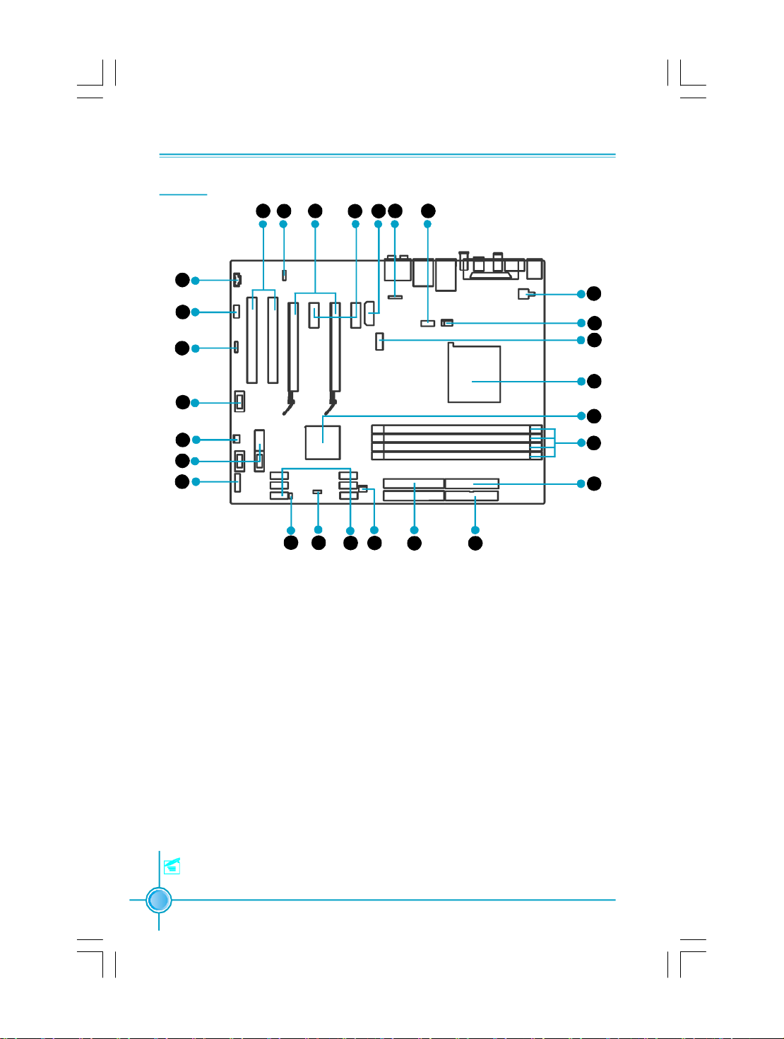
Layout
Chapter 1 Product Introduction
26
27
1
2
3
4
5
6
7
8
25
24
10
9
1.CD_IN Connector
2.Front Audio Connector
3.Speaker Connector
4.Front 1394 Connector(optional)
5.SYS_ FAN Connector
6.Front USB Connectors
7.Front Panel Connector
8.Chassis Intruder Connector
9.Clear CMOS Jumper
10.Serial ATA II Connectors
11.FAN Connector
12.ATA 133/100/66 IDE Connectors
13.FDD Connector
23
11
20 12 13
21
22
15.DDR2 DIMM Slots
16.nForce® 570 SLI MCP
17.Socket AM2
18.Serial ATA II Connector
19.CPU FAN Connector
20.4-pin ATX_12V Power Connector
21.COM1 Connector
22.IrDA Header
23.PWR3 Connector
24.PCI Exoress x1 Slots
25.PCI Express x16 Slots
26.SPDIF_OUT Connector
27.PCI Slots
14.24-pin ATX Power Connector
Note: The above motherboard layout is provided for reference only,
please refer to the physical motherboard.
4
18
17
24
16
15
14
20
19
26
Page 12

Chapter 1 Product Introduction
Rear I/O Ports
This motherboard provides the ports as below:
10 9
1
2
3
4 5 6
3
1. PS/2 Mouse Port
This port is used to connect a PS/2 mouse.
2. PS/2 Keyboard Port
This port is used to connect a PS/2 keyboard.
8
7
3. External SATA Port
This port is used to connect an external SATA box or a Serial ATA port multiplier
and enables smart setup and hot-plug function.
4. Coaxial S/PDIF Out Port
This port is used to connect an external audio output device via a coaxial S/P-
DIF cable.
5. Optical S/PDIF Out Port
This port is used to connect an external audio output device via a optical S/P-
DIF cable.
6. 1394a Port(optional)
This port is used to connect a 1394 device.
7. USB 2.0 Ports
The four ports are used to connect USB 2.0/1.1 devices.
5
Page 13
Chapter 1 Product Introduction
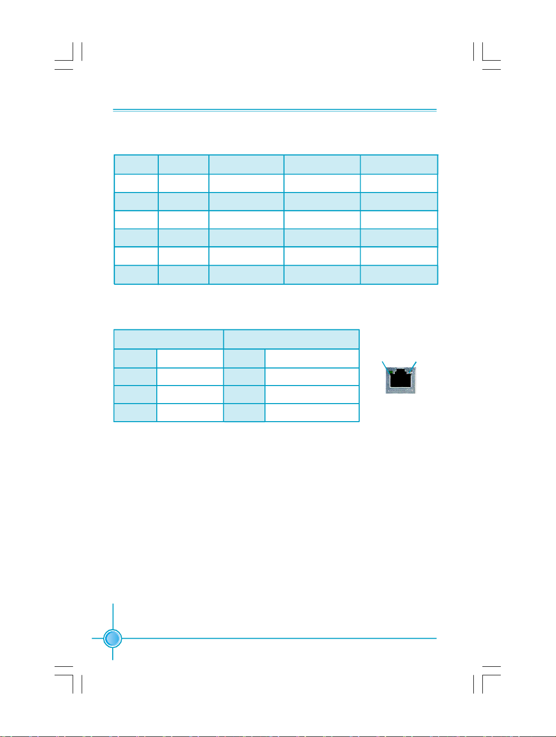
8. Line in, Line out, Microphone, Rear, LEF/CEN, Side Jacks
Port 2-channel 4-channel 6-channel 8-channel
Blue Line In Line In Line In Line In
Green Line Out Front Speaker Out Front Speaker Out Front Speaker Out
Pink Mic In Mic In Mic In Mic In
Orange - - Center/Subwoofer Center/Subwoofer
Black - Rear Speaker Out Rear Speaker Out Rear Speaker Out
Grey - - - Side Speaker Out
9. LAN Ports
Left : Link/Active LED Right: Speed LED
Status Description Status Description
Off No Link Off 10 Mbps Connection
Green Linked Green 100 Mbps Connection
Blinking Data Activity Orange 1 Gbps Connection
Link/Active
10. Parallel Port
The port is used to connect a parallel port device, such as a printer.
LED
LAN Port
Speed
LED
6
Page 14

Chapter 1 Product Introduction
Chapter
This chapter introduces the hardware installation process,
including the installation of the CPU, memory, power supply,
slots, and pin headers, and the mounting of jumpers. Cau-
tion should be exercised during the installation of these
modules. Please refer to the motherboard layout prior to
any installation and read the contents in this chapter carefully.
This chapter includes the following information:
2
2
v CPU
v Memory
v Power supply
v Other Connectors
v Expansion Slots
v Jumpers
7
Page 15

CPU
Chapter 2 Installation Instructions
This motherboard supports AMD Socket AM2 Athlon
64 FX, Athlon
TM
64 and SempronTM processors with HyperTransportTM Technology.
TM
64 X2 Dual-Core, Athlon
Attention:
The CPU pins must be properly aligned with the holes in the
socket, otherwise the CPU may be damaged.
For the detailed CPU vendor list qualified on this motherboard, please visit
the website: http://www.foxconnchannel.com
Installation of CPU
Follow these steps to install the CPU.
1.Unlock the socket by pressing the le-
ver sideways, then lift it up to a 90
o
angle.
o
90
Gap in the base
TM
2.Align the cut edge to the gap in the
base of the socket. Carefully insert the
CPU into the socket until it fits in place.
3.When the CPU is in place, press it
firmly on the socket while you push
down the socket lever to secure the
CPU. The lever clicks on the side tab
to indicate that it is locked.
8
Cut edge
Push down the socket
lever to secure the CPU.
Page 16

Chapter 2 Installation Instructions
Installation of CPU Fan
New technology allows processors to run at higher and higher frequencies.
To avoid problems arising from high-speed operation, for example, overheating, you need to install the proper fan. The following procedure is provided
for reference only, please refer to your CPU fan user guide for the actual
procedure.
CPU Fan
CPU Heatsink
CPU Retention
Mechanism
CPU Retention Bracket
CPU Retention Lock
1.Locate the CPU retention mecha-
nism base (surrounds the CPU
socket).
2.If required, apply a light coating of
silica gel to the top of the CPU.
NOTE: The CPU heatsink may have
a pre-applied thermal compound. In
that case, the silica gel is not required.
9
Page 17
Chapter 2 Installation Instructions
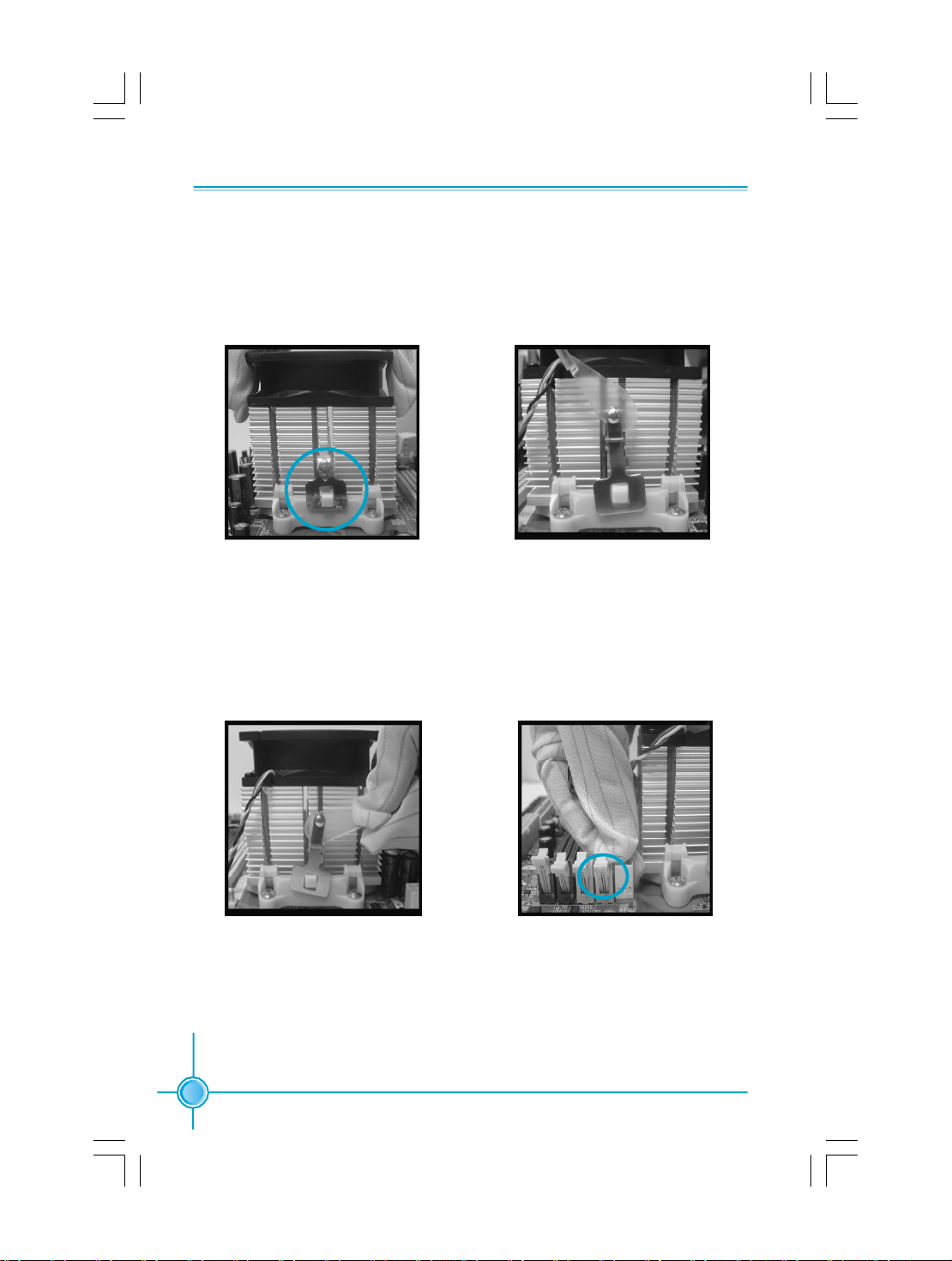
3. Place the cooling set onto the re-
tention mechanism. Attach one end
of the retention bracket to retention
mechanism.
5.Push down the retention bracket
lock on the retention mechanism
to secure the heatsink and fan to
module base.
4.Align the other end of the reten-
tion bracket to fasten the cooling
set on the top of the retention
mechanism.
6.Connect the fan’s power cable to
the appropriate 4-pin terminal on the
motherboard.
10
Page 18

Chapter 2 Installation Instructions
Memory
This motherboard includes four 240-pin slots with 1.8V for DDR2. These slots
support 256 Mb, 512 Mb and 1 Gb DDR2 technologies for x8 and x16 devices, and
support dual channel DDR2 memory technology up to 10.7GB/s. You must install
at least one memory bank to ensure normal operation.
Recommended Memory Configurations
The following table list is the recommended memory configurations. Please
install the memory according to the list.
Mode DIMM1 DIMM2 DIMM3 DIMM4
Populated
Populated
Populated
Single Channel
Dual Channel
Populated
Populated
Populated
Populated
Populated Populated
Populated
Populated
PopulatedPopulated
Populated
Populated
Populated
Populated
Populated
Populated
Populated
Installation of DDR2 Memory
1.There is only one gap near the center of the DIMM slot, and the memory
module can be fixed in one direction only. Unlock a DIMM slot by pressing the
module clips outward.
2.Align the memory module to the DIMM slot, and insert the module vertically
into the DIMM slot.
128 Pins
3.The plastic clips at both sides of the DIMM slot will lock automatically.
112 Pins
11
Page 19

Chapter 2 Installation Instructions
Warning :
Be sure to unplug the AC power supply before adding or removing
expansion cards or other system peripherals, especially the
memory devices, otherwise your motherboard or the system
memory might be seriously damaged.
For the detailed memory support list on this motherboard, please visit the
website: http://www.foxconnchannel.com
12
Page 20
Chapter 2 Installation Instructions
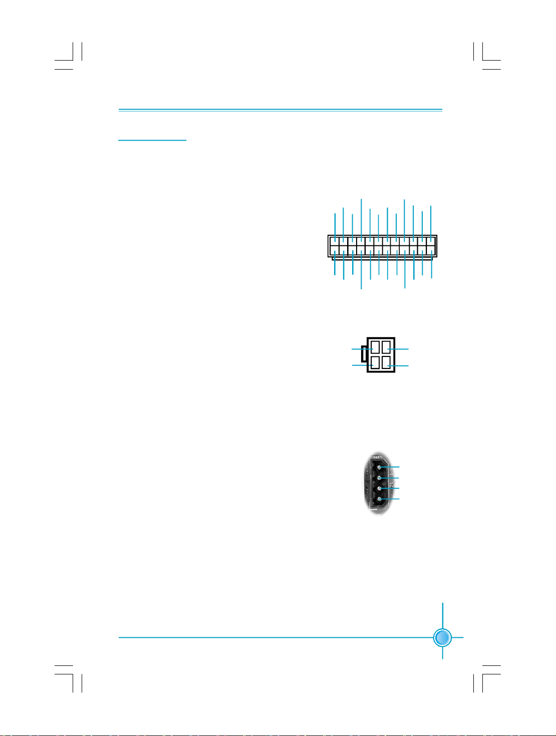
Power Supply
This motherboard uses an ATX power supply. In order to avoid damaging any
devices, make sure that they have been installed properly prior to connecting
the power supply.
+5V_AUX
+3.3V
+12V
GND
+5V
GND
PWROK
NC
+5V
+5V
+12V
+5V
GND
24-pin ATX power connector: PWR1
PWR1 is the ATX power supply connector. Make
sure that the power supply cable and pins are
properly aligned with the connector on the
motherboard. Firmly plug the power supply cable
into the connector and make sure it is secure.
+5V
+3.3V
GND
GND GND
-12V
PSON
GND
GND
1
13
+3.3V
+3.3V
PWR1
12
24
4-pin ATX_12 V Power Connector: PWR2
The 4-pin ATX 12V power supply connects to
PWR2 and provides power to the CPU.
Exclusive Graphics Power Connector: PWR3
This connector is a auxiliary power for graphics
card. Exclusive power for graphics card is for bet-
ter graphics performance and for future upgrade
usage.
3 1
12V
12V
4 2
GND
GND
PWR2
Exclusive Graphics Power Connector
4
1
+5V
GND
GND
+12V
13
Page 21

Chapter 2 Installation Instructions
Other Connectors
This motherboard includes connectors for FDD device, IDE devices, Serial ATA
devices, USB devices and others.
FDD Connector: FLOPPY
This motherboard includes a standard FDD connector, supporting 360K, 720K,
1.2M, 1.44M, and 2.88M FDDs.
IDE Connector: PIDE & SIDE
The IDE connector supports Ultra ATA 133/100/66 IDE hard disk drives. Con-
nect the cable’s blue connector to the IDE connector, then connect the gray
connector to the slave device (hard disk drive) and the black connector to the
Ultra ATA master device. If you install two hard disks, you must configure the
second drive as a slave device by setting its jumper accordingly. Refer to the hard
disk documentation for the jumper settings.
Attention:
Ribbon cables are directional, therefore, make sure to always
connect with the cable on the same side as pin 1 of the PIDE or
FLOPPY connector on the motherboard.
14
Page 22

Chapter 2 Installation Instructions
Front Panel Connector: FP1
This motherboard includes one connector for con-
necting the front panel switch and LED indicators.
PWRSW
RESET
FP1
Empty
NC
PWRLED
+ -
2 10
1
+ -
HDD-LED
9
HDD LED Connector (HDD-LED)
The connector connects to the case’s HDD indicator LED indicating the activity
status of hard disks.
Reset Switch (RESET)
Attach the connector to the Reset switch on the front panel of the case; the
system will restart when the switch is pressed.
Power LED Connector (PWRLED)
Attach the connector to the power LED on the front panel of the case. The Power
LED indicates the system’s status. When the system is in S0 status, the LED is
on. When the system is in S1, S3, S4, S5 status, the LED is off.
Power Switch Connector (PWRSW)
Attach the connector to the power button of the case. Pushing this switch allows
the system to be turned on and off rather than using the power supply button.
Audio Connector: F_AUDIO_1
The audio connector supports HD audio standard. It provides two kinds of
audio output choices: the Front Audio,
the Rear Audio. Front Audio supports
re-tasking function.
PORT1_L
PORT1_R
PORT2_R
SENSE_SEND
PORT2_L
1
2
9
10
F_AUDIO_1
AUD_GND
PRESENCE_J
SENSE1_RETURN
Empty
SENSE2_RETURN
15
Page 23

Chapter 2 Installation Instructions
Serial ATA II Connectors: SATA_1, SATA_2,
SATA_3, SATA_4, SATA_5, SATA_6,
The Serial ATA II connectors are used to connect
the Serial ATA II devices to the motherboard.
These connectors support the thin Serial ATA II
cables for primary storage devices. The current
Serial ATA II interface allows up to 300MB/s data
transfer rate.
The serial ATA II connectors support RAID 0,
RAID 1, RAID 0+1, RAID 5 Function.
Fan Connectors: CPU_FAN, SYS_FAN, FAN
The fan speed can be detected and viewed in
“PC Health Status” section of the CMOS Setup.
These fans will be automatically turned off after
the system enters S3, S4 and S5 mode.
RX+
RX-
TX-
TX+
+12VGND SENSE
1
GND
1
POWERCONTROL
GND
GND
GND
SATA _1/2/3/4/5/6
SYS-FAN
FAN
SENSE
CPU_FAN
1
USB Headers: F_USB1, F_USB2, F_USB3
Besides four USB ports on the rear panel, the
series of motherboards also have three 10-pin
headers on board which may connect to front
panel USB cable to provide additional six USB
ports.
Additional COM Connector: COM1
This motherboard provides an additional COM
header for your machine.
Connect one side of a switching cable to the
header, then attach the COM device to the other
side of the cable.
16
NC
GND
D+
D-
5V_DUAL
F_USB 1/2/3
2
1
2
DTR#
DSR# SIN
SOUT
910
Empty
D-
1
CTS#
Empty
GND RLSD RI#
RTS#
COM1
GND
D+
5V_DUAL
10
9
Page 24

Chapter 2 Installation Instructions
IEEE 1394a Connector: F_1394_1 (optional)
The 1394 expansion cable can be connected to either
the front (provided that the front panel of your chassis
is equipped with the appropriate interface) or real
panel of the chassis.
Speaker Connector: SPEAKER
The speaker connector is used to connect speaker of
the chassis.
Audio Connectors: CD_IN
CD_IN is Sony standard CD audio connectors, it can
be connected to a CD-ROM drive through a CD audio
cable.
Chassis Intruder Connector: INTR
The connector connects to the chassis security switch
on the case.The system can detect the chassis intrus-
ion through the status of this connector. If the connect-
or has been closed once, the system will send a mes-
sage. To utilize this function, set “Case Open Warning”
to “Enabled” in the “Power Management Setup” secti-
on of the CMOS Setup. Save and exit, then boot the op-
erating system once to make sure this function takes
effect.
F_1394_1
SPEAKER
CD_IN
INTR
910
TPB +
12
SPKJ
NC
Empty
+5V1
CD_L
GND
CD_R
Empty
+12V
TPA +
GND
+12V
TPB -
GND
TPA -
1
1 INTRUDERJ 2 GND
GND
IrDA Connector: IR
This header supports wireless transmitting and recei-
ving device. Before using this function, configure the s-
ettings of IR Mode from the “ Integrated Peripherals” s-
ection of the CMOS Setup.
S/PDIF-OUT Connector: SPDIF _OUT
The SPDIF OUT Connector is capable of providing dig-
ital audio to external speakers or compressed AC3 da-
ta to an external Dolby digital decoder.
1
IR
1
1
SPDIF_OUT
IRTX
GND
IRRX
Key
+5V
+5V
Empty
SPDIF_OUT
GND
17
Page 25

Chapter 2 Installation Instructions
Expansion Slots
This motherboard includes two 32-bit master PCI bus slots, two PCI Express
x1 slots, and two PCI Express x16 slots.
PCI Slots
The expansion cards can be installed in the two PCI slots. PCI slots support
cards such as a LAN card, USB card, SCSI card and other cards that comply
with PCI specifications.
PCI Express x1 Slots
This motherboard has Two PCI Express x1 slots that designed to accommo-
date less bandwidth-intensive cards, such as a modem or LAN card.
PCI Express x16 Slots
This motherboard has two PCI Express x16 slots that reserved for graphics or
video cards. The difference in bandwidth between the x16 and x1 slots is no-
table to be sure. This motherboard design enables the support of dual PCI-Ex-
press graphics cards technology such as “SLI technology” and multiple display.
For the detailed PCI Express x16 graphics cards support list on this
motherboard, please visit the website: http://www.foxconnchannel.com
18
Page 26

Chapter 2 Installation Instructions
Jumpers
The users can change the jumper settings on this motherboard if needed. This
section explains how to use the various functions of this motherboard by chang-
ing the jumper settings. Users should read the following content carefully prior to
modifying any jumper settings.
Description of Jumpers
1. For the jumpers on this motherboard, pin 1 can be identified by the bold
silk-screen next to it. However, in this manual, pin 1 is simply labeled as
“1”.
2. The following table provides some explanation of the jumper pin settings.
User should refer to this when adjusting jumper settings.
Jumper Diagram Definition Description
1
1
1
1
1
1
1-2 Set pin1 and pin2 closed
2-3 Set pin2 and pin3 closed
Closed Set the pin closed
Open Set the pin opened
Clear CMOS Jumper: CLR_CMOS
The motherboard uses the CMOS RAM to store all
the set parameters. The CMOS can be cleared by
removing the CMOS jumper.
NORMAL
(Default)
How to clear CMOS?
1. Turn off the AC power supply and connect pins 1
and 2 together using the jumper cap.
2. Return the jumper setting to normal (pins 2 and
3 together with the jumper cap).
3. Turn the AC power supply back on.
Warning:
1. Disconnect the power cable before adjusting the jumper settings.
2. Do not clear the CMOS while the system is turned on.
1 3 2
CLEAR
1 3 2
CLR_CMOS
19
Page 27

Chapter 3 BIOS Description
Chapter
20
3
3
This chapter tells how to change system settings through the
BIOS Setup menus. Detailed descriptions of the BIOS param-
eters are also provided.
You have to run the Setup Program when the following cases
occur:
1.An error message appears on the screen during the system
POST process.
2.You want to change the default CMOS settings.
This chapter includes the following information:
v Enter BIOS Setup
v Main Menu
v Standard CMOS Features
v Tiger Central Control Unit
v Advanced BIOS Features
v Advanced Chipset Features
v Integrated Peripherals
v Power Management Setup
v PnP/PCI Configurations
v PC Health Status
v Load Fail-Safe Defaults
v Load Optimized Defaults
v Set Supervisor/User Password
v Save & Exit Setup
v Exit Without Saving
Page 28

Chapter 3 BIOS Description
Enter BIOS Setup
The BIOS is the communication bridge between hardware and software,
correctly setting up the BIOS parameters is critical to maintain optimal system
performance. Power on the computer, when the following message briefly
appears at the bottom of the screen during the POST (Power On Self Test),
press <Del> key to enter the Award BIOS CMOS Setup Utility.
Press TAB to show POST Screen, DEL to enter SETUP, ESC to enter Boot Menu.
Note:
We do not suggest that you change the default parameters in the
BIOS Setup, and we shall not be responsible for any damage that
result from any changes that you make.
Main Menu
The main menu allows you to select from the list of setup functions and two exit
choices. Use the arrow keys to select among the items and press <Enter> to
accept or go to the sub-menu.
Main Menu
The items in the main menu are explained as below:
Standard CMOS Features
The basic system configuration can be set up through this menu.
Tiger Central Control Unit
The special features can be set up through this menu.
Advanced BIOS Features
The advanced system features can be set up through this menu.
21
Page 29

Chapter 3 BIOS Description
Advanced Chipset Features
The values for the chipset can be changed through this menu, and the system
performance can be optimized.
Integrated Peripherals
All onboard peripherals can be set up through this menu.
Power Management Setup
All the items of Green function features can be set up through this menu.
PnP/PCI Configurations
The system’s PnP/PCI settings and parameters can be modified through this
menu.
PC Health Status
This will display the current status of your PC.
Load Fail-Safe Defaults
The default BIOS settings can be loaded through this menu.
Load Optimized Defaults
The optimal performance settings can be loaded through this menu, however,
the stable default values may be affected.
Set Supervisor Password
The supervisor password can be set up through this menu.
Set User Password
The user password can be set up through this menu.
Save & Exit Setup
Save CMOS value settings to CMOS and exit setup.
Exit Without Saving
Abandon all CMOS value changes and exit setup.
22
Page 30

Chapter 3 BIOS Description
Standard CMOS Features
This sub-menu is used to set up the standard CMOS features, such as the date,
time, HDD model and so on. Use the arrow keys select the item to set up, and
then use the <PgUp> or <PgDn> keys to choose the setting values.
Standard CMOS Features Menu
Date
This option allows you to set the desired date (usually as the current day) with
the <day><month><date><year> format.
Day—weekday from Sun. to Sat., defined by BIOS (read-only).
Month—month from Jan. to Dec..
Date—date from 1st to 31st, can be changed using the keyboard.
Year—year, set up by users.
Time
This option allows you to set up the desired time (usually as the current time)
with <hour><minute><second> format.
IDE Channel 0 Master/Slave & IDE Channel 2/3/4/5/6/7 Master
While entering Setup, the BIOS automatically detects the presence of IDE dev-
ices.There is a sepatate sub-menu for each IDE device, select a device item
then press <Enter>to display the IDE information. The values opposite the
dimmed items (Capacity,Head,Sector,Cylinder, Precomp,Landing Zone) are
not user-configurable.These values show ”0” if no IDE device is installed in
the system.
Drive A
This option allows you to select the kind of FDD to be installed,including
“None”, [360K, 5.25 in], [1.2M, 5.25 in], [720K, 3.5 in], [1.44M, 3.5 in] and [2.88 M, 3.5
in].
23
Page 31

Chapter 3 BIOS Description
Halt On
This category determines whether or not the computer will stop if an error is
detected during powering up.
All Errors Whenever the BIOS detects a nonfatal error, the system
will stop and you will be prompted.
No Errors The system boot will not stop for any errors that may
be detected.
All, But Keyboard The system boot will not stop for a keyboard error; but
it will stop for all other errors.
All, But Diskette The system boot will not stop for a diskette error; but
it will stop for all other errors.
All, But Disk/Key The system boot will not stop for a keyboard or disk
error, but it will stop for all other errors.
Memory
This is a Display-Only Category, determined by POST (Power On Self Test) of
the BIOS.
Base Memory The BIOS POST will determine the amount of base (or
conventional) memory installed in the system.
Extended Memory The BIOS determines how much extended memory
is present during the POST.
Total Memory Total memory of the system.
24
Page 32

Chapter 3 BIOS Description
Tiger Central Control Unit
Tiger Central Control Unit Menu
v[Smart BIOS]
Smart Power LED
Smart debug LED function within power LED. Enable this function, the power
LED status can show the system status of POST process.
System Status Power LED Status
Normal on
No CPU Fan blinking once (blinking 0.5 sec., off 0.5 sec.)
No Display blinking once (blinking 2 sec., off 2 sec.)
No Memory blinking twice
Post Error Message blinking thrice
Smart Boot Menu
Smart boot menu with a timer to let user to control boot device easily.
vAuto Detect PCI Clk
This option is used to set whether the clock of an unused PCI slot will be
disabled to reduce electromagnetic interference. The setting values are
Disabled and Enabled.
vDRAM Configuration
Press Enter to set the items of DRAM Configuration.
vPCIE clock
This option is used to set PCIE overclock function.
vTiger Intelligent Stepping
User can select different overclocking option by this item. The available setting values are: Manual, Auto, Power gaming, Data Mining, Office, Energy
Saving.
25
Page 33

Chapter 3 BIOS Description
vCPU Frequency
This option is used to set CPU Frequency.
vCPU Clock Multiplier
This option is used to set CPU Clock Multiplier.
vAMD K8 Cool& Quiet Control
This option is used to control AMD K8 Cool&quiet Technology.
v PCIE Spread Spectrum
If you enable PCIE spread spectrum, it can significantly reduce the EMI (ElectroMagnetic Interference) generated by PCIE. The setting values are Disabled
and Enabled.
vSATA Spread Spectrum
If you enable SATA spread spectrum, it can significantly reduce the EMI (ElectroMagnetic Interference) generated by SATA. The setting values are Disabled
and Enabled.
vHT Spread Spectrum
If you enable HT spread spectrum, it can significantly reduce the EMI (ElectroMagnetic Interference) generated by HT. The setting values areDisabled
and Enabled.
vCPU Vcore Over Voltage Setting
This option is used to set CPU Vcore over voltage.
vDRAM Voltage Select
This option is used to set the DRAM voltage.
vChipset Voltage Select
This option is used to set the Chipset voltage.
vLDT Voltage Select
This option is used to set the LDT voltage.
26
Page 34

Chapter 3 BIOS Description
DRAM Configuration Menu
vTiming Mode
This option is used to set timing mode.
vDQS Training Control
This option controls the DQS training .
vCKE base Power down mode
This option is used to set the CKE base Power dowm mode.
vCKE based Powerdowm
This option controls the CKE based power down.
vMemory hole Remapping
This option is used to enalbe or disable the memory hole remapping.
vAuto Optimize Bottom IO
This option is used to set the auto optimize bottom IO.
vBottom of [31:24] IO space
This option is used to set Bottom of [31:24] IO space.
27
Page 35

Chapter 3 BIOS Description
Advanced BIOS Features
Advanced BIOS Features Menu
vBIOS ROM Protect
This option is used to enable or disable BIOS ROM Protect function.
vBootBlock Protect
This option is used to enable or disable BootBlock Protect function.
vRemovable Device Priority
This option is used to remove the priority for removable device startup. After
pressing <Enter>, you can remove the removable device using the <PageUp>/
<PageDn> or Up/Down arrow keys, and change the removable device prior-
ity using <+> or <->. To exit this option, press <Esc>.
vHard Disk Boot Priority
This option is used to select the priority for HDD startup. After pressing
<Enter>, you can select the HDD using the <PageUp>/<PageDn> or Up/Down
arrow keys, and change the HDD priority using <+> or <->. To exit this option,
press <Esc>.
vCD-ROM Boot Priority
This option is used to select the priority for CD-ROM startup. After pressing
<Enter>, you can select the CD-ROM using the <PageUp>/<PageDn> or Up/
Down arrow keys, and change the CD-ROM priority using <+> or <->. To exit
this option, press <Esc>.
vNetwork Boot Priority
This option is used to select the priority for network boot startup. After press-
ing <Enter>, you can select the network boot using the <PageUp>/<PageDn>
or Up/Down arrow keys, and change the network boot priority using <+> or <
->. To exit this option, press <Esc>.
28
Page 36

Chapter 3 BIOS Description
vVirus Warning
This option is used to set up the virus warning message for the IDE HDD boot
sector. When enabled, a warning message will appear on the screen if any
program intends to write information to the boot sector.
Note: Such function provides protection to the startup sector only; it does not
protect the entire hard disk.
vCPU Internal Cache
This option is used to turn on or off the CPU L1 and L2 cache.
vExternal Cache
This option is used to turn on or off the CPU external cache. The available
setting values are: Disabled and Enabled. Leave this item at the default value
for better performance.
vFirst/Second/Third Boot Device
This option allows you to set the boot device sequence. The available setting
values are: Floppy, LS120, Hard Disk, CDROM, ZIP100, USB-FDD, USB-ZIP,
USB-CDROM, Legacy LAN, NVIDIA Boot Age and Disabled.
vBoot Other Device
With this item enabled, the system will search all other possible locations if it
fails to find one in the devices specified under the first, second and third boot
devices.
vBoot Up Floppy Seek
If this option is enabled, BIOS will activate the floppy drive during the system
boot and the drive’s indicator will flash after the activation. The magnetic
head will move back and forth from A to B.
vBoot Up NumLock Status
This option defines if the keyboard Num Lock key is active when your system
is started.
vTypematic Rate Setting
If this option is enabled, you can use the following two items to see the typematic
rate and the typematic delay settings for your keyboard.
vTypematic Rate (Chars/Sec)
Use this option to define how many characters per second a held-down key
generated.
29
Page 37

Chapter 3 BIOS Description
vTypematic Delay (Msec)
Use this option to define how many milliseconds must elapse before a held-
down key begins generating repeat characters.
vSecurity Option
When it is set to “Setup”, a password is required to enter the CMOS Setup
screen; When it is set to “System”, a password is required not only to enter
CMOS Setup, but also to start up your PC.
vAPIC Mode
This option is used to enable or disable APIC function.
vFull Screen LOGO Show
This option allows you to enable or disable the full screen logo. The available
setting values are: Disabled and Enabled.
vSmall Logo (EPA) Show
This option allows you to enable or disable the EPA logo. The available setting
values are: Disabled and Enabled.
30
Page 38

Chapter 3 BIOS Description
Advanced Chipset Features
Advanced Chipset Features Menu
vPMU
This option is used to enable or disable PWU function.
vK8<->SB HT Speed
These options are used to set the bandspeed of the link’s transmitter of K8
<->SB.
vK8<->MCP55 HT Width
These options are used to set the bandwidth of the link’s transmitter of K8
<->MCP55.
vSSE/SSE2 Instructions
It is used to set enable or disable Intel SSE/SSE2 instructions.
vSystem BIOS Cacheable
Select “Enabled” to allow catching of the system BIOS which may improve per-
formance. If any other program writes to this memory area, a system error
may result.
31
Page 39

Integrated Peripherals
Integrated Peripherals Menu
vIDE Function Setup
Press enter to set IDE Function Setup.
vOnboard Device
Press enter to set Onboard Device.
vOnboard Super IO
Press enter to set Onboard Super IO.
Chapter 3 BIOS Description
32
Page 40

Chapter 3 BIOS Description
IDE Function Setup Menu
v RAID Config
Press <Enter> to set the items of RAID configuration function.
vOnChip IDE Channel 0
This option is used to set the onchip IDE channel 0. The available settings
are: Disabled and Enabled.
vPrimary Master/Slave PIO
These two items let you assign which kind of PIO (Programmer Input/Output)
is used by IDE devices. Choose “Auto” to let the system auto detect which PIO
mode is best, or select a PIO mode from 0-4.
vPrimary Master/Slave UDMA
UDMA technology provides faster access to IDE devices. If you install a device
that supports UDMA, change the appropriate items on this list to Auto. The
available setting values are: Disabled and Auto.
vIDE DMA transfer access
This option is used to enable or disable IDE DMA transfer access.
vSerial-ATA Controller
This option is used to enable or disable Serial-ATA cotroller.
vIDE Prefetch Mode
This option is used to enable or disable IDE prefetch mode.
vIDE HDD Block Mode
This option is used to set whether the IDE HDD block mode is allowed.
33
Page 41

Chapter 3 BIOS Description
RAID Config Menu
vRAID Enable
This item is available for you to enable or disable the onboard RAID functi-
on.
vSATA 1/2/3 Primary/Secondary
These features allow user to enable or disable the RAID function for each
SATA hard disk drive.
34
Page 42

Chapter 3 BIOS Description
Onboard Device Menu
vOnchip USB
This option is used to set whether the USB Controller is enabled.
vUSB Memory Type
This option is used to set the USB Memory type.
vUSB Keyboard Support
This option is used to set whether the USB keyboard controller is enabled in a
legacy operating system (such as DOS). The available setting values are: Dis
abled and Enabled.
vUSB Mouse Support
This option is used to set whether the USB mouse controller is enabled in a
legacy operating system (such as DOS). The available setting values are: Dis
abled and Enabled.
vHD Audio
This option is used to set whether onboard AC97 Audio is enabled. The avail
able setting values are: Disabled and Auto.
vMAC / MAC1 LAN
This option is used to set whether MAC LAN device is enalbed.
vMAC / MAC1 Media Interface
This option is used to set MAC Media Interface.
vMAC LAN Boot ROM
This option is used to decide whether to invoke the boot ROM of the MAC LAN
chip.
35
Page 43

Chapter 3 BIOS Description
Onboard SuperIO Menu
v Onboard FDC Controller
This option is used to set whether the Onboard FDC Controller is enabled.
The available setting values are: Disabled and Enabled.
vOnboard Serial Port 1
This option is used to assign the I/O address and interrupt request (IRQ) for
the onboard serial port 1.
vIrDA IO/IRQ Select
Use this option to select the IO/IRQ mode. The setting value is determined by
the infrared module installed on the board.
vIrDA Duplex Mode
This item enables you to determine the infrared function of the onboard infrared
chip.
vOnboard Parallel Port
This option allows you to determine onboard parallel port controller I/O ad-
dress and interrupt request (IRQ). The setting values are: Disabled, 378/IRQ7,
278/IRQ5 and 3BC/IRQ7.
vParallel Port Mode
Select an address and corresponding interrupt for the onboard parallel port.
The setting values are: SPP, EPP, ECP, ECP+EPP.
vECP Mode Use DMA
When the Parallel Port Mode is set to ECP or ECP+ EPP, this option is used to
select the channel for the ECP mode. The setting values are: 1 and 3.
36
Page 44

Chapter 3 BIOS Description
Power Management Setup
Power Management Setup Menu
vACPI function
ACPI stands for “Advanced Configuration and Power Interface”. ACPI is a
standard that defines power and configuration management interfaces be-
tween an operating system and the BIOS. In other words, it is a standard that
describes how computer components work together to manage system
hardware. In order to use this function the ACPI specification must be supp-
orted by the OS (for example, Windows2000 or WindowsXP). The available
setting values are: Enabled and Disabled.
v ACPI Suspend Type
This option is used to set the energy saving mode of the ACPI function.
When you select “S1 (POS)” mode, the power will not shut off and the
supply status will remain as it is, in S1 mode the computer can be resumed
at any time. When you select “S3 (STR)” mode, the power will be cut off after
a delay period. The status of the computer before it enters STR will be saved
in memory, and the computer can quickly return to previous status when the
STR function wakes. When you select “S1 & S3” mode, the system will
automatically select the delay time.
vPower Management
This option is used to set the power management scheme. Available settings
are: User Define, Min Saving and Max Saving.
37
Page 45

Chapter 3 BIOS Description
v Video Off Method
This option is used to define the video off method. “Blank Screen” mode
means that after the computer enters power saving mode, only the monitor
will close, however, the vertical and horizontal scanning movement of the screen
continues. When you select the “V/H SYNC + Blank” mode the vertical and horizontal
scanning movement of screen stops when the computer enters power saving
mode. “DPMS Supported” mode is a new screen power management system,
and it needs to be supported by the monitor you’re using.
v HDD Power Down
This option is used to turn off hard disk power if the hard disk is idle for a given
period of time. The setting values are Disabled and 1Min-15Min.
vHDD Down In Suspend
This option is used to define the continuous HDD idle time before the HDD
enters power saving mode. The setting values are Disabled and Enabled.
vSoft-Off by PBTN
This option is used to set the power down method. This function is only valid
for systems using an ATX power supply. When “Instant-Off” is selected, press
the power switch to immediately turn off power. When “Delay 4 Sec.” is selecte-
d, press and hold the power button for four seconds to turn off power.
vWOL(PME#) From Soft-Off
When set to Enable, the feature allows your system to be awakened from the
power saving modes through any event on PME (Power Management Event)
vWOR(RI#) From Soft-Off
If this item is enabled, it allows the system to resume from a software power
down or power saving mode whenever there is an incoming call to an install-
ed fax/modem. This function needs to be supported by the relevant hardware
and software.
vUSB Resume From S3
This item is used to set the system to wake up by USB equipment when it is
in S3 (Suspend to RAM) mode.
38
Page 46

Chapter 3 BIOS Description
vPower-On by Alarm
This option is used to enable or disable the feature of booting up the system
on a scheduled time/date. The setting values are Disabled and Enabled.
vDate of Month Alarm
When the Power-On by Alarm set as “Enabled”, this option will be modified. It
is used to set the timing for the start-up date. The setting values contain 0 - 31.
vTime (hh: mm: ss) Alarm
When the Power-On by Alarm set as “Enabled”, this option will be modified. It
is used to set the timing for the start-up date. The setting values contain hh: 0-
23; mm: 0-59; ss: 0-59
vCase Open Warning
This option is used to enable or disable case open warning function.
vPOWER ON Function
This option is used to set the power on method for your PC. Setting values
include: Any KEY, Mouse Click, Both, BUTTON ONLY.
v PWRON After PWR-Fail
This item is used to set what action the PC will take with the power supply
when it resumes after a sudden power failure. The available options are: Off
(remain in turn off status), On (auto power on) and Former-Sts (resume with
the previ-ous status).
39
Page 47

Chapter 3 BIOS Description
PnP/PCI Configurations
PnP/PCI Configurations Menu
vReset Configuration Data
This option is used to set whether the system is permitted to automatically
distribute IRQ DMA and I/O addresses when each time that the machine is
turned on. The setting values are: Disabled and Enabled.
vResouces Controlled By
This option is used to define the system resource control scheme. If all cards
you use support PnP, then select Auto (ESCD) and the BIOS will automatically
distribute interruption resources. If the ISA cards you installed not support-
ing PnP, you will need to select “Manual” and manually adjust interruption
resources in the event of hardware conflicts. However, since this motherboard
has no ISA slot, this option does not apply.
vIRQ Resources
Press the <Enter> key, then manually set IRQ resources.
vPCI/VGA Palette Snoop
If you use a non-standard VGA card, use this option to solve graphic accelera-
tion card or MPEG audio card problems (e.g., colors not accurately displayed).
The setting values are: Disabled and Enabled.
vInit Display First
This option is used to set which display device will be used first when your PC
starts up.
vMaximum Payload Size
This option is used to set maximum TLP payload size for PCI Express devices.
The unit is byte.
40
Page 48

Chapter 3 BIOS Description
PC Health Status
PC Health Status Menu
vShutdown Temperature
This option is used to set the system temperature upper limit. When the
temperature exceeds the setting value, the motherboard will automatically cut
off power to the computer.
vVCC 3.3/Vcore/1.8V/1.5V/+5V/+12V/VSB3.3/Voltage Battery
The current voltages will be automatically detected by the system.
vCurrent CPU/System Temperature
The current system/CPU temperature will be automatically detected by the
system.
vSYSTEM/CPU/FAN1 FAN
The system/CPU fan speed will be automatically detected by the system.
vSmart FAN1 Mode Control
This option is used to enable or disable smart fan function. “PWM Mode” can
enable smart fan function.
vSmart FAN1 PWM 0
This option is used to set smart fan1 PWM 0.
vSmart FAN1 T 1
This option is used to set smart fan1 temperature 1 value.
vCPU Average Current
This option is used to set CPU current status.
41
Page 49

Chapter 3 BIOS Description
Load Fail-Safe Defaults
Press <Enter> to select this option. A dialogue box will pop up that allows you to
load the default BIOS settings. Select <Y> and then press <Enter> to load the
defaults. Select <N> and press <Enter> to exit without loading. The defaults set by
BIOS set the basic system functions in order to ensure system stability. But if
your computer cannot POST properly, you should load the fail-safe defaults to
restore the original settings. Then carry out failure testing. If you only want to
load the defaults for a single option, you can select the desired option and
press the <F6> key.
Load Optimized Defaults
Select this option and press <Enter>, and a dialogue box will pop up to let you
load the optimized BIOS default settings. Select <Y> and then press <Enter> to
load the optimized defaults. Select <N> and press <Enter> to exit without loading.
The defaults set by BIOS are the optimized performance parameters for the
system, to improve the performance of your system components. However, if
the optimized performance parameters are not supported by your hardware
devices, it will likely cause system reliability and stability issues. If you only want
to load the optimized default for a single option, select the desired option and
press the <F7> key.
Set Supervisor/User Password
The access rights and permissions associated with the Supervisor password are
higher than those of a regular User password. The Supervisor password can be
used to start the system or modify the CMOS settings. The User password can
also start the system. While the User password can be used to view the current
CMOS settings, these settings cannot be modified using the User password.
When you select the Set Supervisor/User Password option, the following message
will appear in the center of the screen, which will help you to set the password:
Enter Password:
Enter your password, not exceeding 8 characters, then press <Enter>. The
password you enter will replace any previous password. When prompted, key in
the new password and press <Enter>.
42
Page 50

Chapter 3 BIOS Description
If you do not want to set a password, just press <Enter> when prompted to enter
a password, and in the screen the following message will appear. If no password
is keyed in, any user can enter the system and view/modify the CMOS settings.
Password Disabled!!!
Press any key to continue …
Under the menu “Advanced BIOS Features”, if you select “ System” from the
Security Option, you will be prompted to enter a password once the system is
started or whenever you want to enter the CMOS setting program. If the incorrect
password is entered, you will not be permitted to continue.
Under the menu “Advanced BIOS Features”, if you select “Setup” from the Secu-
rity Option, you will be prompted to enter a password only when you enter the
CMOS setting program.
Save & Exit Setup
When you select this option and press <Enter>, the following message will
appear in the center of the screen:
SAVE to CMOS and EXIT (Y/N)?Y
Press <Y> to save your changes in CMOS and exit the program; press <N> or
<ESC> to return to the main menu.
Exit Without Saving
If you select this option and press <Enter>, the following message will appear
in the center of the screen:
Quit Without Saving (Y/N)?N
Press <Y> to exit CMOS without saving your modifications; press <N> or <ESC>
to return to the main menu.
43
Page 51

Chapter 4 Driver CD Introduction
Chapter
The utility CD that came with the motherboard contains useful
software and several utility drivers that enhance the motherboard
features.
This chapter includes the following information:
v Installing Utilities
4
4
v Utility CD content
v Installing Drivers
44
Page 52

Chapter 4 Driver CD Introduction
Utility CD content
This motherboard comes with one Utility CD. To begin using the CD, simply
insert the CD into your CD-ROM drive. The CD will automatically displays the
main menu screen.
1. Driver
Using this choice, you can install all the drivers for your motherboard. You should
install the drivers in order and you need to restart your computer after the drivers
all installed.
A. NVIDIA Chipset Driver B. Realtek HDA Audio Driver
C. JMB RAID Driver
2. Utility
Use this option to install additional software programs.
A.TIGER ONE
B.Fox LiveUpdate
C.Microsoft DirectX 9.0
D. Adobe Acrobat Reader
E. Create RAID Driver Floppy
3.Click on static WinFast logo to visit our homepage.
45
Page 53

Chapter 4 Driver CD Introduction
Installing Divers
There are two ways to install drivers, manual or auto. Click the drivers that you
want to install and begin the setup steps by manual. Or you just click “One Click
Setup” button to install the drivers by auto after install Intel Chipset Driver.
Install by manual
Install by auto
Installing Utilities
You can select the utilities that you want to install and begin the setup steps.
46
Click here
Page 54

Chapter 4 Driver CD Introduction
Chapter
This chapter will introduce how to use attached software.
This chapter provides the following information:
5
5
v TIGER ONE
v Fox LiveUpdate
47
Page 55

Chapter 5 Directions for Bundled Software
TIGER ONE
TIGER ONE is a powerful utility for easily modifying system settings. It also
allows users to monitor various temperature values, voltage values, frequency
and fan speed at any time.
With TIGER ONE, you can
-Modify system performance settings, such as bus speeds, CPU voltages,
fan speed, and other system performance options that are supported by the
BIOS
-Monitor hardware temperature, voltage, frequency and fan speed
Supported Operating Systems:
-Windows 2000
-Windows XP (32-bit and 64-bit)
-Windows 2003 (32-bit and 64-bit)
Using TIGER ONE:
1. Main Page
48
Show CPU
Information
Toolbar
Monitor Frequency/Voltage/Fan
speed/Temperature value
Alert Lamp
Switch
Button
Exit
Minimum
Configuration
Homepage
Page 56

Chapter 5 Directions for Bundled Software
Toolbar
Use the toolbar to navigate to other pages.
Alert Lamp
When the system is in healthy status, the alert lamp color is green. When the
system is in abnormal status, the alert lamp color is red.
Switch Button
Click this button, it will shorten to below figure. It helps you to minitor your
system healthy status at any time.
Click here to return to
previous status
Exit
Click this button to exit the program.
Minimum
Click this button to minimize the window.
Configuration
Click this button to configurate the parameters for the program. It determines
which items will be shown in shorten mode.
Homepage
Click this button to visit Foxconn motherboard website.
2. CPU Page - CPU Control
This page lets you select and run the TIGER ONE developed benchmarks to
determine the current performance level of the system. You can also adjust by
manual. Only this page is set to Manual Adjustment, the Freq., Vlotage, and Fan
pages can be adjusted by manual.
49
Page 57

Chapter 5 Directions for Bundled Software
Go to CPU page
Close this page
Ajust by manual
Reset the
changes
Select the different
benchmarks
Apply the
changes
3. Freq. Page - Frequency Control
This page lets you set memory and PCI Express frequency by manual.
Go to Freq. page
Close this page
Select the option
you want to set
Adjust by manual
Reset the changes Apply the changes
50
Page 58

Chapter 5 Directions for Bundled Software
4.1 Limit Setting - CPU Temp.
This page lets you to set CPU high limit temperature and enable the alert
function.
Show current CPU
Go to Adjust page
temperature value
Enable alert function
when the CPU
temperature is higher
than high limit value
Show current high
limit value of CPU
temperature
Set high limit by
dragging the lever
4.2 Limit Setting - Sys Temp.
This page lets you to set system high limit temperature and enable the alert
function.
Show current system
temperature value
Set high limit by
dragging the lever
Enable alert function
when the system
temperature is higher
than high limit value
Show current high
limit value of system
temperature
51
Page 59

Chapter 5 Directions for Bundled Software
4.3 Limit Setting - CPU Fan
This page lets you to set CPU fan low limit rpm and enable the alert function.
Show current CPU
fan rpm value
Enable alert function
when the CPU fan rev
is lower than low limit
rpm value
Show current low limit
rpm value of CPU fan
Set low limit rpm by
dragging the lever
4.4 Limit Setting - Sys Fan
This page lets you to set system low limit rpm and enable the alert function.
52
Show current system
fan rpm value
Enable alert function
when the system fan
is lower than low limit
rpm value
Show current low limit
rpm value of system fan
Set low limit rpm by
dragging the lever
Page 60

Chapter 5 Directions for Bundled Software
4.5 Limit Setting - FAN1 Fan
This page lets you to set FAN1 Fan low limit rpm and enable the alert function.
Show current FAN1
Fan rpm value
Enable alert function when
the FAN1 Fan is lower
than low limit rpm value
Show current low limit
rpm value of FAN1 Fan
Set low limit rpm by
dragging the lever
5. Voltage Page - Voltage Control
This page lets you set CPU voltage, memory voltage and North Bridge voltage
by manual.
Go to Voltage page
Reset the changes Apply the changes
Select the option
you want to set
Adjust by manual
53
Page 61

Chapter 5 Directions for Bundled Software
6. Fan Page - Fan Control
This page lets you enable smart Fan function or set fan speed by manual.
Go to Fan page
Enable or disable
smart fan function
Set fan speed by
dragging the lever
Reset the changes
Apply the changes
54
Page 62

Chapter 5 Directions for Bundled Software
Fox LiveUpdate
Fox LiveUpdate is a useful utility for backuping and updating the system BIOS,
drivers and utilities by local or online.
Supported Operating Systems:
-Windows 2000
-Windows XP (32-bit and 64-bit)
-Windows 2003 (32-bit and 64-bit)
Using Fox LiveUpdate:
1.1 Local Update - BIOS Info.
This page lets you know your system BIOS information.
Toolbar
Link to website
Minimum
Exit
Show current
BIOS information
55
Page 63

Chapter 5 Directions for Bundled Software
1.2 Local Update - Backup
This page lets you backup your system BIOS. Click “Backup”, then give a name.
Click “Save” to finish the backup operation.
Key in a BIOS name
Click here
1.3 Local Update - Update
This page lets you update your system BIOS from Internet. After click “Update”,
there will show warning message, please read it carefully. If you still want to
continue, click “Yes”. Then load a local BIOS file and follow the wizard to finish
the operation.
56
Note:
Fox LiveUpdate will auto backup BIOS before update because
we have enabled this function in Configure option.
Page 64

Chapter 5 Directions for Bundled Software
2.1 Online Update - Update BIOS
This page lets you update your system BIOS from Internet. Click “start”, it will
search the new BIOS from Internet. Then follow the wizard to finish the update
operation.
Click here
Current information
Search new BIOS
from Internet
Select BIOS to update
Browse detail
information
Update BIOS
Close the window
57
Page 65

Chapter 5 Directions for Bundled Software
2.2 Online Update - Update Driver
This page lets you update your system drivers from Internet. Click “start”, it will
search the new drivers from Internet. Then follow the wizard to finish the update
operation.
Click here
Current information
Search new drivers
from Internet
Select the drivers to update
58
Browse detail
information
Install the selected
drivers
Close the window
Page 66

Chapter 5 Directions for Bundled Software
2.3 Online Update - Update Utility
This page lets you update utilities from Internet. Click “start”, it will search the new
utilities from Internet. Then follow the wizard to finish the update operation.
Click here
Current information
Search new utilities
from Internet
2.4 Online Update - Update All
This page lets you update your system drivers from Internet. Click “start”, it will
search all new BIOS/drivers/utilities from Internet. Then follow the wizard to finish
the update operation.
Click here
Current information
Search all new
BIOS/drivers/utilities
from Internet
59
Page 67

Chapter 5 Directions for Bundled Software
3.1 Configure - option
This page lets you set auto search options. After your setting, the utility will
start searching and related information will show on the task bar.
Click here
Set auto
search options
Select search
which kind of
versions
Apply the changes Reset to default value
Note:
60
When enable auto search function, Fox LiveUpdate will appear
searching result on task-bar. Double click the icon, you can see the
detail information.
Double click here
Page 68

Chapter 5 Directions for Bundled Software
3.2 Configure - System
This page lets you set the backup BIOS location and change different skin of
the utility.
Click here
Set the location of
download files or
auto backup BIOS
Select different skin
of the software
Determine if the Fox
LiveUpdate can auto run
when the system starts up
Apply the changes
Reset to default value
4. About & Help
This page shows some information about Fox LiveUpdate.
Click here
Show information
about Fox LiveUpdate
61
Page 69

Appendix
NVIDIA SLITM Technology
1. Introduction
NVIDIA® SLITM (Scalable Link Interface) technology takes advantage of the increased
bandwidth of the PCI ExpressTM bus architecture, and features intelligent hardware
and software solutions to deliver earth-shattering PC performance in a multi NVIDIA
GPU solution.
NVIDIA® nForceTM5 SLI MCPs (media and communications processors) offer blister-
ing graphics performance and overall PC performance for both AMD and Intel
platforms. With the power of SLITM technology you get the ability to connect two NVIDIA
SLI-Ready PCI ExpressTM graphics cards for mind-blowing game play with brilliant
and intensive 3D graphics.
2. Using SLI
Step1. Install two SLI-Ready Graphic cards on the two PCI Express x16 slots.
TM
Technology
62
Page 70

Appendix
Step2. Connect power extension cable to the graphics card power connector and
power supply connector.
Power Extension
cable
Step 3. Install the SLI Bridge Board to the goldfingers on each graphics card. Make
sure that the connector is firmly in place.
Step 4. Connect the 4-pin ATX power cable to the Auxiliary power connector to secure
the system is stable.
Step 5. Power on your computer and boot into Operating System.
Step 6. Install the NVIDIA graphics card drivers and restart your computer.
63
Page 71

Appendix
Step 7. Right-click the mouse --> Select “Properties”--> Select “Setting” --> Click
“Advanced” --> Select “GeForce xxxx xxx” --> Click “SLI multi-GPU” --> Click “Enable
SLI multi-GPU”.
64
Page 72

Appendix
NVIDIA RAID
RAID Arrays
This section describes the following types of RAID arrays that NVIDIA RAID
supports:
v RAID 0
RAID 0 defines a disk striping scheme that improves the disk read and write
times for many applications.
vRAID 1
RAID 1 defines techniques for mirroring data.
vRAID 0+1
RAID 0+1 combines the techniques used in RAID 0 and RAID 1 arrays.
vRAID 5
RAID 5 provides fault tolerance and better utilization of disk capacity.
vSpanning (JBOD)
JBOD provides a method for combining drives of different sizes into one large
disk.
Summary of RAID Configurations
Array
RAID 0
RAID 1
RAID
0+1
RAID 5
JBOD
Advantages
High data throughput.
100% data redund-
ancy.
Optimized for both
100% data redun-
dancy and per-
formance. Allows
spare disks.
Fault tolerance and
better utilization of disk
space.
ombines and uses the
capacity of odd size
drives.
Drawbacks
No fault tolerance.
Requires two drives
for the storage space
of one drive.
Requires two drives
for the storage space
of one drive - the same
as RAID level 1.
Decreased write per-
formance due to parity
calculations.
Decreases perfor-
mance because of the
difficulty in using drives
concurrently or to op-
timize drives for differ-
ent uses.
# Hard Disks
multiple
2
4+
3+
multiple
Fault Tolerance
None
Yes
Yes
Yes
No
65
Page 73

Appendix
Additional RAID Features
NVIDIA RAID offers the following additional features:
vFree Disk and Dedicated Spare Disk
A Free Disk or Dedicated Disk can be automatically used in case one drive of a
fault-tolerant array fails. NVIDIA RAID defines a fault-tolerant array as either
RAID 1, RAID 0+1, or RAID 5. A free disk can be used by any available fault-
tolerant array, while a dedicated disk can be used only by the array to which it is
assigned.
vBootable RAID
This allows you to install the operating system onto the RAID volume.
vMorphing
Morphing is the ability to convert from one RAID mode to another RAID mode.
This allows the user to upgrade their current disk or array for better performance,
higher security, and increased capacity. More importantly, this is accomplished
withouthaving to go through multiple steps. The morphing feature gives the user
an upgradeable option to manage storage easily.
vHot Plug Array
A nice flexibility feature is the ability to move MediaShield RAID arrays from one
nForce system to another. Since most nForce systems support SATA hot plug
capability, you can add/remove a RAID array even while the system is running.
This is done using the Hot Plug Array wizard.
Features and Benefits Summary
Features
Spare Drive and
Dedicated Drive
Support
Bootable RAID
Morphing
Disk Failure Identifica-
tion
Hot Plug Array
66
Benefits
. Allows the user to dedicate a "spare" disk as a hot standby
in the event of a array failure.
. Offers additional protection in case of a failure in a mirrored
array.
. Supports the use of a RAID drive for loading the operating
system at power up for optimal performance
. Allows the user to upgrade for more performance, security,
and capacity.
. Allows the user to change the current state of a disk/array to
another array with a one step process called "morphing",
without losing any data during the configuration change.
. Notifies the user when a disk fails and indicates which one to
replace.
. Allows the user to safely add a drive to the array when needed.
Page 74

Appendix
Basic Configuration Instructions
The following are the basic steps for configuring NVIDIA RAID:
Non-Bootable RAID Array
1. Choose the hard disks that are to be RAID enabled in the system BIOS.
2. Specify the RAID level, either Mirroring (RAID 1), Striping (RAID 0), Stripe Mirroring
(RAID 0+1), or Spanning (JBOD) and create the desired RAID array.
3. Install the operating system on one hard disk, then reboot the computer.
4. Run the Windows nForce Setup application and install the RAID driver.
5. Initialize the NVRAID Array.
Bootable RAID Array
1. Choose the hard disks that are to be RAID enabled in the system BIOS.
2. Specify the RAID level, either Mirroring (RAID 1), Striping (RAID 0), Mirrored Striping
(RAID 0+1), or Spanning (JBOD) and create the desired RAID array.
3. Boot from the Windows CD, then press F6 when the Windows Setup appears.
4. Insert the RAID driver floppy to Install the nForce RAID driver.
5. Initialize the NVRAID Array.
67
Page 75

Appendix
Setting Up the BIOS
1. Start up the computer, then press Delete to enter the BIOS setup. Select Inte-
grated Peripherals, use the arrow keys to select IDE Function Setup, then press
Enter.
2. Use the arrow keys to select the RAID Config, then press Enter.
3. From the RAID Config window, enabled the RAID Enable, the other items would
be light, then you can enable the disk that you want to use as RAID disks.
4. Press F10 to save the configuration and exit.
68
Page 76

Appendix
Entering the RAID BIOS Setup
1. After rebooting your PC, wait until you see the RAID software prompting you to
press F10. The RAID prompt appears as part of the system POST and boot process
prior to loading OS.
2. Press<N>, and the NVIDIA RAID Utility --- Define a New Array window will appear.
The default RAID Mode is set to Mirroring and the default Striping Block is set to
Optimal.
Understanding the “Define a New Array” Window
Use the Define a New Array window to
• Select the RAID Mode
• Set up the Striping Block
• Specify which disks to use for the RAID Array
Depending on the platform used, the system have one or more adapters. In a typical
system there are usually one channel and multiple adapters, and each adapter
have a slave and a master.
The adapter/channel/master/slave status of each hard disk is given in the Loc
(location) columns of the Free Disks and Array Disks lists.
1. 0. M
M: Master
S: Slave
0: Channel
Adapter 0 is used for PATA drives;
Adapter 1 is used for SATA drives.
69
Page 77

Appendix
In the example above, 1.0.M means the hard drive is attached to Adapter 1, Channel
0, and the drive is set to Master. The following is a list of all possible combinations:
Parallel ATA
0.0.M Adapter 0, Channel 0, Master
0.0.S Adapter 0, Channel 0, Slave
Serial ATA
1.0.M Adapter 1, Channel 0, Master
1.1.M Adapter 1, Channel 1, Master
2.0.M Adapter 2, Channel 0, Master
2.1.M Adapter 2, Channel 1, Master
3.0.M Adapter 3, Channel 0, Master
3.1.M Adapter 3, Channel 1, Master
Note: There is no such thing as Slave drive in Serial ATA. All drives are considered to
be Master since there is a one to one connection between the drive and the channel.
Using the Define a New Array Window
If necessary, press the tab key to move from field to field until the appropriate field is
high lighted.
• Selecting the RAID Mode
By default, this is set to [Mirroring]. Change to a different RAID mode, press the
down arrow keys until the mode that you want appears in the RAID Mode box—
either [Mirroring], [Striping], [Spanning], [Stripe Mirroring] or RAID 5.
Note: Not all RAID levels are supported on all platforms.
• Selecting the Striping Block Size
Striping Block size is given in kilobytes, and affects how data is arranged on the
disk. It is recommended to leave this value at the default [Optimal], which is 32KB,
but the values can be between [4 KB] and [128 KB].
70
Page 78

Appendix
• Assigning the Disks
The disks that you enabled from the RAID Config BIOS setup page appear in the
Free Disks block. These are the drives that are available for use as RAID array.
To designate a free disk to be used as a RAID array:
1. Tab to the Free Disks section. The first disk in the list is selected.
2. Move it from the Free Disks block to the Array Disks block by pressing the right
arrow key (→ ). The first disk in the list is moved, and the next disk in the list is
selected and ready to be moved.
3. Continue pressing the right-arrow key (→) until all the disks that you want to use
as RAID array appear in the Array Disks block.
It shows that two disks have been assigned as RAID1 array disks in the figure
above.
Completing the RAID BIOS Setup
1. After assigning your RAID array mode, press F7. The Clear disk data windows
prompt appears.
71
Page 79

Appendix
2. Press Y if you want to wipe out all the data from the RAID array, otherwise press
N. You must choose Yes if the drives were previously used as RAID drives.
The Array List window appears, where you can review the RAID arrays that you
have set up.
3. Use the arrow keys to select the array that you want to set up, then press Enter.
The Array Detail window appears.
4. If you want to mark this disk as empty and wipe out all its contents then press C.
5. At the prompt, press Y to wipe out all the data, otherwise press N.
6. Press Enter again to go back to the previous window and then press F10 to exit
the RAID setup.
72
Page 80

Appendix
NVIDIA RAID Utility Installation
Installing the NVIDIA RAID Software Under Windows (for Non-bootable RAID Array)
This section describes how to setup the application and install the RAID software .
1. Start the nForce Setup program to open the NVIDIA Windows nForce Drivers
page.
2. Select the modules that you want to install.
Make sure that the “NVIDIA IDE Driver” is selected.
You must install the NVIDIA IDE driver in order to enable NVIDIA RAID. If you do
not install the NVIDIA IDE driver, NVIDIA RAID will not be enabled.
3. Click Next and then follow the instructions.
4. After the installation is completed, be sure to reboot the PC.
5. After the reboot, initialize the newly created array.
73
Page 81

Appendix
Installing the RAID Driver (for bootable RAID Array)
1. Create an F6 install floppy by using the “ -x” option, then copy all files in “...\IDE\WinXP\sataraid”
to a floppy disk. (For Windows 2000, substitute “Win2K” in the path.) After you complete the
RAID BIOS setup, boot from the Windows CD, and the Windows Setup program starts.
2. Press F6 and wait for the Windows Setup screen to appear.
3. Specify the NVIDIA drivers:
(1) Insert the floppy that has the RAID driver, press S. The Windows Setup screen appears
as below:
(2) Select “NVIDIA RAID CLASS DRIVER” and then press Enter.
(3) Press S again at the Specify Devices screen, then press Enter.
(4) Select “NVIDIA NForce Storage Controller” and then press Enter. The following Windows
Setup screen appears listing both drivers:
74
Page 82

Appendix
4. Press Enter to continue with operating system Installation. Be sure to copy the
files from the floppy is complete, then take out the floppy.
5. Follow the instructions on how to install operating system. During the GUI portion
of the installation you might be prompted to click Yes to install the RAID driver. Click
Yes as many times as needed in order to finish the installation. This will not be an
issue with a signed driver.
Note: Each time you add a new hard drive to a RAID array, the RAID driver will have
to be installed under Windows once for that hard drive. After that, the driver will not
have to be installed.
75
Page 83

Appendix
Initializing and Using the Disk Array
The RAID array is now ready to be initialized under Windows.
1. Launch Computer Management by clicking “Start” —> “Settings” —> “Control
Panel” then open the “Administrative Tools” folder and double click on “Computer
Management”.
2. Follow screen instructions to install. While finished, the “Computer Manage-
ment” window appears.
The actual disks listed will depend on your system, and the unallocated partition is
the total combined storage of two hard disks. You must format the unallocated disk
space in order to use it.
3. Format the unallocated disk space. Right click “Unallocated space”, select “New
Partition…” and follow the wizard. After the drive has been formatted, it is ready for
use.
76
Page 84

Appendix
Audio Configuration
The ALC882 provide 10 channels of DAC that simultaneously support 7.1 sound
playback, plus 2 channels of independent stereo sound output (multiple stream-
ing) through the Front-Out-Left and Front-Out-Right channels. Flexible mixing,
mute, and fine gain control functions provide a complete integrated audio solu-
tion for next generation multimedia PCs.
Now we will tell you how to install audio driver and use Realtek HD Audio Man-
ager.
1. Click “Audio Driver” button and follow the installation wizard to install Realtek
audio diver from Driver CD.
2. After the driver is correctly installed, you will find the icon on the task bar.
Double click it to display the Realtek HD Audio Manager.
3. Main Menu Introduction
Configuration options
Information
button
Tool button
77
Page 85

Appendix
4. Sound Effect Introduction
Allows you to set your listening environment, adjust the equalizer, set the Karaoke,
or select pre-programmed equalizer settings.
1. Click here
2. Select
environment
3. Set equalizer
4. Click OK
5. Mixer Introduction
Allows you to set audio output and audio input volume.
78
1. Click here
2. Set playback
3. Set record
4. Click OK
Page 86

Appendix
6. Audio I/O Introduction
Allows you to configure your input/output settings.
1. Click here
2. Select channel
configuration
3. Test
4. Click OK
7. Microphone Introduction
Allows you to configure your input/output settings and to check if your audio
devices are connected properly.
1. Click here
2. Click here
3. Click OK
79
Page 87

Appendix
8. 3D Audio Demo Introduction
This option gives you a demostration of the 3D audio feature.
1. Click here
2. Click here
3. Test your
setting
4. Click OK
80
 Loading...