

Page 1

5
4
3
2
1
Schematics Page Index (Title / Revision / Change Date)
Page
01
02
03
04
D D
05
06
07
08
09
10
11
12
13
14
15
16
17
18
C C
19
20
21
22
23
24
25
26
27
28
29
30
31
32
B B
33
34
35
36
37
38
39
40
41
42
Title of Schematics Page
Schematics Page Index
Block Diagram
ARD (DMI,PEG,FDI)
ARD (CLK,MISC,JTAG)
ARD (DDR3)
ARD (POWER)
ARD (GRAPHICS POWER)
ARD (GND)
ARD (RESERVED)
PCH (HDA,JTAG,SAT)
PCH (PCI-E,SMBUS,CLK)
PCH (DMI,FDI,GPIO)
PCH (LVDS,DDI)
PCH (PCI,USB,NVRAM)
PCH (GPIO,VSS_NCTF,RSVD)
PCH (POWER) 1/2
PCH (POWER) 2/2
PCH (VSS)
CLOCK GEN
DDRIII(SO-DIMM_0) 1/3
DDRIII(SO-DIMM_1) 2/3
VGA (PCI-E) 1/6
VGA (Strap) 2/6
VGA (I/O) 3/6
VGA (Memory BUS) 4/6
VGA (LVDS) 5/6
VGA (Power) 6/6
VRAM(DDR3)# 1/4
VRAM(DDR3)# 2/4
VRAM(DDR3)# 3/4
VRAM(DDR3)# 4/4
VRAM(BYPASS) 1/2
VRAM(BYPASS) 2/2
CRT
LVDS
Inverter CONNECTOR
LVDS CONNECTOR
HDMI
EC+KBC (NPCE783L)
KB Connector
SPI Flash ROM
Debug Port
Project Code & Schematics Subject:
A A
Rev.
SA
SA
SA
SA
SA
SA
SA
SA
SA
SA
SA
SA
SA
SA
SA
SA
SA
SA
SA
SA
SA
SA
SA
SA
SA
SA
SA
SA
SA
SA
SA
SA
SA
SA
SA
SA
SA
SA
SA
SA
SA
SA
M960&M970 H Model
Page
43
44
45
46
47
48
49
50
51
52
53
54
55
56
57
58
59
60
61
62
63
64
65
66
67
68
69
70
71
72
73
74
75
76
77
78
79
80
81
82
83
84
Title of Schematics Page
Express Card
Mini-PCIE Card (WLAN)
LAN (88E8057) 1/2
LAN (Transformer) 2/2
SATA HDD
SATA CD-ROM
eSATA COMBO
PCIE (MS) 1/2
PCIE (SD) 1/2
Camera Connector
Bluetooth Connector
Felica Connector
Status LED & LID
FAN
Touch Pad
Thermal Sensor
Switch DB Conn.
AUDIO SPEAKER CONNECTOR
Audio/USB DB Conn.
Switch (Botton & KB LED)
Audio (CODEC)
Audio (MUTE)
Audio (Power)
Audio (Audio & USB Conn.)
Audio (Head Phone Jack)
Audio (Ext MIC Jack)
Audio (USB Port)
Power Design Diagram
DCIN&Charger
Discharge Circuit
Identify IC
SYS Power (+3_3V/+5V)
VTT&PCH Power(+1_1/1_05V)
DDR3 Power(+1_5V/+0_75V)
SYS Power(+1_8V)
CPU Power_VHCORE
CPU Power_VID
VGA Power(ATI_VDD)
Others power plane
OVP protection
HOLE & AMI LABEL
History(1)
1P-0099J00-80SB (IRIS MB)
1P-1099J00-80SB (IRIS AUDIO)
PCB P/N:
1P-1099J01-80SB (IRIS PWR)
1P-0099500-80SB (HANNSTAR MB)
1P-1099500-80SB (HANNSTAR Audio)
1P-1099501-80SB (HANNSTAR PWR)
Rev.
SA
SA
SA
SA
SA
SA
SA
SA
SA
SA
SA
SA
SA
SA
SA
SA
SA
SA
SA
SA
SA
SA
SA
SA
SA
SA
SA
SA
SA
SA
SA
SA
SA
SA
SA
SA
SA
SA
SA
SA
SA
SA
85 History(2)
86 History(3)
87 History(4)
88 History(5)
89 History(6)
90
91
History(7)
History(8)
9293History(9)
History(10)
P. Leader
Check by
Rev.Title of Schematics PagePage
SA
SA
SA
SA
SA
SA
SA
SA
SA
Design by
HON HAI Precision Ind. Co., Ltd.
HON HAI Precision Ind. Co., Ltd.
HON HAI Precision Ind. Co., Ltd.
CCPBG - R&D Division
CCPBG - R&D Division
FOXCONN
FOXCONN
FOXCONN
Title
Title
Title
Index Page
Index Page
Index Page
Size Document Number Rev
Size Document Number Rev
Size Document Number Rev
A3
A3
A3
M960&M970 H Model SA
M960&M970 H Model SA
M960&M970 H Model SA
Date: Sheet
Date: Sheet
5
4
3
2
Date: Sheet
CCPBG - R&D Division
186Thursday, December 24, 2009
186Thursday, December 24, 2009
1
186Thursday, December 24, 2009
of
of
of
Page 2

1
2
3
4
5
6
7
M960&M970 H Model Calpella Platform+ AMD Madison/Park Discrete
Graphic+ VRAM*8
8
A A
HDMI
Page 38
LVDS
WSXGA
Page 37
CRT
Page 34
B B
Camera Module
CAM(0.3M)
Page 52
TMDS
LVDS
CRT
GFX
AMD
Madison-LP M2
Park-XT M2
29mm X 29mm
DDR3 VRAM
Madison
DDR3 1GB(1Gbx8pcs)
Park
DDR3 512MB(1Gbx4pcs)
Page 22~27
Page 28~33
PCIE X16
Digital Mic
Int. Speaker
1.0 Walt x 2
Page 60
Realtek
ALC269
w/ Class D Amp.
Ext. Mic In Jack
Ext. Mic In Jack
C C
Headphone Jack
Page 68
Page 67
Pre-AMP
Page 63
HDA
USB2.0
SATA 3Gb/s
SATA 3Gb/s
3
USB 2.0
CONN.X3
Page 69
Audio/USB DB
Page 63~69
USB 2.0 / eSATA
Combo CONN.
Page 49
Arrandale
Processor
Micro-FCPGA-989
(989-pin rPGA socket)
37.5 mm X 37.5 mm
DMI X4
PCH
Ibex Peak-M
(HM55)
676 mBGA
25 mm X 27 mm
LPC
Winbond
NPCE783L
LQFP-128
Page 3~9
(USB x 12)
(PCIE x 8)
(SATA x 4)
Page 10~18
Page 39
800/1066 MHZ
800/1066 MHZ
4
PCIE
4
USB
SATA 3Gb/s
SATA 3Gb/s
SPI
Flash BIOS
32M bit X 1
SATA
HDD
SATA
ODD
Page 10
SO-DIMM 0
800/1066 MHZ
DDR(III)
SO-DIMM 1
800/1066 MHZ
DDR(III)
Page 47
Page 48
204 pin
Page 20
204 pin
Page 21
CK505
SL28748CLC
Ethernet GbE
88E8059
Marvell
Page 45
10/100/1000
Ricoh R5U231
CardReader
Page 50
ExpressCard
34mm
Mini-PCIE Card
(WLAN)
Bluetooth
Felica
Page 43
Page 44
Page 53
Page 54
Page 19
Transformer
LANKom
LG-2413S-1
MS Duo(HG)
SD Card
14.318MHZ
Page 46
Page 51
X,TAL
RJ45
CHARGER
BQ24753A
INPUTS
DC_IN
BATTERY
OUTPUTS
DCBATOUT
SYSTEM DC/DC
SN0608098
INPUTS
DCBATOUT
OUTPUTS
+3VALW
+5VALW
+5VALW_LDO
+12V For Load
SYSTEM DC/DC
TPS51218+G2998
INPUTS
DCBATOUT
OUTPUTS
+1_5VSUS
+0_75VRUN
SYSTEM DC/DC
TPS51218
INPUTS
DCBATOUT
OUTPUTS
+1_05V_VTT
CPU DC/DC
MAX17030
INPUTS
DCBATOUT
OUTPUTS
VHCORE
SYSTEM DC/DC
TPS51217
INPUTS
DCBATOUT
OUTPUTS
VDD CORE
PWM/TACH
GPIO
PS/2
SPI
35001 Bus
D D
SMBus 2
Flash BIOS
2
1M bit x1
BATT ID
BATT CONN
3
FAN Lid Switch
1
SMBus 1
4
Thermal Sensor
W83L771AWG
(VGA)
Page 58Page 71Page 73Page 41Page 55Page 56
Touch PAD
Page 57
5
Switch DB
Page 59
HON HAI Precision Ind. Co., Ltd.
HON HAI Precision Ind. Co., Ltd.
FOXCONN
FOXCONN
FOXCONN
Title
Title
Title
Block Diagram
Block Diagram
Block Diagram
Size Document Number Rev
Size Document Number Rev
Size Document Number Rev
Custom
Custom
Custom
M960&M970 H Model
M960&M970 H Model
M960&M970 H Model
Date: Sheet
Date: Sheet
6
Date: Sheet
7
HON HAI Precision Ind. Co., Ltd.
CCPBG - R&D Division
CCPBG - R&D Division
CCPBG - R&D Division
SA
SA
SA
of
of
of
286Thursday, December 24, 2009
286Thursday, December 24, 2009
286Thursday, December 24, 2009
8
Page 3
1
2
3
4
5
6
7
8
A A
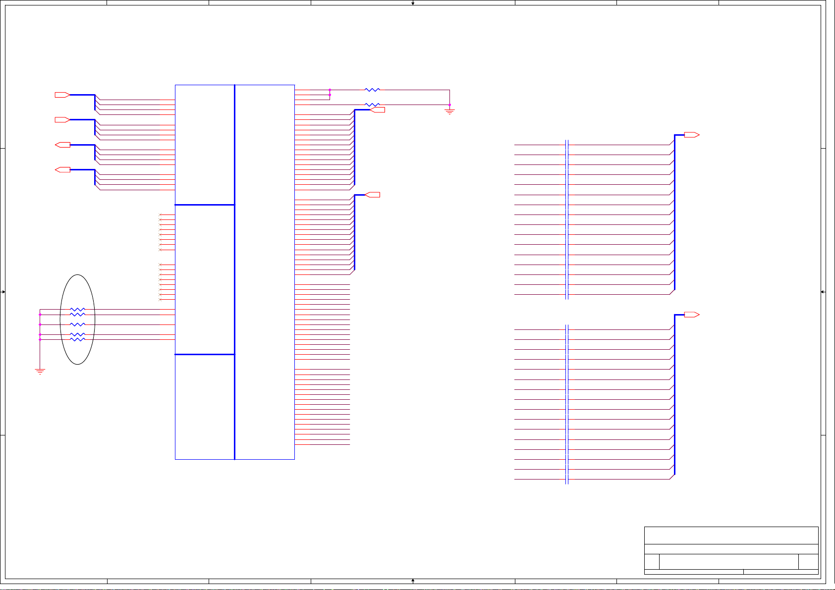
DMI_TXN[3:0]12
DMI_TXP[3:0]12
DMI_RXN[3:0]12
DMI_RXP[3:0]12
B B
R1602 1K_J 0402R1602 1K_J 0402
1 2
R1600 1K_J 0402R1600 1K_J 0402
1 2
R1601 1K_J 0402R1601 1K_J 0402
1 2
R1614 1K_J 0402R1614 1K_J 0402
1 2
R1603 1K_J 0402R1603 1K_J 0402
1 2
C C
For Disable Arrandale Graphic
In addition, FDI_RXN_[7:0] and FDI_RXP_[7:0] can be left floating on the PCH.
FDI_TX[7:0] and FDI_TX#[7:0] can be left floating on the Arrandale. The
D D
GFX_IMON,FDI_FSYNC[0], FDI_FSYNC[1], FDI_LSYNC[0], FDI_LSYNC[1], and FDI_INT
signals on the Arrandale side should be tied to GND (through 1-kΩ ±5% resistors).
FDI_FSYNC[0], FDI_FSYNC[1], FDI_LSYNC[0], FDI_LSYNC[1] can be ganged together with
one resistor.
FDI_FSYNC[0], FDI_FSYNC[1],
FDI_LSYNC[0], FDI_LSYNC[1]
can be ganged together with
one resistor
1
DMI_TXN0
DMI_TXN1
DMI_TXN2
DMI_TXN3
DMI_TXP0
DMI_TXP1
DMI_TXP2
DMI_TXP3
DMI_RXN0
DMI_RXN1
DMI_RXN2
DMI_RXN3
DMI_RXP0
DMI_RXP1
DMI_RXP2
DMI_RXP3
FDI_FSYNC0
FDI_FSYNC1
FDI_INT
FDI_LSYNC0
FDI_LSYNC1
U67A
U67A
A24
DMI_RX#[0]
C23
DMI_RX#[1]
B22
DMI_RX#[2]
A21
DMI_RX#[3]
B24
DMI_RX[0]
D23
DMI_RX[1]
B23
DMI_RX[2]
A22
DMI_RX[3]
D24
DMI_TX#[0]
G24
DMI_TX#[1]
F23
DMI_TX#[2]
H23
DMI_TX#[3]
D25
DMI_TX[0]
F24
DMI_TX[1]
E23
DMI_TX[2]
G23
DMI_TX[3]
E22
FDI_TX#[0]
D21
FDI_TX#[1]
D19
FDI_TX#[2]
D18
FDI_TX#[3]
G21
FDI_TX#[4]
E19
FDI_TX#[5]
F21
FDI_TX#[6]
G18
FDI_TX#[7]
D22
FDI_TX[0]
C21
FDI_TX[1]
D20
FDI_TX[2]
C18
FDI_TX[3]
G22
FDI_TX[4]
E20
FDI_TX[5]
F20
FDI_TX[6]
G19
FDI_TX[7]
F17
FDI_FSYNC[0]
E17
FDI_FSYNC[1]
C17
FDI_INT
F18
FDI_LSYNC[0]
D17
FDI_LSYNC[1]
CPU SOCKET_989P
CPU SOCKET_989P
FOX_PZ98927-3641-01F
FOX_PZ98927-3641-01F
2
PEG_COMP
PEG_RX[0]
PEG_RX[1]
PEG_RX[2]
PEG_RX[3]
PEG_RX[4]
PEG_RX[5]
PEG_RX[6]
PEG_RX[7]
PEG_RX[8]
PEG_RX[9]
PEG_TX[0]
PEG_TX[1]
PEG_TX[2]
PEG_TX[3]
PEG_TX[4]
PEG_TX[5]
PEG_TX[6]
PEG_TX[7]
PEG_TX[8]
PEG_TX[9]
B26
A26
B27
A25
K35
J34
J33
G35
G32
F34
F31
D35
E33
C33
D32
B32
C31
B28
B30
A31
J35
H34
H33
F35
G33
E34
F32
D34
F33
B33
D31
A32
C30
A28
B29
A30
L33
M35
M33
M30
L31
K32
M29
J31
K29
H30
H29
F29
E28
D29
D27
C26
L34
M34
M32
L30
M31
K31
M28
H31
K28
G30
G29
F28
E27
D28
C27
C25
PEG_RBIAS
PEG_RXN15
PEG_RXN14
PEG_RXN13
PEG_RXN12
PEG_RXN11
PEG_RXN10
PEG_RXN9
PEG_RXN8
PEG_RXN7
PEG_RXN6
PEG_RXN5
PEG_RXN4
PEG_RXN3
PEG_RXN2
PEG_RXN1
PEG_RXN0
PEG_RXP15
PEG_RXP14
PEG_RXP13
PEG_RXP12
PEG_RXP11
PEG_RXP10
PEG_RXP9
PEG_RXP8
PEG_RXP7
PEG_RXP6
PEG_RXP5
PEG_RXP4
PEG_RXP3
PEG_RXP2
PEG_RXP1
PEG_RXP0
PEG_TXN15
PEG_TXN14
PEG_TXN13
PEG_TXN12
PEG_TXN11
PEG_TXN10
PEG_TXN9
PEG_TXN8
PEG_TXN7
PEG_TXN6
PEG_TXN5
PEG_TXN4
PEG_TXN3
PEG_TXN2
PEG_TXN1
PEG_TXN0
PEG_TXP15
PEG_TXP14
PEG_TXP13
PEG_TXP12
PEG_TXP11
PEG_TXP10
PEG_TXP9
PEG_TXP8
PEG_TXP7
PEG_TXP6
PEG_TXP5
PEG_TXP4
PEG_TXP3
PEG_TXP2
PEG_TXP1
PEG_TXP0
PEG_ICOMPI
PEG_ICOMPO
PEG_RCOMPO
PEG_RBIAS
PEG_RX#[0]
PEG_RX#[1]
DMI Intel(R) FDI
DMI Intel(R) FDI
PEG_RX#[2]
PEG_RX#[3]
PEG_RX#[4]
PEG_RX#[5]
PEG_RX#[6]
PEG_RX#[7]
PEG_RX#[8]
PEG_RX#[9]
PEG_RX#[10]
PEG_RX#[11]
PEG_RX#[12]
PEG_RX#[13]
PEG_RX#[14]
PEG_RX#[15]
PEG_RX[10]
PEG_RX[11]
PEG_RX[12]
PEG_RX[13]
PEG_RX[14]
PEG_RX[15]
PEG_TX#[0]
PEG_TX#[1]
PEG_TX#[2]
PEG_TX#[3]
PEG_TX#[4]
PEG_TX#[5]
PEG_TX#[6]
PEG_TX#[7]
PEG_TX#[8]
PEG_TX#[9]
PEG_TX#[10]
PEG_TX#[11]
PEG_TX#[12]
PEG_TX#[13]
PEG_TX#[14]
PEG_TX#[15]
PCI EXPRESS -- GRAPHICS
PCI EXPRESS -- GRAPHICS
PEG_TX[10]
PEG_TX[11]
PEG_TX[12]
PEG_TX[13]
PEG_TX[14]
PEG_TX[15]
3
R361 49.9_F 0402R361 49.9_F 0402
1 2
R848 750_F 0402R848 750_F 0402
1 2
PEG_RXN[15..0] 22
PEG_RXP[15..0] 22
4
If PCIe Graphics is not implemented,
the TX/RX pairs can be left as No Connect.
PEG_TXN0
PEG_TXN1
PEG_TXN2
PEG_TXN3
PEG_TXN4
PEG_TXN5
PEG_TXN6
PEG_TXN7
PEG_TXN8
PEG_TXN9
PEG_TXN10
PEG_TXN11
PEG_TXN12
PEG_TXN13
PEG_TXN14
PEG_TXN15
PEG_TXP0
PEG_TXP1
PEG_TXP2
PEG_TXP3
PEG_TXP4
PEG_TXP5
PEG_TXP6
PEG_TXP7
PEG_TXP8
PEG_TXP9 PEG_RXP_C9
PEG_TXP10
PEG_TXP11
PEG_TXP12
PEG_TXP13
PEG_TXP14
PEG_TXP15
5
1 2
C589 0.1U_6.3V_K 0402_X5RC589 0.1U_6.3V_K 0402_X5R
1 2
C591 0.1U_6.3V_K 0402_X5RC591 0.1U_6.3V_K 0402_X5R
1 2
C594 0.1U_6.3V_K 0402_X5RC594 0.1U_6.3V_K 0402_X5R
1 2
C595 0.1U_6.3V_K 0402_X5RC595 0.1U_6.3V_K 0402_X5R
1 2
C597 0.1U_6.3V_K 0402_X5RC597 0.1U_6.3V_K 0402_X5R
1 2
C600 0.1U_6.3V_K 0402_X5RC600 0.1U_6.3V_K 0402_X5R
1 2
C603 0.1U_6.3V_K 0402_X5RC603 0.1U_6.3V_K 0402_X5R
1 2
C604 0.1U_6.3V_K 0402_X5RC604 0.1U_6.3V_K 0402_X5R
1 2
C607 0.1U_6.3V_K 0402_X5RC607 0.1U_6.3V_K 0402_X5R
1 2
C611 0.1U_6.3V_K 0402_X5RC611 0.1U_6.3V_K 0402_X5R
1 2
C615 0.1U_6.3V_K 0402_X5RC615 0.1U_6.3V_K 0402_X5R
1 2
C617 0.1U_6.3V_K 0402_X5RC617 0.1U_6.3V_K 0402_X5R
1 2
C659 0.1U_6.3V_K 0402_X5RC659 0.1U_6.3V_K 0402_X5R
1 2
C627 0.1U_6.3V_K 0402_X5RC627 0.1U_6.3V_K 0402_X5R
1 2
C631 0.1U_6.3V_K 0402_X5RC631 0.1U_6.3V_K 0402_X5R
1 2
C641 0.1U_6.3V_K 0402_X5RC641 0.1U_6.3V_K 0402_X5R
1 2
C588 0.1U_6.3V_K 0402_X5RC588 0.1U_6.3V_K 0402_X5R
1 2
C590 0.1U_6.3V_K 0402_X5RC590 0.1U_6.3V_K 0402_X5R
1 2
C592 0.1U_6.3V_K 0402_X5RC592 0.1U_6.3V_K 0402_X5R
1 2
C593 0.1U_6.3V_K 0402_X5RC593 0.1U_6.3V_K 0402_X5R
1 2
C596 0.1U_6.3V_K 0402_X5RC596 0.1U_6.3V_K 0402_X5R
1 2
C598 0.1U_6.3V_K 0402_X5RC598 0.1U_6.3V_K 0402_X5R
1 2
C601 0.1U_6.3V_K 0402_X5RC601 0.1U_6.3V_K 0402_X5R
1 2
C602 0.1U_6.3V_K 0402_X5RC602 0.1U_6.3V_K 0402_X5R
1 2
C605 0.1U_6.3V_K 0402_X5RC605 0.1U_6.3V_K 0402_X5R
1 2
C608 0.1U_6.3V_K 0402_X5RC608 0.1U_6.3V_K 0402_X5R
1 2
C612 0.1U_6.3V_K 0402_X5RC612 0.1U_6.3V_K 0402_X5R
1 2
C616 0.1U_6.3V_K 0402_X5RC616 0.1U_6.3V_K 0402_X5R
1 2
C61 0.1U_6.3V_K 0402_X5RC61 0.1U_6.3V_K 0402_X5R
1 2
C65 0.1U_6.3V_K 0402_X5RC65 0.1U_6.3V_K 0402_X5R
1 2
C628 0.1U_6.3V_K 0402_X5RC628 0.1U_6.3V_K 0402_X5R
1 2
C642 0.1U_6.3V_K 0402_X5RC642 0.1U_6.3V_K 0402_X5R
6
PEG_RXN_C0
PEG_RXN_C1
PEG_RXN_C2
PEG_RXN_C3
PEG_RXN_C4
PEG_RXN_C5
PEG_RXN_C6
PEG_RXN_C7
PEG_RXN_C8
PEG_RXN_C9
PEG_RXN_C10
PEG_RXN_C11
PEG_RXN_C12
PEG_RXN_C13
PEG_RXN_C14
PEG_RXN_C15
PEG_RXP_C0
PEG_RXP_C1
PEG_RXP_C2
PEG_RXP_C3
PEG_RXP_C4
PEG_RXP_C5
PEG_RXP_C6
PEG_RXP_C7
PEG_RXP_C8
PEG_RXP_C10
PEG_RXP_C11
PEG_RXP_C12
PEG_RXP_C13
PEG_RXP_C14
PEG_RXP_C15
FOXCONN
FOXCONN
FOXCONN
Title
Title
Title
ARD (DMI,PEG,FDI)
ARD (DMI,PEG,FDI)
ARD (DMI,PEG,FDI)
Size Document Number Rev
Size Document Number Rev
Size Document Number Rev
A3
A3
A3
M960&M970 H Model SA
M960&M970 H Model SA
M960&M970 H Model SA
Date: Sheet
Date: Sheet
Date: Sheet
7
PEG_RXN_C[15..0] 22
PEG_RXP_C[15..0] 22
HON HAI Precision Ind. Co., Ltd.
HON HAI Precision Ind. Co., Ltd.
HON HAI Precision Ind. Co., Ltd.
CCPBG - R&D Division
CCPBG - R&D Division
CCPBG - R&D Division
386Tuesday, December 29, 2009
386Tuesday, December 29, 2009
386Tuesday, December 29, 2009
of
of
of
8
Page 4
5
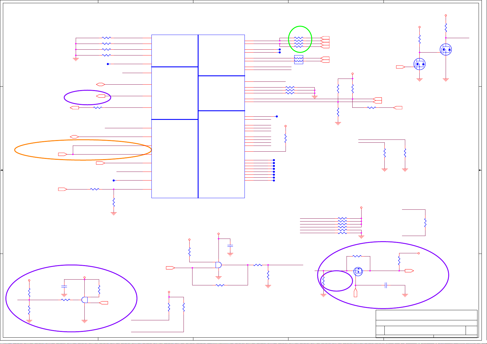
Layout Note:
Comp0,1 connect with Zo=49.9 ohm,
Comp2,3 connect with Zo=20 ohm,
In order to minimize resistance,
use thick traces to route all
COMP signals, use 10-mils
(0.254-mm) wide trace for
routing less than 500 mils (12.7
mm), or 20-mils (0.508-mm)
wide trace for routing between
500 mils (12.7 mm) and
1000 mils (25.4 mm). Keep 20-mils
D D
(0.508-mm) spacing to
any other signals in order to
minimize crosstalk.
DVT
PM_THRMTRIP#15,39
C C
H_PM_SYNC12
R849 20_F 0402R849 20_F 0402
1 2
R850 20_F 0402R850 20_F 0402
1 2
R851 49.9_F 0402R851 49.9_F 0402
1 2
R852 49.9_F 0402R852 49.9_F 0402
1 2
TP6020MIL TP6020MIL
H_PECI15
PROCHOT#78
R939 0_J 0402R939 0_J 0402
1 2
MP
H_CPUPWRGD15
PM_DRAM_PWRGD12
TP9420MIL TP9420MIL
R925
R925
BUF_PLT_RST#14,39,42,43
B B
1 2
1.5K_F 0402
1.5K_F 0402
COMP3
COMP2
COMP1
COMP0
SKTOCC#
1
H_CATERR#
H_PECI
PROCHOT#
PM_THRMTRIP#_1
H_CPURST#_R
H_PM_SYNC
H_CPUPWRGD
H_CPUPWRGD
PM_DRAM_PWRGD
VTTPWRGOOD
TAPPWRGOOD
1
BUF_PLT_RST#_R
12
R926
R926
750_F
750_F
0402
0402
For Intel S3 Power Reduction issue
+1_5VRUN
12
R5950
R5950
NC_1.1K_F
NC_1.1K_F
0402
A A
0402
PM_DRAM_PWRGDPM_DRAM_PWRGD
12
0402
0402
750_F
750_F
R5927
R5927
74AHC1G08GW
74AHC1G08GW
12
C6316
C6316
0.1U_6.3V_K
0.1U_6.3V_K
0402_X5R
0402_X5R
R5926
R5926
1.5K_F0402
1.5K_F0402
+3VALW
12
R5951
R5951
10K_J
10K_J
0402
0402
U217
U217
53
1
4
12
2
RUN_PWRGD 12,39,75,76,80
DVT
5
4
U67B
U67B
AT23
AT24
G16
AT26
AH24
AK14
AT15
AN26
AK15
AP26
AL15
AN14
AN27
AK13
AM15
AM26
AL14
CPU SOCKET_989P
CPU SOCKET_989P
FOX_PZ98927-3641-01F
FOX_PZ98927-3641-01F
RUN_PWRGD12,39,75,76,80
H_CATERR#
H_CPURST#_R
4
COMP3
COMP2
COMP1
COMP0
SKTOCC#
CATERR#
PECI
PROCHOT#
THERMTRIP#
RESET_OBS#
PM_SYNC
VCCPWRGOOD_1
VCCPWRGOOD_0
SM_DRAMPWROK
VTTPWRGOOD
TAPPWRGOOD
RSTIN#
+1_05V_VTT
1 2
R861
R861
49.9_F
49.9_F
0402
0402
MISC THERMAL
MISC THERMAL
BCLK_ITP#
PEG_CLK#
DPLL_REF_SSCLK
DPLL_REF_SSCLK#
CLOCKS
CLOCKS
SM_DRAMRST#
SM_RCOMP[0]
SM_RCOMP[1]
SM_RCOMP[2]
PM_EXT_TS#[0]
PM_EXT_TS#[1]
DDR3
MISC
DDR3
MISC
PWR MANAGEMENT
PWR MANAGEMENT
JTAG & BPM
JTAG & BPM
+3VRUN
+3VRUN
12
R14
R14
10K_J
10K_J
0402
12
R936
R936
NC_68_J
NC_68_J
0402
0402
0402
RUN_PWRGD
U2
U2
53
1
VTTPW_R
4
2
74AHC1G08GW
74AHC1G08GW
R970 NC_0_J 0402R970 NC_0_J 0402
1 2
3
A16
BCLK
B16
BCLK#
AR30
BCLK_ITP
AT30
E16
PEG_CLK
D16
A18
A17
F6
AL1
AM1
AN1
AN15
AP15
AT28
PRDY#
AP27
PREQ#
AN28
TCK
AP28
TMS
AT27
TRST#
AT29
TDI
AR27
TDO
AR29
TDI_M
AP29
TDO_M
AN25
DBR#
AJ22
BPM#[0]
AK22
BPM#[1]
AK24
BPM#[2]
AJ24
BPM#[3]
AJ25
BPM#[4]
AH22
BPM#[5]
AK23
BPM#[6]
AH23
BPM#[7]
12
C13
C13
0.1U_6.3V_K
0.1U_6.3V_K
0402_X5R
0402_X5R
R1572 2K_F 0402R1572 2K_F 0402
1 2
3
ARD_BCLK
ARD_BCLK#
BCLK_ITP
1
BCLK_ITP#
1
CLK_EXP_P_R
CLK_EXP_N_R
CLK_DP_P_R
CLK_DP_N_R
DDR3_DRAMRST#_Q
SM_RCOMP0
R854 100_F 0402R854 100_F 0402
SM_RCOMP1
R853 24.9_F 0402R853 24.9_F 0402
SM_RCOMP2
R855 130_F 0402R855 130_F 0402
XDP_PRDY#
1
XDP_PREQ#
XDP_TCLK
XDP_TMS
XDP_TRST#
XDP_TDI_R
XDP_TDO_R
XDP_TDI_M
XDP_TDO_M
XDP_DBRESET#
BPM#0
1
BPM#1
1
BPM#2
1
BPM#3
1
BPM#4
1
BPM#5
1
BPM#6
1
BPM#7
1
12
R1573
R1573
1K_F
1K_F
0402
0402
R1450 0_J 0402R1450 0_J 0402
1 2
R1451 NC_0_J 0402R1451 NC_0_J 0402
1 2
R1452 NC_0_J 0402R1452 NC_0_J 0402
1 2
R1453 0_J 0402R1453 0_J 0402
1 2
20MIL
20MIL
TP61
TP61
20MIL
20MIL
TP63
TP63
1
2 3
RP80
1 2
1 2
1 2
PM_EXTTS#0
PM_EXTTS#1
20MIL
20MIL
TP75
TP75
+3VRUN
R1292
R1292
NC_51_J
NC_51_J
0402
0402
1 2
20MIL
20MIL
TP64
TP64
20MIL
20MIL
TP65
TP65
20MIL
20MIL
TP66
TP66
20MIL
20MIL
TP67
TP67
20MIL
20MIL
TP68
TP68
20MIL
20MIL
TP69
TP69
20MIL
20MIL
TP70
TP70
20MIL
20MIL
TP71
TP71
VTTPWRGOOD
0
0
4
0404_4P2RRP80
0404_4P2R
XDP_TDO_R
XDP_TMS
XDP_TDI_R
XDP_PREQ#
XDP_TCLK
XDP_TRST#
2
CLK_PCH_CPU_CLK 15
CLK_CPU_BCLK 19
CLK_CPU_BCLK# 19
EVT
CLK_PCH_CPU_CLK# 15
CLK_EXP_P 11
CLK_EXP_N 11
OVT_EC#39
+1_05V_VTT
12
12
R932
R932
R933
R933
10K_J
10K_J
10K_J
10K_J
0402
0402
0402
0402
12
For Disable Arrandale Graphic
DPLL_REF_SSCLK and DPLL_REF_SSCLK# can be connected to GND on
Arrandale directly if motherboard only supports discrete graphics.
R129051_J 0402R129051_J 0402
1 2
R1258NC_51_J 0402R1258NC_51_J 0402
1 2
R1259NC_51_J 0402R1259NC_51_J 0402
1 2
R1260NC_51_J 0402R1260NC_51_J 0402
1 2
R1261NC_51_J 0402R1261NC_51_J 0402
1 2
R126251_J 0402R126251_J 0402
R1231
R1231
NC_12.4K_F
NC_12.4K_F
0402
0402
12
R962 0_J 0402R962 0_J 0402
1 2
CLK_DP_P_R
CLK_DP_N_R
+1_05V_VTT
PM_EXTTS#0 20
PM_EXTTS#1 20,21
12
R1607
R1607
0_J
0_J
0402
0402
JTAG Mapping -Scan Chain (Default)
For Intel S3 Power Reduction issue
R5948 NC_0_J 0402R5948 NC_0_J 0402
1 2
Q72
Q72
2N7002W
2N7002W
null
null
S
S
D
D
DDR3_DRAMRST#_Q
12
R5949
R5949
100K_J
100K_J
0402
0402
2
DVT
G
G
1
RST_GATE15
DDR3_DRAMRST#
32
C6317
C6317
1 2
0.047U_16V_K
0.047U_16V_K
0402_X7R
0402_X7R
FOXCONN
FOXCONN
FOXCONN
Title
Title
Title
ARD (CLK,MISC,JTAG)
ARD (CLK,MISC,JTAG)
ARD (CLK,MISC,JTAG)
Size Document Number Rev
Size Document Number Rev
Size Document Number Rev
A3
A3
A3
M960&M970 H Model SA
M960&M970 H Model SA
M960&M970 H Model SA
Date: Sheet
Date: Sheet
Date: Sheet
DDR_ALERT# 58
12
R1608
R1608
0_J
0_J
0402
0402
XDP_TDO_M
XDP_TDI_M
12
0402
0402
1K_J
1K_J
R5925
R5925
2
1
+1_05V_VTT
+3VRUN
12
R262
R262
4.7K_J
4.7K_J
0402
0402
61
Q14B
Q14B
D
D
G
G
S
S
+1_5VSUS
DDR3_DRAMRST# 20,21
A0205
2N7002DW
2N7002DW
null
null
1 2
R969
R969
0_J
0_J
0402
0402
G
G
5
DVT
HON HAI Precision Ind. Co., Ltd.
HON HAI Precision Ind. Co., Ltd.
HON HAI Precision Ind. Co., Ltd.
CCPBG - R&D Division
CCPBG - R&D Division
CCPBG - R&D Division
1
12
R258
R258
68_J
68_J
0402
0402
34
Q14A
Q14A
D
D
S
S
486Tuesday, December 29, 2009
486Tuesday, December 29, 2009
486Tuesday, December 29, 2009
PROCHOT#
2N7002DW
2N7002DW
null
null
of
of
of
Page 5

5
U67C
U67C
4
3
U67D
U67D
2
1
AA6
SA_CK[0]
AA7
SA_CK#[0]
D D
C C
B B
M_A_DQ[63:0]20
M_A_BS020
M_A_BS120
M_A_BS220
M_A_CAS#20
M_A_RAS#20
M_A_WE#20
M_A_DQ0
M_A_DQ1
M_A_DQ2
M_A_DQ3
M_A_DQ4
M_A_DQ5
M_A_DQ6
M_A_DQ7
M_A_DQ8
M_A_DQ9
M_A_DQ10
M_A_DQ11
M_A_DQ12
M_A_DQ13
M_A_DQ14
M_A_DQ15
M_A_DQ16
M_A_DQ17
M_A_DQ18
M_A_DQ19
M_A_DQ20
M_A_DQ21
M_A_DQ22
M_A_DQ23
M_A_DQ24
M_A_DQ25
M_A_DQ26
M_A_DQ27
M_A_DQ28
M_A_DQ29
M_A_DQ30
M_A_DQ31
M_A_DQ32
M_A_DQ33
M_A_DQ34
M_A_DQ35
M_A_DQ36
M_A_DQ37
M_A_DQ38
M_A_DQ39
M_A_DQ40
M_A_DQ41
M_A_DQ42
M_A_DQ43
M_A_DQ44
M_A_DQ45
M_A_DQ46
M_A_DQ47
M_A_DQ48
M_A_DQ49
M_A_DQ50
M_A_DQ51
M_A_DQ52
M_A_DQ53
M_A_DQ54
M_A_DQ55
M_A_DQ56
M_A_DQ57
M_A_DQ58
M_A_DQ59
M_A_DQ60
M_A_DQ61
M_A_DQ62
M_A_DQ63
C10
D10
H10
G10
AH5
AF5
AK6
AK7
AF6
AG5
AJ10
AL10
AK12
AK8
AK11
AN8
AM10
AR11
AL11
AM9
AN9
AT11
AP12
AM12
AN12
AM13
AT14
AT12
AL13
AR14
AP14
AC3
AB2
AE1
AB3
AE9
A10
B10
E10
F10
J10
AJ7
AJ6
AJ9
AL7
AL8
G8
G7
M6
M8
C7
A7
A8
D8
E6
F7
E9
B7
E7
C6
K7
J8
J7
L7
L9
L6
K8
N8
P9
U7
SA_DQ[0]
SA_DQ[1]
SA_DQ[2]
SA_DQ[3]
SA_DQ[4]
SA_DQ[5]
SA_DQ[6]
SA_DQ[7]
SA_DQ[8]
SA_DQ[9]
SA_DQ[10]
SA_DQ[11]
SA_DQ[12]
SA_DQ[13]
SA_DQ[14]
SA_DQ[15]
SA_DQ[16]
SA_DQ[17]
SA_DQ[18]
SA_DQ[19]
SA_DQ[20]
SA_DQ[21]
SA_DQ[22]
SA_DQ[23]
SA_DQ[24]
SA_DQ[25]
SA_DQ[26]
SA_DQ[27]
SA_DQ[28]
SA_DQ[29]
SA_DQ[30]
SA_DQ[31]
SA_DQ[32]
SA_DQ[33]
SA_DQ[34]
SA_DQ[35]
SA_DQ[36]
SA_DQ[37]
SA_DQ[38]
SA_DQ[39]
SA_DQ[40]
SA_DQ[41]
SA_DQ[42]
SA_DQ[43]
SA_DQ[44]
SA_DQ[45]
SA_DQ[46]
SA_DQ[47]
SA_DQ[48]
SA_DQ[49]
SA_DQ[50]
SA_DQ[51]
SA_DQ[52]
SA_DQ[53]
SA_DQ[54]
SA_DQ[55]
SA_DQ[56]
SA_DQ[57]
SA_DQ[58]
SA_DQ[59]
SA_DQ[60]
SA_DQ[61]
SA_DQ[62]
SA_DQ[63]
SA_BS[0]
SA_BS[1]
SA_BS[2]
SA_CAS#
SA_RAS#
SA_WE#
SA_DQS#[0]
SA_DQS#[1]
SA_DQS#[2]
SA_DQS#[3]
SA_DQS#[4]
SA_DQS#[5]
SA_DQS#[6]
SA_DQS#[7]
DDR SYSTEM MEMORY A
DDR SYSTEM MEMORY A
SA_CKE[0]
SA_CK[1]
SA_CK#[1]
SA_CKE[1]
SA_CS#[0]
SA_CS#[1]
SA_ODT[0]
SA_ODT[1]
SA_DM[0]
SA_DM[1]
SA_DM[2]
SA_DM[3]
SA_DM[4]
SA_DM[5]
SA_DM[6]
SA_DM[7]
SA_DQS[0]
SA_DQS[1]
SA_DQS[2]
SA_DQS[3]
SA_DQS[4]
SA_DQS[5]
SA_DQS[6]
SA_DQS[7]
SA_MA[0]
SA_MA[1]
SA_MA[2]
SA_MA[3]
SA_MA[4]
SA_MA[5]
SA_MA[6]
SA_MA[7]
SA_MA[8]
SA_MA[9]
SA_MA[10]
SA_MA[11]
SA_MA[12]
SA_MA[13]
SA_MA[14]
SA_MA[15]
P7
Y6
Y5
P6
AE2
AE8
AD8
AF9
B9
D7
H7
M7
AG6
AM7
AN10
AN13
C9
F8
J9
N9
AH7
AK9
AP11
AT13
C8
F9
H9
M9
AH8
AK10
AN11
AR13
Y3
W1
AA8
AA3
V1
AA9
V8
T1
Y9
U6
AD4
T2
U3
AG8
T3
V9
M_A_DQS#0
M_A_DQS#1
M_A_DQS#2
M_A_DQS#3
M_A_DQS#4
M_A_DQS#5
M_A_DQS#6
M_A_DQS#7
M_A_A0
M_A_A1
M_A_A2
M_A_A3
M_A_A4
M_A_A5
M_A_A6
M_A_A7
M_A_A8
M_A_A9
M_A_A10
M_A_A11
M_A_A12
M_A_A13
M_A_A14
M_A_A15
M_A_DM0
M_A_DM1
M_A_DM2
M_A_DM3
M_A_DM4
M_A_DM5
M_A_DM6
M_A_DM7
M_A_DQS0
M_A_DQS1
M_A_DQS2
M_A_DQS3
M_A_DQS4
M_A_DQS5
M_A_DQS6
M_A_DQS7
M_CLK_DDR0 20
M_CLK_DDR#0 20
M_CKE0 20
M_CLK_DDR1 20
M_CLK_DDR#1 20
M_CKE1 20
M_CS#0 20
M_CS#1 20
M_ODT0 20
M_ODT1 20
M_B_DQ[63:0]21
M_A_DM[7:0] 20
M_A_DQS#[7:0] 20
M_A_DQS[7:0] 20
M_A_A[15:0] 20
M_B_DQ0
M_B_DQ1
M_B_DQ2
M_B_DQ3
M_B_DQ4
M_B_DQ5
M_B_DQ6
M_B_DQ7
M_B_DQ8
M_B_DQ9
M_B_DQ10
M_B_DQ11
M_B_DQ12
M_B_DQ13
M_B_DQ14
M_B_DQ15
M_B_DQ16
M_B_DQ17
M_B_DQ18
M_B_DQ19
M_B_DQ20
M_B_DQ21
M_B_DQ22
M_B_DQ23
M_B_DQ24
M_B_DQ25
M_B_DQ26
M_B_DQ27
M_B_DQ28
M_B_DQ29
M_B_DQ30
M_B_DQ31
M_B_DQ32
M_B_DQ33
M_B_DQ34
M_B_DQ35
M_B_DQ36
M_B_DQ37
M_B_DQ38
M_B_DQ39
M_B_DQ40
M_B_DQ41
M_B_DQ42
M_B_DQ43
M_B_DQ44
M_B_DQ45
M_B_DQ46
M_B_DQ47
M_B_DQ48
M_B_DQ49
M_B_DQ50
M_B_DQ51
M_B_DQ52
M_B_DQ53
M_B_DQ54
M_B_DQ55
M_B_DQ56
M_B_DQ57
M_B_DQ58
M_B_DQ59
M_B_DQ60
M_B_DQ61
M_B_DQ62
M_B_DQ63
M_B_BS021
M_B_BS121
M_B_BS221
M_B_CAS#21
M_B_RAS#21
M_B_WE#21
AF3
AG1
AK1
AG4
AG3
AH4
AK3
AK4
AM6
AN2
AK5
AK2
AM4
AM3
AP3
AN5
AT4
AN6
AN4
AN3
AT5
AT6
AN7
AP6
AP8
AT9
AT7
AP9
AR10
AT10
AB1
AC5
AC6
AJ3
AJ4
B5
A5
C3
B3
E4
A6
A4
C4
D1
D2
F2
F1
C2
F5
F3
G4
H6
G2
J6
J3
G1
G5
J2
J1
J5
K2
L3
M1
K5
K4
M4
N5
W5
R7
Y7
SB_DQ[0]
SB_DQ[1]
SB_DQ[2]
SB_DQ[3]
SB_DQ[4]
SB_DQ[5]
SB_DQ[6]
SB_DQ[7]
SB_DQ[8]
SB_DQ[9]
SB_DQ[10]
SB_DQ[11]
SB_DQ[12]
SB_DQ[13]
SB_DQ[14]
SB_DQ[15]
SB_DQ[16]
SB_DQ[17]
SB_DQ[18]
SB_DQ[19]
SB_DQ[20]
SB_DQ[21]
SB_DQ[22]
SB_DQ[23]
SB_DQ[24]
SB_DQ[25]
SB_DQ[26]
SB_DQ[27]
SB_DQ[28]
SB_DQ[29]
SB_DQ[30]
SB_DQ[31]
SB_DQ[32]
SB_DQ[33]
SB_DQ[34]
SB_DQ[35]
SB_DQ[36]
SB_DQ[37]
SB_DQ[38]
SB_DQ[39]
SB_DQ[40]
SB_DQ[41]
SB_DQ[42]
SB_DQ[43]
SB_DQ[44]
SB_DQ[45]
SB_DQ[46]
SB_DQ[47]
SB_DQ[48]
SB_DQ[49]
SB_DQ[50]
SB_DQ[51]
SB_DQ[52]
SB_DQ[53]
SB_DQ[54]
SB_DQ[55]
SB_DQ[56]
SB_DQ[57]
SB_DQ[58]
SB_DQ[59]
SB_DQ[60]
SB_DQ[61]
SB_DQ[62]
SB_DQ[63]
SB_BS[0]
SB_BS[1]
SB_BS[2]
SB_CAS#
SB_RAS#
SB_WE#
SB_DQS#[0]
SB_DQS#[1]
SB_DQS#[2]
SB_DQS#[3]
SB_DQS#[4]
SB_DQS#[5]
SB_DQS#[6]
SB_DQS#[7]
DDR SYSTEM MEMORY - B
DDR SYSTEM MEMORY - B
SB_CK[0]
SB_CK#[0]
SB_CKE[0]
SB_CK[1]
SB_CK#[1]
SB_CKE[1]
SB_CS#[0]
SB_CS#[1]
SB_ODT[0]
SB_ODT[1]
SB_DM[0]
SB_DM[1]
SB_DM[2]
SB_DM[3]
SB_DM[4]
SB_DM[5]
SB_DM[6]
SB_DM[7]
SB_DQS[0]
SB_DQS[1]
SB_DQS[2]
SB_DQS[3]
SB_DQS[4]
SB_DQS[5]
SB_DQS[6]
SB_DQS[7]
SB_MA[0]
SB_MA[1]
SB_MA[2]
SB_MA[3]
SB_MA[4]
SB_MA[5]
SB_MA[6]
SB_MA[7]
SB_MA[8]
SB_MA[9]
SB_MA[10]
SB_MA[11]
SB_MA[12]
SB_MA[13]
SB_MA[14]
SB_MA[15]
W8
W9
M3
V7
V6
M2
AB8
AD6
AC7
AD1
D4
E1
H3
K1
AH1
AL2
AR4
AT8
D5
F4
J4
L4
AH2
AL4
AR5
AR8
C5
E3
H4
M5
AG2
AL5
AP5
AR7
U5
V2
T5
V3
R1
T8
R2
R6
R4
R5
AB5
P3
R3
AF7
P5
N1
M_B_DM0
M_B_DM1
M_B_DM2
M_B_DM3
M_B_DM4
M_B_DM5
M_B_DM6
M_B_DM7
M_B_DQS#0
M_B_DQS#1
M_B_DQS#2
M_B_DQS#3
M_B_DQS#4
M_B_DQS#5
M_B_DQS#6
M_B_DQS#7
M_B_DQS0
M_B_DQS1
M_B_DQS2
M_B_DQS3
M_B_DQS4
M_B_DQS5
M_B_DQS6
M_B_DQS7
M_B_A0
M_B_A1
M_B_A2
M_B_A3
M_B_A4
M_B_A5
M_B_A6
M_B_A7
M_B_A8
M_B_A9
M_B_A10
M_B_A11
M_B_A12
M_B_A13
M_B_A14
M_B_A15
M_CLK_DDR2 21
M_CLK_DDR#2 21
M_CKE2 21
M_CLK_DDR3 21
M_CLK_DDR#3 21
M_CKE3 21
M_CS#2 21
M_CS#3 21
M_ODT2 21
M_ODT3 21
M_B_A[15:0] 21
M_B_DM[7:0] 21
M_B_DQS#[7:0] 21
M_B_DQS[7:0] 21
CPU SOCKET_989P
A A
5
CPU SOCKET_989P
FOX_PZ98927-3641-01F
FOX_PZ98927-3641-01F
CPU SOCKET_989P
CPU SOCKET_989P
FOX_PZ98927-3641-01F
FOX_PZ98927-3641-01F
HON HAI Precision Ind. Co., Ltd.
HON HAI Precision Ind. Co., Ltd.
FOXCONN
FOXCONN
FOXCONN
Title
Title
Title
ARD (DDR3)
ARD (DDR3)
ARD (DDR3)
Size Document Number Rev
Size Document Number Rev
Size Document Number Rev
A3
A3
A3
M960&M970 H Model SA
M960&M970 H Model SA
M960&M970 H Model SA
Date: Sheet
Date: Sheet
4
3
2
Date: Sheet
HON HAI Precision Ind. Co., Ltd.
CCPBG - R&D Division
CCPBG - R&D Division
CCPBG - R&D Division
of
of
of
586Tuesday, December 29, 2009
586Tuesday, December 29, 2009
1
586Tuesday, December 29, 2009
Page 6

1
2
3
U67F
U67F
4
5
6
7
8
EVT
48A (SV) 18A (SV) (VTT)
VHCORE
12
C509
C509
22U_6.3V_M
A A
B B
C C
D D
22U_6.3V_M
0805_X5R
0805_X5R
12
C490
C490
22U_6.3V_M
22U_6.3V_M
0805_X5R
0805_X5R
12
C495
C495
22U_6.3V_M
22U_6.3V_M
0805_X5R
0805_X5R
12
C508
C508
NC_22U_6.3V_M
NC_22U_6.3V_M
0805_X5R
0805_X5R
12
C925
C925
10U_10V_M
10U_10V_M
0805_X5R
0805_X5R
12
C930
C930
10U_10V_M
10U_10V_M
0805_X5R
0805_X5R
12
C491
C491
22U_6.3V_M
22U_6.3V_M
0805_X5R
0805_X5R
12
C48
C48
22U_6.3V_M
22U_6.3V_M
0805_X5R
0805_X5R
12
C497
C497
22U_6.3V_M
22U_6.3V_M
0805_X5R
0805_X5R
12
C921
C921
10U_10V_M
10U_10V_M
0805_X5R
0805_X5R
12
C926
C926
10U_10V_M
10U_10V_M
0805_X5R
0805_X5R
12
C931
C931
10U_10V_M
10U_10V_M
0805_X5R
0805_X5R
12
C935
C935
10U_10V_M
10U_10V_M
0805_X5R
0805_X5R
12
C510
C510
22U_6.3V_M
22U_6.3V_M
0805_X5R
0805_X5R
VHCORE
12
C492
C492
22U_6.3V_M
22U_6.3V_M
0805_X5R
0805_X5R
VHCORE
12
C499
C499
NC_22U_6.3V_M
NC_22U_6.3V_M
0805_X5R
0805_X5R
VHCORE
12
C922
C922
10U_10V_M
10U_10V_M
0805_X5R
0805_X5R
VHCORE
12
C927
C927
10U_10V_M
10U_10V_M
0805_X5R
0805_X5R
VHCORE
12
C932
C932
10U_10V_M
10U_10V_M
0805_X5R
0805_X5R
VHCORE
12
C936
C936
10U_10V_M
10U_10V_M
0805_X5R
0805_X5R
12
C496
C496
22U_6.3V_M
22U_6.3V_M
0805_X5R
0805_X5R
12
C504
C504
22U_6.3V_M
22U_6.3V_M
0805_X5R
0805_X5R
12
C503
C503
22U_6.3V_M
22U_6.3V_M
0805_X5R
0805_X5R
12
C923
C923
10U_10V_M
10U_10V_M
0805_X5R
0805_X5R
12
C928
C928
10U_10V_M
10U_10V_M
0805_X5R
0805_X5R
12
C933
C933
10U_10V_M
10U_10V_M
0805_X5R
0805_X5R
12
C5244
C5244
22P_50V_J
22P_50V_J
0402_NPO
0402_NPO
12
C502
C502
NC_22U_6.3V_M
NC_22U_6.3V_M
0805_X5R
0805_X5R
12
C507
C507
22U_6.3V_M
22U_6.3V_M
0805_X5R
0805_X5R
12
C505
C505
NC_22U_6.3V_M
NC_22U_6.3V_M
0805_X5R
0805_X5R
12
C924
C924
10U_10V_M
10U_10V_M
0805_X5R
0805_X5R
12
C929
C929
10U_10V_M
10U_10V_M
0805_X5R
0805_X5R
12
C934
C934
10U_10V_M
10U_10V_M
0805_X5R
0805_X5R
For RF Noise
12
C5245
C5245
22P_50V_J
22P_50V_J
0402_NPO
0402_NPO
VHCORE +1_05V_VTT
AG35
AG34
AG33
AG32
AG31
AG30
AG29
AG28
AG27
AG26
AF35
AF34
AF33
AF32
AF31
AF30
AF29
AF28
AF27
AF26
AD35
AD34
AD33
AD32
AD31
AD30
AD29
AD28
AD27
AD26
AC35
AC34
AC33
AC32
AC31
AC30
AC29
AC28
AC27
AC26
AA35
AA34
AA33
AA32
AA31
AA30
AA29
AA28
AA27
AA26
VCC1
VCC2
VCC3
VCC4
VCC5
VCC6
VCC7
VCC8
VCC9
VCC10
VCC11
VCC12
VCC13
VCC14
VCC15
VCC16
VCC17
VCC18
VCC19
VCC20
VCC21
VCC22
VCC23
VCC24
VCC25
VCC26
VCC27
VCC28
VCC29
VCC30
VCC31
VCC32
VCC33
VCC34
VCC35
VCC36
VCC37
VCC38
VCC39
VCC40
VCC41
VCC42
VCC43
VCC44
VCC45
VCC46
VCC47
VCC48
VCC49
VCC50
Y35
VCC51
Y34
VCC52
Y33
VCC53
Y32
VCC54
Y31
VCC55
Y30
VCC56
Y29
VCC57
Y28
VCC58
Y27
VCC59
Y26
VCC60
V35
VCC61
V34
VCC62
V33
VCC63
V32
VCC64
V31
VCC65
V30
VCC66
V29
VCC67
V28
VCC68
V27
VCC69
V26
VCC70
U35
VCC71
U34
VCC72
U33
VCC73
U32
VCC74
U31
VCC75
U30
VCC76
U29
VCC77
U28
VCC78
U27
VCC79
U26
VCC80
R35
VCC81
R34
VCC82
R33
VCC83
R32
VCC84
R31
VCC85
R30
VCC86
R29
VCC87
R28
VCC88
R27
VCC89
R26
VCC90
P35
VCC91
P34
VCC92
P33
VCC93
P32
VCC94
P31
VCC95
P30
VCC96
P29
VCC97
P28
VCC98
P27
VCC99
P26
VCC100
1.1V RAIL POWER
1.1V RAIL POWER
CPU CORE SUPPLY
CPU CORE SUPPLY
POWER
POWER
PROC_DPRSLPVR
CPU VIDS
CPU VIDS
VTT_SELECT
VCC_SENSE
VSS_SENSE
VSS_SENSE_VTT
SENSE LINES
SENSE LINES
VTT0_1
VTT0_2
VTT0_3
VTT0_4
VTT0_5
VTT0_6
VTT0_7
VTT0_8
VTT0_9
VTT0_10
VTT0_11
VTT0_12
VTT0_13
VTT0_14
VTT0_15
VTT0_16
VTT0_17
VTT0_18
VTT0_19
VTT0_20
VTT0_21
VTT0_22
VTT0_23
VTT0_24
VTT0_25
VTT0_26
VTT0_27
VTT0_28
VTT0_29
VTT0_30
VTT0_31
VTT0_32
VTT0_33
VTT0_34
VTT0_35
VTT0_36
VTT0_37
VTT0_38
VTT0_39
VTT0_40
VTT0_41
VTT0_42
VTT0_43
VTT0_44
PSI#
VID[0]
VID[1]
VID[2]
VID[3]
VID[4]
VID[5]
VID[6]
ISENSE
VTT_SENSE
AH14
AH12
AH11
AH10
J14
J13
H14
H12
G14
G13
G12
G11
F14
F13
F12
F11
E14
E12
D14
D13
D12
D11
C14
C13
C12
C11
B14
B12
A14
A13
A12
A11
AF10
AE10
AC10
AB10
Y10
W10
U10
T10
J12
J11
J16
J15
AN33
AK35
AK33
AK34
AL35
AL33
AM33
AM35
AM34
G15
AN35
AJ34
AJ35
B15
A15
PM_DPRSLPVR
VTT_SELECT
VCCSENSE
VSSSENSE
VSS_SENSE_VTT
+1_05V_VTT_43
+1_05V_VTT_44
1
1
12
C911
C911
10U_10V_M
10U_10V_M
0805_X5R
0805_X5R
12
C916
C916
10U_10V_M
10U_10V_M
0805_X5R
0805_X5R
12
C893
C893
22U_6.3V_M
22U_6.3V_M
0805_X5R
0805_X5R
PSI# 78,79
VID0 78,79
VID1 78,79
VID2 78,79
VID3 78,79
VID4 78,79
VID5 78,79
VID6 78,79
20MIL
20MIL
TP1114
TP1114
IMVP_IMON 78
VTT_SENSE 75
20MIL
20MIL
TP178
TP178
12
C912
C912
10U_10V_M
10U_10V_M
0805_X5R
0805_X5R
12
C917
C917
10U_10V_M
10U_10V_M
0805_X5R
0805_X5R
C913
C913
10U_10V_M
10U_10V_M
0805_X5R
0805_X5R
C918
C918
NC_10U_10V_M
NC_10U_10V_M
0805_X5R
0805_X5R
12
12
12
18A (SV) (VTT)
12
C506
C506
22U_6.3V_M
22U_6.3V_M
0805_X5R
0805_X5R
R858 0_J 0603R858 0_J 0603
1 2
R859 0_J 0603R859 0_J 0603
1 2
MP
C914
C914
10U_10V_M
10U_10V_M
0805_X5R
0805_X5R
12
C919
C919
NC_10U_10V_M
NC_10U_10V_M
0805_X5R
0805_X5R
VHCORE
12
R27
R27
100_F
100_F
0402
0402
12
R19
R19
100_F
100_F
0402
0402
12
C915
C915
10U_10V_M
10U_10V_M
0805_X5R
0805_X5R
EVT
+1_05V_VTT
+1_05V_VTT
PM_DPRSLPVR 78,79
VCCSENSE 78
VSSSENSE 78
12
C738
C738
22U_6.3V_M
22U_6.3V_M
0805_X5R
0805_X5R
12
C640
C640
22U_6.3V_M
22U_6.3V_M
0805_X5R
0805_X5R
12
C629
C629
22U_6.3V_M
22U_6.3V_M
0805_X5R
0805_X5R
+1_05V_VTT
HON HAI Precision Ind. Co., Ltd.
HON HAI Precision Ind. Co., Ltd.
FOXCONN
FOXCONN
CPU SOCKET_989P
CPU SOCKET_989P
FOX_PZ98927-3641-01F
FOX_PZ98927-3641-01F
1
2
3
4
5
6
FOXCONN
Title
Title
Title
ARD (POWER)
ARD (POWER)
ARD (POWER)
Size Document Number Rev
Size Document Number Rev
Size Document Number Rev
Custom
Custom
Custom
M960&M970 H Model SA
M960&M970 H Model SA
M960&M970 H Model SA
Date: Sheet
Date: Sheet
Date: Sheet
7
HON HAI Precision Ind. Co., Ltd.
CCPBG - R&D Division
CCPBG - R&D Division
CCPBG - R&D Division
of
of
of
686Tuesday, December 29, 2009
686Tuesday, December 29, 2009
686Tuesday, December 29, 2009
8
Page 7

1
2
3
4
5
6
7
8
For Disable Arrandale Graphic
VAXG should be connected to GND when disable iGPU.
U67G
A A
B B
+1_05V_VTT
12
18A (SV) (VTT)
+1_05V_VTT
C C
EVT
12
C828
C828
22U_6.3V_M
22U_6.3V_M
0805_X5R
0805_X5R
EVT
12
C827
C827
22U_6.3V_M
22U_6.3V_M
0805_X5R
0805_X5R
12
C824
C824
22U_6.3V_M
22U_6.3V_M
0805_X5R
0805_X5R
C826
C826
22U_6.3V_M
22U_6.3V_M
0805_X5R
0805_X5R
12
C819
C819
22U_6.3V_M
22U_6.3V_M
0805_X5R
0805_X5R
12
C825
C825
22U_6.3V_M
22U_6.3V_M
0805_X5R
0805_X5R
AT21
AT19
AT18
AT16
AR21
AR19
AR18
AR16
AP21
AP19
AP18
AP16
AN21
AN19
AN18
AN16
AM21
AM19
AM18
AM16
AL21
AL19
AL18
AL16
AK21
AK19
AK18
AK16
AJ21
AJ19
AJ18
AJ16
AH21
AH19
AH18
AH16
U67G
VAXG1
VAXG2
VAXG3
VAXG4
VAXG5
VAXG6
VAXG7
VAXG8
VAXG9
VAXG10
VAXG11
VAXG12
VAXG13
VAXG14
VAXG15
VAXG16
VAXG17
VAXG18
VAXG19
VAXG20
VAXG21
VAXG22
VAXG23
VAXG24
VAXG25
VAXG26
VAXG27
VAXG28
VAXG29
VAXG30
VAXG31
VAXG32
VAXG33
VAXG34
VAXG35
VAXG36
J24
VTT1_45
J23
VTT1_46
H25
VTT1_47
K26
VTT1_48
J27
VTT1_49
J26
VTT1_50
J25
VTT1_51
H27
VTT1_52
G28
VTT1_53
G27
VTT1_54
G26
VTT1_55
F26
VTT1_56
E26
VTT1_57
E25
VTT1_58
GRAPHICS
GRAPHICS
FDI PEG & DMI
FDI PEG & DMI
SENSE
SENSE
POWER
POWER
For Disable Arrandale Graphic
VAXG_SENSE and VSSAXG_SENSE on Arrandale can be left as no connect.
GFX_VID[0]
GFX_VID[1]
GFX_VID[2]
GFX_VID[3]
GFX_VID[4]
GFX_VID[5]
GFX_VID[6]
GFX_IMON
VDDQ1
VDDQ2
VDDQ3
VDDQ4
VDDQ5
VDDQ6
VDDQ7
VDDQ8
VDDQ9
VDDQ10
VDDQ11
VDDQ12
VDDQ13
VDDQ14
VDDQ15
VDDQ16
VDDQ17
VDDQ18
VTT0_59
VTT0_60
VTT0_61
VTT0_62
VTT1_63
VTT1_64
VTT1_65
VTT1_66
VTT1_67
VTT1_68
VCCPLL1
VCCPLL2
VCCPLL3
AR22
AT22
AM22
AP22
AN22
AP23
AM23
AP24
AN24
AR25
AT25
AM24
AJ1
AF1
AE7
AE4
AC1
AB7
AB4
Y1
W7
W4
U1
T7
T4
P1
N7
N4
L1
H1
P10
N10
L10
K10
J22
J20
J18
H21
H20
H19
L26
L27
M26
VAXG_SENSE
VSSAXG_SENSE
LINES
LINES
GFX_VR_EN
GFX_DPRSLPVR
GRAPHICS VIDs
GRAPHICS VIDs
DDR3 - 1.5V RAILS
DDR3 - 1.5V RAILS
1.1V1.8V
1.1V1.8V
GFX_IMON
For Disable Arrandale Graphic
In addition, FDI_RXN_[7:0] and FDI_RXP_[7:0] can be left floating on the PCH.
FDI_TX[7:0] and FDI_TX#[7:0] can be left floating on the Arrandale. The
GFX_IMON,FDI_FSYNC[0], FDI_FSYNC[1], FDI_LSYNC[0], FDI_LSYNC[1], and FDI_INT
signals on the Arrandale side should be tied to GND (through 1-kΩ ±5% resistors).
GFX_IMON
R1604
R1604
1K_J
1K_J
0402
0402
1 2
3A (VDDQ)
12
C1146
C1146
1U_10V_K
1U_10V_K
0603_X5R
0603_X5R
12
12
12
C941
C941
1U_10V_K
1U_10V_K
0603_X5R
0603_X5R
12
C1147
C1147
1U_10V_K
1U_10V_K
0603_X5R
0603_X5R
C940
C940
10U_10V_M
10U_10V_M
0805_X5R
0805_X5R
C830
C830
22U_6.3V_M
22U_6.3V_M
0805_X5R
0805_X5R
12
12
C939
C939
10U_10V_M
10U_10V_M
0805_X5R
0805_X5R
12
C942
C942
1U_10V_K
1U_10V_K
0603_X5R
0603_X5R
12
C1148
C1148
1U_10V_K
1U_10V_K
0603_X5R
0603_X5R
C829
C829
22U_6.3V_M
22U_6.3V_M
0805_X5R
0805_X5R
12
C943
C943
2.2U_10V_M
2.2U_10V_M
0603_X5R
0603_X5R
12
C1149
C1149
1U_10V_K
1U_10V_K
0603_X5R
0603_X5R
12
EVT
12
C944
C944
4.7U_10V_K
4.7U_10V_K
0805_X5R
0805_X5R
C1150
C1150
1U_10V_K
1U_10V_K
0603_X5R
0603_X5R
+1_05V_VTT
C832
C832
22U_6.3V_M
22U_6.3V_M
0805_X5R
0805_X5R
12
C833
C833
22U_6.3V_M
22U_6.3V_M
0805_X5R
0805_X5R
12
18A (SV) (VTT)
+1_05V_VTT
+1_8VRUN
EVT
12
C831
C831
22U_6.3V_M
22U_6.3V_M
0805_X5R
0805_X5R
EVT
12
+
CAP23
+
CAP23
NC_100U_6.3V_M
NC_100U_6.3V_M
3528
3528
1.35A (VCCPLL)
+1_5VRUN
PVT
EVT
CPU SOCKET_989P
CPU SOCKET_989P
FOX_PZ98927-3641-01F
FOX_PZ98927-3641-01F
D D
HON HAI Precision Ind. Co., Ltd.
HON HAI Precision Ind. Co., Ltd.
HON HAI Precision Ind. Co., Ltd.
CCPBG - R&D Division
CCPBG - R&D Division
FOXCONN
FOXCONN
FOXCONN
Title
Title
Title
ARD (GRAPHICS POWER)
ARD (GRAPHICS POWER)
ARD (GRAPHICS POWER)
Size Document Number Rev
Size Document Number Rev
Size Document Number Rev
Custom
Custom
Custom
M960&M970 H Model SA
M960&M970 H Model SA
M960&M970 H Model SA
Date: Sheet
Date: Sheet of
1
2
3
4
5
6
Date: Sheet of
7
CCPBG - R&D Division
786Thursday, December 24, 2009
786Thursday, December 24, 2009
786Thursday, December 24, 2009
8
of
Page 8
1
A A
B B
C C
AT20
AT17
AR31
AR28
AR26
AR24
AR23
AR20
AR17
AR15
AR12
AR9
AR6
AR3
AP20
AP17
AP13
AP10
AN34
AN31
AN23
AN20
AN17
AM29
AM27
AM25
AM20
AM17
AM14
AM11
AM8
AM5
AM2
AL34
AL31
AL23
AL20
AL17
AL12
AK29
AK27
AK25
AK20
AK17
AJ31
AJ23
AJ20
AJ17
AJ14
AJ11
AH35
AH34
AH33
AH32
AH31
AH30
AH29
AH28
AH27
AH26
AH20
AH17
AH13
AH9
AH6
AH3
AG10
AE35
2
U67H
U67H
VSS1
VSS2
VSS3
VSS4
VSS5
VSS6
VSS7
VSS8
VSS9
VSS10
VSS11
VSS12
VSS13
VSS14
VSS15
VSS16
VSS17
VSS18
AP7
VSS19
AP4
VSS20
AP2
VSS21
VSS22
VSS23
VSS24
VSS25
VSS26
VSS27
VSS28
VSS29
VSS30
VSS31
VSS32
VSS33
VSS34
VSS35
VSS36
VSS37
VSS38
VSS39
VSS40
VSS41
VSS42
AL9
VSS43
AL6
VSS44
AL3
VSS45
VSS46
VSS47
VSS48
VSS49
VSS50
VSS51
VSS52
VSS53
VSS54
VSS55
VSS56
AJ8
VSS57
AJ5
VSS58
AJ2
VSS59
VSS60
VSS61
VSS62
VSS63
VSS64
VSS65
VSS66
VSS67
VSS68
VSS69
VSS70
VSS71
VSS72
VSS73
VSS74
VSS75
VSS76
AF8
VSS77
AF4
VSS78
AF2
VSS79
VSS80
VSS
VSS
3
VSS81
VSS82
VSS83
VSS84
VSS85
VSS86
VSS87
VSS88
VSS89
VSS90
VSS91
VSS92
VSS93
VSS94
VSS95
VSS96
VSS97
VSS98
VSS99
VSS100
VSS101
VSS102
VSS103
VSS104
VSS105
VSS106
VSS107
VSS108
VSS109
VSS110
VSS111
VSS112
VSS113
VSS114
VSS115
VSS116
VSS117
VSS118
VSS119
VSS120
VSS121
VSS122
VSS123
VSS124
VSS125
VSS126
VSS127
VSS128
VSS129
VSS130
VSS131
VSS132
VSS133
VSS134
VSS135
VSS136
VSS137
VSS138
VSS139
VSS140
VSS141
VSS142
VSS143
VSS144
VSS145
VSS146
VSS147
VSS148
VSS149
VSS150
VSS151
VSS152
VSS153
VSS154
VSS155
VSS156
VSS157
VSS158
VSS159
VSS160
AE34
AE33
AE32
AE31
AE30
AE29
AE28
AE27
AE26
AE6
AD10
AC8
AC4
AC2
AB35
AB34
AB33
AB32
AB31
AB30
AB29
AB28
AB27
AB26
AB6
AA10
Y8
Y4
Y2
W35
W34
W33
W32
W31
W30
W29
W28
W27
W26
W6
V10
U8
U4
U2
T35
T34
T33
T32
T31
T30
T29
T28
T27
T26
T6
R10
P8
P4
P2
N35
N34
N33
N32
N31
N30
N29
N28
N27
N26
N6
M10
L35
L32
L29
L8
L5
L2
K34
K33
K30
4
5
U67I
U67I
K27
VSS161
K9
VSS162
K6
VSS163
K3
VSS164
J32
VSS165
J30
VSS166
J21
VSS167
J19
VSS168
H35
VSS169
H32
VSS170
H28
VSS171
H26
VSS172
H24
VSS173
H22
VSS174
H18
VSS175
H15
VSS176
H13
VSS177
H11
VSS178
H8
VSS179
H5
VSS180
H2
VSS181
G34
VSS182
G31
VSS183
G20
VSS184
G9
VSS185
G6
VSS186
G3
VSS187
F30
VSS188
F27
VSS189
F25
VSS190
F22
VSS191
F19
VSS192
F16
VSS193
E35
VSS194
E32
VSS195
E29
VSS196
E24
VSS197
E21
VSS198
E18
VSS199
E13
VSS200
E11
VSS201
E8
VSS202
E5
VSS203
E2
VSS204
D33
VSS205
D30
VSS206
D26
VSS207
D9
VSS208
D6
VSS209
D3
VSS210
C34
VSS211
C32
VSS212
C29
VSS213
C28
VSS214
C24
VSS215
C22
VSS216
C20
VSS217
C19
VSS218
C16
VSS219
B31
VSS220
B25
VSS221
B21
VSS222
B18
VSS223
B17
VSS224
B13
VSS225
B11
VSS226
B8
VSS227
B6
VSS228
B4
VSS229
A29
VSS230
A27
VSS231
A23
VSS232
A9
VSS233
VSS
VSS
NCTF
NCTF
6
VSS_NCTF1
VSS_NCTF2
VSS_NCTF3
VSS_NCTF4
VSS_NCTF5
VSS_NCTF6
VSS_NCTF7
TP_MCP_VSS_NCTF1
AT35
TP_MCP_VSS_NCTF2
AT1
AR34
B34
B2
TP_MCP_VSS_NCTF6
B1
TP_MCP_VSS_NCTF7
A35
7
1
20MIL
20MIL
TP124
TP124
1
20MIL
20MIL
TP177
TP177
1
20MIL
20MIL
TP204
TP204
1
20MIL
20MIL
TP207
TP207
8
CPU SOCKET_989P
CPU SOCKET_989P
FOX_PZ98927-3641-01F
FOX_PZ98927-3641-01F
D D
1
2
3
4
5
CPU SOCKET_989P
CPU SOCKET_989P
FOX_PZ98927-3641-01F
FOX_PZ98927-3641-01F
HON HAI Precision Ind. Co., Ltd.
HON HAI Precision Ind. Co., Ltd.
HON HAI Precision Ind. Co., Ltd.
CCPBG - R&D Division
CCPBG - R&D Division
FOXCONN
FOXCONN
FOXCONN
Title
Title
Title
ARD (GND)
ARD (GND)
ARD (GND)
Size Document Number Rev
Size Document Number Rev
Size Document Number Rev
Custom
Custom
Custom
M960&M970 H Model SA
M960&M970 H Model SA
M960&M970 H Model SA
Date: Sheet
Date: Sheet of
6
Date: Sheet of
7
CCPBG - R&D Division
886Thursday, December 24, 2009
886Thursday, December 24, 2009
886Thursday, December 24, 2009
8
of
Page 9
5
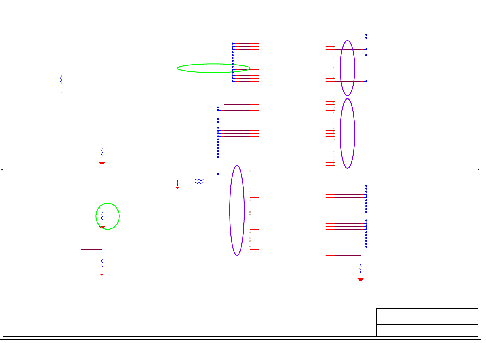
PCI Express Configuration Select
CFG0 1 : Single PEG
0 : Bifurcation enable
3393727 The VIL Voltage DC Specification for CFG[0] Pin is in Violation of the
EDS Value by a Large Amount
The Clarksfield EDS Vol1 documents the CFG[1:0] pins for PCI Express Port
Bifurcation, the straps may not work correctly when using a pull down resistor
of value other than 250 Ohms to drive a value of zero on the CFG[0] pin. When
left floating a value of one is sensed and there is no impact in this case.
D D
CFG0
12
R1272
R1272
NC_3.01K_F
NC_3.01K_F
0402
0402
CFG3 PCI Express Static Lane Reversal
CFG3 1 : Normal Operation
C C
B B
0 : Lane Numbers Reversed
15 ->0 , 14-> 1 , ...
CFG3
12
R1273
R1273
3.01K_F
3.01K_F
0402
0402
CFG4 Display Port Presence
CFG4 1 : Disabled ; No Physical Display Port
attached to Embedded Display Port
0 : Enable ; An external Display Port device
is connected to the Embedded Display Port
CFG4
12
R1274
R1274
NC_3.3K_J
NC_3.3K_J
0402
0402
EVT
CFG7
12
R1289
R1289
NC_3.01K_F
NC_3.01K_F
0402
0402
4
20MIL
20MIL
TP305
TP305
20MIL
20MIL
TP307
TP307
20MIL
20MIL
TP306
TP306
20MIL
20MIL
TP308
TP308
20MIL
20MIL
TP310
TP310
20MIL
20MIL
TP309
TP309
20MIL
20MIL
TP311
TP311
20MIL
20MIL
TP312
TP312
20MIL
20MIL
TP1220
TP1220
20MIL
20MIL
TP1221
TP1221
20MIL
20MIL
TP300
TP300
20MIL
20MIL
TP302
TP321
TP321
TP320
TP320
TP323
TP323
TP325
TP325
TP313
TP313
TP315
TP315
TP314
TP314
TP316
TP316
TP317
TP317
TP318
TP318
TP353
TP353
TP354
TP354
TP355
TP355
TP356
TP356
TP357
TP357
TP425
TP425
20MIL
20MIL
20MIL
20MIL
TP302
TP303
TP303
TP304
TP304
EVT
20MIL
20MIL
20MIL
20MIL
20MIL
20MIL
20MIL
20MIL
20MIL
20MIL
20MIL
20MIL
20MIL
20MIL
20MIL
20MIL
20MIL
20MIL
20MIL
20MIL
20MIL
20MIL
20MIL
20MIL
20MIL
20MIL
20MIL
20MIL
20MIL
20MIL
20MIL
R1583 0_J 0402R1583 0_J 0402
R1584 0_J 0402R1584 0_J 0402
20MIL
1 2
1 2
DVT
3
U67E
U67E
RSVD32
1
AP25
1
1
1
1
1
1
1
1
1
1
1
1
1
CFG0
1
1
CFG3
CFG4
1
1
CFG7
1
1
1
1
1
1
1
1
1
1
1
1
RSVD1
AL25
RSVD2
AL24
RSVD3
AL22
RSVD4
AJ33
RSVD5
AG9
RSVD6
M27
RSVD7
L28
RSVD8
J17
RSVD9
H17
RSVD10
G25
RSVD11
G17
RSVD12
E31
RSVD13
E30
RSVD14
AM30
CFG[0]
AM28
CFG[1]
AP31
CFG[2]
AL32
CFG[3]
AL30
CFG[4]
AM31
CFG[5]
AN29
CFG[6]
AM32
CFG[7]
AK32
CFG[8]
AK31
CFG[9]
AK28
CFG[10]
AJ28
CFG[11]
AN30
CFG[12]
AN32
CFG[13]
AJ32
CFG[14]
AJ29
CFG[15]
AJ30
CFG[16]
AK30
CFG[17]
H16
RSVD_TP_86
B19
RSVD15
A19
RSVD16
A20
RSVD17
B20
RSVD18
U9
RSVD19
T9
RSVD20
AC9
RSVD21
AB9
RSVD22
C1
RSVD_NCTF_23
A3
RSVD_NCTF_24
J29
RSVD26
J28
RSVD27
A34
RSVD_NCTF_28
A33
RSVD_NCTF_29
C35
RSVD_NCTF_30
B35
RSVD_NCTF_31
CPU SOCKET_989P
CPU SOCKET_989P
FOX_PZ98927-3641-01F
FOX_PZ98927-3641-01F
RESERVED
RESERVED
RSVD33
RSVD34
RSVD35
RSVD36
RSVD_NCTF_37
RSVD38
RSVD39
RSVD_NCTF_40
RSVD_NCTF_41
RSVD_NCTF_42
RSVD_NCTF_43
RSVD45
RSVD46
RSVD47
RSVD48
RSVD49
RSVD50
RSVD51
RSVD52
RSVD53
RSVD_NCTF_54
RSVD_NCTF_55
RSVD_NCTF_56
RSVD_NCTF_57
RSVD58
RSVD_TP_59
RSVD_TP_60
RSVD62
RSVD63
RSVD64
RSVD65
RSVD_TP_66
RSVD_TP_67
RSVD_TP_68
RSVD_TP_69
RSVD_TP_70
RSVD_TP_71
RSVD_TP_72
RSVD_TP_73
RSVD_TP_74
RSVD_TP_75
RSVD_TP_76
RSVD_TP_77
RSVD_TP_78
RSVD_TP_79
RSVD_TP_80
RSVD_TP_81
RSVD_TP_82
RSVD_TP_83
RSVD_TP_84
RSVD_TP_85
KEY
VSS
AJ13
AJ12
AH25
AK26
AL26
AR2
AJ26
AJ27
AP1
AT2
AT3
AR1
AL28
AL29
AP30
AP32
AL27
AT31
AT32
AP33
AR33
AT33
AT34
AP35
AR35
AR32
E15
F15
A2
D15
C15
AJ15
AH15
AA5
AA4
R8
AD3
AD2
AA2
AA1
R9
AG7
AE3
V4
V5
N2
AD5
AD7
W3
W2
N3
AE5
AD9
AP34
2
1
1
1
1
TP238
TP238
TP240
TP240
TP241
TP241
TP258
TP258
20MIL
20MIL
20MIL
20MIL
20MIL
20MIL
20MIL
20MIL
1
DVT
1
TP261
TP261
20MIL
20MIL
DVT
1
1
1
1
1
1
1
1
1
1
1
1
1
1
1
1
1
1
1
1
12
20MIL
20MIL
TP331
TP331
20MIL
20MIL
TP332
TP332
20MIL
20MIL
TP333
TP333
20MIL
20MIL
TP334
TP334
20MIL
20MIL
TP335
TP335
20MIL
20MIL
TP336
TP336
20MIL
20MIL
TP337
TP337
20MIL
20MIL
TP338
TP338
20MIL
20MIL
TP339
TP339
20MIL
20MIL
TP340
TP340
20MIL
20MIL
TP341
TP341
20MIL
20MIL
TP342
TP342
20MIL
20MIL
TP343
TP343
20MIL
20MIL
TP344
TP344
20MIL
20MIL
TP347
TP347
20MIL
20MIL
TP348
TP348
20MIL
20MIL
TP349
TP349
20MIL
20MIL
TP350
TP350
20MIL
20MIL
TP345
TP345
20MIL
20MIL
TP346
TP346
VSS (AP34) can be left NC is
0402
0402
CRB implementation; EDS/DG
0_J
0_J
recommendation to GND
R1582
R1582
2611030 PCI Express Interface May Not Meet PCI Express 2.0 Jitter
Specifications
A A
Intel has determined that the workaround (3.01K pull down to Vss on
signal CFG[7]) is not robust. Intel recommends not implementing this
workaround at this time (CFG[7] should not be pulled down).
Intel recommends not to test for PCI-E Express 2.0 Jitter specification
compliance for the affected steppings.
5
4
HON HAI Precision Ind. Co., Ltd.
HON HAI Precision Ind. Co., Ltd.
FOXCONN
FOXCONN
FOXCONN
Title
Title
Title
ARD (RESERVED)
ARD (RESERVED)
ARD (RESERVED)
Size Document Number Rev
Size Document Number Rev
Size Document Number Rev
A3
A3
A3
M960&M970 H Model SA
M960&M970 H Model SA
M960&M970 H Model SA
Date: Sheet of
Date: Sheet
3
2
Date: Sheet
HON HAI Precision Ind. Co., Ltd.
CCPBG - R&D Division
CCPBG - R&D Division
CCPBG - R&D Division
of
of
986Thursday, December 24, 2009
986Thursday, December 24, 2009
1
986Thursday, December 24, 2009
Page 10

5
RTCRST#
VccRTC
+ECVCC VCCRTC
D D
TP118tpc40b_50 TP118tpc40b_50
FOX_HS8202E-LH
FOX_HS8202E-LH
HEADER_2P
HEADER_2P
34
SMDFIX1
SMDFIX1
RTC1
2
1
CN26
CN26
SMDFIX2
SMDFIX2
EVT
C C
IHDA_BITCLK
R618 68_J 0402R618 68_J 0402
1 2
12
C6352
C6352
33P_50V_J
33P_50V_J
0402_NPO
0402_NPO
IHDA_SDATAO
IHDA_RESET#
B B
R633 33_J 0402R633 33_J 0402
1 2
R288 33_J 0402R288 33_J 0402
1 2
HDA_CODEC_SYNC61
18~25mS
D17
D17
21
12
C723
12
R565
R565
1M_J
1M_J
0402
0402
Stuff for No-reboot
Low=Default
High=No-reboot
C6353
C6353
22P_50V_J
22P_50V_J
0402_NPO
0402_NPO
HDA_CODEC_SDATAOUT 61
HDA_CODEC_RST# 61
R634 33_J 0402R634 33_J 0402
1 2
R1553 15_F 0402R1553 15_F 0402
1 2
C723
1U_6.3V_M
1U_6.3V_M
0402_X5R
0402_X5R
R529
R529
1 2
20K_F
20K_F
0402
0402
HDA_CODEC_BITCLK 61
MP
SD103AWS
SD103AWS
null
null
1
12
R650
R650
510_F
510_F
0402
0402
RTC2
12
R649
R649
510_F
510_F
0402
0402
12
For EMI
SPI0_MISO_R SPI_MISO_L
12
C392
C392
1U_6.3V_K
1U_6.3V_K
0402_X5R
0402_X5R
R773
R773
1 2
20K_J
20K_J
0402
0402
HDA_SPKR
IHDA_SYNCIHDA_SYNC
32.768KHZ_12.5P_10PPM
32.768KHZ_12.5P_10PPM
+3VRUN
HDA_DOCK_RST#
The traces inside this
block should be wider.
Q13MC3061001800
Q13MC3061001800
21
JP1
JP1
OPEN_JUMP_OPEN2
OPEN_JUMP_OPEN2
12
12
R297
R297
NC_10K_J
NC_10K_J
0402
0402
+3VALW
12
+3VRUN
12
R299
R299
NC_1K_J
NC_1K_J
0402
0402
1 2
Y4
Y4
1 2
C876
C876
1U_6.3V_M
1U_6.3V_M
0402_X5R
0402_X5R
R298
R298
10K_J
10K_J
0402
0402
12
R5905
R5905
51_J
51_J
0402
0402
C727
C727
15P_50V_K_N
15P_50V_K_N
0402_NPO
0402_NPO
C702
C702
15P_50V_K_N
15P_50V_K_N
0402_NPO
0402_NPO
JTAG_TCK
EVT
VCC0
12
R38
R38
1K_J
1K_J
0402
0402
HOLD0#
VCC0
12
C428
C428
4.7U_10V_K
4.7U_10V_K
0805_X5R
0805_X5R
A A
12
C424
C424
1U_10V_K
1U_10V_K
0603_X5R
0603_X5R
5
U98 SPI ROM-0
VCC0
12
12
+3VRUN VCC0
R5369
R5369
3.3K_J
3.3K_J
SPI0_CS#
0402
0402
SPI0_MISO_R
WP#0
R5372
R5372
NC_1K_J
NC_1K_J
0402
0402
R1557
R1557
0_J 0402
0_J 0402
1 2
D23
D23
21
null
null
NC_SD103AWS
NC_SD103AWS
U98
U98
1
CS#
VCC
2
DO/IO1
HOLD#/IO3
3
WP#/IO2
CLK
GND4DI/IO0
FLASH_SOIC-8P_32MB
FLASH_SOIC-8P_32MB
W25Q32BVSSIG
W25Q32BVSSIG
U98 Normal Support - 32Mbit
(13-W25032B-7000)
23
VCCRTC
20MIL
20MIL
20MIL
20MIL
20MIL
20MIL
PVT
8
7
6
5
DVT
HDA_CODEC_SDATAIN061
20MIL
20MIL
20MIL
20MIL
20MIL
20MIL
20MIL
20MIL
20MIL
20MIL
DVT
14
R545 0_J 0402R545 0_J 0402
TP1086
TP1086
TP174
TP174
TP166
TP166
VCC0
HOLD0#
SPI0_CLK
SPI0_MOSI
4
RTC_32KX1
6 mils
12
SRTCRST#
SM_INTRUDER#
R279 330K_F 0402R279 330K_F 0402
1 2
HDA_SPKR61
1
20MIL
20MIL
1
1
1
TP158
TP158
1
TP160
TP160
1
TP159
TP159
1
TP164
TP164
1
TP168
TP168
20MIL
20MIL
TP169
TP169
EVT
4
R549
R549
10M_J
10M_J
0402
0402
1 2
RTC_32KX2RTC_32KX2_R
RTCRST#
INTVRMEN
IHDA_BITCLK
IHDA_SYNC
HDA_SPKR
IHDA_RESET#
1
TP155
TP155
TP_HDA_SDIN3
IHDA_SDATAO
HDA_DOCK_EN#
HDA_DOCK_RST#
JTAG_TCK
JTAG_TMS
JTAG_TDI
JTAG_TDO
JTAG_RST#
SPI0_CLK
SPI_ROM_CS0#
1
SPI0_MOSI
SPI_MISO_L
0402
0402
100K_J
100K_J
R5969
R5969
U69A
U69A
B13
RTCX1
D13
RTCX2
C14
RTCRST#
D17
SRTCRST#
A16
INTRUDER#
A14
INTVRMEN
A30
HDA_BCLK
D29
HDA_SYNC
P1
SPKR
C30
HDA_RST#
G30
HDA_SDIN0
F30
HDA_SDIN1
E32
HDA_SDIN2
F32
HDA_SDIN3
B29
HDA_SDO
H32
HDA_DOCK_EN# / GPIO33
J30
HDA_DOCK_RST# / GPIO13
M3
JTAG_TCK
K3
JTAG_TMS
K1
JTAG_TDI
J2
JTAG_TDO
J4
JTAG_RST#
BA2
SPI_CLK
AV3
SPI_CS0#
AY3
SPI_CS1#
AY1
SPI_MOSI
AV1
SPI_MISO
Ibexpeak-M
Ibexpeak-M
null
null
12
12
0402
0402
100K_J
100K_J
R5970
R5970
0402
0402
100K_J
100K_J
R5971
R5971
12
SPI0_MOSI
SPI0_CLK
SPI0_CS#
DVT
RTCIHDA
RTCIHDA
SPI JTAG
SPI JTAG
FWH0 / LAD0
FWH1 / LAD1
FWH2 / LAD2
FWH3 / LAD3
FWH4 / LFRAME#
LDRQ1# / GPIO23
LPC
LPC
SATA0RXN
SATA0RXP
SATA0TXN
SATA0TXP
SATA1RXN
SATA1RXP
SATA1TXN
SATA1TXP
SATA2RXN
SATA2RXP
SATA2TXN
SATA2TXP
SATA3RXN
SATA3RXP
SATA3TXN
SATA3TXP
SATA4RXN
SATA4RXP
SATA4TXN
SATA
SATA
SATA4TXP
SATA5RXN
SATA5RXP
SATA5TXN
SATA5TXP
SATAICOMPO
SATAICOMPI
SATALED#
SATA0GP / GPIO21
SATA1GP / GPIO19
LDRQ0#
SERIRQ
D33
B33
C32
A32
C34
A34
F34
AB9
AK7
AK6
AK11
AK9
AH6
AH5
AH9
AH8
AF11
AF9
AF7
AF6
AH3
AH1
AF3
AF1
AD9
AD8
AD6
AD5
AD3
AD1
AB3
AB1
AF16
AF15
T3
Y9
V1
LPC_AD0
LPC_AD1
LPC_AD2
LPC_AD3
LPC_FRAME#
LPC_DRQ#0
1
INT_SERIRQ
VCC_SATA
SATA0GP
SATA1GP
3
20MIL
20MIL
TP110
TP110
SATA_RXN0
SATA_RXP0
SATA_TXN0
SATA_TXP0
SATA_RXN1
SATA_RXP1
SATA_TXN1
SATA_TXP1
SATA_RXN5
SATA_RXP5
SATA_TXN5
SATA_TXP5
R873 37.4_F 0402R873 37.4_F 0402
1 2
+3VRUN
3
LPC_AD0 39,42
LPC_AD1 39,42
LPC_AD2 39,42
LPC_AD3 39,42
LPC_FRAME# 39,42
LPC_DRQ#0 42
INT_SERIRQ 39,42
12
R5910
R5910
NC_10K_J
NC_10K_J
0402
0402
DVT
EVT
SATA_RXN0 47
SATA_RXP0 47
SATA_TXN0 47
SATA_TXP0 47
SATA_RXN1 48
SATA_RXP1 48
SATA_TXN1 48
SATA_TXP1 48
SATA_RXN5 49
SATA_RXP5 49
SATA_TXN5 49
SATA_TXP5 49
SATA_LED# 55
INT_SERIRQ
SATA0GP
SATA1GP
R872 10K_J 0402R872 10K_J 0402
1 2
R904 10K_J 0402R904 10K_J 0402
1 2
R963 10K_J 0402R963 10K_J 0402
1 2
+1.05V_VCC_SATA
2
+3VRUN
[HDA_DOCK_EN#/GPIO33]
Low (0) – Flash Descriptor Security will be overridden. Also, when
this signals is sampled on the rising edge of PWROK then it will also
disable Intel ME and its features.
High (1) – Security measure defined in the Flash Descriptor will be
enabled
12
R158
R158
NC_4.7K_J
NC_4.7K_J
0402
0402
1
+3VRUN
G
G
12
32
D
D
S
S
R154
R154
1K_J
1K_J
0402
0402
Q12
Q12
2N7002W
2N7002W
null
null
R156
R156
1 2
0_J 0402
0_J 0402
HDA_DOCK_EN#
+ECVCC
R155
R155
100_J
100_J
0402
0402
FW_HW39
1 2
EXTERNAL SPI0 ROM INTERFACE(FOR U98)
+ECVCC
SPI0_CLK
SPI0_MOSI
SPI0_MISO_R
SPI_ROM_CS0#
12
CARD_INSERT0
SPI_ROM_CS0#
R542
R542
NC_10K_J
NC_10K_J
0402
0402
MB_FLASH0_EN
CARD_INSERT0
MB_FLASH0_EN15
12
11
10
PVT
53
1
2
R1551 0_J 0402R1551 0_J 0402
1 2
SMDFIX2
SMDFIX2
CN18
CN18
FOX_GB5RF120-1203-7F
FOX_GB5RF120-1203-7F
NC_FPC_12P
NC_FPC_12P
9
8
7
6
5
4
3
2
1
SMDFIX1
SMDFIX1
13 14
+ECVCC
SPI0_CS#
4
U43
U43
NC_MC74HC1G32DTT1G
NC_MC74HC1G32DTT1G
DVT
12
C815
C815
NC_0.1U_16V_Y
NC_0.1U_16V_Y
0402_Y5V
0402_Y5V
MP
MP
EVT
FOXCONN
FOXCONN
FOXCONN
Title
Title
Title
Size Document Number Rev
Size Document Number Rev
Size Document Number Rev
Custom
Custom
Custom
Date: Sheet
Date: Sheet
2
Date: Sheet
1
12
R1613
R1613
NC_1K_J
NC_1K_J
0402
0402
HON HAI Precision Ind. Co., Ltd.
HON HAI Precision Ind. Co., Ltd.
HON HAI Precision Ind. Co., Ltd.
CCPBG - R&D Division
CCPBG - R&D Division
PCH (HDA,JTAG,SAT)
PCH (HDA,JTAG,SAT)
PCH (HDA,JTAG,SAT)
M960&M970 H Model SA
M960&M970 H Model SA
M960&M970 H Model SA
CCPBG - R&D Division
1
10 86Tuesday, December 29, 2009
10 86Tuesday, December 29, 2009
10 86Tuesday, December 29, 2009
of
of
of
Page 11

1
2
3
4
5
6
7
8
U69B
PCI-E Port Table
Port
A A
B B
C C
+1_05V_VTT
D D
Function
Port1 WLAN
Port2
Ricoh R5U231
Port3
GbE LAN
Port4
NC
NC
Port5
Port6
ExpressCard/34 (PCIE)
Port7
NC
Port8
NC
R579 10K_J 0402R579 10K_J 0402
+3VSUS
R577
+3VALW
WLAN_CLKREQ#
R5579 10K_J 0402R5579 10K_J 0402
+3VRUN
CARD_CLK_REQ#
CARD_CLK_REQ#
R537 10K_J 0402R537 10K_J 0402
+3VRUN
CLK_REQ_LAN#
R539 10K_J 0402R539 10K_J 0402
+3VRUN
R540 10K_J 0402R540 10K_J 0402
+3VRUN
R555
R556 10K_J 0402R556 10K_J 0402
+3VALW
EXPRESS_DET#
1 2
NC_10K_J
NC_10K_J
0402R577
0402
1 2
1 2
R5578 NC_10K_J 0402R5578 NC_10K_J 0402
1 2
1 2
1 2
NC_10K_J
NC_10K_J
0402R555
0402
1 2
1 2
1
EVT
WLAN_CLKREQ# 44
1 2
CARD_CLK_REQ# 50
CLK_REQ_LAN# 45
PCIECLKRQ3#
PCIECLKRQ4#
EXPRESS_DET# 43
EVT
2
WLAN_RXN144
WLAN_RXP144
WLAN_TXN144
WLAN_TXP144
CARD_RXN250
CARD_RXP250
CARD_TXN250
CARD_TXP250
LAN_RXN345
LAN_RXP345
LAN_TXN345
LAN_TXP345
20MIL
20MIL
20MIL
20MIL
20MIL
20MIL
20MIL
20MIL
EXPRESS_RXN643
EXPRESS_RXP643
EXPRESS_TXN643
EXPRESS_TXP643
C889 0.1U_6.3V_K 0402_X5RC889 0.1U_6.3V_K 0402_X5R
1 2
C890 0.1U_6.3V_K 0402_X5RC890 0.1U_6.3V_K 0402_X5R
1 2
C704 0.1U_6.3V_K 0402_X5RC704 0.1U_6.3V_K 0402_X5R
1 2
C701 0.1U_6.3V_K 0402_X5RC701 0.1U_6.3V_K 0402_X5R
1 2
C679 0.1U_6.3V_K 0402_X5RC679 0.1U_6.3V_K 0402_X5R
1 2
C680 0.1U_6.3V_K 0402_X5RC680 0.1U_6.3V_K 0402_X5R
1 2
1
TP1085
TP1085
1
TP1082
TP1082
1
TP1083
TP1083
1
TP1084
TP1084
C675 0.1U_6.3V_K 0402_X5RC675 0.1U_6.3V_K 0402_X5R
1 2
C676 0.1U_6.3V_K 0402_X5RC676 0.1U_6.3V_K 0402_X5R
1 2
WLAN_TXN1_C
WLAN_TXP1_C
CARD_TXN2_C
CARD_TXP2_C
LAN_TXN3_C
LAN_TXP3_C
EVT
EXPRESS_TXN6_C
EXPRESS_TXP6_C
EVT
RP69 0 0404_4P2RRP69 0 0404_4P2R
CLK_PCIE_WLAN#44
CLK_PCIE_WLAN44
CLK_PCIE_CARD#50
CLK_PCIE_CARD50
CLK_PCIE_LAN#45
CLK_PCIE_LAN45
1
2 3
RP71 0
RP71 0
2 3
1
0404_4P2R
0404_4P2R
RP67 0
RP67 0
2 3
1
0404_4P2R
0404_4P2R
R_PCIE_WLAN#
4
R_PCIE_WLAN
WLAN_CLKREQ#
R_PCIE_CARD#
R_PCIE_CARD
4
CARD_CLK_REQ#
4
CLK_REQ_LAN#
R_PCIE_LAN#
R_PCIE_LAN
PCIECLKRQ3#
DVT
TP1125
TP1125
1
2 3
1
R_PCIE_EXPRESS#
4
R_PCIE_EXPRESS
EXPRESS_DET#
20MIL
20MIL
CLK_PCIE_EXPRESS#43
CLK_PCIE_EXPRESS43
RP68 0 0404_4P2RRP68 0 0404_4P2R
PCIECLKRQ4#
DVT
R5421 10K_J 0402R5421 10K_J 0402
+3VALW
1 2
3
PEG_B_CLKREQ#
U69B
BG30
PERN1
BJ30
PERP1
BF29
PETN1
BH29
PETP1
AW30
PERN2
BA30
PERP2
BC30
PETN2
BD30
PETP2
AU30
PERN3
AT30
PERP3
AU32
PETN3
AV32
PETP3
BA32
PERN4
BB32
PERP4
BD32
PETN4
BE32
PETP4
BF33
PERN5
BH33
PERP5
BG32
PETN5
BJ32
PETP5
BA34
PERN6
AW34
PERP6
BC34
PETN6
BD34
PETP6
AT34
PERN7
AU34
PERP7
AU36
PETN7
AV36
PETP7
BG34
PERN8
BJ34
PERP8
BG36
PETN8
BJ36
PETP8
AK48
CLKOUT_PCIE0N
AK47
CLKOUT_PCIE0P
P9
PCIECLKRQ0# / GPIO73
AM43
CLKOUT_PCIE1N
AM45
CLKOUT_PCIE1P
U4
PCIECLKRQ1# / GPIO18
AM47
CLKOUT_PCIE2N
AM48
CLKOUT_PCIE2P
N4
PCIECLKRQ2# / GPIO20
AH42
CLKOUT_PCIE3N
AH41
CLKOUT_PCIE3P
A8
PCIECLKRQ3# / GPIO25
AM51
CLKOUT_PCIE4N
AM53
CLKOUT_PCIE4P
M9
PCIECLKRQ4# / GPIO26
AJ50
CLKOUT_PCIE5N
AJ52
CLKOUT_PCIE5P
H6
PCIECLKRQ5# / GPIO44
AK53
CLKOUT_PEG_B_N
AK51
CLKOUT_PEG_B_P
P13
PEG_B_CLKRQ# / GPIO56
Ibexpeak-M
Ibexpeak-M
null
null
SMB_CLK_R
SMB_DATA_R
PCI-E*
PCI-E*
Controller
Controller
PEG
PEG
CLKOUT_DP_N / CLKOUT_BCLK1_N
CLKOUT_DP_P / CLKOUT_BCLK1_P
From CLK BUFFER
From CLK BUFFER
Clock Flex
Clock Flex
U6
U6
8
VCC
6
SCL
5
SDA
4
VSS
EEPROM_SOP-8_256x8
EEPROM_SOP-8_256x8
HT24LC02
HT24LC02
SMBus Address: AEH
4
SMBALERT# / GPIO11
SML0ALERT# / GPIO60
SML1ALERT# / GPIO74
SMBus
SMBus
SML1CLK / GPIO58
SML1DATA / GPIO75
Link
Link
PEG_A_CLKRQ# / GPIO47
CLKOUT_PEG_A_N
CLKOUT_PEG_A_P
CLKIN_SATA_N / CKSSCD_N
CLKIN_SATA_P / CKSSCD_P
CLKIN_PCILOOPBACK
CLKOUTFLEX0 / GPIO64
CLKOUTFLEX1 / GPIO65
CLKOUTFLEX2 / GPIO66
CLKOUTFLEX3 / GPIO67
+3VRUN
7
WP
1
A0
2
A1
3
A2
SMBCLK
SMBDATA
SML0CLK
SML0DATA
CL_CLK1
CL_DATA1
CL_RST1#
CLKOUT_DMI_N
CLKOUT_DMI_P
CLKIN_DMI_N
CLKIN_DMI_P
CLKIN_BCLK_N
CLKIN_BCLK_P
CLKIN_DOT_96N
CLKIN_DOT_96P
REFCLK14IN
XTAL25_IN
XTAL25_OUT
XCLK_RCOMP
12
C23
C23
0.1U_16V_Y
0.1U_16V_Y
0402_Y5V
0402_Y5V
B9
H14
C8
J14
C6
G8
M14
E10
G12
T13
T11
T9
H1
AD43
AD45
AN4
AN2
AT1
AT3
AW24
BA24
AP3
AP1
F18
E18
AH13
AH12
P41
J42
AH51
AH53
AF38
T45
P43
T42
N50
5
WAKE_SCI#
SMB_CLK_R
SMB_DATA_R
GPIO60
SML0_CLK
SML0_DATA
LPD_SPI_INTR#
SMB_THRM_CLK
SMB_THRM_DATA
PEG_CLKREQ#
CLK_PEG#
CLK_PEG
XTAL25_IN
XTAL25_OUT
XCLK_RCOMP
WAKE_SCI# 39
PCH EEPROM/CKG/DIMM/ExpressCard
SMB_THRM_CLK 24,39,58
SMB_THRM_DATA 24,39,58
RP89 0 0404_4P2RRP89 0 0404_4P2R
1
4
2 3
CLK_EXP_N 4
CLK_EXP_P 4
CLK_DMI_PCH# 19
CLK_DMI_PCH 19
CLK_PCH_BCLK# 19
CLK_PCH_BCLK 19
DREFCLK# 19
DREFCLK 19
CLK_PCIE_SATA# 19
CLK_PCIE_SATA 19
REF_14M_PCH 19
CLK_PCI_FB 14
+1_05VRUN_SSCVCC
R1225 90.9_F 0402R1225 90.9_F 0402
R899 10K_J 0402R899 10K_J 0402
EC/Thermal Sensor
1 2
PCIE_REFCLK# 22
PCIE_REFCLK 22
2009/11/19 Add reserve 10k pull-low resistor for Intel FCIM function
EVT
1 2
Calpella Platform – Design Guide - Addendum /
Update – Rev. 1.52 (Doc #414044).).
XTAL_IN should be pulled to GND via a 0ohm by
default.
This pull-down resistor on XTAL_IN should only
be un-stuffed when 25MHz crystal is used.
6
R1651
R1651
0_J
0_J
0402
0402
XTAL25_IN
XTAL25_OUT
R813 NC_0_J 0402R813 NC_0_J 0402
GPIO60
WAKE_SCI#
LPD_SPI_INTR#
SML0_CLK
SML0_DATA
CLK_DMI_PCH#
CLK_DMI_PCH
CLK_PCH_BCLK#
CLK_PCH_BCLK
DREFCLK#
DREFCLK
CLK_PCIE_SATA#
CLK_PCIE_SATA
REF_14M_PCH
R1226
R1226
NC_1M_J
NC_1M_J
0402
0402
12
FOXCONN
FOXCONN
FOXCONN
Title
Title
Title
Size Document Number Rev
Size Document Number Rev
Size Document Number Rev
Custom
Custom
Custom
Date: Sheet
Date: Sheet
Date: Sheet
7
R898 10K_J 0402R898 10K_J 0402
1 2
R892 10K_J 0402R892 10K_J 0402
1 2
R901 10K_J 0402R901 10K_J 0402
1 2
R902 2.2K_J 0402R902 2.2K_J 0402
1 2
R903 2.2K_J 0402R903 2.2K_J 0402
1 2
+3VRUN
12
12
R1594
R1594
R1593
R1593
2.2K_J
2.2K_J
2.2K_J
2.2K_J
0402
0402
0402
0402
SMB_CLK_R
SMB_DATA_R
R5992 NC_10K_J 0402R5992 NC_10K_J 0402
1 2
R5993 NC_10K_J 0402R5993 NC_10K_J 0402
1 2
R5994 NC_10K_J 0402R5994 NC_10K_J 0402
1 2
R5995 NC_10K_J 0402R5995 NC_10K_J 0402
1 2
R5996 NC_10K_J 0402R5996 NC_10K_J 0402
1 2
R5997 NC_10K_J 0402R5997 NC_10K_J 0402
1 2
R5998 NC_10K_J 0402R5998 NC_10K_J 0402
1 2
R5999 NC_10K_J 0402R5999 NC_10K_J 0402
1 2
R6000 NC_10K_J 0402R6000 NC_10K_J 0402
1 2
NC_25MHZ_20P_30PPM
NC_25MHZ_20P_30PPM
ITTI_L5030-25.000-20
ITTI_L5030-25.000-20
Y8
Y8
12
C1288
C1288
NC_18P_50V_J
NC_18P_50V_J
0402_NPO
0402_NPO
PCH (PCI-E,SMBUS,CLK)
PCH (PCI-E,SMBUS,CLK)
PCH (PCI-E,SMBUS,CLK)
M960&M970 H Model SA
M960&M970 H Model SA
M960&M970 H Model SA
+3VALW
DVT
SMB_CLK_R 19,20,21,43
SMB_DATA_R 19,20,21,43
EVT
PVT
C1289
C1289
NC_18P_50V_J
NC_18P_50V_J
0402_NPO
0402_NPO
HON HAI Precision Ind. Co., Ltd.
HON HAI Precision Ind. Co., Ltd.
HON HAI Precision Ind. Co., Ltd.
CCPBG - R&D Division
CCPBG - R&D Division
CCPBG - R&D Division
of
of
of
11 86Tuesday, December 29, 2009
11 86Tuesday, December 29, 2009
11 86Tuesday, December 29, 2009
8
Page 12

1
A A
+1.05V_VCC_EXP
B B
2
DMI_RXN03
DMI_RXN13
DMI_RXN23
DMI_RXN33
DMI_RXP03
DMI_RXP13
DMI_RXP23
DMI_RXP33
DMI_TXN03
DMI_TXN13
DMI_TXN23
DMI_TXN33
DMI_TXP03
DMI_TXP13
DMI_TXP23
DMI_TXP33
R874 49.9_F 0402R874 49.9_F 0402
1 2
DMI_RXN0
DMI_RXN1
DMI_RXN2
DMI_RXN3
DMI_RXP0
DMI_RXP1
DMI_RXP2
DMI_RXP3
DMI_TXN0
DMI_TXN1
DMI_TXN2
DMI_TXN3
DMI_TXP0
DMI_TXP1
DMI_TXP2
DMI_TXP3
DMI_COMP
3
BC24
BJ22
AW20
BJ20
BD24
BG22
BA20
BG20
BE22
BF21
BD20
BE18
BD22
BH21
BC20
BD18
BH25
BF25
U69C
U69C
DMI0RXN
DMI1RXN
DMI2RXN
DMI3RXN
DMI0RXP
DMI1RXP
DMI2RXP
DMI3RXP
DMI0TXN
DMI1TXN
DMI2TXN
DMI3TXN
DMI0TXP
DMI1TXP
DMI2TXP
DMI3TXP
DMI_ZCOMP
DMI_IRCOMP
DMI
DMI
4
FDI
FDI
5
For Disable Arrandale Graphic
In addition, FDI_RXN_[7:0] and FDI_RXP_[7:0] can be left floating on the PCH.
FDI_TX[7:0] and FDI_TX#[7:0] can be left floating on the Arrandale. The
GFX_IMON,FDI_FSYNC[0], FDI_FSYNC[1], FDI_LSYNC[0], FDI_LSYNC[1], and FDI_INT
signals on the Arrandale side should be tied to GND (through 1-kΩ ±5% resistors).
BA18
FDI_RXN0
BH17
FDI_RXN1
BD16
FDI_RXN2
BJ16
FDI_RXN3
BA16
FDI_RXN4
BE14
FDI_RXN5
BA14
FDI_RXN6
BC12
FDI_RXN7
BB18
FDI_RXP0
BF17
FDI_RXP1
BC16
FDI_RXP2
BG16
FDI_RXP3
AW16
FDI_RXP4
BD14
FDI_RXP5
BB14
FDI_RXP6
BD12
FDI_RXP7
BJ14
FDI_INT
FDI_FSYNC0
FDI_FSYNC1
FDI_LSYNC0
FDI_LSYNC1
BF13
BH13
BJ12
BG14
6
7
8
SB_RST#
SYS_PWROK
PWROK
MPWROK_R
MPWROK_R
LAN_RST#
T6
SYS_RESET#
M6
SYS_PWROK
B17
PWROK
K5
MEPWROK
A10
LAN_RST#
D9
DRAMPWROK
C16
RSMRST#
M1
SUS_PWR_ACK / GPIO30
P5
PWRBTN#
P7
ACPRESENT / GPIO31
A6
BATLOW# / GPIO72
F14
RI#
Ibexpeak-M
Ibexpeak-M
null
null
CLKRUN# / GPIO32
SUS_STAT# / GPIO61
SUSCLK / GPIO62
SLP_S5# / GPIO63
System Power Management
System Power Management
SB_RST#42 PCIE_WAKE# 43,44,45
R973
R973
IMVP_PWRGD39,78
R927 0_J 0402R927 0_J 0402
RUN_PWRGD4,39,75,76,80
C C
+3VRUN
R931
R931
NC_10K_J
NC_10K_J
0402
0402
1 2
R923 NC_0_J 0402R923 NC_0_J 0402
1 2
1 2
PM_DRAM_PWRGD4
PM_RSMRST#39
SUS_PWR_ACK39
PWRBTN#39
AC_Present39
LAN_RST#MPWROK_R
SUS_PWR_ACK
PWRBTN#
AC_Present
1 2
2.2K_J 0402
2.2K_J 0402
R972
R972
1 2
2.2K_J 0402
2.2K_J 0402
R918 NC_0_J 0402R918 NC_0_J 0402
1 2
R940 NC_0_J 0402R940 NC_0_J 0402
1 2
R917 10K_J 0402R917 10K_J 0402
1 2
R916
R916
1 2
2.2K_J 0402
2.2K_J 0402
PM_RSMRST#_R
PM_BATLOW#
PM_RI#
EVT
D33
SYS_PWROK
D D
PM_RSMRST#_R
PWROK
1
D33
null
null
SD103AWS
SD103AWS
D28
D28
null
null
SD103AWS
SD103AWS
D29
D29
null
null
SD103AWS
SD103AWS
21
21
21
2
ALW_PWRGD 39,74
3
4
WAKE#
SLP_S4#
SLP_S3#
SLP_M#
TP23
PMSYNCH
SLP_LAN#
J12
Y1
PM_SUS_STAT#
P8
F3
E4
H7
P12
K8
N2
BJ10
F6
PM_CLKRUN#
PM_S4_STATE#
PM_SLP_S5#
PM_SLP_S4#
PM_SLP_S3#
PM_SLP_ME#
PM_SLP_DSW#
H_PM_SYNC
PM_SLP_LAN#
1
1
1
PM_SLP_ME#
5
PM_CLKRUN# 39,42
PM_SUS_STAT# 42
20MIL
20MIL
TP170
TP170
PM_SLP_S5# 39
PM_SLP_S4# 39
PM_SLP_S3# 39
PM_SLP_ME# 39
20MIL
20MIL
TP362
TP362
H_PM_SYNC 4
20MIL
20MIL
TP361
TP361
1
TP171
TP171
20MIL
20MIL
EVT
+3VRUN
SB_RST#
PM_CLKRUN#
PCIE_WAKE#
PM_RI#
PM_SLP_LAN#
PM_BATLOW#
SUS_PWR_ACK
AC_Present
SB_RST#
PM_RSMRST#
PWROK
FOXCONN
FOXCONN
FOXCONN
Title
Title
Title
PCH (DMI,FDI,GPIO)
PCH (DMI,FDI,GPIO)
PCH (DMI,FDI,GPIO)
Size Document Number Rev
Size Document Number Rev
Size Document Number Rev
A3
A3
A3
M960&M970 H Model SA
M960&M970 H Model SA
M960&M970 H Model SA
Date: Sheet
Date: Sheet
6
Date: Sheet
7
R945 8.2K_J 0402R945 8.2K_J 0402
1 2
R912 8.2K_J 0402R912 8.2K_J 0402
1 2
EVT
R911 10K_J 0402R911 10K_J 0402
1 2
R910 10K_J 0402R910 10K_J 0402
1 2
R914 NC_10K_J 0402R914 NC_10K_J 0402
1 2
R913 8.2K_J 0402R913 8.2K_J 0402
1 2
R920 8.2K_J 0402R920 8.2K_J 0402
1 2
R921 10K_J 0402R921 10K_J 0402
1 2
R922 NC_8.2K_J 0402R922 NC_8.2K_J 0402
1 2
R915 10K_J 0402R915 10K_J 0402
1 2
R1576 10K_J 0402R1576 10K_J 0402
1 2
HON HAI Precision Ind. Co., Ltd.
HON HAI Precision Ind. Co., Ltd.
HON HAI Precision Ind. Co., Ltd.
CCPBG - R&D Division
CCPBG - R&D Division
CCPBG - R&D Division
+3VALW
of
of
of
12 86Tuesday, December 29, 2009
12 86Tuesday, December 29, 2009
12 86Tuesday, December 29, 2009
8
Page 13

1
A A
NC for disable LVDS
NC for disable LVDS
B B
C C
Calpella Platform – Design Guide - Addendum
/ Update – Rev. 1.52 (Doc #414044).).
2
20MIL
20MIL
R2231K_J 0402R2231K_J 0402
1 2
3
T48
T47
Y48
AB48
Y45
AB46
V48
AP39
LVDS_VBG
AP41
1
TP151
20MIL
20MIL
20MIL
20MIL
20MIL
20MIL
20MIL
20MIL
TP151
TP154
TP154
TP157
TP157
TP162
TP162
TP165
TP165
CRT_IREF
AT43
AT42
AV53
AV51
BB47
BA52
AY48
1
AV47
BB48
BA50
AY49
AV48
1
AP48
AP47
AY53
AT49
AU52
1
AT53
AY51
AT48
AU50
AT51
1
AA52
AB53
AD53
V51
V53
Y53
Y51
AD48
AB51
4
U69D
U69D
L_BKLTEN
L_VDD_EN
L_BKLTCTL
L_DDC_CLK
L_DDC_DATA
L_CTRL_CLK
L_CTRL_DATA
LVD_IBG
LVD_VBG
LVD_VREFH
LVD_VREFL
LVDSA_CLK#
LVDSA_CLK
LVDSA_DATA#0
LVDSA_DATA#1
LVDSA_DATA#2
LVDSA_DATA#3
LVDSA_DATA0
LVDSA_DATA1
LVDSA_DATA2
LVDSA_DATA3
LVDSB_CLK#
LVDSB_CLK
LVDSB_DATA#0
LVDSB_DATA#1
LVDSB_DATA#2
LVDSB_DATA#3
LVDSB_DATA0
LVDSB_DATA1
LVDSB_DATA2
LVDSB_DATA3
CRT_BLUE
CRT_GREEN
CRT_RED
CRT_DDC_CLK
CRT_DDC_DATA
CRT_HSYNC
CRT_VSYNC
DAC_IREF
CRT_IRTN
Ibexpeak-M
Ibexpeak-M
null
null
DDPB_0N
DDPB_0P
DDPB_1N
DDPB_1P
DDPB_2N
DDPB_2P
DDPB_3N
DDPB_3P
DDPC_0N
DDPC_0P
DDPC_1N
DDPC_1P
DDPC_2N
DDPC_2P
DDPC_3N
DDPC_3P
DDPD_0N
DDPD_0P
DDPD_1N
DDPD_1P
DDPD_2N
DDPD_2P
DDPD_3N
DDPD_3P
BJ46
BG46
BJ48
BG48
BF45
BH45
T51
T53
BG44
BJ44
AU38
BD42
BC42
BJ42
BG42
BB40
BA40
AW38
BA38
Y49
AB49
BE44
BD44
AV40
BE40
BD40
BF41
BH41
BD38
BC38
BB36
BA36
U50
U52
BC46
BD46
AT38
BJ40
BG40
BJ38
BG38
BF37
BH37
BE36
BD36
SDVO_TVCLKINN
SDVO_TVCLKINP
SDVO_STALLN
SDVO_STALLP
SDVO_INTN
SDVO_INTP
SDVO_CTRLCLK
SDVO_CTRLDATA
DDPB_AUXN
DDPB_AUXP
DDPB_HPD
LVDS
LVDS
DDPC_CTRLCLK
DDPC_CTRLDATA
DDPC_AUXN
DDPC_AUXP
DDPC_HPD
Digital Display Interface
Digital Display Interface
DDPD_CTRLCLK
DDPD_CTRLDATA
DDPD_AUXN
DDPD_AUXP
DDPD_HPD
CRT
CRT
5
DDPD_HPD
1
1
1
1
1
1
1
1
1
1
20MIL
20MIL
TP77
TP77
20MIL
20MIL
TP78
TP78
20MIL
20MIL
TP79
TP79
20MIL
20MIL
TP81
TP81
20MIL
20MIL
TP82
TP82
20MIL
20MIL
TP83
TP83
20MIL
20MIL
TP84
TP84
20MIL
20MIL
TP85
TP85
20MIL
20MIL
TP95
TP95
20MIL
20MIL
TP96
TP96
1
TP1219
TP1219
20MIL
20MIL
6
7
8
EVT
D D
HON HAI Precision Ind. Co., Ltd.
HON HAI Precision Ind. Co., Ltd.
FOXCONN
FOXCONN
FOXCONN
Title
Title
Title
PCH (LVDS,DDI)
PCH (LVDS,DDI)
PCH (LVDS,DDI)
Size Document Number Rev
Size Document Number Rev
Size Document Number Rev
Custom
Custom
Custom
M960&M970 H Model SA
M960&M970 H Model SA
M960&M970 H Model SA
Date: Sheet
Date: Sheet
1
2
3
4
5
6
Date: Sheet
7
HON HAI Precision Ind. Co., Ltd.
CCPBG - R&D Division
CCPBG - R&D Division
CCPBG - R&D Division
13 86Thursday, December 24, 2009
13 86Thursday, December 24, 2009
13 86Thursday, December 24, 2009
of
of
of
8
Page 14
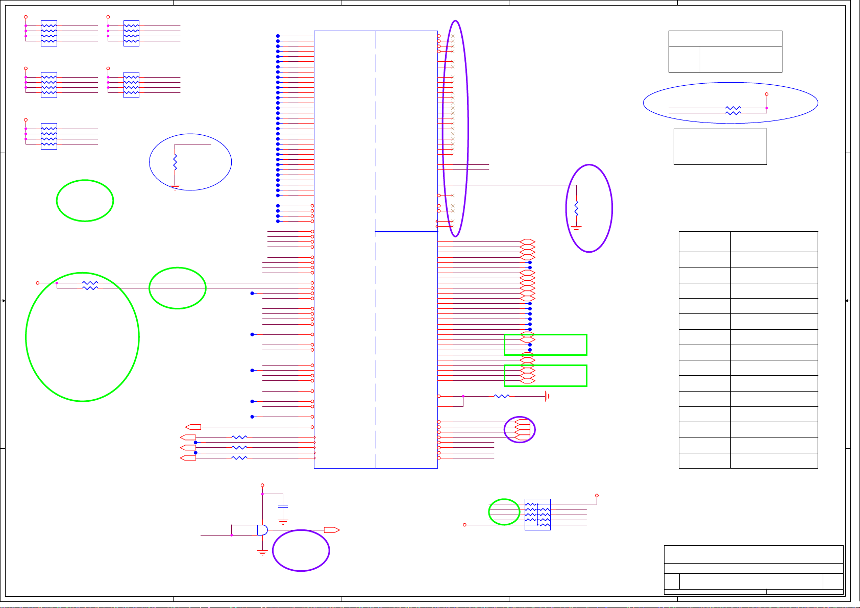
5
+3VRUN +3VRUN
RP13
RP13
8
INT_PIRQD#
7
6
8.2K
8.2K
0804_8P4R
0804_8P4R
RP17
RP17
8
INT_PIRQF#
7
INT_PIRQB#
6
8.2K
8.2K
0804_8P4R
0804_8P4R
RP14
RP14
8
PCI_DEVSEL#
7
6
8.2K
8.2K
0804_8P4R
0804_8P4R
R345
R346 NC_10K_J 0402R346 NC_10K_J 0402
PCI_REQ#2
PCI_IRDY#
PCI_STOP#
PCI_REQ#3
PCI_REQ#0
PCI_PERR#
PCI_SERR#
PCI_LOCK#
NC_10K_J
NC_10K_J
1 2
1 2
1
2
3
4 5
+3VRUN
1
+3VRUN
+3VRUN
2
3
4 5
1
2
3
4 5
D D
C C
+3VRUN
1
2
3
4 5
1
2
3
4 5
EVT
0402R345
0402
RP15
RP15
8.2K
8.2K
0804_8P4R
0804_8P4R
RP16
RP16
8.2K
8.2K
0804_8P4R
0804_8P4R
INT_PIRQH#
8
PCI_TRDY#
7
PCI_FRAME#
6
PCI_REQ#1
INT_PIRQA#
8
INT_PIRQE#
7
INT_PIRQC#
6
INT_PIRQG#
PCI_GNT#3
12
R1612
R1612
NC_4.7K_J
NC_4.7K_J
0402
0402
20MIL
20MIL
EVT
20MIL
20MIL
20MIL
B B
EVT
PLT_RST#22,42,44,45,50
PCLK_JIG42
20MIL
20MIL
TP132
TP132
CLK_KBCPCI39
20MIL
20MIL
TP129
TP129
CLK_PCI_FB11
A A
5
20MIL
20MIL
20MIL
20MIL
20MIL
R44 22_J0402R44 22_J0402
1
R56 22_J0402R56 22_J0402
1
R1223 22_J0402R1223 22_J0402
U102
U102
74AHC1G08GW
74AHC1G08GW
PLT_RST#
Buffer to reduce loading on PLT_RST#.
TP163
TP163
TP130
TP130
TP127
TP127
TP128
TP128
TP126
TP126
20MIL
20MIL
20MIL
20MIL
20MIL
20MIL
20MIL
20MIL
20MIL
20MIL
20MIL
20MIL
20MIL
20MIL
20MIL
20MIL
20MIL
20MIL
20MIL
20MIL
20MIL
20MIL
20MIL
20MIL
20MIL
20MIL
20MIL
20MIL
20MIL
20MIL
20MIL
20MIL
20MIL
20MIL
20MIL
20MIL
20MIL
20MIL
20MIL
20MIL
20MIL
20MIL
20MIL
20MIL
20MIL
20MIL
20MIL
20MIL
20MIL
20MIL
20MIL
20MIL
20MIL
20MIL
20MIL
20MIL
20MIL
20MIL
20MIL
20MIL
20MIL
20MIL
20MIL
20MIL
20MIL
20MIL
20MIL
20MIL
20MIL
20MIL
20MIL
20MIL
4
+3VALW
1
2
4
TP182
TP182
TP167
TP167
TP186
TP186
TP194
TP194
TP187
TP187
TP199
TP199
TP201
TP201
TP200
TP200
TP202
TP202
TP319
TP319
TP247
TP247
TP322
TP322
TP363
TP363
TP324
TP324
TP426
TP426
TP428
TP428
TP427
TP427
TP429
TP429
TP431
TP431
TP430
TP430
TP432
TP432
TP434
TP434
TP433
TP433
TP435
TP435
TP437
TP437
TP436
TP436
TP438
TP438
TP440
TP440
TP439
TP439
TP441
TP441
TP443
TP443
TP442
TP442
TP446
TP446
TP445
TP445
TP447
TP447
TP444
TP444
INT_PIRQA#
INT_PIRQB#
INT_PIRQC#
INT_PIRQD#
PCI_REQ#0
PCI_REQ#1
PCI_REQ#2
PCI_REQ#3
PCI_GNT#0
PCI_GNT#1
PCI_GNT#2
1
PCI_GNT#3
INT_PIRQE#
INT_PIRQF#
INT_PIRQG#
INT_PIRQH#
PCI_RST#
1
PCI_SERR#
PCI_PERR#
PCI_IRDY#
PCI_PAR
1
PCI_DEVSEL#
PCI_FRAME#
PCI_LOCK#
PCI_STOP#
1
PCI_TRDY#
PME#_ICH
1
PLT_RST#
CLK_PCI_JIG
CLK_PCI_KBC
CLK_PCI_FB_R
53
4
1
H40
1
N34
1
C44
1
A38
1
C36
1
J34
1
A40
1
D45
1
E36
1
H48
1
E40
1
C40
1
M48
1
M45
1
F53
1
M40
1
M43
1
J36
1
K48
1
F40
1
C42
1
K46
1
M51
1
J52
1
K51
1
L34
1
F42
1
J40
1
G46
1
F44
1
M47
1
H36
1
J50
1
G42
1
H47
1
G34
G38
H51
B37
A44
F51
A46
B45
M53
F48
K45
F36
H53
B41
K53
A36
A48
K6
E44
E50
A42
H44
F46
C46
D49
D41
C48
M7
D5
N52
P53
P46
P51
P48
12
C1359
C1359
0.1U_6.3V_K
0.1U_6.3V_K
0402_X5R
0402_X5R
BUF_PLT_RST#
U69E
U69E
AD0
AD1
AD2
AD3
AD4
AD5
AD6
AD7
AD8
AD9
AD10
AD11
AD12
AD13
AD14
AD15
AD16
AD17
AD18
AD19
AD20
AD21
AD22
AD23
AD24
AD25
AD26
AD27
AD28
AD29
AD30
AD31
C/BE0#
C/BE1#
C/BE2#
C/BE3#
PIRQA#
PIRQB#
PIRQC#
PIRQD#
REQ0#
REQ1# / GPIO50
REQ2# / GPIO52
REQ3# / GPIO54
GNT0#
GNT1# / GPIO51
GNT2# / GPIO53
GNT3# / GPIO55
PIRQE# / GPIO2
PIRQF# / GPIO3
PIRQG# / GPIO4
PIRQH# / GPIO5
PCIRST#
SERR#
PERR#
IRDY#
PAR
DEVSEL#
FRAME#
PLOCK#
STOP#
TRDY#
PME#
PLTRST#
CLKOUT_PCI0
CLKOUT_PCI1
CLKOUT_PCI2
CLKOUT_PCI3
CLKOUT_PCI4
Ibexpeak-M
Ibexpeak-M
null
null
DVT
NV_DQ10 / NV_IO10
NV_DQ11 / NV_IO11
NVRAM
NVRAM
NV_DQ12 / NV_IO12
NV_DQ13 / NV_IO13
NV_DQ14 / NV_IO14
NV_DQ15 / NV_IO15
PCI
PCI
USB
USB
BUF_PLT_RST# 4,39,42,43
3
NV_CE#0
NV_CE#1
NV_CE#2
NV_CE#3
NV_DQS0
NV_DQS1
NV_DQ0 / NV_IO0
NV_DQ1 / NV_IO1
NV_DQ2 / NV_IO2
NV_DQ3 / NV_IO3
NV_DQ4 / NV_IO4
NV_DQ5 / NV_IO5
NV_DQ6 / NV_IO6
NV_DQ7 / NV_IO7
NV_DQ8 / NV_IO8
NV_DQ9 / NV_IO9
NV_ALE
NV_CLE
NV_RCOMP
NV_RB#
NV_WR#0_RE#
NV_WR#1_RE#
NV_WE#_CK0
NV_WE#_CK1
USBP0N
USBP0P
USBP1N
USBP1P
USBP2N
USBP2P
USBP3N
USBP3P
USBP4N
USBP4P
USBP5N
USBP5P
USBP6N
USBP6P
USBP7N
USBP7P
USBP8N
USBP8P
USBP9N
USBP9P
USBP10N
USBP10P
USBP11N
USBP11P
USBP12N
USBP12P
USBP13N
USBP13P
USBRBIAS#
USBRBIAS
OC0# / GPIO59
OC1# / GPIO40
OC2# / GPIO41
OC3# / GPIO42
OC4# / GPIO43
OC5# / GPIO9
OC6# / GPIO10
OC7# / GPIO14
3
DVT
AY9
BD1
AP15
BD8
AV9
BG8
AP7
AP6
AT6
AT9
BB1
AV6
BB3
BA4
BE4
BB6
BD6
BB7
BC8
BJ8
BJ6
BG6
BD3
AY6
AU2
AV7
AY8
AY5
AV11
BF5
H18
J18
A18
C18
N20
P20
J20
L20
F20
G20
A20
C20
M22
N22
B21
D21
H22
J22
E22
F22
A22
C22
G24
H24
L24
M24
A24
C24
B25
D25
N16
J16
F16
L16
E14
G16
F12
T15
+3VALW
NV_ALE
NV_CLE
NV_RCOMP
USB_PN0
USB_PP0
USB_PN1
USB_PP1
USB_PN2
USB_PP2
USB_PN3
USB_PP3
USB_PN4
USB_PP4
USB_PN5
USB_PP5
USB_PN6
USB_PP6
USB_PN7
USB_PP7
USB_PN8
USB_PP8
USB_PN9
USB_PP9
USB_PN10
USB_PP10
USB_PN11
USB_PP11
USB_PN12
USB_PP12
USB_PN13
USB_PP13
USBRBIAS
USB_OC#4
USB_OC#5
USB_OC#6
USB_OC#7
EVT
1 2
22.6_F 0402
22.6_F 0402
USB_OC#0
USB_OC#1
USB_OC#2
USB_OC#3
USB_OC#2
USB_OC#5
USB_OC#4
USB_OC#6
R308
R308
1
1
1
1
1
1
1
1
1
1
RP18
RP18
7
8
9
10
10K
10K
1206_10P8R
1206_10P8R
USB_PN0 49
USB_PP0 49
USB_PN1 61
USB_PP1 61
TP450
TP450
TP451
TP451
USB_PN3 43
USB_PP3 43
USB_PN4 61
USB_PP4 61
USB_PN5 61
USB_PP5 61
TP299
TP299
TP301
TP301
TP352
TP352
TP359
TP359
TP360
TP360
TP449
TP449
USB_PN9 52
USB_PP9 52
TP1095
TP1095
TP1096
TP1096
USB_PN11 54
USB_PP11 54
USB_PN12 44
USB_PP12 44
USB_PN13 53
USB_PP13 53
USB_OC#0 49
USB_OC#1 61
USB_OC#2 61
USB_OC#3 61
DVT
20MIL
20MIL
20MIL
20MIL
20MIL
20MIL
20MIL
20MIL
20MIL
20MIL
20MIL
20MIL
20MIL
20MIL
20MIL
20MIL
20MIL
20MIL
20MIL
20MIL
56
4
3
2
1
12
USB_OC#1
USB_OC#3
USB_OC#7
USB_OC#0
2
R1466
R1466
NC_32.4_F
NC_32.4_F
0402
0402
EVT
EVT
+3VALW
2
DVT
1
DMI Termination Voltage
Set to Vss when LOW
NV_CLE
Set to Vcc when HIGH
+VCCPNAND
NC_1K_J
R1615
R1616
NC_1K_J
1 2
1 2
NC_1K_J
NC_1K_J
0402R1615
0402
0402R1616
0402
NV_CLE
NV_ALE
Danbury Technology
Disabled when Low
Enabled when High
USB PORT Function
PORT-0
PORT-1
eSATA
External Port-2
PORT-2
PORT-3
PORT-4
PORT-5
ExpressCard/34 (USB)
External Port-3
External Port-1
PORT-6
PORT-7
PORT-8
PORT-9
Camera
PORT-10
PORT-11
PORT-12
PORT-13
FOXCONN
FOXCONN
FOXCONN
Title
Title
Title
PCH (PCI,USB,NVRAM)
PCH (PCI,USB,NVRAM)
PCH (PCI,USB,NVRAM)
Size Document Number Rev
Size Document Number Rev
Size Document Number Rev
A3
A3
A3
M960&M970 H Model SA
M960&M970 H Model SA
M960&M970 H Model SA
Date: Sheet
Date: Sheet
Date: Sheet of
Felica
WLAN
Bluetooth
HON HAI Precision Ind. Co., Ltd.
HON HAI Precision Ind. Co., Ltd.
HON HAI Precision Ind. Co., Ltd.
CCPBG - R&D Division
CCPBG - R&D Division
CCPBG - R&D Division
14 86Tuesday, December 29, 2009
14 86Tuesday, December 29, 2009
14 86Tuesday, December 29, 2009
of
1
of
Page 15
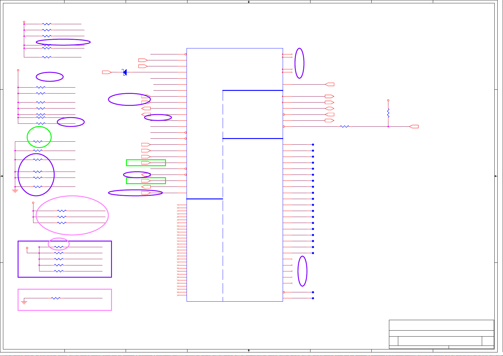
1
2
3
4
5
6
7
8
+3VALW
R966 1K_J 0402R966 1K_J 0402
1 2
R976 10K_J 0402R976 10K_J 0402
1 2
R985 10K_J 0402R985 10K_J 0402
1 2
R977 10K_J 0402R977 10K_J 0402
1 2
R964 10K_J 0402R964 10K_J 0402
A A
+3VRUN
B B
C C
D D
1 2
R983 10K_J 0402R983 10K_J 0402
1 2
R961 10K_J 0402R961 10K_J 0402
1 2
R981 10K_J 0402R981 10K_J 0402
1 2
R1627 10K_J 0402R1627 10K_J 0402
1 2
R978 10K_J 0402R978 10K_J 0402
1 2
R532 NC_10K_J 0402R532 NC_10K_J 0402
1 2
R578 10K_J 0402R578 10K_J 0402
1 2
R980 10K_J 0402R980 10K_J 0402
1 2
NC_10K_J
NC_10K_J
R979
1 2
R924 10K_J 0402R924 10K_J 0402
1 2
1 2
R943 10K_J 0402R943 10K_J 0402
1 2
R982 NC_10K_J 0402R982 NC_10K_J 0402
1 2
R974 NC_10K_J 0402R974 NC_10K_J 0402
1 2
R1626 10K_J 0402R1626 10K_J 0402
+3VRUN
+3VRUN
0402R979
0402
R6004 10K_J 0402R6004 10K_J 0402
R6005 10K_J 0402R6005 10K_J 0402
R6006 10K_J 0402R6006 10K_J 0402
R5931 NC_100K_J 0402R5931 NC_100K_J 0402
R5866 100K_J 0402R5866 100K_J 0402
R5932 100K_J 0402R5932 100K_J 0402
R5933 100K_J 0402R5933 100K_J 0402
R5934 100K_J 0402R5934 100K_J 0402
R5939 10K_J 0402R5939 10K_J 0402
1 2
EVT
1 2
1 2
1 2
1 2
1 2
GPIO28
GPIO12
RST_GATE
GPIO45
GPIO8
DVT
BMBUSY#
EXTSMI#
STP_PCI#
H_RCIN#
H_A20GATE
DIS_FAN_MON#
GPIO8
INV_EN
MB_FLASH0_EN
DVT
GPIO27
GPIO28
SATACLKREQ#
1 2
1 2
1 2
PVT
GPIO15
DVT
RUNTIME_SCI#39
DVT
ID_LPC_PCI#
RUNTIME_SCI#_D
CRIT_TEMP_REP#
LCDID4
LCDID3
LCDID2
LCDID1
LCDID0
LCDID4
DVT
DVT
2 1
D12
D12
SD103AWS
SD103AWS
DVT
EVT
CRIT_TEMP_REP#39
ID_LPC_PCI#42
SYSTEM_ID039
SYSTEM_ID139
MB_FLASH0_EN10
EVT
DIS_FAN_MON#35
U69F
U69F
BMBUSY#
EXTSMI#39
null
null
INV_EN36
DVT
LCDID035
LCDID135
LCDID235
LCDID335
RST_GATE4
LCDID435
EXTSMI#
ID_LPC_PCI#
RUNTIME_SCI#_D
GPIO8
GPIO12
GPIO15
SYSTEM_ID0
SYSTEM_ID1
MB_FLASH0_EN
INV_ENSATACLKREQ#
GPIO27
GPIO28
STP_PCI#
SATACLKREQ#
LCDID0
LCDID1
LCDID2
LCDID3
GPIO45
RST_GATE
LCDID4
CRIT_TEMP_REP#
DVT
Y3
BMBUSY# / GPIO0
C38
TACH1 / GPIO1
D37
TACH2 / GPIO6
J32
TACH3 / GPIO7
F10
GPIO8
K9
LAN_PHY_PWR_CTRL / GPIO12
T7
GPIO15
AA2
SATA4GP / GPIO16
F38
TACH0 / GPIO17
Y7
SCLOCK / GPIO22
H10
MEM_LED / GPIO24
AB12
GPIO27
V13
GPIO28
M11
STP_PCI# / GPIO34
V6
SATACLKREQ# / GPIO35
AB7
SATA2GP / GPIO36
AB13
SATA3GP / GPIO37
V3
SLOAD / GPIO38
P3
SDATAOUT0 / GPIO39
H3
PCIECLKRQ6# / GPIO45
F1
PCIECLKRQ7# / GPIO46
AB6
SDATAOUT1 / GPIO48
AA4
SATA5GP / GPIO49
F8
GPIO57
A4
VSS_NCTF_1
A49
VSS_NCTF_2
A5
VSS_NCTF_3
A50
VSS_NCTF_4
A52
VSS_NCTF_5
A53
VSS_NCTF_6
B2
VSS_NCTF_7
B4
VSS_NCTF_8
B52
VSS_NCTF_9
B53
VSS_NCTF_10
BE1
VSS_NCTF_11
BE53
VSS_NCTF_12
BF1
VSS_NCTF_13
BF53
VSS_NCTF_14
BH1
VSS_NCTF_15
BH2
VSS_NCTF_16
BH52
VSS_NCTF_17
BH53
VSS_NCTF_18
BJ1
VSS_NCTF_19
BJ2
VSS_NCTF_20
BJ4
VSS_NCTF_21
BJ49
VSS_NCTF_22
BJ5
VSS_NCTF_23
BJ50
VSS_NCTF_24
BJ52
VSS_NCTF_25
BJ53
VSS_NCTF_26
D1
VSS_NCTF_27
D2
VSS_NCTF_28
D53
VSS_NCTF_29
E1
VSS_NCTF_30
E53
VSS_NCTF_31
Ibexpeak-M
Ibexpeak-M
null
null
MISC
MISC
CLKOUT_BCLK0_N / CLKOUT_PCIE8N
CLKOUT_BCLK0_P / CLKOUT_PCIE8P
GPIO
GPIO
CPU
CPU
NCTF
NCTF
RSVD
RSVD
CLKOUT_PCIE6N
CLKOUT_PCIE6P
CLKOUT_PCIE7N
CLKOUT_PCIE7P
PROCPWRGD
THRMTRIP#
A20GATE
PECI
RCIN#
TP1
TP2
TP3
TP4
TP5
TP6
TP7
TP8
TP9
TP10
TP11
TP12
TP13
TP14
TP15
TP16
TP17
TP18
TP19
NC_1
NC_2
NC_3
NC_4
NC_5
INIT3_3V#
TP24
AH45
AH46
AF48
AF47
H_A20GATE
U2
CLK_PCH_CPU_CLK#
AM3
CLK_PCH_CPU_CLK
AM1
H_PECI
BG10
H_RCIN#
T1
H_CPUPWRGD
BE10
BD10
BA22
AW22
BB22
AY45
AY46
AV43
AV45
AF13
M18
N18
AJ24
AK41
AK42
M32
N32
M30
N30
H12
AA23
AB45
AB38
AB42
AB41
T39
P6
C10
DVT
1
1
1
1
1
1
1
1
1
1
1
1
1
1
1
1
1
1
1
DVT
1
1
R293 56_J 0402R293 56_J 0402
20MIL
20MIL
TP395
TP395
20MIL
20MIL
TP396
TP396
20MIL
20MIL
TP398
TP398
20MIL
20MIL
TP397
TP397
20MIL
20MIL
TP402
TP402
20MIL
20MIL
TP399
TP399
20MIL
20MIL
TP401
TP401
20MIL
20MIL
TP400
TP400
20MIL
20MIL
TP410
TP410
20MIL
20MIL
TP403
TP403
20MIL
20MIL
TP405
TP405
20MIL
20MIL
TP404
TP404
20MIL
20MIL
TP408
TP408
20MIL
20MIL
TP407
TP407
20MIL
20MIL
TP409
TP409
20MIL
20MIL
TP406
TP406
20MIL
20MIL
TP418
TP418
20MIL
20MIL
TP411
TP411
20MIL
20MIL
TP413
TP413
20MIL
20MIL
TP420
TP420
20MIL
20MIL
TP419
TP419
H_A20GATE 39
CLK_PCH_CPU_CLK# 4
CLK_PCH_CPU_CLK 4
H_PECI 4
H_RCIN# 39
H_CPUPWRGD 4
1 2
+1_05V_VTT
12
R291
R291
56_J
56_J
0402
0402
PM_THRMTRIP# 4,39
PVT
HON HAI Precision Ind. Co., Ltd.
HON HAI Precision Ind. Co., Ltd.
HON HAI Precision Ind. Co., Ltd.
CCPBG - R&D Division
CCPBG - R&D Division
FOXCONN
FOXCONN
FOXCONN
Title
Title
Title
PCH (GPIO,VSS_NCTF,RSVD)
PCH (GPIO,VSS_NCTF,RSVD)
PCH (GPIO,VSS_NCTF,RSVD)
Size Document Number Rev
Size Document Number Rev
Size Document Number Rev
A3
A3
A3
M960&M970 H Model SA
M960&M970 H Model SA
M960&M970 H Model SA
Date: Sheet
Date: Sheet
1
2
3
4
5
6
Date: Sheet
7
CCPBG - R&D Division
15 86Tuesday, December 29, 2009
15 86Tuesday, December 29, 2009
15 86Tuesday, December 29, 2009
8
of
of
of
Page 16

5
Default is use Internal VRM
For Disable Arrandale Graphic
GPIO27 floating as Internal VRM and there is no need external supply
D D
+1_05V_VTT
C C
+1_05V_VTT +1.05V_VCCA_CLK
DVT
+1_05V_VTT
320mA
L78
L78
NC_10UH_0805
NC_10UH_0805
EBLS2012-100K
EBLS2012-100K
1 2
NC_0_J 0603
NC_0_J 0603
R1660
R1660
12
C975
C975
NC_10U_6.3V_Y
NC_10U_6.3V_Y
0805_Y5V
0805_Y5V
R1661
R1661
0_J
0_J
0603
0603
1.85A
R1631 0_J 0603R1631 0_J 0603
1 2
12
C5246
C5246
22P_50V_J
22P_50V_J
0402_NPO
0402_NPO
12
C268
C268
22U_6.3V_M_B
22U_6.3V_M_B
0805
0805
12
C267
C267
22U_6.3V_M_B
22U_6.3V_M_B
0805
0805
For RF Noise
+VCCRTCEXT
C667
C667
0.1U_10V_K
0.1U_10V_K
0402_X5R
0402_X5R
1 2
3.062A (VCCIO)
+1_05V_VTT +1_05VRUN_SSCVCC
B B
R823 0_J 0805R823 0_J 0805
12
12
C5247
C5247
22P_50V_J
22P_50V_J
0402_NPO
0402_NPO
For RF Noise
12
C621
C621
1U_6.3V_Y
1U_6.3V_Y
0402_Y5V
0402_Y5V
C666
C666
0.1U_10V_K
0.1U_10V_K
0402_X5R
0402_X5R
1 2
163mA
+3VRUN
357mA
+1_05V_VTT
1mA
R1610 0_J 0603R1610 0_J 0603
1 2
A A
C136
C136
4.7U_6.3V_K
4.7U_6.3V_K
1 2
0603_X5R
0603_X5R
1 2
VCCRTC
2mA
5
12
12
1 2
TP_PCH_VCCDSW
C674
C674
0.1U_10V_K
0.1U_10V_K
0402_X5R
0402_X5R
1 2
VCCME
12
12
196mA
68mA
69mA
12
+3VALW
1 2
C663
C663
0.1U_10V_K
0.1U_10V_K
0402_X5R
0402_X5R
V_CPU_IO
C698
C698
0.1U_10V_K
0.1U_10V_K
0402_X5R
0402_X5R
1 2
C673
C673
0.1U_10V_K
0.1U_10V_K
0402_X5R
0402_X5R
1 2
4
C894
C894
NC_1U_6.3V_Y
NC_1U_6.3V_Y
0402_Y5V
0402_Y5V
VCCLAN
C626
C626
NC_1U_6.3V_Y
NC_1U_6.3V_Y
0402_Y5V
0402_Y5V
C624
C624
1U_6.3V_Y
1U_6.3V_Y
0402_Y5V
0402_Y5V
C661
C661
1U_6.3V_Y
1U_6.3V_Y
0402_Y5V
0402_Y5V
+1_05V_5V_8V_RUN
+1_05VRUN_DPLLA
+1_05VRUN_DPLLB
C622
C622
1U_6.3V_Y
1U_6.3V_Y
0402_Y5V
0402_Y5V
12
C664
C664
0.1U_10V_K
0.1U_10V_K
0402_X5R
0402_X5R
1 2
C665
C665
0.1U_10V_K
0.1U_10V_K
0402_X5R
0402_X5R
1 2
1 2
4
C623
C623
1U_6.3V_Y
1U_6.3V_Y
0402_Y5V
0402_Y5V
C691
C691
0.1U_10V_K
0.1U_10V_K
0402_X5R
0402_X5R
C672
C672
0.1U_10V_K
0.1U_10V_K
0402_X5R
0402_X5R
AP51
AP53
AF23
AF24
AD38
AD39
AD41
AF43
AF41
AF42
AU24
BB51
BB53
BD51
BD53
AH23
AJ35
AH35
AF34
AH34
AF32
AT18
AU18
Y20
V39
V41
V42
Y39
Y41
Y42
V9
V12
Y22
P18
U19
U20
U22
V15
V16
Y16
A12
U69J
U69J
VCCACLK[1]
VCCACLK[2]
VCCLAN[1]
VCCLAN[2]
DCPSUSBYP
VCCME[1]
VCCME[2]
VCCME[3]
VCCME[4]
VCCME[5]
VCCME[6]
VCCME[7]
VCCME[8]
VCCME[9]
VCCME[10]
VCCME[11]
VCCME[12]
DCPRTC
VCCVRM[3]
VCCADPLLA[1]
VCCADPLLA[2]
VCCADPLLB[1]
VCCADPLLB[2]
VCCIO[21]
VCCIO[22]
VCCIO[23]
VCCIO[2]
VCCIO[3]
VCCIO[4]
DCPSST
DCPSUS
VCCSUS3_3[29]
VCCSUS3_3[30]
VCCSUS3_3[31]
VCCSUS3_3[32]
VCC3_3[5]
VCC3_3[6]
VCC3_3[7]
V_CPU_IO[1]
V_CPU_IO[2]
VCCRTC
Ibexpeak-M
Ibexpeak-M
null
null
3
POWER
POWER
VCCSUS3_3[1]
VCCSUS3_3[2]
VCCSUS3_3[3]
VCCSUS3_3[4]
VCCSUS3_3[5]
VCCSUS3_3[6]
VCCSUS3_3[7]
VCCSUS3_3[8]
VCCSUS3_3[9]
VCCSUS3_3[10]
VCCSUS3_3[11]
VCCSUS3_3[12]
VCCSUS3_3[13]
USB
USB
VCCSUS3_3[14]
VCCSUS3_3[15]
VCCSUS3_3[16]
VCCSUS3_3[17]
VCCSUS3_3[18]
VCCSUS3_3[19]
VCCSUS3_3[20]
VCCSUS3_3[21]
VCCSUS3_3[22]
VCCSUS3_3[23]
VCCSUS3_3[24]
VCCSUS3_3[25]
VCCSUS3_3[26]
VCCSUS3_3[27]
VCCSUS3_3[28]
Clock and Miscellaneous
Clock and Miscellaneous
PCI/GPIO/LPC
PCI/GPIO/LPC
VCCSATAPLL[1]
VCCSATAPLL[2]
SATA
SATA
PCI/GPIO/LPC
PCI/GPIO/LPC
CPU
CPU
RTC
RTC
HDA
HDA
VCCIO[5]
VCCIO[6]
VCCIO[7]
VCCIO[8]
VCCIO[56]
V5REF_SUS
V5REF
VCC3_3[8]
VCC3_3[9]
VCC3_3[10]
VCC3_3[11]
VCC3_3[12]
VCC3_3[13]
VCC3_3[14]
VCCIO[9]
VCCVRM[4]
VCCIO[10]
VCCIO[11]
VCCIO[12]
VCCIO[13]
VCCIO[14]
VCCIO[15]
VCCIO[16]
VCCIO[17]
VCCIO[18]
VCCIO[19]
VCCIO[20]
VCCME[13]
VCCME[14]
VCCME[15]
VCCME[16]
VCCSUSHDA
V24
V26
Y24
Y26
V28
U28
U26
U24
P28
P26
N28
N26
M28
M26
L28
L26
J28
J26
H28
H26
G28
G26
F28
F26
E28
E26
C28
C26
B27
A28
A26
U23
V23
F24
K49
J38
L38
M36
N36
P36
U35
AD13
AK3
AK1
AH22
AT20
AH19
AD20
AF22
AD19
AF20
AF19
AH20
AB19
AB20
AB22
AD22
AA34
Y34
Y35
AA35
L30
3
+1_05V_VTT
12
C618
C618
1U_6.3V_Y
1U_6.3V_Y
0402_Y5V
0402_Y5V
+3VALW
12
C146
C146
0.1U_10V_K
0.1U_10V_K
0402_X5R
0402_X5R
+3VALW
12
C145
C145
0.1U_10V_K
0.1U_10V_K
0402_X5R
0402_X5R
+1_05V_VTT
+3VRUN
12
C143
C143
0.1U_10V_K
0.1U_10V_K
0402_X5R
0402_X5R
+1.05V_VCCAPLL
12
C976
C976
NC_10U_6.3V_Y
NC_10U_6.3V_Y
0805_Y5V
0805_Y5V
+VCCPLLVRM
R893 0_J 0402R893 0_J 0402
1 2
R894 0_J 0402R894 0_J 0402
1 2
R895 0_J 0402R895 0_J 0402
1 2
R896 0_J 0402R896 0_J 0402
1 2
3A (VCCIO)
163mA
163mA
3A (VCCIO)
357mA
+3VRUN
12
12
C737
C737
NC_1U_6.3V_Y
NC_1U_6.3V_Y
0402_Y5V
0402_Y5V
+1_05V_5V_8V_RUN
R826
R826
12
0_J 0603
0_J 0603
+1_05V_VTT
2
+1_05V_VTT
L28
L28
10UH_0805
10UH_0805
EBLS2012-100K
EBLS2012-100K
L63
L63
10UH_0805
10UH_0805
EBLS2012-100K
EBLS2012-100K
+3VALW
null
null
SD103AWS
SD103AWS
D4
D4
2 1
R366
R366
12
12
100_F 0402
100_F 0402
C141
C141
1U_6.3V_Y
1U_6.3V_Y
0402_Y5V
0402_Y5V
EVT
357mA
C144
C144
0.1U_10V_K
0.1U_10V_K
0402_X5R
0402_X5R
L29
L29
NC_10UH_0805
NC_10UH_0805
EBLS2012-100K
EBLS2012-100K
+1.05V_VCC_SATA
12
C731
C731
1U_6.3V_Y
1U_6.3V_Y
0402_Y5V
0402_Y5V
R825
R825
0_J
0_J
0603
0603
+1_05V_VTT
12
1.85A
+VCCSUSHDA +3VALW
12
C658
C658
1U_6.3V_Y
1U_6.3V_Y
0402_Y5V
0402_Y5V
6mA
R86
R86
0_J
0_J
0603
0603
2
+5VALW
1mA
+3VRUN
C619
C619
1U_6.3V_Y
1U_6.3V_Y
0402_Y5V
0402_Y5V
3A (VCCIO)
12
1
+1_05VRUN_DPLLA
12
+1_05VRUN_DPLLB
12
D14
D14
SD103AWS
SD103AWS
null
null
2 1
12
100_F 0402
100_F 0402
C474
C474
1U_6.3V_Y_Y
1U_6.3V_Y_Y
0402
0402
C494
C494
1U_6.3V_Y_Y
1U_6.3V_Y_Y
0402
0402
R325
R325
12
12
1mA
+5VRUN
R455
R455
NC_0_J
NC_0_J
0603
0603
12
R224
R224
NC_NV_0_J
NC_NV_0_J
0402
0402
12
R488
R488
NC_NV_0_J
NC_NV_0_J
0402
0402
EVT
+3VRUN
31mA
+1_05V_VTT
12
C6326
C6326
NC_680P_50V_K
NC_680P_50V_K
0603_X7R
0603_X7R
12
C6327
C6327
NC_680P_50V_K
NC_680P_50V_K
0603_X7R
0603_X7R
DVT
For EMI
HON HAI Precision Ind. Co., Ltd.
HON HAI Precision Ind. Co., Ltd.
HON HAI Precision Ind. Co., Ltd.
CCPBG - R&D Division
CCPBG - R&D Division
FOXCONN
FOXCONN
FOXCONN
Title
Title
Title
PCH (POWER) 1/2
PCH (POWER) 1/2
PCH (POWER) 1/2
Size Document Number Rev
Size Document Number Rev
Size Document Number Rev
Custom
Custom
Custom
M960&M970 H Model SA
M960&M970 H Model SA
M960&M970 H Model SA
Date: Sheet
Date: Sheet
Date: Sheet
CCPBG - R&D Division
1
12
16 86Thursday, December 24, 2009
16 86Thursday, December 24, 2009
16 86Thursday, December 24, 2009
C6328
C6328
NC_680P_50V_K
NC_680P_50V_K
0603_X7R
0603_X7R
DVT
of
of
of
Page 17

5
4
3
2
1
R944
R944
1 2
0_J
0_J
0603
0603
R408
R408
1 2
NC_0_J
NC_0_J
0603
0603
12
C984
C984
NC_0.1U_10V_K
NC_0.1U_10V_K
0402_X7R
0402_X7R
+3VRUN+VCCA_DAC
+3VRUN_LDO
5
4
70mA
R414
R414
1 2
NC_0_J
NC_0_J
0603
0603
R415
R415
1 2
NC_0_J
NC_0_J
0603
0603
R416
R416
1 2
0_J
0_J
0603
0603
12
C983
C983
NC_1U_10V_K
NC_1U_10V_K
0402_X5R
0402_X5R
+1_5VRUN
+1_8VRUN
L64
D D
For RF Noise
12
C5248
C5248
22P_50V_J
22P_50V_J
0402_NPO
0402_NPO
Default is use Internal VRM
For Disable Arrandale Graphic
GPIO27 floating as Internal VRM and there is no need external supply
+1_05V_VTT +1.05V_VCCPLL_EXP
C C
3.062A (VCCIO)
+1_05V_VTT
R1449
R1449
1 2
1206
1206
For RF Noise
0_J
0_J
12
C5249
C5249
22P_50V_J
22P_50V_J
0402_NPO
0402_NPO
12
C980
C980
10U_6.3V_Y
10U_6.3V_Y
0805_Y5V
0805_Y5V
DVT
12
C636
C636
1U_6.3V_Y
1U_6.3V_Y
0402_Y5V
0402_Y5V
TSC
B B
37mA
+1_05V_VTT +VCCFDIPLL +1_05V_5V_8V_RUN
L75
L75
NC_1UH_0805
NC_1UH_0805
EFLS2012-1R0M RDC15
EFLS2012-1R0M RDC15
12
C981
C981
NC_10U_6.3V_Y
NC_10U_6.3V_Y
0805_Y5V
0805_Y5V
DVT
Default is use Internal VRM
For Disable Arrandale Graphic
GPIO27 floating as Internal VRM and there is no need external supply
A A
+1_05V_VTT
12
C978
C978
10U_6.3V_Y
TSC
10U_6.3V_Y
0805_Y5V
0805_Y5V
3.062A (VCCIO)
L71
L71
NC_1UH_0805
NC_1UH_0805
EFLS2012-1R0M RDC15
EFLS2012-1R0M RDC15
12
C635
C635
1U_6.3V_Y
1U_6.3V_Y
0402_Y5V
0402_Y5V
200mA
1.5A
12
C634
C634
1U_6.3V_Y
1U_6.3V_Y
0402_Y5V
0402_Y5V
+3VRUN
1 2
R426
R426
1 2
0_J 0603
0_J 0603
12
C632
C632
1U_6.3V_Y
1U_6.3V_Y
0402_Y5V
0402_Y5V
12
C979
C979
NC_10U_6.3V_Y
NC_10U_6.3V_Y
0805_Y5V
0805_Y5V
+1.05V_VCC_EXP
12
C633
C633
1U_6.3V_Y
1U_6.3V_Y
0402_Y5V
0402_Y5V
357mA
C671
C671
0.1U_10V_K
0.1U_10V_K
0402_X5R
0402_X5R
+1_05V_VTT
+1_05V_VTT
AB24
AB26
AB28
AD26
AD28
AF26
AF28
AF30
AF31
AH26
AH28
AH30
AH31
AJ30
AJ31
AK24
BJ24
AN20
AN22
AN23
AN24
AN26
AN28
BJ26
BJ28
AT26
AT28
AU26
AU28
AV26
AV28
AW26
AW28
BA26
BA28
BB26
BB28
BC26
BC28
BD26
BD28
BE26
BE28
BG26
BG28
BH27
AN30
AN31
AN35
AT22
BJ18
AM23
U69G
U69G
VCCCORE[1]
VCCCORE[2]
VCCCORE[3]
VCCCORE[4]
VCCCORE[5]
VCCCORE[6]
VCCCORE[7]
VCCCORE[8]
VCCCORE[9]
VCCCORE[10]
VCCCORE[11]
VCCCORE[12]
VCCCORE[13]
VCCCORE[14]
VCCCORE[15]
VCCIO[24]
VCCAPLLEXP
VCCIO[25]
VCCIO[26]
VCCIO[27]
VCCIO[28]
VCCIO[29]
VCCIO[30]
VCCIO[31]
VCCIO[32]
VCCIO[33]
VCCIO[34]
VCCIO[35]
VCCIO[36]
VCCIO[37]
VCCIO[38]
VCCIO[39]
VCCIO[40]
VCCIO[41]
VCCIO[42]
VCCIO[43]
VCCIO[44]
VCCIO[45]
VCCIO[46]
VCCIO[47]
VCCIO[48]
VCCIO[49]
VCCIO[50]
VCCIO[51]
VCCIO[52]
VCCIO[53]
VCCIO[54]
VCCIO[55]
VCC3_3[1]
VCCVRM[1]
VCCFDIPLL
VCCIO[1]
Ibexpeak-M
Ibexpeak-M
null
null
POWER
POWER
VCC CORE
VCC CORE
DMI
DMI
PCI E*
PCI E*
NAND / SPI
NAND / SPI
FDI
FDI
CRTLVDS
CRTLVDS
VCCTX_LVDS[1]
VCCTX_LVDS[2]
VCCTX_LVDS[3]
VCCTX_LVDS[4]
HVCMOS
HVCMOS
VCCPNAND[1]
VCCPNAND[2]
VCCPNAND[3]
VCCPNAND[4]
VCCPNAND[5]
VCCPNAND[6]
VCCPNAND[7]
VCCPNAND[8]
VCCPNAND[9]
VCCADAC[1]
VCCADAC[2]
VSSA_DAC[1]
VSSA_DAC[2]
VCCALVDS
VSSA_LVDS
VCC3_3[2]
VCC3_3[3]
VCC3_3[4]
VCCVRM[2]
VCCDMI[1]
VCCDMI[2]
VCCME3_3[1]
VCCME3_3[2]
VCCME3_3[3]
VCCME3_3[4]
AE50
AE52
AF53
AF51
AH38
AH39
AP43
AP45
AT46
AT45
AB34
AB35
AD35
AT24
AT16
AU16
AM16
AK16
AK20
AK19
AK15
AK13
AM12
AM13
AM15
AM8
AM9
AP11
AP9
0.1U_10V_K
0.1U_10V_K
0402_X5R
0402_X5R
+VCCVRM
0.1U_10V_K
0.1U_10V_K
0402_X5R
0402_X5R
VCCME3_3
VCCALVDS, VCCTX_LVDS to GND
VSSA_LVDS NC
For disable LVDS
+3VRUN
357mA
C115
C115
1 2
R423
R423
1 2
0_J
0_J
0603
0603
12
C637
C637
1U_6.3V_Y
1U_6.3V_Y
0402_Y5V
0402_Y5V
+VCCPNAND
C114
C114
1 2
R1630 0_J 0603R1630 0_J 0603
1 2
C113
C113
0.1U_10V_K
0.1U_10V_K
0402_X5R
0402_X5R
1 2
12
C977
C977
10U_6.3V_Y
10U_6.3V_Y
0805_Y5V
0805_Y5V
+1_05V_5V_8V_RUN +1_05V_5V_8V_RUN +1_05V_VTT
R1617
R1617
NC_4.7K_J
NC_4.7K_J
0402
0402
200mA
+VCCDMI +1_05V_VTT
R417
R417
1 2
0_J
0_J
0603
0603
+3VRUN
R422
R422
1 2
+1_8VRUN
NC_0_J
NC_0_J
0603
0603
R421
R421
1 2
0_J
0_J
0603
0603
+3VRUN
+3VRUN
12
R407
NC_0_J
NC_0_J
0402
0402
61mA
156mA
0.085A
+5VRUN +3VRUN_LDO
12
C982
C982
NC_1U_10V_K
NC_1U_10V_K
0402_X5R
0402_X5R
12
1
2
L64
180R-100MHZ_0603
180R-100MHZ_0603
TI160808U181
TI160808U181R407
U65
U65
VIN
VOUT
GND
SHDN#3NC
NC_G909-330T1U
NC_G909-330T1U
HON HAI Precision Ind. Co., Ltd.
HON HAI Precision Ind. Co., Ltd.
FOXCONN
FOXCONN
FOXCONN
Title
Title
Title
PCH (POWER) 2/2
PCH (POWER) 2/2
PCH (POWER) 2/2
Size Document Number Rev
Size Document Number Rev
Size Document Number Rev
A3
A3
A3
M960&M970 H Model SA
M960&M970 H Model SA
M960&M970 H Model SA
Date: Sheet of
Date: Sheet
5
4
3
2
Date: Sheet
HON HAI Precision Ind. Co., Ltd.
CCPBG - R&D Division
CCPBG - R&D Division
CCPBG - R&D Division
of
of
17 86Thursday, December 24, 2009
17 86Thursday, December 24, 2009
1
17 86Thursday, December 24, 2009
Page 18

1
A A
B B
C C
D D
1
AY7
B11
B15
B19
B23
B31
B35
B39
B43
B47
BG12
BB12
BB16
BB20
BB24
BB30
BB34
BB38
BB42
BB49
BB5
BC10
BC14
BC18
BC2
BC22
BC32
BC36
BC40
BC44
BC52
BH9
BD48
BD49
BD5
BE12
BE16
BE20
BE24
BE30
BE34
BE38
BE42
BE46
BE48
BE50
BE6
BE8
BF3
BF49
BF51
BG18
BG24
BG4
BG50
BH11
BH15
BH19
BH23
BH31
BH35
BH39
BH43
BH47
BH7
C12
C50
D51
E12
E16
E20
E24
E30
E34
E38
E42
E46
E48
F49
G10
G14
G18
G22
G32
G36
G40
G44
G52
AF39
H16
H20
H30
H34
H38
H42
B7
E6
E8
F5
G2
2
U69I
U69I
VSS[159]
VSS[160]
VSS[161]
VSS[162]
VSS[163]
VSS[164]
VSS[165]
VSS[166]
VSS[167]
VSS[168]
VSS[169]
VSS[170]
VSS[171]
VSS[172]
VSS[173]
VSS[174]
VSS[175]
VSS[176]
VSS[177]
VSS[178]
VSS[179]
VSS[180]
VSS[181]
VSS[182]
VSS[183]
VSS[184]
VSS[185]
VSS[186]
VSS[187]
VSS[188]
VSS[189]
VSS[190]
VSS[191]
VSS[192]
VSS[193]
VSS[194]
VSS[195]
VSS[196]
VSS[197]
VSS[198]
VSS[199]
VSS[200]
VSS[201]
VSS[202]
VSS[203]
VSS[204]
VSS[205]
VSS[206]
VSS[207]
VSS[208]
VSS[209]
VSS[210]
VSS[211]
VSS[212]
VSS[213]
VSS[214]
VSS[215]
VSS[216]
VSS[217]
VSS[218]
VSS[219]
VSS[220]
VSS[221]
VSS[222]
VSS[223]
VSS[224]
VSS[225]
VSS[226]
VSS[227]
VSS[228]
VSS[229]
VSS[230]
VSS[231]
VSS[232]
VSS[233]
VSS[234]
VSS[235]
VSS[236]
VSS[237]
VSS[238]
VSS[239]
VSS[240]
VSS[241]
VSS[242]
VSS[243]
VSS[244]
VSS[245]
VSS[246]
VSS[247]
VSS[248]
VSS[249]
VSS[250]
VSS[251]
VSS[252]
VSS[253]
VSS[254]
VSS[255]
VSS[256]
VSS[257]
VSS[258]
Ibexpeak-M
Ibexpeak-M
null
null
2
3
VSS[259]
VSS[260]
VSS[261]
VSS[262]
VSS[263]
VSS[264]
VSS[265]
VSS[266]
VSS[267]
VSS[268]
VSS[269]
VSS[270]
VSS[271]
VSS[272]
VSS[273]
VSS[274]
VSS[275]
VSS[276]
VSS[277]
VSS[278]
VSS[279]
VSS[280]
VSS[281]
VSS[282]
VSS[283]
VSS[284]
VSS[285]
VSS[286]
VSS[287]
VSS[288]
VSS[289]
VSS[290]
VSS[291]
VSS[292]
VSS[293]
VSS[294]
VSS[295]
VSS[296]
VSS[297]
VSS[298]
VSS[299]
VSS[300]
VSS[301]
VSS[302]
VSS[303]
VSS[304]
VSS[305]
VSS[306]
VSS[307]
VSS[308]
VSS[309]
VSS[310]
VSS[311]
VSS[312]
VSS[313]
VSS[314]
VSS[315]
VSS[316]
VSS[317]
VSS[318]
VSS[319]
VSS[320]
VSS[321]
VSS[322]
VSS[323]
VSS[324]
VSS[325]
VSS[326]
VSS[327]
VSS[328]
VSS[329]
VSS[330]
VSS[331]
VSS[332]
VSS[333]
VSS[334]
VSS[335]
VSS[336]
VSS[337]
VSS[338]
VSS[339]
VSS[340]
VSS[341]
VSS[342]
VSS[343]
VSS[344]
VSS[345]
VSS[346]
VSS[347]
VSS[348]
VSS[349]
VSS[350]
VSS[351]
VSS[352]
VSS[353]
VSS[354]
VSS[355]
VSS[356]
VSS[366]
3
H49
H5
J24
K11
K43
K47
K7
L14
L18
L2
L22
L32
L36
L40
L52
M12
M16
M20
N38
M34
M38
M42
M46
M49
M5
M8
N24
P11
AD15
P22
P30
P32
P34
P42
P45
P47
R2
R52
T12
T41
T46
T49
T5
T8
U30
U31
U32
U34
P38
V11
P16
V19
V20
V22
V30
V31
V32
V34
V35
V38
V43
V45
V46
V47
V49
V5
V7
V8
W2
W52
Y11
Y12
Y15
Y19
Y23
Y28
Y30
Y31
Y32
Y38
Y43
Y46
P49
Y5
Y6
Y8
P24
T43
AD51
AT8
AD47
Y47
AT12
AM6
AT13
AM5
AK45
AK39
AV14
4
4
5
U69H
U69H
AB16
VSS[0]
AA19
VSS[1]
AA20
VSS[2]
AA22
VSS[3]
AM19
VSS[4]
AA24
VSS[5]
AA26
VSS[6]
AA28
VSS[7]
AA30
VSS[8]
AA31
VSS[9]
AA32
VSS[10]
AB11
VSS[11]
AB15
VSS[12]
AB23
VSS[13]
AB30
VSS[14]
AB31
VSS[15]
AB32
VSS[16]
AB39
VSS[17]
AB43
VSS[18]
AB47
VSS[19]
AB5
VSS[20]
AB8
VSS[21]
AC2
VSS[22]
AC52
VSS[23]
AD11
VSS[24]
AD12
VSS[25]
AD16
VSS[26]
AD23
VSS[27]
AD30
VSS[28]
AD31
VSS[29]
AD32
VSS[30]
AD34
VSS[31]
AU22
VSS[32]
AD42
VSS[33]
AD46
VSS[34]
AD49
VSS[35]
AD7
VSS[36]
AE2
VSS[37]
AE4
VSS[38]
AF12
VSS[39]
Y13
VSS[40]
AH49
VSS[41]
AU4
VSS[42]
AF35
VSS[43]
AP13
VSS[44]
AN34
VSS[45]
AF45
VSS[46]
AF46
VSS[47]
AF49
VSS[48]
AF5
VSS[49]
AF8
VSS[50]
AG2
VSS[51]
AG52
VSS[52]
AH11
VSS[53]
AH15
VSS[54]
AH16
VSS[55]
AH24
VSS[56]
AH32
VSS[57]
AV18
VSS[58]
AH43
VSS[59]
AH47
VSS[60]
AH7
VSS[61]
AJ19
VSS[62]
AJ2
VSS[63]
AJ20
VSS[64]
AJ22
VSS[65]
AJ23
VSS[66]
AJ26
VSS[67]
AJ28
VSS[68]
AJ32
VSS[69]
AJ34
VSS[70]
AT5
VSS[71]
AJ4
VSS[72]
AK12
VSS[73]
AM41
VSS[74]
AN19
VSS[75]
AK26
VSS[76]
AK22
VSS[77]
AK23
VSS[78]
AK28
VSS[79]
Ibexpeak-M
Ibexpeak-M
null
null
5
6
AK30
VSS[80]
AK31
VSS[81]
AK32
VSS[82]
AK34
VSS[83]
AK35
VSS[84]
AK38
VSS[85]
AK43
VSS[86]
AK46
VSS[87]
AK49
VSS[88]
AK5
VSS[89]
AK8
VSS[90]
AL2
VSS[91]
AL52
VSS[92]
AM11
VSS[93]
BB44
VSS[94]
AD24
VSS[95]
AM20
VSS[96]
AM22
VSS[97]
AM24
VSS[98]
AM26
VSS[99]
AM28
VSS[100]
BA42
VSS[101]
AM30
VSS[102]
AM31
VSS[103]
AM32
VSS[104]
AM34
VSS[105]
AM35
VSS[106]
AM38
VSS[107]
AM39
VSS[108]
AM42
VSS[109]
AU20
VSS[110]
AM46
VSS[111]
AV22
VSS[112]
AM49
VSS[113]
AM7
VSS[114]
AA50
VSS[115]
BB10
VSS[116]
AN32
VSS[117]
AN50
VSS[118]
AN52
VSS[119]
AP12
VSS[120]
AP42
VSS[121]
AP46
VSS[122]
AP49
VSS[123]
AP5
VSS[124]
AP8
VSS[125]
AR2
VSS[126]
AR52
VSS[127]
AT11
VSS[128]
BA12
VSS[129]
AH48
VSS[130]
AT32
VSS[131]
AT36
VSS[132]
AT41
VSS[133]
AT47
VSS[134]
AT7
VSS[135]
AV12
VSS[136]
AV16
VSS[137]
AV20
VSS[138]
AV24
VSS[139]
AV30
VSS[140]
AV34
VSS[141]
AV38
VSS[142]
AV42
VSS[143]
AV46
VSS[144]
AV49
VSS[145]
AV5
VSS[146]
AV8
VSS[147]
AW14
VSS[148]
AW18
VSS[149]
AW2
VSS[150]
BF9
VSS[151]
AW32
VSS[152]
AW36
VSS[153]
AW40
VSS[154]
AW52
VSS[155]
AY11
VSS[156]
AY43
VSS[157]
AY47
VSS[158]
6
7
HON HAI Precision Ind. Co., Ltd.
HON HAI Precision Ind. Co., Ltd.
HON HAI Precision Ind. Co., Ltd.
CCPBG - R&D Division
CCPBG - R&D Division
FOXCONN
FOXCONN
FOXCONN
Title
Title
Title
PCH (VSS)
PCH (VSS)
PCH (VSS)
Size Document Number Rev
Size Document Number Rev
Size Document Number Rev
A3
A3
A3
M960&M970 H Model SA
M960&M970 H Model SA
M960&M970 H Model SA
Date: Sheet
Date: Sheet
Date: Sheet
7
CCPBG - R&D Division
8
of
of
of
18 86Thursday, December 24, 2009
18 86Thursday, December 24, 2009
18 86Thursday, December 24, 2009
8
Page 19

1
2
3
4
5
6
7
8
IMVP_PWRGD_PWM78
+3VRUN
VDD_CLK_IO+1_05V_VTT+3V_CLK+3VRUN
1
2 3
RP79
RP79
0404_4P2R
0404_4P2R
0
0
12
C396
C396
10U_6.3V_M
10U_6.3V_M
0805_X5R
0805_X5R
4
12
C384
C384
0.1U_6.3V_K
0.1U_6.3V_K
0402_X5R
0402_X5R
CLK_CPU_BCLK 4
CLK_CPU_BCLK# 4
CLK_PCH_BCLK 11
CLK_PCH_BCLK# 11
R1585 NC_0_J 0402R1585 NC_0_J 0402
12
C382
C382
0.1U_6.3V_K
0.1U_6.3V_K
0402_X5R
0402_X5R
12
R1448
R1448
100K_J
100K_J
0402
0402
12
C391
C391
0.1U_6.3V_K
0.1U_6.3V_K
0402_X5R
0402_X5R
0.1U_16V_Y
0.1U_16V_Y
0402_Y5V
0402_Y5V
CLK_PWRGD
12
C498
C498
+3VALW
12
1
VCC
VCC
NC
NC
GND
GND
53
24
U40
U40
74AHC1G14GW
74AHC1G14GW
CLK_EN# 78
L37
L37
A A
R587 0_J 0402R587 0_J 0402
1 2
Y5
Y5
ITTI_L5030-14.31818-20
ITTI_L5030-14.31818-20
14.318MHZ_20P_30PPM
14.318MHZ_20P_30PPM
1 2
12
C742
C742
33P_50V_J
33P_50V_J
0402_NPO
B B
C C
0402_NPO
120R-100MHZ_0402
120R-100MHZ_0402
EBMS100505H121RDC35
EBMS100505H121RDC35
U123_XTALOUT
12
R580
R580
NC_10M_J
NC_10M_J
0402
0402
U123_XTALIN
12
C736
C736
33P_50V_J
33P_50V_J
0402_NPO
0402_NPO
DREFCLK11
DREFCLK#11
12
C414
C414
10U_6.3V_M
10U_6.3V_M
0805_X5R
0805_X5R
4
RP9
RP9
0404_4P2R
0404_4P2R
12
C410
C410
0.1U_6.3V_K
0.1U_6.3V_K
0402_X5R
0402_X5R
0
0
23
1
CLK_PCIE_SATA11
CLK_PCIE_SATA#11
CLK_DMI_PCH11
CLK_DMI_PCH#11
12
C381
C381
0.1U_6.3V_K
0.1U_6.3V_K
0402_X5R
0402_X5R
12
SMBUS Address:D2H
+3V_CLK
1
DOT96_OR_SRC0
DOT96#_OR_SRC0#
R_DREFSSCLK_OR_27M
R_DREFSSCLK#_OR_27M_S
2
3
4
5
6
7
8
RP84 0 0404_4P2RRP84 0 0404_4P2R
RP85 0 0404_4P2RRP85 0 0404_4P2R
C411
C411
0.1U_6.3V_K
0.1U_6.3V_K
0402_X5R
0402_X5R
VDD_DOT
VSS_DOT
DOT96
DOT96#
VDD_27
27_NSS
27_SS
VSS_27
1
2 3
1
2 3
12
C408
C408
0.1U_6.3V_K
0.1U_6.3V_K
0402_X5R
0402_X5R
REF0
30
31
32
33
29
SCLK
SDATA
REF0/FS
THERMALPAD
VSS_SATA9SRC0/SATA10SRC0#/SATA#11VSS_SRC12SRC113SRC1#14VDD_SRC_IO15CPU_STP#
CLK_PCIE_SATA_R
CLK_PCIE_SATA#_R
4
4
12
C390
C390
0.1U_6.3V_K
0.1U_6.3V_K
0402_X5R
0402_X5R
SMB_CLK_R 11,20,21,43
SMB_DATA_R 11,20,21,43
R571 33_F0402 R571 33_F0402
12
R563 10K_J0402 R563 10K_J0402
12
U123_XTALIN
U123_XTALOUT
CLK_PWRGD
27
26
25
28
XTAL_IN
VDD_CPU
VSS_REF
VDD_REF
XTAL_OUT
CPU0
CPU#0
CKPWRGD/PD#
VSS_CPU
CPU1
CPU#1
VDD_CPU_IO
VDD_SRC
SL28748CLC
SL28748CLC
16
null
null
STP_CPU#
CLK_DMI_PCH_R
CLK_DMI_PCH#_R
CPU_BSEL2
U31
U31
24
23
22
21
20
19
18
17
L35
L35
120R-100MHZ_0402
120R-100MHZ_0402
EBMS100505H121RDC35
EBMS100505H121RDC35
REF_14M_PCH 11
+3V_CLK
CLK_CPU_BCLK
CLK_CPU_BCLK#
CLK_PCH_BCLK_R
CLK_PCH_BCLK#_R
EVT
VDD_CLK_IO
R594 10K_J0402 R594 10K_J0402
STP_CPU#
12
Frequency Select Pin (FS)
CPU Power On SRC SATA DOT96 27MHz
FS
Default01133MHz
100MHz
D D
1
2
REF
14.318MHz27MHz96MHz100MHz100MHz
CPU_BSEL2
3
+1_05V_VTT
12
R560
R560
NC_1K_J
NC_1K_J
0402
0402
12
R1269
R1269
0_J
0_J
0402
0402
H:100 MHz
L:133 MHz
4
R_DREFSSCLK#_OR_27M_S
R_DREFSSCLK_OR_27M
09/11/17 R_XTALSSIN be Connect a stable clock source
(from clock gen SS 27MHz) to GPIO26_TCK.
RP86 0 0404_4P2RRP86 0 0404_4P2R
1
4
2 3
5
R_XTALSSIN 24
R_XTALIN 24
6
HON HAI Precision Ind. Co., Ltd.
HON HAI Precision Ind. Co., Ltd.
FOXCONN
FOXCONN
FOXCONN
Title
Title
Title
CLOCK GEN
CLOCK GEN
CLOCK GEN
Size Document Number Rev
Size Document Number Rev
Size Document Number Rev
A3
A3
A3
M960&M970 H Model SA
M960&M970 H Model SA
M960&M970 H Model SA
Date: Sheet
Date: Sheet
Date: Sheet
7
HON HAI Precision Ind. Co., Ltd.
CCPBG - R&D Division
CCPBG - R&D Division
CCPBG - R&D Division
of
of
of
19 86Tuesday, December 29, 2009
19 86Tuesday, December 29, 2009
19 86Tuesday, December 29, 2009
8
Page 20
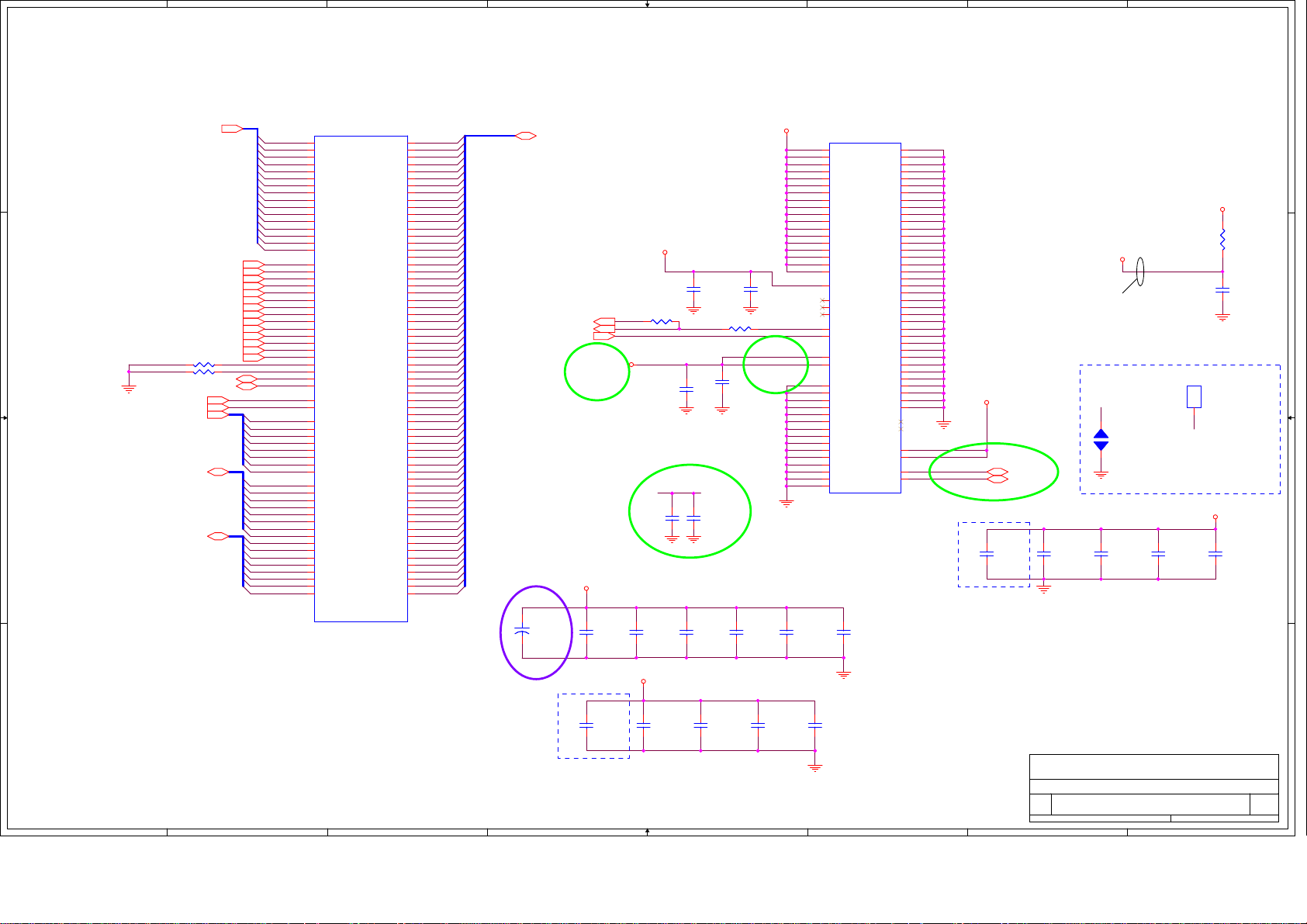
1
2
3
4
5
6
7
8
A A
M_A_A[15:0]5
M_A_BS05
M_A_BS15
M_A_BS25
M_CS#05
M_CS#15
M_CLK_DDR05
M_CLK_DDR#05
B B
C C
M_CLK_DDR15
M_CLK_DDR#15
M_CKE05
M_CKE15
M_A_CAS#5
M_A_RAS#5
M_A_WE#5
R61 10K_J 0402R61 10K_J 0402
R58 10K_J 0402R58 10K_J 0402
M_A_DM[7:0]5
M_A_DQS[7:0]5
M_A_DQS#[7:0]5
12
12
SMB_CLK_R11,19,21,43
SMB_DATA_R11,19,21,43
M_ODT05
M_ODT15
M_A_DM0
M_A_DM1
M_A_DM2
M_A_DM3
M_A_DM4
M_A_DM5
M_A_DM6
M_A_DM7
M_A_DQS0
M_A_DQS1
M_A_DQS2
M_A_DQS3
M_A_DQS4
M_A_DQS5
M_A_DQS6
M_A_DQS7
M_A_DQS#0
M_A_DQS#1
M_A_DQS#2
M_A_DQS#3
M_A_DQS#4
M_A_DQS#5
M_A_DQS#6
M_A_DQS#7
CN34A
CN34A
M_A_A0
98
A0
M_A_A1
97
A1
M_A_A2
96
A2
M_A_A3
95
A3
M_A_A4
92
A4
M_A_A5
91
A5
M_A_A6
90
A6
M_A_A7
86
A7
M_A_A8
89
A8
M_A_A9
85
A9
M_A_A10
107
A10/AP
M_A_A11
84
A11
M_A_A12
83
A12/BC#
M_A_A13
119
A13
M_A_A14
80
A14
M_A_A15
78
A15
109
BA0
108
BA1
79
BA2
114
S0#
121
S1#
101
CK0
103
CK0#
102
CK1
104
CK1#
73
CKE0
74
CKE1
115
CAS#
110
RAS#
113
SA0_DIM0
SA1_DIM0
WE#
197
SA0
201
SA1
202
SCL
200
SDA
116
ODT0
120
ODT1
11
DM0
28
DM1
46
DM2
63
DM3
136
DM4
153
DM5
170
DM6
187
DM7
12
DQS0
29
DQS1
47
DQS2
64
DQS3
137
DQS4
154
DQS5
171
DQS6
188
DQS7
10
DQS#0
27
DQS#1
45
DQS#2
62
DQS#3
135
DQS#4
152
DQS#5
169
DQS#6
186
DQS#7
SOCKET_2x102P
SOCKET_2x102P
FOX_AS0A626-N2SN-7H
FOX_AS0A626-N2SN-7H
SMBus Address: A0H(W)/A1H(R)
DQ10
DQ11
DQ12
DQ13
DQ14
DQ15
DQ16
DQ17
DQ18
DQ19
DQ20
DQ21
DQ22
DQ23
DQ24
DQ25
DQ26
DQ27
DQ28
DQ29
DQ30
DQ31
DQ32
DQ33
DQ34
DQ35
DQ36
DQ37
DQ38
DQ39
DQ40
DQ41
DQ42
DQ43
DQ44
DQ45
DQ46
DQ47
DQ48
DQ49
DQ50
DQ51
DQ52
DQ53
DQ54
DQ55
DQ56
DQ57
DQ58
DQ59
DQ60
DQ61
DQ62
DQ63
DQ0
DQ1
DQ2
DQ3
DQ4
DQ5
DQ6
DQ7
DQ8
DQ9
5
7
15
17
4
6
16
18
21
23
33
35
22
24
34
36
39
41
51
53
40
42
50
52
57
59
67
69
56
58
68
70
129
131
141
143
130
132
140
142
147
149
157
159
146
148
158
160
163
165
175
177
164
166
174
176
181
183
191
193
180
182
192
194
M_A_DQ1
M_A_DQ0
M_A_DQ3
M_A_DQ2
M_A_DQ5
M_A_DQ4
M_A_DQ7
M_A_DQ6
M_A_DQ8
M_A_DQ9
M_A_DQ10
M_A_DQ11
M_A_DQ13
M_A_DQ12
M_A_DQ15
M_A_DQ14
M_A_DQ16
M_A_DQ17
M_A_DQ18
M_A_DQ19
M_A_DQ21
M_A_DQ20
M_A_DQ22
M_A_DQ23
M_A_DQ25
M_A_DQ24
M_A_DQ31
M_A_DQ30
M_A_DQ28
M_A_DQ29
M_A_DQ27
M_A_DQ26
M_A_DQ36
M_A_DQ37
M_A_DQ35
M_A_DQ34
M_A_DQ32
M_A_DQ33
M_A_DQ38
M_A_DQ39
M_A_DQ45
M_A_DQ44
M_A_DQ43
M_A_DQ42
M_A_DQ41
M_A_DQ40
M_A_DQ46
M_A_DQ47
M_A_DQ52
M_A_DQ49
M_A_DQ54
M_A_DQ55
M_A_DQ48
M_A_DQ53
M_A_DQ51
M_A_DQ50
M_A_DQ61
M_A_DQ60
M_A_DQ62
M_A_DQ63
M_A_DQ56
M_A_DQ57
M_A_DQ59
M_A_DQ58
M_A_DQ[63:0] 5
PM_EXTTS#14,21
PM_EXTTS#04
DDR3_DRAMRST#4,21
12
CAP13
CAP13
NC_330U_2.5V_K
NC_330U_2.5V_K
+
+
3.5x2.8x1.9
3.5x2.8x1.9
DVT
+1_5VSUS
12
R1291 NC_0_J 0402R1291 NC_0_J 0402
DDR3_VREF
EVT
C1152
C1152
10U_10V_M
10U_10V_M
0805_X5R
0805_X5R
+3VRUN
2.2U_10V_Y
2.2U_10V_Y
1 2
2.2U_10V_Y
2.2U_10V_Y
2.2U_10V_Y
2.2U_10V_Y
0603
0603
12
C949
C949
10U_10V_M
10U_10V_M
0805_X5R
0805_X5R
+1_5VSUS
12
C32
C32
0603
0603
R1275 NC_0_J 0402R1275 NC_0_J 0402
12
C40
C40
0603
0603
DDR3_VREF
12
12
C35
C35
12
C950
C950
10U_10V_M
10U_10V_M
0805_X5R
0805_X5R
0.1U_16V_Y
0.1U_16V_Y
0402_Y5V
0402_Y5V
1 2
EVT
12
C41
C41
0.1U_16V_Y
0.1U_16V_Y
0402_Y5V
0402_Y5V
EVT
12
C31
C31
C36
C36
0.1U_16V_Y
0.1U_16V_Y
0402_Y5V
0402_Y5V
12
C951
C951
10U_10V_M
10U_10V_M
0805_X5R
0805_X5R
+1_5VSUS
TS#_DIMM0
12
C952
C952
10U_10V_M
10U_10V_M
0805_X5R
0805_X5R
CN34B
CN34B
75
VDD1
76
VDD2
81
VDD3
82
VDD4
87
VDD5
88
VDD6
93
VDD7
94
VDD8
99
VDD9
100
VDD10
105
VDD11
106
VDD12
111
VDD13
112
VDD14
117
VDD15
118
VDD16
123
VDD17
124
VDD18
199
VDDSPD
77
NC1
122
NC2
125
NCTEST
198
EVENT#
30
RESET#
1
VREF_DQ
126
VREF_CA
2
VSS1
3
VSS2
8
VSS3
9
VSS4
13
VSS5
14
VSS6
19
VSS7
20
VSS8
25
VSS9
26
VSS10
31
VSS11
32
VSS12
37
VSS13
38
VSS14
43
VSS15
SOCKET_2x102P
SOCKET_2x102P
FOX_AS0A626-N2SN-7H
FOX_AS0A626-N2SN-7H
12
C953
C953
10U_10V_M
10U_10V_M
0805_X5R
0805_X5R
VSS16
VSS17
VSS18
VSS19
VSS20
VSS21
VSS22
VSS23
VSS24
VSS25
VSS26
VSS27
VSS28
VSS29
VSS30
VSS31
VSS32
VSS33
VSS34
VSS35
VSS36
VSS37
VSS38
VSS39
VSS40
VSS41
VSS42
VSS43
VSS44
VSS45
VSS46
VSS47
VSS48
VSS49
VSS50
VSS51
VSS52
NPTH1
NPTH2
VTT1
VTT2
44
48
49
54
55
60
61
65
66
71
72
127
128
133
134
138
139
144
145
150
151
155
156
161
162
167
168
172
173
178
179
184
185
189
190
195
196
205
206
203
204
207
G1
208
G2
EMCS2
+0_75VRUN
EMCS2 21
EMCS1 21
DDR3_VREF
(20 mil)
EMCS2
21
J2
J2
OPEN_JUMP_OPEN2
OPEN_JUMP_OPEN2
DDRDIMM_VREF
For EMC
SPR2
SPR2
NC_SPRING_6x2.5
NC_SPRING_6x2.5
null
null
1
1
EMCS1
12
R296
R296
0_J
0_J
0402
0402
C269
C269
0.1U_16V_M
0.1U_16V_M
0402
0402
1 2
EVT
12
C5250
C5250
22P_50V_J
22P_50V_J
0402_NPO
0402_NPO
For RF Noise
Place these Caps near So-DIMM0
12
C945
C945
1U_10V_K
1U_10V_K
0402_X5R
0402_X5R
12
C946
C946
1U_10V_K
1U_10V_K
0402_X5R
0402_X5R
12
C947
C947
1U_10V_K
1U_10V_K
0402_X5R
0402_X5R
+0_75VRUN
12
C948
C948
1U_10V_K
1U_10V_K
0402_X5R
0402_X5R
12
C5251
C5251
22P_50V_J
D D
22P_50V_J
0402_NPO
0402_NPO
12
C956
C956
0.1U_10V_K
0.1U_10V_K
0402_X5R
0402_X5R
For RF Noise
1
2
3
4
12
C957
C957
0.1U_10V_K
0.1U_10V_K
0402_X5R
0402_X5R
12
C958
C958
0.1U_10V_K
0.1U_10V_K
0402_X5R
0402_X5R
5
12
C959
C959
0.1U_10V_K
0.1U_10V_K
0402_X5R
0402_X5R
HON HAI Precision Ind. Co., Ltd.
HON HAI Precision Ind. Co., Ltd.
HON HAI Precision Ind. Co., Ltd.
CCPBG - R&D Division
CCPBG - R&D Division
FOXCONN
FOXCONN
FOXCONN
Title
Title
Title
DDRIII(SO-DIMM_0) 1/2
DDRIII(SO-DIMM_0) 1/2
DDRIII(SO-DIMM_0) 1/2
Size Document Number Rev
Size Document Number Rev
Size Document Number Rev
Custom
Custom
Custom
M960&M970 H Model SA
M960&M970 H Model SA
M960&M970 H Model SA
Date: Sheet
Date: Sheet of
6
Date: Sheet of
7
CCPBG - R&D Division
20 86Tuesday, December 29, 2009
20 86Tuesday, December 29, 2009
20 86Tuesday, December 29, 2009
8
of
Page 21

1
A A
M_B_A[15:0]5
B B
R77 10K_J 0402R77 10K_J 0402
+3VRUN
C C
R78 10K_J 0402R78 10K_J 0402
SMB_DATA_R11,19,20,43
M_ODT25
M_ODT35
M_B_DM[7:0]5
M_B_DQS[7:0]5
M_B_DQS#[7:0]5
2
CN35A
CN35A
M_B_A0
98
A0
M_B_A1
97
A1
M_B_A2
96
A2
M_B_A3
95
A3
M_B_A4
92
A4
M_B_A5
91
A5
M_B_A6
90
A6
M_B_A7
86
A7
M_B_A8
89
A8
M_B_A9
85
A9
M_B_A10
107
A10/AP
M_B_A11
84
A11
M_B_A12
83
A12/BC#
M_B_A13
119
A13
M_B_A14
80
A14
M_B_A15
78
A15
SA0_DIM1
SA1_DIM1
M_B_DM0
M_B_DM1
M_B_DM2
M_B_DM3
M_B_DM4
M_B_DM5
M_B_DM6
M_B_DM7
M_B_DQS0
M_B_DQS1
M_B_DQS2
M_B_DQS3
M_B_DQS4
M_B_DQS5
M_B_DQS6
M_B_DQS7
M_B_DQS#0
M_B_DQS#1
M_B_DQS#2
M_B_DQS#3
M_B_DQS#4
M_B_DQS#5
M_B_DQS#6
M_B_DQS#7
109
BA0
108
BA1
79
BA2
114
S0#
121
S1#
101
CK0
103
CK0#
102
CK1
104
CK1#
73
CKE0
74
CKE1
115
CAS#
110
RAS#
113
WE#
197
SA0
201
SA1
202
SCL
200
SDA
116
ODT0
120
ODT1
11
DM0
28
DM1
46
DM2
63
DM3
136
DM4
153
DM5
170
DM6
187
DM7
12
DQS0
29
DQS1
47
DQS2
64
DQS3
137
DQS4
154
DQS5
171
DQS6
188
DQS7
10
DQS#0
27
DQS#1
45
DQS#2
62
DQS#3
135
DQS#4
152
DQS#5
169
DQS#6
186
DQS#7
SOCKET_2x102P
SOCKET_2x102P
FOX_AS0A626-JASG-7H
FOX_AS0A626-JASG-7H
M_B_BS05
M_B_BS15
M_B_BS25
M_CS#25
M_CS#35
M_CLK_DDR25
M_CLK_DDR#25
M_CLK_DDR35
M_CLK_DDR#35
M_CKE25
M_CKE35
M_B_CAS#5
M_B_RAS#5
M_B_WE#5
12
12
SMB_CLK_R11,19,20,43
DQ0
DQ1
DQ2
DQ3
DQ4
DQ5
DQ6
DQ7
DQ8
DQ9
DQ10
DQ11
DQ12
DQ13
DQ14
DQ15
DQ16
DQ17
DQ18
DQ19
DQ20
DQ21
DQ22
DQ23
DQ24
DQ25
DQ26
DQ27
DQ28
DQ29
DQ30
DQ31
DQ32
DQ33
DQ34
DQ35
DQ36
DQ37
DQ38
DQ39
DQ40
DQ41
DQ42
DQ43
DQ44
DQ45
DQ46
DQ47
DQ48
DQ49
DQ50
DQ51
DQ52
DQ53
DQ54
DQ55
DQ56
DQ57
DQ58
DQ59
DQ60
DQ61
DQ62
DQ63
3
M_B_DQ1
5
M_B_DQ0
7
M_B_DQ3
15
M_B_DQ2
17
M_B_DQ5
4
M_B_DQ4
6
M_B_DQ7
16
M_B_DQ6
18
M_B_DQ8
21
M_B_DQ9
23
M_B_DQ10
33
M_B_DQ11
35
M_B_DQ13
22
M_B_DQ12
24
M_B_DQ15
34
M_B_DQ14
36
M_B_DQ16
39
M_B_DQ17
41
M_B_DQ18
51
M_B_DQ19
53
M_B_DQ21
40
M_B_DQ20
42
M_B_DQ22
50
M_B_DQ23
52
M_B_DQ25
57
M_B_DQ24
59
M_B_DQ31
67
M_B_DQ30
69
M_B_DQ28
56
M_B_DQ29
58
M_B_DQ27
68
M_B_DQ26
70
M_B_DQ36
129
M_B_DQ37
131
M_B_DQ35
141
M_B_DQ34
143
M_B_DQ32
130
M_B_DQ33
132
M_B_DQ38
140
M_B_DQ39
142
M_B_DQ45
147
M_B_DQ44
149
M_B_DQ43
157
M_B_DQ42
159
M_B_DQ40
146
M_B_DQ41
148
M_B_DQ47
158
M_B_DQ46
160
M_B_DQ49
163
M_B_DQ48
165
M_B_DQ54
175
M_B_DQ55
177
M_B_DQ52
164
M_B_DQ53
166
M_B_DQ51
174
M_B_DQ50
176
M_B_DQ61
181
M_B_DQ60
183
M_B_DQ63
191
M_B_DQ62
193
M_B_DQ56
180
M_B_DQ57
182
M_B_DQ58
192
M_B_DQ59
194
+1_5VSUS
12
C1151
C1151
10U_10V_M
10U_10V_M
0805_X5R
0805_X5R
4
M_B_DQ[63:0] 5
DDR3_DRAMRST#4,20
12
C960
C960
10U_10V_M
10U_10V_M
0805_X5R
0805_X5R
PM_EXTTS#14,20
DDR3_VREF
12
+3VRUN
2.2U_10V_Y
2.2U_10V_Y
2.2U_10V_Y
2.2U_10V_Y
C961
C961
10U_10V_M
10U_10V_M
0805_X5R
0805_X5R
12
C33
C33
2.2U_10V_Y
2.2U_10V_Y
0603
0603
R1276 NC_0_J 0402R1276 NC_0_J 0402
1 2
12
C43
C43
0603
0603
12
12
C44
C44
C37
C37
0.1U_16V_Y
12
C962
C962
10U_10V_M
10U_10V_M
0805_X5R
0805_X5R
0.1U_16V_Y
0402_Y5V
0402_Y5V
12
0603
0603
5
12
C34
C34
0.1U_16V_Y
0.1U_16V_Y
0402_Y5V
0402_Y5V
EVT
12
C38
C38
0.1U_16V_Y
0.1U_16V_Y
0402_Y5V
0402_Y5V
EVT
C963
C963
10U_10V_M
10U_10V_M
0805_X5R
0805_X5R
+1_5VSUS
TS#_DIMM1
12
C964
C964
10U_10V_M
10U_10V_M
0805_X5R
0805_X5R
CN35B
CN35B
75
VDD1
76
VDD2
81
VDD3
82
VDD4
87
VDD5
88
VDD6
93
VDD7
94
VDD8
99
VDD9
100
VDD10
105
VDD11
106
VDD12
111
VDD13
112
VDD14
117
VDD15
118
VDD16
123
VDD17
124
VDD18
199
VDDSPD
77
NC1
122
NC2
125
NCTEST
198
EVENT#
30
RESET#
1
VREF_DQ
126
VREF_CA
2
VSS1
3
VSS2
8
VSS3
9
VSS4
13
VSS5
14
VSS6
19
VSS7
20
VSS8
25
VSS9
26
VSS10
31
VSS11
32
VSS12
37
VSS13
38
VSS14
43
VSS15
SOCKET_2x102P
SOCKET_2x102P
FOX_AS0A626-JASG-7H
FOX_AS0A626-JASG-7H
12
CAP22
CAP22
+
+
NC_330U_2.5V_K
NC_330U_2.5V_K
3.5x2.8x1.9
3.5x2.8x1.9
VSS16
VSS17
VSS18
VSS19
VSS20
VSS21
VSS22
VSS23
VSS24
VSS25
VSS26
VSS27
VSS28
VSS29
VSS30
VSS31
VSS32
VSS33
VSS34
VSS35
VSS36
VSS37
VSS38
VSS39
VSS40
VSS41
VSS42
VSS43
VSS44
VSS45
VSS46
VSS47
VSS48
VSS49
VSS50
VSS51
VSS52
NPTH1
NPTH2
VTT1
VTT2
6
44
48
49
54
55
60
61
65
66
71
72
127
128
133
134
138
139
144
145
150
151
155
156
161
162
167
168
172
173
178
179
184
185
189
190
195
196
207
208
203
204
G1
G1
G2
G2
+0_75VRUN
EMCS1
EMCS2DDR3_VREF
7
EMCS1 20
EMCS2 20
8
EVT
12
C5253
C5253
22P_50V_J
22P_50V_J
0402_NPO
0402_NPO
For RF Noise
Place these Caps near So-DIMM1
12
C971
C971
1U_10V_K
1U_10V_K
0402_X5R
0402_X5R
12
C972
C972
1U_10V_K
1U_10V_K
0402_X5R
0402_X5R
12
C973
C973
1U_10V_K
1U_10V_K
0402_X5R
0402_X5R
+0_75VRUN
12
C974
C974
1U_10V_K
1U_10V_K
0402_X5R
0402_X5R
DVT
+1_5VSUS
D D
12
C5252
C5252
22P_50V_J
22P_50V_J
0402_NPO
0402_NPO
For RF Noise
1
2
3
12
C967
C967
0.1U_10V_K
0.1U_10V_K
0402_X5R
0402_X5R
4
12
C968
C968
0.1U_10V_K
0.1U_10V_K
0402_X5R
0402_X5R
12
C969
C969
0.1U_10V_K
0.1U_10V_K
0402_X5R
0402_X5R
5
12
C970
C970
0.1U_10V_K
0.1U_10V_K
0402_X5R
0402_X5R
HON HAI Precision Ind. Co., Ltd.
HON HAI Precision Ind. Co., Ltd.
HON HAI Precision Ind. Co., Ltd.
CCPBG - R&D Division
CCPBG - R&D Division
FOXCONN
FOXCONN
FOXCONN
Title
Title
Title
DDRIII(SO-DIMM_1) 2/2
DDRIII(SO-DIMM_1) 2/2
DDRIII(SO-DIMM_1) 2/2
Size Document Number Rev
Size Document Number Rev
Size Document Number Rev
Custom
Custom
Custom
M960&M970 H Model SA
M960&M970 H Model SA
M960&M970 H Model SA
Date: Sheet
Date: Sheet of
6
Date: Sheet of
7
CCPBG - R&D Division
21 86Tuesday, December 29, 2009
21 86Tuesday, December 29, 2009
21 86Tuesday, December 29, 2009
8
of
Page 22
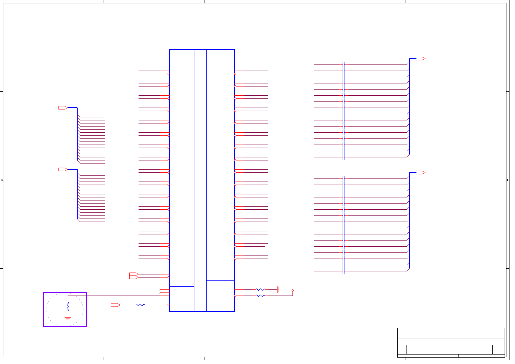
5
D D
PEG_RXP_C[0..15]3
PEG_RXP_C0
PEG_RXP_C1
PEG_RXP_C2
PEG_RXP_C3
PEG_RXP_C4
PEG_RXP_C5
12
PEG_RXP_C6
PEG_RXP_C7
PEG_RXP_C8
PEG_RXP_C9
PEG_RXP_C10
PEG_RXP_C11
PEG_RXP_C12
PEG_RXP_C13
PEG_RXP_C14
PEG_RXP_C15
PEG_RXN_C0
PEG_RXN_C1
PEG_RXN_C2
PEG_RXN_C3
PEG_RXN_C4
PEG_RXN_C5
PEG_RXN_C6
PEG_RXN_C7
PEG_RXN_C8
PEG_RXN_C9
PEG_RXN_C10
PEG_RXN_C11
PEG_RXN_C12
PEG_RXN_C13
PEG_RXN_C14
PEG_RXN_C15
PLT_RST#14,42,44,45,50
PCIE_REFCLK11
PCIE_REFCLK#11
R5762 0_J 0402R5762 0_J 0402
1 2
C C
PEG_RXN_C[0..15]3
B B
DVT
A A
0402
0402
10K_J
10K_J
R5831
R5831
4
PEG_RXP_C0
PEG_RXN_C0
PEG_RXP_C1
PEG_RXN_C1
PEG_RXP_C2
PEG_RXN_C2
PEG_RXP_C3
PEG_RXN_C3
PEG_RXP_C4
PEG_RXN_C4
PEG_RXP_C5
PEG_RXN_C5
PEG_RXP_C6
PEG_RXN_C6
PEG_RXP_C7
PEG_RXN_C7
PEG_RXP_C8
PEG_RXN_C8
PEG_RXP_C9
PEG_RXN_C9
PEG_RXP_C10
PEG_RXN_C10
PEG_RXP_C11
PEG_RXN_C11
PEG_RXP_C12
PEG_RXN_C12
PEG_RXP_C13
PEG_RXN_C13
PEG_RXP_C14
PEG_RXN_C14
PEG_RXP_C15
PEG_RXN_C15
AA38
Y37
Y35
W36
W38
V37
V35
U36
U38
T37
T35
R36
R38
P37
P35
N36
N38
M37
M35
K37
K35
H37
H35
G36
G38
F37
F35
E37
AB35
AA36
AJ21
AK21
AH16
AA30
L36
L38
J36
J38
U204A
U204A
null
null
PCIE_RX0P
PCIE_RX0N
PCIE_RX1P
PCIE_RX1N
PCIE_RX2P
PCIE_RX2N
PCIE_RX3P
PCIE_RX3N
PCIE_RX4P
PCIE_RX4N
PCIE_RX5P
PCIE_RX5N
PCIE_RX6P
PCIE_RX6N
PCIE_RX7P
PCIE_RX7N
PCIE_RX8P
PCIE_RX8N
PCIE_RX9P
PCIE_RX9N
PCIE_RX10P
PCIE_RX10N
PCIE_RX11P
PCIE_RX11N
PCIE_RX12P
PCIE_RX12N
PCIE_RX13P
PCIE_RX13N
PCIE_RX14P
PCIE_RX14N
PCIE_RX15P
PCIE_RX15N
CLOCK
CLOCK
PCIE_REFCLKP
PCIE_REFCLKN
NC_1
NC_2
PWRGOOD
PERSTB
216-0774008
216-0774008
3
TXP0
PCIE_TX0P
PCIE_TX0N
PCIE_TX1P
PCIE_TX1N
PCIE_TX2P
PCIE_TX2N
PCIE_TX3P
PCIE_TX3N
PCIE_TX4P
PCIE_TX4N
PCIE_TX5P
PCIE_TX5N
PCIE_TX6P
PCIE_TX6N
PCIE_TX7P
PCIE_TX7N
PCIE_TX8P
PCIE_TX8N
PCIE_TX9P
PCIE_TX9N
PCIE_TX10P
PCIE_TX10N
PCIE_TX11P
PCIE_TX11N
PCIE_TX12P
PCIE_TX12N
PCIE_TX13P
PCIE_TX13N
PCIE_TX14P
PCIE_TX14N
PCIE_TX15P
PCIE_TX15N
CALIBRATION
CALIBRATION
PCIE_CALRP
PCIE_CALRN
Y33
TXN0
Y32
TXP1
W33
TXN1
W32
TXP2
U33
TXN2
U32
TXP3
U30
TXN3
U29
TXP4
T33
TXN4
T32
PCI EXPRESS INTERFACE
PCI EXPRESS INTERFACE
TXP5
T30
TXN5
T29
TXP6
P33
TXN6
P32
TXP7
P30
TXN7
P29
TXP8
N33
TXN8
N32
TXP9
N30
TXN9
N29
TXP10
L33
TXN10
L32
TXP11
L30
TXN11
L29
TXP12
K33
TXN12
K32
TXP13
J33
TXN13
J32
TXP14
K30
TXN14
K29
TXP15
H33
TXN15
H32
1 2
Y30
R5760 1.27K_F 0402R5760 1.27K_F 0402
1 2
Y29
R5761 2K_F 0402R5761 2K_F 0402
PCIE_VDDC
TXN0
TXN1
TXN2
TXN3
TXN4
TXN5
TXN6
TXN7
TXN8
TXN9
TXN10
TXN11
TXN12
TXN13
TXN14
TXN15
TXP0
TXP1
TXP2
TXP3
TXP4
TXP5
TXP6
TXP7
TXP8
TXP9
TXP10
TXP11
TXP12
TXP13
TXP14
TXP15
1 2
C319 0.1U_6.3V_K 0201_X5RC319 0.1U_6.3V_K 0201_X5R
1 2
C320 0.1U_6.3V_K 0201_X5RC320 0.1U_6.3V_K 0201_X5R
1 2
C321 0.1U_6.3V_K 0201_X5RC321 0.1U_6.3V_K 0201_X5R
1 2
C322 0.1U_6.3V_K 0201_X5RC322 0.1U_6.3V_K 0201_X5R
1 2
C323 0.1U_6.3V_K 0201_X5RC323 0.1U_6.3V_K 0201_X5R
1 2
C324 0.1U_6.3V_K 0201_X5RC324 0.1U_6.3V_K 0201_X5R
1 2
C325 0.1U_6.3V_K 0201_X5RC325 0.1U_6.3V_K 0201_X5R
1 2
C326 0.1U_6.3V_K 0201_X5RC326 0.1U_6.3V_K 0201_X5R
1 2
C327 0.1U_6.3V_K 0201_X5RC327 0.1U_6.3V_K 0201_X5R
1 2
C328 0.1U_6.3V_K 0201_X5RC328 0.1U_6.3V_K 0201_X5R
1 2
C329 0.1U_6.3V_K 0201_X5RC329 0.1U_6.3V_K 0201_X5R
1 2
C330 0.1U_6.3V_K 0201_X5RC330 0.1U_6.3V_K 0201_X5R
1 2
C331 0.1U_6.3V_K 0201_X5RC331 0.1U_6.3V_K 0201_X5R
1 2
C332 0.1U_6.3V_K 0201_X5RC332 0.1U_6.3V_K 0201_X5R
1 2
C333 0.1U_6.3V_K 0201_X5RC333 0.1U_6.3V_K 0201_X5R
1 2
C334 0.1U_6.3V_K 0201_X5RC334 0.1U_6.3V_K 0201_X5R
1 2
C301 0.1U_6.3V_K 0201_X5RC301 0.1U_6.3V_K 0201_X5R
1 2
C302 0.1U_6.3V_K 0201_X5RC302 0.1U_6.3V_K 0201_X5R
1 2
C303 0.1U_6.3V_K 0201_X5RC303 0.1U_6.3V_K 0201_X5R
1 2
C306 0.1U_6.3V_K 0201_X5RC306 0.1U_6.3V_K 0201_X5R
1 2
C307 0.1U_6.3V_K 0201_X5RC307 0.1U_6.3V_K 0201_X5R
1 2
C308 0.1U_6.3V_K 0201_X5RC308 0.1U_6.3V_K 0201_X5R
1 2
C309 0.1U_6.3V_K 0201_X5RC309 0.1U_6.3V_K 0201_X5R
1 2
C310 0.1U_6.3V_K 0201_X5RC310 0.1U_6.3V_K 0201_X5R
1 2
C311 0.1U_6.3V_K 0201_X5RC311 0.1U_6.3V_K 0201_X5R
1 2
C312 0.1U_6.3V_K 0201_X5RC312 0.1U_6.3V_K 0201_X5R
1 2
C313 0.1U_6.3V_K 0201_X5RC313 0.1U_6.3V_K 0201_X5R
1 2
C314 0.1U_6.3V_K 0201_X5RC314 0.1U_6.3V_K 0201_X5R
1 2
C315 0.1U_6.3V_K 0201_X5RC315 0.1U_6.3V_K 0201_X5R
1 2
C316 0.1U_6.3V_K 0201_X5RC316 0.1U_6.3V_K 0201_X5R
1 2
C317 0.1U_6.3V_K 0201_X5RC317 0.1U_6.3V_K 0201_X5R
1 2
C318 0.1U_6.3V_K 0201_X5RC318 0.1U_6.3V_K 0201_X5R
2
PEG_RXN0
PEG_RXN1
PEG_RXN2
PEG_RXN3
PEG_RXN4
PEG_RXN5
PEG_RXN6
PEG_RXN7
PEG_RXN8
PEG_RXN9
PEG_RXN10
PEG_RXN11
PEG_RXN12
PEG_RXN13
PEG_RXN14
PEG_RXN15
PEG_RXP0
PEG_RXP1
PEG_RXP2
PEG_RXP3
PEG_RXP4
PEG_RXP5
PEG_RXP6
PEG_RXP7
PEG_RXP8
PEG_RXP9
PEG_RXP10
PEG_RXP11
PEG_RXP12
PEG_RXP13
PEG_RXP14
PEG_RXP15
PEG_RXN[15..0] 3
PEG_RXP[15..0] 3
1
Ball AH16:
For M96 this pin NC.
For Madison-M2 and Park-M2
the PWRGOOD ball must be conneccted to ground.
For M97-M2 PWRGOOD input must be provided externally.
5
HON HAI Precision Ind. Co., Ltd.
HON HAI Precision Ind. Co., Ltd.
HON HAI Precision Ind. Co., Ltd.
CCPBG - R&D Division
CCPBG - R&D Division
FOXCONN
FOXCONN
FOXCONN
Title
Title
Title
VGA (PCI-E) 1/6
VGA (PCI-E) 1/6
VGA (PCI-E) 1/6
Size Document Number Rev
Size Document Number Rev
Size Document Number Rev
A3
A3
A3
M960&M970 H Model SA
M960&M970 H Model SA
M960&M970 H Model SA
Date: Sheet
Date: Sheet
4
3
2
Date: Sheet
CCPBG - R&D Division
22 86Tuesday, December 29, 2009
22 86Tuesday, December 29, 2009
1
22 86Tuesday, December 29, 2009
of
of
of
Page 23
5
4
3
2
1
EVT
Strap for DDR3 VRAM
ATI_DVPDATA[3 : 0]
For M960/M970 M92-M2 XTX / Park-XT
D D
0001 64Mx16 Reserve x4pcs
0010 64Mx16 Hynix * x4pcs
0011 64Mx16 Samsung** x4pcs
0101 64Mx16 Reserve x4pcs
0110 64Mx16 Elpida*** x4pcs
0111 64Mx16 AMD**** x4pcs
For M960/M970 Madsion-LP
0001 64Mx16 Reserve x8pcs
0010 64Mx16 Hynix * x8pcs
0011 64Mx16 Samsung** x8pcs
0101 64Mx16 Reserve x8pcs
0110 64Mx16 Elpida*** x8pcs
0111 64Mx16 AMD**** x8pcs
P.S. * means Hynix H5TQ1G63BFR-12C,800MHz
**means Samsung K4W1G1646E-HC12T00,800MHz
***means Elpida EDJ1116DBSE-DJ-F,1333MHz
****means AMD 23EY2387MA-12,800MHz
C C
If no ROM attached, GPIO[13:12:11]
CONFIG{2:0}
controls the memory aperture size.
64MB 010
128MB 000
256MB 001
512MB 001
EVT
CONFIGURATION STRAPS
+1_8VRUN
MEM_ID0
R5763 10K_J 0402R5763 10K_J 0402
ATI_DVPDATA024
ATI_DVPDATA124
ATI_DVPDATA224
ATI_DVPDATA324
ATI_GPIO024
ATI_GPIO524
ATI_GPIO1124
ATI_GPIO1224
ATI_GPIO1324
MEM_ID1
MEM_ID2
MEM_ID3
1 2
R5764 NC_10K_J 0402R5764 NC_10K_J 0402
1 2
R5765 NC_10K_J 0402R5765 NC_10K_J 0402
1 2
R5766 NC_10K_J 0402R5766 NC_10K_J 0402
1 2
R5769 10K_J 0402R5769 10K_J 0402
1 2
R5770 NC_10K_J 0402R5770 NC_10K_J 0402
1 2
R5771 10K_J 0402R5771 10K_J 0402
1 2
R5772 NC_10K_J 0402R5772 NC_10K_J 0402
1 2
R5773 NC_10K_J 0402R5773 NC_10K_J 0402
1 2
+3V3_DELAY
ALLOW FOR PULLUP PADS FOR THESE STRAPS AND IF THESE GPIOS ARE USED,
THEY MUST NOT CONFLICT DURING RESET
STRAPS DESCRIPTION OF DEFAULT SETTINGSPIN name
GPIO_0TX_PWRS_ENB
TX_DEEMPH_EN PCI Express Transmitter De-emphasis Enable
AC_BATT
PWRCNTL_0
PWRCNTL_1
CONFIG[0]
CONFIG[1]
CONFIG[2]
SSIN Spread Spectrum clock input for memory clock and/or engine clock (maximum
THERMAL_INT Thermal monitor interrupt Can be set as either:
GPIO_1
GPIO_5
GPIO_6
GPIO_15
GPIO_20
GPIO_21BB_EN Back Bias (BB) control:
GPIO_7BLON Controls Backlight On/Off.
GPIO_9VGA_DIS 0: VGA Controller capacity enabled
GPIO_11
GPIO_12
GPIO_13
GPIO_22BIOS_ROM_EN Enable external BIOS ROM device
GPIO_16
GPIO_17
GPIO_23CLKREQB Reserve
Transmitter Power Savings Enable
0: 50% Tx output swing
1: Full Tx output swing
0: Tx de-emphasis disabled
1: Tx de-emphasis enabled
AC (Performance mode) = 3.3 V
Battery saving mode = 0.0 V
Power Control signals control the core voltage regulator.
At Reset, these signals will be inputs with weak internal pull-down resistors.
VBIOS can define these signals to be either 3.3-V outputs or open drain outputs.
The output state (high/low) of these signals is programmable for each PowerPlay state.
When GPIO_21_BB_EN = 0 V, then back bias is disabled on the PCB (i.e. BPP = VDDC).
When GPIO_21_BB_EN = 3.3 V, then back bias is enabled on the PCB (i.e. BPP = VDDC +Offset).
Can function as a GPIO if not required for BB control.
Active high.
If not needed as the backlight enable signal, it can alternatively be used as a GPIO or an open drain type output.
Note: External pull-down recommended
1: The device will not be recognized as the system’s VGA controller
If BIOS_ROM_EN = 0, then Config[2:0] defines the primary memory aperture size.
0: Disable external BIOS ROM device
1: Enable external BIOS ROM device
down spread of -2.5%). Requires a spread version of 27 MHz(The modulation rate is 30-50 KHz.)
1) An input from an external temperature sensor (ALERTb) , or
2) An output signaling that the ASIC temp (measured by the internal sensor) is above the high
threshold or below the low threshold.Output can be open drain or 3.3-V output.(active low by default)
RECOMMENDED SETTINGS
0= DO NOT INSTALL RESISTOR
1 = INSTALL 10K RESISTOR
X = DESIGN DEPENDANT
NA = NOT APPLICABLE
B B
1 Enable HD Audio
0 Disable HD Audio
1 Enable HDMI
0 Disable HDMI
A A
5
ATI_DAC1VSYNC24,34
ATI_DAC1HSYNC24,34
R5774 10K_J 0402R5774 10K_J 0402
1 2
R108
R108
NC_10K_J
NC_10K_J
0402
0402
1 2
R116 10K_J 0402R116 10K_J 0402
1 2
R5775
R5775
NC_10K_J
NC_10K_J
0402
0402
1 2
4
HON HAI Precision Ind. Co., Ltd.
HON HAI Precision Ind. Co., Ltd.
HON HAI Precision Ind. Co., Ltd.
CCPBG - R&D Division
CCPBG - R&D Division
FOXCONN
FOXCONN
FOXCONN
Title
Title
Title
VGA (Strap) 2/6
VGA (Strap) 2/6
VGA (Strap) 2/6
Size Document Number Rev
Size Document Number Rev
Size Document Number Rev
A3
A3
A3
M960&M970 H Model SA
M960&M970 H Model SA
M960&M970 H Model SA
Date: Sheet
Date: Sheet
3
2
Date: Sheet
CCPBG - R&D Division
23 86Tuesday, December 29, 2009
23 86Tuesday, December 29, 2009
1
23 86Tuesday, December 29, 2009
of
of
of
Page 24

1
A A
EVT
MEM ID
Ball AM17:
For M96 this pin can be not used.
For M97-M2 When PWRGOOD is deasserted, the CTF
will return to its default state (high impedance)
For Park-M2 and Madison-M2:
GPIO_19_CTF has an internal latch, such
that if the pad has been operating normally,
and then the internal PWRGOOD deasserts
(because CTF was triggered), the GPIO_19 will
continue to drive high to keep the
VDDC regulator shut down.
Clearing this state will require power-cycling
of the VDDR3 rail.
B B
These two can be unused on M96,M97,Madison and Park.
Ball AH26:
For M97-M2 GENERICF (no HPD function).
For Park-M2 NC.
For Madison-M2 GENERICF- can provide HPD5 function
Ball AH24:
For M97-M2 GENERICF (no HPD function).
For Park-M2 NC.
For Madison-M2 GENERICF- can provide HPD6 function
PWRCNTL_080
R_XTALSSIN19
09/11/17 Connect a stable clock source
(from clock gen SS 27MHz)
to GPIO26_TCK.
C C
DEPENDING ON OSC USED
SELECT VOLTAGE DIVIDER
RESISTOR VALUES C AND B
TO ENSURE XTALIN VOLTAGE
LEVEL OF 1.8V
R5793
R5793
12
R6003
R6003
NC_1M_J
NC_1M_J
0402
0402
DVT
ATI_XTALIN_R
12
1
1 2
100_F
100_F
0402
0402
R6002
R6002
1 2
NC_0_J 0402
NC_0_J 0402
Y9
Y9
NC_27MHZ_20P_30PPM
NC_27MHZ_20P_30PPM
ITTI_L5030-27.000-20
ITTI_L5030-27.000-20
R_XTALIN19
PVT
C6342
C6342
12
NC_22P_50V_J
NC_22P_50V_J
0402_NPO
0402_NPO
C6343
C6343
D D
12
NC_22P_50V_J
NC_22P_50V_J
0402_NPO
0402_NPO
Reserve for Intel FCIM function
R5784 0_J 0402R5784 0_J 0402
OVT_GFX#39,58
PWRCNTL_180
TP1115 26MILTP1115 26MIL
+3V3_DELAY
R6001
R6001
R_XTALSSIN R_XTALSSIN_R
TP1107
TP1107
26MIL
26MIL
EVT
+1_8VRUN
12
R5790
R5790
499_F
499_F
0402
0402
12
R5791
R5791
249_F
249_F
0402
0402
12
R5794
R5794
120_F
120_F
0402
0402
DVT
ATI_XTALIN
ATI_XTALOUT
For M96 these two pins connect to GND.
GND Option If XO_IN/XO_IN2 not used
For M97, XO_IN and XO_IN2 should be grounded
Ball AW34:
For M97-M2 GND
For Madison-M2 and Park-M2 27MHz oscillator can be resvered.
Ball AW35:
For M97-M2 DPE_VSSR
For Madison-M2 and Park-M2 100MHz oscillator can be resvered.
2
ATI_DVPDATA023
ATI_DVPDATA123
ATI_DVPDATA223
ATI_DVPDATA323
TP1097
TP1097
TP1098
TP1098
ATI_GPIO023
SMB_THRM_DATA11,39,58
SMB_THRM_CLK11,39,58
ATI_GPIO523
ATI_INV_EN36
TP1261
TP1261
TP1099
TP1099
PVT
TP1100
TP1100
ATI_GPIO1123
ATI_GPIO1223
ATI_GPIO1323
TP1101
TP1101
R5783 NC_0_J 0402R5783 NC_0_J 0402
R5786 10K_J 0402R5786 10K_J 0402
NC_0_J 0402
NC_0_J 0402
12
1
1 2
ATI_JTAG_RST
ATI_JTAG_TDI
12
ATI_JTAG_TMS
ATI_JTAG_TDO
1
ATI_HDMI_DET_334,38
AT_VREFG
12
C6097
C6097
0.1U_6.3V_K
0.1U_6.3V_K
0402_X5R
0402_X5R
TP1108
TP1108
TP1109
TP1109
12
TP1102
TP1102
TP1103
TP1103
TP1262
TP1262
ATI_XTALIN
ATI_XTALOUT
EVT
ATI_THERMDP58
ATI_THERMDN58
TSVDD
2
EVT
26MIL
26MIL
26MIL
26MIL
26MIL
26MIL
26MIL
26MIL
26MIL
26MIL
26MIL
26MIL
ATI_GPIO23
26MIL
26MIL
26MIL
26MIL
DPLL_PVDD
DPLL_VDDC
26MIL
26MIL
26MIL
26MIL
XTALSSIN
26MIL
26MIL
1
1
AR8
AU8
AP8
AW8
AR3
AR1
AU1
AU3
AW3
AP6
AW5
AU5
AR6
AW6
AU6
AT7
AV7
AN7
AV9
AT9
AR10
AW10
AU10
AP10
AV11
AT11
AR12
AW12
AU12
AP12
AK26
1
AJ26
1
AH20
AH18
AN16
AH23
AJ23
AH17
AJ17
AK17
AJ13
1
AH15
1
AJ16
1
AK16
AL16
AM16
AM14
1
AM13
AK14
AG30
AN14
1
AM17
1
AL13
AJ14
AK13
1
AN13
AM23
AN23
AK23
AL24
AM24
AJ19
AK19
AJ20
AK20
AJ24
AH26
AH24
AK24
AH13
AM32
AN32
AN31
AV33
AU34
AW34
AW35
AF29
AG29
AK32
AL31
AJ32
AJ33
U204B
U204B
null
null
MUTI GFX
MUTI GFX
DVPCNTL_MVP_0
DVPCNTL_MVP_1
DVPCNTL_0
DVPCNTL_1
DVPCNTL_2
DVPCLK
DVPDATA_0
DVPDATA_1
DVPDATA_2
DVPDATA_3
DVPDATA_4
DVPDATA_5
DVPDATA_6
DVPDATA_7
DVPDATA_8
DVPDATA_9
DVPDATA_10
DVPDATA_11
DVPDATA_12
DVPDATA_13
DVPDATA_14
DVPDATA_15
DVPDATA_16
DVPDATA_17
DVPDATA_18
DVPDATA_19
DVPDATA_20
DVPDATA_21
DVPDATA_22
DVPDATA_23
I2C
I2C
SCL
SDA
GENERAL PURPOSE I/O
GENERAL PURPOSE I/O
GPIO_0
GPIO_1
GPIO_2
GPIO_3_SMBDATA
GPIO_4_SMBCLK
GPIO_5_AC_BATT
GPIO_6
GPIO_7_BLON
GPIO_8_ROMSO
GPIO_9_ROMSI
GPIO_10_ROMSCK
GPIO_11
GPIO_12
GPIO_13
GPIO_14_HPD2
GPIO_15_PWRCNTL_0
GPIO_16_SSIN
GPIO_17_THERMAL_INT
GPIO_18_HPD3
GPIO_19_CTF
GPIO_20_PWRCNTL_1
GPIO_21_BB_EN
GPIO_22_ROMCSB
GPIO_23_CLKREQB
JTAG_TRSTB
JTAG_TDI
JTAG_TCK
JTAG_TMS
JTAG_TDO
GENERICA
GENERICB
GENERICC
GENERICD
GENERICE_HPD4
GENERICF
GENERICG
HPD1
VREFG
DPLL_PVDD
DPLL_PVSS
PLL/CLOCK
PLL/CLOCK
DPLL_VDDC
XTALIN
XTALOUT
XO_IN
XO_IN2
DPLUS
THERMAL
THERMAL
DMINUS
TS_FDO
NC_TS_A
TSVDD
TSVSS
216-0774008
216-0774008
DPA
DPA
DPB
DPB
DPC
DPC
DPD
DPD
DAC1
DAC1
DAC2
DAC2
DDC/AUX
DDC/AUX
DDCCLK_AUX3P
DDCDATA_AUX3N
DDCCLK_AUX4P
DDCDATA_AUX4N
DDCCLK_AUX5P
DDCDATA_AUX5N
DDCCLK_AUX7P
DDCDATA_AUX7N
3
TXCAP_DPA3P
TXCAM_DPA3N
TX0P_DPA2P
TX0M_DPA2N
TX1P_DPA1P
TX1M_DPA1N
TX2P_DPA0P
TX2M_DPA0N
TXCBP_DPB3P
TXCBM_DPB3N
TX3P_DPB2P
TX3M_DPB2N
TX4P_DPB1P
TX4M_DPB1N
TX5P_DPB0P
TX5M_DPB0N
TXCCP_DPC3P
TXCCM_DPC3N
TX0P_DPC2P
TX0M_DPC2N
TX1P_DPC1P
TX1M_DPC1N
TX2P_DPC0P
TX2M_DPC0N
TXCDP_DPD3P
TXCDM_DPD3N
TX3P_DPD2P
TX3M_DPD2N
TX4P_DPD1P
TX4M_DPD1N
TX5P_DPD0P
TX5M_DPD0N
HSYNC
VSYNC
RSET
AVDD
AVSSQ
VDD1DI
VSS1DI
COMP
H2SYNC
V2SYNC
VDD2DI
VSS2DI
A2VDD
A2VDDQ
A2VSSQ
R2SET
DDC1CLK
DDC1DATA
AUX1P
AUX1N
DDC2CLK
DDC2DATA
AUX2P
AUX2N
DDC6CLK
DDC6DATA
3
4
TXCAM_DPA0P
AU24
AV23
AT25
AR24
AU26
AV25
AT27
AR26
AR30
AT29
AV31
AU30
AR32
AT31
AT33
AU32
AU14
AV13
AT15
AR14
AU16
AV15
AT17
AR16
AU20
AT19
AT21
AR20
AU22
AV21
AT23
AR22
AD39
R
AD37
RB
AE36
G
AD35
GB
AF37
B
AE38
BB
AC36
AC38
AB34
AD34
AE34
AC33
AC34
AC30
R2
AC31
R2B
AD30
G2
AD31
G2B
AF30
B2
AF31
B2B
AC32
C
AD32
Y
AF32
AD29
AC29
AG31
AG32
AG33
AD33
AF33
AA29
AM26
AN26
AM27
AL27
AM19
AL19
AN20
AM20
AL30
AM30
AL29
AM29
AN21
AM21
AJ30
AJ31
AK30
AK29
C6089 0.1U_6.3V_K0402_X5RC6089 0.1U_6.3V_K0402_X5R
TXCAM_DPA0N
TX0M_DPA0P
TX0M_DPA0N
TX0M_DPA1P
TX0M_DPA1N
TX0M_DPA2P
TX0M_DPA2N
DP_D channel is available for M97-M2,Madison-M2,M96-M2.
DP Channel D is NC on Park.
R5776 0_J 0402R5776 0_J 0402
R5777 0_J 0402R5777 0_J 0402
R5778 0_J 0402R5778 0_J 0402
ATI_DAC1HSYNC 23,34
ATI_DAC1VSYNC 23,34
499_F
499_F
1 2
R5782
AVDD
VDD1DI
1 2
C6090 0.1U_6.3V_K0402_X5RC6090 0.1U_6.3V_K0402_X5R
1 2
C6091 0.1U_6.3V_K0402_X5RC6091 0.1U_6.3V_K0402_X5R
1 2
C6092 0.1U_6.3V_K0402_X5RC6092 0.1U_6.3V_K0402_X5R
1 2
C6093 0.1U_6.3V_K0402_X5RC6093 0.1U_6.3V_K0402_X5R
1 2
C6094 0.1U_6.3V_K0402_X5RC6094 0.1U_6.3V_K0402_X5R
1 2
C6095 0.1U_6.3V_K0402_X5RC6095 0.1U_6.3V_K0402_X5R
1 2
C6096 0.1U_6.3V_K0402_X5RC6096 0.1U_6.3V_K0402_X5R
1 2
1 2
1 2
1 2
PLACE OR RESISTORS CLOSE TO ASIC
0402R5782
0402
ATI_DAC1RED 34
ATI_DAC1RED_RB 34
ATI_DAC1GREEN 34
ATI_DAC1GREEN_GB 34
ATI_DAC1BLUE 34
ATI_DAC1BLUE_BB 34
MP
EVT
VDD1DI
VDD3
A2VDDQ
1 2
R5792 715_F 0402R5792 715_F 0402
ATI_CRT_SCL 34
ATI_CRT_SDA 34
DVT
For Park-M2:
DDC/Aux Pairs 1,2,3,5,6 are available
DDC/Aux Pair 4,7 is not connected.
For M96-M2,M97-M2,Madison-M2:
DDC/Aux Pairs 1,2,3,4,5,6 are available
DDC/Aux Pair 7 is not connected.
ATI_HDMI_SCL 38
ATI_HDMI_SDA 38
4
ATI_HDMI_TXCA 38
ATI_HDMI_TXCA# 38
ATI_HDMI_D0 38
ATI_HDMI_D0# 38
ATI_HDMI_D1 38
ATI_HDMI_D1# 38
ATI_HDMI_D2 38
ATI_HDMI_D2# 38
OPTIONAL STRAP TO GROUND
FOR RB,GB,BB
SEE DAC1_RGB SHEET
5
ATI_DAC1RED
ATI_DAC1GREEN
12
R5780
R5780
150_F
150_F
0402
0402
NC_10K_J
NC_10K_J
1 2
NC_10K_J
NC_10K_J
1 2
NC_10K_J
NC_10K_J
1 2
NC_10K_J
NC_10K_J
1 2
ATI_DAC1BLUE
12
R5781
R5781
150_F
150_F
0402
0402
0402R5906
0402
0402R5907
0402
0402R5909
0402
0402R5908
0402
12
R5779
R5779
150_F
150_F
0402
0402
OPTIONAL STRAP TO GROUND
FOR R2B,G2B,B2B
SEE DAC2_RGB SHEET
IF Y,C,COMP OR R2,G2,B2 ARE USED
R2B,G2B,B2B MUST BE CONNECTED
TO GROUND OR TERMINATED AT
CONNECTOR
DAC2 CAN BE TV SIGNALS (C,Y,COMP) OR SECONDARY CRT (R2,B2,G2
SIGNALS AS CONTROLLED BY AN INTERNAL MUX
ATI_JTAG_RST
ATI_JTAG_TDI
ATI_JTAG_TMS
R_XTALSSIN
R5906
R5907
R5909
R5908
5
+3V3_DELAY
6
ATI_JTAG_RST
R5991
NC_10K_J
NC_10K_J
1 2
7
8
PVT
0402R5991
0402
EVT
09/11/17 Add 5991 pull-down with 10K ohm to ground for the Park/Madison JTAG test block
intermittently fails to initialize correctly. Incorrect initialization may
result in a failure to boot.
HON HAI Precision Ind. Co., Ltd.
HON HAI Precision Ind. Co., Ltd.
FOXCONN
FOXCONN
FOXCONN
Title
Title
Title
VGA (I/O) 3/6
VGA (I/O) 3/6
VGA (I/O) 3/6
Size Document Number Rev
Size Document Number Rev
Size Document Number Rev
A2
A2
A2
M960&M970 H Model
M960&M970 H Model
M960&M970 H Model
Date: Sheet
Date: Sheet
6
7
Date: Sheet
HON HAI Precision Ind. Co., Ltd.
CCPBG - R&D Division
CCPBG - R&D Division
CCPBG - R&D Division
8
SA
SA
SA
of
of
of
24 86Tuesday, December 29, 2009
24 86Tuesday, December 29, 2009
24 86Tuesday, December 29, 2009
Page 25
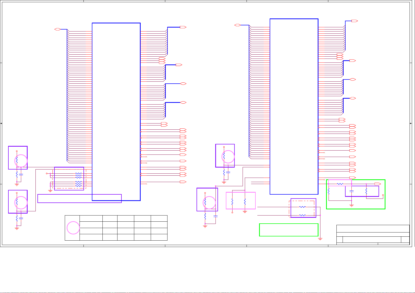
5
U204C
U204C
DDR2
DDR2
GDDR3/GDDR5
GDDR3/GDDR5
DDR3
D D
C C
FBAD[0:63]28,29
DVT
+1_5VRUN
B B
A A
PVT
R5797
R5797
100_F
100_F
0402
0402
+1_5VRUN
PVT
R5813
R5813
100_F
100_F
0402
0402
12
12
12
12
R5795
R5795
40.2_F
40.2_F
0402
0402
12
DVT
R5809
R5809
40.2_F
40.2_F
0402
0402
12
C6098
C6098
0.1U_6.3V_K
0.1U_6.3V_K
0402_X5R
0402_X5R
C6103
C6103
0.1U_6.3V_K
0.1U_6.3V_K
0402_X5R
0402_X5R
DVT
+1_5VRUN
R5798 243_F 0402R5798 243_F 0402
R5800 243_F 0402R5800 243_F 0402
R5799 243_F 0402R5799 243_F 0402
R5802 243_F 0402R5802 243_F 0402
R5803 243_F 0402R5803 243_F 0402
R5804 243_F 0402R5804 243_F 0402
Park: Stuff R5800/R5802, NC R5798/R5799/R5803/R5804
Madison: NC R5800/R5802, Stuff R5798/R5799/R5803/R5804
FBAD0
FBAD1
FBAD2
FBAD3
FBAD4
FBAD5
FBAD6
FBAD7
FBAD8
FBAD9
FBAD10
FBAD11
FBAD12
FBAD13
FBAD14
FBAD15
FBAD16
FBAD17
FBAD18
FBAD19
FBAD20
FBAD21
FBAD22
FBAD23
FBAD24
FBAD25
FBAD26
FBAD27
FBAD28
FBAD29
FBAD30
FBAD31
FBAD32
FBAD33
FBAD34
FBAD35
FBAD36
FBAD37
FBAD38
FBAD39
FBAD40
FBAD41
FBAD42
FBAD43
FBAD44
FBAD45
FBAD46
FBAD47
FBAD48
FBAD49
FBAD50
FBAD51
FBAD52
FBAD53
FBAD54
FBAD55
FBAD56
FBAD57
FBAD58
FBAD59
FBAD60
FBAD61
FBAD62
FBAD63
1 2
1 2
1 2
1 2
1 2
1 2
GPU voltage reference resistor value table
PVT
5
DDR3
C37
DQA0_0
C35
DQA0_1
A35
DQA0_2
E34
DQA0_3
G32
DQA0_4
D33
DQA0_5
F32
DQA0_6
E32
DQA0_7
D31
DQA0_8
F30
DQA0_9
C30
DQA0_10
A30
DQA0_11
F28
DQA0_12
C28
DQA0_13
A28
DQA0_14
E28
DQA0_15
D27
DQA0_16
F26
DQA0_17
C26
DQA0_18
A26
DQA0_19
F24
DQA0_20
C24
DQA0_21
A24
DQA0_22
E24
DQA0_23
C22
DQA0_24
A22
DQA0_25
F22
DQA0_26
D21
DQA0_27
A20
DQA0_28
F20
DQA0_29
D19
DQA0_30
E18
DQA0_31
C18
DQA1_0
A18
DQA1_1
F18
DQA1_2
D17
DQA1_3
A16
DQA1_4
F16
DQA1_5
D15
DQA1_6
E14
DQA1_7
F14
DQA1_8
D13
DQA1_9
F12
DQA1_10
A12
DQA1_11
D11
DQA1_12
F10
DQA1_13
A10
DQA1_14
C10
DQA1_15
G13
DQA1_16
H13
DQA1_17
J13
DQA1_18
H11
DQA1_19
G10
DQA1_20
G8
DQA1_21
K9
DQA1_22
K10
DQA1_23
G9
DQA1_24
A8
DQA1_25
C8
DQA1_26
E8
DQA1_27
A6
DQA1_28
C6
DQA1_29
E6
DQA1_30
A5
DQA1_31
L18
MVREFDA
L20
MVREFSA
L27
MEM_CALRN0
N12
MEM_CALRN1
AG12
MEM_CALRN2
M12
MEM_CALRP1
M27
MEM_CALRP0
AH12
MEM_CALRP2
216-0774008
216-0774008
GPU chip R5795
Madison-LP
Park-XT
M92 XTX
null
null
40.2
40.2
100
4
DDR2
DDR2
GDDR5/GDDR3
GDDR5/GDDR3
DDR3
DDR3
MAA0_0
MAA0_1
MAA0_2
MAA0_3
MAA0_4
MAA0_5
MAA0_6
MAA0_7
MAA1_0
MAA1_1
MAA1_2
MAA1_3
MAA1_4
MAA1_5
MAA1_6
MAA1_7
WCKA0_0
WCKA0B_0
WCKA0_1
WCKA0B_1
WCKA1_0
WCKA1B_0
WCKA1_1
WCKA1B_1
GDDR5/DDR2/GDDR3
GDDR5/DDR2/GDDR3
MEMORY INTERFACE A
MEMORY INTERFACE A
EDCA0_0
EDCA0_1
EDCA0_2
EDCA0_3
EDCA1_0
EDCA1_1
EDCA1_2
EDCA1_3
DDBIA0_0
DDBIA0_1
DDBIA0_2
DDBIA0_3
DDBIA1_0
DDBIA1_1
DDBIA1_2
DDBIA1_3
ADBIA0
ADBIA1
CLKA0
CLKA0B
CLKA1
CLKA1B
RASA0B
RASA1B
CASA0B
CASA1B
CSA0B_0
CSA0B_1
CSA1B_0
CSA1B_1
CKEA0
CKEA1
WEA0B
WEA1B
MAA0_8
MAA1_8
GDDR5
GDDR5
G24
J23
H24
J24
H26
J26
H21
G21
H19
H20
L13
G16
J16
H16
J17
H17
A32
C32
D23
E22
C14
A14
E10
D9
C34
D29
D25
E20
E16
E12
J10
D7
A34
E30
E26
C20
C16
C12
J11
F8
J21
G19
H27
G27
J14
H14
K23
K19
K20
K17
K24
K27
M13
K16
K21
J20
K26
L15
H23
J19
FBA_A0
FBA_A1
FBA_A2
FBA_A3
FBA_A4
FBA_A5
FBA_A6
FBA_A7
FBA_A8
FBA_A9
FBA_A10
FBA_A11
FBA_A12
FBA_BA2
FBA_BA0
FBA_BA1
FBADQM0
FBADQM1
FBADQM2
FBADQM3
FBADQM4
FBADQM5
FBADQM6
FBADQM7
FBARDQS0
FBARDQS1
FBARDQS2
FBARDQS3
FBARDQS4
FBARDQS5
FBARDQS6
FBARDQS7
FBAWDQS0
FBAWDQS1
FBAWDQS2
FBAWDQS3
FBAWDQS4
FBAWDQS5
FBAWDQS6
FBAWDQS7
FBA_ODTA0
FBA_ODTA1
FBA_CLK0
FBA_CLK0#
FBA_CLK1
FBA_CLK1#
FBA_RASA0#
FBA_RASA1#
FBA_CASA0#
FBA_CASA1#
FBA_CSA0_0#
FBA_CSA1_0#
FBA_CKEA0
FBA_CKEA1
FBA_WEA0#
FBA_WEA1#
FBA_A13
DVT
R5809
40.2
40.2
100
R5796 R5810
40.2
40.2
100
4
40.2
40.2
100
FBA_BA2 28,29
FBA_BA0 28,29
FBA_BA1 28,29
FBA_ODTA0 28
FBA_ODTA1 29
FBA_A[0..12] 28,29
FBADQM[0..7] 28,29
FBARDQS[7..0] 28,29
FBAWDQS[7..0] 28,29
FBA_CLK0 28
FBA_CLK0# 28
FBA_CLK1 29
FBA_CLK1# 29
FBA_RASA0# 28
FBA_RASA1# 29
FBA_CASA0# 28
FBA_CASA1# 29
FBA_CSA0_0# 28
FBA_CSA1_0# 29
FBA_CKEA0 28
FBA_CKEA1 29
FBA_WEA0# 28
FBA_WEA1# 29
FBA_A13 28,29
+1_5VRUN
PVT
R5814
R5814
100_F
100_F
0402
0402
3
12
12
3
DVT
R5810
R5810
40.2_F
40.2_F
0402
0402
+1_5VRUN
PVT
R5801
R5801
100_F
100_F
0402
0402
12
C6104
C6104
0.1U_6.3V_K
0.1U_6.3V_K
0402_X5R
0402_X5R
FBCD[63..0]30,31
DVT
12
R5796
R5796
40.2_F
40.2_F
0402
0402
12
12
C6099
C6099
0.1U_6.3V_K
0.1U_6.3V_K
0402_X5R
0402_X5R
CLKTESTA
CLKTESTB
PVT
12
12
0402
0402
NC_10K_J
NC_10K_J
R5805
R5805
R5981
R5981
5.1K_F
5.1K_F
0402
0402
+3VRUN
For AMD hang-up workaround,
if not use, NC R5981.
FBCD0
FBCD1
FBCD2
FBCD3
FBCD4
FBCD5
FBCD6
FBCD7
FBCD8
FBCD9
FBCD10
FBCD11
FBCD12
FBCD13
FBCD14
FBCD15
FBCD16
FBCD17
FBCD18
FBCD19
FBCD20
FBCD21
FBCD22
FBCD23
FBCD24
FBCD25
FBCD26
FBCD27
FBCD28
FBCD29
FBCD30
FBCD31
FBCD32
FBCD33
FBCD34
FBCD35
FBCD36
FBCD37
FBCD38
FBCD39
FBCD40
FBCD41
FBCD42
FBCD43
FBCD44
FBCD45
FBCD46
FBCD47
FBCD48
FBCD49
FBCD50
FBCD51
FBCD52
FBCD53
FBCD54
FBCD55
FBCD56
FBCD57
FBCD58
FBCD59
FBCD60
FBCD61
FBCD62
FBCD63
AD6
AD1
AD3
AD5
AG4
AH5
AH6
AG8
AG7
AM8
AM7
AM6
AM1
AN4
AA12
AD28
AK10
AL10
AA4
AB6
AB1
AB3
AF1
AF3
AF6
AJ4
AK3
AF8
AF9
AK9
AL7
AK1
AL4
AP3
AP1
AP5
Y12
C5
C3
E3
E1
F1
F3
F5
G4
H5
H6
J4
K6
K5
L4
M6
M1
M3
M5
N4
P6
P5
R4
T6
T1
U4
V6
V1
V3
Y6
Y1
Y3
Y5
U204D
U204D
DDR2
DDR2
GDDR3/GDDR5
GDDR3/GDDR5
DDR3
DDR3
DQB0_0
DQB0_1
DQB0_2
DQB0_3
DQB0_4
DQB0_5
DQB0_6
DQB0_7
DQB0_8
DQB0_9
DQB0_10
DQB0_11
DQB0_12
DQB0_13
DQB0_14
DQB0_15
DQB0_16
DQB0_17
DQB0_18
DQB0_19
DQB0_20
DQB0_21
DQB0_22
DQB0_23
DQB0_24
DQB0_25
DQB0_26
DQB0_27
DQB0_28
DQB0_29
DQB0_30
DQB0_31
DQB1_0
DQB1_1
DQB1_2
DQB1_3
DQB1_4
DQB1_5
DQB1_6
DQB1_7
DQB1_8
DQB1_9
DQB1_10
DQB1_11
DQB1_12
DQB1_13
DQB1_14
DQB1_15
DQB1_16
DQB1_17
DQB1_18
DQB1_19
DQB1_20
DQB1_21
DQB1_22
DQB1_23
DQB1_24
DQB1_25
DQB1_26
DQB1_27
DQB1_28
DQB1_29
DQB1_30
DQB1_31
MVREFDB
MVREFSB
TESTEN
CLKTESTA
CLKTESTB
216-0774008
216-0774008
CLKTESTA
CLKTESTB
2
DDR2
DDR2
GDDR5/GDDR3
GDDR5/GDDR3
DDR3
DDR3
MAB0_0
MAB0_1
MAB0_2
MAB0_3
MAB0_4
MAB0_5
MAB0_6
MAB0_7
MAB1_0
MAB1_1
MAB1_2
MAB1_3
MAB1_4
MAB1_5
MAB1_6
MAB1_7
WCKB0_0
WCKB0B_0
WCKB0_1
WCKB0B_1
WCKB1_0
WCKB1B_0
WCKB1_1
WCKB1B_1
GDDR5/DDR2/GDDR3
GDDR5/DDR2/GDDR3
1 2
1 2
EDCB0_0
EDCB0_1
EDCB0_2
EDCB0_3
EDCB1_0
EDCB1_1
EDCB1_2
EDCB1_3
DDBIB0_0
DDBIB0_1
DDBIB0_2
DDBIB0_3
DDBIB1_0
DDBIB1_1
DDBIB1_2
DDBIB1_3
ADBIB0
ADBIB1
CLKB0
CLKB0B
CLKB1
CLKB1B
RASB0B
RASB1B
CASB0B
CASB1B
CSB0B_0
CSB0B_1
CSB1B_0
CSB1B_1
CKEB0
CKEB1
WEB0B
WEB1B
MAB0_8
MAB1_8
GDDR5
GDDR5
DRAM_RST
MEMORY INTERFACE B
MEMORY INTERFACE B
null
null
R5807 NC_0_J 0402R5807 NC_0_J 0402
R5806 NC_0_J 0402R5806 NC_0_J 0402
For M96/M92, R5807/R5806 mount 4.7K ohm
For Madison/Park, R5807/R5806 mount 0 ohm
EVT
2
DVT
P8
T9
P9
N7
N8
N9
U9
U8
Y9
W9
AC8
AC9
AA7
AA8
Y8
AA9
H3
H1
T3
T5
AE4
AF5
AK6
AK5
F6
K3
P3
V5
AB5
AH1
AJ9
AM5
G7
K1
P1
W4
AC4
AH3
AJ8
AM3
T7
W7
L9
L8
AD8
AD7
T10
Y10
W10
AA10
P10
L10
AD10
AC10
U10
AA11
N10
AB11
T8
W8
AH11
FBC_A0
FBC_A1
FBC_A2
FBC_A3
FBC_A4
FBC_A5
FBC_A6
FBC_A7
FBC_A8
FBC_A9
FBC_A10
FBC_A11
FBC_A12
FBC_BA2
FBC_BA0
FBC_BA1
FBCDQM0
FBCDQM1
FBCDQM2
FBCDQM3
FBCDQM4
FBCDQM5
FBCDQM6
FBCDQM7
FBCRDQS0
FBCRDQS1
FBCRDQS2
FBCRDQS3
FBCRDQS4
FBCRDQS5
FBCRDQS6
FBCRDQS7
FBCWDQS0
FBCWDQS1
FBCWDQS2
FBCWDQS3
FBCWDQS4
FBCWDQS5
FBCWDQS6
FBCWDQS7
FBC_ODTB0
FBC_ODTB1
FBC_CLK0
FBC_CLK0#
FBC_CLK1
FBC_CLK1#
FBC_A13
R5878 51_J 0402R5878 51_J 0402
1 2
12
R5879
R5879
10K_J
10K_J
0402
0402
09/11/18 Change R5878 resistor value
from 680 Ohm to 51 Ohm for memory
reset circuit update from AMD
FOXCONN
FOXCONN
FOXCONN
Title
Title
Title
Size Document Number Rev
Size Document Number Rev
Size Document Number Rev
Custom
Custom
Custom
Date: Sheet
Date: Sheet
Date: Sheet
1
FBC_A[0..12] 30,31
FBC_BA2 30,31
FBC_BA0 30,31
FBC_BA1 30,31
FBCDQM[7..0] 30,31
FBCRDQS[7..0] 30,31
FBCWDQS[7..0] 30,31
FBC_ODTB0 30
FBC_ODTB1 31
FBC_CLK0 30
FBC_CLK0# 30
FBC_CLK1 31
FBC_CLK1# 31
FBC_RASB0# 30
FBC_RASB1# 31
FBC_CASB0# 30
FBC_CASB1# 31
FBC_CSB0_0# 30
FBC_CSB1_0# 31
FBC_CKEB0 30
FBC_CKEB1 31
FBC_WEB0# 30
FBC_WEB1# 31
FBC_A13 30,31
PVT
12
12
C6100
C6100
68P_50V_K
68P_50V_K
0402_NPO
0402_NPO
DVT
VGA (Memory BUS) 4/6
VGA (Memory BUS) 4/6
VGA (Memory BUS) 4/6
M960&M970 H Model
M960&M970 H Model
M960&M970 H Model
MEM_RST# 28,29,30,31
R5808
R5808
+1_5VRUN
NC_2.2K_J
NC_2.2K_J
0402
0402
HON HAI Precision Ind. Co., Ltd.
HON HAI Precision Ind. Co., Ltd.
HON HAI Precision Ind. Co., Ltd.
CCPBG - R&D Division
CCPBG - R&D Division
CCPBG - R&D Division
1
EVT
25 86Tuesday, December 29, 2009
25 86Tuesday, December 29, 2009
25 86Tuesday, December 29, 2009
SA
SA
SA
of
of
of
Page 26

1
A A
2
3
U204G
U204G
null
null
LVDS CONTROL
LVDS CONTROL
VARY_BL
DIGON
AK27
AJ27
4
12
12
R5821
R5821
10K_J
10K_J
0402
0402
R5832
R5832
10K_J
10K_J
0402
0402
ATI_BRADJ 36
LCDVCC_EN 35
5
6
7
8
TXCLK_UP_DPF3P
LVTMDP
LVTMDP
TXCLK_UN_DPF3N
TXOUT_U0P_DPF2P
TXOUT_U0N_DPF2N
TXOUT_U1P_DPF1P
TXOUT_U1N_DPF1N
TXOUT_U2P_DPF0P
TXOUT_U2N_DPF0N
TXOUT_U3P
TXOUT_U3N
TXCLK_LP_DPE3P
TXCLK_LN_DPE3N
TXOUT_L0P_DPE2P
TXOUT_L0N_DPE2N
TXOUT_L1P_DPE1P
TXOUT_L1N_DPE1N
TXOUT_L2P_DPE0P
TXOUT_L2N_DPE0N
TXOUT_L3P
TXOUT_L3N
B B
C C
216-0774008
216-0774008
AK35
AL36
AJ38
AK37
AH35
AJ36
AG38
AH37
AF35
AG36
AP34
AR34
AW37
AU35
AR37
AU39
AP35
AR35
AN36
AP37
ATI_EVEN_RXIN3+
ATI_EVEN_RXIN3-
ATI_ODD_RXIN3+
ATI_ODD_RXIN3-
ATI_EVEN_CLKIN+ 37
ATI_EVEN_CLKIN- 37
ATI_EVEN_RXIN0+ 37
ATI_EVEN_RXIN0- 37
ATI_EVEN_RXIN1+ 37
ATI_EVEN_RXIN1- 37
ATI_EVEN_RXIN2+ 37
ATI_EVEN_RXIN2- 37
1
TP1110TP1110
1
TP1111TP1111
ATI_ODD_CLKIN+ 37
ATI_ODD_CLKIN- 37
ATI_ODD_RXIN0+ 37
ATI_ODD_RXIN0- 37
ATI_ODD_RXIN1+ 37
ATI_ODD_RXIN1- 37
ATI_ODD_RXIN2+ 37
ATI_ODD_RXIN2- 37
1
TP1112TP1112
1
TP1113TP1113
TXCLK =U=EVEN
TXOUT=U=EVEN
TXCLK =L=ODD
TXOUT=L=ODD
D D
HON HAI Precision Ind. Co., Ltd.
HON HAI Precision Ind. Co., Ltd.
HON HAI Precision Ind. Co., Ltd.
CCPBG - R&D Division
CCPBG - R&D Division
FOXCONN
FOXCONN
FOXCONN
Title
Title
Title
VGA (LVDS) 5/6
VGA (LVDS) 5/6
VGA (LVDS) 5/6
Size Document Number Rev
Size Document Number Rev
Size Document Number Rev
A3
A3
A3
M960&M970 H Model SA
M960&M970 H Model SA
M960&M970 H Model SA
Date: Sheet
Date: Sheet
1
2
3
4
5
6
Date: Sheet
7
CCPBG - R&D Division
26 86Tuesday, December 29, 2009
26 86Tuesday, December 29, 2009
26 86Tuesday, December 29, 2009
8
of
of
of
Page 27

5
+1_5VRUN
12
12
C6206
C6206
C6207
C6207
0.1U_6.3V_K
0.1U_6.3V_K
0.1U_6.3V_K
0.1U_6.3V_K
0402_X5R
0402_X5R
0402_X5R
0402_X5R
12
12
C6214
C6214
C6215
C6215
1U_6.3V_M
1U_6.3V_M
1U_6.3V_M
1U_6.3V_M
0402_X5R
0402_X5R
0402_X5R
0402_X5R
D D
+3VRUN +3V3_DELAY
R5826 75K_J 0402R5826 75K_J 0402
C C
+1_8VRUN
470R-100MHZ_1608
470R-100MHZ_1608
HCB1608KF-471T10
HCB1608KF-471T10
B B
+1_0VPEG
120R-100MHZ_0402
120R-100MHZ_0402
EBMS100505A121 0.5A
EBMS100505A121 0.5A
RUN_ON139,75,76,77,80,81
(Park: 1.8V@75mA MPV18)
L90
L90
(M97, Broadway and Madison: 1.8V@150mA MPV18)
12
C6196
C6196
10U_6.3V_M
10U_6.3V_M
0603_X5R
0603_X5R
L48
L48
1 2
C6153
C6153
0.1U_16V_M
0.1U_16V_M
0402_X5R
0402_X5R
Optional RC network
to fine tune power sequence
+1_5VRUN
+1_5VRUN
Place all decoupling caps close to the ASIC and RUN
dedicated traces from ASIC pins to join the ground
plane with one VIA at the cap
12
12
C6195
C6195
C6194
C6194
1U_6.3V_M
1U_6.3V_M
1U_6.3V_M
1U_6.3V_M
0402_X5R
0402_X5R
0402_X5R
0402_X5R
(1.1V @ 200 mA DPA_VDD10)
12
12
C543
C543
10U_6.3V_M
10U_6.3V_M
0603_X5R
0603_X5R
C555
C555
1U_6.3V_M
1U_6.3V_M
0402_X5R
0402_X5R
12
12
12
C6209
C6209
C6208
C6208
0.1U_6.3V_K
0.1U_6.3V_K
0.1U_6.3V_K
0.1U_6.3V_K
0402_X5R
0402_X5R
0402_X5R
0402_X5R
12
12
C6113
C6113
C6107
C6107
1U_6.3V_M
1U_6.3V_M
1U_6.3V_M
1U_6.3V_M
0402_X5R
0402_X5R
0402_X5R
0402_X5R
Co-lay for R5822 and Q76 pin2,3
R5822 NC_0_J 0603R5822 NC_0_J 0603
1 2
2 3
D
S
D
S
12
G
G
Q76
Q76
R5823
R5823
1
CHT2301PT
CHT2301PT
100K_J
100K_J
0402
0402
32
Q77
Q77
D
D
1
G
G
S
S
12
2N7002W
2N7002W
null
null
M96/92 ONLY
L76
L76
VDDRHA
NC_120R-100MHZ_0402
NC_120R-100MHZ_0402
NC_120R-100MHZ_0402
NC_120R-100MHZ_0402
EBMS100505A121 0.5A
EBMS100505A121 0.5A
L77
L77
EBMS100505A121 0.5A
EBMS100505A121 0.5A
12
VDDRHB
12
C6155
C6155
NC_1U_6.3V_M
NC_1U_6.3V_M
0402_X5R
0402_X5R
C6158
C6158
NC_1U_6.3V_M
NC_1U_6.3V_M
0402_X5R
0402_X5R
DVT
12
12
C6192
C6192
C6193
C6193
0.1U_6.3V_K
0.1U_6.3V_K
0.1U_6.3V_K
0.1U_6.3V_K
0402_X5R
0402_X5R
0402_X5R
0402_X5R
DPAB_VDD10
C569
C569
0.1U_6.3V_K
0.1U_6.3V_K
0402_X5R
0402_X5R
EVT
EVT
L3
L3
+1_8VRUN
120R-100MHZ_0402
120R-100MHZ_0402
EBMS100505A121 0.5A
EBMS100505A121 0.5A
+1_8VRUN
120R-100MHZ_0402
120R-100MHZ_0402
EBMS100505A121 0.5A
EBMS100505A121 0.5A
A A
+1_8VRUN
120R-100MHZ_0402
120R-100MHZ_0402
EBMS100505A121 0.5A
EBMS100505A121 0.5A
+1_8VRUN
120R-100MHZ_0402
120R-100MHZ_0402
EBMS100505A121 0.5A
EBMS100505A121 0.5A
(3.3V @ 2mA A2VDDQ)
12
12
C530
C530
C84
C84
10U_6.3V_M
10U_6.3V_M
0.1U_6.3V_K
0.1U_6.3V_K
0603_X5R
0603_X5R
0402_X5R
L7
L7
( 1.8V @ 100MA VDD1DI)
L86
L86
(1.8V @ 70mA AVDD)
L50
L50
(1.8V @ 120mA DPLL_PVDD)
12
C538
C538
10U_6.3V_M
10U_6.3V_M
0603_X5R
0603_X5R
12
C521
C521
10U_6.3V_M
10U_6.3V_M
0603_X5R
0603_X5R
12
C542
C542
10U_6.3V_M
10U_6.3V_M
0603_X5R
0603_X5R
0402_X5R
12
C6169
C6169
1U_6.3V_M
1U_6.3V_M
0402_X5R
0402_X5R
12
C519
C519
0.1U_6.3V_K
0.1U_6.3V_K
0402_X5R
0402_X5R
12
C552
C552
1U_6.3V_M
1U_6.3V_M
0402_X5R
0402_X5R
5
12
C71
C71
1U_6.3V_M
1U_6.3V_M
0402_X5R
0402_X5R
12
C126
C126
0.1U_6.3V_K
0.1U_6.3V_K
0402_X5R
0402_X5R
12
C520
C520
1U_6.3V_M
1U_6.3V_M
0402_X5R
0402_X5R
12
C564
C564
0.1U_6.3V_K
0.1U_6.3V_K
0402_X5R
0402_X5R
A2VDDQ
VDD1DI
AVDD
DPLL_PVDD
VDDR1+VDDRHA
M71-S 1.1A(GDDR3 VRAM)
12
12
12
12
12
C6216
C6216
10U_6.3V_M
10U_6.3V_M
0805_X5R
0805_X5R
C6210
C6210
0.1U_6.3V_K
0.1U_6.3V_K
0402_X5R
0402_X5R
C6118
C6118
1U_6.3V_M
1U_6.3V_M
0402_X5R
0402_X5R
C6211
C6211
0.1U_6.3V_K
0.1U_6.3V_K
0402_X5R
0402_X5R
12
C6114
C6114
1U_6.3V_M
1U_6.3V_M
0402_X5R
0402_X5R
12
C6115
C6115
10U_6.3V_M
10U_6.3V_M
0805_X5R
0805_X5R
C6212
C6212
0.1U_6.3V_K
0.1U_6.3V_K
0402_X5R
0402_X5R
12
C6110
C6110
1U_6.3V_M
1U_6.3V_M
0402_X5R
0402_X5R
12
C6116
C6116
10U_6.3V_M
10U_6.3V_M
0805_X5R
0805_X5R
DVT
MPV18:
(Park: 1.8V@75mA MPV18)
(M97, Broadway and Madison: 1.8V@150mA MPV18)
For M96 no connect.
SPV18:
M97, Broadway, Madison and Park only.
For M96 no connect.
VDDRHA
VDDRHB
MPV18
+1_8VRUN
+1_8VRUN
+1_8VRUN
PCIE_VDDC
VDD_CORE
+3V3_DELAY
EVT
+1_8VRUN
+1_0VPEG
(For M96 SPV10 = VDDC)
(For M97, Broadway, Madison and Park
SPV10 = PCIE_VDDC)
DVT
L91
L91
+1_8VRUN
470R-100MHZ_1608
470R-100MHZ_1608
HCB1608KF-471T10
HCB1608KF-471T10
L53
L53
120R-100MHZ_0402
120R-100MHZ_0402
EBMS100505A121 0.5A
EBMS100505A121 0.5A
L17
L17
120R-100MHZ_0402
120R-100MHZ_0402
L52
L52
220R-100MHZ_0603
220R-100MHZ_0603
FCM1608KF-221T05
FCM1608KF-221T05
L26
L26
470R-100MHZ_1608
470R-100MHZ_1608
HCB1608KF-471T10
HCB1608KF-471T10
L30
L30
NC_470R-100MHZ_1608
NC_470R-100MHZ_1608
HCB1608KF-471T10
HCB1608KF-471T10
L57
L57
120R-100MHZ_0402
120R-100MHZ_0402
EBMS100505A121 0.5A
EBMS100505A121 0.5A
L27
L27
120R-100MHZ_0402
120R-100MHZ_0402
EBMS100505A121 0.5A
EBMS100505A121 0.5A
L10
L10
120R-100MHZ_0402
120R-100MHZ_0402
EBMS100505A121 0.5A
EBMS100505A121 0.5A
12
12
EBMS100505A121 0.5A
EBMS100505A121 0.5A
(1.8V@75mA SPV18)
C6162
C6162
10U_6.3V_M
10U_6.3V_M
0603_X5R
0603_X5R
C571
C571
10U_6.3V_M
10U_6.3V_M
0603_X5R
0603_X5R
4
12
12
C6204
C6204
0.1U_6.3V_K
0.1U_6.3V_K
0402_X5R
0402_X5R
12
C6117
C6117
1U_6.3V_M
1U_6.3V_M
0402_X5R
0402_X5R
12
C6108
C6108
10U_6.3V_M
10U_6.3V_M
0805_X5R
0805_X5R
C6205
C6205
0.1U_6.3V_K
0.1U_6.3V_K
0402_X5R
0402_X5R
12
C6111
C6111
1U_6.3V_M
1U_6.3V_M
0402_X5R
0402_X5R
12
12
12
MPV18
C6213
C6213
0.1U_6.3V_K
0.1U_6.3V_K
0402_X5R
0402_X5R
C6112
C6112
1U_6.3V_M
1U_6.3V_M
0402_X5R
0402_X5R
C6109
C6109
10U_6.3V_M
10U_6.3V_M
0805_X5R
0805_X5R
PCIE_PVDD
VDD_CT
VDD3
VDD4
VDDRHA
VDDRHB
SPV18
SPV10
DVT
R5815 NC_0_J 0402R5815 NC_0_J 0402
1 2
M97, Broadway, Madison and Park only.
12
C6197
C6197
0.1U_6.3V_K
0.1U_6.3V_K
0402_X5R
0402_X5R
(1.8V @ 40MA PCIE_PVDD)
12
C584
C584
10U_6.3V_M
10U_6.3V_M
0603_X5R
0603_X5R
(1.8V @ 110MA VDD_CT)
12
C6161
C6161
1U_6.3V_M
1U_6.3V_M
0402_X5R
0402_X5R
(1.8V @ 500mA PCIE_VDDR)
12
C572
C572
1U_6.3V_M
1U_6.3V_M
0402_X5R
0402_X5R
( 0.95V-1.1V @ 120mA SPV10)
12
C275
C275
10U_6.3V_M
10U_6.3V_M
0603_X5R
0603_X5R
(1.8V @ 60mA VDD3)
12
C655
C655
10U_6.3V_M
10U_6.3V_M
0603_X5R
0603_X5R
(1.8V @ 170mA VDD4)
(1.1V @ 300mA DPLL_VDDC)
12
C124
C124
0.1U_6.3V_K
0.1U_6.3V_K
0402_X5R
0402_X5R
12
12
12
C6199
C6199
1U_6.3V_M
1U_6.3V_M
0402_X5R
0402_X5R
12
C586
C586
1U_6.3V_M
1U_6.3V_M
0402_X5R
0402_X5R
C6231
C6231
1U_6.3V_M
1U_6.3V_M
0402_X5R
0402_X5R
12
C651
C651
1U_6.3V_M
1U_6.3V_M
0402_X5R
0402_X5R
12
C652
C652
1U_6.3V_M
1U_6.3V_M
0402_X5R
0402_X5R
12
C292
C292
1U_6.3V_M
1U_6.3V_M
0402_X5R
0402_X5R
C6174
C6174
1U_6.3V_M
1U_6.3V_M
0402_X5R
0402_X5R
4
12
C6229
C6229
1U_6.3V_M
1U_6.3V_M
0402_X5R
0402_X5R
12
C6232
C6232
1U_6.3V_M
1U_6.3V_M
0402_X5R
0402_X5R
12
12
12
12
12
12
C6171
C6171
10U_6.3V_M
10U_6.3V_M
0603_X5R
0603_X5R
SPV18
C6200
C6200
10U_6.3V_M
10U_6.3V_M
0603_X5R
0603_X5R
C585
C585
0.1U_6.3V_K
0.1U_6.3V_K
0402_X5R
0402_X5R
12
C6160
C6160
0.1U_6.3V_K
0.1U_6.3V_K
0402_X5R
0402_X5R
C654
C654
0.1U_6.3V_K
0.1U_6.3V_K
0402_X5R
0402_X5R
C6242
C6242
1U_6.3V_M
1U_6.3V_M
0402_X5R
0402_X5R
C286
C286
0.1U_6.3V_K
0.1U_6.3V_K
0402_X5R
0402_X5R
DVT
12
C578
C578
0.1U_6.3V_K
0.1U_6.3V_K
0402_X5R
0402_X5R
AD11
AG10
AF26
AF27
AG26
AG27
AF23
AF24
AG23
AG24
AF13
AF15
AG13
AG15
AD12
AF11
AF12
AG11
AM10
AN10
AF28
AG28
AH29
AC7
AF7
AJ7
AK8
AL9
G11
G14
G17
G20
G23
G26
G29
H10
K11
K13
M11
N11
R11
U11
Y11
M20
M21
V12
U12
AB37
AN9
J7
J9
K8
L12
L16
L21
L23
L26
L7
P7
U7
Y7
H7
H8
12
12
C6243
C6243
1U_6.3V_M
1U_6.3V_M
0402_X5R
0402_X5R
DPLL_VDDC
U204E
U204E
null
null
MEM I/O
MEM I/O
VDDR1_1
VDDR1_2
VDDR1_3
VDDR1_4
VDDR1_5
VDDR1_6
VDDR1_7
VDDR1_8
VDDR1_9
VDDR1_10
VDDR1_11
VDDR1_12
VDDR1_13
VDDR1_14
VDDR1_15
VDDR1_16
VDDR1_17
VDDR1_18
VDDR1_19
VDDR1_20
VDDR1_21
VDDR1_22
VDDR1_23
VDDR1_24
VDDR1_25
VDDR1_26
VDDR1_27
VDDR1_28
VDDR1_29
VDDR1_30
VDDR1_31
VDDR1_32
VDDR1_33
VDDR1_34
LEVEL
LEVEL
TRANSLATION
TRANSLATION
VDD_CT_1
VDD_CT_2
VDD_CT_3
VDD_CT_4
I/O
I/O
VDDR3_1
VDDR3_2
VDDR3_3
VDDR3_4
VDDR4_4
VDDR4_5
VDDR4_7
VDDR4_8
VDDR4_1
VDDR4_2
VDDR4_3
VDDR4_6
NC_VDDRHA
NC_VSSRHA
NC_VDDRHB
NC_VSSRHB
PLL
PLL
PCIE_PVDD
MPV18_1
MPV18_2
SPV18
SPV10
SPVSS
VOLTAGE
VOLTAGE
SENESE
SENESE
FB_VDDC
FB_VDDCI
FB_GND
216-0774008
216-0774008
PCIE_PVDD
VDD_CT
C6230
C6230
1U_6.3V_M
1U_6.3V_M
0402_X5R
0402_X5R
12
SPV10
VDD3
VDD4
PCIE_VDDR
C6235
C6235
0.1U_6.3V_K
0.1U_6.3V_K
0402_X5R
0402_X5R
EVT
+1_8VRUN
+1_8VRUN
+1_8VRUN
+1_0VPEG
+1_8VRUN
PCIE
PCIE
PCIE_VDDR_1
PCIE_VDDR_2
PCIE_VDDR_3
PCIE_VDDR_4
PCIE_VDDR_5
PCIE_VDDR_6
PCIE_VDDR_7
PCIE_VDDR_8
PCIE_VDDC_1
PCIE_VDDC_2
PCIE_VDDC_3
PCIE_VDDC_4
PCIE_VDDC_5
PCIE_VDDC_6
PCIE_VDDC_7
PCIE_VDDC_8
PCIE_VDDC_9
PCIE_VDDC_10
PCIE_VDDC_11
PCIE_VDDC_12
VDDC_1
CORE
CORE
VDDC_2
VDDC_3
VDDC_4
VDDC_5
VDDC_6
VDDC_7
VDDC_8
VDDC_9
VDDC_10
VDDC_11
VDDC_12
VDDC_13
VDDC_14
VDDC_15
POWER
POWER
VDDC_16
VDDC_17
VDDC_18
VDDC_19
VDDC_20
VDDC_21
VDDC_22
VDDC_23
VDDC_24
VDDC_25
VDDC_26
VDDC_27
VDDC_28
VDDC_29
VDDC_30
VDDC_31
VDDC_32
BIF_VDDC_1
VDDC_33
VDDC_34
VDDC_35
VDDC_36
VDDC_37
VDDC_38
VDDC_39
VDDC_40
BIF_VDDC_2
VDDC_41
VDDC_42
VDDC_43
VDDC_44
VDDC_45
VDDC_46
VDDC_47
VDDC_48
VDDC_49
VDDC_50
VDDC_51
VDDC_52
VDDC_53
VDDC_54
VDDC_55
VDDC_56
VDDCI_1
VDDCI_2
VDDCI_3
VDDCI_4
VDDCI_5
VDDCI_6
VDDCI_7
VDDCI_8
VDDCI_9
VDDCI_10
VDDCI_11
VDDCI_12
VDDCI_13
VDDCI_14
VDDCI_15
ISOLATED
ISOLATED
VDDCI_16
CORE I/O
CORE I/O
VDDCI_17
VDDCI_18
VDDCI_19
VDDCI_20
VDDCI_21
VDDCI_22
L79
L79
120R-100MHZ_0402
120R-100MHZ_0402
EBMS100505A121 0.5A
EBMS100505A121 0.5A
L83
L83
120R-100MHZ_0402
120R-100MHZ_0402
EBMS100505A121 0.5A
EBMS100505A121 0.5A
L84
L84
120R-100MHZ_0402
120R-100MHZ_0402
EBMS100505A121 0.5A
EBMS100505A121 0.5A
L85
L85
120R-100MHZ_0402
120R-100MHZ_0402
EBMS100505A121 0.5A
EBMS100505A121 0.5A
L2
L2
120R-100MHZ_0402
120R-100MHZ_0402
EBMS100505A121 0.5A
EBMS100505A121 0.5A
PCIE_VDDR
AA31
AA32
AA33
AA34
V28
W29
W30
Y31
G30
G31
H29
H30
J29
J30
L28
M28
N28
R28
T28
U28
AA15
AA17
AA20
AA22
AA24
AA27
AB16
AB18
AB21
AB23
AB26
AB28
AC17
AC20
AC22
AC24
AC27
AD18
AD21
AD23
AD26
AF17
AF20
AF22
AG16
AG18
AG21
AH22
AH27
AH28
M26
N24
N27
R18
R21
R23
R26
T17
T20
T22
T24
T27
U16
U18
U21
U23
U26
V17
V20
V22
V24
V27
Y16
Y18
Y21
Y23
Y26
Y28
AA13
AB13
AC12
AC15
AD13
AD16
M15
M16
M18
M23
N13
N15
N17
N20
N22
R12
R13
R16
T12
T15
V15
Y13
(1.8V @ 20mA DPA_PVDD)
12
C6159
C6159
10U_6.3V_M
10U_6.3V_M
0603_X5R
0603_X5R
(1.8V @ 20mA DPE_PVDD)
12
C886
C886
10U_6.3V_M
10U_6.3V_M
0603_X5R
0603_X5R
(1.8V @ 200mA DPD_VDD18)
12
C6168
C6168
10U_6.3V_M
10U_6.3V_M
0603_X5R
0603_X5R
(1.1V @ 170mA DPE_VDD10)
12
C906
C906
10U_6.3V_M
10U_6.3V_M
0603_X5R
0603_X5R
(1.8V @ 20 mA On DIE Thermal Sensor)
12
C531
C531
10U_6.3V_M
10U_6.3V_M
0603_X5R
0603_X5R
3
For M96/M92 PCIE_VDDC = 1.1V
PCIE_VDDC
For M97,Madison and Park PCIE_VDDC = 1.0V
12
C6125
C6125
1U_6.3V_M
1U_6.3V_M
0402_X5R
0402_X5R
12
C6137
C6137
1U_6.3V_M
1U_6.3V_M
0402_X5R
0402_X5R
12
C6150
C6150
1U_6.3V_M
1U_6.3V_M
0402_X5R
0402_X5R
12
C6135
C6135
10U_6.3V_M
10U_6.3V_M
0805_X5R
0805_X5R
12
C6224
C6224
10U_6.3V_M
10U_6.3V_M
0805_X5R
0805_X5R
12
12
12
C6126
C6126
1U_6.3V_M
1U_6.3V_M
0402_X5R
0402_X5R
C6138
C6138
1U_6.3V_M
1U_6.3V_M
0402_X5R
0402_X5R
C6151
C6151
1U_6.3V_M
1U_6.3V_M
0402_X5R
0402_X5R
12
C6123
C6123
10U_6.3V_M
10U_6.3V_M
0805_X5R
0805_X5R
12
C6225
C6225
10U_6.3V_M
10U_6.3V_M
0805_X5R
0805_X5R
12
12
12
C6124
C6124
1U_6.3V_M
1U_6.3V_M
0402_X5R
0402_X5R
C6136
C6136
1U_6.3V_M
1U_6.3V_M
0402_X5R
0402_X5R
C6149
C6149
1U_6.3V_M
1U_6.3V_M
0402_X5R
0402_X5R
EVT
C232
C6176
C6176
1U_6.3V_M
1U_6.3V_M
0402_X5R
0402_X5R
12
C855
C855
1U_6.3V_M
1U_6.3V_M
0402_X5R
0402_X5R
C232
C6177
C6177
1U_6.3V_M
1U_6.3V_M
1U_6.3V_M
1U_6.3V_M
0402_X5R
0402_X5R
0402_X5R
0402_X5R
12
12
12
12
12
C214
C214
10U_6.3V_M
10U_6.3V_M
0603_X5R
0603_X5R
12
C857
C857
0.1U_6.3V_K
0.1U_6.3V_K
0402_X5R
0402_X5R
C6175
C6175
1U_6.3V_M
1U_6.3V_M
0402_X5R
0402_X5R
12
EVT
12
12
C887
C887
C885
C885
0.1U_6.3V_K
0.1U_6.3V_K
1U_6.3V_M
1U_6.3V_M
0402_X5R
0402_X5R
0402_X5R
0402_X5R
12
12
C6167
C6167
C6166
C6166
1U_6.3V_M
1U_6.3V_M
0.1U_6.3V_K
0.1U_6.3V_K
0402_X5R
0402_X5R
0402_X5R
0402_X5R
12
12
C888
C888
C6170
C6170
1U_6.3V_M
1U_6.3V_M
0.1U_6.3V_K
0.1U_6.3V_K
0402_X5R
0402_X5R
0402_X5R
0402_X5R
12
12
C83
C83
C70
C70
0.1U_6.3V_K
0.1U_6.3V_K
1U_6.3V_M
1U_6.3V_M
0402_X5R
0402_X5R
0402_X5R
0402_X5R
3
2
DVT
+1_8VRUN DPCD_VDD18
R5812 0_J 0402R5812 0_J 0402
DPEF_VDD18
DPEF_VDD10
VDD_CORE
C193
C193
1U_6.3V_M
1U_6.3V_M
0402_X5R
0402_X5R
DPCD_VDD18
+1_0VPEG
DPCD_VDD18
+1_0VPEG
EVT
150_F 0402
150_F 0402
DPEF_VDD18
DPEF_VDD10
150_F 0402
150_F 0402
12
C6185
C6185
0.1U_6.3V_K
0.1U_6.3V_K
0402_X5R
0402_X5R
12
1 2
U204H
U204H
null
null
AP20
DPC_VDD18_1
AP21
DPC_VDD18_2
AP13
DPC_VDD10_1
AT13
DPC_VDD10_2
AN17
DPC_VSSR_1
AP16
DPC_VSSR_2
AP17
DPC_VSSR_3
AW14
DPC_VSSR_4
AW16
DPC_VSSR_5
AP22
DPD_VDD18_1
AP23
DPD_VDD18_2
AP14
DPD_VDD10_1
AP15
DPD_VDD10_2
AN19
DPD_VSSR_1
AP18
DPD_VSSR_2
AP19
DPD_VSSR_3
AW20
DPD_VSSR_4
AW22
DPD_VSSR_5
R5824
R5824
AW18
1 2
DPCD_CALR
DP E/F POWER
DP E/F POWER
AH34
DPE_VDD18_1
AJ34
DPE_VDD18_2
AL33
DPE_VDD10_1
AM33
DPE_VDD10_2
AN34
DPE_VSSR_1
AP39
DPE_VSSR_2
AR39
DPE_VSSR_3
AU37
DPE_VSSR_4
AF34
DPF_VDD18_1
AG34
DPF_VDD18_2
AK33
DPF_VDD10_1
AK34
DPF_VDD10_2
AF39
DPF_VSSR_1
AH39
DPF_VSSR_2
AK39
DPF_VSSR_3
AL34
DPF_VSSR_4
AM34
DPF_VSSR_5
R5827
R5827
AM39
1 2
DPEF_CALR
216-0774008
216-0774008
XO_IN: 27MHz (3.3V tolerant) oscillator clock input.
Can be connected to ground if unused.
XO_IN2: 100MHz (3.3V tolerant) oscillator clock input.
Can be connected to ground if unused.
Recommended Clock Inputs Configuration – GDDR3/DDR3
a) 27MHz (± 30 ppm) crystal connected to XTALIN/XTALOUT, or
b) 27MHz (1.8V) oscillator connected to XTALIN, or
c) 27MHz (3.3V) oscillator connected to XO_IN (Park,
DPF_PVDD
Madison, and Broadway
only)
DVT
12
C180
C180
1U_6.3V_M
1U_6.3V_M
0402_X5R
0402_X5R
C6236
C6236
0.1U_6.3V_K
0.1U_6.3V_K
0402_X5R
0402_X5R
DPAB_VDD18
12
12
C6163
C6163
C172
C172
1U_6.3V_M
1U_6.3V_M
1U_6.3V_M
1U_6.3V_M
0402_X5R
0402_X5R
0402_X5R
0402_X5R
For M97,Madison,Park Only,for M96 no connect.
DVT
VDD_CORE
12
C6127
C6127
1U_6.3V_M
1U_6.3V_M
0402_X5R
0402_X5R
12
C6139
C6139
1U_6.3V_M
1U_6.3V_M
0402_X5R
0402_X5R
12
C6152
C6152
1U_6.3V_M
1U_6.3V_M
0402_X5R
0402_X5R
12
C6129
C6129
10U_6.3V_M
10U_6.3V_M
0805_X5R
0805_X5R
12
C6226
C6226
10U_6.3V_M
10U_6.3V_M
0805_X5R
0805_X5R
12
C6128
C6128
1U_6.3V_M
1U_6.3V_M
0402_X5R
0402_X5R
12
C6140
C6140
1U_6.3V_M
1U_6.3V_M
0402_X5R
0402_X5R
12
C6154
C6154
1U_6.3V_M
1U_6.3V_M
0402_X5R
0402_X5R
12
C6141
C6141
10U_6.3V_M
10U_6.3V_M
0805_X5R
0805_X5R
12
C6294
C6294
22P_50V_J
22P_50V_J
0402_NPO
0402_NPO
12
12
12
C6130
C6130
1U_6.3V_M
1U_6.3V_M
0402_X5R
0402_X5R
C6143
C6143
1U_6.3V_M
1U_6.3V_M
0402_X5R
0402_X5R
C6220
C6220
1U_6.3V_M
1U_6.3V_M
0402_X5R
0402_X5R
12
C6131
C6131
1U_6.3V_M
1U_6.3V_M
0402_X5R
0402_X5R
12
C6144
C6144
1U_6.3V_M
1U_6.3V_M
0402_X5R
0402_X5R
12
C6221
C6221
1U_6.3V_M
1U_6.3V_M
0402_X5R
0402_X5R
12
C6147
C6147
10U_6.3V_M
10U_6.3V_M
0805_X5R
0805_X5R
For RF noise
12
12
12
12
C6222
C6222
10U_6.3V_M
10U_6.3V_M
0805_X5R
0805_X5R
C6132
C6132
1U_6.3V_M
1U_6.3V_M
0402_X5R
0402_X5R
C6145
C6145
1U_6.3V_M
1U_6.3V_M
0402_X5R
0402_X5R
C6217
C6217
1U_6.3V_M
1U_6.3V_M
0402_X5R
0402_X5R
12
C6133
C6133
1U_6.3V_M
1U_6.3V_M
0402_X5R
0402_X5R
12
C6146
C6146
1U_6.3V_M
1U_6.3V_M
0402_X5R
0402_X5R
12
C6218
C6218
1U_6.3V_M
1U_6.3V_M
0402_X5R
0402_X5R
12
C6223
C6223
10U_6.3V_M
10U_6.3V_M
0805_X5R
0805_X5R
12
C6134
C6134
1U_6.3V_M
1U_6.3V_M
0402_X5R
0402_X5R
12
C6148
C6148
1U_6.3V_M
1U_6.3V_M
0402_X5R
0402_X5R
12
C6219
C6219
1U_6.3V_M
1U_6.3V_M
0402_X5R
0402_X5R
EVT
For M97/M96, DPF_VDD18 can be shared with DPE_VDD18
For M97/M96, DPF_VDD10 can be shared with DPE_VDD10
EVT
C6182
C231
C231
C6179
C6179
C6178
C6178
1U_6.3V_M
1U_6.3V_M
1U_6.3V_M
1U_6.3V_M
1U_6.3V_M
1U_6.3V_M
0402_X5R
0402_X5R
0402_X5R
0402_X5R
0402_X5R
0402_X5R
12
12
12
12
C6183
C6183
C6184
C6184
10U_6.3V_M
10U_6.3V_M
0603_X5R
0603_X5R
DPA_PVDD
DPE_PVDD
For M97,Madison and Park(GDDR3/DDR3 1.12V@4A VDDCI)
10U_6.3V_M
10U_6.3V_M
For M96/92, 0.95V-1.1V@2A VDDCI
0603_X5R
0603_X5R
L89
L89
+1_8VRUN
120R-100MHZ_0402
120R-100MHZ_0402
EBMS100505A121 0.5A
EBMS100505A121 0.5A
+1_0VPEG PCIE_VDDC
L5
L5
120R-100MHZ_0603
120R-100MHZ_0603
ACMS160808A121 RDC05
ACMS160808A121 RDC05
For M96/M92 PEG = 1.1V
For M97,Madison and Park PEG = 1.0V
L92
L92
+1_8VRUN
120R-100MHZ_0402
120R-100MHZ_0402
EBMS100505A121 0.5A
EBMS100505A121 0.5A
C6180
C6180
1U_6.3V_M
1U_6.3V_M
0402_X5R
0402_X5R
12
12
C6227
C6227
1U_6.3V_M
1U_6.3V_M
0402_X5R
0402_X5R
C6181
C6181
1U_6.3V_M
1U_6.3V_M
0402_X5R
0402_X5R
12
C6182
1U_6.3V_M
1U_6.3V_M
0402_X5R
0402_X5R
VDDCI
120R-100MHZ_0603
120R-100MHZ_0603
12
ACMS160808A121 RDC05
ACMS160808A121 RDC05
(1.8V @ 20mA DPF_PVDD)
12
C6187
C6187
10U_6.3V_M
10U_6.3V_M
0603_X5R
0603_X5R
12
C6228
C6228
1U_6.3V_M
1U_6.3V_M
0402_X5R
0402_X5R
(1.8V @ 20mA DPA_PVDD)
12
C6233
C6233
10U_6.3V_M
10U_6.3V_M
0603_X5R
0603_X5R
L22
L22
12
C6186
C6186
1U_6.3V_M
1U_6.3V_M
0402_X5R
0402_X5R
(PCIE_VDDC 1.1V @ 1920mA )
12
12
C6234
C6234
1U_6.3V_M
1U_6.3V_M
0402_X5R
0402_X5R
EVT
DPEF_VDD18
DPEF_VDD10
TSVDD
2
EVT
DP A/B POWERDP C/D POWER
DP A/B POWERDP C/D POWER
AN24
12
C158
C158
1U_6.3V_M
1U_6.3V_M
0402_X5R
0402_X5R
DPAB_VDD18
AP24
AP31
DPAB_VDD10
AP32
AN27
AP27
AP28
AW24
AW26
AP25
DPAB_VDD18
AP26
AN33
DPAB_VDD10
AP33
AN29
AP29
AP30
AW30
AW32
R5825
R5825
AW28
1 2
150_F 0402
150_F 0402
AU28
DPA_PVDD
AV27
AV29
+1_8VRUN
AR28
AU18
+1_8VRUN
AV17
AV19
+1_8VRUN
AR18
AM37
DPE_PVDD
AN38
DPF_PVDD = 1.8V @ 20mA
AL38
DPF_PVDD
AM35
12
C524
C524
10U_6.3V_M
10U_6.3V_M
0805_X5R
0805_X5R
EVT
EVT
R5811 0_J 0402R5811 0_J 0402
1 2
DPA_VDD18_1
DPA_VDD18_2
DPA_VDD10_1
DPA_VDD10_2
DPA_VSSR_1
DPA_VSSR_2
DPA_VSSR_3
DPA_VSSR_4
DPA_VSSR_5
DPB_VDD18_1
DPB_VDD18_2
DPB_VDD10_1
DPB_VDD10_2
DPB_VSSR_1
DPB_VSSR_2
DPB_VSSR_3
DPB_VSSR_4
DPB_VSSR_5
DPAB_CALR
DP PLL POWER
DP PLL POWER
DPA_PVDD
DPA_PVSS
DPB_PVDD
DPB_PVSS
DPC_PVDD
DPC_PVSS
DPD_PVDD
DPD_PVSS
DPE_PVDD
DPE_PVSS
DPF_PVDD
DPF_PVSS
These pins only for madison-m2 and park-m2,
for M97-M2 and M96 these pins NC.
EVT
1
U204F
U204F
null
null
AB39
PCIE_VSS_1
E39
PCIE_VSS_2
F34
PCIE_VSS_3
F39
PCIE_VSS_4
G33
PCIE_VSS_5
G34
PCIE_VSS_6
H31
PCIE_VSS_7
H34
PCIE_VSS_8
H39
PCIE_VSS_9
J31
PCIE_VSS_10
J34
PCIE_VSS_11
K31
PCIE_VSS_12
K34
PCIE_VSS_13
K39
PCIE_VSS_14
L31
PCIE_VSS_15
L34
PCIE_VSS_16
M34
PCIE_VSS_17
M39
PCIE_VSS_18
N31
PCIE_VSS_19
N34
PCIE_VSS_20
P31
PCIE_VSS_21
P34
PCIE_VSS_22
P39
PCIE_VSS_23
R34
PCIE_VSS_24
T31
PCIE_VSS_25
T34
PCIE_VSS_26
T39
PCIE_VSS_27
U31
PCIE_VSS_28
U34
PCIE_VSS_29
V34
PCIE_VSS_30
V39
PCIE_VSS_31
W31
PCIE_VSS_32
W34
PCIE_VSS_33
Y34
PCIE_VSS_34
Y39
PCIE_VSS_35
GND
GND
F15
GND_98
F17
GND_99
F19
GND_100
F21
GND_101
F23
GND_102
F25
GND_103
F27
GND_104
F29
GND_105
F31
GND_106
F33
GND_107
F7
GND_108
F9
GND_109
G2
GND_110
G6
GND_111
H9
GND_112
J2
GND_113
J27
GND_114
J6
GND_115
J8
GND_116
K14
GND_117
K7
GND_118
L11
GND_119
L17
GND_120
L2
GND_121
L22
GND_122
L24
GND_123
L6
GND_124
M17
GND_125
M22
GND_126
M24
GND_127
N16
GND_128
N18
GND_129
N2
GND_130
N21
GND_131
N23
GND_132
N26
GND_133
N6
GND_134
R15
GND_135
R17
GND_136
R2
GND_137
R20
GND_138
R22
GND_139
R24
GND_140
R27
GND_141
R6
GND_142
T11
GND_143
T13
GND_144
T16
GND_145
T18
GND_146
T21
GND_147
T23
GND_148
T26
GND_149
U15
GND_151
U17
GND_152
U2
GND_153
U20
GND_154
U22
GND_155
U24
GND_156
U27
GND_157
U6
GND_158
V11
DVT
GND_159
V16
GND_161
V18
GND_162
V21
GND_163
V23
GND_164
V26
GND_165
W2
GND_166
W6
GND_167
Y15
GND_168
Y17
GND_169
Y20
GND_170
Y22
GND_171
Y24
GND_172
Y27
GND_173
U13
GND_150
V13
GND_160
216-0774008
216-0774008
FOXCONN
FOXCONN
FOXCONN
Title
Title
Title
VGA (Power) 6/6
VGA (Power) 6/6
VGA (Power) 6/6
Size Document Number Rev
Size Document Number Rev
Size Document Number Rev
Custom
Custom
Custom
M960&M970 H Model
M960&M970 H Model
M960&M970 H Model
Date: Sheet
Date: Sheet of
Date: Sheet of
1
VSS_MECH_1
VSS_MECH_2
VSS_MECH_3
HON HAI Precision Ind. Co., Ltd.
HON HAI Precision Ind. Co., Ltd.
HON HAI Precision Ind. Co., Ltd.
CCPBG - R&D Division
CCPBG - R&D Division
CCPBG - R&D Division
GND_1
GND_2
GND_3
GND_4
GND_5
GND_6
GND_7
GND_8
GND_9
GND_10
GND_11
GND_12
GND_13
GND_14
GND_15
GND_16
GND_17
GND_18
GND_19
GND_20
GND_21
GND_22
GND_23
GND_24
GND_25
GND_26
GND_27
GND_28
GND_29
GND_30
GND_31
GND_32
GND_33
GND_34
GND_35
GND_36
GND_37
GND_38
GND_39
GND_40
GND_41
GND_42
GND_43
GND_44
GND_45
GND_46
GND_47
GND_48
GND_49
GND_50
GND_51
GND_52
GND_53
GND_54
GND_55
GND_56
GND_57
GND_58
GND_59
GND_60
PX_EN
GND_61
GND_62
GND_63
GND_64
GND_65
GND_66
GND_67
GND_68
GND_69
GND_70
GND_71
GND_72
GND_73
GND_74
GND_75
GND_76
GND_77
GND_78
GND_79
GND_80
GND_81
GND_82
GND_83
GND_84
GND_85
GND_86
GND_87
GND_88
GND_89
GND_90
GND_91
GND_92
GND_93
GND_94
GND_95
GND_96
GND_97
A3
A37
AA16
AA18
AA2
AA21
AA23
AA26
AA28
AA6
AB12
AB15
AB17
AB20
AB22
AB24
AB27
AC11
AC13
AC16
AC18
AC2
AC21
AC23
AC26
AC28
AC6
AD15
AD17
AD20
AD22
AD24
AD27
AD9
AE2
AE6
AF10
AF16
AF18
AF21
AG17
AG2
AG20
AG22
AG6
AG9
AH21
AJ10
AJ11
AJ2
AJ28
AJ6
AK11
AK31
AK7
AL11
AL14
AL17
AL2
AL20
AL21
AL23
AL26
AL32
12
AL6
AL8
AM11
AM31
AM9
R58160_J0402 R58160_J0402
AN11
AN2
AN30
AN6
AN8
AP11
DVT
AP7
AP9
AR5
B11
B13
B15
B17
B19
B21
B23
B25
B27
B29
B31
B33
B7
B9
C1
C39
E35
E5
F11
F13
A39
AW1
AW39
EVT
SA
SA
SA
of
27 86Tuesday, December 29, 2009
27 86Tuesday, December 29, 2009
27 86Tuesday, December 29, 2009
Page 28

1
FBA_ODTA025
FBADQM0
FBADQM1
FBADQM2
FBADQM3
FBARDQS0
FBARDQS1
FBARDQS2
FBARDQS3
FBAWDQS0
FBAWDQS1
FBAWDQS2
FBAWDQS3
FBA_RASA0#25
FBA_CASA0#25
FBA_WEA0#25
FBA_CSA0_0#25
FBA_A[0..13]25,29
A A
B B
MEM_RST#25,29,30,31
FBADQM[0..3]25
C C
FBARDQS[3..0]25
FBAWDQS[3..0]25
D D
MEM_RST#
1
FBA_CKEA025
FBA_CLK0#25
FBA_BA025,29
FBA_BA125,29
FBA_BA225,29
FBA_CLK025
12
+1_5VRUN
2
FBA_ODTA0
ZQ1
R4062
R4062
243_F
243_F
0402
0402
12
R4030
R4030
4.99K_F
4.99K_F
0402
0402
VRAM_VREF_DQ1
12
R4019
R4019
4.99K_F
4.99K_F
0402
0402
2
FBA_RASA0#
FBA_CASA0#
FBA_WEA0#
FBA_CSA0_0#
FBA_BA0
FBA_BA1
FBA_BA2
FBA_CKEA0
FBA_CLK0
FBA_CLK0#
FBAD[8:15]25
FBAD[0:7]25
12
0402_X7RC4028
0402_X7R
C4028
EVT
0.01U_10V_K
0.01U_10V_K
FBA_A0
FBA_A1
FBA_A2
FBA_A3
FBA_A4
FBA_A5
FBA_A6
FBA_A7
FBA_A8
FBA_A9
FBA_A10
FBA_A11
FBA_A12
FBA_A13
FBAD12
FBAD11
FBAD13
FBAD8
FBAD14
FBAD10
FBAD15
FBAD9
FBADQM1
FBARDQS1
FBAWDQS1
FBAD0
FBAD7
FBAD3
FBAD6
FBAD2
FBAD4
FBAD1
FBAD5
FBADQM0
FBARDQS0
FBAWDQS0
DVT
3
U206
U206
J3
RAS#
K3
CAS#
L3
WE#
L2
CS#
N3
A0
P7
A1
P3
A2
N2
A3
P8
A4
P2
A5
R8
A6
R2
A7
T8
A8
R3
A9
L7
A10/AP
R7
A11
N7
A12/BC#
T3
A13
T7
A14
M7
A15
M2
BA0
N8
BA1
M3
BA2
K9
CKE
J7
CK
K7
CK#
J1
NC_4
L1
NC_5
J9
NC_6
L9
NC_7
T2
RESET#
K1
ODT
L8
ZQ
E3
DQL0
F7
DQL1
F2
DQL2
F8
DQL3
H3
DQL4
H8
DQL5
G2
DQL6
H7
DQL7
E7
DML
F3
DQSL
G3
DQSL#
D7
DQU0
C3
DQU1
C8
DQU2
C2
DQU3
A7
DQU4
A2
DQU5
B8
DQU6
A3
DQU7
D3
DMU
C7
DQSU
B7
DQSU#
SDRAM_FBGA-96P_1GB
SDRAM_FBGA-96P_1GB
H5TQ1G63BFR-12C
H5TQ1G63BFR-12C
3
VDD_9
VDD_8
VDD_7
VDD_6
VDD_5
VDD_4
VDD_3
VDD_2
VDD_1
VDDQ_9
VDDQ_8
VDDQ_7
VDDQ_6
VDDQ_5
VDDQ_4
VDDQ_3
VDDQ_2
VDDQ_1
VSSQ_9
VSSQ_8
VSSQ_7
VSSQ_6
VSSQ_5
VSSQ_4
VSSQ_3
VSSQ_2
VSSQ_1
VSS_12
VSS_11
VSS_10
VSS_9
VSS_8
VSS_7
VSS_6
VSS_5
VSS_4
VSS_3
VSS_2
VSS_1
VREFDQ
VREFCA
+1_5VRUN
K2
R9
R1
N9
N1
K8
G7
D9
B2
+1_5VRUN
H9
H2
F1
E9
D2
C9
C1
A8
A1
G9
G1
F9
E8
E2
D8
D1
B9
B1
T9
T1
P9
P1
M9
M1
J8
J2
G8
E1
B3
A9
VRAM_VREF_DQ1
H1
VRAM_VREF_CA1
M8
FBA_CLK0
FBA_CLK0#
4
+1_5VRUN
12
R4028
R4028
4.99K_F
4.99K_F
0402
0402
12
12
R4027
R4027
C4036
0.01U_10V_K
C4036
0.01U_10V_K
0402_X7R
4.99K_F
4.99K_F
0402
0402
12
R5874
R5874
56_F
56_F
0402
0402
C6303 0.01U_10V_K 0402_X7RC6303 0.01U_10V_K 0402_X7R
12
R5875
R5875
56_F
56_F
0402
0402
4
0402_X7R
1 2
DVT
EVT
EVT
DVT
5
5
12
R4066
R4066
243_F
243_F
0402
0402
ZQ2
6
FBA_RASA0#
FBA_CASA0#
FBA_WEA0#
FBA_CSA0_0#
FBA_A0
FBA_A1
FBA_A2
FBA_A3
FBA_A4
FBA_A5
FBA_A6
FBA_A7
FBA_A8
FBA_A9
FBA_A10
FBA_A11
FBA_A12
FBA_A13
FBA_BA0
FBA_BA1
FBA_BA2
FBA_CKEA0
FBA_CLK0
FBA_CLK0#
MEM_RST#
FBA_ODTA0
FBAD[24:31]25
FBAD[16:23]25
6
FBAD28
FBAD24
FBAD29
FBAD25
FBAD31
FBAD26
FBAD30
FBAD27
FBADQM3
FBARDQS3
FBAWDQS3
FBAD17
FBAD21
FBAD18
FBAD22
FBAD16
FBAD20
FBAD19
FBAD23
FBADQM2
FBARDQS2
FBAWDQS2
7
+1_5VRUN
U207
U207
J3
RAS#
K3
CAS#
L3
WE#
L2
CS#
N3
A0
P7
A1
P3
A2
N2
A3
P8
A4
P2
A5
R8
A6
R2
A7
T8
A8
R3
A9
L7
A10/AP
R7
A11
N7
A12/BC#
T3
A13
T7
A14
M7
A15
M2
BA0
N8
BA1
M3
BA2
K9
CKE
J7
CK
K7
CK#
J1
NC_4
L1
NC_5
J9
NC_6
L9
NC_7
T2
RESET#
K1
ODT
L8
ZQ
E3
DQL0
F7
DQL1
F2
DQL2
F8
DQL3
H3
DQL4
H8
DQL5
G2
DQL6
H7
DQL7
E7
DML
F3
DQSL
G3
DQSL#
D7
DQU0
C3
DQU1
C8
DQU2
C2
DQU3
A7
DQU4
A2
DQU5
B8
DQU6
A3
DQU7
D3
DMU
C7
DQSU
B7
DQSU#
SDRAM_FBGA-96P_1GB
SDRAM_FBGA-96P_1GB
H5TQ1G63BFR-12C
H5TQ1G63BFR-12C
FOXCONN
FOXCONN
FOXCONN
Title
Title
Title
VRAM(DDR)# 1/4
VRAM(DDR)# 1/4
VRAM(DDR)# 1/4
Size Document Number Rev
Size Document Number Rev
Size Document Number Rev
A3
A3
A3
M960&M970 H Model SA
M960&M970 H Model SA
M960&M970 H Model SA
Date: Sheet of
Date: Sheet
Date: Sheet
7
K2
VDD_9
R9
VDD_8
R1
VDD_7
N9
VDD_6
N1
VDD_5
K8
VDD_4
G7
VDD_3
D9
VDD_2
B2
VDD_1
H9
VDDQ_9
H2
VDDQ_8
F1
VDDQ_7
E9
VDDQ_6
D2
VDDQ_5
C9
VDDQ_4
C1
VDDQ_3
A8
VDDQ_2
A1
VDDQ_1
G9
VSSQ_9
G1
VSSQ_8
F9
VSSQ_7
E8
VSSQ_6
E2
VSSQ_5
D8
VSSQ_4
D1
VSSQ_3
B9
VSSQ_2
B1
VSSQ_1
T9
VSS_12
T1
VSS_11
P9
VSS_10
P1
VSS_9
M9
VSS_8
M1
VSS_7
J8
VSS_6
J2
VSS_5
G8
VSS_4
E1
VSS_3
B3
VSS_2
A9
VSS_1
VRAM_VREF_DQ1
H1
VREFDQ
VREFCA
VRAM_VREF_CA1
M8
HON HAI PRECISION IND. CO., LTD.
HON HAI PRECISION IND. CO., LTD.
HON HAI PRECISION IND. CO., LTD.
CPBG - R&D Division
CPBG - R&D Division
CPBG - R&D Division
+1_5VRUN
8
of
of
28 86Tuesday, December 29, 2009
28 86Tuesday, December 29, 2009
28 86Tuesday, December 29, 2009
8
Page 29

5
FBA_BA0
FBA_BA1
FBA_BA2
ZQ3
FBAD[32:39]25
FBAD[40:47]25
4.99K_F
4.99K_F
FBA_RASA1#
FBA_CASA1#
FBA_WEA1#
FBA_CSA1_0#
+1_5VRUN
R4021
R4021
0402
0402
12
12
D D
FBA_CKEA125
C C
FBADQM[4:7]25
B B
FBARDQS[4:7]25
FBAWDQS[4:7]25
A A
FBA_CKEA1 FBA_CKEA1
MEM_RST#25,28,30,31
FBADQM4
FBADQM5
FBADQM6
FBADQM7
FBARDQS4
FBARDQS5
FBARDQS6
FBARDQS7
FBAWDQS4
FBAWDQS5
FBAWDQS6
FBAWDQS7
5
FBA_RASA1#25
FBA_CASA1#25
FBA_WEA1#25
FBA_CSA1_0#25
FBA_A[0:13]25,28
FBA_BA025,28
FBA_BA125,28
FBA_BA225,28
FBA_CLK125
FBA_CLK1#25
MEM_RST# MEM_RST#
FBA_ODTA125
FBA_CLK1
FBA_CLK1#
FBA_ODTA1 FBA_ODTA1
12
R4068
R4068
243_F
243_F
0402
0402
4
+1_5VRUN +1_5VRUN
U208
U208
J3
RAS#
K3
CAS#
L3
WE#
L2
N3
P7
P3
N2
P8
P2
R8
R2
T8
R3
L7
R7
N7
T3
T7
M7
M2
N8
M3
K9
J7
K7
J1
L1
J9
L9
T2
K1
L8
E3
F7
F2
F8
H3
H8
G2
H7
E7
F3
G3
D7
C3
C8
C2
A7
A2
B8
A3
D3
C7
B7
4
CS#
A0
A1
A2
A3
A4
A5
A6
A7
A8
A9
A10/AP
A11
A12/BC#
A13
A14
A15
BA0
BA1
BA2
CKE
CK
CK#
NC_4
NC_5
NC_6
NC_7
RESET#
ODT
ZQ
DQL0
DQL1
DQL2
DQL3
DQL4
DQL5
DQL6
DQL7
DML
DQSL
DQSL#
DQU0
DQU1
DQU2
DQU3
DQU4
DQU5
DQU6
DQU7
DMU
DQSU
DQSU#
SDRAM_FBGA-96P_1GB
SDRAM_FBGA-96P_1GB
H5TQ1G63BFR-12C
H5TQ1G63BFR-12C
12
C4031
C4031
0.1U_6.3V_K
0.1U_6.3V_K
0402_X5R
0402_X5R
FBA_A0
FBA_A1
FBA_A2
FBA_A3
FBA_A4
FBA_A5
FBA_A6
FBA_A7
FBA_A8
FBA_A9
FBA_A10
FBA_A11
FBA_A12
FBA_A13 FBA_A13
FBAD39
FBAD32
FBAD36
FBAD33
FBAD38
FBAD35
FBAD37
FBAD34
FBADQM4
FBARDQS4
FBAWDQS4
FBAD44
FBAD45
FBAD42
FBAD43
FBAD40
FBAD46
FBAD41
FBAD47
FBADQM5
FBARDQS5
FBAWDQS5
R4032
R4032
4.99K_F
4.99K_F
0402
0402
VRAM_VREF_DQ2
VDD_9
VDD_8
VDD_7
VDD_6
VDD_5
VDD_4
VDD_3
VDD_2
VDD_1
VDDQ_9
VDDQ_8
VDDQ_7
VDDQ_6
VDDQ_5
VDDQ_4
VDDQ_3
VDDQ_2
VDDQ_1
VSSQ_9
VSSQ_8
VSSQ_7
VSSQ_6
VSSQ_5
VSSQ_4
VSSQ_3
VSSQ_2
VSSQ_1
VSS_12
VSS_11
VSS_10
VSS_9
VSS_8
VSS_7
VSS_6
VSS_5
VSS_4
VSS_3
VSS_2
VSS_1
VREFDQ
VREFCA
K2
R9
R1
N9
N1
K8
G7
D9
B2
H9
H2
F1
E9
D2
C9
C1
A8
A1
G9
G1
F9
E8
E2
D8
D1
B9
B1
T9
T1
P9
P1
M9
M1
J8
J2
G8
E1
B3
A9
VRAM_VREF_DQ2
H1
VRAM_VREF_CA2
M8
FBA_CLK1
FBA_CLK1#
4.99K_F
4.99K_F
R4048
R4048
0402
0402
3
+1_5VRUN
12
R4047
R4047
4.99K_F
4.99K_F
0402
0402
12
12
C4038
C4038
0.1U_6.3V_K
0.1U_6.3V_K
0402_X5R
0402_X5R
12
R5876
R5876
56_F
56_F
0402
0402
C6304 0.01U_10V_K 0402_X7RC6304 0.01U_10V_K 0402_X7R
1 2
12
R5877
R5877
56_F
56_F
0402
0402
3
DVT
ZQ4
12
R4070
R4070
243_F
243_F
0402
0402
FBAD[48:55]25
FBAD[56:63]25
FBA_RASA1#
FBA_CASA1#
FBA_WEA1#
FBA_CSA1_0#
FBA_A0
FBA_A1
FBA_A2
FBA_A3
FBA_A4
FBA_A5
FBA_A6
FBA_A7
FBA_A8
FBA_A9
FBA_A10
FBA_A11
FBA_A12
FBA_BA0
FBA_BA1
FBA_BA2
FBA_CLK1
FBA_CLK1#
FBAD53
FBAD52
FBAD54
FBAD48
FBAD50
FBAD49
FBAD55
FBAD51
FBADQM6
FBARDQS6
FBAWDQS6
FBAD56
FBAD60
FBAD59
FBAD61
FBAD57
FBAD63
FBAD58
FBAD62
FBADQM7
FBARDQS7
FBAWDQS7
2
J3
K3
L3
L2
N3
P7
P3
N2
P8
P2
R8
R2
T8
R3
L7
R7
N7
T3
T7
M7
M2
N8
M3
K9
J7
K7
J1
L1
J9
L9
T2
K1
L8
E3
F7
F2
F8
H3
H8
G2
H7
E7
F3
G3
D7
C3
C8
C2
A7
A2
B8
A3
D3
C7
B7
2
U209
U209
RAS#
CAS#
WE#
CS#
A0
A1
A2
A3
A4
A5
A6
A7
A8
A9
A10/AP
A11
A12/BC#
A13
A14
A15
BA0
BA1
BA2
CKE
CK
CK#
NC_4
NC_5
NC_6
NC_7
RESET#
ODT
ZQ
DQL0
DQL1
DQL2
DQL3
DQL4
DQL5
DQL6
DQL7
DML
DQSL
DQSL#
DQU0
DQU1
DQU2
DQU3
DQU4
DQU5
DQU6
DQU7
DMU
DQSU
DQSU#
SDRAM_FBGA-96P_1GB
SDRAM_FBGA-96P_1GB
H5TQ1G63BFR-12C
H5TQ1G63BFR-12C
VDD_9
VDD_8
VDD_7
VDD_6
VDD_5
VDD_4
VDD_3
VDD_2
VDD_1
VDDQ_9
VDDQ_8
VDDQ_7
VDDQ_6
VDDQ_5
VDDQ_4
VDDQ_3
VDDQ_2
VDDQ_1
VSSQ_9
VSSQ_8
VSSQ_7
VSSQ_6
VSSQ_5
VSSQ_4
VSSQ_3
VSSQ_2
VSSQ_1
VSS_12
VSS_11
VSS_10
VREFDQ
VREFCA
FOXCONN
FOXCONN
FOXCONN
Title
Title
Title
Size Document Number Rev
Size Document Number Rev
Size Document Number Rev
A3
A3
A3
Date: Sheet
Date: Sheet
Date: Sheet of
1
K2
R9
R1
N9
N1
K8
G7
D9
B2
+1_5VRUN+1_5VRUN
H9
H2
F1
E9
D2
C9
C1
A8
A1
G9
G1
F9
E8
E2
D8
D1
B9
B1
T9
T1
P9
P1
VSS_9
M9
VSS_8
M1
VSS_7
J8
VSS_6
J2
VSS_5
G8
VSS_4
E1
VSS_3
B3
VSS_2
A9
VSS_1
VRAM_VREF_DQ2
H1
VRAM_VREF_CA2
M8
HON HAI PRECISION IND. CO., LTD.
HON HAI PRECISION IND. CO., LTD.
HON HAI PRECISION IND. CO., LTD.
CPBG - R&D Division
CPBG - R&D Division
CPBG - R&D Division
VRAM(DDR)# 2/4
VRAM(DDR)# 2/4
VRAM(DDR)# 2/4
M960&M970 H Model SA
M960&M970 H Model SA
M960&M970 H Model SA
29 86Tuesday, December 29, 2009
29 86Tuesday, December 29, 2009
29 86Tuesday, December 29, 2009
1
of
of
Page 30

1
2
3
4
5
6
7
8
+1_5VRUN
U210
12
R4065
R4065
243_F
243_F
0402
0402
FBC_RASB0#
FBC_CASB0#
FBC_WEB0#
FBC_CSB0_0#
FBC_BA0
FBC_BA1
FBC_BA2
FBC_CLK0
FBC_CLK0#
FBC_ODTB0
ZQ5
FBCD[24:31]25
FBCD[16:23]25
FBC_A0
FBC_A1
FBC_A2
FBC_A3
FBC_A4
FBC_A5
FBC_A6
FBC_A7
FBC_A8
FBC_A9
FBC_A10
FBC_A11
FBC_A12
FBC_A13
FBCDQM3
FBCRDQS3
FBCWDQS3
FBCD18
FBCD21
FBCD16
FBCD22
FBCD19
FBCD23
FBCD17
FBCD20
FBCDQM2
FBCRDQS2
FBCWDQS2
FBC_RASB0#25
FBC_CASB0#25
FBC_WEB0#25
FBC_CSB0_0#25
A A
FBC_CKEB025
B B
MEM_RST#25,28,29,31
FBCDQM[0:3]25
FBCRDQS[0:3]25
C C
FBCWDQS[0:3]25
FBC_A[0:13]25,31
FBC_CKEB0
MEM_RST#
FBCDQM0
FBCDQM1
FBCDQM2
FBCDQM3
FBCRDQS0
FBCRDQS1
FBCRDQS2
FBCRDQS3
FBCWDQS0
FBCWDQS1
FBCWDQS2
FBCWDQS3
FBC_BA025,31
FBC_BA125,31
FBC_BA225,31
FBC_CLK025
FBC_CLK0#25
FBC_ODTB025
FBCD29
FBCD27
FBCD28
FBCD24
FBCD30
FBCD25
FBCD31
FBCD26
J3
K3
L3
L2
N3
P7
P3
N2
P8
P2
R8
R2
T8
R3
L7
R7
N7
T3
T7
M7
M2
N8
M3
K9
J7
K7
J1
L1
J9
L9
T2
K1
L8
E3
F7
F2
F8
H3
H8
G2
H7
E7
F3
G3
D7
C3
C8
C2
A7
A2
B8
A3
D3
C7
B7
U210
RAS#
CAS#
WE#
CS#
A0
A1
A2
A3
A4
A5
A6
A7
A8
A9
A10/AP
A11
A12/BC#
A13
A14
A15
BA0
BA1
BA2
CKE
CK
CK#
NC_4
NC_5
NC_6
NC_7
RESET#
ODT
ZQ
DQL0
DQL1
DQL2
DQL3
DQL4
DQL5
DQL6
DQL7
DML
DQSL
DQSL#
DQU0
DQU1
DQU2
DQU3
DQU4
DQU5
DQU6
DQU7
DMU
DQSU
DQSU#
SDRAM_FBGA-96P_1GB
SDRAM_FBGA-96P_1GB
H5TQ1G63BFR-12C
H5TQ1G63BFR-12C
VDD_9
VDD_8
VDD_7
VDD_6
VDD_5
VDD_4
VDD_3
VDD_2
VDD_1
VDDQ_9
VDDQ_8
VDDQ_7
VDDQ_6
VDDQ_5
VDDQ_4
VDDQ_3
VDDQ_2
VDDQ_1
VSSQ_9
VSSQ_8
VSSQ_7
VSSQ_6
VSSQ_5
VSSQ_4
VSSQ_3
VSSQ_2
VSSQ_1
VSS_12
VSS_11
VSS_10
VSS_9
VSS_8
VSS_7
VSS_6
VSS_5
VSS_4
VSS_3
VSS_2
VSS_1
VREFDQ
VREFCA
K2
R9
R1
N9
N1
K8
G7
D9
B2
+1_5VRUN
H9
H2
F1
E9
D2
C9
C1
A8
A1
G9
G1
F9
E8
E2
D8
D1
B9
B1
T9
T1
P9
P1
M9
M1
J8
J2
G8
E1
B3
A9
VRAM_VREF_DQ3
H1
VRAM_VREF_CA3
M8
R4056
R4056
4.99K_F
4.99K_F
0402
0402
12
+1_5VRUN
12
12
R4051
R4051
4.99K_F
4.99K_F
0402
0402
C4040
C4040
0.1U_6.3V_K
0.1U_6.3V_K
0402_X5R
0402_X5R
12
R4071
R4071
243_F
243_F
0402
0402
U211
ZQ6
FBCD11
FBCD12
FBCD10
FBCD15
FBCD8
FBCD14
FBCD9
FBCD13
K3
L3
L2
N3
P7
P3
N2
P8
P2
R8
R2
T8
R3
L7
R7
N7
T3
T7
M7
M2
N8
M3
K9
K7
L1
L9
T2
K1
L8
E3
F7
F2
F8
H3
H8
G2
H7
E7
F3
G3
D7
C3
C8
C2
A7
A2
B8
A3
D3
C7
B7
U211
J3
RAS#
CAS#
WE#
CS#
A0
A1
A2
A3
A4
A5
A6
A7
A8
A9
A10/AP
A11
A12/BC#
A13
A14
A15
BA0
BA1
BA2
CKE
J7
CK
CK#
J1
NC_4
NC_5
J9
NC_6
NC_7
RESET#
ODT
ZQ
DQL0
DQL1
DQL2
DQL3
DQL4
DQL5
DQL6
DQL7
DML
DQSL
DQSL#
DQU0
DQU1
DQU2
DQU3
DQU4
DQU5
DQU6
DQU7
DMU
DQSU
DQSU#
SDRAM_FBGA-96P_1GB
SDRAM_FBGA-96P_1GB
H5TQ1G63BFR-12C
H5TQ1G63BFR-12C
FBC_RASB0#
FBC_CASB0#
FBC_WEB0#
FBC_CSB0_0#
FBC_A0
FBC_A1
FBC_A2
FBC_A3
FBC_A4
FBC_A5
FBC_A6
FBC_A7
FBC_A8
FBC_A9
FBC_A10
FBC_A11
FBC_A12
FBC_A13
FBC_BA0
FBC_BA1
FBC_BA2
FBC_CKEB0
FBC_CLK0
FBC_CLK0#
MEM_RST#
FBC_ODTB0
FBCD[8:15]25
FBCDQM1
FBCRDQS1
FBCWDQS1
FBCD[0:7]25
FBCD6
FBCD1
FBCD5
FBCD0
FBCD7
FBCD2
FBCD4
FBCD3
FBCDQM0
FBCRDQS0
FBCWDQS0
VDD_9
VDD_8
VDD_7
VDD_6
VDD_5
VDD_4
VDD_3
VDD_2
VDD_1
VDDQ_9
VDDQ_8
VDDQ_7
VDDQ_6
VDDQ_5
VDDQ_4
VDDQ_3
VDDQ_2
VDDQ_1
VSSQ_9
VSSQ_8
VSSQ_7
VSSQ_6
VSSQ_5
VSSQ_4
VSSQ_3
VSSQ_2
VSSQ_1
VSS_12
VSS_11
VSS_10
VSS_9
VSS_8
VSS_7
VSS_6
VSS_5
VSS_4
VSS_3
VSS_2
VSS_1
VREFDQ
VREFCA
+1_5VRUN
K2
R9
R1
N9
N1
K8
G7
D9
B2
+1_5VRUN
H9
H2
F1
E9
D2
C9
C1
A8
A1
G9
G1
F9
E8
E2
D8
D1
B9
B1
T9
T1
P9
P1
M9
M1
J8
J2
G8
E1
B3
A9
VRAM_VREF_DQ3
H1
VRAM_VREF_CA3
M8
+1_5VRUN
12
R4038
R4038
4.99K_F
4.99K_F
0402
0402
VRAM_VREF_DQ3
12
R4023
D D
1
2
R4023
4.99K_F
4.99K_F
0402
0402
3
12
C4033
C4033
0.1U_6.3V_K
0.1U_6.3V_K
0402_X5R
0402_X5R
4
FBC_CLK0
FBC_CLK0#
12
R5860
R5860
56_F
56_F
0402
0402
C6257 0.01U_10V_K 0402_X7RC6257 0.01U_10V_K 0402_X7R
1 2
12
R5861
R5861
56_F
56_F
0402
0402
5
DVT
HON HAI PRECISION IND. CO., LTD.
HON HAI PRECISION IND. CO., LTD.
FOXCONN
FOXCONN
FOXCONN
Title
Title
Title
VRAM(DDR)# 3/4
VRAM(DDR)# 3/4
VRAM(DDR)# 3/4
Size Document Number Rev
Size Document Number Rev
Size Document Number Rev
A3
A3
A3
M960&M970 H Model SA
M960&M970 H Model SA
M960&M970 H Model SA
Date: Sheet of
Date: Sheet
6
Date: Sheet
7
HON HAI PRECISION IND. CO., LTD.
CPBG - R&D Division
CPBG - R&D Division
CPBG - R&D Division
of
of
30 86Tuesday, December 29, 2009
30 86Tuesday, December 29, 2009
30 86Tuesday, December 29, 2009
8
Page 31

5
4
3
2
1
+1_5VRUN
U212
J3
K3
L3
L2
N3
P7
P3
N2
P8
P2
R8
R2
T8
R3
L7
R7
N7
T3
T7
M7
M2
N8
M3
K9
J7
K7
J1
L1
J9
L9
T2
K1
L8
FBCD37
E3
FBCD39
F7
FBCD34
F2
FBCD33
F8
FBCD38
H3
FBCD32
H8
FBCD35
G2
FBCD36
H7
E7
F3
G3
FBCD46
D7
FBCD41
C3
FBCD44
C8
FBCD40
C2
FBCD47
A7
FBCD42
A2
FBCD45
B8
FBCD43
A3
D3
C7
B7
R4042
R4042
4.99K_F
4.99K_F
0402
0402
VRAM_VREF_DQ4
R4025
R4025
4.99K_F
4.99K_F
0402
0402
4
U212
RAS#
CAS#
WE#
CS#
A0
A1
A2
A3
A4
A5
A6
A7
A8
A9
A10/AP
A11
A12/BC#
A13
A14
A15
BA0
BA1
BA2
CKE
CK
CK#
NC_4
NC_5
NC_6
NC_7
RESET#
ODT
ZQ
DQL0
DQL1
DQL2
DQL3
DQL4
DQL5
DQL6
DQL7
DML
DQSL
DQSL#
DQU0
DQU1
DQU2
DQU3
DQU4
DQU5
DQU6
DQU7
DMU
DQSU
DQSU#
SDRAM_FBGA-96P_1GB
SDRAM_FBGA-96P_1GB
H5TQ1G63BFR-12C
H5TQ1G63BFR-12C
12
C4034
C4034
0.1U_6.3V_K
0.1U_6.3V_K
0402_X5R
0402_X5R
VDD_9
VDD_8
VDD_7
VDD_6
VDD_5
VDD_4
VDD_3
VDD_2
VDD_1
VDDQ_9
VDDQ_8
VDDQ_7
VDDQ_6
VDDQ_5
VDDQ_4
VDDQ_3
VDDQ_2
VDDQ_1
VSSQ_9
VSSQ_8
VSSQ_7
VSSQ_6
VSSQ_5
VSSQ_4
VSSQ_3
VSSQ_2
VSSQ_1
VSS_12
VSS_11
VSS_10
VSS_9
VSS_8
VSS_7
VSS_6
VSS_5
VSS_4
VSS_3
VSS_2
VSS_1
VREFDQ
VREFCA
U213
FBCD53
FBCD51
FBCD54
FBCD49
FBCD55
FBCD48
FBCD52
FBCD50
FBCD60
FBCD62
FBCD57
FBCD58
FBCD59
FBCD63
FBCD56
FBCD61
U213
J3
RAS#
K3
CAS#
L3
WE#
L2
CS#
N3
A0
P7
A1
P3
A2
N2
A3
P8
A4
P2
A5
R8
A6
R2
A7
T8
A8
R3
A9
L7
A10/AP
R7
A11
N7
A12/BC#
T3
A13
T7
A14
M7
A15
M2
BA0
N8
BA1
M3
BA2
K9
CKE
J7
CK
K7
CK#
J1
NC_4
L1
NC_5
J9
NC_6
L9
NC_7
T2
RESET#
K1
ODT
L8
ZQ
E3
DQL0
F7
DQL1
F2
DQL2
F8
DQL3
H3
DQL4
H8
DQL5
G2
DQL6
H7
DQL7
E7
DML
F3
DQSL
G3
DQSL#
D7
DQU0
C3
DQU1
C8
DQU2
C2
DQU3
A7
DQU4
A2
DQU5
B8
DQU6
A3
DQU7
D3
DMU
C7
DQSU
B7
DQSU#
SDRAM_FBGA-96P_1GB
SDRAM_FBGA-96P_1GB
H5TQ1G63BFR-12C
H5TQ1G63BFR-12C
FOXCONN
FOXCONN
FOXCONN
Title
Title
Title
Size Document Number Rev
Size Document Number Rev
Size Document Number Rev
A3
A3
A3
Date: Sheet of
Date: Sheet
Date: Sheet
K2
R9
R1
N9
N1
K8
G7
+1_5VRUN
D9
B2
H9
H2
F1
E9
D2
C9
C1
A8
A1
G9
G1
F9
E8
E2
D8
D1
B9
B1
T9
T1
P9
P1
M9
M1
J8
J2
G8
E1
B3
A9
VRAM_VREF_DQ4
H1
VRAM_VREF_CA4 VRAM_VREF_DQ4
M8
4.99K_F
4.99K_F
FBC_CLK1
FBC_CLK1#
R4058
R4058
0402
0402
+1_5VRUN
12
R4057
R4057
4.99K_F
4.99K_F
0402
0402
12
12
C4041
C4041
0.1U_6.3V_K
0.1U_6.3V_K
0402_X5R
0402_X5R
12
R5862
R5862
56_F
56_F
0402
0402
C6258 0.01U_10V_K 0402_X7RC6258 0.01U_10V_K 0402_X7R
12
R5863
R5863
56_F
56_F
0402
0402
3
1 2
DVT
12
ZQ8
R4075
R4075
243_F
243_F
0402
0402
FBCD[48:55]25
FBCD[56:63]25
FBC_RASB1#
FBC_CASB1#
FBC_WEB1#
FBC_CSB1_0#
FBC_A0
FBC_A1
FBC_A2
FBC_A3
FBC_A4
FBC_A5
FBC_A6
FBC_A7
FBC_A8
FBC_A9
FBC_A10
FBC_A11
FBC_A12
FBC_A13
FBC_BA0
FBC_BA1
FBC_BA2
FBC_CKEB1
FBC_CLK1
FBC_CLK1#
MEM_RST#
FBC_ODTB1
FBCDQM6
FBCRDQS6
FBCWDQS6
FBCDQM7
FBCRDQS7
FBCWDQS7
2
DVT
FBC_RASB1#
FBC_CASB1#
FBC_WEB1#
FBC_CSB1_0#
FBC_A0
FBC_A1
FBC_A2
FBC_A3
FBC_A4
FBC_A5
FBC_A6
FBC_A7
FBC_A8
FBC_A9
FBC_A10
FBC_A11
FBC_A12
FBC_A13
FBCDQM4
FBCRDQS4
FBCWDQS4
FBCDQM5
FBCRDQS5
FBCWDQS5
+1_5VRUN
12
12
D D
FBC_BA025,30
FBC_BA125,30
FBC_CLK125
FBC_CLK1#25
FBCDQM4
FBCDQM5
FBCDQM6
FBCDQM7
FBCWDQS4
FBCWDQS5
FBCWDQS6
FBCWDQS7
FBC_BA225,30
FBC_ODTB125
R4072
R4072
FBC_CKEB125
C C
B B
FBCDQM[4:7]25
FBCRDQS[4:7]25
FBCWDQS[7..4]25
A A
FBC_CKEB1
MEM_RST#25,28,29,30
5
FBCRDQS4
FBCRDQS5
FBCRDQS6
FBCRDQS7
FBC_CLK1
FBC_CLK1#
MEM_RST#
12
243_F
243_F
0402
0402
FBC_RASB1#25
FBC_CASB1#25
FBC_WEB1#25
FBC_CSB1_0#25
FBC_A[0:13]25,30
FBC_BA0
FBC_BA1
FBC_BA2
FBC_ODTB1
ZQ7
FBCD[39..32]25
FBCD[40:47]25
R5727
R5727
NC_243K_F
NC_243K_F
0402
0402
+1_5VRUN
K2
VDD_9
R9
VDD_8
R1
VDD_7
N9
VDD_6
N1
VDD_5
K8
VDD_4
G7
VDD_3
VDD_2
VDD_1
VDDQ_9
VDDQ_8
VDDQ_7
VDDQ_6
VDDQ_5
VDDQ_4
VDDQ_3
VDDQ_2
VDDQ_1
VSSQ_9
VSSQ_8
VSSQ_7
VSSQ_6
VSSQ_5
VSSQ_4
VSSQ_3
VSSQ_2
VSSQ_1
VSS_12
VSS_11
VSS_10
VSS_9
VSS_8
VSS_7
VSS_6
VSS_5
VSS_4
VSS_3
VSS_2
VSS_1
VREFDQ
VREFCA
VRAM(DDR)# 4/4
VRAM(DDR)# 4/4
VRAM(DDR)# 4/4
M960&M970 H Model SA
M960&M970 H Model SA
M960&M970 H Model SA
+1_5VRUN
D9
B2
H9
H2
F1
E9
D2
C9
C1
A8
A1
G9
G1
F9
E8
E2
D8
D1
B9
B1
T9
T1
P9
P1
M9
M1
J8
J2
G8
E1
B3
A9
H1
VRAM_VREF_CA4
M8
HON HAI PRECISION IND. CO., LTD.
HON HAI PRECISION IND. CO., LTD.
HON HAI PRECISION IND. CO., LTD.
CPBG - R&D Division
CPBG - R&D Division
CPBG - R&D Division
of
of
31 86Tuesday, December 29, 2009
31 86Tuesday, December 29, 2009
31 86Tuesday, December 29, 2009
1
Page 32

5
4
3
2
1
Place around the VRAM U206
+1_5VRUN
1A
C4510
C4510
1U_6.3V_K
1U_6.3V_K
0402_X5R
0402_X5R
12
12
D D
C4539
C4539
1U_6.3V_K
1U_6.3V_K
0402_X5R
0402_X5R
12
C4009
C4009
1U_6.3V_K
1U_6.3V_K
0402_X5R
0402_X5R
12
C4008
C4008
1U_6.3V_K
1U_6.3V_K
0402_X5R
0402_X5R
12
C6259
C6259
1U_6.3V_K
1U_6.3V_K
0402_X5R
0402_X5R
12
C6260
C6260
1U_6.3V_K
1U_6.3V_K
0402_X5R
0402_X5R
12
C4531
C4531
0.1U_16V_K
0.1U_16V_K
0402_X7R
0402_X7R
12
C4511
C4511
0.1U_16V_K
0.1U_16V_K
0402_X7R
0402_X7R
12
C4525
C4525
0.1U_16V_K
0.1U_16V_K
0402_X7R
0402_X7R
12
C4518
C4518
0.1U_16V_K
0.1U_16V_K
0402_X7R
0402_X7R
+1_5VRUN
12
C6295
C6295
22P_50V_J
22P_50V_J
0402_NPO
0402_NPO
Close to U206
For RF noise
12
C6296
C6296
22P_50V_J
22P_50V_J
0402_NPO
0402_NPO
12
C6262
C6262
10U_6.3V_M
10U_6.3V_M
0805_X5R
0805_X5R
12
C6263
C6263
10U_6.3V_M
10U_6.3V_M
0805_X5R
0805_X5R
Close to U207
For RF noise
12
C6264
C6264
10U_6.3V_M
10U_6.3V_M
0805_X5R
0805_X5R
12
C6261
C6261
10U_6.3V_M
10U_6.3V_M
0805_X5R
12
C4519
C4519
0.1U_16V_K
0.1U_16V_K
0402_X7R
0402_X7R
0805_X5R
Place around the VRAM U207
+1_5VRUN
1A
12
C4514
C4514
1U_6.3V_K
1U_6.3V_K
0402_X5R
0402_X5R
C C
12
C4553
C4553
1U_6.3V_K
1U_6.3V_K
0402_X5R
0402_X5R
12
C4019
C4019
1U_6.3V_K
1U_6.3V_K
0402_X5R
0402_X5R
12
C4022
C4022
1U_6.3V_K
1U_6.3V_K
0402_X5R
0402_X5R
12
C6265
C6265
1U_6.3V_K
1U_6.3V_K
0402_X5R
0402_X5R
12
C6266
C6266
1U_6.3V_K
1U_6.3V_K
0402_X5R
0402_X5R
12
C4536
C4536
0.1U_16V_K
0.1U_16V_K
0402_X7R
0402_X7R
12
C4512
C4512
0.1U_16V_K
0.1U_16V_K
0402_X7R
0402_X7R
12
C4526
C4526
0.1U_16V_K
0.1U_16V_K
0402_X7R
0402_X7R
Place around the VRAM U208
+1_5VRUN
1A
12
B B
C4528
C4528
1U_6.3V_K
1U_6.3V_K
0402_X5R
0402_X5R
12
C4559
C4559
1U_6.3V_K
1U_6.3V_K
0402_X5R
0402_X5R
12
C4026
C4026
1U_6.3V_K
1U_6.3V_K
0402_X5R
0402_X5R
12
C4027
C4027
1U_6.3V_K
1U_6.3V_K
0402_X5R
0402_X5R
12
C6267
C6267
1U_6.3V_K
1U_6.3V_K
0402_X5R
0402_X5R
12
C6268
C6268
1U_6.3V_K
1U_6.3V_K
0402_X5R
0402_X5R
12
C4560
C4560
0.1U_16V_K
0.1U_16V_K
0402_X7R
0402_X7R
12
C4515
C4515
0.1U_16V_K
0.1U_16V_K
0402_X7R
0402_X7R
12
C4527
C4527
0.1U_16V_K
0.1U_16V_K
0402_X7R
0402_X7R
12
C4522
C4522
0.1U_16V_K
0.1U_16V_K
0402_X7R
0402_X7R
+1_5VRUN
12
C6297
C6297
22P_50V_J
22P_50V_J
0402_NPO
0402_NPO
12
C6269
C6269
10U_6.3V_M
10U_6.3V_M
0805_X5R
0805_X5R
Close to U208
For RF noise
12
C6270
C6270
10U_6.3V_M
10U_6.3V_M
0805_X5R
0805_X5R
12
C6271
C6271
10U_6.3V_M
10U_6.3V_M
0805_X5R
0805_X5R
12
C6272
C6272
10U_6.3V_M
10U_6.3V_M
0805_X5R
0805_X5R
+1_5VRUN
Place around the VRAM U209
1A
12
C4567
C4567
1U_6.3V_K
1U_6.3V_K
0402_X5R
0402_X5R
A A
5
12
C4573
C4573
1U_6.3V_K
1U_6.3V_K
0402_X5R
0402_X5R
12
C4035
C4035
1U_6.3V_K
1U_6.3V_K
0402_X5R
0402_X5R
12
C4037
C4037
1U_6.3V_K
1U_6.3V_K
0402_X5R
0402_X5R
12
C6273
C6273
1U_6.3V_K
1U_6.3V_K
0402_X5R
0402_X5R
4
12
C6274
C6274
1U_6.3V_K
1U_6.3V_K
0402_X5R
0402_X5R
12
C4574
C4574
0.1U_16V_K
0.1U_16V_K
0402_X7R
0402_X7R
12
C4530
C4530
0.1U_16V_K
0.1U_16V_K
0402_X7R
0402_X7R
12
C4561
C4561
0.1U_16V_K
0.1U_16V_K
0402_X7R
0402_X7R
12
C4562
C4562
0.1U_16V_K
0.1U_16V_K
0402_X7R
0402_X7R
3
12
C6298
C6298
22P_50V_J
22P_50V_J
0402_NPO
0402_NPO
Close to U209
For RF noise
HON HAI PRECISION IND. CO., LTD.
HON HAI PRECISION IND. CO., LTD.
FOXCONN
FOXCONN
FOXCONN
Title
Title
Title
VRAM(N11M BYPASS) 1/2
VRAM(N11M BYPASS) 1/2
VRAM(N11M BYPASS) 1/2
Size Document Number Rev
Size Document Number Rev
Size Document Number Rev
A3
A3
A3
M960&M970 H Model
M960&M970 H Model
M960&M970 H Model
Date: Sheet
Date: Sheet
2
Date: Sheet
HON HAI PRECISION IND. CO., LTD.
CPBG - R&D Division
CPBG - R&D Division
CPBG - R&D Division
of
of
of
32 86Thursday, December 24, 2009
32 86Thursday, December 24, 2009
32 86Thursday, December 24, 2009
1
SA
SA
SA
Page 33

5
4
3
2
1
Place around the VRAM U210
+1_5VRUN
1A
D D
12
C4546
C4546
1U_6.3V_K
1U_6.3V_K
0402_X5R
0402_X5R
12
C4554
C4554
1U_6.3V_K
1U_6.3V_K
0402_X5R
0402_X5R
12
C4044
C4044
1U_6.3V_K
1U_6.3V_K
0402_X5R
0402_X5R
12
C4045
C4045
1U_6.3V_K
1U_6.3V_K
0402_X5R
0402_X5R
12
C6275
C6275
1U_6.3V_K
1U_6.3V_K
0402_X5R
0402_X5R
12
C6276
C6276
1U_6.3V_K
1U_6.3V_K
0402_X5R
0402_X5R
12
C4563
C4563
0.1U_16V_K
0.1U_16V_K
0402_X7R
0402_X7R
12
C4540
C4540
0.1U_16V_K
0.1U_16V_K
0402_X7R
0402_X7R
12
C4541
C4541
0.1U_16V_K
0.1U_16V_K
0402_X7R
0402_X7R
+1_5VRUN
12
C4543
C4543
0.1U_16V_K
0.1U_16V_K
0402_X7R
0402_X7R
12
C6299
C6299
22P_50V_J
22P_50V_J
0402_NPO
0402_NPO
Close to U210
For RF noise
12
C6277
C6277
10U_6.3V_M
Place around the VRAM U211
+1_5VRUN
1A
12
C4579
C4579
1U_6.3V_K
1U_6.3V_K
0402_X5R
C C
0402_X5R
12
C4585
C4585
1U_6.3V_K
1U_6.3V_K
0402_X5R
0402_X5R
12
C4049
C4049
1U_6.3V_K
1U_6.3V_K
0402_X5R
0402_X5R
12
C4050
C4050
1U_6.3V_K
1U_6.3V_K
0402_X5R
0402_X5R
12
C6281
C6281
1U_6.3V_K
1U_6.3V_K
0402_X5R
0402_X5R
12
C6282
C6282
1U_6.3V_K
1U_6.3V_K
0402_X5R
0402_X5R
12
C4586
C4586
0.1U_16V_K
0.1U_16V_K
0402_X7R
0402_X7R
12
C4565
C4565
0.1U_16V_K
0.1U_16V_K
0402_X7R
0402_X7R
12
C4575
C4575
0.1U_16V_K
0.1U_16V_K
0402_X7R
0402_X7R
10U_6.3V_M
0805_X5R
0805_X5R
12
C4576
C4576
0.1U_16V_K
0.1U_16V_K
0402_X7R
0402_X7R
12
C6278
C6278
10U_6.3V_M
10U_6.3V_M
0805_X5R
0805_X5R
12
C6300
C6300
22P_50V_J
22P_50V_J
0402_NPO
0402_NPO
12
C6279
C6279
10U_6.3V_M
10U_6.3V_M
0805_X5R
0805_X5R
Close to U211
For RF noise
12
C6280
C6280
10U_6.3V_M
10U_6.3V_M
0805_X5R
0805_X5R
Place around the VRAM U212
+1_5VRUN
1A
12
C4592
C4592
1U_6.3V_K
1U_6.3V_K
0402_X5R
0402_X5R
B B
12
C4598
C4598
1U_6.3V_K
1U_6.3V_K
0402_X5R
0402_X5R
12
C4054
C4054
1U_6.3V_K
1U_6.3V_K
0402_X5R
0402_X5R
12
C4055
C4055
1U_6.3V_K
1U_6.3V_K
0402_X5R
0402_X5R
12
C6283
C6283
1U_6.3V_K
1U_6.3V_K
0402_X5R
0402_X5R
Place around the VRAM U213
+1_5VRUN
1A
12
C4605
C4605
1U_6.3V_K
1U_6.3V_K
0402_X5R
0402_X5R
12
C4611
C4611
1U_6.3V_K
1U_6.3V_K
0402_X5R
0402_X5R
12
C4059
C4059
1U_6.3V_K
1U_6.3V_K
0402_X5R
0402_X5R
12
C4060
C4060
1U_6.3V_K
1U_6.3V_K
0402_X5R
0402_X5R
12
C6289
C6289
1U_6.3V_K
1U_6.3V_K
0402_X5R
0402_X5R
12
C6284
C6284
1U_6.3V_K
1U_6.3V_K
0402_X5R
0402_X5R
12
C6290
C6290
1U_6.3V_K
1U_6.3V_K
0402_X5R
0402_X5R
12
C4599
C4599
0.1U_16V_K
0.1U_16V_K
0402_X7R
0402_X7R
12
C4612
C4612
0.1U_16V_K
0.1U_16V_K
0402_X7R
0402_X7R
12
C4587
C4587
0.1U_16V_K
0.1U_16V_K
0402_X7R
0402_X7R
12
C4600
C4600
0.1U_16V_K
0.1U_16V_K
0402_X7R
0402_X7R
12
C4588
C4588
0.1U_16V_K
0.1U_16V_K
0402_X7R
0402_X7R
12
C4601
C4601
0.1U_16V_K
0.1U_16V_K
0402_X7R
0402_X7R
+1_5VRUN
12
12
C4589
C4589
0.1U_16V_K
0.1U_16V_K
0402_X7R
0402_X7R
C6285
C6285
10U_6.3V_M
10U_6.3V_M
0805_X5R
0805_X5R
12
C4602
C4602
0.1U_16V_K
0.1U_16V_K
0402_X7R
0402_X7R
12
C6301
C6301
22P_50V_J
22P_50V_J
0402_NPO
0402_NPO
12
C6286
C6286
10U_6.3V_M
10U_6.3V_M
0805_X5R
0805_X5R
12
C6302
C6302
22P_50V_J
22P_50V_J
0402_NPO
0402_NPO
Close to U212
For RF noise
12
C6287
C6287
10U_6.3V_M
10U_6.3V_M
0805_X5R
0805_X5R
Close to U213
For RF noise
12
C6288
C6288
10U_6.3V_M
10U_6.3V_M
0805_X5R
0805_X5R
A A
HON HAI PRECISION IND. CO., LTD.
HON HAI PRECISION IND. CO., LTD.
FOXCONN
FOXCONN
FOXCONN
Title
Title
Title
VRAM(N11P BYPASS) 2/2
VRAM(N11P BYPASS) 2/2
VRAM(N11P BYPASS) 2/2
Size Document Number Rev
Size Document Number Rev
Size Document Number Rev
A3
A3
A3
M960&M970 H Model SA
M960&M970 H Model SA
M960&M970 H Model SA
Date: Sheet
Date: Sheet
5
4
3
2
Date: Sheet
HON HAI PRECISION IND. CO., LTD.
CPBG - R&D Division
CPBG - R&D Division
CPBG - R&D Division
of
of
of
33 86Thursday, December 24, 2009
33 86Thursday, December 24, 2009
33 86Thursday, December 24, 2009
1
Page 34

5
4
3
2
1
+5VRUN
+3VRUN
C639
D D
ATI_DAC1RED24
ATI_DAC1GREEN24
ATI_DAC1BLUE24
ATI_DAC1VSYNC23,24
ATI_DAC1HSYNC23,24
C C
Q11
Q11
NC_DTC144EUB
NC_DTC144EUB
null
null
EN_EXT_DEV_SENSE ATI_HDMI_DET_324,38
1
Semi-PnP(EC out)
B B
ATI_DAC1RED
ATI_DAC1RED_RB24
ATI_DAC1GREEN_GB24
A A
ATI_DAC1BLUE_BB24
R429
R430
R431
1 2
NC_37.4_F
NC_37.4_F
ATI_DAC1GREEN
1 2
NC_37.4_F
NC_37.4_F
ATI_DAC1BLUE
1 2
NC_37.4_F
NC_37.4_F
Semi-PnP (For Win7 ,Should be Dummy)
VGA_CRT_DET#
3
D9
1
120R-100MHZ_0603
120R-100MHZ_0603
L23
L23
EBMS160808A121
EBMS160808A121
120R-100MHZ_0603
120R-100MHZ_0603
L21
L21
EBMS160808A121
EBMS160808A121
120R-100MHZ_0603
120R-100MHZ_0603
L19
L19
EBMS160808A121
EBMS160808A121
D9
NC_BAT54SPT
NC_BAT54SPT
2
12
12
12
+3VRUN
C210
C210
10P_50V_J_N
10P_50V_J_N
0402
0402
C199
C199
10P_50V_J_N
10P_50V_J_N
0402
0402
C178
C178
10P_50V_J_N
10P_50V_J_N
0402
0402
B
B
R164
R164
150_F
150_F
0402
0402
R153
R153
150_F
150_F
0402
0402
R148
R148
150_F
150_F
0402
0402
0402R429
0402
0402R430
0402
0402R431
0402
C
C
E
E
2 3
12
12
12
12
C211
C211
NC_10P_50V_J_N
NC_10P_50V_J_N
0402
0402
12
C200
C200
NC_10P_50V_J_N
NC_10P_50V_J_N
0402
0402
12
C179
C179
NC_10P_50V_J_N
NC_10P_50V_J_N
0402
0402
ATI_CRT_SCL24
C638
ATI_CRT_SDA24
(CRT)
VGA_CRT_DET#
(HDMI)
D_SHIFT_+5VRUN +5VRUN
12
D10
D10
2 1
SL22
SL22
null
PVT
null
J_RED
J_GREEN
J_BLUE
F17
F17
15V-0.35A_1206
15V-0.35A_1206
SMD1206P035TF/16
SMD1206P035TF/16
VGA_CRT_DET#
12
1 2
0.1U_16V_Y
0.1U_16V_Y
1 2
0.1U_16V_Y
0.1U_16V_Y
EVT
R5752
R5752
NC_0_J
NC_0_J
0402
0402
12
DVT
0402_Y5VC639
0402_Y5V
0402_Y5VC638
0402_Y5V
R469
R469
NC_10K_J
NC_10K_J
0402
0402
12
12
+3VRUN
12
R767
R767
NC_10K_J
NC_10K_J
0402
0402
CN20
CN20
6
1
7
2
8
3
9
4
10
5
R472
R472
3.9K_J
3.9K_J
0402
0402
R471
R471
3.9K_J
3.9K_J
0402
0402
17
+3VRUN
12
53
1
2
11
12
13
14
15
D-SUB CONN_15P
D-SUB CONN_15P
16
FOX_DZ11AE1-SB1SD-4H
FOX_DZ11AE1-SB1SD-4H
4
U9
U9
NC_MC74VHC1G86DFT2G
NC_MC74VHC1G86DFT2G
MB_CRT_DDCDATA
MB_CRT_DDCCLK
PVT
C279
C279
NC_0.1U_6.3V_K
NC_0.1U_6.3V_K
0402_X5R
0402_X5R
HSYNC13
VSYNC14
0.1U_16V_Y
0.1U_16V_Y
Semi-PnP(EC in)
C644
C644
0402_Y5V
0402_Y5V
12
J_RED
J_BLUE
J_GREEN
MB_CRT_DET#
C80
C80
NC_15P_50V_K_N 0402
NC_15P_50V_K_N 0402
1 2
C79
C79
NC_15P_50V_K_N 0402
NC_15P_50V_K_N 0402
1 2
C81
C81
NC_15P_50V_K_N 0402
NC_15P_50V_K_N 0402
1 2
U8
U8
2
VCC_VIDEO
3
VIDEO_1
4
VIDEO_2
5
VIDEO_3
10
DDC_IN1
DDC_IN211DDC_OUT2
13
SYNC_IN1
15
SYNC_IN2
CM2009-02QR
CM2009-02QR
ATI_DAC1GREEN
ATI_DAC1BLUE
ATI_DAC1RED
VCC_DDC
VCC_SYNC
DDC_OUT1
SYNC_OUT1
SYNC_OUT2
PR_VGA_HSYNC
AVSYNC
CRT CONNECTOR
5
4
3
2
+3VRUN
12
C261
C261
0.1U_16V_M
0.1U_16V_M
0402_X5R
0402_X5R
7
1
A3003
C265 0.1U_16V_M
C265 0.1U_16V_M
8
BYP
GND
MB_CRT_DDCCLK_R
9
MB_CRT_DDCDATA_R
12
PR_VGA_HSYNCATI_DAC1HSYNC
14
AVSYNCATI_DAC1VSYNC
16
6
1 2
R463 39_J 0402R463 39_J 0402
1 2
R460 39_J 0402R460 39_J 0402
R475 0_J 0402R475 0_J 0402
For EMI
R477 0_J 0402R477 0_J 0402
FOXCONN
FOXCONN
FOXCONN
Title
Title
Title
CRT
CRT
CRT
Size Document Number Rev
Size Document Number Rev
Size Document Number Rev
A3
A3
A3
M960&M970 H Model SA
M960&M970 H Model SA
M960&M970 H Model SA
Date: Sheet
Date: Sheet
Date: Sheet
1 2
D_SHIFT_+5VRUN
0402_X5R
0402_X5R
HSYNC13
12
C620
C620
12P_50V_K_N
12P_50V_K_N
0402
0402
VSYNC14
12
C609
C609
12P_50V_K_N
12P_50V_K_N
0402
0402
MB_CRT_DDCCLK_RMB_CRT_DDCCLK
12
MB_CRT_DDCDATA_RMB_CRT_DDCDATA
12
12
C221
C221
0.1U_16V_Y
0.1U_16V_Y
0402_Y5V
0402_Y5V
D_SHIFT_+5VRUN
D_SHIFT_+5VRUN
HON HAI Precision Ind. Co., Ltd.
HON HAI Precision Ind. Co., Ltd.
HON HAI Precision Ind. Co., Ltd.
CCPBG - R&D Division
CCPBG - R&D Division
CCPBG - R&D Division
1
12
R479
R479
2.2K_J
2.2K_J
0402
0402
12
C648
C648
220P_50V_J_N
220P_50V_J_N
0402
0402
12
R476
R476
2.2K_J
2.2K_J
0402
0402
12
C645
C645
220P_50V_J_N
220P_50V_J_N
0402
0402
34 86Tuesday, December 29, 2009
34 86Tuesday, December 29, 2009
34 86Tuesday, December 29, 2009
of
of
of
Page 35

5
4
3
2
1
LVDS
D D
BFT Test Pad(Top)
C C
TP1231 tpc40t_75TP1231 tpc40t_75
1
DIS_FAN_MON#
PVT
BFT Test Pad(Bottom)
+3VRUN
12
C153
C153
4.7U_6.3V_K
4.7U_6.3V_K
0805_X5R
0805_X5R
U17
U17
1
IN1
2
OUT
3
EN
GND4IN2
THERMAL PAD
G5281RC1U_V0.1
G5281RC1U_V0.1
B B
0.1U_16V_Y 0402_Y5V
0.1U_16V_Y 0402_Y5V
C125
C125
8
IN5
7
IN4
6
IN3
5
9
12
12
C110
C110
4.7U_10V_Y
4.7U_10V_Y
0805_Y5V
0805_Y5V
LCDVCC
1 2
C96
C96
0.1U_16V_Y
0.1U_16V_Y
0402_Y5V
0402_Y5V
TP1232 tpc40b_75TP1232 tpc40b_75
J3
J3
2 1
OPEN_JUMP_OPEN2
OPEN_JUMP_OPEN2
J4
J4
2 1
OPEN_JUMP_OPEN2
OPEN_JUMP_OPEN2
PANEL ID
R5935 10K_J 0402R5935 10K_J 0402
R5936 10K_J 0402R5936 10K_J 0402
R5937 10K_J 0402R5937 10K_J 0402
R5938 10K_J 0402R5938 10K_J 0402
R6007 NC_10K_J 0402R6007 NC_10K_J 0402
EVT
PANEL ID
Type
Size
Vendor
14 14 14 14
No LCD AUO Samsung LGD
Model Name
Panel ID [4.3.2.1.0]
A A
00000
LED LED LED LED 1 1 1 LED LED LED
B140XW02 LTN140AT08
LP140WH2 B140RW02
00001 00010 00011
14
AUO LGD CPT Samsung
00100 00110 01011
15.5 15.5 15.5 15.5
LGD
LP156WH1
CLAA156WA01A
00111
LTN156AT01
LP156WF1
01000 01001
17.3
17.3
CPT AUO
CLAA173UA01A B173HW01
01100
DIS_FAN_MON#
1
DIS_FAN_MON# 15
Top-Side
DIS_FAN_MON#
for BFT Test
Bot-Side
PVT
SW1
SW1
1
1 2
1 2
1 2
1 2
1 2
BFT Test Pad(Top) BFT Test Pad(Bottom)
TP1251 tpc40t_75TP1251 tpc40t_75
TP1253 tpc40t_75TP1253 tpc40t_75
TP1255 tpc40t_75TP1255 tpc40t_75
TP1257 tpc40t_75TP1257 tpc40t_75
TP1259 tpc40t_75TP1259 tpc40t_75
12
2
11
3
10
4
9
5
8
6 7
DHNF-06-T-Q-T/R_SW-SMD12
DHNF-06-T-Q-T/R_SW-SMD12
null
null
LCDID0
1
LCDID1
1
LCDID2
1
LCDID3
1
1
LCDID0 15
LCDID1 15
LCDID2 15LCDVCC_EN26
LCDID3 15
LCDID4 15
TP1252 tpc40b_75TP1252 tpc40b_75
TP1254 tpc40b_75TP1254 tpc40b_75
TP1256 tpc40b_75TP1256 tpc40b_75
TP1258 tpc40b_75TP1258 tpc40b_75
+3VRUN +3VRUN
TP1260 tpc40b_75TP1260 tpc40b_75
PVT
LCDID0
1
LCDID1
1
LCDID2
1
LCDID3
1
1
HON HAI Precision Ind. Co., Ltd.
HON HAI Precision Ind. Co., Ltd.
HON HAI Precision Ind. Co., Ltd.
CCPBG - R&D Division
CCPBG - R&D Division
FOXCONN
FOXCONN
FOXCONN
Title
Title
Title
LVDS
LVDS
LVDS
Size Document Number Rev
Size Document Number Rev
Size Document Number Rev
A3
A3
A3
M960&M970 H Model SA
M960&M970 H Model SA
M960&M970 H Model SA
Date: Sheet
Date: Sheet
5
4
3
2
Date: Sheet
CCPBG - R&D Division
35 86Tuesday, December 29, 2009
35 86Tuesday, December 29, 2009
1
35 86Tuesday, December 29, 2009
of
of
of
Page 36

5
4
3
2
1
DCBATOUT
12
C425
U89C
U89C
8
74LVC08APW
74LVC08APW
7 14
0402
0402
C425
NC_0.1U_50V_K_B
NC_0.1U_50V_K_B
0603
0603
1 2
+3VRUN
0.1U_16V_Y
0.1U_16V_Y
0402_Y5V
0402_Y5V
4
5
7 14
D D
INV_BRADJ37
+3VRUN
INV_EN
147
U89A
U89A
3
74LVC08APW
74LVC08APW
9
10
1 2
R684 NC_0_J
R684 NC_0_J
INV_ENABLE_1
INV_EN15
ATI_BRADJ26
C C
B B
ATI_INV_EN24
EVT
LIDIN#39,55
EVT
EVT
INV_EN15
+3VRUN
1
2
R809
R809
0402
0402
0_J
0_J
C877
C877
U89B
U89B
6
74LVC08APW
74LVC08APW
12
C426
C426
1U_25V_K
1U_25V_K
0603_X5R
0603_X5R
INV_ENABLE37
12
C902
C902
NC_100P_50V_J
NC_100P_50V_J
0402_NPO
0402_NPO
BL_OFF#39
12
INV_ENABLE_2
12
R772
R772
10K_J
10K_J
0402
0402
BL_OFF#
+3VRUN
12
13
7 14
1 2
R687 NC_0_J
R687 NC_0_J
12
C427
C427
0.1U_50V_K_B
0.1U_50V_K_B
0603
0603
U89D
U89D
11
74LVC08APW
74LVC08APW
INVERTER CONNECTOR
DCBATOUT
12
0805
0805
0_J
0_J
R5930
R5930
INV_ENABLE
R403
R403
10K_J
10K_J
0402
0402
6
5
4
3
2
1
12
FOX_HS8206E-LH
FOX_HS8206E-LH
78
HEADER CONN_6P
HEADER CONN_6P
SMDFIX1
SMDFIX1
SMDFIX2
SMDFIX2
CN5
CN5
12
C895
C895
NC_100P_50V_J
NC_100P_50V_J
0402_NPO
0402_NPO
EVT
INV_ENABLE
1 2
0402
0402
EVT
INV_BRADJ
R807
R807
0402
0402
0_J
0_J
12
R405
R405
100K_F
100K_F
0402
0402
A A
HON HAI Precision Ind. Co., Ltd.
HON HAI Precision Ind. Co., Ltd.
HON HAI Precision Ind. Co., Ltd.
CCPBG - R&D Division
CCPBG - R&D Division
FOXCONN
FOXCONN
FOXCONN
Title
Title
Title
INVERTER CONNECTOR
INVERTER CONNECTOR
INVERTER CONNECTOR
Size Document Number Rev
Size Document Number Rev
Size Document Number Rev
A3
A3
A3
M960&M970 H Model SA
M960&M970 H Model SA
M960&M970 H Model SA
Date: Sheet
Date: Sheet
5
4
3
2
Date: Sheet
CCPBG - R&D Division
36 86Tuesday, December 29, 2009
36 86Tuesday, December 29, 2009
1
36 86Tuesday, December 29, 2009
of
of
of
Page 37

5
D D
4
3
2
1
For RF verification, del these cap. in DVT if these cap. do not use.
EVT
ATI_ODD_RXIN0-26
ATI_ODD_RXIN0+26
ATI_ODD_RXIN1-26
ATI_ODD_RXIN1+26
C C
B B
ATI_ODD_RXIN2-26
ATI_ODD_RXIN2+26
ATI_ODD_CLKIN-26
ATI_ODD_CLKIN+26
ATI_EVEN_RXIN0-26
ATI_EVEN_RXIN0+26
ATI_EVEN_RXIN1-26
ATI_EVEN_RXIN1+26
ATI_EVEN_RXIN2-26
ATI_EVEN_RXIN2+26
ATI_EVEN_CLKIN-26
ATI_EVEN_CLKIN+26
12
C6306
C6306
NC_3.3P_25V_C
NC_3.3P_25V_C
0201_NPO
0201_NPO
12
C6307
C6307
NC_3.3P_25V_C
NC_3.3P_25V_C
0201_NPO
0201_NPO
12
C6308
C6308
NC_3.3P_25V_C
NC_3.3P_25V_C
0201_NPO
0201_NPO
12
C6309
C6309
NC_3.3P_25V_C
NC_3.3P_25V_C
0201_NPO
0201_NPO
12
C6310
C6310
NC_3.3P_25V_C
NC_3.3P_25V_C
0201_NPO
0201_NPO
12
C6311
C6311
NC_3.3P_25V_C
NC_3.3P_25V_C
0201_NPO
0201_NPO
12
C6312
C6312
NC_3.3P_25V_C
NC_3.3P_25V_C
0201_NPO
0201_NPO
12
C6313
C6313
NC_3.3P_25V_C
NC_3.3P_25V_C
0201_NPO
0201_NPO
EVT
LVDS CONNECTOR
For RF Noise
12
C5255
C5255
22P_50V_J
22P_50V_J
0402_NPO
0402_NPO
For rush current issue
L99 NC_600R-100MHZ_0805
L99 NC_600R-100MHZ_0805
DCBATOUT
12
12
R5736
R5736
47K_J
47K_J
0402
0402
12
R5737
R5737
47K_J
47K_J
0402
0402
LCDVCC
12
C1364
C1364
4.7U_10V_Y
4.7U_10V_Y
0805_Y5V
0805_Y5V
ACMS201209A601 2A
ACMS201209A601 2A
Q177 SI2303BDS
Q177 SI2303BDS
2 3
D
S
D
S
G
G
C575
C575
1
0.1U_50V_K_B
0.1U_50V_K_B
0603
0603
12
C1365
C1365
0.1U_16V_Y
0.1U_16V_Y
0402_Y5V
0402_Y5V
DCBATOUT_L
12
C6305
C6305
0.1U_50V_K_B
0.1U_50V_K_B
0603
0603
F15
F15
1 2
32V-2A_0603
32V-2A_0603
467002.
467002.
DVT
1A
INV_BRADJ36
INV_ENABLE36
680P_50V_K
680P_50V_K
0603_X7R
0603_X7R
Close to CN13
C6325
C6325
12
680P_50V_K
680P_50V_K
0603_X7R
0603_X7R
ATI_ODD_RXIN0ATI_ODD_RXIN0+
ATI_ODD_RXIN1ATI_ODD_RXIN1+
ATI_ODD_RXIN2ATI_ODD_RXIN2+
ATI_ODD_CLKINATI_ODD_CLKIN+
ATI_EVEN_RXIN0ATI_EVEN_RXIN0+
ATI_EVEN_RXIN1ATI_EVEN_RXIN1+
ATI_EVEN_RXIN2ATI_EVEN_RXIN2+
ATI_EVEN_CLKINATI_EVEN_CLKIN+
DVT
12
C6324
C6324
DVT
For EMI
DVT
SMDFIX2
SMDFIX2
1
2
3
4
5
6
7
8
9
10
11
12
13
14
15
16
17
18
19
20
21
22
23
24
25
26
27
28
29
30
31
32
33
34
35
36
37
38
39
40
SMDFIX1
SMDFIX1
41 42
CN13
CN13
FOX_GS12401-1012-9H
FOX_GS12401-1012-9H
44
SMDFIX4
SMDFIX4
43
SMDFIX3
SMDFIX3
FPC CONN_40P
FPC CONN_40P
PVT
DVT
DVT
A A
HON HAI Precision Ind. Co., Ltd.
HON HAI Precision Ind. Co., Ltd.
FOXCONN
FOXCONN
FOXCONN
Title
Title
Title
LVDS Connector
LVDS Connector
LVDS Connector
Size Document Number Rev
Size Document Number Rev
Size Document Number Rev
A3
A3
A3
M960&M970 H Model SA
M960&M970 H Model SA
M960&M970 H Model SA
Date: Sheet
Date: Sheet
5
4
3
2
Date: Sheet
HON HAI Precision Ind. Co., Ltd.
CCPBG - R&D Division
CCPBG - R&D Division
CCPBG - R&D Division
of
of
of
37 86Tuesday, December 29, 2009
37 86Tuesday, December 29, 2009
1
37 86Tuesday, December 29, 2009
Page 38

5
ATI_HDMI_TXCA#24
ATI_HDMI_TXCA24
D D
C C
B B
ATI_HDMI_D0#24
ATI_HDMI_D024
ATI_HDMI_D1#24
ATI_HDMI_D124
ATI_HDMI_D2#24
ATI_HDMI_D224
+3VRUN
D11
D11
BAS316PT
S
S
null
null
D
D
Q35B
Q35B
UPA672T-T1-A
UPA672T-T1-A
12
5
G
G
61
BAS316PT
R531
R531
1K_J
1K_J
0402
0402
D
D
Q35A
Q35A
UPA672T-T1-A
UPA672T-T1-A
34
+3VRUN
12
12
R515
R515
3.9K_J
3.9K_J
0402
0402
ATI_HDMI_SCL24
ATI_HDMI_SDA24
R538
R538
3.9K_J
3.9K_J
0402
0402
1K_J
1K_J
R512
R512
0402
0402
null
null
12
2
G
G
S
S
4
Data line capacitance to GND need less than 10pF,
so those parts need close to HDMI connector
RP55 0
HTXCHTXC+
HTX0HTX0+
HTX1HTX1+
HTX2HTX2+
RP55 0
1
2 3
0404_4P2R
0404_4P2R
0404_4P2R
0404_4P2R
2 3
1
RP57 0
RP57 0
RP59 0
RP59 0
1
2 3
0404_4P2R
0404_4P2R
0404_4P2R
0404_4P2R
2 3
1
RP61 0
RP61 0
EVT
+5VRUN
1 2
12
12
R511
R511
2.2K_J
2.2K_J
0402
0402
R506
R506
2.2K_J
2.2K_J
0402
0402
HDMI_SCL
HDMI_SDA
4
4
4
4
+5VRUN
HDMI_DET_5
ATI_HDMI_TXCA#
ATI_HDMI_TXCA
ATI_HDMI_D0#
ATI_HDMI_D0
ATI_HDMI_D1#
ATI_HDMI_D1
ATI_HDMI_D2#
ATI_HDMI_D2
12
R276
499_F
499_F
0402 R276
0402
Q13
Q13
32
D
D
null
null
1
G
G
S
S
5
499_F
499_F
2N7002W
2N7002W
+3VRUN
12
34
D
D
G
G
S
S
12
R275
0402 R275
0402
R504
R504
4.7K_J
4.7K_J
0402
0402
Q34A
Q34A
2N7002DW
2N7002DW
499_F
499_F
DVT
12
R268
0402 R268
0402
HDMI_SDA
2
G
G
3
499_F
499_F
R266
0402 R266
0402
12
12
R265
R265
499_F
499_F
499_F
499_F
0402
0402
3 4
2
1
NC_Rclamp0504F
NC_Rclamp0504F
12
R518
R518
2.2K_J
2.2K_J
0402
0402
R567 0_J 0402R567 0_J 0402
1 2
61
Q34B
Q34B
D
D
S
S
2N7002DW
2N7002DW
R263
0402 R263
0402
U36
U36
12
R257
499_F
499_F
0402 R257
0402
5
6
12
12
R255
499_F
499_F
0402 R255
0402
HDMI_DET_5HDMI_SCL
ATI_HDMI_DET_3 24,34
TP92 26MILTP92 26MIL
R496
R496
100K_J
100K_J
0402
0402
2
CN21
HTX2+
HTX0+
HTX0-
HDMI_CEC
1
HDMI_SCL
HDMI_DET_5
12
+5VRUN_L188 +5VRUN_F
12
C908
C908
NC_0.1U_16V_M
NC_0.1U_16V_M
0402_X5R
0402_X5R
RUN_ON39,43,81
CN21
1
Data2+
3
Data2-
5
TMDS Data1 Shield
7
Data0+
9
Data0-
11
TMDS Clock Shield
13
CEC
15
SCL
17
DDC/CEC Ground
19
Hot Plug Detect
20
PTH1
22
PTH3
HDMI RECEPTACLE_19P
HDMI RECEPTACLE_19P
FOX_QJ1119L-NV19-8H
FOX_QJ1119L-NV19-8H
SI2301BDS-T1-E3
SI2301BDS-T1-E3
12
R831
R831
10K_J
10K_J
0402
0402
1
Q58
Q58
DTC144EUB
DTC144EUB
D
D
G
G
1
B
B
TMDS Data2 Shield
TMDS Data0 Shield
Q57
Q57
S
S
23
HDMI_LEAK_CTRL
C
C
E
E
2 3
null
null
Data1+
Data1-
TMDS Clock+
TMDS Clock-
Reserved
SDA
+5V Power
PTH2
PTH4
MP
F3
F3
16V-0.25_1206
16V-0.25_1206
SMD1206P025TF
SMD1206P025TF
D18
D18
NC_SL22
NC_SL22
null
null
L65
L65
33R-100MHZ_0805
33R-100MHZ_0805
BCMS201209A330
BCMS201209A330
C670
C670
0.1U_16V_K
0.1U_16V_K
0402_X7R
0402_X7R
2
4
6
8
10
12
14
16
18
21
23
+5VRUN
2 1
1 2
12
+5VRUN_L188
12
1
HTX1+HTX2-
HTX1-
HTXC+
HTXC-
HDMI_SDA
R497
R497
NC_0_J
NC_0_J
0603
0603
HDMI_+5VRUN
HDMI_+5VRUN
A A
HON HAI Precision Ind. Co., Ltd.
HON HAI Precision Ind. Co., Ltd.
HON HAI Precision Ind. Co., Ltd.
CCPBG - R&D Division
CCPBG - R&D Division
FOXCONN
FOXCONN
FOXCONN
Title
Title
Title
HDMI
HDMI
HDMI
Size Document Number Rev
Size Document Number Rev
Size Document Number Rev
A3
A3
A3
M960&M970 H Model SA
M960&M970 H Model SA
M960&M970 H Model SA
Date: Sheet
Date: Sheet
5
4
3
2
Date: Sheet
CCPBG - R&D Division
38 86Tuesday, December 29, 2009
38 86Tuesday, December 29, 2009
1
38 86Tuesday, December 29, 2009
of
of
of
Page 39

1
2
3
4
5
6
7
8
+ECVCC
12
12
12
C30
C484 10U_6.3V_Y
C484 10U_6.3V_Y
0805_Y5V
0805_Y5V
124
7
2
3
6
126
127
128
1
125
8
122
121
29
9
123
28
24
120
119
68
67
69
70
84
83
82
91
23
14
114
109
75
74
73
0402_X5R
0402_X5R
C500 1U_6.3V_M
C500 1U_6.3V_M
H_RCIN#_D
H_A20GATE_D
FW_HW
MB_FLASH_EN
DAT_SMB_R
CLK_SMB_R
SMB_THRM_DATA
SMB_THRM_CLK
MODEL_ID1
BL_OFF#
IMVP_OK
IMVP_PWRGD
KSO0
KSO1
KSO2
KSO3
KSO4
KSO5
KSO6
KSO7
KSO8
KSO9
KSO10
KSO11
KSO12
KSO13
KSO14
KSO15
KSO16
KSO17
KSI0
KSI1
KSI2
KSI3
KSI4
KSI5
KSI6
KSI7
ECRST#
C30
0.1U_16V_M
0.1U_16V_M
0402_X5R
0402_X5R
MP
0.1U_16V_M 0402_X5R
0.1U_16V_M 0402_X5R
C483
C483
1U_10V_K
1U_10V_K
12
12
C488
C488
0.1U_16V_M 0402_X5R
0.1U_16V_M 0402_X5R
+ECVCC
SYSTEM_ID2
PWRSW#_R
C501
C501
0603_X5R
0603_X5R
32KXCLKI
32KXCLKO
MODEL_ID0
SYSTEM_ID3
ALW_ON_R
R502.2K_J0402 R502.2K_J0402
12
INST_ON_SW#
SPI_ROM_SDI
SPI_ROM_SDO_R
SPI_ROM_CLK_R
+ECVCC
0.1U_16V_M 0402_X5R
0.1U_16V_M 0402_X5R
KSO18
12
C489
C489
DVT
DVT
12
0.1U_16V_M 0402_X5R
0.1U_16V_M 0402_X5R
104
100
108
101
105
106
107
110
112
111
113
118
117
VREF
97
AD0/GPIO90
98
AD1/GPIO91
99
AD2/GPIO92
AD3/GPIO93
GPIO05
96
GPIO04
95
GPIO03
94
GPIO07
DA0/GPIO94
DA1/GPIO95
DA2/GPIO96
GPIO97
80
GPIO41
17
TCK/GPIO42
20
GPIO43/TMS
21
GPIO44/TDI
25
GPIO50/TDO
27
GPIO52/RDY#
GPIO
GPIO
(no wake-up
(no wake-up
capability)
capability)
GPO82/TEST#
GPO84/TRIST#
SOUT_CR/GPO83/XORTR#
GPIO87/SIN_CR
93
GPIO06
44
VCORF
U4B
U4B
77
32KX1/32KCLKIN
79
32KX2
30
CLKOUT/GPIO55
32
A_PWM/GPIO15
B_PWM/GPIO21
62
C_PWM/GPIO13
65
D_PWM/GPIO32
22
E_PWM/GPIO45
16
F_PWM/GPIO40
81
G_PWM/GPIO66
66
H_PWM/GPIO33
31
TA1/GPIO56
63
TB1/GPIO14
TA2/GPIO20
64
TB2/GPIO01
26
GPIO51
15
GPIO36
13
PSDAT3/GPIO12
12
PSCLK3/GPIO25
11
PSDAT2/GPIO27
10
PSCLK2/GPIO26
71
PSDAT1/GPIO35
72
PSCLK1/GPIO37
86
F_SDI
87
F_SDO
90
F_CS0#
92
F_SCK
NPCE783LA0DX
NPCE783LA0DX
null
null
88
115
VCC119VCC246VCC376VCC4
VCC5
A/D
A/D
D/A
D/A
GPIO
GPIO
(wake-up
(wake-up
capability)
capability)
SER
SER
116
PS/2
PS/2
FIU
FIU
102
4
VDD
AVCC
LPCPD#/GPIO10
LPC
LPC
CLKRUN#/GPIO11
KBRST#/GPIO86
GPIO85/GA20
ECSCI#/GPIO54
SMI#/GPIO65
PWUREQ#/GPIO67
SMB
SMB
SDA3/GPIO31
SCL3/GPIO23
SDA2/GPIO74
SCL2/GPIO73
SDA1/GPIO22
SCL1/GPIO17
GPO76/SHBM
SPI
SPI
GPIO46/TRST#
CIR
CIR
FIR
FIR
GND15GND218GND345GND478GND589GND6
AGND
103
KBSOUT0/JENK#
KBSOUT1/TCK
KBSOUT2/TMS
KBSOUT3/TDI
KBSOUT4/JEN0#
KBSOUT5/TDO
KBSOUT6/RDY#
KBSOUT7
KBC
KBC
KBSOUT8
KBSOUT9/SDP_VIS#
KBSOUT10_P80_CLK
KBSOUT11_P80_DAT
KBSOUT12/GPIO64
KBSOUT13/GPIO63
KBSOUT14/GPIO62
KBSOUT15/GPIO61/XOR_OUT
KBSOUT16/GPIO60
KBSOUT17/GPIO57
KBSIN0
KBSIN1
KBSIN2
KBSIN3
KBSIN4
KBSIN5
KBSIN6
KBSIN7
VCC_POR#
LRESET#
LFRAME#
GPIO24
SERIRQ
GPIO53
GPIO47
GPIO77
GPIO75
GPIO81
GPIO34
GPIO16
GPIO30
GPIO72
GPIO71
GPIO70
NPCE783LA0DX
NPCE783LA0DX
null
null
SYSTEM_ID115
SYSTEM_ID015
U4A
U4A
LCLK
LAD0
LAD1
LAD2
LAD3
53
52
51
50
49
48
47
43
42
41
40
39
38
37
36
35
34
33
54
55
56
57
58
59
60
61
85
12
12
12
C19
C19
C18
C18
C482
DVT
PWRBTN#12
ALW_ON74,82
DVT
SPI_ROM_CS#
EC_IADAPT71
EC_VADAPT71
BT_WLAN_SW#44
ACIN_EC71
CHARGE_CTRL71
ALW_PWRGD12,74
BATT_PRS#71
SUS_PWR_ACK12
SUS_PWRGD76
CRIT_TEMP_REP#15
HW_POP_MUTE_EC61
PM_SLP_S5#12
NUMLOCK_LED#55
SCRLOCK_LED#55
PM_SLP_S3#12
C482
0.1U_16V_M 0402_X5R
0.1U_16V_M 0402_X5R
10U_6.3V_Y 0805_Y5V
10U_6.3V_Y 0805_Y5V
LIDIN#36,55
EVT
PM_SLP_S4#12
35001_RST#73
WLAN_EN44
BT_ON53
KSO1859
E51TXD42
E51RXD42
FAN1_PWM56
SUSPEND_LED55
POWER_LED55
RUN_PWRGD4,12,75,76,80
CHARGE_LED55
BT_PRS#53
IMVP_VR_ON78
ENCHG#71
INST_ON_SW#
RUN_ON127,75,76,77,80,81
PWRLIMIT#82
DAT_TP57
CLK_TP57
1 2
R42 22_J 0402R42 22_J 0402
1 2
R37 22_J 0402R37 22_J 0402
R295 8.2K_J 0402R295 8.2K_J 0402
1 2
EC_VADAPT
12
C6072
C6072
0.01U_10V_K
0.01U_10V_K
A A
0402_X7R
0402_X7R
1000P_50V_K
1000P_50V_K
0402_X7R
0402_X7R
R52
R52
20M_J
20M_J
0603
0603
Y1
Y1
14
23
Q13MC3061001800
Q13MC3061001800
SPI_ROM_SDI41,42
SPI_ROM_SDO41,42
SPI_ROM_CS#41,42
SPI_ROM_CLK41,42
C724
C724
12
FAN1_TACH
12
32KXCLKO
12
32KXCLKI
0402_NPO
0402_NPO
12
15P_50V_K_N
15P_50V_K_N
C26
C26
PM_SLP_ME#
FAN1_TACH56
B B
R49 33K_J 0402R49 33K_J 0402
0402_NPO
0402_NPO
15P_50V_K_N
15P_50V_K_N
12
C27
C27
32.768KHZ_12.5P_10PPM
32.768KHZ_12.5P_10PPM
C C
DVT
PM_SLP_ME#12
PWRSW#42,59
DVT
AC_Present 12
BUF_PLT_RST# 4,14,42,43
CLK_KBCPCI 14
LPC_FRAME# 10,42
CLK_35001 73
LPC_AD0 10,42
LPC_AD1 10,42
LPC_AD2 10,42
LPC_AD3 10,42
INT_SERIRQ 10,42
PM_CLKRUN# 12,42
RUNTIME_SCI# 15
EXTSMI# 15
WAKE_SCI# 11
EC_PWRLIMIT_CTRL 71,82
AC_OFF 71
R62 0_J 0402R62 0_J 0402
1 2
R63 0_J 0402R63 0_J 0402
1 2
KSO0 40
KSO1 40
KSO2 40
KSO3 40
KSO4 40
KSO5 40
KSO6 40
KSO7 40
KSO8 40
KSO9 40
KSO10 40
KSO11 40
KSO12 40
KSO13 40
KSO14 40
KSO15 40
KSO16 40
KSO17 40
KSI0 40,59
KSI1 40,59
KSI2 40,59
KSI3 40
KSI4 40
KSI5 40
KSI6 40
KSI7 40
DVT
SUS_ON 43,49,61,76,81
CAPLOCK_LED# 55
DAT_35001 73
OVT_GFX# 24,58
OVT_EC# 4
+ECVCC
PWRSW#
FW_HW 10
MB_FLASH_EN 42
DVT
DAT_SMB 71
CLK_SMB 71
BL_OFF# 36
RUN_ON 38,43,81
IMVP_OK 78
PM_RSMRST# 12
IMVP_PWRGD 12,78
R40 4.7K_J 0402R40 4.7K_J 0402
1 2
C21 0.1U_16V_M_B
C21 0.1U_16V_M_B
1 2
0402
0402
CLK_KBCPCI
H_RCIN#_D
H_A20GATE_D
SMB_THRM_DATA 11,24,58
SMB_THRM_CLK 11,24,58
For M930 external SPI flash card issue.
BL_OFF#
PM_SLP_S3#
1
1
1
TP1126 tpc40t_50TP1126 tpc40t_50
TP1127 tpc40t_50TP1127 tpc40t_50
TP1128 tpc40t_50TP1128 tpc40t_50
PM_SLP_S4#
PM_SLP_S5#
R34
R34
110_J
110_J
0402
0402
+ECVCC
1 2
12
R36
R36
NC_47_J
NC_47_J
0402
0402
12
C22
C22
NC_22P_50V_J
NC_22P_50V_J
0402_NPO
0402_NPO
R581
R581
NC_10K_J
NC_10K_J
0402
0402
1 2
R48
R48
4.7K_J
4.7K_J
0402
0402
1 2
PM_THRMTRIP#4,15
PWRSW#_R
D21
D21
2 1
SD103AWS
SD103AWS
D22
D22
2 1
SD103AWS
SD103AWS
PVT
null
null
null
null
MB_FLASH_EN
+1_05V_VTT
TP
+3VRUN
12
R6008
R6008
NC_10K_J
NC_10K_J
0402
0402
DAT_TP
CLK_TP
12
BUF_PLT_RST#
Q3
Q3
PMBS3904
PMBS3904
R16
R16
1 2
2.2K_J
2.2K_J
0402
0402
PM_THRMTRIP#
12
R6009
R6009
NC_10K_J
NC_10K_J
0402
0402
H_RCIN# 15
H_A20GATE 15
0402
0402
10K_J
10K_J
R5836
R5836
1
1
LID SwitchIdentify BATT IDTP
SMBUS Channel 1
SMB_THRM_DATA
SMB_THRM_CLK
+ECVCC
+3VSUS
+3VRUN
1 2
1 2
1 2
1 2
1 2
1 2
1 2
1 2
1 2
R5989
R5989
4.7K_J
4.7K_J
0402
0402
LIDIN#
PVT
+ECVCC
+3VRUN
EVT
PVT
DVT
12
R32
R32
100K_J
100K_J
0402
0402
12
12
PVT
R5990
R5990
4.7K_J
4.7K_J
0402
0402
PVT
PVT
23
RP20
RP20
10K
10K
0404_4P2R
0404_4P2R
CLK_35001
DAT_35001CLK_TP
SMBUS Channel 2
CLK_SMB
DAT_SMB
INST_ON_SW#
BT_WLAN_SW#
BT_PRS#
OVT_EC#
EC_PWRLIMIT_CTRL
PM_SLP_S3#
PM_SLP_S4#
PM_SLP_S5#
RUN_ON
SUS_ON
ALW_ON
RUN_ON1
INST_ON_SW#
+ECVCC
12
R15
R15
4.7K_J
4.7K_J
0402
0402
12
C12
C12
NC_0.1U_16V_M_B
NC_0.1U_16V_M_B
0402
0402
+3VALW
12
12
R5985
R5985
R5986
R5986
10K_J
10K_J
10K_J
10K_J
0402
0402
0402
0402
+3VALW
12
12
R5987
R5987
2.2K_J
2.2K_J
0402
0402
R5851 NC_10K_J 0402R5851 NC_10K_J 0402
R30 10K_J 0402R30 10K_J 0402
R31 10K_J 0402R31 10K_J 0402
R5982 10K_J 0402R5982 10K_J 0402
ECRST#
PVT
R5988
R5988
PVT
2.2K_J
2.2K_J
0402
0402
1 2
1 2
1 2
1 2
R5854 100K_J 0402R5854 100K_J 0402
R68 100K_J 0402R68 100K_J 0402
R33 100K_J 0402R33 100K_J 0402
R35 100K_J 0402R35 100K_J 0402
R51 100K_J 0402R51 100K_J 0402
R29 100K_J 0402R29 100K_J 0402
R45 100K_J 0402R45 100K_J 0402
R64 100K_J 0402R64 100K_J 0402
R5940 NC_10K_J 0402R5940 NC_10K_J 0402
+5VRUN
PVT
1
4
DAT_TP
32
Q4
Q4
D
D
G
G
S
S
2N7002W
2N7002W
A0202
null
null
C
C
B
B
E
E
2 3
DVT
DVT
+ECVCC +ECVCC
R70
R67
D D
00
01
11
1
MODEL ID0-1 SYSTEM ID0-2
NC_10K_J
NC_10K_J
1 2
NC_10K_J
NC_10K_J
1 2
ID0(dGPU)
01
MODEL_ID0
0402R70
0402
0402R67
0402
MODEL_ID1
SKUID1(CKG)
L
Reserved
M
H
R69 100K_J 0402R69 100K_J 0402
1 2
R66 100K_J 0402R66 100K_J 0402
1 2
EVT
R394
R396
R5882
R5900
NC_10K_J
NC_10K_J
1 2
NC_10K_J
NC_10K_J
1 2
NC_10K_J
NC_10K_J
1 2
NC_10K_J
NC_10K_J
1 2
ID3
0
1
2
3
SYSTEM_ID0
0402R394
0402
SYSTEM_ID1
0402R396
0402
SYSTEM_ID2
0402R5882
0402
SYSTEM_ID3
0402R5900
0402
ID0ID2
0
0
0
1
0
00
000
4
R395 100K_J 0402R395 100K_J 0402
R397 100K_J 0402R397 100K_J 0402
R5883 100K_J 0402R5883 100K_J 0402
R5891 100K_J 0402R5891 100K_J 0402
SKUID1
M960
M970
M980
1 2
1 2
1 2
1 2
DVT
DVT
HON HAI Precision Ind. Co., Ltd.
HON HAI Precision Ind. Co., Ltd.
FOXCONN
FOXCONN
FOXCONN
Title
Title
Title
EC+KBC(NPCE783L)
EC+KBC(NPCE783L)
EC+KBC(NPCE783L)
Size Document Number Rev
Size Document Number Rev
Size Document Number Rev
Custom
Custom
Custom
M960&M970 H Model SA
M960&M970 H Model SA
M960&M970 H Model SA
Date: Sheet
Date: Sheet
5
6
Date: Sheet
7
HON HAI Precision Ind. Co., Ltd.
CCPBG - R&D Division
CCPBG - R&D Division
CCPBG - R&D Division
39 86Tuesday, December 29, 2009
39 86Tuesday, December 29, 2009
39 86Tuesday, December 29, 2009
of
of
of
8
Page 40

5
D D
C C
4
KBC Conn
FPC CONN_32P
FPC CONN_32P
FOX_GB1SH320-1280-7H
FOX_GB1SH320-1280-7H
CN38
CN38
SMDFIX2
SMDFIX2
SMDFIX1
SMDFIX1
33 34
3
32
31
30
29
28
27
26
25
24
23
22
21
20
19
18
17
16
15
14
13
12
11
10
9
8
7
6
5
4
3
2
1
KSO16
KSO17
KSI0
KSI1
KSI2
KSO0
KSO1
KSO2
KSI3
KSO3
KSO4
KSO5
KSO6
KSO7
KSO8
KSI4
KSO9
KSI5
KSI6
KSO10
KSI7
KSO11
KSO12
KSO13
KSO14
KSO15
KSO16 39
KSO17 39
KSI0 39,59
KSI1 39,59
KSI2 39,59
KSO0 39
KSO1 39
KSO2 39
KSI3 39
KSO3 39
KSO4 39
KSO5 39
KSO6 39
KSO7 39
KSO8 39
KSI4 39
KSO9 39
KSI5 39
KSI6 39
KSO10 39
KSI7 39
KSO11 39
KSO12 39
KSO13 39
KSO14 39
KSO15 39
2
1
BFT Test Pad(Top) BFT Test Pad(Bottom)
TP1198 tpc40t_75TP1198 tpc40t_75
B B
TP1200 tpc40t_75TP1200 tpc40t_75
TP1202 tpc40t_75TP1202 tpc40t_75
TP1204 tpc40t_75TP1204 tpc40t_75
TP1206 tpc40t_75TP1206 tpc40t_75
TP1233 tpc40t_75TP1233 tpc40t_75
TP1234 tpc40t_75TP1234 tpc40t_75
KSI7
1
KSO10
1
KSO6
1
KSI2
1
KSI0
1
KSI3
1
KSO13
1
TP1199 tpc40b_75TP1199 tpc40b_75
TP1201 tpc40b_75TP1201 tpc40b_75
TP1203 tpc40b_75TP1203 tpc40b_75
TP1205 tpc40b_75TP1205 tpc40b_75
TP1207 tpc40b_75TP1207 tpc40b_75
KSI7
1
KSO10
1
KSO6
1
KSI2
1
KSI0
1
PVT
A A
HON HAI Precision Ind. Co., Ltd.
HON HAI Precision Ind. Co., Ltd.
FOXCONN
FOXCONN
FOXCONN
Title
Title
Title
KB Connector
KB Connector
KB Connector
Size Document Number Rev
Size Document Number Rev
Size Document Number Rev
B
B
B
M960&M970 H Model SA
M960&M970 H Model SA
M960&M970 H Model SA
Date: Sheet
Date: Sheet
5
4
3
2
Date: Sheet
HON HAI Precision Ind. Co., Ltd.
CCPBG - R&D Division
CCPBG - R&D Division
CCPBG - R&D Division
40 86Tuesday, December 29, 2009
40 86Tuesday, December 29, 2009
40 86Tuesday, December 29, 2009
of
of
1
of
Page 41

5
4
3
2
1
D D
+ECVCC
12
R385
R385
3.3K_J
3.3K_J
0402
0402
SPI_ROM_SDI SPI_ROM_SDI_R
12
R386
R386
NC_1K_J
NC_1K_J
0402
0402
C C
R388 22_J 0402R388 22_J 0402
1 2
SPI_ROM_SDI39,42
SPI_ROM_SDO39,42
SPI_ROM_CLK39,42
MEMCS_MB#
SPI ROM (EC Firmware) (1Mb)
SPI_ROM_SDI
SPI_ROM_SDO
SPI_ROM_CLK
+ECVCC
U23
U23
1
CS#
2
DO/IO1
3
WP#
GND4DI/IO0
FLASH_SOIC-8P_1MB
FLASH_SOIC-8P_1MB
W25X10BVSNIG
W25X10BVSNIG
VCC
HOLD#
CLK
8
7
SPI_ROM_CLKSPI_ROM_WP#
6
SPI_ROM_SDO
5
DVT
SPI ROM (EC Firmware)
12
C485
C485
0.1U_16V_Y
0.1U_16V_Y
0402_Y5V
0402_Y5V
+ECVCC
12
R387
R387
0402
0402
1K_J
1K_J
+ECVCC
12
C20
C20
NC_0.1U_16V_Y
NC_0.1U_16V_Y
0402_Y5V
0402_Y5V
1
2
1 2
53
MEMCS_MB#
4
U3
U3
NC_MC74HC1G32DTT1G
CARD_INSERT42
CARD_INSERT
SPI_ROM_CS#39,42
12
R43
R43
NC_10K_J
NC_10K_J
0402
0402
NC_MC74HC1G32DTT1G
R775 0_J 0402R775 0_J 0402
For M930 MP will dummy R43, C20 ,U3 ,CN30 and stuff R775
PVT
B B
A A
HON HAI Precision Ind. Co., Ltd.
HON HAI Precision Ind. Co., Ltd.
HON HAI Precision Ind. Co., Ltd.
CCPBG - R&D Division
CCPBG - R&D Division
FOXCONN
FOXCONN
FOXCONN
Title
Title
Title
SPI Flash ROM
SPI Flash ROM
SPI Flash ROM
Size Document Number Rev
Size Document Number Rev
Size Document Number Rev
A3
A3
A3
M960&M970 H Model SA
M960&M970 H Model SA
M960&M970 H Model SA
Date: Sheet of
Date: Sheet
5
4
3
2
Date: Sheet
CCPBG - R&D Division
41 86Tuesday, December 29, 2009
41 86Tuesday, December 29, 2009
1
41 86Tuesday, December 29, 2009
of
of
Page 42

5
D D
4
SPI_ROM_CLK39,41
SPI_ROM_SDO39,41
SPI_ROM_SDI39,41
SPI_ROM_CS#39,41
MB_FLASH_EN39
CARD_INSERT41
3
+ECVCC
SPI_ROM_CLK
SPI_ROM_SDO
SPI_ROM_SDI
SPI_ROM_CS#
MB_FLASH_EN
CARD_INSERT
FOX_GB5RF120-1203-7F
FOX_GB5RF120-1203-7F
NC_FPC_12P
NC_FPC_12P
SMDFIX2
SMDFIX2
12
11
10
9
8
7
6
5
4
3
2
1
SMDFIX1
SMDFIX1
CN30
CN30
13 14
PVT
2
1
DVT
EXTERNAL SPI ROM INTERFACE (EC)
C C
CN15
+ECVCC
LPC_AD110,39 LPC_AD2 10,39
LPC_AD310,39
LPC_DRQ#010
PM_SUS_STAT#12
BUF_PLT_RST#4,14,39,43 PM_CLKRUN# 12,39
INT_SERIRQ10,39
PWRSW#39,59
+ECVCC
E51RXD39
E51TXD39
B B
SB_RST#12
LPC_AD1 LPC_AD2
LPC_DRQ#0
BUF_PLT_RST#
INT_SERIRQ
E51RXD
E51TXD
CN15
SMDFIX2
SMDFIX1
SMDFIX2
SMDFIX1
32 31
1 2
3 4
5 6
7 8
9 10
11 12
13 14
15 16
17 18
19 20
21 22
23 24
25 26
27 28
29 30
SMDFIX4
SMDFIX4
SMDFIX3
SMDFIX3
34 33
B TO B CONN_2x15P
B TO B CONN_2x15P
FOX_QT510306-L011-7F
FOX_QT510306-L011-7F
JIG-120
LPC_AD0
LPC_FRAME#LPC_AD3
PM_CLKRUN#
PCLK_FWH
PLT_RST#
1
TP32
TP32
1
TP31
TP31
LPC_AD0 10,39
LPC_FRAME# 10,39
ID_LPC_PCI# 15
PCLK_JIG 14
tpc40b_50
tpc40b_50
+3VRUN+5VRUN
tpc40b_50
tpc40b_50
PLT_RST# 14,22,44,45,50
PCLK_JIG
12
C6344
C6344
33P_50V_J
33P_50V_J
0402_NPO
0402_NPO
For EMI
PVT
A A
HON HAI Precision Ind. Co., Ltd.
HON HAI Precision Ind. Co., Ltd.
HON HAI Precision Ind. Co., Ltd.
CCPBG - R&D Division
CCPBG - R&D Division
FOXCONN
FOXCONN
FOXCONN
Title
Title
Title
Debug Port
Debug Port
Debug Port
Size Document Number Rev
Size Document Number Rev
Size Document Number Rev
A3
A3
A3
M960&M970 H Model SA
M960&M970 H Model SA
M960&M970 H Model SA
Date: Sheet
Date: Sheet
5
4
3
2
Date: Sheet
CCPBG - R&D Division
42 86Tuesday, December 29, 2009
42 86Tuesday, December 29, 2009
1
42 86Tuesday, December 29, 2009
of
of
of
Page 43

5
D D
DVT
+1_5V=>1.3A
+3_3VAux=>0.6A
+3_3V=>1.5A
+3VSUS +1_5VRUN +3VRUN
C C
+3_3V_PCIE_OUT
+1_5V_PCIE_OUT
Pin2,4 & Pin12,14
Pin3,5 & Pin11,13
short for GMT577 test
R677 0_J 0402R677 0_J 0402
R683 0_J 0402R683 0_J 0402
R685 0_J 0402R685 0_J 0402
R682 0_J 0402R682 0_J 0402
CPPE#
CPUSB#
12
12
12
12
U42
U42
2
3.3VIN
12
1.5VIN
17
AUXIN
10
CPPE#
9
CPUSB#
4
NC_1
5
NC_2
13
NC_3
14
NC_4
16
NC_5
7
GND
THERMAL PAD
21
3.3VOUT
1.5VOUT
AUXOUT
STBY#
SHDN#
OC#
PERST#
RCLKEN
SYSRST#
TPS2231RGP
TPS2231RGP
null
null
3
11
15
1
20
19
8
18
6
PVT
4
+3_3V_PCIE_OUT
+1_5V_PCIE_OUT
+3_3VAUX_PCIE_OUT
R675 0_J 0402R675 0_J 0402
R674 NC_0_J 0402R674 NC_0_J 0402
PERST#_R
12
12
R640 0_J 0402R640 0_J 0402
CLKEN
BUF_PLT_RST# 4,14,39,42
EXPRESS_DET#11
12
RUN_ON 38,39,81
PERST#
SUS_ON 39,49,61,76,81
1
G
G
3 2
D
D
S
S
null
null
NC_2N7002W
NC_2N7002W
Q38
Q38
0_J 0402
0_J 0402
12
R686
R686
12
R5457
R5457
NC_470K_J
NC_470K_J
0402
0402
3
CLK_PCIE_EXPRESS11
CLK_PCIE_EXPRESS#11
SMB_DATA_R11,19,20,21
SMB_CLK_R11,19,20,21
EXPRESS_CLK_EN#
DVT
EXPRESS_TXP611
EXPRESS_TXN611
R323
R323
0_J 0603
0_J 0603
L39
4 3
1
NC_90R-100MHZ_0R35
NC_90R-100MHZ_0R35
R317 0_J 0603R317 0_J 0603
EVT
+3_3VAUX_PCIE_OUT
+3_3VAUX_PCIE_OUT
R343
R343
0_J 0603
0_J 0603
12
L40
1206L40
1206
1
2
NC_90R-100MHZ_0R35
NC_90R-100MHZ_0R35
R337 0_J 0603R337 0_J 0603
12
1206L39
1206
2
12
PCIE_WAKE#12,44,45
R624 4.7K_J 0402R624 4.7K_J 0402
1 2
R635 NC_0_J 0402R635 NC_0_J 0402
R622 NC_0_J 0402R622 NC_0_J 0402
R623 4.7K_J 0402R623 4.7K_J 0402
1 2
USB_PP314
USB_PN314
43
12
CLK_PCIE_EXPRESS_R
CLK_PCIE_EXPRESS#_R
12
12
NC_90R-100MHZ_0R35
NC_90R-100MHZ_0R35
2
EXPRESS_TXP6_R
EXPRESS_TXN6_R
EXPRESS_RXP611
EXPRESS_RXN611
0_J
0_J
R644
0402R644
0402
+1_5V_PCIE_OUT
2
R289 0_J 0603R289 0_J 0603
EXPRESS_DET#_REXPRESS_CLK_EN#
12
PERST#
+3_3VAUX_PCIE_OUT
R292
R292
0_J 0603
0_J 0603
12
43
1
L38
1206L38
1206
12
1
26
GND_4
25
PETp
24
PETn
23
GND_3
22
PERp
21
PERn
20
GND_2
19
REFCLK+
18
CPPE#
+3_3V_PCIE_OUT
CPUSB#
USB_PP3_R
USB_PN3_R
17
16
15
14
13
12
11
10
9
8
7
6
5
4
3
2
1
CN11
CN11
REFCLKCPPE#
CLKREQ#
+3_3V_2
+3_3V_1
PERST#
+3_3VAux
WAKE#
+1_5V_2
+1_5V_1
SMB_DATA
SMB_CLK
RESERVED_2
RESERVED_1
CPUSB#
USB_D+
USB_DGND_1
Express Card Slot.
27
29
EXPRESS CARD HEADER_26P
FOX_1CH4310C-SY-9H
EXPRESS CARD HEADER_26P
FOX_1CH4310C-SY-9H
PTH2
SMDFIX2
PTH1
SMDFIX1
30
28
+3VSUS
B B
+3_3VAUX_PCIE_OUT +1_5V_PCIE_OUT+3_3V_PCIE_OUT
A A
12
C421
C421
0.1U_16V_M
0.1U_16V_M
0402_X5R
0402_X5R
12
C813
C813
0.1U_16V_Y
0.1U_16V_Y
0402_Y5V
0402_Y5V
12
C810
C810
4.7U_10V_Y
4.7U_10V_Y
0805_Y5V
0805_Y5V
12
C814
C814
NC_10U_6.3V_M
NC_10U_6.3V_M
0805_X5R
0805_X5R
12
C422
C422
NC_10U_6.3V_M
NC_10U_6.3V_M
0805_X5R
0805_X5R
+3VRUN
12
C806
C806
0.1U_16V_Y
0.1U_16V_Y
0402_Y5V
0402_Y5V
12
C430
C430
0.1U_16V_M
0.1U_16V_M
0402_X5R
0402_X5R
12
C808
C808
NC_10U_6.3V_M
NC_10U_6.3V_M
0805_X5R
0805_X5R
12
C797
C797
4.7U_10V_Y
4.7U_10V_Y
0805_Y5V
0805_Y5V
Place near by CN11 Pin.
5
4
+1_5VRUN
12
C432
C432
10U_6.3V_M
10U_6.3V_M
0805_X5R
0805_X5R
12
C801
C801
0.1U_16V_Y
0.1U_16V_Y
0402_Y5V
0402_Y5V
12
C419
C419
0.1U_16V_M
0.1U_16V_M
0402_X5R
0402_X5R
12
C807
C807
NC_10U_6.3V_M
NC_10U_6.3V_M
0805_X5R
0805_X5R
12
C796
C796
4.7U_10V_Y
4.7U_10V_Y
0805_Y5V
0805_Y5V
3
12
C417
C417
10U_6.3V_M
10U_6.3V_M
0805_X5R
0805_X5R
CN10
CN10
Express Card
Socket Housing
Express Card
Socket Housing
PTH11PTH2
EXPRESS CARD EJECTOR_26P
EXPRESS CARD EJECTOR_26P
FOX_1CX44201-SY-4H
FOX_1CX44201-SY-4H
2
Express Card Housing.
HON HAI Precision Ind. Co., Ltd.
HON HAI Precision Ind. Co., Ltd.
HON HAI Precision Ind. Co., Ltd.
CCPBG - R&D Division
CCPBG - R&D Division
FOXCONN
FOXCONN
FOXCONN
Title
Title
Title
EXPRESS CARD
EXPRESS CARD
EXPRESS CARD
Size Document Number Rev
Size Document Number Rev
Size Document Number Rev
A3
A3
A3
M960&M970 H Model SA
M960&M970 H Model SA
M960&M970 H Model SA
Date: Sheet
Date: Sheet
2
Date: Sheet
CCPBG - R&D Division
43 86Tuesday, December 29, 2009
43 86Tuesday, December 29, 2009
1
43 86Tuesday, December 29, 2009
of
of
of
Page 44

5
4
3
2
1
53
PCIE_WAKE#12,43,45
WLAN_CLKREQ#11
D D
CLK_PCIE_WLAN#11
CLK_PCIE_WLAN11
WLAN_RXN111
WLAN_RXP111
WLAN_TXN111
WLAN_TXP111
PCIE_WAKE#
WIRELESS_DATA
WIRELESS_CHCLK
WLAN_CLKREQ#
CLK_PCIE_WLAN#
CLK_PCIE_WLAN
WLAN_RXN1
WLAN_RXP1
WLAN_TXN1
WLAN_TXP1
MINI_PCIE_+3_3V
1
WAKE#
3
BT_DATA
5
BT_CHCLK
7
CLKREQ#
9
GND2
11
REFCLK-
13
REFCLK+
15
GND3
17
UIM_C8
19
UIM_C4
21
GND5
23
PERn0
25
PERp0
27
GND7
29
GND8
31
PETn0
33
PETp0
35
GND10
37
GND11
39
+3.3VAUX3
+3.3VAUX441LED_WWAN#
43
GND13
RESERVED1645LED_WPAN#
47
RESERVED17
49
RESERVED18
RESERVED1951+3.3VAUX5
+3.3VAUX1
SMDFIX1
UIM_DATA
UIM_RST#
W_DISABLE#
+3.3VAUX2
SMB_DATA
LED_WLAN#
SMDFIX2
54
UIM_PWR
UIM_CLK
UIM_VPP
PERST#
SMB_CLK
USB_D-
USB_D+
CN12
CN12
MINI_PCIE_+3_3V
2
4
GND1
+1_5V1
GND4
GND6
+1_5V2
GND9
GND12
+1_5V3
GND14
SOCKET_2x26P
SOCKET_2x26P
FOX_AS0B226-S68N-7H
FOX_AS0B226-S68N-7H
6
8
10
12
14
16
18
20
22
24
26
28
30
32
34
36
38
40
42
44
46
48
50
52
MINI_PCIE_+1_5V
MINI_PCIE_+3_3V
MINI_PCIE_+1_5V
USB_PN12_L
USB_PP12_L
WLAN_LED#
A4311
MINI_PCIE_+1_5V
MINI_PCIE_+3_3V
+3VSUS
12
R5747
R5747
NC_10K_J
NC_10K_J
0402
0402
MP
WLAN_EN 39
PLT_RST# 14,22,42,45,50
+3VSUS
EVT
EVT
J5
WWAN_LED#WWAN_LED# WLAN_LED#
1
TP74
TP74
20MIL
20MIL
J5
2 1
OPEN_JUMP_OPEN2
OPEN_JUMP_OPEN2
EVT
12
C6329
C6329
680P_50V_K
680P_50V_K
0603_X7R
0603_X7R
For RF Noise
12
C6330
C6330
680P_50V_K
680P_50V_K
0603_X7R
0603_X7R
DVT
EVT
C C
DVT
B B
Wireless Switch
SW4
SW4
4
67
1BS007-12110-002-7H_SW-SMD7P
1BS007-12110-002-7H_SW-SMD7P
SMDFIX1
SMDFIX2
SMDFIX1
SMDFIX2
9
8
SW4 PIN8,9 : NPTH
null
null
1
NPTH1 NPTH2
NPTH1 NPTH2
2
3
SMDFIX3SMDFIX4
SMDFIX3SMDFIX4
5
Half Size Mini Card
BT_3V
12
R6
R6
10K_J
10K_J
0402
0402
WIRELESS_DATA
12
R5
R5
100K_J
BT_WLAN_SW# 39
12
C821
C821
0.1U_10V_K
0.1U_10V_K
0402_X5R
0402_X5R
This is a reserved circuit.
According to RF comment,
this circuit could be deleted
if Layout space is not enough.
100K_J
0402
0402
R7 NC_0_J 0402R7 NC_0_J 0402
WIRELESS_CHCLK
R8
R8
100K_J
100K_J
0402
0402
12
BT_3V
U1
U1
1
2
1 2
+1_5VRUN
12
C6
C6
0.1U_6.3V_K
0.1U_6.3V_K
0402_X5R
0402_X5R
53
4
74AHC1G08GW
74AHC1G08GW
R5753 0_J 0402R5753 0_J 0402
BT_DATA 53
1 2
+1_5VRUN : 330mA MAX
NC_0_J
NC_0_J
R9
1 2
0603R9
0603
12
C5
C5
NC_0.1U_6.3V_K
NC_0.1U_6.3V_K
0402_X5R
0402_X5R
BT_CHCLK 53
12
C11
C11
NC_10U_6.3V_M
NC_10U_6.3V_M
0805_X5R
0805_X5R
WLAN_EN
12
C47
C47
NC_10U_6.3V_M
NC_10U_6.3V_M
0805_X5R
0805_X5R
1
WLAN_LED#
G
G
+3VSUS
Power Test Test Point (Top)
TP1223 tpc60t_100TP1223 tpc60t_100
D1
D1
BD4148FPT
BD4148FPT
2 1
32
D
D
Q1
Q1
2N7002ESPT
2N7002ESPT
S
S
null
null
BT_LED53
EVT
+3VSUS : 1500mA MAX
R28
R28
0_J 0805
0_J 0805
1 2
MINI_PCIE_+3_3VMINI_PCIE_+1_5V
12
C15
C15
NC_22U_6.3V_M
NC_22U_6.3V_M
0805_X5R
0805_X5R
Q5
Q5
B
B
1
12
C16
C16
0.1U_6.3V_K
0.1U_6.3V_K
0402_X5R
0402_X5R
WIRELESS_LED_QR
1
WIRELESS_LED_QR
C
C
E
E
DTC144EUB
DTC144EUB
2 3
null
null
BT_ON:Active S0 ,S3WLAN_LED:Active S0,S3
12
C1
C1
0.1U_6.3V_K
0.1U_6.3V_K
0402_X5R
0402_X5R
DVT
12
C4
C4
10U_6.3V_M
10U_6.3V_M
0805_X5R
0805_X5R
+3VSUS
23
E
E
B
B
1
Q2
Q2
C
C
DTA114YUB
DTA114YUB
null
null
WIRELESS_LED 55
12
C10
C10
10U_6.3V_M
10U_6.3V_M
0805_X5R
0805_X5R
12
CAP16
CAP16
+
NC_150U_6.3V_R
+
NC_150U_6.3V_R
6TPE150MAZB
6TPE150MAZB
A A
EVT
U45
USB_PN1214
5
4
MINI_PCIE_+3_3V MINI_PCIE_+3_3V
USB_PN12_L
U45
1
1OE
2
1A
3
1B
GND42A
NC_SN74CB3Q3305PW
NC_SN74CB3Q3305PW
3
VCC
2OE
8
7
6
2B
5
C891 NC_0.1U_16V_Y
C891 NC_0.1U_16V_Y
1 2
0402_Y5V
0402_Y5V
MINI_PCIE_+3_3V
USB_PP12_L
USB_PP12 14
HON HAI Precision Ind. Co., Ltd.
HON HAI Precision Ind. Co., Ltd.
FOXCONN
FOXCONN
FOXCONN
Title
Title
Title
Mini-PCIE Card (WLAN)
Mini-PCIE Card (WLAN)
Mini-PCIE Card (WLAN)
Size Document Number Rev
Size Document Number Rev
Size Document Number Rev
A3
A3
A3
M960&M970 H Model SA
M960&M970 H Model SA
M960&M970 H Model SA
Date: Sheet
Date: Sheet
2
Date: Sheet
HON HAI Precision Ind. Co., Ltd.
CCPBG - R&D Division
CCPBG - R&D Division
CCPBG - R&D Division
of
of
of
44 86Tuesday, December 29, 2009
44 86Tuesday, December 29, 2009
1
44 86Tuesday, December 29, 2009
Page 45

5
D D
C C
For 8059 Stuff C6341
For 8057 Dummy C6341
+1_8V_AVDD_LAN
EVT
Place C993/C994
close as U70 pin
B B
+1_8V_AVDD_LAN
+3V_S3_LAN
For 8057 Stuff R94 C997
For 8059 Dummy R94, C997
EVT
A A
+3VSUS
120R-100MHZ_0603
120R-100MHZ_0603
HCB1608KF-121T25
HCB1608KF-121T25
For 8059 Dummy R85 ,C150, and Stuff R84
For 8057 Dummy R84 and Stuff R85 ,C150
+3V_S3_LAN
0_J 0402
0_J 0402
VDD
1 2
L68
L68
R84
R84
12
NC_0_J 0402
NC_0_J 0402
C150
C150
NC_0.1U_16V_Y
NC_0.1U_16V_Y
0402_Y5V
0402_Y5V
PVT
R85
R85
+3V_S3_LAN
12
20MIL
20MIL
20MIL
20MIL
EVT
C985 0.1U_6.3V_K 0402_X5RC985 0.1U_6.3V_K 0402_X5R
LAN_RXP311
LAN_RXN311
12
For 8059 Stuff R89,R90, C993 ,C994
For 8057 Dummy R89,,R90, C993 ,C994
DVT
12
C997
C997
NC_4.7U_6.3V_K
NC_4.7U_6.3V_K
0603_X5R
0603_X5R
1 2
C987 0.1U_6.3V_K 0402_X5RC987 0.1U_6.3V_K 0402_X5R
1 2
C6341
C6341
1 2
0.1U_16V_Y 0402_Y5V
0.1U_16V_Y 0402_Y5V
DVT
VDD
0_J 0402
0_J 0402
C994
C994
4.7U_6.3V_K
4.7U_6.3V_K
0603_X5R
0603_X5R
NC_0_J 0402
NC_0_J 0402
LAN_TXN311
LAN_TXP311
CLK_PCIE_LAN11
CLK_PCIE_LAN#11
R90
R90
12
0_J 0402
0_J 0402
12
C995
C995
10U_6.3V_M
10U_6.3V_M
0603_X5R
0603_X5R
R94
R94
12
+3V_S3_LAN
C137
C137
0.1U_16V_Y
0.1U_16V_Y
0402_Y5V
0402_Y5V
For 8059, Dummy R1003
For 8057, Stuff R1003
0_J 0402
0_J 0402
12
C993
C993
10U_6.3V_M
10U_6.3V_M
0603_X5R
0603_X5R
R91
R91
1 2
GLAN_RXP_C
GLAN_RXN_C
R89
R89
12
AVDD18_OUT_8057
DVT
+3V_S3_LAN
DVT
VDDO_TTL3
12
For 8059 Stuff R91, C995, R5965
For 8057 Dummy R91, C995, R5965
DVT
VDDO_TTL4
R1003
R1003
12
NC_4.7K_J
NC_4.7K_J
0402
0402
DVT
VDD
NC_0_J 0402
NC_0_J 0402
C135
C135
NC_0.1U_16V_Y
NC_0.1U_16V_Y
1 2
0402_Y5V
0402_Y5V
1
TP505
TP505
1
TP506
TP506
+1_8V_AVDD_LAN
1 2
DVT
VDD_OUT_8057
R5965
R5965
0_J 0402
0_J 0402
R79
R79
8057_VDD
12
CLK_PCIE_LAN
CLK_PCIE_LAN#
MP
R6010
R6010
0_J
0_J
0402
0402
37
38
39
40
41
42
43
44
45
46
47
12
48
49
CLK_REQ_LAN#11
TX_P
TX_N
AVDD_18_2
RX_N
RX_P
REFCLKP
REFCLKN
VDD_OUT
AVDD18_OUT
VDDO_TTL_3
LED_LINK1000N
LED_DUPLEXN
THERMAL PAD
PLT_RST#14,22,42,44,50
PCIE_WAKE#12,43,44
Dummy all when use 88E8059 (A0/Z0)
5
4
For 8059 Dummy R88 ,C151, and Stuff R87 ,C148
For 8057 Dummy R87, C148 and Stuff R88 ,C151
8057_VDD5
R88
R88
1 2
NC_0_J0402
NC_0_J0402
R87
R87
1 2
0_J0402
0_J0402
NC_0.1U_16V_Y
NC_0.1U_16V_Y
0.1U_16V_Y
0.1U_16V_Y
0402_Y5V
0402_Y5V
C148
C148
EVT
VPD_DATA
8057_VDD_TTL28057_VDD_TTL2
8057_VDD5
+3VRUN
34
35
36
33
32
VDD_5
CLKREQN
TESTMODE
VDDO_TTL_2
VMAIN_AVLBL
88E8059
88E8059
LED_ACTN1LED_LINK10/100N2PD10LDO3PERSTN4WAKEN5VDD_16AVDD_18_17LOM_DISABLEN8VDD_29XTALO10XTALI11RSET
8057_VDD
CTRL_1D2
AVDD_18_1
8057_PD
+3V_S3_LAN
R1001
R1001
4.7K_J
4.7K_J
0402
0402
4
+3V_S3_LAN
31
30
VPD_DATA
VDDO_TTL_1
1 2
VPD_CLK
26
29
VDD_4
25
28
27
SPI_DI
SPI_CS
SPI_CLK
VPD_CLK
12
+3V_S3_LAN
C151
C151
0402_Y5V
0402_Y5V
1 2
VDD
1 2
AVDDL_2
AVDDL_1
88E8059-A0-NNB2C000-P123
88E8059-A0-NNB2C000-P123
null
null
R1000
R1000
0402
0402
4.99K_F
4.99K_F
1 2
XTALI
XTALO
U218
U218
SPI_DO
VDD_3
MDIN[3]
MDIP[3]
MDIN[2]
MDIP[2]
MDIN[1]
MDIP[1]
MDIN[0]
MDIP[0]
3
For 8059 Dummy R83 ,C147, and Stuff R82 ,C139
For 8057 Dummy R82, C139 and Stuff R83 ,C147
EVT
VDD
24
23
22
21
20
19
18
17
16
15
14
13
12
PVT
8057_VDD3
12
C998
C998
4.7U_6.3V_K
4.7U_6.3V_K
0603_X5R
0603_X5R
1 2
C6077
C6077
1000P_50V_K
1000P_50V_K
0402_X7R
0402_X7R
MDI3- 46
MDI3+ 46
MDI2- 46
MDI2+ 46
MDI1- 46
MDI1+ 46
MDI0- 46
MDI0+ 46
R82
R82
0_J0402
0_J0402
0.1U_16V_Y
0.1U_16V_Y
R83
R83
1 2
NC_0_J0402
NC_0_J0402
NC_0.1U_16V_Y
NC_0.1U_16V_Y
C139
C139
0402_Y5V
0402_Y5V
12
C131
C131
0.1U_16V_Y
0.1U_16V_Y
0402_Y5V
0402_Y5V
+1_8V_AVDD_LAN
C147
C147
0402_Y5V
0402_Y5V
VDD
1 2
12
C117
C117
0.1U_16V_Y
0.1U_16V_Y
0402_Y5V
0402_Y5V
EVT
1 2
+1_8V_AVDD_LAN
12
C120
C120
0.1U_16V_Y
0.1U_16V_Y
0402_Y5V
0402_Y5V
R23
R23
CTRL_1D2
PVT
For 8059 Dummy R96 ,C155, and Stuff R95 ,C154
For 8057 Dummy R95, C154 and Stuff R96 ,C155
AVDD_18_1
3
EVT
R96
R96
1 2
NC_0_J0402
NC_0_J0402
R95
R95
1 2
0_J0402
0_J0402
0.1U_16V_Y
0.1U_16V_Y
+1_8V_AVDD_LAN
0402_Y5V
0402_Y5V
NC_0.1U_16V_Y
NC_0.1U_16V_Y
C154
C154
+3V_S3_LAN
C155
C155
0402_Y5V
0402_Y5V
1 2
12
C134
C134
0.1U_16V_Y
0.1U_16V_Y
0402_Y5V
0402_Y5V
12
C121
C121
0.1U_16V_Y
0.1U_16V_Y
0402_Y5V
0402_Y5V
NC_4.7K_J
NC_4.7K_J
1 2
0402
0402
NC_BCP69T1G
NC_BCP69T1G
1 2
1
2
+3V_S3_LAN
32
e
e
b
b
c
c
2
12
Q6
Q6
4
C132
C132
0.1U_16V_Y
0.1U_16V_Y
0402_Y5V
0402_Y5V
12
C24
C24
0805_Y5V
0805_Y5V
NC_10U_6.3V_Y_Y
NC_10U_6.3V_Y_Y
12
NC_0.1U_16V_M_B
NC_0.1U_16V_M_B
12
C129
C129
0.1U_16V_Y
0.1U_16V_Y
0402_Y5V
0402_Y5V
C56
C56
0402_X5R
0402_X5R
12
C25
C25
NC_1U_6.3V_M
NC_1U_6.3V_M
0402_X5R
0402_X5R
+3V_S3_LAN
12
C128
C128
0.1U_16V_Y
0.1U_16V_Y
0402_Y5V
0402_Y5V
VDD
For 8059 Z0 version ONLY,
It's LDO Power-Up Issue workround.
EVT
R264
R264
NC_4.7K_J
NC_4.7K_J
0402
0402
VPD_CLK
VPD_DATA
Dummy all when use 88E8059 (A0/Z0)
12
C54
C54
NC_10U_10V_M
NC_10U_10V_M
0805_X5R
0805_X5R
VDD
426mA
12
12
C58
C59
0402_X5R C58
0402_X5R
0402_X5R C59
0402_X5R
NC_0.1U_6.3V_K
NC_0.1U_6.3V_K
NC_0.1U_6.3V_K
NC_0.1U_6.3V_K
R816
R816
XTALO_Y6
0_J 0402
0_J 0402
12
C989
C989
27P_50V_J
27P_50V_J
0402_NPO
0402_NPO
FOXCONN
FOXCONN
FOXCONN
Title
Title
Title
Size Document Number Rev
Size Document Number Rev
Size Document Number Rev
Custom
Custom
Custom
Date: Sheet
Date: Sheet
Date: Sheet
XTALI
R1227
R1227
NC_1M_J 0402
NC_1M_J 0402
Y6
Y6
1 2
12
C988
C988
27P_50V_J
27P_50V_J
0402_NPO
0402_NPO
25MHZ_20P_30PPM
25MHZ_20P_30PPM
ITTI_L5030-25.000-20
ITTI_L5030-25.000-20
12
NC_0.1U_6.3V_K
NC_0.1U_6.3V_K
1
D30
D30
D5
12
R261
R261
NC_4.7K_J
NC_4.7K_J
0402
0402
D5
1 2
NC_BAS316PT
NC_BAS316PT
+3V_S3_LAN
6
SCL
5
SDA
8
VCC
A0
A1
A2
WP
GND
4
1 2
NC_BAS316PT
NC_BAS316PT
12
EVT
Close to Chip
C67
0402_X5R C67
0402_X5R
XTALO
12
HON HAI PRECISION IND. CO., LTD.
HON HAI PRECISION IND. CO., LTD.
HON HAI PRECISION IND. CO., LTD.
CPBG - R&D Division
CPBG - R&D Division
LAN (88E8057) 1/2
LAN (88E8057) 1/2
LAN (88E8057) 1/2
M960&M970 H Model
M960&M970 H Model
M960&M970 H Model
CPBG - R&D Division
1
+1_8V_AVDD_LAN
12
C388
C388
NC_1U_10V_Y_Y
NC_1U_10V_Y_Y
0603
0603
1
2
3
7
U11
U11
NC_EEPROM_TSSOP-8P_8KB
NC_EEPROM_TSSOP-8P_8KB
HT24LC08
HT24LC08
of
of
of
45 86Tuesday, December 29, 2009
45 86Tuesday, December 29, 2009
45 86Tuesday, December 29, 2009
SA
SA
SA
Page 46

A
4 4
B
C
D
E
+1_8V_AVDD_LAN
3 3
MDI0+45
MDI0-45
MDI1+45
MDI1-45
MDI2+45
MDI2-45
MDI3+45
MDI3-45
2 2
MDI0+
MDI0-
MDI1+
MDI1-
MDI2+
MDI3+
MDI3-
L47
L47
300R-100MHZ_0603
300R-100MHZ_0603
TB160808U301N003
TB160808U301N003
For EMI
C783 0.1U_10V_K 0402_X5RC783 0.1U_10V_K 0402_X5R
C784 0.1U_10V_K 0402_X5RC784 0.1U_10V_K 0402_X5R
C782 0.1U_10V_K 0402_X5RC782 0.1U_10V_K 0402_X5R
C781 0.1U_10V_K 0402_X5RC781 0.1U_10V_K 0402_X5R
PVT
+1_8V_AVDD_LAN_1
12
C568
C568
1000P_50V_K
1000P_50V_K
0402_X7R
0402_X7R
1 2
1 2
1 2
1 2
1
2
3
4
5
6
7
8
9
10
11
L70
L70
1-1_350UH
1-1_350UH
LFE9249-R
LFE9249-R
TCT1
MCT1
TD1+
MX1+
TD1-
MX1-
TCT2
MCT2
TD2+
MX2+
TD2-
MX2-
TCT3
MCT3
TD3+
MX3+
TD3-
MX3-
TCT4
MCT4
TD4+
MX4+
TD4-12MX4-
MP
CN28
CN28
SMDFIX2
SMDFIX2
SMDFIX1
R355 75_J 0402R355 75_J 0402
24
RJ45_1
23
RJ45_2
22
21
RJ45_3
20
RJ45_4
19
18
RJ45_5
17
RJ45_6MDI2-
16
15
RJ45_7
14
RJ45_8
13
12
R356 75_J 0402R356 75_J 0402
12
R357 75_J 0402R357 75_J 0402
12
R358 75_J
R358 75_J
0402
0402
12
12
C809
C809
1500P_2KV_K
1500P_2KV_K
1808_X7R
1808_X7R
BFT Test Point(TOP)
TP1166 tpc40t_75TP1166 tpc40t_75
TP1168 tpc40t_75TP1168 tpc40t_75
TP1170 tpc40t_75TP1170 tpc40t_75
TP1172 tpc40t_75TP1172 tpc40t_75
HEADER CONN_8P
HEADER CONN_8P
FOX_HS6208E-LH
FOX_HS6208E-LH
SMDFIX1
9 10
RJ45_8
1
RJ45_7
1
RJ45_6
1
RJ45_5
1
RJ45_1
8
RJ45_2
7
RJ45_3
6
RJ45_4
5
RJ45_5
4
RJ45_6
3
RJ45_7
2
RJ45_8
1
RJ45
TP1174 tpc40t_75TP1174 tpc40t_75
TP1176 tpc40t_75TP1176 tpc40t_75
TP1178 tpc40t_75TP1178 tpc40t_75
TP1180 tpc40t_75TP1180 tpc40t_75
RJ45_4
1
RJ45_3
1
RJ45_2
1
RJ45_1
1
BFT Test Point(Bottom)
TP1167 tpc40b_75TP1167 tpc40b_75
TP1169 tpc40b_75TP1169 tpc40b_75
RJ45_8
1
RJ45_7
1
TP1175 tpc40b_75TP1175 tpc40b_75
TP1177 tpc40b_75TP1177 tpc40b_75
RJ45_4
1
RJ45_3
1
TP1171 tpc40b_75TP1171 tpc40b_75
TP1173 tpc40b_75TP1173 tpc40b_75
1 1
A
B
C
D
RJ45_6
1
RJ45_5
1
TP1179 tpc40b_75TP1179 tpc40b_75
TP1181 tpc40b_75TP1181 tpc40b_75
FOXCONN
FOXCONN
FOXCONN
Title
Title
Title
LAN (Transfomer)(2/2)
LAN (Transfomer)(2/2)
LAN (Transfomer)(2/2)
Size Document Number Rev
Size Document Number Rev
Size Document Number Rev
A3
A3
A3
M960&M970 H Model SA
M960&M970 H Model SA
M960&M970 H Model SA
Date: Sheet of
Date: Sheet
Date: Sheet
RJ45_2
1
RJ45_1
1
HON HAI Precision Ind. Co., Ltd.
HON HAI Precision Ind. Co., Ltd.
HON HAI Precision Ind. Co., Ltd.
CCPBG - R&D Division
CCPBG - R&D Division
CCPBG - R&D Division
of
of
46 86Tuesday, December 29, 2009
46 86Tuesday, December 29, 2009
E
46 86Tuesday, December 29, 2009
Page 47

5
D D
Place near CN9
SATA_TXP010
SATA_TXN010
SATA_RXN010
SATA_RXP010
C C
21
D3
D3
NC_SL22
NC_SL22
null
null
12
C434
C434
0.1U_16V_M
0.1U_16V_M
0402_X5R
0402_X5R
C393 0.01U_10V_K 0402_X7RC393 0.01U_10V_K 0402_X7R
C398 0.01U_10V_K 0402_X7RC398 0.01U_10V_K 0402_X7R
C404 0.01U_10V_K 0402_X7RC404 0.01U_10V_K 0402_X7R
C405 0.01U_10V_K 0402_X7RC405 0.01U_10V_K 0402_X7R
+5VRUN
12
C433
C433
0.1U_16V_M
0.1U_16V_M
0402_X5R
0402_X5R
1 2
1 2
1 2
1 2
4
12
C437
C437
10U_10V_M
10U_10V_M
0805_X5R
0805_X5R
1.5A
SATA_TXP0_C
SATA_TXN0_C
SATA_RXN0_C
SATA_RXP0_C
R639
R639
0_J
0_J
0402
0402
1 2
S1
S2
S3
S4
S5
S6
S7
P1
P2
P3
P4
P5
P6
P7
P8
P9
P10
P11
P12
P13
P14
P15
3
CN9
CN9
SATA CONN_22P
SATA CONN_22P
FOX_LD2122F-SR3L6
FOX_LD2122F-SR3L6
PTH1 PTH2
PTH1 PTH2
17 16
2
1
B B
SATA HDD CONN
A A
HON HAI Precision Ind. Co., Ltd.
HON HAI Precision Ind. Co., Ltd.
HON HAI Precision Ind. Co., Ltd.
FOXCONN
FOXCONN
FOXCONN
Title
Title
Title
Size Document Number Rev
Size Document Number Rev
Size Document Number Rev
Date: Sheet
Date: Sheet of
5
4
3
Date: Sheet of
SATA HDD
SATA HDD
SATA HDD
A4
A4
A4
M960&M970 H Model SA
M960&M970 H Model SA
M960&M970 H Model SA
2
CCPBG - R&D Division
CCPBG - R&D Division
CCPBG - R&D Division
47 86Tuesday, December 29, 2009
47 86Tuesday, December 29, 2009
47 86Tuesday, December 29, 2009
1
of
Page 48

1
2
3
4
5
6
7
8
A A
+5VRUN
Place near CN33
C610 0.01U_10V_K 0402_X7RC610 0.01U_10V_K 0402_X7R
SATA_RXP110
SATA_RXN110
SATA_TXN110
SATA_TXP110
B B
+5VRUN
1 2
C614 0.01U_10V_K 0402_X7RC614 0.01U_10V_K 0402_X7R
1 2
C625 0.01U_10V_K 0402_X7RC625 0.01U_10V_K 0402_X7R
1 2
C630 0.01U_10V_K 0402_X7RC630 0.01U_10V_K 0402_X7R
1 2
SATA_RXP1_C
SATA_RXN1_C
SATA_TXN1_C
SATA_TXP1_C
SATA ODD CONN
P6
P5
P4
P3
P2
P1
S7
S6
S5
S4
S3
S2
S1
FOX_LN21131-D40L-9H
FOX_LN21131-D40L-9H
1415
1617
SLIMLINE SATA_13P
SLIMLINE SATA_13P
PTH1
PTH3 PTH4
PTH1
PTH3 PTH4
PTH2
PTH2
CN33
CN33
DVT
2.5A
21
D8
D8
NC_SL22
NC_SL22
null
null
12
C176
C176
0.1U_16V_M
0.1U_16V_M
0402_X5R
0402_X5R
12
C177
C177
0.1U_16V_M
0.1U_16V_M
0402_X5R
0402_X5R
12
+
CAP11
+
CAP11
NC_47U_10V_6032
NC_47U_10V_6032
10TPB47MC
10TPB47MC
12
C198
C198
10U_10V_M
10U_10V_M
0805_X5R
0805_X5R
DVT
C C
D D
HON HAI Precision Ind. Co., Ltd.
HON HAI Precision Ind. Co., Ltd.
FOXCONN
FOXCONN
FOXCONN
Title
Title
Title
SATA ODD
SATA ODD
SATA ODD
Size Document Number Rev
Size Document Number Rev
Size Document Number Rev
A3
A3
A3
M960&M970 H Model SA
M960&M970 H Model SA
M960&M970 H Model SA
Date: Sheet of
Date: Sheet
1
2
3
4
5
6
Date: Sheet
7
HON HAI Precision Ind. Co., Ltd.
CCPBG - R&D Division
CCPBG - R&D Division
CCPBG - R&D Division
of
of
48 86Tuesday, December 29, 2009
48 86Tuesday, December 29, 2009
48 86Tuesday, December 29, 2009
8
Page 49

5
+5VALW
D D
12
C386
C386
1U_25V_M_B
1U_25V_M_B
0603_X5R
0603_X5R
0_J
R582
GND_3
GND_2
GND_1
USB_PN0
USB_PP0
R583
DVT
11
SATA_RXP5_L
10
B+
BA-
A+
9
8
7
6
5
SATA_RXN5_L
SATA_TXN5_L
SATA_TXP5_L
NC_RSB12JS2
NC_RSB12JS2
USB_PN014
USB_PP014
C C
FOX_3Q38111-R21C3-8H
FOX_3Q38111-R21C3-8H
ESATA USB CONN_11P
ESATA USB CONN_11P
15
SMDFIX_2
14
SMDFIX_1
13
shield_2
12
shield_1
CN27B
CN27B
B B
0_J
1 2
L67
1206L67
1206
4 3
1
NC_90R-100MHZ_0R35
NC_90R-100MHZ_0R35
0_J
0_J
1 2
Co-lay
1
2
34
D16
D16
NC1
NC1
NC2
NC2
5
6
0603R582
0603
2
0603R583
0603
USB_VCC0
USB_VD0-_F
USB_VD0+_F
150U_6.3V_R
150U_6.3V_R
6TPE150MAZB
6TPE150MAZB
EVT
1234
D24
D24
NC1
NC1
NC2
NC2
5
6
NC_RSB12JS2
NC_RSB12JS2
SUS_ON39,43,61,76,81
CAP25
CAP25
4
DVT
R1478
R1478
0_J 0805
0_J 0805
1 2
12
C714
C714
0.1U_16V_Y_Y
0.1U_16V_Y_Y
+
+
0402_Y5V
0402_Y5V
Co-lay
0_J
0_J
0603 R589
0603
NC_90R-100MHZ_0R35
NC_90R-100MHZ_0R35
0603 R588
0603
0603 R592
0603
NC_90R-100MHZ_0R35
NC_90R-100MHZ_0R35
0603 R591
0603
R589
12
L62
1206L62
1206
1
2
43
0_J
0_J
12
R588
0_J
0_J
R592
12
L66
1206L66
1206
1
2
43
0_J
0_J
12
R591
Co-lay
1 2
EVT
EVT
12
C712
C712
470P_50V_K_B
470P_50V_K_B
0402
0402
SATA_RXP5_C
SATA_RXN5_C
SATA_TXN5_C
SATA_TXP5_C
3
TP552 tpc40t_75TP552 tpc40t_75
U41
U41
1
GND
2
IN_1
3
IN_2
EN(EN#)4OC#
G545B1P8U
G545B1P8U
34
NC1
NC1
OUT_3
OUT_2
OUT_1
1
2
NC2
NC2
5
6
NC_RSB12JS2
NC_RSB12JS2
1
8
7
6
5
D15
D15
Place near CN27
C765 0.01U_10V_K 0402_X7RC765 0.01U_10V_K 0402_X7R
C768 0.01U_10V_K 0402_X7RC768 0.01U_10V_K 0402_X7R
C758 0.01U_10V_K 0402_X7RC758 0.01U_10V_K 0402_X7R
C744 0.01U_10V_K 0402_X7RC744 0.01U_10V_K 0402_X7R
12
12
12
12
C713
C713
0.1U_16V_Y_Y 0402_Y5V
0.1U_16V_Y_Y 0402_Y5V
1 2
USB_VCC0
USB_OC#0 14
CN27A
CN27A
1
VCC
2
V-
3
V+
4
GND
ESATA USB CONN_11P
ESATA USB CONN_11P
FOX_3Q38111-R21C3-8H
FOX_3Q38111-R21C3-8H
NC_PS8511BTQFN20GTR
NC_PS8511BTQFN20GTR
SATA_RXP5_C1
SATA_RXN5_C1
SATA_TXN5_C1
SATA_TXP5_C1
+3VRUN
DVT
U214
U214
null
null
11
12
13
14
15
A_PRE
B_BST#
B_PRE
9
10
B_BST#
B_INp
B_INn
GND_2
A_OUTn
A_OUTp
VDD_216AUTOPW_EN17B_EQ18A_EQ19A_BST#20THERMALPAD
B_EQ
AUTOPW_EN
+3VRUN
7
6
EN
B_PRE8A_PRE
B_OUTp
B_OUTn
GND_1
A_INn
A_INp
A_EQ
A_BST#
VDD_1
21
12
C6318
C6318
NC_0.1U_16V_Y_Y
NC_0.1U_16V_Y_Y
0402_Y5V
0402_Y5V
SATA_RXP5_C0
5
SATA_RXN5_C0
4
3
2
1
2
12
SATA_TXN5_C0
SATA_TXP5_C0
A_EQ
B_EQ
A_PRE
B_PRE
AUTOPW_EN
C6319
C6319
NC_1U_25V_M_B
NC_1U_25V_M_B
0603_X5R
0603_X5R
C6320 NC_0.01U_10V_K 0402_X7RC6320 NC_0.01U_10V_K 0402_X7R
12
C6321 NC_0.01U_10V_K 0402_X7RC6321 NC_0.01U_10V_K 0402_X7R
12
C6322 NC_0.01U_10V_K 0402_X7RC6322 NC_0.01U_10V_K 0402_X7R
12
C6323 NC_0.01U_10V_K 0402_X7RC6323 NC_0.01U_10V_K 0402_X7R
12
A_BST#
B_BST#
1
R5952 NC_4.7K_J 0402R5952 NC_4.7K_J 0402
1 2
R5953 NC_4.7K_J 0402R5953 NC_4.7K_J 0402
1 2
R5954 NC_4.7K_J 0402R5954 NC_4.7K_J 0402
1 2
R5955 NC_4.7K_J 0402R5955 NC_4.7K_J 0402
1 2
R5956 NC_4.7K_J 0402R5956 NC_4.7K_J 0402
1 2
R5957 NC_0_J 0402R5957 NC_0_J 0402
1 2
R5958 NC_0_J 0402R5958 NC_0_J 0402
1 2
SATA_RXP5 10
SATA_RXN5 10
SATA_TXN5 10
SATA_TXP5 10
+3VRUN
USB + eSATA on MB
DVT
Close to U214
Pin11/12/14/15
SATA_RXP5_C1
SATA_RXN5_C1
SATA_TXN5_C1
SATA_TXP5_C1
A A
R5974 0_J 0402R5974 0_J 0402
1 2
R5975 0_J 0402R5975 0_J 0402
1 2
R5976 0_J 0402R5976 0_J 0402
1 2
R5977 0_J 0402R5977 0_J 0402
1 2
Close to U214
Pin5/4/2/1
R5959 0_J 0402R5959 0_J 0402
1 2
R5960 0_J 0402R5960 0_J 0402
1 2
R5961 0_J 0402R5961 0_J 0402
1 2
R5962 0_J 0402R5962 0_J 0402
1 2
SATA_RXP5
SATA_RXN5
SATA_TXN5
SATA_TXP5
DVT
HON HAI Precision Ind. Co., Ltd.
HON HAI Precision Ind. Co., Ltd.
HON HAI Precision Ind. Co., Ltd.
CCPBG - R&D Division
CCPBG - R&D Division
FOXCONN
FOXCONN
FOXCONN
Title
Title
Title
eSATA Combo
eSATA Combo
eSATA Combo
Size Document Number Rev
Size Document Number Rev
Size Document Number Rev
Custom
Custom
Custom
M960&M970 H Model SA
M960&M970 H Model SA
M960&M970 H Model SA
Date: Sheet
Date: Sheet
5
4
3
2
Date: Sheet
CCPBG - R&D Division
49 86Tuesday, December 29, 2009
49 86Tuesday, December 29, 2009
1
49 86Tuesday, December 29, 2009
of
of
of
Page 50

5
C785
C785
1 2
22P_50V_J 0402_NPO
22P_50V_J 0402_NPO
C786
C786
XOUT_R
1 2
22P_50V_J 0402_NPO
22P_50V_J 0402_NPO
D D
PVT
Y7
Y7
24.576MHZ_16P_30PPM
24.576MHZ_16P_30PPM
ITTI_L5030-24.576-16
ITTI_L5030-24.576-16
1 2
R330 0_J 0402R330 0_J 0402
DVT
1 2
MS_BS
R328
R328
NC_10M_J
NC_10M_J
0402
0402
1 2
MS_DATA1
MS_DATA0
MS_DATA5
XIN
XOUT
MS_DATA2
MS_DATA4
MS_DATA6
EVT
XIN
A1
XI
XOUT
A2
MFIO00G9MFIO01F7MFIO02F9MFIO03F8MFIO04E9MFIO05D8MFIO06D9MFIO07C8MFIO08C9MFIO09C7MFIO10B9MFIO11B8MFIO12A9MFIO13A8MFIO14
XO
EVT
+3VRUN
Close to U71
CLK_PCIE_CARD11
C C
CLK_PCIE_CARD#11
CARD_RXP211
CARD_RXN211
CARD_TXP211
CARD_TXN211
PLT_RST#14,22,42,44,45
0.1U_16V_Y_Y
0.1U_16V_Y_Y
CARD_RXP2_C
C716
C716
1 2
CARD_RXN2_C
1 2
C717 0.1U_16V_Y_YC717 0.1U_16V_Y_Y
C990
12
12
C991
0402_X7R C990
0402_X7R
0.022U_16V_M
0.022U_16V_M
0402_X7R C991
0402_X7R
Close to U71
SD_CMD51
B B
SD_CLK51
SD_DATA351
SD_DATA251
SD_DATA151
SD_DATA051
SDPWR_EN51
SD_CD#51
SD_WP#51
CARD_CLK_REQ#11
SD_MS_LED#55
12
R1002
R1002
5.1K_F
5.1K_F
0402
0402
1500P_25V_K
1500P_25V_K
D1
TPAP0
D2
TPAN0
D3
TPBIAS0
C1
TPBP0
C2
TPBN0
C3
CPS
J3
REFCLKP
H3
REFCLKN
J7
TXP
H7
TXN
J5
RXP
H5
RXN
H2
PERST#
G6
RXC
J8
CPO
J9
RREF
SDBCMDB4SDBCLKA5SDBDAT3A4SDBDAT2C4SDBDAT1A6SDBDAT0B5SDBPWRF2SDBCD#F1SDBWPC6UDIO0E3UDIO1G1UDIO2G2UDIO3H1UDIO4F3TEST
MS_DATA3
R5U231_SCL
UDIO1
CARD_CLK_REQ#
4
MS_CLK
R1467
R1467
0_J
0_J
0402
0402
1 2
MS_CD#
MS_DATA7
MFIO14
B7
MFCD0#E2MFCD1#
G3
R5U231_SDA
SD_MS_LED#
Close to U71
E1
U71
U71
VCC_3V1
VCC_3V0
PCIE_VOUT1
PCIE_VOUT0
PCIE_VIN2
PCIE_VIN1
PCIE_VIN0
AVCC_3V
MF_VOUT
VCC_SD
AGND0
AGND1
GND0
GND1
GND2
GND3
GND4
GND5
GND6
GND7
GND8
GND9
R5U231
R5U231
null
null
+3VRUN
12
R1460
R1460
NC_47K_J
NC_47K_J
0402
0402
12
R1461
R1461
47K_J
47K_J
0402
0402
J1
A7
J2
A3
H9
H6
J6
B3
D7
C5
G7
G8
B1
B2
B6
E7
E8
G4
G5
H4
H8
J4
UDIO1
12
C794
C794
0.1U_10V_K
0.1U_10V_K
0402_X7R
0402_X7R
12
C790
C790
0.1U_10V_K
0.1U_10V_K
0402_X7R
0402_X7R
VCC_MS
+3VRUN
12
C771
C771
0.1U_10V_K
0.1U_10V_K
0402_X7R
0402_X7R
12
C769
C769
0.1U_10V_K
0.1U_10V_K
0402_X7R
0402_X7R
VCC_CTRL_SD
R5U231_SCL
R5U231_SDA
12
C775
C775
0.1U_10V_K
0.1U_10V_K
0402_X7R
0402_X7R
12
C770
C770
0.1U_10V_K
0.1U_10V_K
0402_X7R
0402_X7R
12
12
R304
R304
10K_J
10K_J
0402
0402
3
12
C774
C774
0.1U_10V_K
0.1U_10V_K
0402_X7R
0402_X7R
VCC_MS
12
R76
R76
100K_J
100K_J
0402
0402
Place the CAP close to CN36
R305
R305
10K_J
10K_J
0402
0402
+3VRUN
12
C992
C992
1U_10V_K
1U_10V_K
0402_X5R
0402_X5R
+3VRUN
12
C799
C799
10U_6.3V_M
10U_6.3V_M
0805_X5R
0805_X5R
Close to U71
12
C423
C423
0.01U_10V_K
0.01U_10V_K
0402_X7R
0402_X7R
U16
U16
8
VCC
6
SCL
5
SDA
4
VSS
EEPROM_SOP-8_256x8
EEPROM_SOP-8_256x8
HT24LC02
HT24LC02
C772
C772
0.1U_10V_K
0.1U_10V_K
0402_X7R
0402_X7R
12
12
WP
A0
A1
A2
C539
C539
0.01U_10V_K
0.01U_10V_K
0402_X7R
0402_X7R
7
1
2
3
12
C540
C540
1U_10V_K
1U_10V_K
0402_X5R
0402_X5R
MS_CLK
PVT
2
12
C544
C544
NC_22P_50V_J
NC_22P_50V_J
0402_NPO
0402_NPO
MS_DATA7
MS_DATA6
MS_DATA4
MS_DATA5
MS_DATA3
MS_DATA2
MS_DATA0
MS_DATA1
MS_BS
1
CN36
CN36
SOCKET_14P
SOCKET_14P
YAMAICHI_JES014-2000-1
YAMAICHI_JES014-2000-1
R5912 33_J 0402R5912 33_J 0402
1 2
R5913 33_J 0402R5913 33_J 0402
1 2
R5914 33_J 0402R5914 33_J 0402
1 2
R5911 33_J 0402R5911 33_J 0402
1 2
R5915 33_J 0402R5915 33_J 0402
1 2
R5916 33_J 0402R5916 33_J 0402
1 2
R5917 33_J 0402R5917 33_J 0402
1 2
R5918 33_J 0402R5918 33_J 0402
1 2
R5919 33_J 0402R5919 33_J 0402
1 2
DVT
MS_DATA7_R
MS_DATA6_R
MS_DATA4_R
MS_DATA5_R
MS_DATA3_R
MS_CD#
MS_DATA2_R
MS_DATA0_R
MS_DATA1_R
MS_BS_R
14
13
12
11
10
9
8
7
6
5
4
3
2
1
MS HG-DUO CONN.
EVT
DATA7
DATA6
DATA4
DATA5
VSS_2
VCC
SCLK
DATA3
INS
DATA2
DATA0
DATA1
BS
VSS_1
18
SMDFIX_115SMDFIX_216SMDFIX_317SMDFIX_4
NPTH119NPTH2
20
A A
SROM: UDIO1
Pull-Hi: Disable
Pull-Lo: Enable (Default)
FOXCONN
FOXCONN
EVT
5
4
3
2
FOXCONN
Title
Title
Title
PCIE (MS) 1/2
PCIE (MS) 1/2
PCIE (MS) 1/2
Size Document Number Rev
Size Document Number Rev
Size Document Number Rev
Custom
Custom
Custom
M960&M970 H Model SA
M960&M970 H Model SA
M960&M970 H Model SA
Date: Sheet
Date: Sheet
Date: Sheet
HON HAI Precision Ind. Co., Ltd.
HON HAI Precision Ind. Co., Ltd.
HON HAI Precision Ind. Co., Ltd.
CCPBG - R&D Division
CCPBG - R&D Division
CCPBG - R&D Division
50 86Tuesday, December 29, 2009
50 86Tuesday, December 29, 2009
50 86Tuesday, December 29, 2009
of
of
1
of
Page 51

5
4
3
2
1
BFT Test Pad(Top)
TP1239 tpc40t_75TP1239 tpc40t_75
EVT
D D
+3VRUN
12
C789
C789
NC_10U_6.3V_M
NC_10U_6.3V_M
0805_X5R
0805_X5R
12
C788
C788
10U_6.3V_M
10U_6.3V_M
0805_X5R
0805_X5R
SDPWR_EN50
12
R333
R333
NC_10K_J
NC_10K_J
0402
0402
U22
U22
1
GND
2
IN_1
3
IN_2
4
EN/EN#
G553E1P11U
G553E1P11U
null
null
OUT_1
OUT_2
OUT_3
OC#
8
7
6
12
C518
5
C518
1U_10V_K
1U_10V_K
0402_X5R
0402_X5R
SD POWER
C C
EVT
VCC_CTRL_SD
500mA
12
C522
C522
0.1U_10V_K
0.1U_10V_K
0402_X5R
0402_X5R
Close to CN29
12
R391
R391
0402
0402
100K_J
100K_J
DVT
SD_CLK50
Close to U71
SD_WP#50
SD_CD#50
SD_DATA150
SD_DATA050
R1465 0_J 0402R1465 0_J 0402
SD_CMD50
SD_DATA350
SD_DATA250
R5920 33_J 0402R5920 33_J 0402
R5921 33_J 0402R5921 33_J 0402
1 2
R5922 33_J 0402R5922 33_J 0402
R5923 33_J 0402R5923 33_J 0402
R5924 33_J 0402R5924 33_J 0402
DVT
1 2
1 2
SD_CLK_R
VCC_CTRL_SD
1 2
1 2
1 2
BFT Test Pad(Bottom)
TP1240 tpc40b_75TP1240 tpc40b_75
CN29
CN29
12
WP
11
COM2
10
SD_DATA1_R
SD_DATA0_R
SD_CMD_R
SD_DATA3_R
SD_DATA2_R
DC
8
DAT1
7
DAT0
6
VSS2
5
CLK
4
VDD
3
VSS1
2
CMD
1
CD/DAT3
9
DAT2
SOCKET_9P
SOCKET_9P
FOX_WK21923-S6P3-4H
FOX_WK21923-S6P3-4H
SD_WP#
1
SD_WP#
1
COM Write Protect Case1
COM Write Protect Case1
Card Detect
Card Detect
8 DAT1
8 DAT1
7 DAT0
7 DAT0
6 VSS2
6 VSS2
5 CLK
5 CLK
4 VDD
4 VDD
3 VSS1
3 VSS1
2 CMD
2 CMD
1 CD/DAT3
1 CD/DAT3
9 DAT2
9 DAT2
DVT
GND1
GND2
GND3
GND4
Case2
Case2
SD
SD
PVT
13
14
15
16
SD CONN.
EVT
SD_CLK
12
C767
C767
10P_50V_J_N
10P_50V_J_N
0402_NPO
0402_NPO
+3VRUN
12
C760
C760
NC_0.1U_6.3V_K
NC_0.1U_6.3V_K
0402_X5R
0402_X5R
For EMI
B B
A A
HON HAI Precision Ind. Co., Ltd.
HON HAI Precision Ind. Co., Ltd.
HON HAI Precision Ind. Co., Ltd.
CCPBG - R&D Division
CCPBG - R&D Division
FOXCONN
FOXCONN
FOXCONN
Title
Title
Title
PCIE (SD) 2/2
PCIE (SD) 2/2
PCIE (SD) 2/2
Size Document Number Rev
Size Document Number Rev
Size Document Number Rev
Custom
Custom
Custom
M960&M970 H Model SA
M960&M970 H Model SA
M960&M970 H Model SA
Date: Sheet
Date: Sheet
5
4
3
2
Date: Sheet
CCPBG - R&D Division
51 86Tuesday, December 29, 2009
51 86Tuesday, December 29, 2009
1
51 86Tuesday, December 29, 2009
of
of
of
Page 52

5
D D
+3VSUS
C C
12
C839
C839
0.1U_6.3V_K
0.1U_6.3V_K
0402_X5R
0402_X5R
300mA
U47
U47
1
IN
2
GND
ON3#FLAG
MAX4789EUK
MAX4789EUK
null
null
1 2
R629
R629
10K_J
10K_J
0402
0402
OUT
5
4
USB_VCC9_R
12
C840
C840
0.1U_6.3V_K
0.1U_6.3V_K
0402_X5R
0402_X5R
Currert Limit Switch
R376 0_J 0603R376 0_J 0603
USB_PN914
USB_PP914
NC_90R-100MHZ_0R35
NC_90R-100MHZ_0R35
R377 0_J 0603R377 0_J 0603
4 3
1
L46
1206L46
1206
12
2
12
R5973
R5973
0_J
0_J
0603
0603
4
+3VSUS
1 2
12
R5972
R5972
NC_0_J
NC_0_J
0603
0603
12
1206L025
1206L025
NC_6V-0.25A_1206
NC_6V-0.25A_1206
F16
F16
HCB1608KF-121T25
HCB1608KF-121T25
120R-100MHZ_0603
120R-100MHZ_0603
L1
L1
10U_6.3V_Y
10U_6.3V_Y
0805_Y5V
0805_Y5V
3
2
1
BFT Test Point(Bottom)
TP1156 tpc40b_75TP1156 tpc40b_75
TP1157 tpc40b_75TP1157 tpc40b_75
TP1158 tpc40b_75TP1158 tpc40b_75
TP1159 tpc40b_75TP1159 tpc40b_75
TP1160 tpc40b_75TP1160 tpc40b_75
TP1161 tpc40b_75TP1161 tpc40b_75
1
1
1
1
1
1
USB_VCC9_F
USB_PN9_F
USB_PP9_F
DMIC_CLK_R
DMIC_DAT_R
EVT
78
CN1
CN1
SMDFIX1
USB_VCC9_F
USB_PN9_F
USB_PP9_F
DMIC_CLK_R
12
12
C8
C9
C9
C8
1U_10V_Y
1U_10V_Y
0402_Y5V
0402_Y5V
12
C7
C7
470P_50V_K
470P_50V_K
0402_X7R
0402_X7R
DMIC_DAT_R
EVT
SMDFIX1
1
2
3
4
5
6
SMDFIX2
SMDFIX2
HEADER CONN_6P
HEADER CONN_6P
FOX_HS6106E-LH
FOX_HS6106E-LH
PVTPVT
L93
DMIC_CLK61
B B
DMIC_DAT61
L93
120R-100MHZ_0402
120R-100MHZ_0402
EBMS100505A121 0.5A
EBMS100505A121 0.5A
120R-100MHZ_0402
120R-100MHZ_0402
EBMS100505A121 0.5A
EBMS100505A121 0.5A
L94
L94
C6314
C6314
15P_50V_K
15P_50V_K
0402_NPO
0402_NPO
12
12
C6315
C6315
15P_50V_K
15P_50V_K
0402_NPO
0402_NPO
DVT
CAMERA w/DMIC CONN.
For EMI
A A
HON HAI Precision Ind. Co., Ltd.
HON HAI Precision Ind. Co., Ltd.
FOXCONN
FOXCONN
FOXCONN
Title
Title
Title
Camera w/DMIC Connector
Camera w/DMIC Connector
Camera w/DMIC Connector
Size Document Number Rev
Size Document Number Rev
Size Document Number Rev
A3
A3
A3
M960&M970 H Model SA
M960&M970 H Model SA
M960&M970 H Model SA
Date: Sheet
Date: Sheet
5
4
3
2
Date: Sheet
HON HAI Precision Ind. Co., Ltd.
CCPBG - R&D Division
CCPBG - R&D Division
CCPBG - R&D Division
of
of
of
52 86Tuesday, December 29, 2009
52 86Tuesday, December 29, 2009
1
52 86Tuesday, December 29, 2009
Page 53

5
D D
+5VSUS BT_3V
BT_ON39
C C
C369
C369
1U_10V_Y
1U_10V_Y
0603_Y5V
0603_Y5V
12
4
U10
U10
VIN1VOUT
2
GND
3
EN
AT5208-3.3KER
AT5208-3.3KER
null
null
0.1U_16V_Y
0.1U_16V_Y
NC
C373
C373
0402_Y5V
0402_Y5V
3
R259 0_J 0603R259 0_J 0603
100mA
5
4
12
12
C377
C377
2.2U_10V_Y
2.2U_10V_Y
0603_Y5V
0603_Y5V
USB_PP1314
USB_PN1314
NC_90R-100MHZ_0R35
NC_90R-100MHZ_0R35
R260 0_J 0603R260 0_J 0603
12
L34
1206L34
1206
1
2
43
12
BT_PP_SW_L
BT_PN_SW_L
BT_DATA44 BT_CHCLK 44
BT_3V
EVT
2
B TO B_2x5P
B TO B_2x5P
FOX_QT510106-312H-7H
FOX_QT510106-312H-7H
CN22
CN22
SMDFIX2
SMDFIX2
SMDFIX1
SMDFIX1
5
4
3
1
11 12
6
7
8
9 2
10
1
BT_PRS# 39BT_LED44
Place C377 close to CN22, Pin10
Bluetooth CONN.
B B
A A
HON HAI Precision Ind. Co., Ltd.
HON HAI Precision Ind. Co., Ltd.
HON HAI Precision Ind. Co., Ltd.
CCPBG - R&D Division
CCPBG - R&D Division
FOXCONN
FOXCONN
FOXCONN
Title
Title
Title
Bluetooth Connector
Bluetooth Connector
Bluetooth Connector
Size Document Number Rev
Size Document Number Rev
Size Document Number Rev
Custom
Custom
Custom
M960&M970 H Model
M960&M970 H Model
M960&M970 H Model
Date: Sheet
Date: Sheet
5
4
3
2
Date: Sheet
CCPBG - R&D Division
53 86Tuesday, December 29, 2009
53 86Tuesday, December 29, 2009
1
53 86Tuesday, December 29, 2009
SA
SA
SA
of
of
of
Page 54

5
D D
+3VSUS
12
C869
C869
0.1U_6.3V_K
0.1U_6.3V_K
0402_X5R
0402_X5R
C C
300mA
U48
U48
1
IN
2
GND
ON3#FLAG
MAX4789EUK
MAX4789EUK
null
null
R630
R630
1 2
10K_J 0402
10K_J 0402
OUT
5
4
12
C845
C845
0.1U_6.3V_K
0.1U_6.3V_K
0402_X5R
0402_X5R
4
R5964
R5964
0_J
0_J
0603
0603
+3VSUS
1 2
12
R5963
R5963
NC_0_J
NC_0_J
0603
0603
12
F14
F14
NC_10V-0.125A_1206
NC_10V-0.125A_1206
1206L012
1206L012
3
2
1
DVT
Currert Limit Switch
10mils
R192
R192
0_J 0603
0_J 0603
12
L25
L25
1
USB_PN1114
USB_PP1114
2
4 3
NC_90R-100MHZ_0R35
NC_90R-100MHZ_0R35
1206
1206
12
R193
R193
0_J 0603
0_J 0603
USB_VCC11_L USB_VCC11_F
120R-100MHZ_0603
120R-100MHZ_0603
L16
L16
TB160808B121
TB160808B121
22U_10V_Y
22U_10V_Y
C152
C152
1206
1206
12
12
C142
C142
NC_1U_10V_Y
NC_1U_10V_Y
0603
0603
USB_PN11_F
USB_PP11_F
12
C171
C171
470P_50V_K
470P_50V_K
0402
0402
78
CN7
CN7
SMDFIX1
SMDFIX1
6
5
4
3
2
1
SMDFIX2
SMDFIX2
FPC CONN_6P
FPC CONN_6P
FOX_GB5RF060-1203-8F
FOX_GB5RF060-1203-8F
B B
A A
5
4
Felica Conn.
Felica Vdd Spec. (3.15V to 3.45V)
3
HON HAI Precision Ind. Co., Ltd.
HON HAI Precision Ind. Co., Ltd.
FOXCONN
FOXCONN
FOXCONN
Title
Title
Title
Felica Connector
Felica Connector
Felica Connector
Size Document Number Rev
Size Document Number Rev
Size Document Number Rev
A3
A3
A3
M960&M970 H Model SA
M960&M970 H Model SA
M960&M970 H Model SA
Date: Sheet
Date: Sheet
2
Date: Sheet
HON HAI Precision Ind. Co., Ltd.
CCPBG - R&D Division
CCPBG - R&D Division
CCPBG - R&D Division
of
of
of
54 86Tuesday, December 29, 2009
54 86Tuesday, December 29, 2009
1
54 86Tuesday, December 29, 2009
PVT
Page 55

5
4
3
2
1
Power Test Test Point (Top) Power Test Test Point (Top) BFT Test Point (Top)Power Test Test Point (Top)
D D
TP1227 tpc60t_100TP1227 tpc60t_100
1
TP1224 tpc60t_100TP1224 tpc60t_100
TP1228 tpc60t_100TP1228 tpc60t_100
CHARGE_LED
1
CHARGE_LED_TP
1
TP1225 tpc60t_100TP1225 tpc60t_100
TP1229 tpc60t_100TP1229 tpc60t_100
BATT LED HDD LEDWIRELESS LED SD/MS LEDLID Switch
12
PVT
R692
R692
909_F
WIRELESS_LED
WIRELESS_LED44
C C
LED1
LED1
LTST-S321KGKT
LTST-S321KGKT
null
null
B B
PVT
12
R689
R689
300_J
300_J
0402
0402
WIRELESS_LED_TP
12
CHARGE_LED39
LTST-S321KFKT
LTST-S321KFKT
EVT
+3VALW +3VALW
12
R694
R694
10K_J
10K_J
0402
0402
1
IN
IN
Q21
Q21
DTC114EUB
DTC114EUB
null
A A
null
5
OUT
OUT
GND
GND
2 3
R695
R695
1 2
1K_J 0402
1K_J 0402
23
S
S
Q51
Q51
G
G
CHT2301PT
CHT2301PT
1
D
D
12
R390
R390
261_F
261_F
0402
0402
909_F
0402
LED2
LED2
1
0402
CHARGE_LED_TP
12
null
null
OUT
OUT
IN
GND
IN
GND
Q50
Q50
DTC114EUB
DTC114EUB
2 3
null
null
SATA_LED#10
POWER LED
SUSPEND LED
Q48
Q48
CHT2301PT
CHT2301PT
PVT
SUS_LED59
PWR_LED 59
4
23
S
S
G
G
1 2
1
D
D
1K_J 0402
1K_J 0402
DVT
12
R384
R384
120_J
120_J
0402
0402
R691
R691
SATA_LED#
1
SATA_LED#_TP
1
Q49
Q49
B
B
1
+3VRUN+3VALW
23
E
E
C
C
DTA114YUB
DTA114YUB
null
null
DVT
12
R693
R693
300_J
300_J
0402
0402
SATA_LED#_TP
12
LED3
LED3
12-21-Y2C-AL2N1LY-2C
12-21-Y2C-AL2N1LY-2C
null
null
12
R690
R690
10K_J
10K_J
0402
0402
OUT
OUT
1
IN
GND
IN
GND
Q18
Q18
DTC114EUB
DTC114EUB
2 3
null
null
PVT
DVT
3
12
1
VDD
2
OUT
GND
U21
U21
EC2618NLB1GR
EC2618NLB1GR
3
null
null
C477
C477
0.1U_16V_Y
0.1U_16V_Y
0402_Y5V
0402_Y5V
LIDIN#
DVT
SD_MS_LED#50
LIDIN# 36,39
PVT
TP1226 tpc60b_100TP1226 tpc60b_100
TP1230 tpc60b_100TP1230 tpc60b_100
Q75
Q75
1
SD_MS_LED#
1
SD_MS_LED#_TPWIRELESS_LED_TP
1
+3VRUN+ECVCC
23
E
E
B
B
C
C
DTA114YUB
DTA114YUB
null
null
12
R919
R919
300_J
300_J
0402
0402
SD_MS_LED#_TP
12
LED4
LED4
12-21-Y2C-AL2N1LY-2C
12-21-Y2C-AL2N1LY-2C
null
null
DVT
+3VALW +3VALW +3VALW
SCRLOCK_LED#39
CAPLOCK_LED#39
NUMLOCK_LED#39
SUSPEND_LED 39POWER_LED39
23
Q179
Q179
E
E
B
B
1
C
C
DTA114YUB
DTA114YUB
null
null
12
PVT PVT PVT
R5946
R5946
649_F
649_F
0402
0402
NUMLOCK_LED#_QR59 CAPLOCK_LED#_QR59 SCRLOCK_LED#_QR59
FOXCONN
FOXCONN
FOXCONN
Title
Title
Title
Size Document Number Rev
Size Document Number Rev
Size Document Number Rev
B
B
B
Date: Sheet
Date: Sheet
2
Date: Sheet
23
Q180
Q180
E
E
B
B
1
C
C
DTA114YUB
DTA114YUB
null
null
12
R5947
R5947
649_F
649_F
0402
0402
Status LED & LID
Status LED & LID
Status LED & LID
M960&M970 H Model SA
M960&M970 H Model SA
M960&M970 H Model SA
PVTPVT
DVT
23
Q181
Q181
E
E
B
B
1
C
C
DTA114YUB
DTA114YUB
null
null
12
R5945
R5945
649_F
649_F
0402
0402
HON HAI Precision Ind. Co., Ltd.
HON HAI Precision Ind. Co., Ltd.
HON HAI Precision Ind. Co., Ltd.
CCPBG - R&D Division
CCPBG - R&D Division
CCPBG - R&D Division
55 86Tuesday, December 29, 2009
55 86Tuesday, December 29, 2009
55 86Tuesday, December 29, 2009
of
of
1
of
Page 56

1
2
3
4
5
6
7
8
TP1162 tpc40t_75TP1162 tpc40t_75
A A
TP1164 tpc40t_75TP1164 tpc40t_75
TP1165 tpc40t_75TP1165 tpc40t_75
1
1
1
VCCFAN1
DVT
FAN1_TACH
BFT Test Point(TOP)
+5VRUN
12
C6292
C6292
10U_10V_M
10U_10V_M
0805_X5R
0805_X5R
B B
FAN1_PWM39
12
R5864
R5864
4.7K_J
4.7K_J
0402
0402
A4405
Q80
Q80
C
C
B
B
1
E
E
DTC144EUB
DTC144EUB
2 3
null
null
1
G
G
23
Q79
Q79
S
S
D
D
SI2301BDS-T1-E3
SI2301BDS-T1-E3
F13
F13
1 2
6V-1.5A_1206
6V-1.5A_1206
1206L150
1206L150
21
D31
D31
NC_SL22
NC_SL22
12
D32
D32
1SS422
1SS422
C6293
C6293
0.047U_16V_K
0.047U_16V_K
0402_X7R
0402_X7R
VCCFAN1
21
+3VRUN
12
R5865
R5865
4.7K_F
4.7K_F
0603
0603
FAN1_TACH 39
CN14
CN14
1
2
3
45
1
1
2
2
3
3
HEADER_3P
HEADER_3P
FOX_HS8103E
FOX_HS8103E
DVT DVT
C C
FAN
D D
HON HAI Precision Ind. Co., Ltd.
HON HAI Precision Ind. Co., Ltd.
FOXCONN
FOXCONN
FOXCONN
Title
Title
Title
FAN
FAN
FAN
Size Document Number Rev
Size Document Number Rev
Size Document Number Rev
B
B
B
M960&M970 H Model SA
M960&M970 H Model SA
M960&M970 H Model SA
Date: Sheet
Date: Sheet
1
2
3
4
5
6
Date: Sheet
7
HON HAI Precision Ind. Co., Ltd.
CCPBG - R&D Division
CCPBG - R&D Division
CCPBG - R&D Division
56 86Tuesday, December 29, 2009
56 86Tuesday, December 29, 2009
56 86Tuesday, December 29, 2009
of
of
of
8
Page 57

5
+5VRUN
4
3
2
1
D D
MP
F12
F12
10V-0.125A_1206
10V-0.125A_1206
1206L012
1206L012
1 2
DVT
12
C130
C133
CLK_TP
DAT_TP
47P_50V_J
47P_50V_J
1 2
1 2
47P_50V_J
47P_50V_J
0402_NPOC130
0402_NPO
0402_NPOC133
0402_NPO
LEFT#
RIGHT#
CLK_TP39
DAT_TP39
C C
PVT
Touch Pad Conn
C118
C118
0.1U_16V_M_B
0.1U_16V_M_B
0402_X5R
0402_X5R
+5VRUN_TP
PVT
12
C119
C119
0.047U_16V_Y_Y
0.047U_16V_Y_Y
0402_Y5V
0402_Y5V
78
SMDFIX1
SMDFIX1
6
5
4
3
2
1
SMDFIX2
SMDFIX2
FPC CONN_6P
FPC CONN_6P
FOX_GB5RF060-1203-8F
FOX_GB5RF060-1203-8F
CN8
CN8
PVT
EVT
EVT
TP_LEFT Button
SW2
SW2
SKHMQKE010_SW-SMD5
SKHMQKE010_SW-SMD5
12
34
5
null
null
SW3
SW3
SKHMQKE010_SW-SMD5
SKHMQKE010_SW-SMD5
12
34
5
null
null
12
NC_MLVS0603M04_VR
NC_MLVS0603M04_VR
12
NC_MLVS0603M04_VR
NC_MLVS0603M04_VR
TP_Right Button
VR2
VR2
VR1
VR1
LEFT#
RIGHT#
SW6
SW6
EVT
NC_SKHMQKE010_SW-SMD5
NC_SKHMQKE010_SW-SMD5
5
EVT
SW7
SW7
NC_SKHMQKE010_SW-SMD5
NC_SKHMQKE010_SW-SMD5
5
TP_LEFT Button
12
VR9
VR9
12
34
null
null
12
34
null
null
NC_MLVS0603M04_VR
NC_MLVS0603M04_VR
12
VR10
VR10
NC_MLVS0603M04_VR
NC_MLVS0603M04_VR
TP_Right Button
LEFT#
RIGHT#
For M960 Only For M970 Only
M960/M970 T/P Control Table
B B
SW2 SW3 SW6 SW7
Stuff
Stuff
M960
M970
Dummy Dummy
StuffDummy Dummy Stuff
A A
HON HAI Precision Ind. Co., Ltd.
HON HAI Precision Ind. Co., Ltd.
FOXCONN
FOXCONN
FOXCONN
Title
Title
Title
Touch Pad
Touch Pad
Touch Pad
Size Document Number Rev
Size Document Number Rev
Size Document Number Rev
A3
A3
A3
M960&M970 H Model SA
M960&M970 H Model SA
M960&M970 H Model SA
Date: Sheet
Date: Sheet
5
4
3
2
Date: Sheet
HON HAI Precision Ind. Co., Ltd.
CCPBG - R&D Division
CCPBG - R&D Division
CCPBG - R&D Division
of
of
of
57 86Tuesday, December 29, 2009
57 86Tuesday, December 29, 2009
1
57 86Tuesday, December 29, 2009
Page 58

A
4 4
3 3
B
C
D
E
VGA Thermal SENSOR
W83L771AWG
2 2
place close to thermal sensor
ATI_THERMDP24
D20
D20
NC_CH520S-30PT
NC_CH520S-30PT
ATI_THERMDN24 DDR_ALERT# 4
OVT_GFX#24,39
ATI_THERMDP
12
C547
C547
NC_2200P_50V_K_B
NC_2200P_50V_K_B
0402
1 2
0402
ATI_THERMDN
+3VRUN
W/S:10/10 (microstrip)
TP245
TP245
ATI_THERMDP
1
1 1
A
tpc40b_50
tpc40b_50
TP246
TP246
tpc40b_50
tpc40b_50
B
ATI_THERMDN
1
+3VRUN
12
C534
C534
NC_0.1U_16V_Y
NC_0.1U_16V_Y
0402_Y5V
R411
R411
10K_J
10K_J
0402
0402
1 2
0402_Y5V
U26
U26
1
VDD
2
D+
3
D-
4
T_CRIT_A#
NC_W83L771AWG
NC_W83L771AWG
null
null
SM bus Address :
10011000(EC)
For W83L771AWG
SCL
SDA
ALERT#
GND
12
R946
R946
NC_10K_J
NC_10K_J
0402
0402
8
7
6
5
Place Thermal-Sensor near DDR
C
SMB_THRM_CLK
SMB_THRM_DATA
SMB_THRM_CLK 11,24,39
SMB_THRM_DATA 11,24,39
PVT
HON HAI Precision Ind. Co., Ltd.
HON HAI Precision Ind. Co., Ltd.
HON HAI Precision Ind. Co., Ltd.
CCPBG - R&D Division
CCPBG - R&D Division
FOXCONN
FOXCONN
FOXCONN
Title
Title
Title
Thermal Sensor & Protection
Thermal Sensor & Protection
Thermal Sensor & Protection
Size Document Number Rev
Size Document Number Rev
Size Document Number Rev
A3
A3
A3
M960&M970 H Model SA
M960&M970 H Model SA
M960&M970 H Model SA
Date: Sheet of
Date: Sheet
D
Date: Sheet
CCPBG - R&D Division
58 86Tuesday, December 29, 2009
58 86Tuesday, December 29, 2009
E
58 86Tuesday, December 29, 2009
of
of
Page 59

5
D D
4
3
2
1
C C
DVT
FOX_GB5RF120-1203-7F
FOX_GB5RF120-1203-7F
FPC_12P
FPC_12P
SMDFIX2
SCRLOCK_LED#_QR55
CAPLOCK_LED#_QR55
NUMLOCK_LED#_QR55
B B
PWRSW#39,42
KSI039,40
KSO1839
KSI239,40
KSI139,40
PWR_LED55
SUS_LED55
PWRSW#
SCRLOCK_LED#_QR
CAPLOCK_LED#_QR
NUMLOCK_LED#_QR
KSI0
KSO18
KSI2
KSI1
SMDFIX2
12
11
10
9
8
7
6
5
4
3
2
1
SMDFIX1
SMDFIX1
CN2
CN2
13 14
BFT Test Pad(Top) BFT Test Pad(Bottom)
TP1208 tpc40t_75TP1208 tpc40t_75
TP1210 tpc40t_75TP1210 tpc40t_75
PWRSW# PWRSW#
1
1
TP1209 tpc40b_75TP1209 tpc40b_75
TP1211 tpc40b_75TP1211 tpc40b_75
1
1
Switch DB Conn.
A A
HON HAI Precision Ind. Co., Ltd.
HON HAI Precision Ind. Co., Ltd.
FOXCONN
FOXCONN
FOXCONN
Title
Title
Title
SWITCH DB Connector
SWITCH DB Connector
SWITCH DB Connector
Size Document Number Rev
Size Document Number Rev
Size Document Number Rev
Custom
Custom
Custom
M960&M970 H Model SA
M960&M970 H Model SA
M960&M970 H Model SA
Date: Sheet
Date: Sheet
5
4
3
2
Date: Sheet
HON HAI Precision Ind. Co., Ltd.
CCPBG - R&D Division
CCPBG - R&D Division
CCPBG - R&D Division
of
of
of
59 86Tuesday, December 29, 2009
59 86Tuesday, December 29, 2009
1
59 86Tuesday, December 29, 2009
Page 60

5
4
3
2
1
BFT Test Pad(Bottom)
D D
TP1194 tpc40b_75TP1194 tpc40b_75
TP1195 tpc40b_75TP1195 tpc40b_75
TP1196 tpc40b_75TP1196 tpc40b_75
TP1197 tpc40b_75TP1197 tpc40b_75
1
1
1
1
R_INT_SPK_RR_INT_SPK_R+
R_INT_SPK_L-
R_INT_SPK_L+
INTERNAL SPEAKER
INT_SPK_R+61
INT_SPK_R-61
INT_SPK_L+61
INT_SPK_L-61
INT_SPK_R+
INT_SPK_RINT_SPK_L+
INT_SPK_L-
12
VR5
VR5
VR4
VR4
VR3
VR3
12
VR6
VR6
12
12
L95220R-100MHZ_0603 FCM1608KF-221T05L95220R-100MHZ_0603 FCM1608KF-221T05
L97220R-100MHZ_0603 FCM1608KF-221T05L97220R-100MHZ_0603 FCM1608KF-221T05
L96220R-100MHZ_0603 FCM1608KF-221T05L96220R-100MHZ_0603 FCM1608KF-221T05
L98220R-100MHZ_0603 FCM1608KF-221T05L98220R-100MHZ_0603 FCM1608KF-221T05
R_INT_SPK_R+
R_INT_SPK_RR_INT_SPK_L+
R_INT_SPK_L-
DVT
For EMI
C C
NC_MLVS0603M04_VR
NC_MLVS0603M04_VR
NC_MLVS0603M04_VR
NC_MLVS0603M04_VR
NC_MLVS0603M04_VR
NC_MLVS0603M04_VR
NC_MLVS0603M04_VR
NC_MLVS0603M04_VR
1
2
3
4
SMDFIX1
SMDFIX1
56
SMDFIX2
SMDFIX2
POWER CONN_4P
POWER CONN_4P
JSPK1
JSPK1
FOX_HS6204E
FOX_HS6204E
DVT
If use ALC275 Codec, for Shut-down Codec Amp. power (PVDD1 and PVDD2)
+12V
12
0402
0402
100K_J
100K_J
R5968
Q31
Q31
R5968
DVT
32
C
C
B
B
E
E
EVT
PVT
12
C6348
C6348
1000P_50V_K
1000P_50V_K
0402_X7R
R3
B B
INT_SPK_L+
INT_SPK_L- INT_SPK_R-
R3
8.2K_J
8.2K_J
0402
0402
R4
R4
8.2K_J
8.2K_J
0402
0402
0402_X7R
C3
C3
10U_10V_M
10U_10V_M
1 2
0805_X5R
0805_X5R
12
C6350
C6350
1000P_50V_K
1000P_50V_K
0402_X7R
0402_X7R
PBSS2515E.115
PBSS2515E.115
12
R370
R370
22K_J
22K_J
0402
0402
PVT
Q2527_R
Q25
Q25
32
C
C
B
B
1
E
E
1
Q24
Q24
PBSS2515E.115
PBSS2515E.115
R2
R2
8.2K_J
INT_SPK_R+
32
C
C
B
B
E
E
8.2K_J
0402
0402
R1
R1
8.2K_J
8.2K_J
0402
0402
12
C6349
C6349
1000P_50V_K
1000P_50V_K
0402_X7R
0402_X7R
C2
C2
10U_10V_M
10U_10V_M
1 2
0805_X5R
0805_X5R
12
C6351
C6351
1000P_50V_K
1000P_50V_K
0402_X7R
0402_X7R
PVT
12
PVT
Q27
Q27
PBSS2515E.115
PBSS2515E.115
1
R371
R371
22K_J
22K_J
0402
0402
PBSS2515E.115
PBSS2515E.115
NC_PBSS2515E.115
NC_PBSS2515E.115
B
B
Q26
Q26
C
C
1
Q2527_R
32
E
E
B
B
Q54
Q54
+5VRUN
R375
R375
1 2
10K_J 0402
10K_J 0402
R374
R374
10K_J
10K_J
0402
0402
1 2
32
C
C
E
E
R708
R708
NC_10K_J
NC_10K_J
0402
0402
1 2
32
C
C
B
B
E
E
C
C
B
B
1
E
E
Q29
Q29
PMBT3906.215
PMBT3906.215
2 3
null
null
R833
1
R833
NC_1K_J0402
NC_1K_J0402
SD_AMP#61
PBSS2515E.115
PBSS2515E.115
R381
R381
12
1K_J 0402
1K_J 0402
12
R380
R380
10K_J
10K_J
0402
0402
12
1
A A
HON HAI Precision Ind. Co., Ltd.
HON HAI Precision Ind. Co., Ltd.
For Mor request,add the speaker cable short
protection circuit
5
4
FOXCONN
FOXCONN
FOXCONN
Title
Title
Title
AUDIO SPEAKER CONNECTOR
AUDIO SPEAKER CONNECTOR
AUDIO SPEAKER CONNECTOR
Size Document Number Rev
Size Document Number Rev
Size Document Number Rev
B
B
B
M960&M970 H Model SA
M960&M970 H Model SA
M960&M970 H Model SA
Date: Sheet
Date: Sheet
3
2
Date: Sheet
HON HAI Precision Ind. Co., Ltd.
CCPBG - R&D Division
CCPBG - R&D Division
CCPBG - R&D Division
60 86Tuesday, December 29, 2009
60 86Tuesday, December 29, 2009
60 86Tuesday, December 29, 2009
of
of
1
of
Page 61

5
D D
C C
C773
C773
10U_25V_M
10U_25V_M
1206_X5R
1206_X5R
DVT
1 2
+5VALW
B B
12
4
+5VRUN
+3VRUN
+3VALW
F1
F1
6V_2.6A_1812
6V_2.6A_1812
miniSMDC260F-2
miniSMDC260F-2
HDA_CODEC_SDATAIN010
HDA_CODEC_SDATAOUT10
HDA_CODEC_RST#10
HDA_CODEC_SYNC10
HDA_SPKR10
HW_POP_MUTE_EC39
SD_AMP#60
HDA_CODEC_BITCLK10
+5VALW_IN
INT_SPK_L+60
INT_SPK_L-60
INT_SPK_R+60
INT_SPK_R-60
DVT
DMIC_CLK52
DMIC_DAT52
SUS_ON39,43,49,76,81
USB_OC#314
USB_OC#214
USB_OC#114
EVT
USB_PP414
USB_PN414
USB_PP114
USB_PN114
USB_PP514
USB_PN514
DVT
1
2
3
4
5
6
7
8
9
10
11
12
13
14
15
16
17
18
19
20
21
22
23
24
25
26
27
28
29
30
31
32
33
34
35
36
37
38
39
40
41
42
43
44
45
46
47
48
49
50
3
5251
SMDFIX2 SMDFIX1
SMDFIX2 SMDFIX1
CN31
CN31
FOX_GB5RF500-1203-8H
FOX_GB5RF500-1203-8H
FPC CONNE_50P
FPC CONNE_50P
PVT
2
1
A A
HON HAI Precision Ind. Co., Ltd.
HON HAI Precision Ind. Co., Ltd.
HON HAI Precision Ind. Co., Ltd.
CCPBG - R&D Division
CCPBG - R&D Division
FOXCONN
FOXCONN
FOXCONN
Title
Title
Title
AUDIO/USB DB Conn.
AUDIO/USB DB Conn.
AUDIO/USB DB Conn.
Size Document Number Rev
Size Document Number Rev
Size Document Number Rev
A3
A3
A3
M960&M970 H Model SA
M960&M970 H Model SA
M960&M970 H Model SA
Date: Sheet
Date: Sheet
5
4
3
2
Date: Sheet
CCPBG - R&D Division
61 86Tuesday, December 29, 2009
61 86Tuesday, December 29, 2009
1
61 86Tuesday, December 29, 2009
of
of
of
Page 62

5
4
3
2
1
Power Button Board
POWER BUTTON
P_GND
NUM LOCK LED CAP LED SCROLL LOCK LED
1314
P_CN3
smdfix1 smdfix2
smdfix1 smdfix2
P_GND
1
2
3
4
5
6
7
8
9
10
11
12
5
VAIO
P_CN3
SMDFIX1
SMDFIX1
SMDFIX2
SMDFIX2
FPC_12P
FPC_12P
FOX_GB5RF120-1203-7F
FOX_GB5RF120-1203-7F
3
4
6
null
null
EVT
DVT
12
P_VR4
P_VR4
MLVS0603M04_VR
MLVS0603M04_VR
null
null
P_GND
DVT
P_SCRLOCK_LED#_QR
P_CAPLOCK_LED#_QR
P_NUMLOCK_LED#_QR
12
P_C7
P_C7
100P_50V_K_N
100P_50V_K_N
0402_NPO
0402_NPO
P_GND
HT-170UYG
HT-170UYG
P_LED1
P_LED1
12
12
P_GND P_GND P_GNDP_GND
P_C5
P_C5
100P_50V_K_N
100P_50V_K_N
0402_NPO
0402_NPO
HT-170UYG
HT-170UYG
P_LED2
P_LED2
P_SW1
P_SW1
1BT002-0120L-7H_SW-SMD4
1BT002-0120L-7H_SW-SMD4
1
2
smdfix1 smdfix2
smdfix1 smdfix2
P_GND
Web(Instant On)
12
5
HT-170UYG
HT-170UYG
P_LED3
P_LED3
6
null
null
12
DVT
3
4
12
P_VR3
P_VR3
MLVS0603M04_VR
MLVS0603M04_VR
null
null
P_GND
DVT
P_GND
12
P_C4
P_C4
100P_50V_K_N
100P_50V_K_N
0402_NPO
0402_NPO
EVT
PVT
D D
P_PWR_LED
P_SUS_LED
P_PWRSW#
P_GND
C C
12
P_GND
B B
P_GND
FOX_HT2204E-LH
FOX_HT2204E-LH
56
HEADER CONN_4P
HEADER CONN_4P
SMDFIX1
SMDFIX1
1
2
3
4
SMDFIX2
SMDFIX2
P_CN4
P_CN4
P_GND
EVT
P_SW2
P_SW2
1BT002-0120L-7H_SW-SMD4
1BT002-0120L-7H_SW-SMD4
P_KSO18 P_KSI0 P_KSO18 P_KSI1 P_KSO18 P_KSI2
1
2
P_C1
P_C1
100P_50V_K_N
100P_50V_K_N
0402_NPO
0402_NPO
smdfix1 smdfix2
smdfix1 smdfix2
5
P_GNDP_GND
3
4
6
null
null
12
P_VR1
P_VR1
MLVS0603M04_VR
MLVS0603M04_VR
null
null
P_GND
P_PWRSW#
12
P_VR2
P_VR2
NC_MLVS0603M04_VR
NC_MLVS0603M04_VR
null
null
P_GND
12
P_C3
P_C3
100P_50V_K_N
100P_50V_K_N
0402_NPO
0402_NPO
DVT
12
P_C2
P_C2
100P_50V_K_N
100P_50V_K_N
0402_NPO
0402_NPO
P_GND P_GND
DVT
Assist
EVT
PVT
P_GND
12
P_C6
P_C6
100P_50V_K_N
100P_50V_K_N
0402_NPO
0402_NPO
P_PWRSW#
P_SCRLOCK_LED#_QR
P_CAPLOCK_LED#_QR
P_NUMLOCK_LED#_QR
P_KSI0
P_KSO18
P_KSI2
P_KSI1
P_PWR_LED
P_SUS_LED
P_GND
P_SW4
P_SW4
1BT002-0120L-7H_SW-SMD4
1BT002-0120L-7H_SW-SMD4
1
2
EVT
A A
HON HAI Precision Ind. Co., Ltd.
HON HAI Precision Ind. Co., Ltd.
HON HAI Precision Ind. Co., Ltd.
CCPBG - R&D Division
CCPBG - R&D Division
FOXCONN
FOXCONN
FOXCONN
Title
Title
Title
SWITCH (BOTTON & KB LED)
SWITCH (BOTTON & KB LED)
SWITCH (BOTTON & KB LED)
Size Document Number Rev
Size Document Number Rev
Size Document Number Rev
A3
A3
A3
M960&M970 H Model SA
M960&M970 H Model SA
M960&M970 H Model SA
Date: Sheet
Date: Sheet
5
4
3
2
Date: Sheet
CCPBG - R&D Division
62 86Thursday, December 24, 2009
62 86Thursday, December 24, 2009
1
62 86Thursday, December 24, 2009
of
of
of
Page 63

A
DVDD_IO can be either 1.5V or 3.3V Resume well
power, regardless iHDMI is implemented or not.
However, external codec/MDC must have the same
voltage level as PCH VCCSUSHDA power.
U_C446
U_C446
0.1U_10V_K
0.1U_10V_K
0402_X5R
4 4
U_DMIC_CLK66
U_DMIC_DAT66
0402_X5R
12
U_C447
U_C447
0.1U_10V_K
0.1U_10V_K
0402_X5R
0402_X5R
U_+3VRUN
DVT
DVT
U_HDA_CODEC_SDATAIN066
U_HDA_CODEC_SDATAOUT66
U_HDA_CODEC_RST#64,66
U_HDA_CODEC_SYNC66
U_HDA_CODEC_BITCLK66
U_TP226
U_TP226
20MIL
20MIL
U_TP227
U_TP227
20MIL
20MIL
U_AMP_PD#64
DVT
BOM Option for ALC275 and ALC269
(Default is ALC269.)
U_POP_MUTE_275
U_R5789
U_R5789
1 2
NC_0_J 0402
U_HW_POP_MUTE_CODEC64
3 3
NC_0_J 0402
1 2
0_J 0402
0_J 0402
12
U_C931
U_C931
NC_22P_50V_J
NC_22P_50V_J
0402_NPO
0402_NPO
U_R5790
U_R5790
U_BCLKU_HDA_CODEC_BITCLK
U_POP_MUTE_269
12
U_C439
U_C439
NC_22P_50V_J
NC_22P_50V_J
0402_NPO
0402_NPO
For EMI
U_GNDU_GND
PVT
2 2
U_DMIC_MISC_3
U_DMIC_MISC_1
1 1
U_R342 0_J 0402U_R342 0_J 0402
1 2
U_R320 0_J 0402U_R320 0_J 0402
1 2
U_DMIC_CLK
U_DMIC_DAT
A
U_HP_R_1
U_HP_L_1
B
U_+3VRUN
12
U_GND
1
1
12
U_C445
U_C445
10U_6.3V_M
10U_6.3V_M
0603_X5R
0603_X5R
CLOSE
TO PIN1
U_U18
U_U18
1
U_DVDD_IO
U_INT_SPK_R-_275
U_DMIC_MISC_1
U_DMIC_MISC_3
U_INT_SPK_L+_275
U_P_GND
U_R480 22_J 0402U_R480 22_J 0402
1 2
MP
U_R326 0_J 0402U_R326 0_J 0402
1 2
U_SMB_THRM_CLK
U_SMB_THRM_DATA
U_INT_SPK_R+_275
U_PVDD2
U_ALC275_VREF
U_GND
<<Attention>>
For power_on/off de-pop circuit and system booting warning
signal: Please System BIOS Engineer Note :
1. If you want the system make warning signal after power on
, please let EC_MUTE# High first.
2.When you want to exit your Bios Programming Code, please let
the EC_MUTE# Low.(The programming is different from before . )
U_A_GND
12
12
U_A_GND
U_MUTE_TR_164
B
DVDD
9
DVDD_IO
43
PVSS2
44
SPK_OUT_R-
2
GPIO0/DMIC_DATA
3
GPIO1/DMIC_CLK
40
SPK_OUT_L+
8
SDATA_IN
5
SDATA_OUT
11
RESET#
10
SYNC
U_BCLK
6
BCLK
47
EAPD/SCLK
48
SPDIFO/SDATA
45
SPK_OUT_R+
46
PVDD2
27
VREF
4
PD#
7
DVSS
U_R667
U_R667
33K_J
33K_J
0201
0201
U_R672 22_J 0201U_R672 22_J 0201
1 2
U_R659 22_J 0201U_R659 22_J 0201
1 2
U_R664
U_R664
33K_J
33K_J
0201
0201
12
12
U_R661
U_R661
1K_J
1K_J
0201
0201
U_R671
U_R671
1K_J
1K_J
0201
0201
THERMAL PAD
49
U_P_GND
PBSS2515E.115
PBSS2515E.115
U_MODI6
U_R3350_J0402 U_R3350_J0402
12
12
AVDD1
AVDD2
PVDD1
SPK_OUT_L-
MIC1_L
MIC1_R
MIC2_L
MIC2_R
CBN
CBP
SDA
SCL
PCBEEP
SenseA
SenseB
JDREF
GPIO3
AVSS2
MCLK
CPVEE
GPIO2
HPOUT_L
MIC2_VREFO
MIC1_VREFO
CPVREF
LRCK
HPOUT_R
AVSS1
PVSS1
ALC275
ALC275
null
null
U_MODI4
U_R660 22_J 0201U_R660 22_J 0201
U_R670 22_J 0201U_R670 22_J 0201
32
U_Q41
U_Q41
C
C
B
B
1
E
E
32
U_Q45
U_Q45
C
U_MODI7
12
U_R676
U_R676
1K_J
1K_J
0201
0201
12
U_R673
U_R673
1K_J
1K_J
0201
0201
C
B
B
1
E
E
PBSS2515E.115
PBSS2515E.115
U_MODI9
C
DVT
12
12
U_C908
U_C908
U_MIC_L_IN 68
U_MIC_R_IN 68
BOM Option for ALC275
and ALC269
(Default is ALC269.)
U_SENSE_A_275
U_SENSE_A_269
1 2
1 2
U_A_GND
0603_X5R
0603_X5R
U_C923 NC_10U_6.3V_M
U_C923 NC_10U_6.3V_M
U_A_GND
U_INT_SPK_R-_275
U_INT_SPK_R+_275
U_INT_SPK_L+_275
U_INT_SPK_L-_275
1 2
NC_0_J 0201
NC_0_J 0201
1 2
0_J 0201
0_J 0201
0.1U_10V_K
0.1U_10V_K
0402_X5R
0402_X5R
R5943
R5943
R5944
R5944
U_C805
U_C805
U_HP_R_DB 67
U_HP_L_DB 67
U_TP230
U_TP230
U_MODI2
U_MODI3U_MODI5
E
E
C
C
U_Q43
U_Q43
1
20MIL
20MIL
B
B
U_A_GNDU_A_GND
C
U_ALC275_VREF
0.1U_10V_K
0.1U_10V_K
0402_X5R
0402_X5R
Place near pin 27
12
U_A_GND
20MIL
20MIL
U_R668 22_J 0201U_R668 22_J 0201
U_R665 22_J 0201U_R665 22_J 0201
E
E
C
C
PBSS2515E.115
PBSS2515E.115
3 2
U_DVDD_IO
U_C922
U_C922
12
10U_6.3V_M
10U_6.3V_M
U_C907
U_C907
0603_X5R
0603_X5R
0.1U_10V_K
0.1U_10V_K
0402_X5R
0402_X5R
U_GND U_A_GNDU_A_GND
U_VDDAU_+3VRUN
25
38
U_PVDD1
39
U_INT_SPK_L-_275
41
U_MIC_L_IN
21
U_MIC_R_IN
22
U_MIC2_L
23
U_MIC2_R
24
U_C924 2.2U_10V_M
U_C924 2.2U_10V_M
35
36
U_AUDIO_SDA
14
U_AUDIO_SCL
15
U_PC_SPKRIN_275
16
U_SENSE_A_275
17
U_SENSE_B
18
19
20
37
U_A_GND
U_SENSE_A_269
13
34
U_C925 2.2U_10V_M0603_X5RU_C925 2.2U_10V_M0603_X5R
U_POP_MUTE_275
28
U_HP_L_1
32
U_POP_MUTE_269
29
U_MIC1_VREF
30
31
U_PC_SPKRIN_269
12
U_HP_R_1
33
26
42
U_P_GND
1 2
1 2
PBSS2515E.115
PBSS2515E.115
U_MODI8
1
1
12
0603_X5R
0603_X5R
1
1
DVT
1
U_R348 20K_F 0402U_R348 20K_F 0402
1
12
U_A_GND
DVT
U_A_GND
U_Q44
U_Q44
1
U_TP222 20MILU_TP222 20MIL
U_TP223 20MILU_TP223 20MIL
U_TP224 20MILU_TP224 20MIL
U_TP225 20MILU_TP225 20MIL
U_TP113 20MILU_TP113 20MIL
U_TP221
U_TP221
DVT
1
B
B
3 2
D
U_VDDA U_VDDA
12
12
12
0603_X5R
0603_X5R
U_C458 10U_6.3V_M
U_C458 10U_6.3V_M
U_C455
U_C455
0.1U_10V_K
0.1U_10V_K
0402_X5R
0402_X5R
12
0603_X5R
0603_X5R
U_C460 10U_6.3V_M
U_C460 10U_6.3V_M
Place near pin 25 Place near pin 38
U_SD_AMP#66
U_P_GND U_P_GND
12
12
U_C926
NC_1000P_16V_K
1 2
1 2
1 2
1 2
NC_1000P_16V_K
NC_1000P_16V_K
NC_1000P_16V_K
U_R5778 0_J 0603U_R5778 0_J 0603
U_R5779 0_J 0603U_R5779 0_J 0603
U_R5787 0_J 0603U_R5787 0_J 0603
U_R5781 0_J 0603U_R5781 0_J 0603
U_C926
0603_X7R
0603_X7R
U_C928
U_C928
0603_X7R
0603_X7R
U_C927
U_C927
NC_1000P_16V_K
NC_1000P_16V_K
0603_X7R
0603_X7R
U_C929
U_C929
NC_1000P_16V_K
NC_1000P_16V_K
1 2
1 2
0603_X7R
0603_X7R
U_P_GND U_P_GND
Place near U_U18
U_SENSE_A
12
U_R338
U_R338
39.2K_F
39.2K_F
0201
0201
32
U_Q61
U_Q61
D
D
PVT
U_A_GND U_A_GND
U_R652
U_R652
G
G
1
1 2
10K_J 0201
10K_J 0201
S
S
2N7002ESPT
2N7002ESPT
PVT PVT
BOM Option for ALC275
and ALC269
(Default is ALC269.)
U_PC_SPKRIN_275 U_PC_SPKRIN_C
U_PC_SPKRIN_269
U_HP_IN_5 67 U_EXTMIC_IN 68
NC_1U_6.3V_M
NC_1U_6.3V_M
U_C441
U_C441
0402_X5R
0402_X5R
1U_6.3V_M
1U_6.3V_M
U_C930
U_C930
0402_X5R
0402_X5R
D
U_+5VRUN U_+5VAMP
3 2
DVT
U_INT_SPK_R- 66
U_INT_SPK_R+ 66
U_INT_SPK_L+ 66
U_INT_SPK_L- 66
12
U_R339
U_R339
20K_F
20K_F
0201
0201
32
U_Q62
U_Q62
D
D
G
G
1
1 2
S
S
2N7002ESPT
2N7002ESPT
12
U_C440
U_C440
1000P_50V_K
1000P_50V_K
0402_X7R
0402_X7R
12
DVT
PVT
U_Q65
U_Q65
ME2306A
ME2306A
S
S
D
D
G
G
1
0.1U_10V_K
0.1U_10V_K
0.1U_10V_K
0.1U_10V_K
1 2
1 2
U_GND
U_R5786 0_J 0402U_R5786 0_J 0402
U_GND
Tied at one point only under the
ALC275 or near the ALC275
U_R662
U_R662
10K_J 0201
10K_J 0201
PC BEEP
U_R321
U_R321
1 2
100K_J 0201
100K_J 0201
12
12
U_R327
U_R327
1K_J
1K_J
0402
0402
U_A_GND U_A_GND
DVT
E
Place near U215
U_L71
U_L71
120R-100MHZ_0603
120R-100MHZ_0603
HCB1608KF-121T25
HCB1608KF-121T25
12
U_CAP31
U_CAP31
12
+
+
10U_10V_M
U_C910
U_C910
0402_X5R
0402_X5R
U_C913
U_C913
0402_X5R
0402_X5R
U_R57820_J 0402U_R57820_J 0402
U_R57880_J 0402U_R57880_J 0402
1 2
10U_10V_M
2.0x1.2
2.0x1.2
U_L72
U_L72
120R-100MHZ_0603
120R-100MHZ_0603
HCB1608KF-121T25
HCB1608KF-121T25
12
U_CAP34
U_CAP34
12
+
+
10U_10V_M
10U_10V_M
2.0x1.2
2.0x1.2
U_C787 0.01U_10V_K 0402_X7RU_C787 0.01U_10V_K 0402_X7R
U_C476 0.01U_10V_K 0402_X7RU_C476 0.01U_10V_K 0402_X7R
U_P_GND
U_A_GND
FOXCONN
FOXCONN
FOXCONN
Title
Title
Title
AUDIO(CODEC)
AUDIO(CODEC)
AUDIO(CODEC)
Size Document Number Rev
Size Document Number Rev
Size Document Number Rev
Custom
Custom
Custom
M960&M970 H Model SA
M960&M970 H Model SA
M960&M970 H Model SA
Date: Sheet
Date: Sheet
Date: Sheet
U_C459 0.01U_10V_K 0402_X7RU_C459 0.01U_10V_K 0402_X7R
U_GND
U_HDA_SPKR 66
From PCH
E
U_PVDD1
12
U_C911
U_C911
0.1U_10V_K
0.1U_10V_K
0402_X5R
0402_X5R
U_PVDD2
12
U_C914
U_C914
0.1U_10V_K
0.1U_10V_K
0402_X5R
0402_X5R
1 2
1 2
1 2
DVT
DVT
HON HAI Precision Ind. Co., Ltd.
HON HAI Precision Ind. Co., Ltd.
HON HAI Precision Ind. Co., Ltd.
CCPBG - R&D Division
CCPBG - R&D Division
CCPBG - R&D Division
12
+
+
U_P_GND
12
+
+
U_P_GND
63 93Tuesday, December 29, 2009
63 93Tuesday, December 29, 2009
63 93Tuesday, December 29, 2009
U_CAP32
U_CAP32
10U_10V_M
10U_10V_M
2.0x1.2
2.0x1.2
U_CAP33
U_CAP33
10U_10V_M
10U_10V_M
2.0x1.2
2.0x1.2
U_A_GND
of
of
of
Page 64

A
B
C
D
E
4 4
U_R365 200K_J 0402U_R365 200K_J 0402
PVT
U_R364
U_R364
1 2
3.3K_J
3.3K_J
0402
0402
NC_1000P_16V_K
NC_1000P_16V_K
0603_X7R
U_C465
U_C465
10U_6.3V_M
10U_6.3V_M
0603_X5R
0603_X5R
0603_X7R
U_MUTE_TR_IN
U_Q16
U_Q16
PMBS3904
PMBS3904
U_R347
U_R347
12
DVT
12
0402
0402
10K_J
10K_J
U_R350
U_R350
1 2
1K_J 0402
1K_J 0402
0402
0402
10K_J
10K_J
U_R340
U_R340
U_GND
U_R353
U_R353
1 2
1K_J 0402
1K_J 0402
3 3
2 2
U_HDA_CODEC_RST#63,66
U_HW_POP_MUTE_CODEC63
U_+3VALW
U_HW_POP_MUTE_EC66
U_+3VRUN
12
0402
0402
10K_J
10K_J
U_R663
U_R663
U_MODI1
C
C
B
B
U_Q42
U_Q42
1
DTC144EUB
DTC144EUB
E
E
2 3
null
null
U_GND
1
DVT
1
1
C
C
B
B
E
E
2 3
U_GND
PVT
32
D
D
G
G
S
S
U_Q20
U_Q20
SRK7002
SRK7002
null
null
U_GND
C
C
B
B
U_Q56
U_Q56
DTC144EUB
DTC144EUB
E
E
2 3
null
null
U_GND
12
U_GND
U_C472
U_C472
U_GND
33K_J 0402
33K_J 0402
1 2
U_R352
U_R352
12
PVT
12
1
DVT
12
U_C464
U_C464
NC_1000P_16V_K
NC_1000P_16V_K
0201_X7R
0201_X7R
U_GND
U_+3VALW
23
E
E
B
B
U_Q19
U_Q19
C
C
PMBT3906.215
PMBT3906.215
null
null
U_MUTE_TR_1 63
U_+5VAMP
12
PVT
U_R341
U_R341
10K_J
10K_J
0402
0402
32
D
D
G
U_MUTE_TR
12
U_R349
U_GND
U_R349
10K_J
10K_J
0402
0402
C
C
B
B
1
U_Q17
U_Q17
E
E
PMBT3906.215
PMBT3906.215
null
null
2 3
0402
0402
U_R351
U_R351
1 2
200K_J
200K_J
U_+3VALW
PVT
If use ALC275 Codec, these parts should be NC.
If use ALC269 Codec, these parts should be Mount.
1
PVT
G
S
S
U_Q15
U_Q15
SRK7002
SRK7002
null
null
MP
U_GND
DVT
U_AMP_PD# 63
1 1
HON HAI Precision Ind. Co., Ltd.
HON HAI Precision Ind. Co., Ltd.
HON HAI Precision Ind. Co., Ltd.
CCPBG - R&D Division
CCPBG - R&D Division
FOXCONN
FOXCONN
FOXCONN
Title
Title
Title
AUDIO (MUTE)
AUDIO (MUTE)
AUDIO (MUTE)
Size Document Number Rev
Size Document Number Rev
Size Document Number Rev
A3
A3
A3
M960&M970 H Model SA
M960&M970 H Model SA
M960&M970 H Model SA
Date: Sheet
Date: Sheet
A
B
C
D
Date: Sheet
CCPBG - R&D Division
64 93Tuesday, December 29, 2009
64 93Tuesday, December 29, 2009
E
64 93Tuesday, December 29, 2009
of
of
of
Page 65

5
D D
4
3
2
1
U_+5VRUN
12
U_C457
U_C457
0.1U_10V_K
0.1U_10V_K
0402_X5R
0402_X5R
C C
B B
12
U_C456
U_C456
1U_6.3V_M
1U_6.3V_M
0402_X5R
0402_X5R
U_GND
AUDIO POWER( 4.75V/200mA)
U_U20
U_U20
U_A_GND
1
VIN
2
GND
3
EN
AME8824AEEYZ
AME8824AEEYZ
VOUT
ADJ
PG
6
5
U_LD4
4
12
U_C467
U_C467
0.01U_10V_K
0.01U_10V_K
0402_X7R
0402_X7R
DVT
U_A_GND
U_LD5
12
U_C469
U_C469
22P_50V_J
22P_50V_J
0402_NPO
0402_NPO
12
U_R362
U_R362
29.4K_F
29.4K_F
0402
0402
12
U_R354
U_R354
10K_F
10K_F
0402
0402
U_A_GND
12
U_C478
U_C478
4.7U_6.3V_K
4.7U_6.3V_K
0603_X5R
0603_X5R
U_A_GND
U_VDDA
A A
HON HAI Precision Ind. Co., Ltd.
HON HAI Precision Ind. Co., Ltd.
HON HAI Precision Ind. Co., Ltd.
FOXCONN
FOXCONN
FOXCONN
Title
Title
Title
AUDIO POWER
AUDIO POWER
AUDIO POWER
Size Document Number Rev
Size Document Number Rev
Size Document Number Rev
A4
A4
A4
M960&M970 H Model SA
M960&M970 H Model SA
M960&M970 H Model SA
Date: Sheet
Date: Sheet of
5
4
3
Date: Sheet of
2
CCPBG - R&D Division
CCPBG - R&D Division
CCPBG - R&D Division
65 93Thursday, December 24, 2009
65 93Thursday, December 24, 2009
65 93Thursday, December 24, 2009
1
of
Page 66

5
D D
4
U_GND
3
2
1
U_+5VALW_IN
DVT
DVT
U_GND
U_GND
U_GND
C C
B B
U_GND
U_GND
U_+3VALW
U_+3VRUN
U_GND
U_GND
U_GND
U_GND
U_GND
U_+5VRUN
U_HDA_CODEC_BITCLK63
U_SD_AMP#63
U_HW_POP_MUTE_EC64
U_HDA_SPKR63
U_HDA_CODEC_SYNC63
U_HDA_CODEC_RST#63,64
U_HDA_CODEC_SDATAOUT63
U_HDA_CODEC_SDATAIN063
U_USB_PN569
U_USB_PP569
U_USB_PN169
U_USB_PP169
U_USB_PN469
U_USB_PP469
U_USB_OC#169
U_USB_OC#269
U_USB_OC#369
DVT
U_SUS_ON69
EVT
U_INT_SPK_R-63
U_INT_SPK_R+63
U_INT_SPK_L-63
U_INT_SPK_L+63
U_DMIC_DAT63
U_DMIC_CLK63
50
49
48
47
46
45
44
43
42
41
40
39
38
37
36
35
34
33
32
31
30
29
28
27
26
25
24
23
22
21
20
19
18
17
16
15
14
13
12
11
10
9
8
7
6
5
4
3
2
1
U_GND
SMDFIX2 SMDFIX1
SMDFIX2 SMDFIX1
52 51
U_CN1
U_CN1
FPC CONNE_50P
FPC CONNE_50P
FOX_GB5RF500-1203-8H
FOX_GB5RF500-1203-8H
PVT
U_+5VRUN
12
C6345
C6345
0.1U_16V_M
0.1U_16V_M
0402_X5R
0402_X5R
For EMI
A A
5
U_GND
4
PVT
HON HAI Precision Ind. Co., Ltd.
HON HAI Precision Ind. Co., Ltd.
HON HAI Precision Ind. Co., Ltd.
CCPBG - R&D Division
CCPBG - R&D Division
FOXCONN
FOXCONN
FOXCONN
Title
Title
Title
Audio (AUDIO & USB Conn)
Audio (AUDIO & USB Conn)
Audio (AUDIO & USB Conn)
Size Document Number Rev
Size Document Number Rev
Size Document Number Rev
A3
A3
A3
M960&M970 H Model SA
M960&M970 H Model SA
M960&M970 H Model SA
Date: Sheet of
Date: Sheet
3
2
Date: Sheet
CCPBG - R&D Division
66 93Tuesday, December 29, 2009
66 93Tuesday, December 29, 2009
1
66 93Tuesday, December 29, 2009
of
of
Page 67

5
D D
4
3
2
1
EVT
U_VDDA
12
0402
0402
10K_J
10K_J
U_R220
U_R220
U_HP_IN_563
C C
U_HP_R_DB63
U_HP_L_DB63
PVT
120R-100MHZ_0402
120R-100MHZ_0402
EBMS100505A121 0.5A
EBMS100505A121 0.5A
U_MIO6U_HP_R_DB
U_L4
U_L4
U_HP_L_DB U_MIO7
12
12
0402_X7RU_C10
0402_X7R
0402_X7RU_C9
0402_X7R
470P_50V_K
470P_50V_K
470P_50V_K
470P_50V_K
U_C9
U_C10
U_A_GND
U_L5
U_L5
120R-100MHZ_0402
120R-100MHZ_0402
EBMS100505A121 0.5A
EBMS100505A121 0.5A
12
12
U_C11
U_C11
470P_50V_K_B
470P_50V_K_B
0402_X7R
0402_X7R
U_GND
U_C12
U_C12
470P_50V_K_B
470P_50V_K_B
0402_X7R
0402_X7R
U_A_GND
7
8
PTH1
PTH2
PTH1
PTH2
5
4
3
6
2
1
U_CN4
U_CN4
AUDIO JACK_6P
AUDIO JACK_6P
FOX_JA63331-B1T0-7H
FOX_JA63331-B1T0-7H
BLACK
HEADPHONE
EVT
DVT
DVT
B B
A A
HON HAI PRECISION IND. CO., LTD.
HON HAI PRECISION IND. CO., LTD.
FOXCONN
FOXCONN
FOXCONN
Title
Title
Title
Audio (Head Phone Jack)
Audio (Head Phone Jack)
Audio (Head Phone Jack)
Size Document Number Rev
Size Document Number Rev
Size Document Number Rev
A3
A3
A3
M960&M970 H Model
M960&M970 H Model
M960&M970 H Model
Date: Sheet
Date: Sheet
5
4
3
2
Date: Sheet of
HON HAI PRECISION IND. CO., LTD.
CPBG - R&D Division
CPBG - R&D Division
CPBG - R&D Division
67 93Tuesday, December 29, 2009
67 93Tuesday, December 29, 2009
67 93Tuesday, December 29, 2009
of
1
of
SA
SA
SA
Page 68

A
4 4
B
C
D
E
EVT
EVT
3 3
U_MIC1_R_IN
1 2
EVT
U_MIC1_L_IN
2 2
U_VDDA
U_C506
U_C506
0402_X5R
0402_X5R
12
1U_6.3V_M
1U_6.3V_M
U_A_GND
1 1
A
B
1 2
DVT
U_R5791
U_R5791
0_J 0402
0_J 0402
U_MIC_R_IN 63
DVT
U_R5792
U_R5792
0_J 0402
0_J 0402
U_MIC1_R_IN U_MIO35
U_R44 100_F 0402U_R44 100_F 0402
U_R45 100_F 0402U_R45 100_F 0402
U_A_GND
1 2
1 2
U_A_GND
U_MIC_L_IN 63
12
U_C34
U_C34
10U_6.3V_M
10U_6.3V_M
0603_X5R
0603_X5R
12
U_C37
U_C37
10U_6.3V_M
10U_6.3V_M
0603_X5R
0603_X5R
U_MIO36U_MIC1_L_IN
C
12
U_R42
U_R42
NC_47K_J
NC_47K_J
0402
0402
12
U_R46
U_R46
NC_47K_J
NC_47K_J
0402
0402
DVT
EVT
U_C35
U_C35
4.7U_10V_K
4.7U_10V_K
0805_X5R
0805_X5R
12
12
U_C36
U_C36
4.7U_10V_K
4.7U_10V_K
0805_X5R
0805_X5R
12
12
U_R43
U_R43
6.8K_J
6.8K_J
0402
0402
U_R47
U_R47
6.8K_J
6.8K_J
0402
0402
U_R31 0_J 0603U_R31 0_J 0603
1 2
U_R33 0_J 0603U_R33 0_J 0603
1 2
U_VDDA
12
U_R40
U_R40
2.2K_J
2.2K_J
0402
0402
12
U_R41
U_R41
2.2K_J
2.2K_J
0402
0402
U_A_GND
U_MIC0_R_IN
U_MIC0_L_IN
U_VDDA
12
U_R48
U_R48
2.2K_J
2.2K_J
0402
0402
12
U_R49
U_R49
2.2K_J
2.2K_J
0402
0402
U_A_GND
U_MIC0_R_IN U_MIO20
U_MIC0_L_IN U_MIO21
U_VDD2
U_VDD3
U_A_GND
U_A_GND
D
12
U_C19
U_C19
470P_50V_K_B
470P_50V_K_B
0402_X7R
0402_X7R
12
U_C23
U_C23
470P_50V_K_B
470P_50V_K_B
0402_X7R
0402_X7R
U_VDDA
12
U_A_GND
0402
0402
10K_J
10K_J
U_R222
U_R222
U_EXTMIC_IN
5
4
3
6
2
1
U_CN5
U_CN5
U_EXTMIC_IN 63
U_A_GND
DVT
7
8
PTH1
PTH2
PTH1
PTH2
AUDIO JACK_6P
AUDIO JACK_6P
FOX_JA63331-R1T0-7H
FOX_JA63331-R1T0-7H
EXTERNAL MIC
RED
HON HAI Precision Ind. Co., Ltd.
HON HAI Precision Ind. Co., Ltd.
FOXCONN
FOXCONN
FOXCONN
Title
Title
Title
Audio (Ext MIC Jack)
Audio (Ext MIC Jack)
Audio (Ext MIC Jack)
Size Document Number Rev
Size Document Number Rev
Size Document Number Rev
A3
A3
A3
M960&M970 H Model SA
M960&M970 H Model SA
M960&M970 H Model SA
Date: Sheet
Date: Sheet
Date: Sheet
HON HAI Precision Ind. Co., Ltd.
CCPBG - R&D Division
CCPBG - R&D Division
CCPBG - R&D Division
E
of
of
of
68 93Tuesday, December 29, 2009
68 93Tuesday, December 29, 2009
68 93Tuesday, December 29, 2009
Page 69

1
2
3
4
U_GND
5
6
7
8
1 2
U_R4 0_J 0603U_R4 0_J 0603
U_USB_PN166
A A
U_USB_PP166
U_USB_PN466
U_USB_PP466
B B
U_USB_PN566
U_USB_PP566
1
4 3
U_L2
NC_90R-100MHZ_0R35
NC_90R-100MHZ_0R35
1 2
U_R6 0_J 0603U_R6 0_J 0603
1 2
U_R7 0_J 0603U_R7 0_J 0603
1
4 3
U_L3
NC_90R-100MHZ_0R35
NC_90R-100MHZ_0R35
1 2
U_R9 0_J 0603U_R9 0_J 0603
1 2
U_R57750_J 0402U_R57750_J 0402
1
4 3
U_L70
NC_90R-100MHZ_0R35
NC_90R-100MHZ_0R35
1 2
U_R57770_J 0402U_R57770_J 0402
1206U_L2
1206
1206U_L3
1206
1206U_L70
1206
U_USB_VCC1
2
U_USB_VCC4
2
2
U_R5 0_J 0805U_R5 0_J 0805
1 2
12
U_CAP2
U_CAP2
150U_6.3V_R
150U_6.3V_R
+
+
6TPE150MAZB
6TPE150MAZB
U_R8 0_J 0805U_R8 0_J 0805
1 2
12
U_CAP3
U_CAP3
150U_6.3V_R
150U_6.3V_R
+
+
6TPE150MAZB
6TPE150MAZB
U_R5776 0_J 0805U_R5776 0_J 0805
1 2
12
U_CAP30
U_CAP30
150U_6.3V_R
150U_6.3V_R
+
+
6TPE150MAZB
6TPE150MAZB
1 2
U_GNDU_GND
1 2
U_GNDU_GND
1 2
U_GNDU_GND
U_C7
U_C7
470P_50V_K
470P_50V_K
0402_X7R
0402_X7R
U_C8
U_C8
470P_50V_K
470P_50V_K
0402_X7R
0402_X7R
U_C921
U_C921
470P_50V_K
470P_50V_K
0402_X7R
0402_X7R
U_GND
U_GND
U_GND
34
NC1
NC1
34
NC1
NC1
34
NC1
NC1
2
5
U_GND
2
5
U_GND
2
5
U_GND
1
U_D2
U_D2
NC2
NC2
NC_RSB12JS2
NC_RSB12JS2
6
1
U_D3
U_D3
NC2
NC2
NC_RSB12JS2
NC_RSB12JS2
6
1
U_D4
U_D4
NC2
NC2
NC_RSB12JS2
NC_RSB12JS2
6
U_USB_VCC1_R
U_USB_VD1-_F
U_USB_VD1+_F
U_USB_VCC4_R
U_USB_VD4-_F
U_USB_VD4+_F
U_USB_VCC5_RU_USB_VCC5
U_USB_VD5-_F
U_USB_VD5+_F
U_GND
U_GND
U_GND
56
1
VCC
VCC
PTH1
PTH1
2
V-
V-
3
V+
V+
PTH2
PTH2
4
GND
GND
USB CONN_4P
USB CONN_4P
FOX_UB11123-C1501-7H
FOX_UB11123-C1501-7H
U_GND
U_GND
56
1
VCC
VCC
PTH1
PTH1
2
V-
V-
3
V+
V+
PTH2
PTH2
4
GND
GND
USB CONN_4P
USB CONN_4P
FOX_UB11123-C1501-7H
FOX_UB11123-C1501-7H
U_GND
U_GND
56
1
VCC
VCC
PTH1
PTH1
2
V-
V-
3
V+
V+
PTH2
PTH2
4
GND
GND
USB CONN_4P
USB CONN_4P
FOX_UB11123-C1501-7H
FOX_UB11123-C1501-7H
U_GND
U_CN2
U_CN2
U_CN3
U_CN3
U_CN6
U_CN6
PVT
PVT
PVT
U_+5VALW_IN
DVT
U_U2
U_U2
1
GND
OUT_3
2
IN_1
OUT_2
U_GND
3
IN_2
EN(EN#)4OC#
G545B1P8U
G545B1P8U
null
null
U_U3
U_U3
1
GND
2
IN_1
3
IN_2
EN(EN#)4OC#
G545B1P8U
G545B1P8U
null
null
U_U216
U_U216
1
2
3
G545B1P8U
G545B1P8U
null
null
OUT_1
U_GND
OUT_3
OUT_2
OUT_1
U_GND
GND
OUT_3
IN_1
OUT_2
IN_2
OUT_1
EN(EN#)4OC#
U_GND
12
U_C4
U_C4
1U_25V_M
1U_25V_M
0603_X5R
0603_X5R
U_GND
12
U_C5
U_C5
1U_25V_M
1U_25V_M
0603_X5R
0603_X5R
U_GND
U_SUS_ON66
12
U_C920
U_C920
1U_25V_M
1U_25V_M
0603_X5R
0603_X5R
U_GND
U_USB_VCC1
8
7
6
5
U_USB_OC#1 66
DVT
U_USB_VCC4
8
7
6
5
8
7
6
5
U_USB_OC#2 66
U_USB_VCC5
U_USB_OC#3 66
DVT
DVT
C C
D D
HON HAI Precision Ind. Co., Ltd.
HON HAI Precision Ind. Co., Ltd.
HON HAI Precision Ind. Co., Ltd.
CCPBG - R&D Division
CCPBG - R&D Division
FOXCONN
FOXCONN
FOXCONN
Title
Title
Title
Audio (USB Port)
Audio (USB Port)
Audio (USB Port)
Size Document Number Rev
Size Document Number Rev
Size Document Number Rev
Custom
Custom
Custom
M960&M970 H Model SA
M960&M970 H Model SA
M960&M970 H Model SA
Date: Sheet
Date: Sheet of
1
2
3
4
5
6
Date: Sheet of
7
CCPBG - R&D Division
69 93Tuesday, December 29, 2009
69 93Tuesday, December 29, 2009
69 93Tuesday, December 29, 2009
8
of
Page 70

5
DCBATOUT
DCBATOUT
Adaptor
19.5V / 90W
D D
ALW_ON
4
TI
SN0608098
Switch Mode
FOR System
EN1
PAGE 50
LDO5EN2
PGOOD
3
System
System
+5VALW/5A
SUS_ON
System
+3VALW/5A
+5VALW_LDO
ALW_PWRGD
SUS_ON
+12V For Load switch
N-Channel
transistor
N-Channel
transistor
+5VSUS/0.6A
+3VSUS/1A
AT5208
LDO
2
RUN_ON
RUN_ON
+ECVCC/100mA
N-Channel
transistor
N-Channel
transistor
+5VRUN/4.5A
+3VRUN/4A
RUN_ON1
G9731
LDO
1
+1_8VRUN/1A
DCBATOUT
TI
C C
BQ24753A
Battery Charger
RUN_ON1
SUS_ON
TI / GMT
TPS51218 + G2998
Switch Mode
FOR DDR3
S3
S5
PAGE 52
VTTREF
PGOOD
+1_5VSUS/13A
+0_75VRUN/2A
DDRDIMM_VREF
DDR3_PWRGD
RUN_ON1
N-Channel
transistor
G9731
LDO
+1_5VRUN/7A
PEX_VDD/2A
Switch Mode
PAGE 48
DCBATOUT
ENCHG#
RUN_ON1
B B
Battery
Li-ion
11.1V
DCBATOUT
4800mAH
TI
TPS51218
Switch Mode
FOR VTT=>+1_05V_VTT
EN/PSV
PAGE 51
PGOOD
MAXIM
MAX17030
Switch Mode
RUN_PWRGD
+1_05V_VTT/19A
VHCORE[6:0]/40A
FOR CPU Core
IMVP_VR_ON
VR_ON
PAGE 54
CLK_EN#
IMVP_OK
EC_CLK_EN#
IMVP_OK
TI
DCBATOUT
A A
5
RUN_ON1
4
TPS51217
Switch Mode
FOR D_VGA
EN/PSV
PAGE 57
PGOOD
NV_VDD(1V/1.1V)/15A
3
HON HAI Precision Ind. Co., Ltd.
HON HAI Precision Ind. Co., Ltd.
HON HAI Precision Ind. Co., Ltd.
CCPBG - R&D Division
CCPBG - R&D Division
FOXCONN
FOXCONN
FOXCONN
Title
Title
Title
Power Design Diagram
Power Design Diagram
Power Design Diagram
Size Document Number Rev
Size Document Number Rev
Size Document Number Rev
Custom
Custom
Custom
M960&M970 H Model SA
M960&M970 H Model SA
M960&M970 H Model SA
Date: Sheet
Date: Sheet
2
Date: Sheet
CCPBG - R&D Division
70 93Thursday, December 24, 2009
70 93Thursday, December 24, 2009
1
70 93Thursday, December 24, 2009
of
of
of
Page 71

5
PL3
PL3
NC_60R-100MHZ_1806
NC_60R-100MHZ_1806
BCMS451616A600 8A
BCMS451616A600 8A
PL1
PL1
60R-100MHZ_1806
60R-100MHZ_1806
BCMS451616A600 8A
DC_IN_1
DVT
D D
TP1148 tpc60t_100TP1148 tpc60t_100
TP1149 tpc60t_100TP1149 tpc60t_100
TP1152 tpc60t_100TP1152 tpc60t_100
TP1153 tpc60t_100TP1153 tpc60t_100
TP1150 tpc60b_100TP1150 tpc60b_100
TP1151 tpc60b_100TP1151 tpc60b_100
TP1154 tpc60b_100TP1154 tpc60b_100
TP1155 tpc60b_100TP1155 tpc60b_100
PF1
32V-7A_1206
PF1
32V-7A_1206
1 2
PCN2
PCN2
SMDFIX2
SMDFIX2
1
P+
2
3
4
SMDFIX1
SMDFIX1
POWER BOARD SIDE_4P
POWER BOARD SIDE_4P
5 6
FOX_GS73041-10272-7H
FOX_GS73041-10272-7H
0437007WR
0437007WR
12
PC125
PC125
BFT Test Point (TOP)
1
1
1
1
1
1
1
1
BFT Test Point (Bottom)
C C
Charge Current Set Table:
Charge
Current
800mA(Max)
350mA (Min)
PQ16
PQ16
B B
2N7002W
2N7002W
null
null
CHARGE_CTRL
Voltage setting
3.06V
1.5A
1.6V
0.72V
0A
0V
CHARGE_CTRL39
ACSET_FB ACSET_FB
32
D
D
1
EC_PWRLIMIT_CTRL 39,82
G
G
S
S
L --> 75W
BCMS451616A600 8A
12
PVT
PC124
PC124
NC_0.1U_50V_K 0603_X7R
NC_0.1U_50V_K 0603_X7R
NC_0.01U_50V_M 0603_X7R
NC_0.01U_50V_M 0603_X7R
P+
P+
GND
GND
P+
P+
GND
GND
EC4 0.1U_50V_K 0603_X7REC4 0.1U_50V_K 0603_X7R
DC_IN_1
1 2
EC5 0.1U_50V_K 0603_X7REC5 0.1U_50V_K 0603_X7R
DC_IN
1 2
Battery
Temperature
T> 60 or T< 0 ℃℃
PR36
PR36
750K_F 0402
750K_F 0402
1 2
12
PR37
PR37
360K_F
360K_F
0402
0402
12
PC126 1000P_50V_K
PC126 1000P_50V_K
AC_OFF_3#82
ACIN_EC39
1 2
3.48K_F 0402
3.48K_F 0402
AC_OFF39
H --> 64W
VREF=3.3V->VDAC
Vbat=cell count*[4V+0.512*(Vadj/Vvadc)]=12.465V
(Vbat=4.2V when Vadj connected to REGN)
Icharge=(Vsrset/Vvdac)*(0.1/PR15)=1.5A
Iadapter=(Vacset/Vvdac)*(0.1/PR4)=4.22A
IADAPT=(Vacp - Vacn)*20
Input OCP: (VACP-VACN)max/PR4=100mV/10mohm=10A
Input OVP : 22.2V
Input UVP : 17V
Battery OCP : Icharge*145%
A A
Battery OVP : Vbat*104%
Pre-charge : <2.9V/cell ===> Icharge/8
Battery OTP : Tshut=155 degree
Fsw : 300KHz
Time that input current limit :
t=(Cacop*2)/(18uA/V*V(PVCC-ACP))=0.48s
5
ENCHG#39
BQ24753A_IADAPT82
EC_IADAPT39
ENCHG# : Enable ==> L
Disable ==> H
ACGOOD# : Vacdet > 2.4V ==> L
Vacdet < 2.4V ==> H
CELLS
FLOAT
AGND
VREF
DC_IN
12
0402_X7R
0402_X7R
0603_X7R
0603_X7R
PC20 0.1U_50V_K
PC20 0.1U_50V_K
PC127
PC127
4.7U_50V_k
4.7U_50V_k
1206_X7R
1206_X7R
2N7002W
2N7002W
PR79
PR79
PQ34 2N7002Wnull
PQ34 2N7002Wnull
CELL COUNT
PQ5
PQ5
null
null
2
3
4
12
+ECVCC
+ECVCC
TP190
TP190
tpc40b_50
tpc40b_50
1
12
PR138
PR138
2_F
2_F
1210
1210
DC_IN_3
12
12
PC123
PC123
4.7U_50V_k
4.7U_50V_k
1206_X7R
1206_X7R
CH520S-30PT
CH520S-30PT
1 2
12
PR8
PR8
10K_J
10K_J
0402
0402
32
D
D
1
G
G
S
S
1 2
12K_F 0402
12K_F 0402
1 2
PR29 0_J 0402PR29 0_J 0402
12
PR135
PR135
10K_J
10K_J
0402
0402
1
G
G
D
D
S
S
1 2
1 2
PR75
PR75
0402
0402
PR133
PR133
2_F
2_F
1210
1210
PR11
PR11
32
0_J
0_J
PD19
PD19
4
ACP and ACN connections must be make using Kelvin-sense connections
1 2
2.2_F 0805
2.2_F 0805
PQ1
5A 10A
12
12
0402
0402
PR20
PR20
69.8K_F
69.8K_F
+5VALW_LDO
12
PR1
PR1
10K_J
10K_J
0402
0402
1
tpc40b_50
tpc40b_50
12
PR32
PR32
10K_J
10K_J
0402
0402
ENCHG#_1
PR33 NC_0_J
PR33 NC_0_J
0402
0402
DCBATOUT
12
PR76
PR76
120K_F
120K_F
0402
0402
12
PR77
PR77
20K_F
20K_F
0402
0402
PQ1
AO4433
AO4433
5
6
7
8
12
PR14
PR14
PR18
PR18
432K_F
432K_F
432K_F
432K_F
0402
0402
0402
0402
12
PR13
PR13
PR35 NC_226K_F 0402PR35 NC_226K_F 0402
1 2
PR220
PR220
1 2
TP192
TP192
27.4K_F 0402
27.4K_F 0402
1 2
PC29 1U_6.3V_M 0402_X5RPC29 1U_6.3V_M 0402_X5R
AC_OFF_R
BQ24753A_VREF
BQ24753A_IADAPT_R
12
PC35
PC35
120P_50V_J
120P_50V_J
0402_NPO
0402_NPO
S
S
D
D
G
G
4
0402
0402
69.8K_F
69.8K_F
ACSET
BQ24753A_VREF
12
PR136
PR136
10K_J
10K_J
0402
0402
EC_VADAPT 39
1
2
3
ACDRV#
ACDET
ACGOOD#
OVPSET
SRSET
PR25
PR25
210K_F
210K_F
0402
0402
PR27
PR27
100K_D
100K_D
0402
0402
DVT
4
DC_IN_MOS
1 2
PR9 10K_F 0402PR9 10K_F 0402
DC_IN_G1
ACDRV#
2
3
4
5
9
13
8
16
6
10
21
20
1
11
12
15
12
BQ24753ARHDR
BQ24753ARHDR
12
PU3
PU3
ACN
ACP
ACDRV#
ACDET
AGND
ACGOOD#
OVPSET
SRSET
ACSET
VREF
LEARN
CELLS
CHGEN#
VDAC
VADJ
IADAPT
VADJ
1
2
S
S
3
4
12
DC_IN_R
PC5
PC5
0.1U_50V_K
0603_X7R
0.1U_50V_K
0603_X7R
DC_IN_G1
PVCC
BATDRV#
HIDRV
BTST
REGN
LODRV
PGND
SRP
SRN
BAT
ACOP
POWERPAD
PR158 NC_0_J 0402PR158 NC_0_J 0402
D
D
G
G
PQ2
PQ2
AO4433
AO4433
12
PC1
PC1
28
14
26
25
PH
27
24
23
22
19
18
17
7
29
1 2
5
6
7
8
0.1U_50V_K
0.1U_50V_K
HIDRV_R
ACOP
PR656
PR656
PR4
PR4
1 2
0.01_1W_F
0.01_1W_F
1608
1608
PC14
PC14
1 2
0.1U_25V_M
0.1U_25V_M
0603_X5R
0603_X5R
0603_X7R
0603_X7R
12
PC2
PC2
BATDRV#
1 2
PR19 0_J 0603PR19 0_J 0603
BQ24753A_PH
12
PC131
PC131
0.1U_50V_K_B
0.1U_50V_K_B
0603
0603
BTST
1 2
PD21
PD21
CH500H-40PT
CH500H-40PT
LODRV
12
PC15
PC15
0.47U_16V_K
0.47U_16V_K
0603_X5R
0603_X5R
3
09/11/21 Dcbatout Add PC574 0.1uf,PC575 0.1uf,PC576 4700pf
,PC577 4700pf for EMI request
DCBATOUT
PVT
12
12
12
12
12
12
0603PC128
0603
1U_25V_M_B
1U_25V_M_B
PC128
12
0603PC17
0603
1U_25V_M_B
1U_25V_M_B
0.1U_50V_K
0603_X7R
0.1U_50V_K
0603_X7R
PC17
256
1
D
D
HIDRV
3
G
G
S
S
PQ6
PQ6
SI3424BDV-T1-E3
SI3424BDV-T1-E3
4
VREGN
1
PQ8
PQ8
SI3424BDV-T1-E3
SI3424BDV-T1-E3
3
G
G
680P_50V_K
680P_50V_K
0603_X7R
0603_X7R
256
D
D
S
S
4
null
null
PC192
PC192
10UH_4A_0.068R
10UH_4A_0.068R
PCMB063T-100MS
PCMB063T-100MS
12
PR215
PR215
4.7_J
4.7_J
0603
0603
12
SRP and SRN connections must be make using Kelvin-sense connections
CP Input OCP
EVT
90W 4.22A
12
PC139
PC139
1U_10V_K
1U_10V_K
0603_X5R
0603_X5R
DVT
For CP
DVT
H M/B(75W)
L M/B(64W)
3
PC575
PC575
PC577
PC577
PC576
PC576
PC574
PC574
PC129
PC129
0.1U_50V_K 0603_X7R
0.1U_50V_K 0603_X7R
0.1U_25V_M 0603_X5R
0.1U_25V_M 0603_X5R
0.1U_25V_M 0603_X5R
0.1U_25V_M 0603_X5R
4700P_25V_K 0402_X7R
4700P_25V_K 0402_X7R
4700P_25V_K 0402_X7R
4700P_25V_K 0402_X7R
For EMI
12
1206_X5R
1206_X5R
10U_25V_K
10U_25V_K
PC16
PC16
PL2
PL2
0.1U_25V_M
0.1U_25V_M
0603_X5R
0603_X5R
DPPM
4.22A/80.18W 4.52A/85.88W
PQ16 PR220 PR79
NO NC 45.3K 5.36K
CP DPPM PWRLIMIT
3.59A
3.59A/68.19W
3.06A/58.19W
3.06A
12
PC34
PC34
0.1U_50V_K
0.1U_50V_K
PC22
PC22
DCBATOUT
0603_X7R
0603_X7R
BT+_1
12
10U_25V_K
10U_25V_K
PC11
PC11
1 2
12
1206_X5R
1206_X5R
PWRLIMIT
2
TP191
TP191
tpc40b_50
tpc40b_50
1
1 2
PR15
PR15
1 2
0.02_0.5W_F
0.02_0.5W_F
1206
1206
10U_25V_K
10U_25V_K
1206_X5R
1206_X5R
PC10
PC10
PC33
PC33
0.1U_25V_M
0.1U_25V_M
0603_X5R
0603_X5R
1 2
0.1U_25V_M
0.1U_25V_M
TABLE 2
3.76A/71.41W
3.2A/60.82W
2
1
2
3
PR28
PR28
100K_F
100K_F
0402
0402
12
PC32
PC32
0.1U_25V_M
0.1U_25V_M
0603_X5R
0603_X5R
PC31
PC31
0603_X5R
0603_X5R
10A
S
S
G
G
PQ32
PQ32
AO4433
AO4433
4
PC3
PC3
0.1U_50V_K 0603_X7R
0.1U_50V_K 0603_X7R
1 2
Input OCP
TABLE 3
D
D
12
PC12
PC12
9.46A
8.12A
5
6
7
8
12
10U_25V_K 1206_X5R
10U_25V_K 1206_X5R
TABLE 1
60R-100MHZ_1806
60R-100MHZ_1806
BCMS451616A600 8A
BCMS451616A600 8A
60R-100MHZ_1806
60R-100MHZ_1806
BCMS451616A600 8A
BCMS451616A600 8A
BATT_ID73
DAT_SMB39
CLK_SMB39
BATT_PRS#39
SYS_PRS#82
1
BT+_L
DAT_SMB
CLK_SMB
BATT_PRS#_1
SYS_PRS#_1
BT+
BATT_ID
0603_X7R
0603_X7R
0402_NPO
0402_NPO
0402_NPO
0402_NPO
0402_NPO
12
PC7 47P_50V_J
PC7 47P_50V_J
PD4
PD4
3
PESD5V2S2UT
PESD5V2S2UT
1
3
0402_NPO
12
12
PC6 47P_50V_J
PC6 47P_50V_J
2
10
11
12
13
14
PD3
PD3
PESD5V2S2UT
PESD5V2S2UT
PC4 0.1U_50V_K
PC4 0.1U_50V_K
1
2
3
4
5
6
7
8
9
17
PTH3
PTH3
PTH2
PTH1
PTH2
PTH1
15
16
PL14
PL14
PL15
PL15
12
PC13 47P_50V_J
PC13 47P_50V_J
3
1
1 2
PR7 330_J 0402PR7 330_J 0402
1 2
PR5 330_J 0402PR5 330_J 0402
+ECVCC
12
PR134
PR134
10K_J
10K_J
0402
0402
0402_NPO
0402_NPO
12
PC9 47P_50V_J
PC9 47P_50V_J
PD7
PD7
TVS2315PT
TVS2315PT
2
BT+_L
DAT_SMB
CLK_SMB
BATT_PRS#_1
SYS_PRS#_1
0402_NPO
0402_NPO
12
PC8 47P_50V_J
PC8 47P_50V_J
1
2
Battery CONN.
BT+_L
BATT_ID
DAT_SMB
CLK_SMB
BATT_PRS#_1
SYS_PRS#_1
1
1
1
1
1
1
1
BFT Test Point(TOP)
HON HAI Precision Ind. Co., Ltd.
HON HAI Precision Ind. Co., Ltd.
HON HAI Precision Ind. Co., Ltd.
CCPBG - R&D Division
CCPBG - R&D Division
FOXCONN
FOXCONN
FOXCONN
Title
Title
Title
DCIN&Charger
DCIN&Charger
DCIN&Charger
Size Document Number Rev
Size Document Number Rev
Size Document Number Rev
Custom
Custom
Custom
M960&M970 H Model SA
M960&M970 H Model SA
M960&M970 H Model SA
Date: Sheet
Date: Sheet
Date: Sheet
CCPBG - R&D Division
TP1212tpc40t_75 TP1212tpc40t_75
TP1213tpc40t_75 TP1213tpc40t_75
TP1214tpc40t_75 TP1214tpc40t_75
TP1215tpc40t_75 TP1215tpc40t_75
TP1216tpc40t_75 TP1216tpc40t_75
TP1217tpc40t_75 TP1217tpc40t_75
TP1218tpc40t_75 TP1218tpc40t_75
71 93Tuesday, December 29, 2009
71 93Tuesday, December 29, 2009
71 93Tuesday, December 29, 2009
of
of
1
of
PCN1
PCN1
BATTERY CONN_7P
FOX_BP92071-B81E2-7H
BATTERY CONN_7P
FOX_BP92071-B81E2-7H
Page 72

5
D D
C C
4
3
2
1
B B
A A
FOXCONN
FOXCONN
FOXCONN
Title
Title
Title
Size Document Number Rev
Size Document Number Rev
Size Document Number Rev
A
A
A
Date: Sheet
Date: Sheet
5
4
3
Date: Sheet
DISCHARGE CIRCUIT
DISCHARGE CIRCUIT
DISCHARGE CIRCUIT
M960&M970 H Model SA
M960&M970 H Model SA
M960&M970 H Model SA
2
HON HAI Precision Ind. Co., Ltd.
HON HAI Precision Ind. Co., Ltd.
HON HAI Precision Ind. Co., Ltd.
CCPBG - R&D Division
CCPBG - R&D Division
CCPBG - R&D Division
of
72 93Thursday, December 24, 2009
of
72 93Thursday, December 24, 2009
of
72 93Thursday, December 24, 2009
1
Page 73

5
D D
4
+ECVCC +ECVCC
3
CH520S-30PT
CH520S-30PT
PD31
PD31
1 2
2
1
12
PR61
PR61
1K_F
1K_F
0402
C C
35001_RST#39
1 2
PR74 0_J 0402PR74 0_J 0402
PC65
NC_1U_10V_K
NC_1U_10V_K
PC65
0402_X5R
0402_X5R
12
12
PC66
PC66
0.1U_10V_K
0.1U_10V_K
0402_X5R
0402_X5R
0402
PU5
PU5
1
PGM#
2
RESET#
3
VSS
4
VCC
R5G05000N100NS
R5G05000N100NS
null
null
P10
SDA
SCK
CNVSS
12
PR68
PR68
4.7K_F
4.7K_F
0402
0402
8
7
6
5
12
PC61
PC61
DAT_SMB_L
CLK_SMB_L
12
PC63
PC63
PR69 0_J 0402PR69 0_J 0402
PR71 0_J 0402PR71 0_J 0402
1 2
1 2
BATT_ID 71
DAT_35001 39
CLK_35001 39
PVT
B B
NC_220P_50V_J 0402_NPO
NC_220P_50V_J 0402_NPO
NC_220P_50V_J 0402_NPO
NC_220P_50V_J 0402_NPO
A A
FOXCONN
FOXCONN
FOXCONN
Title
Title
Title
Size Document Number Rev
Size Document Number Rev
Size Document Number Rev
A
A
A
Date: Sheet
Date: Sheet
5
4
3
Date: Sheet
Identify IC
Identify IC
Identify IC
M960&M970 H Model SA
M960&M970 H Model SA
M960&M970 H Model SA
2
HON HAI Precision Ind. Co., Ltd.
HON HAI Precision Ind. Co., Ltd.
HON HAI Precision Ind. Co., Ltd.
CCPBG - R&D Division
CCPBG - R&D Division
CCPBG - R&D Division
of
73 93Tuesday, December 29, 2009
of
73 93Tuesday, December 29, 2009
of
73 93Tuesday, December 29, 2009
1
Page 74

5
6A
DCBATOUT
Place these CAPS
close to FETs
D D
12
PC187
PC187
10U_25V_M
10U_25V_M
1206_X5R
1206_X5R
12
PC185
PC185
0.1U_25V_M
0.1U_25V_M
0603_X5R
0603_X5R
09/10/22 delete PJ11 and PJ12
+5VALW
5A
PVT
1
TP215
TP215
tpc40b_50
C C
B B
tpc40b_50
DCBATOUT
PR234
PR234
NC_360K_F
NC_360K_F
0402
0402
1 2
SYSTEM_EN_LDO
12
Adjustable output of SMPS1:
Vout1 = 5.05V
PR204 = 10K, PR203 = P204 x (Vout1 / 0.7V - 1) =61.9Kohm
Second Feedback :
Vout_sec = 12V, PR103 = 20Kohm
PR115 = PR103 x (Vout_sec / 2V - 1) =100Kohm
PR235
PR235
NC_140K_F
NC_140K_F
0402
0402
12
PC204
PC204
NC_0.1U_25V_M
NC_0.1U_25V_M
0603_X5R
0603_X5R
+5VALW
12
12
12
+
+
220U_6.3V_M
PC203
220U_6.3V_M
PC203
PC105
PC105
0.1U_10V_K
0402_X5R
0.1U_10V_K
0402_X5R
+12V
7.3x4.3x1.9
7.3x4.3x1.9
12
PR203
PR203
61.9K_F
61.9K_F
0402
0402
+5V_VFB
PR204
PR204
10K_F
10K_F
0402
0402
10mA
12
TP216
TP216
tpc40b_50
tpc40b_50
1
2 1
PC104
PC104
NC_1000P_50V_M
NC_1000P_50V_M
1 2
PD27
PD27
MMVZ5245BPT
MMVZ5245BPT
3.3UH_6A_0.03R
3.3UH_6A_0.03R
SLH0630-3R3M-N
SLH0630-3R3M-N
0402_X7R
0402_X7R
PR102
PR102
100_J
100_J
0603
0603
PL16
PL16
PR652
PR652
4.7_J
4.7_J
0603
0603
PC568
PC568
680P_50V_K
680P_50V_K
0603_X7R
0603_X7R
ALW_ON39,82
PC196
PC196
0.1U_25V_M
0.1U_25V_M
0603_X5R
0603_X5R
CP
PC89
PC89
1 2
0.1U_25V_M
0.1U_25V_M
0603_X5R
0603_X5R
1 2
4
3
09/11/21 Add PC578 and PC579 680pf near PQ70 for EMI request
PR503
PR503
NC_10_F
NC_10_F
0603
0603
12
PC200
PC200
1U_10V_K
1U_10V_K
0603_X5R
0603_X5R
SKIP#
PR121
PR121
0_J
0_J
0402
0402
6
17
15
16
18
10
14
9
11
21
12
29
4
20
2
1 2
VIN
VBST1
DRVH1
LL1
DRVL1
VOUT1
EN1
VSW
VFB1
GND
TRIP1
SKIPSEL
EN_LDO
SECFB
TONSEL
19
V5DRV
LDOREFIN
VBST2
DRVH2
DRVL2
VOUT2
REFIN2
VREF3
VREF2
PGOOD1
PGOOD2
THERMAL PAD
33
SYSTEM_VCC
3
7
LDO
V5FILT
8
+3V_BOOT
24
+3V_UGATE
26
+3V_PHASE
25
LL2
+3V_LGATE
23
22
PGND
+3VALW_OUT
30
+3V_EN
27
EN2
SYSTEM_VCC
32
+3V_ILIM
31
TRIP2
SYSTEM_VREF3
5
SYSTEM_REF
1
13
28
PU19
PU19
SN0608098RHBR
SN0608098RHBR
1 2
TP220
TP220
1
tpc40b_50
tpc40b_50
PC103
PC103
1U_10V_K
1U_10V_K
0603_X5R
0603_X5R
12
PR122
PR122
1 2
2.2_J0603
2.2_J0603
1 2
PC201
PC201
1U_10V_K
1U_10V_K
0402_X5R
0402_X5R
PC202
PC202
0.1U_6.3V_K
0.1U_6.3V_K
0402_X5R
0402_X5R
1 2
+5VALW_LDO
1 2
1 2
1
4
1 2
PR118
PR118
0_J
0_J
0402
0402
1 2
12
PR100
PR100
0_J
0_J
0805
0805
SYSTEM_VIN
PR201
PR201
1 2
2.2_J 0603
2.2_J 0603
+5VALW
+5V_EN
PC193
PC193
NC_0.1U_16V_M
NC_0.1U_16V_M
12
+5VALW
0402_X5R
0402_X5R
+5V_VFB
PR202
PR202
162K_F
162K_F
0402
0402
1 2
PR233
PR233
0_J
0_J
0402
0402
SYSTEM_EN_LDO
+5V_TON
PR101
PR101
NC_0_J
NC_0_J
0402
0402
+5V_BOOT
+5V_UGATE
+5V_PHASE
+5V_LGATE
+5V_ILIM
12
SECFB
1 2
4A 2.5A
PC259
PC259
NC_0.1U_25V_M
NC_0.1U_25V_M
0603_X5R
0603_X5R
PC102
PC102
8
0.1U_25V_M
0.1U_25V_M
0603_X5R
0603_X5R
D1
D1
PQ69
PQ69
G1
G1
5
S1/D2
1
2
1
2
PR115
PR115
200K_F
200K_F
0402
0402
SYSTEM_VREF3
PR103
PR103
39.2K_F
39.2K_F
0402
0402
S1/D2
6
7
S2
S2
1 2
3
PC178
PC178
0.1U_25V_M
0.1U_25V_M
0603_X5R
0603_X5R
3
PC181
PC181
0.1U_25V_M
0.1U_25V_M
0603_X5R
0603_X5R
SYSTEM_REF
SYSTEM_VCC
G2
G2
Si4618DY-T1-E3
Si4618DY-T1-E3
2
3
PR198
PR198
0_J
0_J
0402
0402
12
12
PR232
PR232
NC_0_J
NC_0_J
0402
0402
1 2
+5V_PHASE
+5V_PHASE
12
12
PD26
PD26
BAT54SPT
BAT54SPT
PD25
PD25
BAT54SPT
BAT54SPT
1 2
12
PC205
PC205
4.7U_10V_K
4.7U_10V_K
0805_X5R
0805_X5R
0.1U_25V_M
0.1U_25V_M
PR119
PR119
162K_F
162K_F
0402
0402
1 2
1 2
PR99
PR99
10K_J
10K_J
0402
0402
+5VALW_LDO
PC88
PC88
0603_X5R
0603_X5R
12
1 2
G1
G1
1
G2
G2
4
1 2
PC197
PC197
NC_0.1U_16V_M
NC_0.1U_16V_M
0402_X5R
0402_X5R
+3VALW
ALW_PWRGD 12,39
8
D1
D1
S1/D2
S1/D2
S2
S2
Si4618DY-T1-E3
Si4618DY-T1-E3
2
3
PR98
PR98
0_J
0_J
0402
0402
PQ70
PQ70
12
ALW_ON
2
PC578
PC578
680P_50V_K
680P_50V_K
0402_X7R
0402_X7R
PVT
5
+3V_PHASE
6
7
1
12
PC579
PC579
680P_50V_K
680P_50V_K
0402_X7R
0402_X7R
12
For EMI
PL17
PL17
3.3UH_6A_0.03R
3.3UH_6A_0.03R
12
SLH0630-3R3M-N
SLH0630-3R3M-N
PR245
PR245
4.7_J
4.7_J
0603
0603
12
PC272
PC272
680P_50V_K
680P_50V_K
0603_X7R
0603_X7R
+5VALW_LDO +ECVCC
PC186
PC186
10U_25V_M
10U_25V_M
1206_X5R
1206_X5R
Place these CAPS
close to FETs
TP217
TP217
tpc40b_50
tpc40b_50
PC182
PC182
1U_10V_K
1U_10V_K
0603_X5R
0603_X5R
12
PC183
PC183
0.1U_25V_M
0.1U_25V_M
0603_X5R
0603_X5R
12
PR200
PR200
12
PR117
PR117
NC_10K_F
NC_10K_F
0402
0402
1
12
0_J 0402
0_J 0402
12
PC92
PC92
0402_X7R
0402_X7R
NC_1000P_50V_M
NC_1000P_50V_M
PU9
PU9
VIN1VOUT
2
GND
3
EN
AT5208-3.3KER
AT5208-3.3KER
12
+
+
PC199
PC199
220U_6.3V_M
220U_6.3V_M
7.3x4.3x1.9
7.3x4.3x1.9
NC
12
PC198
PC198
5
4
0402_X5R
0402_X5R
0.1U_6.3V_K
0.1U_6.3V_K
TP218
TP218
tpc40b_50
tpc40b_50
5A
1
100mA
12
PC184
PC184
1U_6.3V_M
1U_6.3V_M
0402_X5R
0402_X5R
+3VALW
1
TP219
TP219
tpc40b_50
tpc40b_50
TON
A A
Operating Frequence
(+5VALW/+3VALW)
VCC 200KHz/300KHz
REF(OPEN)
GND
400KHz/300KHz
400KHz/500KHz
5
SKIP# Operating Mode
GND Pulse-Skipping
REF
VCC
Ultrasonic-Skip
PWM
4
L=VOUT(VIN-VOUT)/(VIN*f*LIR*ILOAD(MAX))
Rocp=(Iocp-Iripple/2)*(10*Rds(on))/5u
+5VALW=((PR186/PR188)+1)*VFB1
Current limit resistor for SMPS1 :
Ivalley_5 = 5.775A, Rcs_5 = Rds1 = 10.8mohm
PR202 = (10 x Ivalley_5 x Rcs_5) / 5uA = 162K
3
Current limit resistor for SMPS2 :
Ivalley_3 = 5.525A, Rcs_3 = Rds2 = 10.8mohm
PR119 = (10 x Ivalley_3 x Rcs_3) / 5uA = 162K
2
HON HAI Precision Ind. Co., Ltd.
HON HAI Precision Ind. Co., Ltd.
HON HAI Precision Ind. Co., Ltd.
CCPBG - R&D Division
CCPBG - R&D Division
FOXCONN
FOXCONN
FOXCONN
Title
Title
Title
SYS Power (+3_3V/+5V)
SYS Power (+3_3V/+5V)
SYS Power (+3_3V/+5V)
Size Document Number Rev
Size Document Number Rev
Size Document Number Rev
A3
A3
A3
M960&M970 H Model SA
M960&M970 H Model SA
M960&M970 H Model SA
Date: Sheet
Date: Sheet
Date: Sheet
CCPBG - R&D Division
74 93Tuesday, December 29, 2009
74 93Tuesday, December 29, 2009
1
74 93Tuesday, December 29, 2009
of
of
of
Page 75

5
D D
4
3
2
1
09/10/22 delete PJ22 and PJ23
PVT
12
12
0603
0603
12
PC169
PC169
PC168
PC168
1206
1206
10U_25V_M_B
10U_25V_M_B
12
12
+
+
+
+
330U_2V_T
PC208
330U_2V_T
PC208
EEFSX0D331ER
EEFSX0D331ER
TP503
TP503
tpc40b_50
C C
+3VRUN
RUN_PWRGD4,12,39,76,80
RUN_ON127,39,76,77,80,81
+5VALW
B B
PR123
PR123
10K_F
10K_F
0402
0402
PR221
PR221
0_J
0_J
0402
0402
1 2
1 2
PR126
PR126
100_J
100_J
0402
0402
PR114
PR114
NC_820K_F
NC_820K_F
0402
0402
PR208
PR208
20K_F
20K_F
0402
0402
tpc40b_50
GND
VBST
DRVH
V5IN
DRVL
12
SW
+5VALW
11
10
9
8
7
+1_05V_VTT_DL
6
+1_05V_VTT_BST
+1_05V_VTT_DH_R
+1_05V_VTT_LL
12
1
PU16
12
12
12
PU16
1
PGOOD
2
TRIP
3
EN
4
VFB
5
RF
TPS51218DSCR
TPS51218DSCR
PR116
PR116
470K_J
470K_J
0402
0402
PR588
PR588
NC_0_J
NC_0_J
0402
0402
VTT_PGOOD_PWM
+1_05V_VTT_EN/PSV
+1_05V_VTT_VFB
12
12
0402_X5R
0402_X5R
PC96
PC96
NC_0.1U_10V_K
NC_0.1U_10V_K
12
PC87
PC87
0402_NPO
0402_NPO
NC_100P_50V_K
NC_100P_50V_K
PR113
PR113
68.1K_F
68.1K_F
0402
0402
PR187
PR187
10K_F
10K_F
0402
0402
PC90
PC90
0.1U_50V_K_B
0.1U_50V_K_B
0603
0603
12
12
PC86
PC86
1U_6.3V_M_B
1U_6.3V_M_B
PR44
PR44
2.2_J
2.2_J
0603
0603
1 2
PR112
PR112
0_J
0_J
0603
0603
0402
0402
+1_05V_VTT_DH
VTT_SENSE 6
5
D
D
G
G
4
PQ15
PQ15
S
S
SiR474DP-T1-GE3
SiR474DP-T1-GE3
231
PL18
PL18
1 2
1.0UH_11.5x10.4
1.0UH_11.5x10.4
PCMC104T-1R0MN
PCMC104T-1R0MN
12
5
D
D
PR188
PR188
4.7_J
G
G
4
4.7_J
0603
0603
S
S
231
12
PQ14
PQ14
SI7170DP-T1-GE3
SI7170DP-T1-GE3
PC170
PC170
680P_50V_K
680P_50V_K
0603_X7R
0603_X7R
PC171
PC171
0.1U_50V_K_B
0.1U_50V_K_B
12
0.1U_16V_Y
0402_Y5V
0.1U_16V_Y
0402_Y5V
PC206
PC206
3A
Place these CAPS
close to FETs
1206
1206
10U_25V_M_B
10U_25V_M_B
TP504
TP504
tpc40b_50
tpc40b_50
19A
PVT
330U_2V_T
PC212
330U_2V_T
PC212
EEFSX0D331ER
EEFSX0D331ER
DCBATOUT
1
+1_05V_VTT
Imax = 19A
Fsw = 390KHz
Skip Mode
Vo=(1+(PR187/PR208))*0.704=1.05V
OVP => VFB * 120%
UVP => VFB * 70%
RF=470Kohm ,300KHz
200Kohm ,350KHz
100Kohm ,390KHz
47Kohm ,450KHz
A A
HON HAI Precision Ind. Co., Ltd.
HON HAI Precision Ind. Co., Ltd.
HON HAI Precision Ind. Co., Ltd.
CCPBG - R&D Division
CCPBG - R&D Division
FOXCONN
FOXCONN
FOXCONN
Title
Title
Title
SYS Power(+1_05V_VTT)
SYS Power(+1_05V_VTT)
SYS Power(+1_05V_VTT)
Size Document Number Rev
Size Document Number Rev
Size Document Number Rev
Custom
Custom
Custom
M960&M970 H Model SA
M960&M970 H Model SA
M960&M970 H Model SA
Date: Sheet
Date: Sheet
5
4
3
2
Date: Sheet
CCPBG - R&D Division
75 93Tuesday, December 29, 2009
75 93Tuesday, December 29, 2009
75 93Tuesday, December 29, 2009
1
of
of
of
Page 76

5
4
3
2
1
09/10/22 delete PJ26 and PJ27
PVT
12
12
0603_X5R
0603_X5R
0.1U_25V_M
0.1U_25V_M
PC40
PC40
12
PC44
PC44
1206_X5R
1206_X5R
10U_25V_M
10U_25V_M
PL6
PL6
1.0UH_11.5x10.4
1.0UH_11.5x10.4
PCMC104T-1R0MN
PCMC104T-1R0MN
1 2
12
PR41
PR41
4.7_J
4.7_J
0603
0603
12
PC42
PC42
680P_50V_K
680P_50V_K
0603_X7R
0603_X7R
PC45
PC45
1206_X5R
1206_X5R
10U_25V_M
10U_25V_M
Place these CAPS
close to FETs
12
+
+
330U_2V_T
330U_2V_T
PC152
PC152
EEFSX0D331ER
EEFSX0D331ER
12
0.1U_6.3V_K
0.1U_6.3V_K
PC138
PC138
PVT
0402_X5R
0402_X5R
Imax = 13A
OCP = 14.5~17.32A
Fsw = 300KHz
Skip Mode
Vo=(1+(PR156/PR151))*0.704=1.514V
OVP => VFB * 120%
UVP => VFB * 70%
RF=470Kohm ,300KHz
12
12
0603_X5R
0603_X5R
+3VALW
0402_NPO
0402_NPO
PC141
PC141
NC_100P_50V_K
NC_100P_50V_K
PR654
PR654
49.9K_F
49.9K_F
0402
0402
1 2
12
PR155
PR155
10K_J
10K_J
0402
0402
DDR_TRIP
DDR_S5
DDR_VFB
1 2
DDR_RF
12
PR655
PR655
470K_J
470K_J
0402
0402
PR151
PR151
10K_F
10K_F
0402
0402
PU13
PU13
1
PGOOD
2
TRIP
VBST
3
EN
DRVH
4
VFB
5
RF
DRVL
TPS51218DSCR
TPS51218DSCR
PR156
PR156
11.5K_F
11.5K_F
0402
0402
GND
V5IN
12
5
D
D
PQ57
PQ57
SiR474DP-T1-GE3
SiR474DP-T1-GE3
G
G
4
S
4
G
G
S
231
5
D
PQ58
D
PQ58
SI7170DP-T1-GE3
SI7170DP-T1-GE3
S
S
231
PC37
PC37
0.1U_25V_M
0.1U_25V_M
0603_X5R
0603_X5R
1 2
12
DVT
11
DDR_BST
10
DDR_DH
9
DDR_LX
8
SW
7
DDR_DL
6
12
PC30
PC30
4.7U_10V_K
4.7U_10V_K
0805_X5R
0805_X5R
+5VALW
PR39
PR39
2.2_J
2.2_J
0603
0603
D D
SUS_PWRGD39
SUS_ON39,43,49,61,81
C C
1 2
PR146
PR146
1K_F
1K_F
0402
0402
PC136
PC136
NC_1U_10V_K
NC_1U_10V_K
DCBATOUT
TP196
TP196
tpc40b_50
tpc40b_50
1
3A
+1_5VSUS
13A
200Kohm ,350KHz
100Kohm ,390KHz
47Kohm ,450KHz
PR600
PR600
1 2
0_J 0402
B B
0805_X5R
0805_X5R
3
RUN_ON1#81
+3VSUS
+1_5VSUS
2A
TP197
TP197
tpc40b_50
tpc40b_50
2A
+0_75VRUN
A A
5
12
0.1U_6.3V_K
0.1U_6.3V_K
PC147
PC147
1
12
0402_X5R
0402_X5R
PC148
PC148
10U_6.3V_Y
0805_Y5V
10U_6.3V_Y
0805_Y5V
12
PC146
PC146
10U_6.3V_Y
10U_6.3V_Y
DDRDIMM_VREF
0805_Y5V
0805_Y5V
4
8
3
4
12
PC144
PC144
VTT
VTTS
VREF
1
0.033U_10V_K
0402_X7R
0.033U_10V_K
0402_X7R
1
9
GND
VCC
VDDQ
THERMALPAD
VTT_IN
G2998F11U
G2998F11U
TP198
TP198
tpc40b_50
tpc40b_50
PU17
PU17
EN
2
6
5
7
12
10U_6.3V_M
10U_6.3V_M
PC569
PC569
32
D
D
1
G
G
S
S
1 2
PR145 NC_0_J 0402PR145 NC_0_J 0402
12
PC143
PC143
NC_1U_10V_K
NC_1U_10V_K
0603_X5R
0603_X5R
PVT
PQ59
PQ59
2N7002W
2N7002W
null
null
MP
0_J 0402
12
PC570
PC570
NC_1U_10V_K
NC_1U_10V_K
0603_X5R
0603_X5R
RUN_ON1 27,39,75,77,80,81
MP
2
RUN_PWRGD 4,12,39,75,80
HON HAI Precision Ind. Co., Ltd.
HON HAI Precision Ind. Co., Ltd.
HON HAI Precision Ind. Co., Ltd.
CCPBG - R&D Division
CCPBG - R&D Division
FOXCONN
FOXCONN
FOXCONN
Title
Title
Title
DDR3 Power(+1_5V/+0_75V)
DDR3 Power(+1_5V/+0_75V)
DDR3 Power(+1_5V/+0_75V)
Size Document Number Rev
Size Document Number Rev
Size Document Number Rev
A3
A3
A3
M960&M970 H Model SA
M960&M970 H Model SA
M960&M970 H Model SA
Date: Sheet
Date: Sheet
Date: Sheet
CCPBG - R&D Division
1
76 93Tuesday, December 29, 2009
76 93Tuesday, December 29, 2009
76 93Tuesday, December 29, 2009
of
of
of
Page 77

5
D D
4
+3VRUN
3
2
1
1A
C C
PR584
PR584
RUN_ON127,39,75,76,80,81
B B
A A
1 2
PR585
PR585
100_J
100_J
0402
0402
1K_F
1K_F
0402
0402
12
PC246
PC246
+1_8V_POK
+5VRUN
0603_X5R
0603_X5R
1U_10V_K
1U_10V_K
+1_8V_EN
PC250
PC250
12
0.1U_16V_M
0.1U_16V_M
12
0402_X5R
0402_X5R
5
6
7
8
VIN
VPP
POK
VEN
12
9
PU32
PU32
VO2
VO1
ADJ
GND
THERMAL
G9731F11U
G9731F11U
PC245
PC245
4
3
2
1
10U_6.3V_M
10U_6.3V_M
0805_X5R
0805_X5R
+1_8V_FB
12
12
PR586
PR586
16.2K_F
16.2K_F
0402
0402
PR587
PR587
13K_F
13K_F
0402
0402
09/10/22 delete PJ36
1A
12
PC247
PC247
0402_X7R
0402_X7R
NC_0.01U_10V_K
NC_0.01U_10V_K
12
PC248
PC248
22U_6.3V_K
22U_6.3V_K
1206_X5R
1206_X5R
12
PC249
PC249
NC_22U_6.3V_K
NC_22U_6.3V_K
1206_X5R
1206_X5R
PVT
TP572
TP572
TPC35T_75
TPC35T_75
1
+1_8VRUN
Vo=(1+(PR586/PR587))*0.8=1.8V
HON HAI Precision Ind. Co., Ltd.
HON HAI Precision Ind. Co., Ltd.
HON HAI Precision Ind. Co., Ltd.
CCPBG - R&D Division
CCPBG - R&D Division
FOXCONN
FOXCONN
FOXCONN
Title
Title
Title
SYS Power(+1_8V)
SYS Power(+1_8V)
SYS Power(+1_8V)
Size Document Number Rev
Size Document Number Rev
Size Document Number Rev
A3
A3
A3
M960&M970 H Model SA
M960&M970 H Model SA
M960&M970 H Model SA
Date: Sheet
Date: Sheet
5
4
3
2
Date: Sheet
CCPBG - R&D Division
77 93Tuesday, December 29, 2009
77 93Tuesday, December 29, 2009
1
77 93Tuesday, December 29, 2009
of
of
of
Page 78

5
4
3
2
1
09/11/21 change PC151 and PC156 from NC to mount
0.1uf for EMI request
PU28
17030_D0
17030_D1
17030_D2
17030_D3
17030_D4
17030_D5
17030_D6
PR574
PR574
ERTJ0EV104J
ERTJ0EV104J
PU28
32
33
34
35
36
37
38
13
14
31
15
26
7
5
6
18
25
17
4
3
D0
D1
D2
D3
D4
D5
D6
SHDN#
DPRSLPVR
PGD_IN
PSI#
VDD
VCC
ILIM
TIME
PWRGD
VRHOT#
CLKEN#
IMON
THRM
PGND
MAX17030GTL+
MAX17030GTL+
41
TON
BST1
DH1
LX1
DL1
CSP1
CSN1
BST2
DH2
LX2
DL2
CSP2
CSN2
PWM3
DRVSKP#
CSP3
CSN3
FBAC
GNDS
FB
17030_TON
16
17030_BOOT1
30
17030_UGATE1
28
17030_PHASE1
29
17030_LGATE1
27
17030_CSP1
39
40
17030_BOOT2
21
17030_UGATE2
23
17030_PHASE2
22
17030_LGATE2
24
17030_CSP2
12
11
20
19
2
1
17030_FBAC17030_THRM
9
8
10
12
1 2
PR553 200K_F 0402PR553 200K_F 0402
PR554
PR554
17030_BOOT1R
1 2
2.2_J 0603
2.2_J 0603
1 2
1 2
PR558
PR558
1 2
1 2
PR576
PR576
1K_J
1K_J
0402
0402
1 2
1 2
PR598
PR598
1 2
6.34K_F
6.34K_F
0402
0402
PR573
PR573
NC_0_J
NC_0_J
0402
0402
17030_UGATE1R
17030_BOOT2R
12
1 2
PR559 0_J 0603PR559 0_J 0603
PC275 NC_1000P_16V_K 0402_X7RPC275 NC_1000P_16V_K 0402_X7R
PC276 NC_1000P_16V_K 0402_X7RPC276 NC_1000P_16V_K 0402_X7R
1 2
2.2_J 0603
2.2_J 0603
1 2
PR567 0_J 0603PR567 0_J 0603
PC274
PC274
NC_1000P_16V_K 0402_X7R
NC_1000P_16V_K 0402_X7R
PC273
PC273
NC_1000P_16V_K 0402_X7R
NC_1000P_16V_K 0402_X7R
M8791_CSP3
PC278
PC278
NC_1000P_16V_K
NC_1000P_16V_K
0402_X7R
0402_X7R
12
PR571
PR571
0_J
0_J
0402
0402
17030_FB
PVT
PC253
PC253
1 2
1000P_50V_K
1000P_50V_K
0402_X7R
0402_X7R
PC254
PC254
NC_1000P_16V_K
NC_1000P_16V_K
0402_X7R
0402_X7R
PVT
12
PC76
PC76
0.22U_25V_K
0.22U_25V_K
0603_X5R
0603_X5R
PVT
17030_UGATE2R
12
PC252
PC252
0.22U_25V_K
0.22U_25V_K
0603_X5R
0603_X5R
12
PC255
PC255
NC_1000P_16V_K
NC_1000P_16V_K
0402_X7R
0402_X7R
+5VRUN
PR519
PR519
0402
0402
10_J
10_J
1 2
1 2
PR520
PR520
0_J
0_J
0402
0402
09/11/13 change pc253 from 1000P_16V_0402_X7R to
1000pF_50V_0402_X7R for MOR request
4
3
G
G
4
G
G
4
G
G
4
G
G
4
Sense line are 18mil wide
Zo=27.4ohm
D D
VID06,79
VID16,79
VID26,79
VID36,79
VID46,79
TP223
TP223
1
tpc40b_50
tpc40b_50
IMVP_VR_ON39
PM_DPRSLPVR6,79
+3VRUN
PSI#6,79
+5VRUN
PROCHOT#4
CLK_EN#19
TP224
TP224
tpc40b_50
tpc40b_50
PR65
PR65
10_J
10_J
0603
0603
12
12
17030_IMON
IMVP_PWRGD_PWM
C C
PC60
PC60
1U_6.3V_M
1U_6.3V_M
0402_X5R
0402_X5R
B B
Valley current limit:
V_TIME_LIM = 0.2 x PR561 / (PR560 + PR561) = 22.54mV
I_LIM = V_TIME_LIM / Rcs = 21.26A
A A
VID56,79
VID66,79
PR109 0_J 0402PR109 0_J 0402
PR107 0_J 0402PR107 0_J 0402
PR110 10K_J 0402PR110 10K_J 0402
PR108 0_J 0402PR108 0_J 0402
12
PC279
PC279
2.2U_6.3V_M
2.2U_6.3V_M
0402_X5R
0402_X5R
IMVP_PWRGD_PWM19
+3VRUN
+3VALW
12
VSSSENSE
+5VRUN
1 2
PR111 0_J 0402PR111 0_J 0402
1 2
PR166 NC_0_J 0402PR166 NC_0_J 0402
1
1 2
PR127 0_J 0402PR127 0_J 0402
1 2
1 2
1 2
1 2
PC566
PC566
0.022U_16V_K
0.022U_16V_K
0402_X7R
0402_X7R
5
1 2
PR510 0_J 0402PR510 0_J 0402
1 2
PR515 0_J 0402PR515 0_J 0402
1 2
PR516 0_J 0402PR516 0_J 0402
1 2
PR511 0_J 0402PR511 0_J 0402
1 2
PR517 0_J 0402PR517 0_J 0402
1 2
PR512 0_J 0402PR512 0_J 0402
1 2
PR513 0_J 0402PR513 0_J 0402
PR560
PR560
1 2
133K_F
133K_F
0402
0402
1 2
PR562 1.8K_F 0402PR562 1.8K_F 0402
1 2
PR563 NC_10K_J 0402PR563 NC_10K_J 0402
1 2
PR564 1.8K_F 0402PR564 1.8K_F 0402
1 2
PR565 1.8K_F 0402PR565 1.8K_F 0402
1 2
PR597 12K_F 0402PR597 12K_F 0402
1 2
17030_SHDN#
17030_DPRSLPVR
17030_PGD_IN
17030_PSI#
17030_VCC
17030_ILIM
1 2
PR561 16.9K_F 0402PR561 16.9K_F 0402
IMVP_PWRGD_PWM
17030_IMONA17030_IMON
PR570
PR570
8.45K_F
8.45K_F
12
0402
0402
IMVP_IMON 6
IMVP_PWRGD 12,39
IMVP_OK 39
Placement TOP and BOTTOM Overlapped
Place these CAPS
close to FETs
12
5
D
D
PQ40
PQ40
S
S
SIR428DP-T1-GE3
SIR428DP-T1-GE3
231
5
D
D
PQ38
PQ38
S
S
SIR158DP-T1-GE3
SIR158DP-T1-GE3
231
12
PC110
PC110
10U_25V_M
10U_25V_M
1 2
12
PC73
PC73
PC151
PC151
10U_25V_M
10U_25V_M
1206_X5R
1206_X5R
1206_X5R
1206_X5R
For EMI
PL8
PL8
0.36UH_28A_0.00076R
0.36UH_28A_0.00076R
ETQP4LR36AFC
ETQP4LR36AFC
12
PR555
PR555
2.21K_F
2.21K_F
0402
0402
PR557
PR557
4.02K_F
4.02K_F
0402
0402
PR594
PR594
2.2_F
2.2_F
0603
0603
1 2
PR556
PR556
NC_3.9K_F
NC_3.9K_F
0402
0402
1 2
PR185
PR185
ERTJ1VR103J
ERTJ1VR103J
1 2
PC51
PC51
0.22U_25V_K
0.22U_25V_K
0603_X5R
0603_X5R
1 2
Placement TOP and BOTTOM Overlapped
Place these CAPS
5
D
D
PQ36
PQ36
S
S
SIR428DP-T1-GE3
SIR428DP-T1-GE3
231
5
D
D
PQ37
PQ37
S
S
SIR158DP-T1-GE3
SIR158DP-T1-GE3
231
close to FETs
12
PC111
PC111
10U_25V_M
10U_25V_M
1206_X5R
1206_X5R
12
1 2
1 2
VCCSENSE 6
VSSSENSE 6
4A
DCBATOUT
12
12
PC153
PC153
10U_25V_M
10U_25V_M
1206_X5R
1206_X5R
For EMI
PL5
PL5
0.36UH_28A_0.00076R
0.36UH_28A_0.00076R
ETQP4LR36AFC
ETQP4LR36AFC
PR572
PR572
PR569
PR569
NC_3.9K_F
NC_3.9K_F
2.21K_F
2.21K_F
0402
0402
0402
0402
1 2
PR575
PR575
4.02K_F
4.02K_F
0402
0402
1 2
ERTJ1VR103J
ERTJ1VR103J
1 2
PR596
PR596
PC52
PC52
2.2_F
2.2_F
0.22U_25V_K
0.22U_25V_K
0603_X5R
0603_X5R
0603
0603
2
0.1U_25V_M
0.1U_25V_M
0603_X5R
0603_X5R
PVT
PC156
PC156
0.1U_25V_M
0.1U_25V_M
PR190
PR190
PVT
0603_X5R
0603_X5R
4A
DCBATOUT
12
PC112
PC112
+
47U_25V_6.3x5.9
+
47U_25V_6.3x5.9
25SVPF47M
25SVPF47M
12
12
+
+
PC244
PC244
EEFSX0D331XE
EEFSX0D331XE
330U_2V_7.3x4.3
330U_2V_7.3x4.3
12
+
+
PC241
PC241
330U_2V_7.3x4.3
330U_2V_7.3x4.3
Rcs:
DCR = 0.76mohm
Rcs = DCR x (PR557 + PR185) / (PR557 + PR185 + PR555)
= 0.6061mohm
Load-Line R_FBAC: Loadl-Line=-1.9mV/A
Rcs = 0.709mohm
PR598 = (1.9mV/A) / (Rcs x 400us) = 6.34K
FOXCONN
FOXCONN
FOXCONN
Title
Title
Title
Size Document Number Rev
Size Document Number Rev
Size Document Number Rev
A3
A3
A3
Date: Sheet
Date: Sheet
Date: Sheet
12
+
+
+
+
0402_X5RPC80
0402_X5R
330U_2V_7.3x4.3
330U_2V_7.3x4.3
PC239
PC239
EEFSX0D331XE
EEFSX0D331XE
12
EEFSX0D331XE
EEFSX0D331XE
330U_2V_7.3x4.3
330U_2V_7.3x4.3
0.1U_6.3V_K
0.1U_6.3V_K
PC80
TP507
TP507
tpc40b_50
tpc40b_50
12
PC77
PC77
0402_X5R
0402_X5R
0.1U_6.3V_K
0.1U_6.3V_K
HON HAI Precision Ind. Co., Ltd.
HON HAI Precision Ind. Co., Ltd.
HON HAI Precision Ind. Co., Ltd.
CCPBG - R&D Division
CCPBG - R&D Division
CCPBG - R&D Division
1
1
40A
VHCORE
78 93Tuesday, December 29, 2009
78 93Tuesday, December 29, 2009
78 93Tuesday, December 29, 2009
of
of
of
PC238
PC238
EEFSX0D331XE
EEFSX0D331XE
330U_2V_7.3x4.3
330U_2V_7.3x4.3
12
+
+
PC240
PC240
EEFSX0D331XE
EEFSX0D331XE
CPU Power_VHCORE
CPU Power_VHCORE
CPU Power_VHCORE
M960&M970 H Model SA
M960&M970 H Model SA
M960&M970 H Model SA
Page 79

5
D D
C C
4
3
2
1
TP225
TP225
VID06,78
VID16,78
VID26,78
VID36,78
VID46,78
VID56,78
B B
A A
VID66,78
PSI#6,78
PM_DPRSLPVR6,78
5
1
1
1
1
1
1
1
1
1
tpc40b_50
tpc40b_50
TP226
TP226
tpc40b_50
tpc40b_50
TP227
TP227
tpc40b_50
tpc40b_50
TP228
TP228
tpc40b_50
tpc40b_50
TP229
TP229
tpc40b_50
tpc40b_50
TP230
TP230
tpc40b_50
tpc40b_50
TP231
TP231
tpc40b_50
tpc40b_50
TP232
TP232
tpc40b_50
tpc40b_50
TP233
TP233
tpc40b_50
tpc40b_50
12
PR637
PR637
NC_1K_J
NC_1K_J
0402
0402
12
PR638
PR638
1K_J
1K_J
0402
0402
4
Default value of VID [6:0] = [ 0100100] , PSI = 0 , PROC_DPRSLPVR = 1
+1_05V_VTT +1_05V_VTT+1_05V_VTT +1_05V_VTT+1_05V_VTT +1_05V_VTT+1_05V_VTT +1_05V_VTT+1_05V_VTT
12
PR645
PR645
NC_1K_J
NC_1K_J
0402
0402
12
PR646
PR646
1K_J
1K_J
0402
0402
12
PR633
PR633
1K_J
1K_J
0402
0402
12
PR634
PR634
NC_1K_J
NC_1K_J
0402
0402
12
PR641
PR641
NC_1K_J
NC_1K_J
0402
0402
12
PR642
PR642
1K_J
1K_J
0402
0402
2
12
PR635
PR635
NC_1K_J
NC_1K_J
0402
0402
12
PR636
PR636
1K_J
1K_J
0402
0402
12
PR643
PR643
NC_1K_J
NC_1K_J
0402
0402
12
PR644
PR644
1K_J
1K_J
0402
0402
3
12
PR639
PR639
1K_J
1K_J
0402
0402
VID6VID5VID3 VID4VID0 VID1 VID2 PM_DPRSLPVRPSI#
12
PR640
PR640
NC_1K_J
NC_1K_J
0402
0402
12
PR649
PR649
NC_1K_J
NC_1K_J
0402
0402
12
PR650
PR650
1K_J
1K_J
0402
0402
FOXCONN
FOXCONN
FOXCONN
Title
Title
Title
CPU Power_VID
CPU Power_VID
CPU Power_VID
Size Document Number Rev
Size Document Number Rev
Size Document Number Rev
A3
A3
A3
M960&M970 H Model SA
M960&M970 H Model SA
M960&M970 H Model SA
Date: Sheet
Date: Sheet
Date: Sheet
12
PR647
PR647
1K_J
1K_J
0402
0402
12
PR648
PR648
NC_1K_J
NC_1K_J
0402
0402
HON HAI Precision Ind. Co., Ltd.
HON HAI Precision Ind. Co., Ltd.
HON HAI Precision Ind. Co., Ltd.
CCPBG - R&D Division
CCPBG - R&D Division
CCPBG - R&D Division
of
of
of
79 93Tuesday, December 29, 2009
79 93Tuesday, December 29, 2009
1
79 93Tuesday, December 29, 2009
Page 80

5
4
3
09/12/08 1.PR222=39.2k for VGA M92 XTX 1.0VPEG 1.1V voltage request
2.PR222=27k for VGA Park 1.0VPEG 1.0V voltage request
3.PR222=27k for VGA Madison 1.0VPEG 1.0V voltage request
Placement TOP and BOTTOM Overlapped
2
DCBATOUT
1
12
1206
1206
10U_25V_M_B
10U_25V_M_B
PC82
PC82
12
PR179
PR179
NC_4.99K_F 0402
NC_4.99K_F 0402
34
D
D
G
G
5
S
S
0402_X7R
0402_X7R
NC_3300P_50V_K
NC_3300P_50V_K
Place these CAPS
close to FETs
3A
1206
1206
10U_25V_M_B
10U_25V_M_B
12
12
PR211
PR211
NC_30K_F 0402
NC_30K_F 0402
PQ39A
PQ39A
NC_2N7002DW
NC_2N7002DW
2
12
12
+
+
+
+
PC162
PC162
0.1U_6.3V_K
0.1U_6.3V_K
0402_X5R
0402_X5R
330U_2V_T
330U_2V_T
330U_2V_T
330U_2V_T
PC163
PC163
PC167
PC167
EEFSX0D331ER
EEFSX0D331ER
EEFSX0D331ER
EEFSX0D331ER
PVT
For Madision LP
High MB:PR183=75K
PVT
For Park XT middle
MB:PR183=15K
PVT
For M96 High MB:
PR183=10.5K
PVT
TP206
TP206
tpc40b_50
tpc40b_50
15A
1
VDD_CORE
Power
Control
PWRCNTL_0
PWRCNTL_1
GPIO
GPIO5
GPIO20
Madison-LP
PWRCNTL_0PWRCNTL_1
1
0
0
0
GPU Voltage
0.9V
XXX
0.95V
Park-XT
PWRCNTL_1 PWRCNTL_0
1
X
0
0
X
0
GPU Voltage
0.9V
X
1.12V
M92 XTX
PWRCNTL_0PWRCNTL_1
1
0
X
0
0
GPU Voltage
0.9V
XX
1.2V
+1_0VPEG
GPU chip PR222
Madison-LP
Park-XT
M92 XTX
FOXCONN
FOXCONN
FOXCONN
Title
Title
Title
VGA Power (ATI_VDD)
VGA Power (ATI_VDD)
VGA Power (ATI_VDD)
Size Document Number Rev
Size Document Number Rev
Size Document Number Rev
A3
A3
A3
M960&M970 H Model SA
M960&M970 H Model SA
M960&M970 H Model SA
Date: Sheet
Date: Sheet
Date: Sheet
39.2K
1_0VPEG voltage
27K
27K
1.0V
1.0V
1.1V
HON HAI Precision Ind. Co., Ltd.
HON HAI Precision Ind. Co., Ltd.
HON HAI Precision Ind. Co., Ltd.
CCPBG - R&D Division
CCPBG - R&D Division
CCPBG - R&D Division
of
of
of
80 93Tuesday, December 29, 2009
80 93Tuesday, December 29, 2009
1
80 93Tuesday, December 29, 2009
D D
12
+3VRUN
0402
0402
NC_10K_J
NC_10K_J
G
G
2
PC176
PC176
22U_6.3V_K
22U_6.3V_K
12
PR163
PR163
4.7_J
4.7_J
0603
0603
12
PC133
PC133
680P_50V_K
680P_50V_K
0603_X7R
0603_X7R
12
61
D
D
S
S
TP205
TP205
tpc40b_50
tpc40b_50
1
1206_X5R
1206_X5R
12
0603
0603
PC81
0.1U_50V_K_B
PC81
0.1U_50V_K_B
1 2
CF_1.0UH_11.5x10.4
CF_1.0UH_11.5x10.4
PCMC104T-1R0MN
PCMC104T-1R0MN
PL7
PL7
PR663
PR663
1 2
NC_47K_F
NC_47K_F
0402
0402
PQ39B
PQ39B
NC_2N7002DW
NC_2N7002DW
+1_0VPEG
12
PC69
PC69
PC573
PC573
5
D
G
G
4
G
G
4
PWRCNTL_0R
12
PC159
PC159
NC_1U_6.3V_K
NC_1U_6.3V_K
0402_X5R
0402_X5R
12
PC172
PC172
12
0.01U_10V_K
0.01U_10V_K
0402_X7R
0402_X7R
3
D
S
S
231
5
D
D
S
S
231
PC175
PC175
22U_6.3V_K
22U_6.3V_K
PQ43
PQ43
SiR474DP-T1-GE3
SiR474DP-T1-GE3
PQ42
PQ42
SI7170DP-T1-GE3
SI7170DP-T1-GE3
PR180
PR180
12
1206_X5R
1206_X5R
PR176
PR176
NC_10K_J 0402
NC_10K_J 0402
+3VRUN
RUN_PWRGD4,12,39,75,76
+3VRUN
RUN_ON127,39,75,76,77,81
1 2
PR177
PR177
100_J 0402
100_J 0402
PC164
PC164
NC_0.1U_10V_K
NC_0.1U_10V_K
0402_X5R
0402_X5R
PR216
PR216
NC_820K_F
NC_820K_F
0402
0402
12
12
PR632
PR632
1 2
NC_0_J 0402
NC_0_J 0402
PR86
PR86
84.5K_F0402
84.5K_F0402
1 2
Imax = 15A
OCP = 20A
C C
Fsw = 300KHz
Skip Mode
Vo=(1+(PR550/PR551))*0.6=0.9V
Vo=(1+(PR550/(PR551//PR210)))*0.6=1.1V
PR551
PWRCNTL_1R
12
PC160
PC160
NC_1U_6.3V_K
NC_1U_6.3V_K
0402_X5R
0402_X5R
PR551
10K_F 0402
10K_F 0402
PR182
PR182
2
12
PR230
PR230
1K_F 0402
1K_F 0402
PEG_ENRUN_ON1
OVP => VFB * 116%
UVP => VFB * 70%
TP221
TP221
tpc40b_50
tpc40b_50
1
PR184
PR184
100_J 0402
100_J 0402
B B
A A
PWRCNTL_124
5
1 2
1 2
PR228
PR228
100_J
100_J
0402
0402
VGA_FB
12
+3VRUN
10K_J
10K_J
0402
0402
G
G
PC180
PC180
PC174
PC174
0.1U_16V_M
0.1U_16V_M
PU29
PU29
1
PGOOD
2
3
4
5
PR90
PR90
1K_J
1K_J
0402
0402
1 2
1 2
1 2
VBST
TRIP
DRVH
EN
SW
VFB
V5IN
DRVL
TRAN
GND
TPS51217DSCR
TPS51217DSCR
11
PWRCNTL_0R
PC158 NC_47P_50V_J 0402_NPOPC158 NC_47P_50V_J 0402_NPO
PWRCNTL_1R
PC269 47P_50V_J 0402_NPOPC269 47P_50V_J 0402_NPO
PVT
PR183
PR662
PR662
47K_F
47K_F
0402
0402
4
12
+1_5VSUS
5
VIN
6
VPP
7
POK
8
VEN
PR183
PC571
PC571
G9731F11U
G9731F11U
12
1 2
61
D
D
S
S
PQ41B
PQ41B
+5VRUN
12
0603_X5R
0603_X5R
1U_10V_K
1U_10V_K
PEG_POK
12
0402_X5R
0402_X5R
2N7002DW
2N7002DW
1 2
10
9
8
7
6
12
15K_F0402
15K_F0402
34
D
D
G
G
5
S
S
0402_X7R
0402_X7R
3300P_50V_K
3300P_50V_K
2A
12
PC179
PC179
10U_6.3V_M
10U_6.3V_M
0805_X5R
0805_X5R
9
PU14
PU14
VO2
VO1
ADJ
GND
THERMAL
PR549
PR549
2.2_J
2.2_J
0603
0603
VGA_DH
12
PQ41A
PQ41A
PWRCNTL_024
0.1U_50V_K_B
0.1U_50V_K_B
1 2
PR67
PR67
VGA_DL
12
PC211
PC211
1U_6.3V_M_B
1U_6.3V_M_B
NC_68K_F0402
NC_68K_F0402
PR210
PR210
2N7002DW
2N7002DW
4
3
2
1
PC237
PC237
0603
0603
VGA_BST
0_J 0603
0_J 0603
+5VALW
0402
0402
NC_22P_50V_J 0402_NPO
NC_22P_50V_J 0402_NPO
TP222
TP222
tpc40b_50
tpc40b_50
1
PEG_FB
VGA_DH1
PR550
PR550
5.36K_F 0402
5.36K_F 0402
1 2
PC572
PC572
1 2
PR178
PR178
NC_100_J 0402
NC_100_J 0402
1 2
PVT
39.2K_F
39.2K_F
PR222
PR222
0402
0402
PR229
PR229
0402
0402
100K_F
100K_F
12
12
Page 81

5
SUS_ON#
2N7002DW
2N7002DW
null
null
+12V_1
2
1 2
61
PQ48B
PQ48B
D
D
G
G
S
S
2N7002DW
2N7002DW
null
null
+12V
PQ31
PQ31
TP0610K-T1-E3
TP0610K-T1-E3
2 3
D
S
D
1 2
PR207
PR207
100K_J
100K_J
0402
0402
S
G
G
1
PR206
PR206
1K_J
1K_J
0402
0402
1 2
34
PQ48A
PQ48A
D
D
G
G
5
S
S
D D
SUS_ON39,43,49,61,76
C C
B B
PR205
PR205
100K_J
100K_J
0402
0402
4
RUN_ON38,39,43
CP_SUS_ON_LOAD
12
PC189
PC189
0.01U_25V_M_B
0.01U_25V_M_B
0402
0402
PQ30
PQ30
SI7326DN-T1-E3
SI7326DN-T1-E3
5
1 2
PR129
PR129
100_J
100_J
0402
0402
D
D
5
S
S
G
G
4
12
PR132
PR132
5
+5VALW
G
G
+5VSUS+5VALW
3
2
1
12
PC122
PC122
NC_10U_6.3V_M
NC_10U_6.3V_M
0805_X5R
0805_X5R
NC_470K_J
0603
NC_470K_J
0603
PQ26
PQ26
SI7326DN-T1-E3
SI7326DN-T1-E3
D
D
G
G
4
12
PR130
PR130
100K_J
100K_J
0402
0402
RUN_ON#
34
PQ29A
PQ29A
D
D
S
S
2N7002DW
2N7002DW
null
null
0.6A
1
+3VSUS+3VALW
3
S
S
2
1
2
3
TP111 tpc40t_50TP111 tpc40t_50
2
09/11/21 Add PC584 680pf,PC585 0.1uf near PQ26 for
EMI request.
1A
12
+5VRUN
3
S
S
2
1
G
G
4
PVT
PC584
PC584
680P_50V_K
680P_50V_K
0603_X7R
0603_X7R
RUN_ON127,39,75,76,77,80
4.5A
tpc40t_50
tpc40t_50
TP180
TP180
12
PC188
PC188
1U_10V_K
1U_10V_K
0603_X5R
0603_X5R
+3VRUN
12
12
PC585
PC585
0.1U_50V_K
0.1U_50V_K
0603_X7R
0603_X7R
1
PVT
tpc40t_50
tpc40t_50
TP179
TP179
4A
1
PC117
PC117
NC_10U_6.3V_M
NC_10U_6.3V_M
0805_X5R
0805_X5R
1 2
PR192
PR192
100_J
100_J
0402
0402
12
C6334
C6334
NC_680P_50V_K
NC_680P_50V_K
0603_X7R
0603_X7R
RUN_ON1#76
1
12
PC108
PC108
NC_10U_6.3V_M
NC_10U_6.3V_M
0805_X5R
0805_X5R
+12V_1
12
PR131
PR131
100K_J
100K_J
0402
0402
61
PQ29B
PQ29B
D
D
G
G
S
S
null
null
TP184 tpc40t_50TP184 tpc40t_50
12
For EMI
RUN_ON_LOAD
12
2N7002DW
2N7002DW
PC120
PC120
0.01U_25V_M_B
0.01U_25V_M_B
0402
0402
C6332
C6332
680P_50V_K
680P_50V_K
0603_X7R
0603_X7R
+5VALW
+3VALW
12
C6333
C6333
680P_50V_K
680P_50V_K
0603_X7R
0603_X7R
PQ47
PQ47
SI7326DN-T1-E3
SI7326DN-T1-E3
D
D
5
PR128
PR128
NC_470K_J
NC_470K_J
0603
0603
5
3
S
S
2
1
G
G
4
12
PQ27
PQ27
SI7326DN-T1-E3
SI7326DN-T1-E3
D
D
G
G
5
12
12
PR189
PR189
100K_J
100K_J
0402
0402
RUN_ON1#
34
PQ45A
PQ45A
D
D
S
S
2N7002DW
2N7002DW
null
null
PQ71A
PQ71A
ME2N7002KW
ME2N7002KW
RUN_ON1#
C6335
C6335
NC_680P_50V_K
NC_680P_50V_K
0603_X7R
0603_X7R
G
G
2
12
C6336
C6336
NC_680P_50V_K
NC_680P_50V_K
0603_X7R
0603_X7R
12
PR193
PR193
100K_J
100K_J
0402
0402
61
PQ45B
PQ45B
D
D
S
S
PVT
ON_1_5VRUN
12
PC173
PC173
2N7002DW
2N7002DW
0.047U_16V_K
0.047U_16V_K
null
null
0402_X7R
0402_X7R
+0_75VRUN +1_5VRUN
12
PR661
PR661
33_F
33_F
0402
0402
34
D
D
G
G
5
S
S
PQ44
PQ44
IRFH3707PBF
IRFH3707PBF
3
PQ71B
PQ71B
ME2N7002KW
ME2N7002KW
2
1
+1_5VRUN+1_5VSUS+5VALW +12V_1
7A
TP152
D
D
S
S
1
G
G
12
PC177
12
61
D
D
S
S
PR194
PR194
PR660
PR660
330_J
330_J
0603
0603
NC_470K_J
NC_470K_J
PC177
NC_10U_6.3V_M
NC_10U_6.3V_M
0805_X5R
0805_X5R
0603
0603
2
12
G
G
1
TP152
tpc40t_50
tpc40t_50
For EMI
A A
HON HAI Precision Ind. Co., Ltd.
HON HAI Precision Ind. Co., Ltd.
HON HAI Precision Ind. Co., Ltd.
CCPBG - R&D Division
CCPBG - R&D Division
FOXCONN
FOXCONN
FOXCONN
Title
Title
Title
Others power plan
Others power plan
Others power plan
Size Document Number Rev
Size Document Number Rev
Size Document Number Rev
A3
A3
A3
M960&M970 H Model SA
M960&M970 H Model SA
M960&M970 H Model SA
Date: Sheet
Date: Sheet
5
4
3
2
Date: Sheet
CCPBG - R&D Division
81 93Tuesday, December 29, 2009
81 93Tuesday, December 29, 2009
1
81 93Tuesday, December 29, 2009
of
of
of
Page 82

5
4
3
2
1
PQ33B
12
0805_X5R
0805_X5R
PC43
2.2U_10V_M
PC43
2.2U_10V_M
B
B
1
1
NC_0.1U_6.3V_K
NC_0.1U_6.3V_K
BQ24753A_IADAPT71
BT+
VHCORE
3
32
D
D
S
S
1
PQ9
PQ9
2N7002W
2N7002W
null
null
+1_05V_VTT
PD15
PD15
CHN222PT
CHN222PT
UL_IN#
2 1
12
12
32
C
C
E
E
PQ11
PQ11
2PC4617Q
2PC4617Q
12
PR40
PR40
10K_F
10K_F
0402
0402
12
PR30
PR30
100K_F
100K_F
0402
0402
PD17
MMSZ5234BPT
PD17
MMSZ5234BPT
PR172
PR172
27K_F
27K_F
0402
0402
PR171
PR171
18.2K_F
18.2K_F
0402
0402
2
1
G
G
PWRLIMIT Protect
PC46
PC46
0402_X5R
0402_X5R
12
BQ24753A_IADAPT
2
1
PD11
PD11
CF_CHN222PT
CF_CHN222PT
3
1 2
PR38 0_J 0402PR38 0_J 0402
2
3
1
PD18
PD18
NC_CHN222PT
NC_CHN222PT
AC_OFF_3#
PU31
PU31
1
2
3
NC_FP9922S6GTR
NC_FP9922S6GTR
PWRLIMIT_FB
4
TCAP
VSS
VIP
PR78
PR78
NC_0_J
NC_0_J
0402
0402
VCC
VO#
PR141
PR141
0_J
0_J
0402
0402
1 2
VIN
DC_IN_MOS
DC_IN
BT+
PQ35A
PQ35A
PUMB2.115
PUMB2.115
null
null
B
B
5
A6005A6011
12
A6009
PR139
PR139
200K_J
200K_J
12
0402
0402
PR137
PR137
200K_J
200K_J
0402
0402
A6012
3
1
MAIN_DC_SW_OFF#
PC567
PC567
NC_2.2U_10V_M0603_X5R
NC_2.2U_10V_M0603_X5R
1 2
1 2
PR651
PR651
NC_39.2K_F
NC_39.2K_F
0402
0402
+5VALW_LDO_R
6
G1336_VOUT1
5
G1336_VIN
4
1 2
PR629 NC_0_J 0402PR629 NC_0_J 0402
PR219
PR219
1 2
NC_10K_F
NC_10K_F
0402
0402
1 2
PC48
0402_X5RPC48
0402_X5R
NC_0.1U_6.3V_K
NC_0.1U_6.3V_K
VCCRTC
PD9
PD9
MMSZ5234BPT
MMSZ5234BPT
DC_IN_MOS
4
E
E
C
C
3
PQ35B
PQ35B
PUMB2.115
PUMB2.115
2
B
B
6 1
DC_IN_G1 ACDRV#
PD20
PD20
BAT54WAPT
BAT54WAPT
2
PR223
PR223
NC_0_J
NC_0_J
0402
0402
1 2
PR218
PR218
1 2
NC_45.3K_F
NC_45.3K_F
0402
0402
1 2
PR16
PR16
1K_J
1K_J
0402
0402
2 3
S
S
G
G
1
A6006
null
null
E
E
12
C
C
12
+5VALW_LDO
+5VALW_LDO
3
PC21
PC21
0.1U_6.3V_K
0.1U_6.3V_K
12
0402_X5R
0402_X5R
2 1
UL_IN#
1 7
PU1A
PU1A
74AHC3G14DC
74AHC3G14DC
1 2
84
1 2
PR10
PR10
100K_J
100K_J
0402
0402
PJ15 Near the DDR socket door
PQ3
PQ3
PR6
PR6
PRG18BB330MB1RB
PRG18BB330MB1RB
A6007
1 2
D
D
SI2303BDS
SI2303BDS
PD6
PD6
MMVZ5231BPT
MMVZ5231BPT
2 1
PR140
PR140
10K_F
10K_F
0402
0402
A6008
12
PR3
PR3
47K_J
47K_J
0402
0402
G
G
5
System SCP Protect
PWRLIMIT#
PWRLIMIT# 39
PD8
PD8
CH520S-30PT
CH520S-30PT
PJ15
PJ15
OPEN_JUMP_OPEN2
OPEN_JUMP_OPEN2
A6010
34
D
D
S
S
PQ4A
PQ4A
2N7002DW
2N7002DW
PR23
PR23
10K_J
10K_J
0402
0402
1 2
21
12
PC19
PC19
PR2
PR2
100K_J
100K_J
0402
0402
1 2
MAIN_DC_SW_OFF#
G
G
2
0402_X5R
0402_X5R
0.1U_6.3V_K
0.1U_6.3V_K
61
D
D
S
S
12
0402
0402
470K_J
470K_J
PR21
PR21
DC_IN_R
DC_IN_MOS
1 2
PD5
PD5
1SS400PT
1SS400PT
PQ4B
PQ4B
2N7002DW
2N7002DW
3 5
12
PC18
PC18
1U_6.3V_M
1U_6.3V_M
0402_X5R
0402_X5R
2
1
12
MMHZ5234BPT
MMHZ5234BPT
PVT
+5VALW
12
PC190
PC190
0402_X5R
0402_X5R
0.1U_6.3V_K
0.1U_6.3V_K
PC36
PC36
0.1U_6.3V_K
0.1U_6.3V_K
0402_X5R
0402_X5R
12
PR168
PR168
27K_F
27K_F
0402
0402
12
PR167
PR167
26.1K_F
26.1K_F
0402
0402
SC70_CD
12
PC41
PC41
1000P_50V_K
1000P_50V_K
0402_X7R
0402_X7R
2
1
PD14
PD14
3
CHN222PT
CHN222PT
PR88
PR88
100K_J
100K_J
0402
0402
1 2
4
5
S-80925CNMC-G8V-T2G
S-80925CNMC-G8V-T2G
+3VALW+1_5VSUS
PU4
PU4
12
PR170
PR170
27K_F
27K_F
0402
0402
12
PR169
PR169
80.6K_F
80.6K_F
0402
0402
2
NC
VDD
OUT
CD
VSS
3
+0_75VRUN VDD_CORE
D D
2
PD16
PD16
3
CHN222PT
CHN222PT
12
PR31
PR31
1K_J
1K_J
0603
0603
21
PD12
C C
PD12
System OVP protect
09/11/13 change pc41 from 1000P_16V_0402_X7R to
1000pF_50V_0402_X7R for MOR request
PWRLIMIT_FB
32
PQ17
B B
PQ17
NC_2N7002W
NC_2N7002W
null
null
D
D
1
G
G
S
S
EC_PWRLIMIT_CTRL 39,71
L --> 75W
H --> 64W
DVT
For Power limit
DVT
H M/B(75W)
L M/B(64W)
A A
PQ17 PR218 PR78
NC 68.1K 2.05K
PWRLIMIT
3.76A/71.41W
3.2A/60.82W
5
84
PU1C
PU1C
74AHC3G14DC
74AHC3G14DC
ALW_ON 39,74
PQ33B
2N7002DW
2N7002DW
61
D
D
G
G
2
S
S
84
6 2
PU1B
PU1B
74AHC3G14DC
74AHC3G14DC
ALW_ON
Battery UVP Protect
FOXCONN
FOXCONN
FOXCONN
Title
Title
Title
Size Document Number Rev
Size Document Number Rev
Size Document Number Rev
A3
A3
A3
Date: Sheet
Date: Sheet
Date: Sheet
SYS_PRS# 71
PS_ERR#
PQ33A
PQ33A
2N7002DW
2N7002DW
PD30
PD30
1SS400PT
1SS400PT
34
D
D
G
G
5
S
S
+5VALW_LDO
PR227
PR227
100K_J
100K_J
0402
0402
1 2
S80925C_OUT
12
S-80925CNMC-G8V-T2G
S-80925CNMC-G8V-T2G
OVP protection
OVP protection
OVP protection
M960&M970 H Model SA
M960&M970 H Model SA
M960&M970 H Model SA
PD2 1SS355PTPD2 1SS355PT
1 2
PD1 NC_1SS355PTPD1 NC_1SS355PT
1 2
2
1
OUT
3
HON HAI Precision Ind. Co., Ltd.
HON HAI Precision Ind. Co., Ltd.
HON HAI Precision Ind. Co., Ltd.
CCPBG - R&D Division
CCPBG - R&D Division
CCPBG - R&D Division
ALW_ON
S80925C_VDD
PU15
PU15
NC
VDD
CD
VSS
PC195
PC195
0.01U_10V_K
0.01U_10V_K
0402_X7R
0402_X7R
1
AC_OFF_3# 71
DCBATOUT
2
PD29
PD29
CHN222PT
CHN222PT
4
5
12
82 93Tuesday, December 29, 2009
82 93Tuesday, December 29, 2009
82 93Tuesday, December 29, 2009
3
12
12
of
of
of
BT+
1
PR225
PR225
215K_F
215K_F
0402
0402
PR226
PR226
100K_F
100K_F
0402
0402
Page 83

A
B
C
D
E
Wireless card Blue Tooth
null
null
null
BOSS_4x5.2
BOSS_4x5.2
null
BOSS_3.8x4
BOSS_3.8x4
EVT
BOSS3
BOSS1
BOSS1
4 4
System Thermal KB
H1
H1
1
1
hole_tsh236x315bsh315x315d98u
hole_tsh236x315bsh315x315d98u
H2
H2
1
1
DVT
hole_tsh236x315bsh354x315d98
hole_tsh236x315bsh354x315d98
hole_tsh236x260bsh315x374d98
H4
H4
hole_tr236x260br406x315d98
hole_tr236x260br406x315d98
1
3 3
1
PVT
hole_tsh236x260bsh315x374d98
H5
H5
1
1
1
H3
H3
1
1
EVTDVT
hole_tsh236x315bsh354x315d98u
hole_tsh236x315bsh354x315d98u
H6
H6
1
1
EVTDVT
hole_tsh236x315bsh354x315d98
hole_tsh236x315bsh354x315d98
MP
H31
H31
1
1
hole_tsh236x315bsh315x315d98
hole_tsh236x315bsh315x315d98
BOSS3
DVT
null
null
BOSS_3.8x4
BOSS_3.8x4
BOSS4
1
BOSS4
1
H7
H7
PTH
PTH
NPTH
NPTH
2
hole_tshbs315x236d98do106x98n
hole_tshbs315x236d98do106x98n
1
EVT
H9
H9
hole_tsh236x315bsh315x236d98
hole_tsh236x315bsh315x236d98
1
1
AMI Label (For MP Only)
H8
H8
hole_tsh236x315bshaped98_30
hole_tsh236x315bshaped98_30
1
1
PVT
LABLE1
LABLE1
AMI-APTIO
AMI-APTIO
MP
H10
H10
hole_tc236br236x315d98
hole_tc236br236x315d98
1
1
PVT
ODD BKT
H14
H14
hole_tsh270x236bsh309x315d98
hole_tsh270x236bsh309x315d98
1
1
EVT
2 2
EVT
EVT
H21
H21
hole_c158d158n
hole_c158d158n
1
1
H22
H22
hole_c158d158n
hole_c158d158n
1
1
H23
H23
hole_c158d158n
hole_c158d158n
1
1
EVT
H24
H24
hole_c158d158n
hole_c158d158n
1
1
EVT
CPU Plate
hole_ts236x398bs315x437d91d98n
hole_tsh228x465bsh268x465d98
hole_tsh228x465bsh268x465d98
H29
H29
1 1
1
1
U_GND U_GND
hole_tsh228x433bsh268x472d98
hole_tsh228x433bsh268x472d98
H30
H30
PTH
1
1
PTH
H25
H25
NPTH
NPTH
2
hole_tr295x276br315x354d98od95n
hole_tr295x276br315x354d98od95n
hole_trsh276x256bc217d98d87n
hole_trsh276x256bc217d98d87n
1
DVT
U_GND P_GND
Audio Board Function Board
PVT
A
B
hole_ts236x398bs315x437d91d98n
H26
H26
PTH
PTH
NPTH
NPTH
2
1
H27
H27
PTH
PTH
NPTH
NPTH
2
1
C
DVT
hole_tbc197d91d87n
hole_tbc197d91d87n
P_GNDU_GND
H28
H28
PTH
PTH
NPTH
NPTH
2
1
EVT
PAD1
PAD1
pad_smdsh591x374
pad_smdsh591x374
pad_smdsh591x374
pad_smdsh591x374
1
P_GND P_GND P_GND
PAD2
PAD2
D
PAD3
PAD3
pad_smdsh591x374
pad_smdsh591x374
1
1
DVT
FOXCONN
FOXCONN
FOXCONN
Title
Title
Title
HOLE
HOLE
HOLE
Size Document Number Rev
Size Document Number Rev
Size Document Number Rev
A3
A3
A3
M960&M970 H Model SA
M960&M970 H Model SA
M960&M970 H Model SA
Date: Sheet
Date: Sheet
Date: Sheet
HON HAI Precision Ind. Co., Ltd.
HON HAI Precision Ind. Co., Ltd.
HON HAI Precision Ind. Co., Ltd.
CCPBG - R&D Division
CCPBG - R&D Division
CCPBG - R&D Division
of
of
of
83 86Thursday, December 24, 2009
83 86Thursday, December 24, 2009
E
83 86Thursday, December 24, 2009
Page 84

5
M960/M970 EVT
(2009/06/22)
P.25 [VGA(I/O)]Delete R5858 and R5859 for needless from AMD suggestion.
P.25 [VGA(I/O)]Connect VDD2DI to +1_8VRUN directly and delete.
P.28 L98,C[6254:6256] for AMD suggestion.
P.25 [VGA(I/O)]Connect A2VDD to +3V3_DELAY directly and delete.
P.28 L12,C529,C91,C85 for AMD suggestion.
D D
P.28 [VGA(Power)]Delete net BIF_VDDC and C6156,C6157 for needless
from AMD suggestion.
P.28 [VGA(Power)]Change VDD3 power plan from +1_8VRUN to +3V3_DELAY
from AMD suggestion.
P.28 [VGA(Power)]Connect Ball AH29 to GND from AMD suggestion.
P.28 [VGA(Power)]The power for DPB can be shared with DPA from AMD suggestion.
P.28 [VGA(Power)]DPC and DPD can be powered directly without filters
from AMD suggestion.
P.40 [EC]Add R5877,R5878 for SYSTEM_ID2 used from SW's requested.
(2009/06/23)
P.25 [VGA(I/O)]Delete R5846, R5847, R5848, R5849, R5838, R5839, R5840,
C6188, C6189, U215 for needless from AMD suggestion.
P.73 [DCIN & Charger]Add test points TP1148~TP1155 for BFT test.
P.53 [Camera Connector]Add test points TP1156~TP1161 for BFT test.
C C
P.57 [FAN]Add test points TP1162~TP1165 for BFT test.
P.35 [LAN]Add test points TP1166~TP1181 for BFT test.
P.43 [Debug Port]Add test points TP1186~TP1193 for BFT test.
P.61 [AUDIO Speaker Conn]Add test points TP1194~TP1197 for BFT test.
P.41 [KB Connector]Add test points TP1198~TP1207 for BFT test.
P.60 [SWITCH DB Conn.]Add test points TP1208~TP1211 for BFT test.
P.73 [DCIN&Charger]Add test points TP1212~TP1218 for BFT test.
P.41 [KB Connector]Del CN4 because M960 and M970 KB connectors are decided
to co-use.
P.67 [AUDIO Speaker AMP]Del this page
because AMP is combined with ALC275
P.39 [PCIE (MS&iLINK)]Change the net name from "SDMS_VCC" to "VCC_MS"
because this net is for MS power only.
P.26 [VGA (Memory BUS) 4/6]Change the power source from +1_8VRUN to +1_5VRUN
because the power source of DDR3 VRAM is +1_5VRUN.
B B
(2009/06/24)
P.23 [CRT]Add and NC Q11,D9,R469,C279,R767,U9 for Semi-PNP.
P.39 [HDMI]Del C100,C107,C105,C106,C108,C109,C111,C112 for redundant design.
P.10 [PCH (HDA,JTAG,SAT)]Del R302 for redundant design.
P.24 [VGA (Strap) 2/6]Change net name "ATI_DVPDATA[23:20]" to ATI_DVPDATA[3:0]
for AMD recommend.
P.24 [VGA (Strap) 2/6]Del R5767,R5768 for AMD recommend.
4
3
2
1
(2009/06/25)
P.45 [Mini-PCIE Card (WLAN)]Add R5901 on WLAN_EN for RF VEDS test.
P.23 [VGA (PCI-E) 1/6]NC R5831 for AMD M96.
P.26 [VGA (Memory BUS) 4/6]NC R5798,R5800,R5799,R5802,R5803,R5804 for AMD M96.
P.26 [VGA (Memory BUS) 4/6]NC R5779,R5880 for AMD M96.
P.28 [VGA (Power) 6/6]NC L90,C6196,C6194,C6195,C6192,C6193 for AMD M96.
P.28 [VGA (Power) 6/6]NC L91,C6197,C6194,C6199,C6200 for AMD M96.
P.28 [VGA (Power) 6/6]NC L26 for AMD M96.
P.28 [VGA (Power) 6/6]Add L30 and connect between VDD_CORE and SPV10
for AMD M96.
P.28 [VGA (Power) 6/6]NC L92,C6233,C6234,C6236 for AMD comment.
P.28 [VGA (Power) 6/6]NC L96,L97,C6248,C6251,C6249,C6252,C6250,C6253
for AMD comment.
P.26 [VGA (Memory BUS) 4/6]Change C6100 from 2200P to 1U for AMD comment.
P.28 [VGA (Power) 6/6]NC R5833,R5834 because M96 not support for PowerXpress.
P.28 [VGA (Power) 6/6]Add R587 and connect to GND for PowerXpress function
of Park and Madison.
P.29 [VRAM(DDR3)# 1/4]Change R4030,R4019,R4027,R4028 from 1.33K to 4.99K
for AMD comment.
P.29 [VRAM(DDR3)# 1/4]Add R5874,R5875,C6303 for AMD comment.
P.63 [SWITCH (Botton & KB LED)*]Change P_VR1,P_VR2,P_VR3,P_VR4,P_VR5
for EMC team request.
P.20 [DDRIII(SO-DIMM_0) 1/2]Del SPR1,J1.
P.20 [DDRIII(SO-DIMM_0) 1/2]Connect CN34 207 Pin to GND.
P.21 [DDRIII(SO-DIMM_0) 2/2]Connect CN35 G2 Pin to GND.
P.46 [LAN (88E8057) 1/2]Del R1462 for Marvell comment.
P.46 [LAN (88E8057) 1/2]NC C997,R94 for Marvell comment.
P.37 [Inverter Connector]Add U89C,R809,R684,C902,R772 for MOR's request.
P.37 [Inverter Connector]Change the off-page from "BL_OFF#" to "INV_EN"
for MOR's request.
P.37 [Inverter Connector]Add U89A,U89B,C877,R687 for MOR's request.
P.37 [Inverter Connector]Add an off-page of BL_OFF# on U89D
for MOR's request.
P.38 [LVDS Connector]Change the off-page of 35/36 pin of CN13
to INV_BRADJ/INV_ENABLE
for MOR's request.
P.10 [PCH (HDA,JTAG,SAT)]Add R5905 to let JTAG_TCK pull down for MOR's request.
P.11 [PCH (PCI-E,SMBUS,CLK)]Add R539,R540 to let PCIECLKRQ3#,PCIECLKRQ4#
to pull high to +3VRUN for MOR's request.
P.11 [PCH (PCI-E,SMBUS,CLK)]Add R579 to connect WLAN_CLKREQ# to +3VSUS
for MOR's request.
P.11 [PCH (PCI-E,SMBUS,CLK)]NC R577 for MOR's request.
P.14 [PCH (PCI,USB,NVRAM)]Change Bluetooth function from port 13 to port10
to meet Freedom Project Product Specifications.
P.15 [PCH (GPIO,VSS_NCTF,RSVD)]Del GPIO39 related circuit
because this pin is for LCDID3
P.51 [PCIE (MS&iLINK) 1/2]Delete i-Link function from Freedom_specV0.6.
P.25 [VGA (I/O) 3/6]Del R5837 for AMD recommend.
P.26 [VGA (Memory BUS) 4/6]Add C6105,C6106,R5871,R5872 for AMD recommend.
P.13 [PCH (LVDS,DDI)]Del R1571 and place TP1219 on DDPD_HPD
because this pin is not necessary for pull-low to GND.
P.55 [Felica Connector]Del F14,R5874,R5875
because the F14 related circuit is out of Felica spec.
P.55 [Felica Connector]Stuff C869,U48,R630,C845
because F14 related circuit is out of Felica spec.
P.72 [DCIN&CHARGE]Change DC-IN current form 8A to 5A.
P.72 [DCIN&CHARGE]Change PD7 from SMD15C to TVS2315PT.
A A
P.74 [Idendify ID]Change PC61 from 1Uf_10V_k to 220Pf_50v_J,then NC PC61.
P.76 [VTT&PCH Power(+1_05V)]Change PR116 from 100k to 470k.
P.77 [DDR3 Power(+1_5V/+0_75V)]Change PR655 from 100k to 470k.
P.79 [CPU Power_VHCORE]Delete PC67,PC155.
P.82 [Other plane power]Change PQ29,PQ45,PQ48: from 2N7002DW to 2N7002SPT.
P.93 [OVP protection]Change PC41 from 0.01Uf to 1000Pf.
5
4
FOXCONN
FOXCONN
FOXCONN
Title
Title
Title
History(1)
History(1)
History(1)
Size Document Number Rev
Size Document Number Rev
Size Document Number Rev
A3
A3
A3
M960&M970 H Model SA
M960&M970 H Model SA
M960&M970 H Model SA
Date: Sheet
Date: Sheet
3
2
Date: Sheet
HON HAI Precision Ind. Co., Ltd.
HON HAI Precision Ind. Co., Ltd.
HON HAI Precision Ind. Co., Ltd.
CCPBG - R&D Division
CCPBG - R&D Division
CCPBG - R&D Division
of
of
of
84 86Thursday, December 24, 2009
84 86Thursday, December 24, 2009
1
84 86Thursday, December 24, 2009
Page 85

5
M960/M970 EVT
(2009/06/26)
P.19 [CLOCK GEN]Change U31 from SL28748ALC to SL28748CLC.
P.14 [PCH (PCI,USB,NVRAM)]Del USB_PN12,USB_PP12 off-page and add TP365,TP452
on tha same ports.
P.45 [Mini-PCIE Card (WLAN)]Del U45,C891 for disable WIMAX function
P.45 [Mini-PCIE Card (WLAN)]NC 36pin,38pin of CN12 for disable WIMAX function
D D
P.15 [PCH (GPIO,VSS_NCTF,RSVD)]Add an off-page "LCDID4" on GPIO48
and change the net name to LCDID4 for LCDID[4:0].
P.15 [PCH (GPIO,VSS_NCTF,RSVD)]Del R5867 for LCDID[4:0].
P.63 [SWITCH (Botton & KB LED)*]Del "VAIO" button
from Freedom Project Product Specifications V0.6.
P.63 [SWITCH (Botton & KB LED)*]Change the button names "Web" and "Display Off"
to "Instant On" and "VAIO" from Freedom Project Product Specifications V0.6.
P.51 [PCIE (MS&iLINK) 1/2]Connect TPB+/- to GND and NC TPAP0/TPAN0/TPBIAS0
to disable i-Link function for Realtek comment.
P.51 [PCIE (MS&iLINK) 1/2]Add R1468 and NC it to disable i-Link function
for Realtek comment.
P.12 [PCH (DMI,FDI,GPIO)]Connect SYS_PWROK line to ALW_PWRGD through D33
for MOR's request.
P.44 [Express Card]Add R5457 between the gate and the source of Q38
for MOR's request.
P.68 [AUDIO (Head Phone Jack)*]Add U_R220 pull-high to U_VDDA on U_HP_IN_5
C C
for Realtek comment.
P.68 [AUDIO (Head Phone Jack)*]Change U_GND ground to U_A_GND
for Realtek comment.
P.69 [AUDIO (Ext MIC Jack)*]Add U_R221 pull-high to U_VDDA on U_EXTMIC_IN
for Realtek comment.
P.69 [AUDIO (Ext MIC Jack)*]Change U_C35/U_C36 to 4.7u X5R for Realtek comment.
P.84 [HOLE & AMI LABEL]Add H1~H20 for ME request.
P.25 [VGA (I/O) 3/6]Add 10K ohm resistors to let ATI_JTAG_TRSTB,ATI_JTAG_TDI,
ATI_JTAG_TCLK,ATI_JTAG_TMS,ATI_JTAG_TDO pull up to +3V3_DELAY.
(2009/06/29)
P.68 [AUDIO (Head Phone Jack)*]Change U_A_GND which is connected to U_C9 pin2
to U_GND.
P.72 [DCIN&Charger]Change PCN1 connector to BP91071-B51E3-7H for ME request.
P.50 [eSATA Combo Conn.]Change CN27 connector to 3Q38111-R21C3-8H
B B
for ME request.
P.58 [Touch Pad]Change SW2/SW3/SW6/SW7 to 19-SKRPABE-1000 for ME request.
P.22 [Braidwood Connector]Change NC39 to 1N-0078002-F1G0 for ME request.
P.51 [PCIE (MS&iLINK) 1/2]Del R1468 and connect XOUT to U71 A2
for Ricoh's comment.
P.28 [VGA (Power) 6/6]NC AH29 U204E for AMD's comment.
P.16 [PCH (POWER) 1/2]Change R366,R325 to 100 ohm for Intel'comment.
P.16 [PCH (POWER) 1/2]Change C141 to 1U for Intel'comment.
P.09 [ARD (RESERVED)]Change R1274 to 3.3K for Intel's comment.
(2009/06/30)
P.25 [VGA (I/O) 3/6]Change JTAG_TCK to pull-low to GND
through a 10K ohm resistor for MOR's request.
P.25 [VGA (I/O) 3/6]Del R5910 for MOR's request.
P.25 [VGA (I/O) 3/6]NC R5906,R5907,R5908,R5909 for MOR's request.
P.26 [VGA (Memory BUS) 4/6]Del C6105,C6106,R5879,R5880 for MOR's request.
P.28 [VGA (Power) 6/6]Del R5802,R5803 and connect DPE_VDD18/DPE_VDD10
A A
to DPF_VDD18_[2:1]/DPF_VDD10_[2:1] for MOR's request.
P.28 [VGA (Power) 6/6]Del L96/C6248/C6249/C6250/L97/C6251/C6252/C6253
for MOR's request.
P.80 [CPU Power_VID]Stuff PR638,PR646 for Power request.
P.80 [CPU Power_VID]NC PR637,PR645 for Power request.
P.28 [VGA (Power) 6/6]Del L80/C859/C858/C860/L81/C862/C861/C6291/L82
/C6165/C6164/C866 for MOR's comment.
5
4
3
2
1
P.45 [Mini-PCIE Card (WLAN)]Del R824 for MOR's request.
P.12 [PCH (DMI,FDI,GPIO)]Change R911 to 10K for MOR's request.
P.54 [Bluetooth Connector]Del C378 for MOR's request.
P.28 [VGA (Power) 6/6]Del L6,Q7,Q9,R5828,R5829,R5830
because M960/M970 do not use BBP function.
P.45 [Mini-PCIE Card (WLAN)]NC CN12 15pin and del R18 for RF request.
P.56 [Status LED & LID]Add LED6/LED7/LED8/LED9 for M970 only.
P.45 [Mini-PCIE Card (WLAN)]Add R17 and NC it for MOR's request.
(2009/07/01)
P.25 [VGA (I/O) 3/6]Del TP1104,TP1105,TP1106,TP1230
because these test points are redundant.
P.28 [VGA (Power) 6/6]Change net name DPE_VDD18/DPE_VDD10 to
DPEF_VDD18/DPEF_VDD10 for the co-use power DPE_VDD/DPF_VDD.
P.84 [HOLE & AMI LABEL]Del BOSS9,BOSS10 for ME request.
P.84 [HOLE & AMI LABEL]Add CPU hole H21,H22,H23,H24 for CPU socket.
P.50 [eSATA Combo Conn.]Del eSATA repeater schematic (U214,C766,C776,C759,C745,
R5754,R5835,R5756,R5755,R5757,R5758,R5759,C718,C387) for over-design.
P.10 [PCH (HDA,JTAG,SAT)]Change SPI_CLK_SW/SPI_MOSI_SW/SPI_MISO_SW
to SPI_CLK_L/SPI_MOSI_L/SPI_MISO_L for modifing the SW reserve design.
P.28 [VGA (Power) 6/6]Del R5833,R5834,R5837 and connect U204F AL21 to GND
because M960/M970 do not have PowerXpress function.
P.25 [VGA (I/O) 3/6]Add two connection ATI_LVDS_SCL/ATI_LVDS_SDA to CN13 5/6 pin
and pull-high 4.7K to +3V3_DELAY for SW request to add EDID function.
(2009/07/02)
P.38 [LVDS Connector]Connect CN13 Pin1 to LCDVCC for LCD power supply.
P.38 [LVDS Connector]Connect CN13 Pin34 to GND for LCD power supply.
P.51 [PCIE (MS&iLINK) 1/2]NC R820/C868/R817/C865/R818/C864
because SD_CD#/SD_WP#/MS_CD# has an internal pull-up resistor
and the debouching circuit.
P.36 [LVDS]Update Panel ID and related information.
(2009/07/03)
P.10 [PCH (HDA,JTAG,SAT)]Del TP119/TP123/TP133/TP136/TP137/TP138 and R442
because this is SW reserve design.
P.14 [PCH (PCI,USB,NVRAM)]Del Q39/Q37/R5456/SW5/R300 for changing
GNT1#/GNT0# control method.
P.14 [PCH (PCI,USB,NVRAM)]Add R345/R346 pull-high to +3VRUN
for controling GNT1#/GNT0#.
P.14 [PCH (PCI,USB,NVRAM)]Change R344/R392/R345/R346 to 10K ohm.
P.45 [Mini-PCIE Card (WLAN)]Del R17 and change the net name "MINI_PCIE_+3_3V_R"
to "MINI_PCIE_+3_3V" to del RF reserve circuit.
P.70 [AUDIO (USB)*]Change U_CN2/U_CN3/U_CN6 to 2N-0004009-MKG0 for ME request.
P.64 [AUDIO (CODEC)*]Change U_R5774 to 100K ohm and change the power source
on it from U_VDDA to U_+12V because Gate voltage of U_Q55 is too low.
P.67 [AUDIO (AUDIO & USB Conn)*]Move U_SUS_ON to U_CN1 Pin22 and add U_+12V
on Pin7.
P.62 [AUDIO/USB DB Conn.]Move SUS_ON to CN31 Pin29 and add +12V on Pin44.
P.37 [Inverter Connector]Del R400 for MOR's request.
P.38 [LVDS Connector]Add Q177/Q178/R5736/R5737/C575 and change L98
for rush current issue.
P.36 [LVDS]Del R136 for redundant design.
P.15 [PCH (GPIO,VSS_NCTF,RSVD)]Add a NC resistor R979 to let GPIO8 pull-low
to GND.
P.14 [PCH (PCI,USB,NVRAM)]Change Bluetooth USB port to port13.
P.14 [PCH (PCI,USB,NVRAM)]Change USB External Port-1 to USB port5
and eSATA change to port0.
(2009/07/04)
P.45 [Mini-PCIE Card (WLAN)]Restore U45,C891 for WIMAX function.
P.45 [Mini-PCIE Card (WLAN)]Connect 36pin,38pin of CN12 to USB_PN12_L/USB_PP12_L
for WIMAX function.
P.45 [Mini-PCIE Card (WLAN)]Add J5 to connect
Pin42 and Pin44 of CN12 for MOR's request.
4
3
2
FOXCONN
FOXCONN
FOXCONN
Title
Title
Title
History(2)
History(2)
History(2)
Size Document Number Rev
Size Document Number Rev
Size Document Number Rev
A3
A3
A3
M960&M970 H Model SA
M960&M970 H Model SA
M960&M970 H Model SA
Date: Sheet
Date: Sheet
Date: Sheet
HON HAI Precision Ind. Co., Ltd.
HON HAI Precision Ind. Co., Ltd.
HON HAI Precision Ind. Co., Ltd.
CCPBG - R&D Division
CCPBG - R&D Division
CCPBG - R&D Division
of
of
of
85 86Thursday, December 24, 2009
85 86Thursday, December 24, 2009
1
85 86Thursday, December 24, 2009
Page 86

5
4
3
2
1
P.07 [ARD&CFD (GRAPHICS POWER)]Del R864/R866/R868/R869/R871
M960/M970 EVT
(2009/07/07)
P.54 [Bluetooth Connector]Add C378 pull-low to GND refer to M930.
P.56 [Status LED & LID]Del POWER/SUSPEND LED and its related circuit
for ID changing.
P.12 [PCH (DMI,FDI,GPIO)]Change R973 to 2.2K ohm for MOR's requirement.
D D
P.28 [VGA (Power) 6/6]Add R5816 between GND to PX_EN and set N.C
for MOR's request.
P.38 [LVDS Connector]Add Q177 and related RC for protecting rush current.
P.61 [AUDIO Speaker Conn]Del Q28/Q30/Q53 and connect Q25 and Q27
because short protection circuit can marge L channel and R channel.
P.04 [ARD (CLK,MISC,JTAG)]Add Q72 for Intel S3 Power Reduction issue.
P.72 [DCIN&Charger]Delete PR17.
P.75 [SYS Power (+3_3V/+5V)]Delete close_jump GP2.
P.77 [DDR3 Power(+1_5V/+0_75V)]Change 1.5VSUS full load from 12A to 13A.
P.77 [DDR3 Power(+1_5V/+0_75V)]Change PR654 from 46.4k to 49.9k
P.82 [Others power plane]Change 1.5VRUN full load form 6A to 7A.
P.82 [Others power plane]Add 1.5VRUN discharge circuit
(add PR660 330ohm,PQ71 2N7002EPT).
P.38 [LVDS Connector]Del R474/R473 and related EDID circuit for disabling EDID.
(2009/07/08)
P.56 [Status LED & LID]Add Q18/Q21/Q48/Q51/R384/R390/R690/R691/R694/R695
C C
for POWER/SUSPEND LED location changing.
P.54 [Bluetooth Connector]Del C378 because C377 has the same function.
P.40 [EC+KBC(NPCE783L)]Add SYSTEM_ID3 (R5891/R5900) for SKU control.
P.25 [LVDS Connector]NC CN13 Pin3 because EDID is disabled.
for MOR's request.
P.51 [PCIE (MS&iLINK) 1/2]Add damping resistors (R5911~R5919) on each MS signal.
P.52 [PCIE (SD) 2/2]Change C518/C522 to X5R type for MOR's request.
P.52 [PCIE (SD) 2/2]Add damping resistors (R5920~R5924) on each SD signal.
P.52 [PCIE (SD) 2/2]Change C767 to 10pF for MOR's request.
P.56 [Status LED & LID]Del LED7/LED8/LED10 for ME request.
P.38 [LVDS Connector]Add NC Cap. (C6306~C6313)
between each LVDS differential lane.
P.46 [LAN (88E8057) 1/2]Modify R94/R97/C997 description.
P.46 [LAN (88E8057) 1/2]Change all resistors and caps to 88E8059 setting.
P.84 [HOLE & AMI LABEL]Add H25/H26/H27/H28 for ME request.
P.35 [CRT]Change CN20 type for ME request.
P.70 [AUDIO (USB)*]Change U_CN2/U_CN3/U_CN6 type for ME request.
P.84 [HOLE & AMI LABEL]Del H11/H12/H13/H15/H16/H17/H18/H19/H20 for ME request.
P.44 [Express Card]Rename PCIE_EXPRESS_WAKE# to PCIE_WAKE# to del reserve design.
P.12 [PCH (DMI,FDI,GPIO)]Del R290 and PCIE_EXPRESS_WAKE# off-page
to del reserve design.
P.82 [Others power plane]Add 0.75V_RUN discharge circuit(add PR661 330ohm).
P.82 [Others power plane]Change PQ71 from 2N7002EPT to ME2N7002KW.
P.04 [ARD (CLK,MISC,JTAG)]Del the description of RST_GATE
and add a 1k ohm resister R5925 between +1_5VSUS and DDR3_DRAMRST#.
P.04 [ARD (CLK,MISC,JTAG)]Add R5926/R5927/U217
for Intel S3 Power Reduction issue.
P.04 [ARD (CLK,MISC,JTAG)]Del R928/R929 and related description
for Intel S3 Power Reduction issue.
P.53 [Camera Connector]Add R5928/R5929/C6314/C6315 For EMI verification.
P.37 [Inverter Connector]Add R5930 For EMI verification.
P.63 [SWITCH (Botton & KB LED)*]Del P_SW3 and add P_CN4
for POWER/SUSPEND LED location changing.
P.56 [Status LED & LID]Change Q18/Q21/Q50 to DTC114EUB for MOR's request.
P.07 [ARD (GRAPHICS POWER)]Change VDDQ power source from +1_5VSUS to +1_5VRUN
for Intel S3 Power Reduction issue.
P.60 [SWITCH DB Conn.]Change CN2 to 14pin type
for POWER/SUSPEND LED location changing.
P.63 [SWITCH (Botton & KB LED)*]Change P_CN3 to 14pin type
for POWER/SUSPEND LED location changing.
P.51 [PCIE (MS&iLINK) 1/2]Change CN36 type for ME request.
P.15 [PCH (GPIO,VSS_NCTF,RSVD)]Set GPIO27 as RST_GATE
for Intel S3 Power Reduction issue.
P.75 [SYS Power (+3_3V/+5V)]Change NC PR118 to NO NC PR118 and NC PR234,PR235.
B B
P.83 [OVP protection]Delete reserved Power limit circuit(delete PU2,PU11,PD22
,PR22,PR24,PR142,PR143,PR149,PR153,PR159,PR213,PR214,PC26,PC27,PC28).
P.83 [OVP protection]change PR218 from 37k to 45.3k.
P.11 [PCH (PCI-E,SMBUS,CLK)]Del R1590/R1591/R1592/Q73/Q74
and rename SMB_DATA_SB/SMB_CLK_SB to SMB_DATA_R/SMB_CLK_R.
P.10 [PCH (HDA,JTAG,SAT)]Del R1552/R1554 and rename SPI_CLK_L/SPI_MOSI_L
to SPI0_CLK/SPI0_MOSI for redundant design.
P.10 [PCH (HDA,JTAG,SAT)]Add R5910 on SATA_LED# which is pull-high to +3VRUN
for Intel comment.
P.04 [ARD (CLK,MISC,JTAG)]NC R1451/R1452 and stuff R1450/R1453 refer to M930.
P.52 [PCIE (SD) 2/2]Change CN29 type for ME request.
P.58 [Touch Pad]Change SW2/SW3/SW6/SW7 type for ME request.
(2009/07/10)
P.22 [Braidwood Connector]Del P.22 and change the page number from 23~87
to 22~86 for removing Braidwood function.
P.14 [PCH (PCI,USB,NVRAM)]Del all Braidwood-related off-page
for removing Braidwood function.
P.49 [eSATA Combo]Swap L62/L66/L67 for layout request.
P.62 [SWITCH (Botton & KB LED)*]Change the description "Instant On"
to "Web(Instant On) for SW request".
P.50 [PCIE (MS&iLINK) 1/2]Del R820/C868/R817/C865/R818/C864
for Ricoh's FAE suggest.
P.50 [PCIE (MS&iLINK) 1/2]Add description of C794/C771/C774/C992
for Ricoh's FAE suggest.
P.50 [PCIE (MS&iLINK) 1/2]Add description of C790/C769/C770/C772/C799
for Ricoh's FAE suggest.
P.50 [PCIE (MS&iLINK) 1/2]Add description of C716/C717
for Ricoh's FAE suggest.
P.38 [HDMI]Connect Q57 D/S to +5VRUN_L188/+5VRUN_F.
P.37 [LVDS Connector]Connect Q177 D/S to DCBATOUT_L/DCBATOUT.
P.39 [EC+KBC(NPCE783L)]Change net name "KB_PRESENCE#" to "INST_ON_SW#"
for SW request.
P.71 [DCIN&Charger]Delete NC PR12.
P.71 [DCIN&Charger]Change charge voltage form 12.48V to 12.465V for MOR request
(change PR25 form 200k_F to 210K_F, change PR27 from 100K_F to 100K_D).
P.73 [Identify IC]Change PC66 from 0.1u_16v_0402_Y5V to 0.1u_10v_0402_X5R.
P.73 [Identify IC]Change NC PC65 1u_10v_0603_X5R to NC PC65 1u_10v_0402_X5R.
(2009/07/09)
P.24 [VGA (Strap) 2/6]Change memory aperture size description for SW request.
P.68 [AUDIO (Head Phone Jack)*]Change Pin7/Pin8 of U_CN4 to U_A_GND
A A
for Layout request.
P.78 [CPU Power_VHCORE]Change PC112 from 100U_25V_M_Φ6.3*7.7mm
to 68uF_25V_M_Φ6.3*5.8mm.
P.14 [PCH (PCI,USB,NVRAM)]Change USB_OC#5/USB_OC#4 to Pin7/Pin8 of RP18
for Layout request.
P.07 [ARD (GRAPHICS POWER)]Add a Open-Jump PJ43 between +1_5VRUN to VDDQ.
P.06 [ARD (POWER)]Del R856/R857 for MOR's request.
5
4
FOXCONN
FOXCONN
FOXCONN
Title
Title
Title
History(3)
History(3)
History(3)
Size Document Number Rev
Size Document Number Rev
Size Document Number Rev
A3
A3
A3
M960&M970 H Model SA
M960&M970 H Model SA
M960&M970 H Model SA
Date: Sheet
Date: Sheet
3
2
Date: Sheet
HON HAI Precision Ind. Co., Ltd.
HON HAI Precision Ind. Co., Ltd.
HON HAI Precision Ind. Co., Ltd.
CCPBG - R&D Division
CCPBG - R&D Division
CCPBG - R&D Division
of
of
of
86 93Thursday, December 24, 2009
86 93Thursday, December 24, 2009
1
86 93Thursday, December 24, 2009
Page 87

5
4
3
2
1
(2009/07/15)
M960/M970 EVT
(2009/07/11)
P.36 [Inverter Connector]Reverse CN5.
P.62 [SWITCH (Botton & KB LED)*]Reverse P_CN3.
P.37 [LVDS Connector]Add description on the circuit
for inrush current issue of M870.
D D
P.34 [CRT]Change F2 type for PUR request.
P.63 [AUDIO (CODEC)*]Change U_C459/U_C476/U_C787 type for PUR request.
P.07 [ARD (GRAPHICS POWER)]Add net name "+1_5VRUN_J".
P.14 [PCH (PCI,USB,NVRAM)]Del R344/R392 and the description about Boot-BIOS
for SW request.
P.52 [Camera Connector]Add net name DMIC_CLK_R/DMIC_DAT_R
and connect TP1160/TP1161 to the new net for TE request.
P.20 [DDRIII(SO-DIMM_0) 1/2]Reconnect SPR2/J2 to CN34 and CN35 for EMC request.
P.10 [PCH (HDA,JTAG,SAT)]Reverse CN26.
P.38 [HDMI]Change CN21 type for ME request.
P.60 [AUDIO Speaker Conn]Swap JSPK1 for ME request.
(2009/07/13)
P.51 [PCIE (SD) 2/2]Change U22 to G553E1P11U to meet MOR's request for SD.
P.57 [Touch Pad]Reverse CN8 for ME request.
P.62 [SWITCH (Botton & KB LED)*]NC P_VR2 for EMC reserve.
P.50 [PCIE (MS) 1/2]Del all i-Link related description.
C C
P.36 [Inverter Connector]Reverse CN5.
P.83 [HOLE & AMI LABEL]Change H2/H3/H4/H5/H6/H7/H10/H14 type for ME request.
P.25 [VGA (Memory BUS) 4/6]Change C6100 type for PUR request.
P.71 [DCIN&Charger]Delete EC3 and C907.
P.79 [CPU Power_VHCORE]Change PC566 from 0.1U_6.3V_K to 0.1U_16V_K
(HH PN:1C-2B20104-K300).
P.82 [OVP protection]Change PQ3 from IRLML5103TRPbF to SI2303BDS.
P.04 [ARD (CLK,MISC,JTAG)]Change U217 SUS_PWRGD to RUN_PWRGD.
P.63 [AUDIO (CODEC)*]Paste the schematic from P.48 of L model
for MOR's request and Layout concern.
P.64 [AUDIO (MUTE)*]Paste the schematic from P.49 of L model
for MOR's request and Layout concern.
P.65 [AUDIO (Power)*]Paste the schematic from P.50 of L model
for MOR's request and Layout concern.
P.66 [AUDIO (AUDIO & USB Conn)*]Paste the schematic from P.51 of L model
for MOR's request and Layout concern.
P.67 [AUDIO (Head Phone Jack)*]Paste the schematic from P.52 of L model
B B
for MOR's request and Layout concern.
P.68 [AUDIO (Ext MIC Jack)*]Paste the schematic from P.53 of L model
for MOR's request and Layout concern.
P.69 [AUDIO (USB)*]Paste the schematic from P.54 of L model
for MOR's request and Layout concern.
P.04 [ARD (CLK,MISC,JTAG)]Change R5926/R5927 to 1.5K/750 ohm
for intel's comment.
P.81 [Others power plane]Change PR661 from 330ohm to 33ohm.
(2009/07/14)
P.38 [HDMI]Swap RP55/RP57/RP59/RP61 for Layout request.
P.49 [eSATA Combo]Swap L62/L66/L67 for Layout request.
P.37 [LVDS Connector]Swap Pin1 CN13 to Pin3 CN13 for cable design.
P.83 [HOLE & AMI LABEL]Change H4/H5/H7 footprint for ME request.
P.71 [DCIN&Charger]NC PR76 and PR77.
P.78 [CPU Power_VHCORE]Change PR555 and PR569 from 2.7K to 2.21K.
A A
P.78 [CPU Power_VHCORE]NC PC260 ,NC PC261.
P.39 [EC+KBC(NPCE783L)]Pull-high INST_ON_SW# to +ECVCC for SW request.
P.76 [DDR3 Power(+1_5V/+0_75V)]Add PQ59(2N7002EPT)/PR600(100K)/PC570(1U_10V_K),
then NC PQ59/PR600/PC570.
5
4
P.48 [SATA CD-ROM]NC CN37 for ME request.
P.39 [EC+KBC(NPCE783L)]Del R5858 for redundant design.
p.78 [CPU Power_VHCORE]change PC112 from NOCHICON to Panasonic.
P.24 [VGA (I/O) 3/6]Connect GPIO_3/GPIO_4 to SMB_THRM_DATA/SMB_THRM_CLK
for MOR's request.
P.09 [ARD (RESERVED)]Del RP83 and DQ_VREF off-page and add two test point
to CPU for Intel's comment.
P.20 [DDRIII(SO-DIMM_0) 1/2]Del C35/C45/R1283 and DQ_VREF0 off-page
for Intel's comment.
P.20 [DDRIII(SO-DIMM_0) 1/2]Connect VREF_DQ ato VREF_CA for Intel's comment.
P.21 [DDRIII(SO-DIMM_1) 2/2]Del C37/C44/R1284 and DQ_VREF1 off-page
for Intel's comment.
P.21 [DDRIII(SO-DIMM_1) 2/2]Connect VREF_DQ ato VREF_CA for Intel's comment.
P.83 [HOLE & AMI LABEL]Add H29/H30/PAD1/PAD2/PAD3 for EMC request.
P.83 [HOLE & AMI LABEL]Change H28/H25 type for ME request.
(2009/07/16)
P.83 [HOLE & AMI LABEL]Change PAD1/PAD2/PAD3 for CIS request.
P.23 [VGA (Strap) 2/6]Modify description of VRAM.
P.20 [DDRIII(SO-DIMM_0) 1/2]Restore C35/C41 for MOR's request.
P.21 [DDRIII(SO-DIMM_1) 2/2]Restore C37/C44 for MOR's request.
(2009/07/17)
P.78 [CPU Power_VHCORE]Change PR565 from 10k to 1.8k,
change PC566 from 0.1u to 0.022u.
M960/M970 DVT
(2009/07/21)
p.1~88 [Page Data]Update all page data.
(2009/07/24)
P.84 [Braidwood Connector]Add CN39 and its related schematic
for layout estimation.
P.14 [PCH (PCI,USB,NVRAM)]Add Braidwood related schematic
for layout estimation.
(2009/07/30)
P.84 [Braidwood Connector]Del CN39 and its related schematic
for layout estimation.
P.78 [CPU Power_VHCORE]Delete PJ42.
P.80 [VGA Power(ATI_VDD)]Delete PJ30, NC PR210, Change PR183 from 20K
to 15.4K, Change PR550 from 2.7k to 5.36k.
(2009/08/13)
P.39 [EC+KBC(NPCE783L)]Del R5852 for OVT_EC# double pull-high.
P.13 [PCH (LVDS,DDI)]Change R223 from 0.5% to 5% for RGB disable guide.
P.60 [AUDIO Speaker Conn]Change JSPK1 to 1N-0004003-M1T0 for ME request.
P.66 [AUDIO (AUDIO & USB Conn)*]Reverse U_CN1 for moving U_CN1
from TOP to BOT side.
P.67 [AUDIO (Head Phone Jack)*]Changen U_CN4 to 2N-000600N-FKG0.
P.68 [AUDIO (Ext MIC Jack)*]Change U_CN5 to 2N-000600C-FRG0.
P.69 [AUDIO (USB)*]Change U_USB_OC#1/2/3 to U_USB_OC#0/2.
P.66 [AUDIO (AUDIO & USB Conn)*]NC U_USB_OC#3 and Change U_USB_OC#1/2
to U_USB_OC#0/2.
P.61 [AUDIO/USB DB Conn.]NC U_USB_OC#3 and Change U_USB_OC#1/2 to U_USB_OC#0/2.
P.14 [PCH (PCI,USB,NVRAM)]Del off-page USB_OC#1/3.
P.27 [VGA (Power) 6/6]Change Q77 to 17-2N7002W-0000 for PUR request.
P.04 [ARD (CLK,MISC,JTAG)]Change Q72 to 17-2N7002W-0000 for PUR request.
P.38 [HDMI]Change Q13 to 17-2N7002W-0000 for PUR request.
P.78 [CPU Power_VHCORE]Delete NC_PC260, NC_PC261.
HON HAI Precision Ind. Co., Ltd.
HON HAI Precision Ind. Co., Ltd.
FOXCONN
FOXCONN
FOXCONN
Title
Title
Title
History(4)
History(4)
History(4)
Size Document Number Rev
Size Document Number Rev
Size Document Number Rev
A3
A3
A3
M960&M970 H Model SA
M960&M970 H Model SA
M960&M970 H Model SA
Date: Sheet
Date: Sheet
3
2
Date: Sheet
HON HAI Precision Ind. Co., Ltd.
CCPBG - R&D Division
CCPBG - R&D Division
CCPBG - R&D Division
87 93Thursday, December 24, 2009
87 93Thursday, December 24, 2009
1
87 93Thursday, December 24, 2009
of
of
of
Page 88

5
4
3
2
1
(2009/09/03)
M960/M970 DVT
(2009/08/18)
P.34 [CRT]Change F2 to 0.35A.
P.83 [HOLE & AMI LABEL]Add H31 and change H1/H27/PAD1/PAD2/PAD3 for ME request.
P.49 [eSATA Combo]Swap CN27B.
P.43 [Express Card]Change R5457 to 470K and add NC R686 for MOR request.
P.15 [PCH (GPIO,VSS_NCTF,RSVD)]Change RST_GATE from GPIO27 to GPIO46
D D
, Stuff R982,NC R977.
P.46 [LAN (Transformer) 2/2]Change L70 for cost down.
P.51 [AUDIO (CODEC)*]Change U_U215.
P.25 [VGA (Memory BUS) 4/6]Change R5795,R5809,R5796,R5810 from 1R-000402X-F200
to 1R-0000101-F200 for vendor request.
P.27 [VGA (Power) 6/6]Stuff R5816 for vendor request.
P.24 [VGA (I/O) 3/6]Change R5793 from 1R-0000000-J200 to 1R-0000101-F200 and
change R5794 from 1R-0000000-J200 to 1R-0000121-F200 for vendor request.
P.31 [VRAM(DDR3)# 4/4]NC R5727 for vendor request.
P.55 [Status LED & LID]Change U21 to 15-EC2648B-0000 for cost down.
P.71 [DCIN&Charger] Change PQ5,PQ16,PQ34 to 17-2N7002W-0000
for materials shortage.
P.76 [DDR3 Power(+1_5V/+0_75V)] Change PQ59 to 17-2N7002W-0000
for materials shortage.
P.82 [OVP protection] Change PQ9,PQ17 to 17-2N7002W-0000
for materials shortage.
P.81 [Others power plane] Change PQ29,PQ45,PQ48 to 17-2N7002D-W001
C C
for materials shortage.
P.83 [HOLE & AMI LABEL]Change H29/H30 for ME request.
(2009/08/24)
P.69 [AUDIO (USB)*]Change U_CN2/U_CN3/U_CN6 for ME request.
P.60 [AUDIO Speaker Conn]Change JSPK1 for ME request.
P.34 [CRT]Change CN20 for ME request.
P.15 [PCH (GPIO,VSS_NCTF,RSVD)]Change R977 from NC to Stuff and change R982
from Stuff to NC.
(2009/08/25)
P.83 [HOLE & AMI LABEL]Change H26 for ME request.
(2009/08/27)
P.83 [HOLE & AMI LABEL]Change H30 for ME request.
(2009/08/31)
P.71 [DCIN&Charger]Change PCN1 to BP92071-B81E2-7H for ME request.
B B
P.48 [SATA HDD]Change CN33 to LN21131-D40L-9H for ME request.
P.15 [PCH (GPIO,VSS_NCTF,RSVD)]Add R5931/R5932/R5933/R5934 and change R5866
to 100K to pull-high LCDID for PE request.
P.35 [LVDS]Add R5935/R5936/R5937/R5938/R5939/R5940 to pull-low LCDID
for PE request.
P.25 [VGA (Memory BUS) 4/6]Stuff R5798, R5800, R5799, R5802, R5803, R5804
for Madison/Park only.
P.25 [VGA (Memory BUS) 4/6]Change R5806, R5807 to 0 ohm for Madison/Park only.
P.27 [VGA (Power) 6/6]Stuff L89,C6187,C6186,C6185 for Madison/Park only.
P.27 [VGA (Power) 6/6]Stuff R5811 for Madison/Park only.
P.22 [VGA (PCI-E) 1/6]Stuff R5831 for Madison/Park only.
P.27 [VGA (Power) 6/6]NC L76,L77,C6155,C6158 for Madison/Park only.
P.27 [VGA (Power) 6/6]Stuff L92, C6233, C6234, C6236, R5812
for Madison/Park only.
P.27 [VGA (Power) 6/6]Stuff L26, NC L30 for Madison/Park only.
P.27 [VGA (Power) 6/6]Stuff L90, C6192, C6193, C6194, C6195, C6196
for Madison/Park only.
P.27 [VGA (Power) 6/6]Stuff L91, C6197, C6199, C6200 for Madison/Park only.
P.27 [VGA (Power) 6/6]NC R5815 for Madison/Park only.
P.55 [Status LED & LID]Move R390/R384 to Drain side of Q51/Q48 for MOR comment.
P.37 [LVDS Connector]Change CN13 to M870 type (1N-0040000-FWG0).
P.59 [SWITCH DB Conn.]Change CN2 to 12pin type (1N-0012002-F0T0).
P.62 [SWITCH (Botton & KB LED)*]Change P_CN3 to 12pin type (1N-0012002-F0T0).
P.62 [SWITCH (Botton & KB LED)*]Move NUM LOCK LED/CAP LED/SCROLL LOCK LED
driving circuit to MB for MOR comment.
P.55 [Status LED & LID]Add NUM LOCK LED/CAP LED/SCROLL LOCK LED
driving circuit for MOR comment.
P.09 [ARD (RESERVED)]Del test points for MOR comment.
P.11 [PCH (PCI-E,SMBUS,CLK)]Del test points for MOR comment.
P.15 [PCH (GPIO,VSS_NCTF,RSVD)]Del test points for MOR comment.
Test Points[TP109/TP193/TP181/TP208/TP209/TP211/TP210/TP212/T213/TP214/
TP235/TP236/TP265/TP266/TP237/TP239/TP327/TP328/TP329/TP256/TP257/TP259/
TP260/TP262/TP263/TP264/TP284/TP287/TP288/TP289/TP290/TP291/TP292/TP293/
TP294/TP295/TP296/TP297/TP298/TP425/TP1116/TP1117/TP1118/TP1119/TP140/
TP147/TP148/TP149/TP148/TP145/TP144/TP134TP1120/TP1121/TP1122/TP1123/
TP1124/TP188/TP183/TP88/TP91/TP93/TP101/TP412/TP416/TP415/TP417/TP414/
TP421/TP422/TP423/TP424]
P.09 [ARD (RESERVED)]Del RP87 for MOR and Intel comment.
P.43 [Status LED & LID]Add LED test points TP1223/TP1224/TP1225/TP1226/TP1227/
TP1228/TP1229/TP1230.
P.10 [PCH (HDA,JTAG,SAT)]Change U98 to W25Q32BVSSIG.
P.63 [AUDIO (CODEC)*]Del U_U7 and U_C155 for Realtek suggestion.
P.16 [PCH (POWER) 1/2]Del R897, R989 for MOR comment.
P.17 [PCH (POWER) 2/2]Del R428, R958 for MOR comment.
P.04 [ARD (CLK,MISC,JTAG)]Add R5950, C6316, R5951, R5949, R5948, C6317
for Intel S3 issue.
(2009/09/01)
P.56 [FAN]Del TP1163.
P.63 [AUDIO (CODEC)*]Add ALC269 co-lay schematic and del U_TP229, U_TP231,
U_TP228.
P.14 [PCH (PCI,USB,NVRAM)]Del R1575 for redundant design (double pull-low).
P.64 [AUDIO (MUTE)*]Add ALC265 co-lay schematic.
P.10 [PCH (HDA,JTAG,SAT)]NC R5910 for redundant design (double pull-high).
P.74 [SYS Power (+3_3V/+5V)]Move TP215 from +5VALW_PWM to +5VALW for power test.
P.74 [SYS Power (+3_3V/+5V)]Move TP219 from +3VALW_PWM to +3VALW for power test.
P.75 [SYS Power(+1_05V_VTT)]Add TP504 for +1.05V_VTT power test.
P.78 [CPU Power_VHCORE]Add TP507,TP223,TP224 for VHCORE power test.
A A
P.79 [CPU Power_VID]Add TP225~ TP233 for power test.
P.80 [VGA Power (ATI_VDD)]Change PR184 rome 1K to 100ohm, NC PC160
for vendor suggest.
P.80 [VGA Power (ATI_VDD)]Add TP221,TP222 for power test.
P.80 [VGA Power (ATI_VDD)]Add PR662 and PC571 for vendor suggest.
P.80 [VGA Power (ATI_VDD)]Add PC572(NC) for vendor suggest.
5
4
FOXCONN
FOXCONN
FOXCONN
Title
Title
Title
History(5)
History(5)
History(5)
Size Document Number Rev
Size Document Number Rev
Size Document Number Rev
A3
A3
A3
M960&M970 H Model SA
M960&M970 H Model SA
M960&M970 H Model SA
Date: Sheet
Date: Sheet
3
2
Date: Sheet
HON HAI Precision Ind. Co., Ltd.
HON HAI Precision Ind. Co., Ltd.
HON HAI Precision Ind. Co., Ltd.
CCPBG - R&D Division
CCPBG - R&D Division
CCPBG - R&D Division
of
of
of
88 93Thursday, December 24, 2009
88 93Thursday, December 24, 2009
1
88 93Thursday, December 24, 2009
Page 89

5
M960/M970 DVT
(2009/09/08)
P.63 [AUDIO (CODEC)*]Change U_R327 to 1K.
P.71 [DCIN&Charger]NC PR33 for costdown.
P.80 [VGA Power (ATI_VDD)]Add PR663(NC) and PC573(NC) for vendor suggest.
P.82 [OVP protection]PR167 change to 26.1K, PR169 change to 80.6K ,
PR171 change to 18.2K for OVP Adjust
D D
P.82 [OVP protection]Use SW PWRLIMIT function replaced HW PWRLIMIT circuit
for costdown.(NC PU31,PC567,PR223,PR629,PR219,PR218,PR78,PC46.)
P.62 [SWITCH (Botton & KB LED)*]Change P_VR1/P_VR2/P_VR3/P_VR4
to 19-MLVS060-5000.
P.39 [EC+KBC(NPCE783L)]Change C27/C26 to 15p for Crystal vendor comment.
P.10 [PCH (HDA,JTAG,SAT)]Change C727/C702 to 15p for Crystal vendor comment.
P.50 [PCIE (MS) 1/2]Change C785/C786 to 22p for Crystal vendor comment.
P.49 [eSATA Combo Conn.]Add eSATA reperater schematic and NC it.
P.10 [PCH (HDA,JTAG,SAT)]Change CN18 to GB5RF120-1203-7F for Halgen Free.
P.42 [Debug Port]Change CN30 to GB5RF120-1203-7F for Halgen Free.
P.54 [Felica Connector]Add Felica power supply schematic as Pokerman type
for MOR request.
P.14 [PCH (PCI,USB,NVRAM)]Change USB_OC# signal to EVT type for MOR request.
P.41 [SPI Flash ROM]Change U23 to W25X10BVSNIG for SW comment.
P.63 [AUDIO (CODEC)*]Move U_R5774 to P.60 and rename to R5968.
P.61 [AUDIO/USB DB Conn.]NC +12V and add a +5VALW pin for USB VEVS test.
P.66 [AUDIO (AUDIO & USB Conn)*]NC U_+12V to a U_+5VALW pin for USB VEVS test.
C C
P.61 [AUDIO/USB DB Conn.]Change CN31 to 1N-0050004-F0T0 for ME request.
P.66 [AUDIO (AUDIO & USB Conn)*]Change U_CN1 to 1N-0050004-F0T0 for ME request.
P.45 [LAN (88E8057) 1/2]Add R5965/R5966/R5967 for 88E8057/88E8059 co-lay.
P.61 [AUDIO/USB DB Conn.]Change CN31 Pin 43 to GND.
P.66 [AUDIO (AUDIO & USB Conn)*]Change U_CN1 Pin 43 to GND.
P.55 [Status LED & LID]Change Q49/Q179/Q180/Q181 to 17-DTA114Y-UB00
for PUR suggest.
P.44 [Mini-PCIE Card (WLAN)]Change Q5 to 17-DTC144E-UB00 for PUR suggest.
P.56 [FAN]Change Q80 to 17-DTC144E-UB00 for PUR suggest.
P.71 [DCIN&Charger]Change TP1148,TP1149,TP1150,TP1151 from DC_IN_1 to
P+ for power test.
P.71 [DCIN&Charger]Change PQ16,PR76,PR77 from NC to mount
for EC PWRLIMIT function.
P.71 [DCIN&Charger]Change PR79 from 0 to 3.48K, change PR11 from 20K to 12K
for EC PWRLIMIT function.
P.73 [Identify IC]Add PD31 and change PR68 from 10K to 4.7K
for MOR side request.
B B
P.81 [Others power plan]Delete TP189,TP203 for power test.
4
3
2
1
P.42 [Felica Connector]Change Felica power supply from +5VSUS to +3VSUS.
P.51 [PCIE (SD) 2/2]Change R391 to 100K for MOR request.
P.43 [Express Card]NC Q38, R5457 and mount R686 for MOR comment.
(2009/09/10)
P.37 [LVDS Connector]Add CN13 Pin40 for EDID function.
P.44 [Mini-PCIE Card (WLAN)]Add C6329/C6330 for EMI request.
P.16 [PCH (POWER) 1/2]Add C6326/C6327/C6328 for EMI request.
P.62 [SWITCH (Botton & KB LED)*]Change P_LED1/P_LED2/P_LED3 to HT-170UYG.
P.81 [Others power plane]Add C6332/C6333 on +3VSUS for EMI request.
P.81 [Others power plane]Add C6334/C6335/C6336 on +3VRUN for EMI request.
P.45 [LAN (88E8059) 1/2]Del R97 and add C6341 for Marvell FAE request.
P.45 [LAN (88E8059) 1/2]Del R5966, R5967 for Marvell FAE request.
P.45 [LAN (88E8059) 1/2]Change C993 to 10u for Marvell FAE request.
P.43 [Express Card]Correct Express Card SPEC.
P.48 [SATA CD-ROM]Del CN37 for MOR request.
P.61 [AUDIO/USB DB Conn.]Add F1 for MOR comment.
P.66 [AUDIO (AUDIO & USB Conn)*]rename U_+5VALW to U_+5VALW_IN for MOR comment.
P.69 [AUDIO (USB)*]Del U_F1 and rename U_+5VALW to U_+5VALW_IN for MOR comment.
P.83 [HOLE & AMI LABEL]Del BOSS2 for MOR request.
P.63 [AUDIO (CODEC)*]Change U_R321 to 100K for MOR request.
P.64 [AUDIO (MUTE)*]NC U_C472 for MOR comment.
P.68 [AUDIO (Ext MIC Jack)*]NC U_R42, U_R46 for MOR comment.
P.68 [AUDIO (Ext MIC Jack)*]Del U_C26, U_C31 and add U_R5791, U_R5792
for MOR comment.
P.68 [AUDIO (Ext MIC Jack)*]NC U_R42, U_R46 for MOR comment.
P.63 [AUDIO (CODEC)*]NC U_C923.
P.67 [AUDIO (Head Phone Jack)*]Change U_GND to U_A_GND for Realtek FAE suggest.
P.37 [LVDS Connector]NC CN13 Pin7.
(2009/09/11)
P.71 [DCIN&Charger]Change PR15 to RLM12FTSR020 for PUR request.
P.71 [DCIN&Charger]Change PF1 to 0437007.WR for PUR request.
P.37 [LVDS Connector]Change CN13 for Halgen-free.
P.60 [AUDIO Speaker Conn]Swap JSPK1 for layout concern.
P.44 [Mini-PCIE Card (WLAN)]Change SW4 to 1BS007-12110-002-7H for ME request.
P.55 [Status LED & LID]Change LED3/LED4 vendor to Everlight.
P.67 [AUDIO (Head Phone Jack)*]Change U_A_GND to U_GND for Realtek FAE suggest.
P.63 [PCIE (SD) 2/2]Change CN29 to WK21923-S6P3-4H for ME request.
P.10 [PCH (HDA,JTAG,SAT)]Change CN18 to No Halgen-free.
P.42 [Debug Port]Change CN30 No Halgen-free.
P.62 [SWITCH (Botton & KB LED)*]Change P_CN3 to No Halgen-free.
P.59 [SWITCH DB Conn.]Change CN2 to No Halgen-free.
P.56 [FAN]Change CN14 to No Halgen-free.
P.60 [AUDIO Speaker Conn]Change JSPK1 to No Halgen-free.
(2009/09/09)
P.42 [Debug Port]Del TP1186~TP1193.
P.24 [VGA (I/O) 3/6]Add ATI_LVDS_SCL/ATI_LVDS_SDA for EDID function.
P.37 [LVDS Connector]Add ATI_LVDS_SCL/ATI_LVDS_SDA for EDID function.
P.74 [SYS Power (+3_3V/+5V)]Change PR652,PR245 from NC to mount 4.7ohm.
Change PC568,PC272 from NC to mount 680pF for EMI suggest.
P.75 [SYS Power(+1_05V_VTT)]Change PR188 from NC to mount 4.7ohm,
Change PC170 from NC to 680pF for EMI suggest.
P.76 [DDR3 Power(+1_5V/+0_75V)]Change PR41 from NC to mount 4.7ohm,
Change PC42 from NC to mount 680pF for EMI suggest.
P.80 [VGA Power (ATI_VDD)]Change PR163 from NC to mount 4.7ohm,
Change PC133 from NC to mount 680pF for EMI suggest.
P.52 [Camera Connector]Del R5928/R5929 and add L93/L94 for EMC request
A A
for DMIC noise.
P.83 [HOLE & AMI LABEL]Change H2/H4/H5 for ME request.
P.39 [EC+KBC(NPCE783L)]NC U216 Pin8 and del R575.
P.15 [PCH (GPIO,VSS_NCTF,RSVD)]Connect DIS_FAN_MON# to U69F GPIO57
and pull-high to +3VRUN.
P.39 [EC+KBC(NPCE783L)]NC U4A Pin20 and add SYSTEM_ID1 off-page.
P.15 [PCH (GPIO,VSS_NCTF,RSVD)]Connect SYSTEM_ID1 to U69F GPIO17 and del R965.
P.39 [EC+KBC(NPCE783L)]NC U4A Pin27 and add SYSTEM_ID0 off-page.
P.15 [PCH (GPIO,VSS_NCTF,RSVD)]Connect SYSTEM_ID0 to U69F GPIO16
and NC RP19 Pin7.
P.39 [EC+KBC(NPCE783L)]NC U216 Pin9.
P.15 [PCH (GPIO,VSS_NCTF,RSVD)]Connect PM_SLP_ME# to U4B GPIO26.
P.39 [EC+KBC(NPCE783L)]Del R5853 and connect INST_ON_SW# to GPIO12.
P.39 [EC+KBC(NPCE783L)]NC U216 Pin3 and connect WLAN_EN to U4A Pin20.
P.39 [EC+KBC(NPCE783L)]NC U216 Pin4 and connect BT_ON to U4A Pin27.
P.52 [Camera Connector]Mount C6314/C6315 for EMC request for DMIC noise.
P.60 [AUDIO Speaker Conn]Del R5870, R5871, R5872, R5873
and Add L95, L96, L97, L98 for EMC request to filtrate SPK noise.
P.37 [LVDS Connector]Add C6324/C6325 for EMC request for 150MHz powerbase issue.
5
4
FOXCONN
FOXCONN
FOXCONN
Title
Title
Title
History(6)
History(6)
History(6)
Size Document Number Rev
Size Document Number Rev
Size Document Number Rev
A3
A3
A3
M960&M970 H Model SA
M960&M970 H Model SA
M960&M970 H Model SA
Date: Sheet
Date: Sheet
3
2
Date: Sheet
HON HAI Precision Ind. Co., Ltd.
HON HAI Precision Ind. Co., Ltd.
HON HAI Precision Ind. Co., Ltd.
CCPBG - R&D Division
CCPBG - R&D Division
CCPBG - R&D Division
of
of
of
89 93Thursday, December 24, 2009
89 93Thursday, December 24, 2009
1
89 93Thursday, December 24, 2009
Page 90

5
M960/M970 DVT
(2009/09/11)
P.39 [EC+KBC(NPCE783L)]NC U216 Pin5/Pin6 and connect AC_OFF/EC_PWRLIMIT_CTRL
to U4A Pin119/Pin120.
P.39 [EC+KBC(NPCE783L)]Del R5855/R5856/C6201/C6202.
P.39 [EC+KBC(NPCE783L)]Connect AC_Present to U4A Pin124.
P.39 [EC+KBC(NPCE783L)]Del U216/R5857/C6203.
D D
P.25 [VGA (Memory BUS) 4/6]Change C6100 to UMK105CH680KW-F for PUR request.
P.34 [CRT]Del F2 for MOR comment.
P.63 [AUDIO (CODEC)*]Del U_R5773/U_Q64/U_R5771/U_R5783/U_U215/U_R5784
for MOR comment.
P.63 [AUDIO (CODEC)*]Move U_AMP_PD# to U_U18 Pin4.
P.64 [AUDIO (MUTE)*]Mount U_R352/U_R351/U_Q17/U_R349/U_Q15/U_R341
for MOR comment.
P.25 [VGA (Memory BUS) 4/6]Change R5795/R5796/R5809/R5810 to 40.2 ohm
for AMD comment.
P.34 [CRT]NC R5752 for no need of semi-PNP function.
(2009/09/12)
P.80 [VGA Power (ATI_VDD)] Change PC159/PC160 to 1C-2B20105-K100(NC)
for more stability.
P.01 [Index page]Update information.
P.02 [BLOCK DIAGRAM]Update information.
P.10 [PCH (HDA,JTAG,SAT)]Update SPI ROM information.
C C
P.49 [eSATA Combo Conn.]Del F10 for no need.
P.49 [LVDS Connector]Add F15/L99 to follow M870.
P.10 [PCH (HDA,JTAG,SAT)]Add 100K pull-low resistors R5969/R5970/R5971
4
3
2
1
P.65 [AUDIO (Power)*]Change U_C467 to 1C-2B20103-K200
for MOR comment to use the same kind of Capacitor.
P.50 [PCIE (MS) 1/2]Change R5912/R5913/R5914/R5911/R5915/R5916/R5917/R5918
/R5919 to 33ohm for correcting SI test fail.
P.51 [PCIE (SD) 2/2]Change R5920/R5921/R5922/R5923/R5924 to 33ohm
for correcting SI test fail.
(2009/09/13)
P.34 [CRT]Change CN20 to DZ11A91-SB281-4H for different package.
P.68 [AUDIO (Ext MIC Jack)*]Change U_CN5 to JA63331-R1T0-7H for ME request.
(2009/09/14)
P.45 [LAN (88E8059) 1/2]Change C995 to 10uF for Marvell comment.
P.74 [SYS Power (+3_3V/+5V)] Change PR122/PR201 to 2.2 ohm for RF noise.
P.78 [CPU Power_VHCORE] Change PR563 to NC, change PU28 pin25 connect
to PROCHOT# for design change.
P.04 [ARD (CLK,MISC,JTAG)]Add off-page PROCHOT#.
P.54 [Felica Connector]NC R5963/F14, stuff C869/U48/R630/C845/R5964
for Felica fuse solution fail.
P.49 [eSATA Combo Conn.]Add R5974/R5975/R5976/R5977 to reduce the trace length
on U214 for vendor request.
(2009/09/15)
P.11 [PCH (PCI-E,SMBUS,CLK)]Make R902/R903 from +3VRUN pull-high
to +3VALW pull-high for Intel recommendation.
P.38 [HDMI]Change CN21 to DF03-577-1931.
(2009/09/16)
P.14 [PCH (PCI,USB,NVRAM)]NC R1466 for Intel Braidwood disable guideline.
on SPI0_MOSI/SPI0_CLK/SPI0_CS# for Intel EDS request.
P.15 [PCH (GPIO,VSS_NCTF,RSVD)]Change R943/R974/R982/R1626 to 1R-0000103-J200.
P.63 [AUDIO (MUTE)*]Change U_R340/U_R350/U_R663 to 1R-0000103-J200.
P.62 [AUDIO (CODEC)*]Change U_R652/U_R662 to 1R-0000103-J200.
P.52 [Camera Connector]Add R5972/F16 for adding fuse solution.
P.25 [LVDS Connector]NC CN13 Pin1/Pin5/Pin6 for del EDID function.
P.24 [VGA (I/O) 3/6]NC U204B ATI_LVDS_SCL/ATI_LVDS_SDA for del EDID function.
P.20 [DDRIII(SO-DIMM_0) 1/2]NC CAP13 for no need.
P.21 [DDRIII(SO-DIMM_1) 2/2]NC CAP22 for no need.
P.25 [VGA (Memory BUS) 4/6]Change Madison/Park description.
P.25 [VGA (Memory BUS) 4/6]NC R5806/R5807/R5808 for AMD comment.
P.63 [AUDIO (CODEC)*]Change the setting to ALC269
(NC: U_C441/R5943/U_R5789, Stuff U_C930/R5944/U_R5790).
P.71 [DCIN&Charger]Change PL3 to NC for costdown.
B B
P.75 [VTT&PCH Power(+1_05V)]Change PR44 from 0ohm to 2.2ohm for vendor suggest.
P.76 [DDR3 Power (+1_5V/+0_75V)]Change PR39 from 0ohm to 2.2ohm
for vendor suggest.
P.80 [VGA Power (ATI_VDD)]Change PR549 from 0ohm to 2.2ohm for vendor suggest.
P.57 [Touch Pad]Del F12 for no need.
P.35 [LVDS]Update Panel ID information.
P.51 [AUDIO (CODEC)*]Change U_C787/U_C476/U_C459 to 1C-2B20103-K200.
P.28 [VRAM(DDR3)# 1/4]Change C6303 to 1C-2B20103-K200 for MOR comment
to use the same kind of Capacitor.
P.29 [VRAM(DDR3)# 2/4]Change C6304 to 1C-2B20103-K200 for MOR comment
to use the same kind of Capacitor.
P.30 [VRAM(DDR3)# 3/4]Change C6257 to 1C-2B20103-K200 for MOR comment
to use the same kind of Capacitor.
P.31 [VRAM(DDR3)# 4/4]Change C6258 to 1C-2B20103-K200 for MOR comment
to use the same kind of Capacitor.
A A
P.28 [VRAM(DDR3)# 1/4]Change C4028/C4036 to 1C-2B20103-K200
for MOR comment to use the same kind of Capacitor.
P.80 [VGA Power(ATI_VDD)]Change PC172 to 1C-2B20103-K200
for MOR comment to use the same kind of Capacitor.
P.77 [SYS Power(+1_8V)]Change PC247 to 1C-2B20103-K200
for MOR comment to use the same kind of Capacitor.
5
4
FOXCONN
FOXCONN
FOXCONN
Title
Title
Title
History(7)
History(7)
History(7)
Size Document Number Rev
Size Document Number Rev
Size Document Number Rev
A3
A3
A3
M960&M970 H Model SA
M960&M970 H Model SA
M960&M970 H Model SA
Date: Sheet
Date: Sheet
3
2
Date: Sheet
HON HAI Precision Ind. Co., Ltd.
HON HAI Precision Ind. Co., Ltd.
HON HAI Precision Ind. Co., Ltd.
CCPBG - R&D Division
CCPBG - R&D Division
CCPBG - R&D Division
of
of
of
90 93Thursday, December 24, 2009
90 93Thursday, December 24, 2009
1
90 93Thursday, December 24, 2009
Page 91

5
4
3
2
1
M960/M970 PVT
(2009/09/19)
P.25 [VGA (Memory BUS) 4/6]Change R5805 to 10k
for AMD comment.
P.25 [VGA (Memory BUS) 4/6]Add R5981 pull-high to +3VRUN on TESTEN
for AMD hang-up workaround.
P.24 [VGA (I/O) 3/6]Add R5978 pull-low to GND on ATI_JTAG_RST
D D
for AMD hang-up workaround.
P.24 [VGA (I/O) 3/6]Add R5979 pull-high to +3VRUN on ATI_JTAG_TMS
for AMD hang-up workaround.
P.24 [VGA (I/O) 3/6]Add R5980 between R_XTALSSIN and ATI_JTAG_TCLK
for AMD hang-up workaround.
(2009/11/04)
P.07 [ARD (GRAPHICS POWER)] Delete PJ43 for redundant design of
EVT & DVT
P.34 [CRT] Add F17 for current limit by MOR comment
P.74 [SYS Power (+3_3V/+5V)] Delete PJ11 and PJ12 for redundant
design of EVT & DVT
P.75 [VTT&PCH Power(+1_05V)] Delete PJ22 and PJ23 for redundant
design of EVT & DVT
P.76 [DDR3 Power(+1_5V/+0_75V)] Delete PJ26 and PJ27 for redundant
design of EVT & DVT
P.77 [SYS Power(+1_8V)] Delete PJ36 for redundant design of EVT & DVT
C C
P.78 [CPU Power_VHCORE] Change PC112 from 68u_25V to
OS_Con cap 47u_25V by MOR request
P.80 [VGA Power(ATI_VDD)] Delete PJ31 and PJ37 for redundant
design of EVT & DVT
(2009/11/12)
P.25 [VGA (Memory BUS)] Change R5805 to NC & Mount R5981 for AMD suggestion
P.39 [EC+KBC(NPCE783L)] Add R5982 on OVT_EC# for GPIO70 need pull high
P.62 [SWITCH (Botton & KB LED)*] Exchange function name for Assist &
Web button
P.35 [LVDS] No mount R5940 to cancell Instant_On function by MOR request
P.39 [EC+KBC(NPCE783L)] No mount R5851 to cancell Instant_On function
by MOR request
P.55 [Status LED & LID] R689 change resistor value to 300 Ohm, R692 change
resistor value to 909 Ohm, R693 change value to 300 Ohm, R5945~R5947
change resistor value to 392 Ohm for LED brightness by MOR request
P.37 [LVDS Connector] Change CN13 to 1N-004000E-FKG0 for better L6 process
B B
P.40 [KB Connector] Add TP1233,TP1234 for BFT test
P.35 [LVDS] Add TP1231,TP1232 for BFT test
P.51 [PCIE(SD) 2/2] Add TP1239,TP1240 for BFT test
P.57 [Touch Pad] Add TP1245~TP1250 for BFT test
P.54 [Felica Connector] Add TP1241~TP1244 for BFT test
(2009/11/16)
P.71 [DCIN&Charger] Change pc126 from 1000P_50V_0603_X7R to 1000pF_50V_0402_X7R
for MOR request
P.78 [CPU Power_VHCORE] Change pc253 from 1000P_16V_0402_X7R to
1000pF_50V_0402_X7R for MOR request
P.82 [OVP protection] Change pc41 from 1000P_16V_0402_X7R to 1000pF_50V_0402_X7R
for MOR request
P.10 [PCH (HDA,JTAG,SAT)] Update U43 schematic symbol
P.73 [Identify IC] Update PU5 schematic symbol
P.52 [Camera Connector] L93,L94 change to Bead,MAX ECHO,EBMS100505A121 0.5A,
A A
120ohm/100MHz,25%,0402(1005mm) by MOR request
P.67 [Audio] U_L4,U_L5 change to Bead,MAX ECHO,EBMS100505A121 0.5A,
120ohm/100MHz,25%,0402(1005mm) by MOR request
P.45 [LAN (88E8059) 1/2] C6077 change to SMD,MLCC,X7R,1000pF,50V,10%,0402
by MOR request
5
4
P.63 [AUDIO (CODEC)*] U_C440 change to SMD,MLCC,X7R,1000pF,50V,10%,0402
by MOR request
P.46 [LAN (Transformer) 2/2] C568 change to SMD,MLCC,X7R,1000pF,50V,10%,0402
by MOR request
P.57 [Touch Pad] C130,C133 change to SMD,MLCC,NPO,47pF,50V,5%,0402
by MOR request
P.39 [EC+KBC(NPCE783L)] C22 change to SMD,MLCC,NPO,22pF,50V,5%,0402
by MOR request
P.50 [PCIE (MS) 1/2] C544,C785,C786 change to SMD,MLCC,NPO,22pF,50V,5%,0402
by MOR request
P.63 [AUDIO (CODEC)*] U_C439 change to SMD,MLCC,NPO,22pF,50V,5%,0402
by MOR request
P.64 [AUDIO (MUTE)*] U_R351 change to SMD,RES,200K,1/16W,5%,0402
by MOR request
P.64 [AUDIO (MUTE)*] U_R352 change to SMD,RES,33K,1/16W,5%,0402
by MOR request
P.64 [AUDIO (MUTE)*] U_R341,U_R349, change to SMD,RES,10K,1/16W,5%,0402
by MOR request
P.10 [PCH (HDA,JTAG,SAT)] R5905, change to SMD,RES,51ohm,1/16W,5%,0402
by MOR request
P.39 [EC+KBC(NPCE783L)] RP1,RP20,RP90 change to SMD,RES,10K,1/16W,5%,0402
and locations are R5991~R5996 by MOR request
P.39 [EC+KBC(NPCE783L)] RP21, change to SMD,RES,2.2K,1/16W,5%,0402
and locations are R5987,R5988 by MOR request
P.39 [EC+KBC(NPCE783L)] RP22, change to SMD,RES,4.7K,1/16W,5%,0402
and locations are R5989,R5990 by MOR request
P.43 [Express Card] Update U42 Schematic symbol
P.55 [Status LED & LID] Change TP1224~TP1230 to top for BFT test
(2009/11/17)
P.83 [HOLE & AMI LABEL] Add BOSS2 for M960 wireless card use only
P.44 [Mini-PCIE Card (WLAN)] Add TP1235~TP1238 on BT_WLAN_SW# &
GND for BFT test
P.45 [LAN (88E8059) 1/2] LAN chip 88E8059 change packing method to
tapping for better L6 process
P.24 [VGA (I/O) 3/6]Connect a stable clock source (from clock gen SS 27MHz) to
GPIO26_TCK.
Add 5991 pull-down with 10K ohm to ground for the Park/Madison JTAG test
block intermittently fails to initialize correctly. Incorrect
initialization may result in a failure to boot.
P.35 [LVDS] SW1 change from 12-pin to 8-pin panel ID SW
P.15 [PCH (GPIO,VSS_NCTF,RSVD)] NC_R5931 & move R5939 from P.35
to P.15
P.39 [EC+KBC(NPCE783L)] Move R5940 from P.35 to P.39
(2009/11/18)
P.57 [Touch Pad] Add F12 for cable short test fail
P.35 [LVDS] Add test point from TP1251~TP1260 for panel ID switch BFT test
P.58 [Thermal Sensor] Delete VGA thermal sensor function, NC_U26,
NC_R946, NC_C534, NC_C547 because GPU support DTS function
P.25 [VGA (Memory Bus) 4/6] Change R5878 resistor value from
680 Ohm to 51 Ohm for memory reset circuit update from AMD
P.55 [Status LED & LID)] Change U21 to E-CMOS EC2618NLB1GR
for distance can't meet MOR spec
HON HAI Precision Ind. Co., Ltd.
HON HAI Precision Ind. Co., Ltd.
FOXCONN
FOXCONN
FOXCONN
Title
Title
Title
History(8)
History(8)
History(8)
Size Document Number Rev
Size Document Number Rev
Size Document Number Rev
A3
A3
A3
M960&M970 H Model SA
M960&M970 H Model SA
M960&M970 H Model SA
Date: Sheet
Date: Sheet
3
2
Date: Sheet
HON HAI Precision Ind. Co., Ltd.
CCPBG - R&D Division
CCPBG - R&D Division
CCPBG - R&D Division
91 93Thursday, December 24, 2009
91 93Thursday, December 24, 2009
1
91 93Thursday, December 24, 2009
of
of
of
Page 92

5
M960/M970 PVT
(2009/11/19)
P.24 [VGA (I/O) 3/6] Add TP1261,TP1262 on GPIO8 & GPIO 22 for reserve
AMD errata solution
P.11 [PCH (PCI-E,SMBUS,CLK)] Reserve R5992~R6000 for Intel FCIM function
P.78 [CPU Power_VHCORE] Change PR554 and PR558 from 0ohm to 2.20hm for EMI
request
D D
P.80 [VGA Power(ATI_VDD)] Change PR183 from 15.4k to 15k for VGA Park high
level request
change PR210 from NC_7.15K to 68k for VGA Madison high level request
(2009/11/20)
P.24 [VGA (I/O) 3/6]Delete R5978,R5979,R5980 for needless
P.24 [VGA (I/O) 3/6]NC R5991 and add R6001(NC) for AMD Errata suggestion
P.25 [VGA (Memory BUS]NC R5981 for AMD Errata suggestion
P.15 [PCH]Change R5939 to mount for Panel ID setting requirement
P.64 [Audio(Mute)]Change U_R364 from 33kohm to 3.3kohm for satisfy hFE under
100 as MOR's suggestion.
P.45 [LAN]Change R84 from 4.7kohm to 0ohm for vendor modification
(2009/11/21)
P.24 [VGA]Add R6002,R6003,Y9,C6342,C6343 and NC them, it reserve for
Intel FCIM function.
P.69 [Audio (USB)*]Change the footprint of U_CN2,U_CN3,U_CN6 as SMT suggestion.
C C
P.42 [Debug Port]Add C6344 for EMI request.
P.66 [AUDIO]Add C6345 for EMI request.
P.46 [LAN]Change L47 from 100R to 300R for EMI request.
P.71 [DCIN&Charger]: Dcbatout Add PC574 0.1uf,PC575 0.1uf,PC576 4700pf ,
PC577 4700pf for EMI request
4
3
2
1
(2009/11/23)
P.57 [TouchPad]Change CN8 from FOX_GB5RF060-1203-7H to FOX_GB5RF060-1203-8F
as ME's request.
P.10 [PCH]Change C6352 from 0.1uF to 33pF(mount) and R618 from 33ohm
to 47ohm as EMC request.
P.81 [Other power plan]Change PC188 from 10uF to 1uF(mount) for improve
power signal.
P.63 [Audio]Change U_R661,U_R671,U_R676,U_673,U_R321 from 0402 to 0201 for
layout space concern.
(2009/11/24)
P.25 [VGA]Change R5805 from 10k to 5.1k as AMD's suggestion
P.35 [LVDS]Change SW1 from DHNF-04-T-Q-T-R_SW-SMD8P to
DHNF-06-T-Q-T/R_SW-SMD12 for shortage issue.
(2009/11/28)
P.74 [SYS Power]Change PC578,PC579 from 1C-2B20681-M000 to 1C-2B20681-K000
for PUR's suggestion.
P.46 [LAN]Change L47 from 1L-BACMS16-0809 to 1L-BTB1608-080D for PUR's
suggestion.
P.42 [Debug Port]NC CN30 for EMC solution.
P.41 [SPI Flash ROM]NC U3,R43,C20 and mount R775 for EMC solution.
P.80 [VGA Power(ATI_VDD)]:
1.PR183=10.5k for VGA M92 XT high voltage level request
2.PR183=10.5k for VGA M92 XTX high voltage level request
3.PR183=34.8k for VGA M96 high level request
4.PR183=75k for VGA madision high level request
5.PR183=15K for VGA Park high level request
6.NC PR210
P.74 [SYS Power (+3_3V/+5V)]:Add PC578 and PC579 680pf near PQ70 for EMI request
P.78 [CPU Power_VHCORE]:change PC151 and PC156 from NC to mount 0.1uf
for EMI request
P.81 [Others power plane]:Add PC584 680pf,PC585 0.1uf near PQ26 for EMI request.
(2009/11/22)
P.60 [Audio]Add C6348~C6351 for speaker noise issue.
P.10 [PCH]Add C6352,C6353 and NC them, reserve for EMI request.
P.63 [AUDIO]NC U_C439 and add U_C931(NC) for EMI request.
P.55 [LED]Change R5945,R5946,R5947 from 392ohm to 649ohm and R390 from
120ohm to 261ohm as DQA&ME request.
P.63 [Audio]Change U_R668,U_R665,U_R660,U_R670,U_R672,U_R659(22ohm)
B B
from 0402 to 0201 for implement ME solution and layout space is not enough.
And change U_R667,U_R664(33kohm), and R5943(NC),R5944(0ohm),
and U_R339(20kohm), and U_R338(39.2kohm), and U_R652,U_662(10kohm)
from 0402 to 0201 for implement ME solution and layout space is not enough.
(2009/11/23)
P.39 [EC]Delete R5983,R5984 and add RP20 for layout space concern
P.81 [Other power plane]Change PR661 from 0603 to 0402 for MOR request
to cost down.
P.15 [PCH]Delete RP19 and add R6004,R6005,R6006 for MOR request to cost down.
P.52 [Camera]Change C9 from 1C-2Y70106-Y001 to 1C-2Y70106-Y000 for MOR request
to cost down.
P.64 [Audio]Change U_Q20 form 2N7002W to SRK7002 for ESD issue.
P.25 [VGA]Change R5805 from NC to mount for AMD suggestion.
P.83 [HOLE]Change H30,H29,H8,H10,H4 hole size as ME's request.
P.34 [CRT]Change CN20 from FOX_DZ11A91-SB281-4H to FOX_DZ11AE1-SB1SD-4H
as ME's request.
A A
P.61 [Audio/USB DB CONN]Change CN31 from FOX_GB5RF500-1203-7H to
M960/M970 MP
(2009/12/22)
P.76 [DDR3 Power(+1_5V/+0_75V)] Mount PQ59, change PR600 resistor to 0 Ohm &
no mount PR145 to change the enable signal to RUN_PWRGD by MOR request.
P.38 [HDMI] Change CN21 symbol from 2N-0019007-MKG0 to 2N-0019003-MKG0
to improve factory process
(2009/12/23)
P.80 [VGA Power(ATI_VDD)] 1.PR222=39.2k for VGA M92 XTX 1.0VPEG 1.1V voltage
request
2.PR222=27k for VGA Park 1.0VPEG 1.0V voltage
request
3.PR222=27k for VGA Madison 1.0VPEG 1.0V voltage
request
P.25 [VGA (Memory Bus 4/6)] 1.R5795, R5796, R5809, R5810=100 for VGA M92XTX
voltage reference
2.R5795, R5796, R5809, R5810=40.2 for VGA Park
voltage reference
3.R5795, R5796, R5809, R5810=40.2 for VGA Madison
voltage reference
P.83 [HOLE & AMI LABEL] Mount AMI label for AMI certifcate
P.10 [PCH (HDA,JTAG,SAT)] No mount CN18, U43, C815, R542 & Mount R1551 for
needless in MP
P.64 [AUDIO (MUTE)*] Change U_Q15 with ESD protection for factory ESD issue
FOX_GB5RF500-1203-8H for ME's request.
P.66 [Audio (Audio/USB CONN)*]Change U_CN1 from FOX_GB5RF500-1203-7H to
FOX_GB5RF500-1203-8H as ME's request.
P.54 [Felica]Change CN7 from FOX_GB5RF060-1203-7H to FOX_GB5RF060-1203-8F
as ME's request.
5
4
FOXCONN
FOXCONN
FOXCONN
Title
Title
Title
History(9)
History(9)
History(9)
Size Document Number Rev
Size Document Number Rev
Size Document Number Rev
A3
A3
A3
M960&M970 H Model SA
M960&M970 H Model SA
M960&M970 H Model SA
Date: Sheet
Date: Sheet
3
2
Date: Sheet
HON HAI Precision Ind. Co., Ltd.
HON HAI Precision Ind. Co., Ltd.
HON HAI Precision Ind. Co., Ltd.
CCPBG - R&D Division
CCPBG - R&D Division
CCPBG - R&D Division
of
of
of
92 93Thursday, December 24, 2009
92 93Thursday, December 24, 2009
1
92 93Thursday, December 24, 2009
Page 93

5
4
3
2
1
M960/M970 MP
(2009/12/24)
P.83 [HOLE & AMI LABEL]Delete BOSS2 for needless from ME's request
P.46 [LAN(Transformer)]Change L70 from LANKOM to DELTA for LANKOM transformer issue
in PVT
P.45 [LAN]Add R6010 reserve for 8057 solution
P.04 [ARD]Delete R937,R930 for MOR's request
D D
P.06 [ARD]Delete R860 for MOR's request
P.24 [VGA]Delete R5785,R5788,R5789 for MOR's request
P.39 [EC]Delete R39,R46 for MOR's request
P.44 [Mini-PCIE Card]Delete R5901 for MOR's request
P.57 [Touch Pad]Delete R5869,R5868 for MOR's request
(2009/12/28)
P.10 [PCH]Change R618 from 47ohm to 68ohm and Change C6353 from NC_0.1uF to mount 22pF
for EMC audio FFC issue
P.63 [Audio]Change U_R326 from 22ohm to 0ohm for EMC audio FFC issue
C C
B B
A A
HON HAI Precision Ind. Co., Ltd.
HON HAI Precision Ind. Co., Ltd.
FOXCONN
FOXCONN
FOXCONN
Title
Title
Title
History(10)
History(10)
History(10)
Size Document Number Rev
Size Document Number Rev
Size Document Number Rev
A3
A3
A3
M960&M970 H Model SA
M960&M970 H Model SA
M960&M970 H Model SA
Date: Sheet
Date: Sheet
5
4
3
2
Date: Sheet
HON HAI Precision Ind. Co., Ltd.
CCPBG - R&D Division
CCPBG - R&D Division
CCPBG - R&D Division
of
of
of
93 93Monday, December 28, 2009
93 93Monday, December 28, 2009
1
93 93Monday, December 28, 2009
Page 94

 Loading...