

Page 1

Statement:
This manual is the intellectual property of Foxconn, Inc. Although the
information in this manual may be changed or modified at any time,
Foxconn does not obligate itself to inform the user of these changes.
Trademark:
All trademarks are the property of their respective owners.
Version:
User’s Manual V1.2 for G31MX/46GMX Series motherboard.
Symbol description:
Note: refers to important information that can help you to use motherboard
better.
Attention: indicates that it may damage hardware or cause data loss,
and tells you how to avoid such problems.
Warning: means that a potential risk of property damage or physical
injury exists.
More information:
If you want more information about our products, please visit Foxconn’s
website: http://www.foxconnchannel.com
WEEE: The use of the symbol indicates that this product may not be
treated as household waste. By ensuring this product is disposed of
correctly, you will help prevent potential negative consequences for the
environment and human health, which could otherwise be caused by
inappropriate waste handling of this product. For more detailed informa-
tion about recycling of this product, please contact your local city office,
your household waste disposal service or the shop where you pur-
chased the product.
Page 2

Declaration of conformity
HON HAI PRECISION INDUSTRY COMPANY LTD
66 , CHUNG SHAN RD., TU-CHENG INDUSTRIAL DISTRICT,
TAIPEI HSIEN, TAIWAN, R.O.C.
declares that the product
Motherboard
G31MX/G31MX-S/G31MX-K/46GMX-S
is in conformity with
(reference to the specification under which conformity is declared in
accordance with 89/336 EEC-EMC Directive)
þ EN 55022: 1998/A2: 2003Limits and methods of measurements of radio disturbance
characteristics of information technology equipment
þ EN 61000-3-2/:2000 Electromagnetic compatibility (EMC)
Part 3: Limits
Section 2: Limits for harmonic current emissions
(equipment input current <= 16A per phase)
þ EN 61000-3-3/A1:2001 Electromagnetic compatibility (EMC)
Part 3: Limits
Section 2: Limits of voltage fluctuations and flicker in low-voltage
supply systems for equipment with rated current <= 16A
þ EN 55024/A2:2003 Information technology equipment-Immunity characteristics limits
and methods of measurement
Signature : Place / Date : TAIPEI/2007
Printed Name : James Liang Position/ Title : Assistant President
Page 3

Declaration of conformity
Trade Name: FOXCONN
Model Name: G31MX/G31MX-S/G31MX-K/46GMX-S
Responsible Party: PCE Industry Inc.
Address: 458 E. Lambert Rd.
Fullerton, CA 92835
Telephone: 714-738-8868
Facsimile: 714-738-8838
Equipment Classification: FCC Class B Subassembly
Type of Product: Motherboard
Manufacturer: HON HAI PRECISION INDUSTRY
COMPANY LTD
Address: 66 , CHUNG SHAN RD., TU-CHENG
INDUSTRIAL DISTRICT, TAIPEI HSIEN,
TAIWAN, R.O.C.
Supplementary Information:
This device complies with Part 15 of the FCC Rules. Operation is subject to the follow-
ing two conditions : (1) this device may not cause harmful interference, and (2) this
device must accept any interference received, including interference that may cause
undesired operation.
Tested to comply with FCC standards.
Signature : Date : 2007
Page 4

Table of Contents
Chapter
Specifications............................................................................................ 2
Jumpers ...................................................................................................18
Chapter
Enter BIOS Setup.................................................................................21
Main menu............................................................................................21
1. Standard CMOS Features..........................................................22
2. FOX Central Control Unit............................................................24
3. Advanced BIOS Features...........................................................26
4. Advanced Chipset Features.......................................................27
5. Integrated Peripherals...............................................................28
6. Security Chip Configuration.......................................................28
7. Power Management Setup........................................................29
8. PC Health Status........................................................................30
9. Load Optimized Defaults...........................................................31
10. Set Supervised Password.......................................................31
11. Set User Password..................................................................31
12. Save and Exit Setup.................................................................32
13. Exit Without Saving...................................................................32
Main Features
1
1
BIOS Description
2
Chapter
FOX ONE...............................................................................................34
FOX LiveUpdate...................................................................................38
FOX LOGO............................................................................................40
FOX DMI................................................................................................41
Directions for Bundled Software
3
33
Page 5

Attention:
1.Attach the CPU and heatsink using silica gel to ensure full contact.
2.It is suggested to select high-quality, certified fans in order to avoid
damaging the motherboard and CPU due to high temperature.
3. Never turn on the computer if the CPU fan is not properly installed.
4.Ensure that the DC power supply is turned off before inserting or
removing expansion cards or other peripherals, especially when
you insert or remove a memory module. Failure to switch off the DC
power supply may result in serious damage to your system or
memory module.
Attention:
We cannot guarantee that your system will operate normally while
overclock. Normal operation depends on the overclock capacity of
your device.
Attention:
Since BIOS programs are upgrated from time to time, the BIOS
description in this manual is just for reference. We do not guarantee
that the content of this manual will remain consistent with the actual
BIOS version at any given time in the future.
Attention:
The pictures of objects used in this manual are just for your reference.
Please refer to the physical motherboard.
Attention:
Please visit the Foxconn global English website (http://www.
foxconnchannel.com) to download the latest BIOS file and drivers
for this motherboard.
Page 6

Page 7

Chapter
Thank you for buying Foxconn’s G31MX/46GMX Series
motherboard. This series of motherboard is one of our new
products, and offers superior performance, reliability and
quality, at a reasonable price. This motherboard adopts the
advanced Intel® G31/946GZ + ICH7 chipset, providing a com-
puter platform with high integration, powerful compatibility and
high performance-price ratio for users.
This chapter includes the following information:
v Specifications
v Jumpers
1
1
Page 8

Chapter 1 Main Features
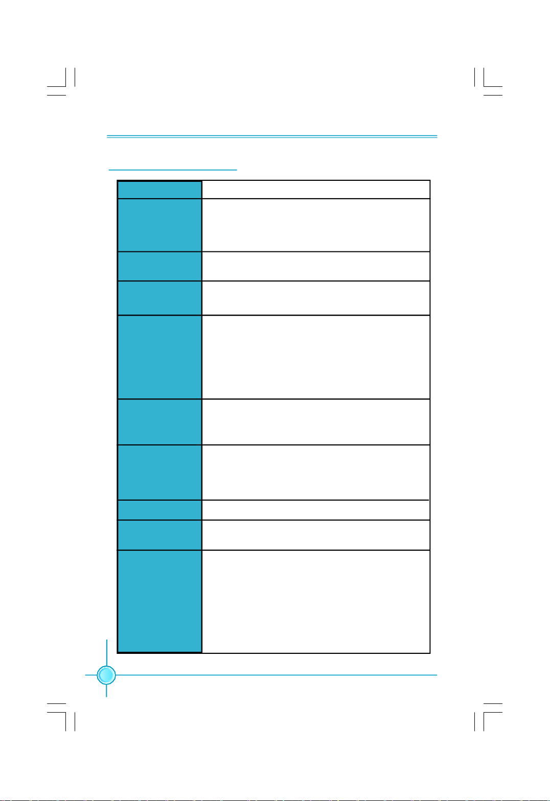
Specifications - - English
Size
CPU
Chipset
Front Side Bus
Memory
Expansion Slots
Audio
·Micro ATX form factor : 244mm x 208mm
· LGA775 socket for Intel
Extreme, CoreTM 2 Duo, Pentium® Dual-Core,
Pentium® 4 Extreme Edition(90nm), Pentium® D, Pentium
4, Celeron® processors
·Northbridge: Intel® G31 / 946GZ
·Southbridge: Intel® ICH7
·1333/1066/800 MHz (for G31)
·1066/800/533 MHz (for 946GZ)
·2 x 240-pin DIMM slots
·Supports Dual-Channel DDR2 800/667 (for G31)
·Supports Dual-Channel DDR2 667/533 (for 946GZ)
·Supports up to 4GB
·1 x PCI Express x16 slot
·1 x PCI Express x1 slot
·2 x PCI slots
·Realtek 6-channel Audio CODEC / Realtek 8-channel
Audio CODEC
·Supports S/PDIF output, Jack-Sensing function, Intel
High Definition Audio
®
CoreTM 2 Quad, CoreTM 2
®
®
LAN
Storage
Rear Panel I/O
2
·Realtek 10/100 Mb/s LAN Controller / Realtek Gigabit
LAN Controller
·2 x Ultra DMA 100/66/33 devices
·4 x SATA 300MB/s devices
·1 x PS/2 Mouse Port
·1 x PS/2 Keyboard Port
·1 x Serial Port
·1 x Parallel Port
·1 x VGA Port
·4 x USB 2.0 Ports
·1 x RJ45 LAN Port
·6/8-channel Audio Ports
(continued on the next page)
Page 9

Chapter 1 Main Features
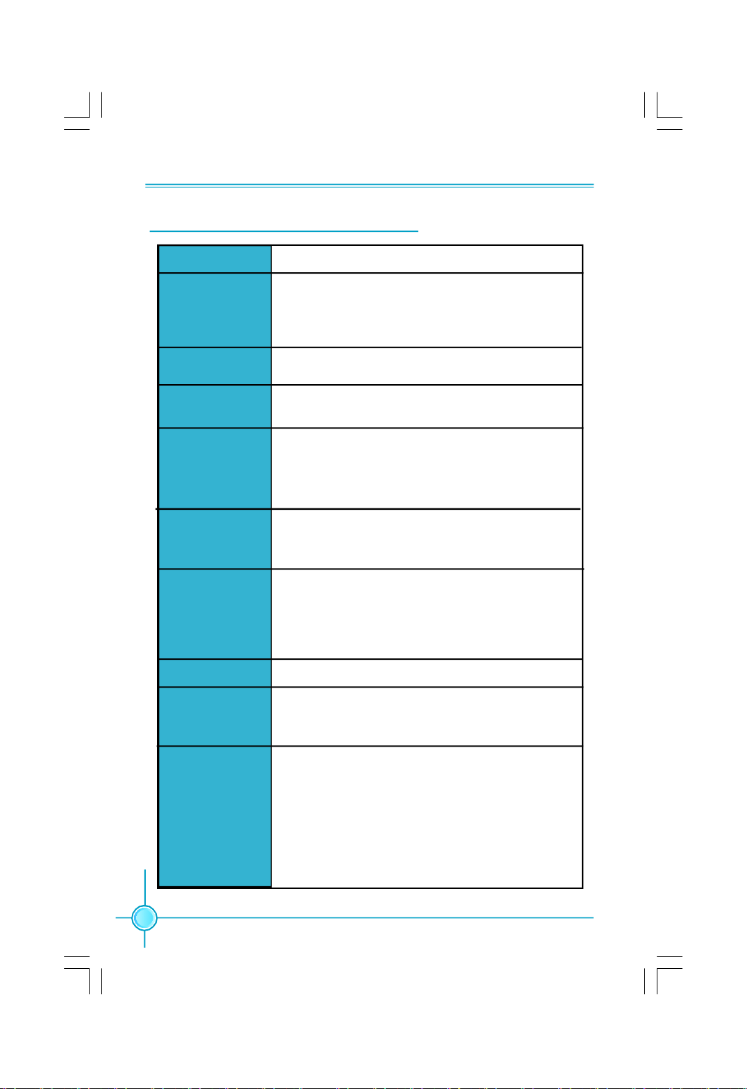
Internal I/O
Connectors
Support CD
·2 x USB 2.0 headers(supports 4 USB 2.0 ports)
·4 x SATA connectors
·1 x Floppy connector
·1 x IDE connector
·1 x Chassis intruder header(INTR)
·1 x CD_IN header
·1 x Speaker header (optional)
·1 x S/PDIF_OUT header
·1 x TPM header (optional)
·1 x COM2 header (optional)
·1 x Front Audio connector
·1 x 24-pin ATX Power connector
·1 x 4-pin ATX_12V Power connector
·1 x IrDA header (optional)
·1 x CPU Fan connector
·1 x System Fan connector
·1 x NB Fan connector (optional)
·Front panel connector
·Driver
·Utility
·Specifications are subject to change without notice
3
Page 10

第一章
主要性能
产品规格- -
尺寸
中央处理器
芯片组
系统总线
内存
扩展槽
音频
简体中文
· uATX 结构: 244mm x 208mm
· 支持采用 LGA775 封装的 Intel® CoreTM 2
Quad,CoreTM 2 Extreme,CoreTM 2 Duo,Pentium
®
Dual-Core, Pentium® 4 Extreme Edition(90nm),
Pentium® D, Pentium® 4, Celeron
®
处理器
·北桥:Intel® G31/946GZ
·南桥:Intel® ICH7
·1333/1066/800 MHz (G31)
·1066/800/533 MHz (946GZ)
·2 个 240针脚内存插槽
· 支持双通道 DDR2 800/667(G31)
· 支持双通道 DDR2 667/533(946GZ)
· 内存总容量最大可达 4GB
·1 个 PCI Express x16 插槽
·1 个 PCI Express x1 插槽
·2 个 PCI 插槽
·Realtek 6 声道音频编解码器 / Realtek 8 声道音
频编解码器
·支持 S/PDIF 输出,Jack-Sensing 功能, Intel
High Definition Audio
®
LAN
存储
后面板I/O
4
·Realtek 10/100 Mb/s LAN Controller / Realtek
Gigabit LAN Controller
·2 个 Ultra DMA 100/66/33 设备
· 4 个 SATA 300MB/s 设备
·1 个 PS/2 鼠标接口
·1 个 PS/2 键盘接口
·1 个 串行接口
·1 个 并行接口
·1 个 VGA 接口
·4 个 USB 2.0 接口
·1 个 RJ45 网络接口
·6/8声道音频接口
(下页继续)
Page 11

第一章
主要性能
内置连接器
实用程序光盘
·规格若有任何更改,恕不另行通知
·2 个 USB 2.0 接头(提供 4 USB 2.0 接口)
·4 个 SATA 接头
·1 个 软驱接口
·1 个 IDE 接口
·1 个 机箱开启侦测接头
·1 个 CD_IN 接头
·1 个 Speaker 接头(选配)
·1 个 S/PDIF_OUT 接头
·1 个 COM2 接头(选配)
·1 个 TPM 接头(选配)
·1 个 前置音频接头
·1 个 24 针ATX 电源接口
·1 个 4 针 ATX_12V 电源接口
·1 个 红外线通讯接头(选配)
·1 个 CPU 风扇接头
·1 个 系统风扇接头
·1 个 北桥风扇接头(选配)
·前端面板接头
·驱动程序
·应用程序
5
Page 12

Kapitel 1 Hauptmerkmale
Technische Daten--Deutsch
Größe
CPU
Chipsatz
Front Side Bus
Speicher
Erweiterungs
steckplätze
Audio
·Micro ATX-Formfaktor: 244 mm x 208 mm
· LGA775-Sockel für Intel®_ CoreTM 2 Quad-, CoreTM 2
Extreme-, CoreTM 2 Duo-, Pentium®_Dual-Core-,
Pentium®_4 Extreme Edition(90nm)-, Pentium®_D-,
Pentium®_4-, Celeron®-Prozessoren
·Northbridge: Intel G31 / 946GZ
·Southbridge: Intel ICH7
·1333/1066/800 MHz (für G31)
·1066/800/533 MHz (für 946GZ)
·2 x 240-polige DIMM-Steckplätze
·Unterstützt Dual-Channel DDR2 800/667 (für G31)
·Unterstützt Dual-Channel DDR2 667/533 (für 946GZ)
·Unterstützt bis 4GB
·1 x PCI Express x16-Steckplatz
·1 x PCI Express x1-Steckplatz
·2 x PCI-Steckplätze
·Realtek 6-Kanal-Audio CODEC / Realtek 8-Kanal-Audio
CODEC
·Unterstützt S/PDIF-Ausgang, Anschlusserkennung, Intel®
High Definition Audio
LAN
Speichergeräte
I/O-Anschlüsse an
der Rückseite
6
·Realtek 10/100 Mb/s / Realtek Gigabit LAN
·2 x Ultra DMA 100/66/33-Geräte
·4 x SATA-Geräte, 300 MB/s
·1 x PS/2-Mausanschluss
·1 x PS/2-Tastaturanschluss
·1 x Seriellanschluss
·1 x Parallelanschluss
·1 x VGA-Port
·4 x USB 2.0-Ports
·1 x RJ45-LAN-Port
·6/8-Kanal-Audio-Ports
(Fortsetzung auf der nächsten Seite)
Page 13

Kapitel 1 Hauptmerkmale
Interne I/OAnschlüsse
Support-CD
·2 x USB 2.0-Anschlussleisten (Unterstützung für 4 USB
2.0-Ports)
·4 x SATA-Anschlüsse
·1 x Diskettenlaufwerkanschluss
·1 x IDE-Anschluss
·1 x Gehäuse-offen-Anschluss (INTR)
·1 x CD_IN-Anschluss
·1 x Lautsprecher-Anschluss (optional)
·1 x S/PDIF_OUT-Anschluss
·1 x TPM-Anschluss (optional)
·1 x COM2-Anschluss (optional)
·1 x Front-Audio-Anschluss
·1 x ATX Power, 24-polig-Anschluss
·1 x ATX_12V Power, 4-polig-Anschluss
·1 x IrDA-Anschluss (optional)
·1 x CPU-Lüfter-Anschluss
·1 x Systemlüfter-Anschluss
·1 x NB-Lüfter-Anschluss (optional)
·Frontbedienfeld-Anschluss
·Treibe
·Dienstprogramme
·Angaben können sich ohne Vorankündigung ändern.
7
Page 14

Capítulo 1 Principales funciones
Características- - Español
Tamaño
CPU
Conjunto de chips
Bus frontal
Memoria
Ranuras
de expansión
Audio
·Micro ATX factor de forma: 244mm x 208mm
· Conector LGA775 para procesadores Intel® CoreTM 2
Quad, CoreTM 2 Extreme, CoreTM 2 Duo, Pentium® Dual Core, Pentium® 4 Extreme Edition(90nm), Pentium® 4,
Pentium® D, Celeron®
·Northbridge: Intel G31 / 946GZ
·Southbridge: Intel ICH7
·1333/1066/800 MHz (para G31)
·1066/800/533 MHz (para 946GZ)
·2 x ranuras DIMM de 240-pin
·Compatible DDR 2 de doble canal 800/667 (para G31)
·Compatible DDR 2 de doble canal 667/533 (para 946GZ)
·Compatible con hasta 4GB
·1 x ranura PCI Express x16
·1 x ranura PCI Express x1
·2 x ranuras PCI
·Realtek 6 canales Audio CODEC / Realtek 8 canales Audio
CODEC
·Compatible salida S/PDIF, sensible a conexión, sonido
Intel® de Alta Definición
LAN
Almacenamiento
Panel de E/S
trasero
8
·Realtek 10/100 Mb/s LAN / Realtek Gigabit LAN
·2 x dispositivos Ultra DMA 100/66/33
·4 x dispositivos SATA 300MB/s
·1 x Puerto de ratón PS/2
·1 x Puerto de teclado PS/2
·1 x Puerto Serie
·1 x Puerto Paralelo
·1 x Puerto de VGA
·4 x Puertos USB 2.0
·1 x Puerto LAN RJ45
·Puertos de 6/8 canales Audio
(continúa en la página siguiente)
Page 15

Capítulo 1 Principales funciones
Conectores
internos de E/S
CD de soporte
·2 x Cabeceras USB 2.0 (admite 4 puertos USB 2.0)
·4 x Conectores SATA
·1 x Conector de disco flexible
·1 x Conector de IDE
·1 x Cabecera de intrusos en bastidor (INTR)
·1 x Cabecera de CD_IN
·1 x Cabecera de altavoz (opcional)
·1 x Cabecera S/PDIF_OUT
·1 x Cabecera TPM (opcional)
·1 x Conector de COM2 (opcional)
·1 x Conector de Audio frontal
·1 x Conector de 24-pin ATX Power
·1 x Conector de 4-pin ATX_12V Power
·1 x Cabecera de IrDA (opcional)
·1 x Conector de ventilador de CPU
·1 x Conector de ventilador de Sistema
·1 x Conector de ventilador NB (opcional)
·Conector de panel frontal
·Controlador
·Utilidades
·Las características se encuentran sujetas a cambios sin aviso previo.
9
Page 16
Capítulo 1 Principais características
Especificações- -Portugués
Tamanho
CPU
Chipset
FSB (Front Side
Bus)
Memória
Ranhuras de
expansão
Áudio
·Factor de forma Micro ATX de 244 x 208 mm
· Socket LGA775 para processadores Intel®_ CoreTM 2
Quad, CoreTM 2 Extreme, CoreTM 2 Duo, Pentium®_Dual Core, Pentium®_4 Extreme Edition(90nm), Pentium®_D,
Pentium®_4, Celeron®
·Northbridge: Intel G31 / 946GZ
·Southbridge: Intel ICH7
·1333/1066/800 MHz ( para o G31)
·1066/800/533 MHz (para o 946GZ)
·2 ranhuras DIMM de 240 pinos
·Suporta módulos de memória DDR2 800/667 de canal
duplo (para o G31)
·Suporta módulos de memória DDR2 667/533 de canal
duplo (para o 946GZ)
·Suporta até 4 GB
·1 ranhura PCI Express x16
·1 ranhura PCI Express x1
·2 ranhuras PCI
·Realtek com 6 canais, codec de áudio / Realtek com 8
canais, codec de áudio
·Suporta saída S/PDIF, função Jack-Sensing, áudio de alta
definição da Intel®
LAN
Armazenamento
Entrada/Saída
pelo painel
traseiro
10
·Realtek 10/100 Mb/s LAN / Realtek Gigabit LAN
· 2 dispositivos Ultra DMA 100/66/33
· 4 dispositivos SATA de 300 MB/s
·1 x Porta para rato PS/2
·1 x Porta para Teclado PS/2
·1 x Porta série
·1 x Porta paralela
·1 x Porta VGA
·4 x Portas USB 2.0
·1 x Porta LAN RJ45
·Portas 6/8 canais, áudio
(continua na página seguinte)
Page 17

Capítulo 1 Principais características
Conectores
internos de
entrada/saída
CD de suporte
·2 x Conectores USB 2.0 (para 4 portas USB 2.0)
·4 x Conectores SATA
·1 x Conector da unidade de disquetes
·1 x Conector IDE
·1 x Conector para detecção de intrusão no chassis(INTR)
·1 x Conector CD_IN
·1 x Conector de altifalante (opcional)
·1 x Conector S/PDIF_OUT
·1 x Conector TPM (opcional)
·1 x Conector COM2 (opcional)
·1 x Conector Áudio frontal
·1 x Conector de alimentação ATX de 24 pinos
·1 x Conector de alimentação ATX de 4 pinos e de 12 V
·1 x Conector IrDA (opcional)
·1 x Conector da ventoinha da CPU
·1 x Conector ventoinha do sistema
·1 x Conector da ventoinha NB(opcional)
·Conector de painel frontal
·Controlador
·Utilitários
·As especificações estão sujeitas a alteração sem aviso prévio.
11
Page 18

Capitolo 1 Caratteristiche principali
Specifiche- -Italiano
Dimensioni
CPU
Chipset
FSB (Front Side
Bus)
Memoria
Alloggi
d’espansione
Audio
·Formato micro ATX: 244 mm x 208 mm
· Socket LGA775 per processori Intel ® CoreTM 2
Quad, CoreTM 2 Extreme, CoreTM 2 Duo, Pentium® Dual Core, Pentium® 4 Extreme Edition(90nm), Pentium® D,
Pentium® 4, Celeron®
·Northbridge: Intel G31 / 946GZ
·Southbridge: Intel ICH7
· 1333/1066/800 MHz (per G31)
· 1066/800/533 MHz (per 946GZ)
·2 alloggi DIMM 240 pin
·Supporto DDR2 800/667 Dual-Channel (per G31)
·Supporto DDR2 667/533 Dual-Channel (per 946GZ)
·Supporto fino a 4GB
·1 Alloggio PCI Express x16
·1 Alloggio PCI Express x1
·2 Alloggi PCI
·Realtek 6-canali audio CODEC / Realtek 8-canali audio
CODEC
·Supporto output S/PDIF, funzione di rilevamento
connettori, Intel® High Definition Audio
LAN
Archivio
Pannello
posteriore I/O
12
·Realtek 10/100 Mb/s LAN / Realtek Gigabit LAN
·2 dispositivi Ultra DMA 100/66/33
·4 dispositivi SATA 300MB/s
·1 x Porta mouse PS/2
·1 x Porta tastiera PS/2
·1 x Porta Seriale
·1 x Porta Parallela
·1 x Porta VGA
·4 x Porta USB 2.0
·1 x Porta LAN RJ45
·Porta 6/8-canali audio
(segue alla pagina successiva)
Page 19

Capitolo 1 Caratteristiche principali
Connettori I/O
interni
CD di supporto
·2 x Collettori USB 2.0 (supportano 4 porte USB 2.0)
·4 x Connettori SATA
·1 x Connettore Floppy
·1 x Connettore IDE
·1 x Collettore intrusione telaio (INTR)
·1 x Collettore CD_IN
·1 x Collettore altoparlante (optional)
·1 x Collettore S/PDIF_OUT
·1 x Collettore TPM (optional)
·1 x Collettore COM2 (optional)
·1 x Connettore Audio frontale
·1 x Connettore potenza ATX 24 pin
·1 x Connettore potenza ATX_12V 4 pin
·1 x Connettore IrDA (optional)
·1 x Connettore ventolina CPU
·1 x Connettore ventolina di sistema
·1 x Connettore ventolina NB (optional)
·Connettore pannello frontale
·Driver
·Utilità
·Le specifiche tecniche sono soggette a cambiamenti senza preavviso.
13
Page 20
Глава 1 Основные характеристики
Технические характеристики- -Русский
Размер
Процессор
Набор микросхем
Частота
системной шин
Память
Слоты
расширения
Звук
·Форм-фактор микро-ATX размером 244 х 208 мм
· Гнездо LGA775 для процессоров Intel®_ CoreTM 2
Quad, CoreTM 2 Extreme, CoreTM 2 Duo, Pentium®_Dual Core, Pentium®_4 Extreme Edition(90nm), Pentium®_D,
Pentium®_4, Celeron®
·Северный мост: Intel G31 / 946GZ
·Южный мост: Intel ICH7
·1333, 1066, 800 МГц (для G31)
·1066, 800, 533 МГц (для 946GZ)
·2 240-контактных гнезда DIMM
·Двухканальная память DDR2 800, 667 (для G31)
·Двухканальная память DDR2 667, 533 (для 946GZ)
·Поддержка до 4 Гб
·1 слот PCI Express x16
·1 слот PCI Express x1
·2 слота PCI
·Realtek 6 каналов, звуковой КОДЕК, Realtek 8
каналов, звуковой КОДЕК
·Поддержка Выход S/PDIF, функция определения
разъема, поддержка технологии Intel® High Definition
Audio
ЛВС
Устройство
хранения
Входы и
выходы на
задней панели
14
·Realtek 10/100 Мбит/с ЛВС, Realtek Gigabit ЛВС
·2 устройств с интерфейсом Ultra DMA 100, 66, 33
·4 устройств с интерфейсом SATA и скоростью
передачи данных 300 Мб/с
·1 Порт мыши PS/2
·1 Порт Клавиатура PS/2
·1 Последовательный порт
·1 Параллельный порт
·1 Порт VGA
·4 Порты USB 2.0
·1 Разъем ЛВС RJ45
·Порты 6, 8 каналов, звуковой
(продолжение на следующей странице)
Page 21

Глава 1 Основные характеристики
Встроенные
входы и
выходы
Поддержка
компакт-дисков
·2 Разъемы USB 2.0 (поддержка 4 портов USB 2.0)
·4 Разъемы SATA
·1 Разъем дисковода гибких дисков
·1 Разъем IDE
·1 Разъем датчика открывания корпуса (INTR)
·1 Разъем CD_IN
·1 Разъем Динамик (дополнительный)
·1 Разъем выход S/PDIF
·1 Разъем TPM (дополнительный)
·1 Разъем COM2 (дополнительный)
·1 Передний звуковой разъем
·1 Разъем 24-контактный ATX
·1 Разъем 4-контактый ATX_12V
·1 Разъем ИК-порт (дополнительный)
·1 Разъем Вентилятор процессора
·1 Разъем системный Вентилятор
·1 Разъем Вентилятор северного моста
(дополнительный)
·Передняя панель разъем
·Драйвер
·Служебная программа
·Технические характеристики могут изменяться без уведомления.
15
Page 22

ﻞﺼﻔﻟا1ﺔﯿﺴﯿﺋﺮﻟا ﺺﺋﺎﺼﺨﻟا
تﺎﻔﺻاﻮﻤﻟا
ﺔ ﯿﺑﺮﻌﻟ- -
Ÿ عﻮﻧ ﻦﻣ ﺔﯾوﺎﺣ Micro ATX سﺎﻘﻣ 244 ﻢﻣ× 208ﻢﻣ
Ÿ ﺲﺒﻘﻣ LGA775 تﺎﺠﻟﺎﻌﻤﻟ Intel®_ CoreTM 2 Quad و CoreTM 2
ﺔﯾﺰﻛﺮﻤﻟا ﺔﺠﻟﺎﻌﻤﻟا ةﺪﺣو
Extreme وCoreTM 2 Duoو Pentium®_Dual-Core وPentium®_4
(90nm) Edition Extremeو Pentium®_Dو Pentium®_4 و Celeron®.
Ÿ ﻲﻟﺎﻤﺸﻟا ﺮﺴﺠﻟا)Northbridge(: Intel G31/946GZ
Ÿ ) ﻲﺑﻮﻨﺠﻟا ﺮﺴﺠﻟاSouthbridge(: Intel ICH7
Ÿ 1333 / 1066 / 800ﺰﺗﺮھ ﺎﺠﯿﻣ ( G31)
ﻲﻣﺎﻣﻷا ﺐﻧﺎﺠﻟا ﻞﻗﺎﻧ
Ÿ 533/800/1066ﺰﺗﺮھ ﺎﺠﯿﻣ (946GZ)
Ÿ دﺪﻋ2 تﺎﺤﺘﻓDIMM × 240 ﺎﺳﻮ ﺑد
Ÿ ةﺎﻨﻘﻟا ﻲﺋﺎﻨﺛ ﻢﯿﻤﺼﺘﻟا ﻢﻋدDual-Channel DDR2 800/667 (G31)
Ÿ ةﺎﻨﻘﻟا ﻲﺋﺎﻨﺛ ﻢﯿﻤﺼﺘﻟا ﻢﻋدDual-Channel DDR2 667/533 (946GZ)
Ÿ ﻰﻟإ ﻞﺼﯾ ﻢﻋد4ﺖﯾﺎﺑ ﺎﺠﯿﺟ
Ÿ دﺪﻋ1 ﺢﺘﻓة PCI Express x16
Ÿ دﺪﻋ1 ﺔﺤﺘﻓPCI Express x1
Ÿ دﺪﻋ2 ت ﺎ ﺤﺘﻓ PCI
Ÿ ﺔﯿﻨﻘﺘﺑ تاﻮﻨﻗ ﺖﺴﺑ ﻲﺗﻮﺻ ﺰﯿﻣﺮﺗ Realtek / ﺰﯿﻣﺮﺗ ﻲﺗﻮﺻ نﺎﻤﺜﺑ تاﻮﻨﻗ ﺔﯿﻨﻘﺘﺑ Realtek
Ÿ جﺮﺧ ﻢﻋدS/PDIFﺔﯿﻨﻘﺗ ،ﺲﺒﻘﻤﻟا رﺎﻌﺸﺘﺳا ﺔﻔﯿﻇو ، Intel® High Definition Audio
ﺔﯿﻠﺤﻤﻟا لﺎﺼﺗﻻا ﺔﻜﺒﺷ
Ÿ Realtek Gigabit LAN / Realtek 10/100 Mb/s LAN
ﻢﺠﺤﻟا
ﻖﺋﺎﻗﺮﻟا
ةﺮﻛا ﺬﻟا
ﺔﻌﺳﻮﺘﻟا تﺎﺤﺘﻓ
تﻮﺼﻟا
16
Ÿ دﺪﻋ1 Ultra DMA 100/ 66 /33
Ÿ دﺪﻋ4 ةﺰﮭﺟأSATA 300MB/s
Ÿ دﺪﻋ1 سوﺎﻣ ﺬﻔﻨﻣPS/2
Ÿ دﺪﻋ1 ﺢﯿﺗﺎﻔﻣ ﺔﺣﻮﻟ ﺬﻔﻨﻣPS/2
Ÿ دﺪﻋ1 ﻲﻠﺴﻠﺴﺗ ﺬﻔﻨﻣ
Ÿ دﺪﻋ1 يزاﻮﺘﻣ ﺬﻔﻨﻣ
Ÿ دﺪﻋ1 ﺬﻔﻨﻣVGA
Ÿ دﺪﻋ4 ﺬﻓﺎﻨﻣUSB 2.0
Ÿ دﺪﻋ1 ﺔﯿﻠﺤﻣ لﺎﺼﺗا ﺔﻜﺒﺷ ﺬﻔﻨﻣRJ45
Ÿ ﺬﻔﻨﻣ/ ﺖﺴﺑ ﻲﺗﻮﺻ نﺎﻤﺜﺑ ﺔﯿﻨﻘﺘﺑ تاﻮﻨﻗ
ﻦﯾﺰﺨﺘﻟا
ﺬﻓﺎﻨﻣ ﺔﺣﻮﻠﻟ جﺮﺨﻟا/ ﻞﺧﺪﻟا
ﺔﯿﻔﻠﺨﻟا
ﺔﯿﻟﺎﺘﻟا ﺔﺤﻔﺼﻟا ﻊﺑﺎﺗ
Page 23

Ÿ دﺪﻋ2 فاﺮﻃأ ﻞﯿﺻﻮﺗ USB 2.0) ﻢﻋﺪﺗ 4 ﺬﻓﺎﻨﻣ USB 2.0(
جﺮﺨﻟا / ﻞﺧﺪﻟا ﻞﯿﺻﻮﺗ ﺬﻓﺎﻨﻣ
Ÿ دﺪﻋ4 ﻞﯿﺻﻮﺗ ﺬﻓﺎﻨﻣSATA
Ÿ دﺪﻋ1ﺔﻧﺮﻤﻟا صاﺮﻗﻷا كﺮﺤﻣ ﻞﯿﺻﻮﺗ ﺬﻔﻨﻣ
Ÿ دﺪﻋ1 ﻞﯿﺻﻮﺗ ﺬﻔﻨﻣ IDE
Ÿ دﺪﻋ1 ﻞﯿﺻﻮﺗ فﺮﻃ Intruder ﻞﻜﯿﮭﻠﻟ ) INTR (
Ÿ دﺪﻋ1 ﻞﯿﺻﻮ ﺗ فﺮﻃ CD_IN
Ÿ دﺪﻋ1ﺔﻋﺎﻤﺴﻟا ﻞﯿﺻﻮ ﺗ فﺮﻃ ) يرﺎﯿﺘﺧا (
Ÿ دﺪﻋ1 جﺮﺧ ﻞﯿﺻﻮﺗ فﺮﻃ S/PDIF
Ÿ دﺪﻋ1 ﻞﯿﺻﻮﺗ فﺮﻃTPM) يرﺎﯿﺘﺧا (
Ÿ دﺪﻋ1 ﻞﯿﺻﻮﺗ فﺮﻃCOM2) يرﺎﯿﺘﺧا (
Ÿ ﻲﻣﺎﻣﻷا تﻮﺼﻟا ﻞﺻﻮﻣ
Ÿ دﺪﻋ1 ﺔﻗﺎﻃ ﻞﺻﻮﻣ ATX ء، 24 سﻮﺑد
Ÿ دﺪﻋ1 ﺔﻗﺎﻃ ﻞﺻﻮﻣ ATX_12V ×4 ﺲﯿﺑﺎﺑد
Ÿ دﺪﻋ 1 ﻞﯿﺻﻮﺗ فﺮﻃ IrDA) يرﺎﯿﺘﺧا (
Ÿ دﺪﻋ1ﺔﯾﺰﻛﺮﻤﻟا ﺔﺠﻟﺎﻌﻤﻟا ةﺪﺣﻮﻟ ﺔﺣوﺮﻣ
Ÿ دﺪﻋ1 مﺎ ﻈﻨﻟا ﺔﺣوﺮﻤﻟ ﻞﺻﻮﻣ
Ÿ دﺪﻋ 1 ﺔﺣوﺮﻣ NB) يرﺎﯿﺘﺧا (
Ÿ ﺔﯿﻣﺎﻣﻷا ﺔﺣﻮﻠﻟا ﻞﺻﻮﻣ
مﺪﻤﻟا صﺮﻘﻟا ﻢﻋد Ÿ ﻞﯿﻐﺸﺘﻟا ﺞﻣﺎﻧﺮﺑ
Ÿ تاودﻷا
ﻞﺼﻔﻟا1ﺔﯿﺴﯿﺋﺮﻟا ﺺﺋﺎﺼﺨﻟا
ﺔﯿﻠﺧاﺪﻟا
Ÿ .ﻖﺒﺴﻣ رﺎﻄﺧإ نوﺪﺑ تﺎﻔﺻاﻮﻤﻟا ﺮﯿﻐﺘﺗ ﺪﻗ
17
Page 24

Chapter 1 Main Features
Jumpers
This section explains how to setup jumpers. You should read the following
content carefully prior to modifying any jumper settings.
Attention
The jumpers on the motherboard, pin 1 can be identified by the
bold silkscreen next to it. And in this manual, pin 1 is simply labeled as “ 1”.
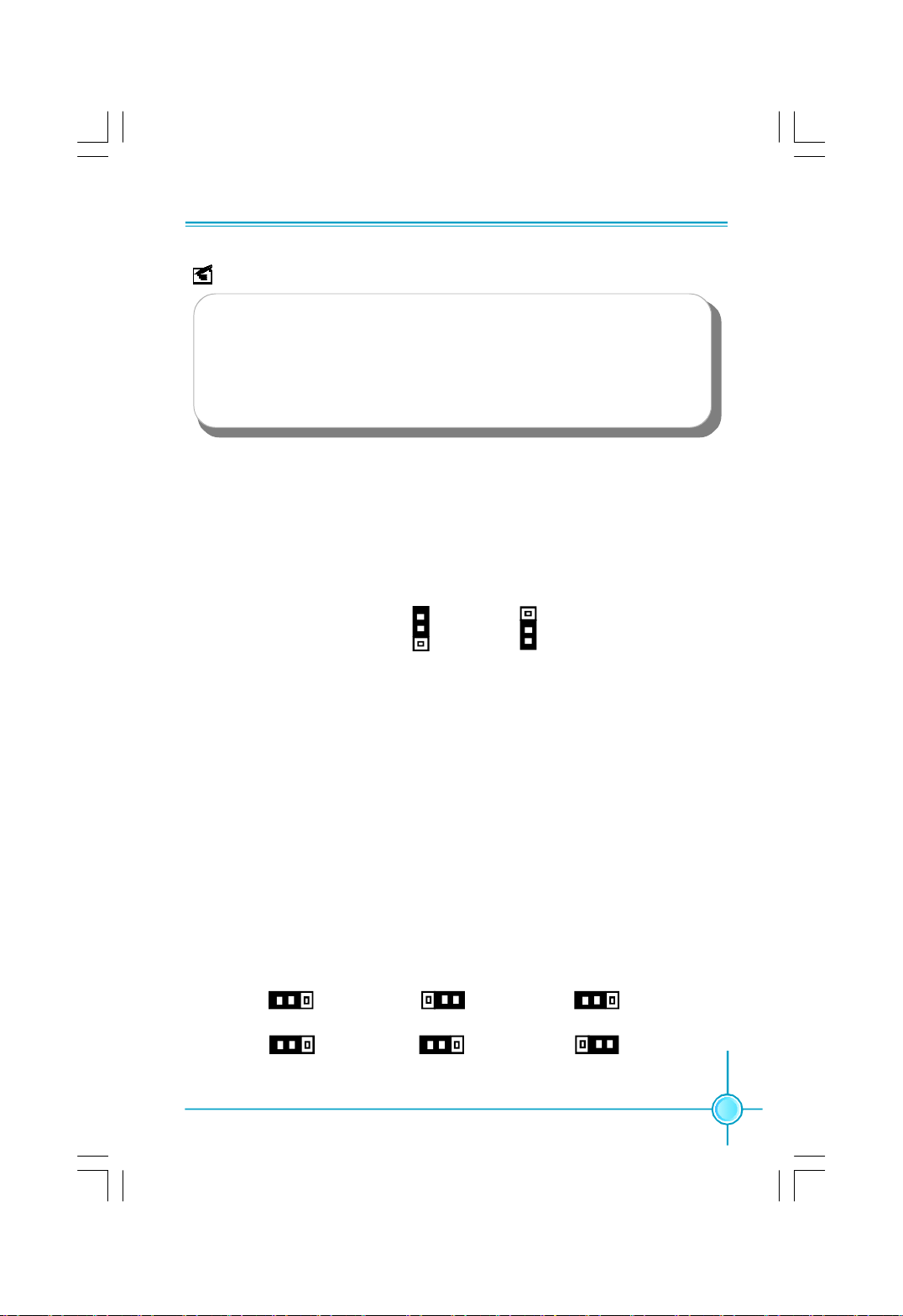
Clear CMOS Jumper: CLR_CMOS
The CLR_CMOS jumper allows you to clear the data in CMOS. The data
includes system setup information such as system password, data, time,
and system setup parameters. To clear and reset the system parameters to
default setup, please do as follows:
1. Turn off the computer and unplug the power cord
from the power supply.
2. Move the jumper cap from pins 2-3 (default) to pins
1-2. Keep the cap on pins 1-2 for several seconds,
then move the cap back to pins 2-3.
3. Plug the power cord and turn on the computer.
CLR_ CMOS
Normal
(default)
Clear
1
1
USB device wake-up Jumper: USBPW1357_1/USBPW0246_1
1.Set the jumper to pins 1-2 (+5V) to wake up the computer from S1 sleep mode
using the connected USB devices.
2.Set the jumper to pins 2-3 (+5VSB) to wake up the computer from S3 sleep
mode using the connected USB devices. At the same time, a corresponding
setting must be set in BIOS as below:
Set “CMOS Setup”->“Power Management Setup”->“Power Management Events”-
>“USB KB Wake-Up From S3” to “Enabled”.
1
+5VSB
USBPW1357_1/USBPW0246_1
+5V
(Default)
1
18
Page 25
Chapter 1 Main Features
Note
1. USBPW0246_1 is for the internal USB connectors, USBPW1357_1 is for the rear
USB ports.
2. The USB device wake-up feature requires a power supply that can provide 500mA
on +5VSB lead for each USB port; otherwise, the system will not power up.
3. The total current consumed must not exceed the power supply capability (+5VSB)
whether under normal condition or in sleep mode.
Keyboard and Mouse Jumper: KB/MS_PW
This jumper allows you to enable or disable the Keyboard and Mouse wake-up
feature. Set the jumper to pins 2-3(+5VSB) to wake up the computer from S3 and
S4 sleep modes when you press a key on the keyboard or move the mouse, and
a corresponding setting in the BIOS.
+5V
(Default)
1
KB/MS_PW
1
+5VSB
Over Memory Frequency Jumper: JP1, JP2 (for G31MX Series)
When you use the memory which support 1066, the jumpers are used to
overclock memory frequency. At the same time, the overclock bound depend on
CPU FSB, you can achieve the function as below.
1.When the CPU FSB is 1066MHz, set the JP1 pins to 2-3(as status 1), and set
“CMOS Setup”->”Fox Central Control Unit”->”DRAM Configuration”->”DRAM
Timing Selectable” to “Manual”, “System Memory Frequency” will show 886 and
1066.
2.When the CPU FSB is 1333MHz, set the JP2 pins to 2-3(as status 2), and set
“CMOS Setup”->”Fox Central Control Unit”->”DRAM Configuration”->”DRAM
Timing Selectable” to “Manual”, “System Memory Frequency” will show 1000.
1
JP1
1
JP2
1
JP1
1
JP2
Status 1
1
JP1
1
JP2
Status 2Default
19
Page 26

Chapter 2 BIOS Description
Chapter
20
2
This chapter introduces how to change system settings
through the BIOS Setup menus. Detailed descriptions of the
BIOS parameters are also provided.
You have to run the Setup Program when the following cases
occur:
1.An error message appears on the screen during the system
POST process.
2.You want to change the default CMOS settings.
This chapter includes the following information:
v Enter BIOS Setup
v Main Menu
v Standard CMOS Features
v FOX Central Control Unit
v Advanced BIOS Features
v Advanced Chipset Features
v Integrated Peripherals
v Security Chip Configuration
v Power Management Setup
v PC Health Status
v Load Optimized Defaults
v Set Supervised Password
v Set User Password
v Save and Exit Setup
v Exit Without Saving
Page 27
Chapter 2 BIOS Description
Enter BIOS Setup
The BIOS is the communication bridge between hardware and software.
Correctly setting up the BIOS parameters is critical to maintain optimal system
performance. Power on the computer, when the following message briefly
appears at the bottom of the screen during the POST (Power On Self Test),
press <Del> key to enter the BIOS CMOS Setup Utility.
Press TAB to show POST Screen, DEL to enter SETUP, Esc to enter Boot
Menu.
Note:
We do not suggest that you change the default parameters in the BIOS Setup,
and we shall not be responsible for any damage that results from any changes
that you make.
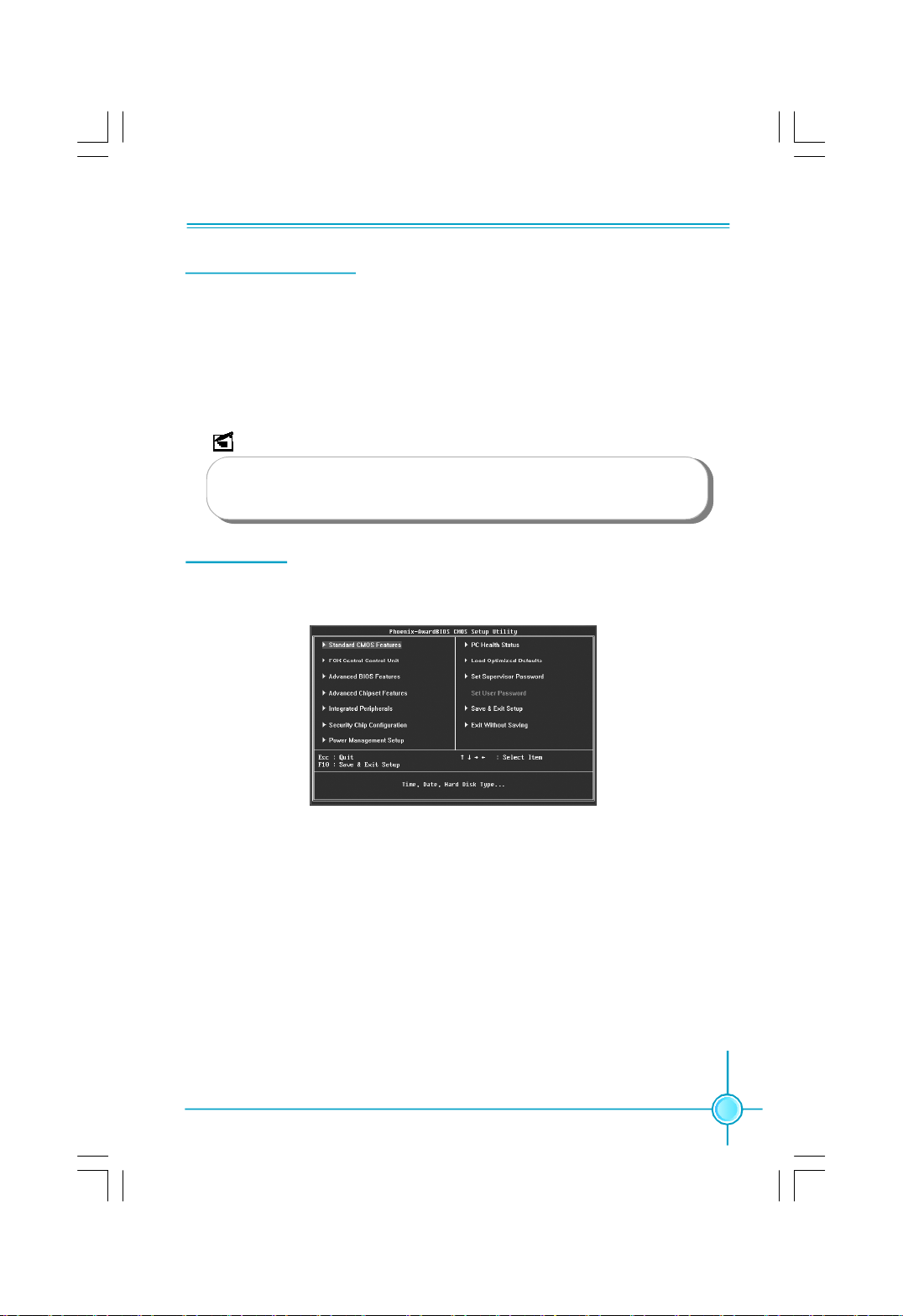
Main Menu
The main menu displays a list of options that are available. Use the arrow keys
to highlight an item, and execute the item by pressing <Enter>.
Main Menu
The items in the main menu are explained as below:
1. Standard CMOS Features
The basic system configuration can be set up through this menu.
2. FOX Central Control Unit
The special features can be set up by this menu.
3. Advanced BIOS Features
The advanced system features can be set up through this menu.
4. Advanced Chipset Features
The values for the chipset can be changed through this menu, and the sys-
tem performance can be optimized.
5. Integrated Peripherals
All onboard peripherals can be set up through this menu.
21
Page 28
Chapter 2 BIOS Description
6. Security Chip Configuration (optional)
This menu is only for G31MX Series motherboard.
Only the TPM device connected to the computer, this item will appear, you
can press <Enter> to set some parameters of TPM device.
7. Power Management Setup
Through this menu you can set up all the items of Green function features.
8. PC Health Status
This menu will display the current status of your PC.
9. Load Optimized Defaults
You can load the optimal performance settings by this menu; however, the
stable default values may be affected.
10. Set Supervisor Password
The supervisor password can be set up through this menu.
11. Set User Password
The user password can be set up through this menu.
12. Save & Exit Setup
Save CMOS value settings to CMOS and exit setup.
13. Exit Without Saving
Abandon all CMOS value changes and exit setup.
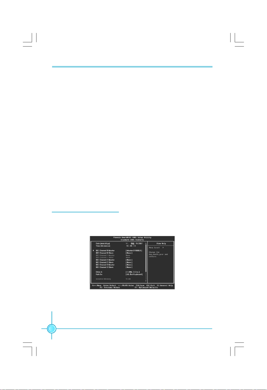
1.Standard CMOS Features
This sub-menu is used to set up the standard CMOS parameters, such as the
date, time, floppy driver and so on. Select the item by the arrow keys, and then
use the <+> or <-> keys to choose the setting values.
Standard CMOS Features Menu
1.1 Date/Time
These item allows you to set up the desired time and date(usually as the
current time and date) with <hour><minute><second><day><month>
<date><year> format.
22
Page 29
Chapter 2 BIOS Description
Day—weekday from Sun. to Sat.
Month—month from 1 to 12
Date—date from 1st to 31
Year—year, set up by users.
Use <ENTER>,<TAB> or <SHIFT+TAB]>to select a field.Use <+>or <-> to
configure system time and date.
1.2 IDE Channel 0/1/2/3 Master/slave
These categories identify the HDD types of 1 IDE channel installed in the
computer system. There are three choices provided for the Enhanced IDE
BIOS: None, Auto, and Manual. “None” means no HDD is installed or set;
“Auto” means the system can auto-detect the hard disk when booting up; by
choosing “Manual” and changing Access Mode to “CHS”, the related informa tion should be entered manually. Enter the information directly from the key board and press < Enter>:
Cylinder number of cylinders Head number of heads
Precomp write pre-compensation Landing Zone landing zone
Sector number of sectors
Award (Phoenix) BIOS can support 3 HDD modes: CHS, LBA and Large.
CHS For HDD<528MB
LBA For HDD>528MB & supporting LBA (Logical Block Addressing)
st
Large For HDD>528MB but not supporting LBA
Note: Set to [Auto] , the system can detect the hard disk and select the
HDD mode automatically when booting up. Suggest you select this option.
1.3 Drive A
This option allows you to select the kind of FDD to be installed, including
[None], [360K, 5.25 in], [1.2M, 5.25 in], [720K, 3.5 in], [1.44M, 3.5 in] and
[2.88 M, 3.5 in].
1.4 Halt On
This category determines whether or not the computer will stop if an error
is detected during powering up.
All Errors Whenever the BIOS detects a nonfatal error, the system
will stop and you will be prompted.
No Errors The system boot will not stop for any errors that may
be detected.
23
Page 30

Chapter 2 BIOS Description
All, But Keyboard The system boot will not stop for a keyboard error; but
it will stop for all other errors.
All, But Diskette The system boot will not stop for a diskette error; but
it will stop for all other errors.
All, But Disk/Key The system boot will not stop for a keyboard or disk
error; but it will stop for other errors.
1.5 Installed Memory
This is a Display-Only Category, showing the capacity of your installed memory.
1.6 BIOS ID
This option shows the BIOS ID.
2.FOX Central Control Unit
FOX Central Control Unit Menu
2.1 SuperBIOS-Protect
SuperBIOS Protect function protects your BIOS from being affected by viruses,
e.g.CIH.
2.2 Current CPU Frequency
This option shows the current frequency of CPU.
2.3 Current FSB Frequency
This option shows the current frequency of FSB.
2.4 Current DRAM Frequency
This option shows the current frequency of DRAM.
2.5 CPU Clock Ratio
This option is used to set the ratio of an unlocked CPU. Using different CPU,
the setting values are different.
2.6 Auto Detect PCI Clk
This option is used to auto detect PCI slots. When enabled, the system will
move(turn off) the empty PCI slot clock to reduce EMI(Electro-Magnetic
Interference).
2.7 FOX Intelligent Stepping
24
Page 31
Chapter 2 BIOS Description
You can select different overclock option by this item. The available setting
values are: Default, Manual, Step1, Step2, Step 3.
2.8 CPU Clock
This option is used to set the CPU clock.
2.9 PCI Express Clock
This option is used to set the PCI Express clock.
2.10 CPU Voltage Regulator
This option is used to regulate the CPU voltage.
2.11 DRAM Voltage Regulator
This option is used to regulate the DRAM voltage.
2.12 Spread Spectrum
When enabled, it can significantly reduce the EMI (Electromagnetic Inter-
ference) generated by the system.
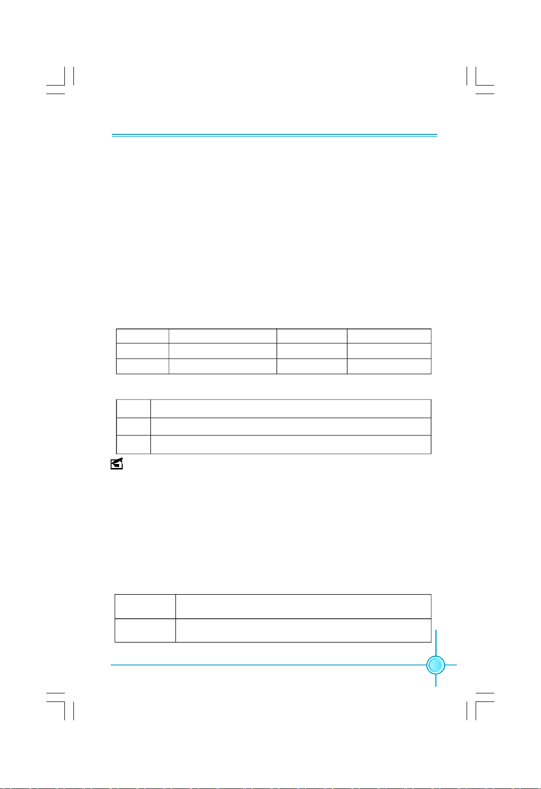
2.13 DRAM Configuration
DRAM Configuration Menu
DRAM Timing Selectable
This item determines DRAM clock/ timing using SPD or manual configuration.
CAS Latency Time
This item determines CAS Latency. The available setting values are: 3, 4, 5
and Auto.
DRAM RAS# to CAS# Delay
This item allows you to select a delay time between the CAS and RAS strobe
signals. The available setting values are: 3, 4, 5, 6 and Auto.
DRAM RAS# Precharge
This item allows you to select the DRAM RAS# precharge time. The available
setting values are: 3, 4, 5, 6 and Auto.
Precharge Delay(tRAS)
This item allows you to set the precharge delay time. The available setting
values are: Auto, 9, 10, 11, 12, 13, 14, 15.
System Memory Frequency
This item allows you to set the memory frequency of your system.
25
Page 32
Chapter 2 BIOS Description
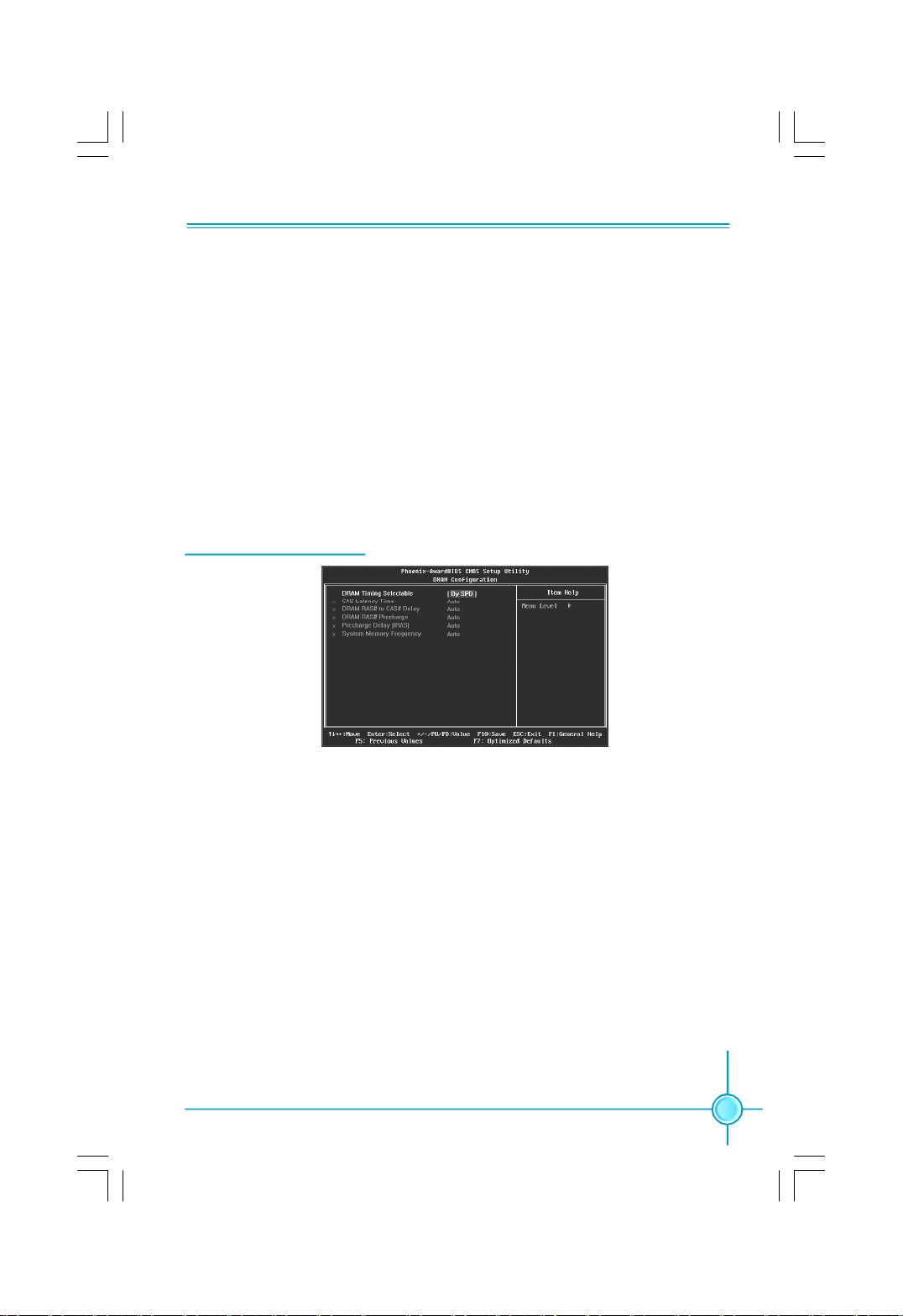
3.Advanced BIOS Features
Advanced BIOS Features Menu
3.1 CPU Feature
You can press <Enter> to set the items of CPU feature.
3.2 Removable Device Priority
This option is used to select the priority for removable device, e.g. floppy.
3.3 Hard Disk Boot Priority
This option is used to select the priority for HDD startup. After pressing
<Enter>, you can select the HDD using the Up / Down arrow keys,
and change the HDD priority using <PageUp> / <PageDn> or <+> / <->;
you can exit this menu by pressing <Esc>.
3.4 CPU L1&L2 Cache
This option is used to turn on or off the L1 and L2 CPU cache.
3.5 Hyper-Threading Technology
Enable or disable Hyper-Threading technology.
3.6 First/Second/Third Boot Device
Allows you to set the boot device’s sequence.
3.7 Boot Other Device
While enabled, the system will boot from some other devices if the first/
second/third boot devices failed.
3.8 Boot Up Floppy Seek
This option controls whether the BIOS checks for a floppy drive while booting
up. If it cannot detect one (either due to improper configuration or physical
unavailability), it will appear an error message.
3.9 Boot Up NumLock Status
Allows you to select the power-on status for the NumLock. The available
setting values are: On and Off.
3.10 Security Option
When it is set to “Setup”, a password is required to enter the CMOS Setup
screen; When it is set to “System”, a password is required not only to enter
CMOS Setup, but also to start up your PC.
26
Page 33

Chapter 2 BIOS Description
3.11 APIC Mode
This option is used to enable or disable APIC function.
3.12 Delay For HDD(Secs)
This option is used to set the delay time of selecting the HDD controller.
3.13 Full Screen LOGO Show
This option allows you to enable or disable the full screen logo.
3.14 Small Logo (EPA) Show
This item allows you to enable or disable the EPA logo.
4.Advanced Chipset Features
Advanced Chipset Features Menu
4.1 PCI Express Root Port Func
This option is used to configure the PCI Express port.
4.2 System BIOS Cacheable
Select ”Enabled” to allow caching of the system BIOS which may improve
performance. If any other program writes to this memory area, a system
error may result.
4.3 Memory Hole At 15M-16M
This item is used to determine whether the 15M-16M address field of memory
is reserved for the ISA expansion card.
4.4 PEG/Onchip VGA Control
This item is used to enable or disable PEG and onboard VGA.
4.5 On-Chip Frame Buffer Size
This item is used to set the VGA frame buffer size.
Note: This function does not work when the external display card is used.
4.6 DVMT Mode
This item is used to set the DVMT mode.
4.7 DVMT/FIXED Memory Size
This item is used to set the DVMT/FIXED memory size.
4.8 Init Display First
This item is used to select the initial display device used when your PC starts
up.
27
Page 34
Chapter 2 BIOS Description
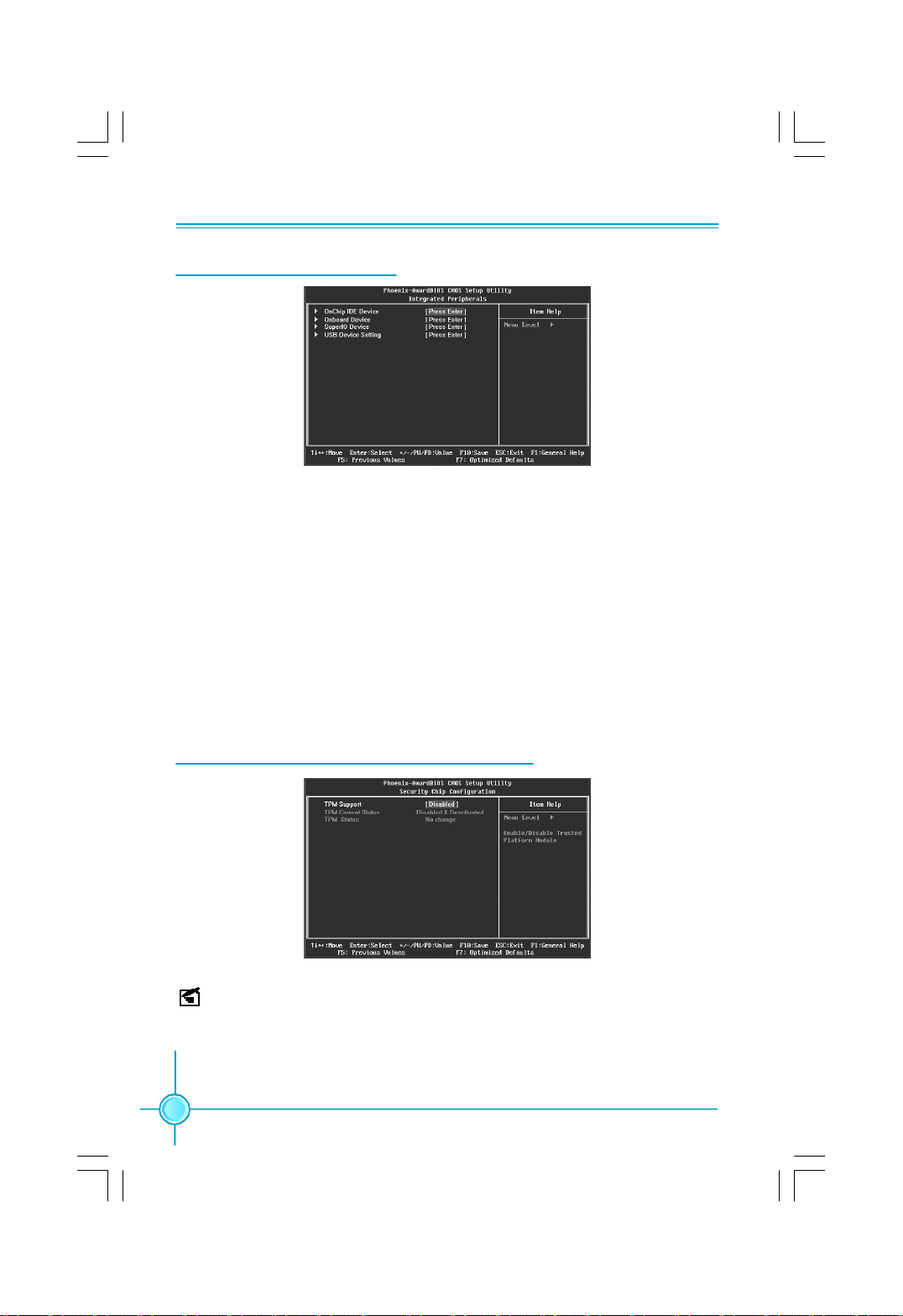
5.Integrated Peripherals
Integrated Peripherals Menu
5.1 OnChip IDE Device
This sub-menu is used for the configuration of IDE devices. You can press
<Enter> to set the avaliable values of items.
5.2 Onboard Device
This sub-menu is used for the configuration of onboard devices.
5.3 SuperIO Device
This sub-menu is used for the configuration of I/O devices, such as serial
port, parallel port and so on.
5.4 USB Device Setting
This sub-menu is used to set the parameters of USB devices.
6.Security Chip Configuration (optional)
Security Chip Configuration Menu
Note: This menu is only for G31MX Series motherboard, and only the TPM
device connected to the computer, this menu will appear, at the same time you
can set some parameters of TPM device.
28
Page 35

Chapter 2 BIOS Description
6.1 TPM Support
This item is used to enable or disable TPM function.
6.2 TPM Current Status
Through this item you can see the current status of TPM device.
6.3 TPM Status
You can set the next status of TPM device when your computer reset. The
available setting values are: No change, Clear, Enable & Active, Deactivate
& Disable.
7.Power Management Setup
Power Management Setup Menu
7.1 PCI Express PM Function
Allows you to set the power management of PCI Express.
7.2 Power Management Events
You can press <Enter> to set the parameters of power management events.
7.3 ACPI Function
ACPI( Advanced Configuration and Power Interface) is a standard that de fines power and configuration management interfaces between an operating
system and the BIOS. In other words, it is a standard that describes how
computer components work together to manage system hardware. In order
to use this function the ACPI specification must be supported by the OS (for
example, Windows2000 or WindowsXP).
7.4 ACPI Suspend Type
This option is used to set the energy saving mode of the ACPI function.
When you select “S1 (POS)” mode, the power will not shut off and the
supply status will remain as it is, in S1 mode the computer can be resumed
at any time. When you select “S3 (STR)” mode, the power will be cut off after
a delay period. The status of the computer before it enters STR will be saved
in memory, and the computer can quickly return to previous status when the
STR function wakes.
29
Page 36
Chapter 2 BIOS Description
7.5 Soft-Off by PWR-BTTN
This option is used to set the power down method.This function is only valid
for systems using an ATX power supply. When select “Instant-off” , once press
power buttton, the power turns off immediately; When select “Delay 4 sec”,
the power will be off after the power button is pressed more than 4 seconds.
7.6 HPET Support
This option allows you to enable or disable High Precision Event Timer function.
If you use windows vista processing system, we intensively suggest that you
set this option to “Enabled”.
7.7 HPET Mode
This option is used to set the High Precision Event Timer mode. The available
setting values are: 32-bit mode, 64-bit mode. It is available only when
“HPET” is enabled.
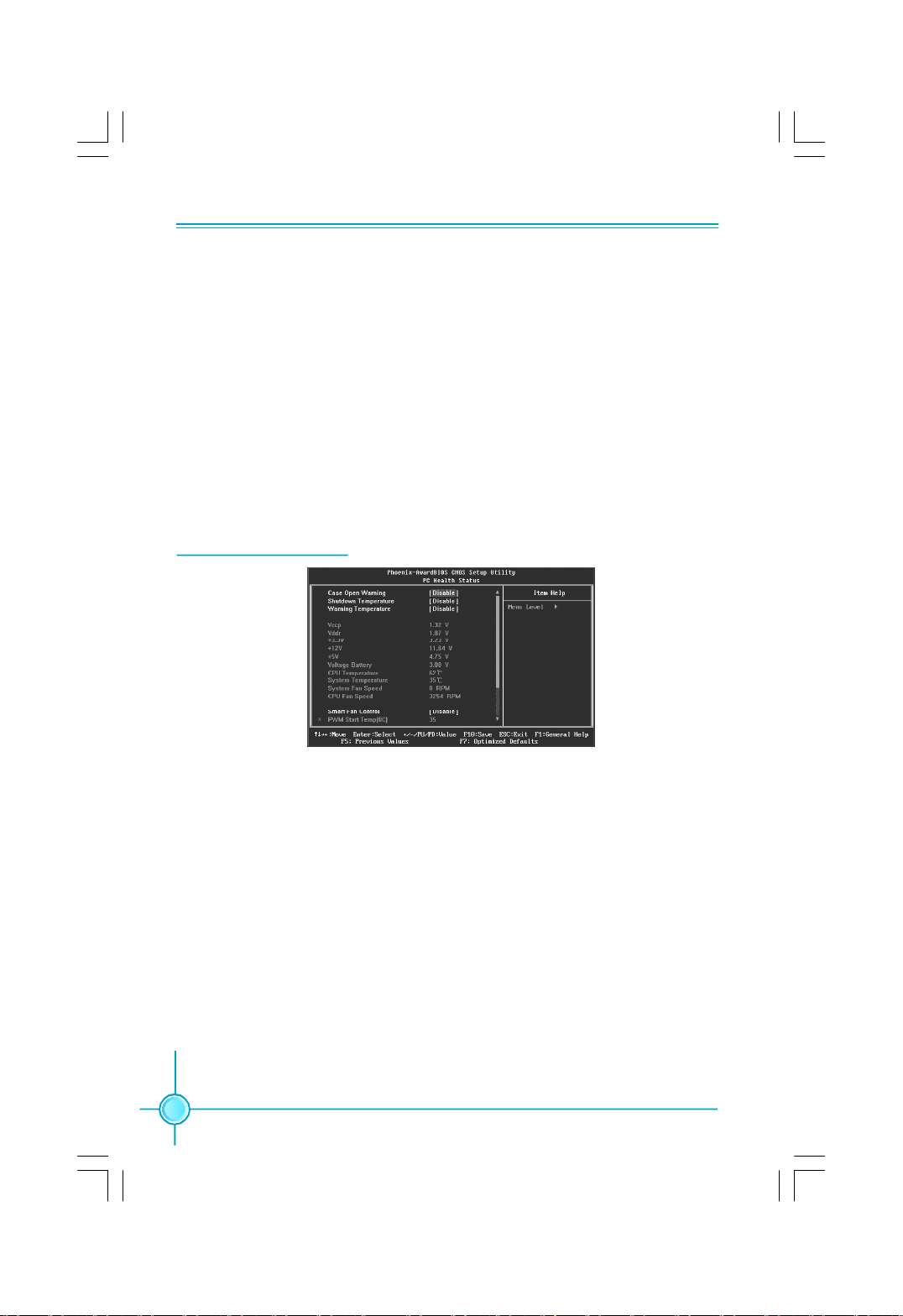
8.PC Health Status
PC Health Status Menu
8.1 Case Open Warning
Enable or disable the chassis open status feature.
8.2 Shutdown Temperature
This option is used to set the high limit system temperature. When the
temperature exceeds the setting value, the motherboard will automatically cut
off power to the computer.
8.3 Warning Temperature
This option is used to set the warning temperature for the system. When the
temperature of CPU is higher than setting value, the motherboard will send
off warning information.
8.4 Vccp/Vddr/+ 3.3V/+12V/+5V
The current voltages will be automatically detected by the system.
8.5 CPU/System Temperature
The current CPU/system temperature will be automatically detected by the
system.
30
Page 37

Chapter 2 BIOS Description
8.6 System/CPU Fan Speed
The current system /CPU fan speed will be automatically detected by the
system.
8.7 Smart Fan Control
This option is used to enable or disable smart fan function. Only when this
option is enabled, you can set some correlative parameters as follows.
PWM Start Temp(℃)
Allows you set the PWM start temperature which is initial temperature of
smart fan. When the temperature achieve the value and “Smart Fan Control”
is enabled, the smart fan will be turn on.
Start PWM Value
This option allows you to set the initial PWM value of smart fan.
Slope PWM Value
This option is used to set slope value of smart fan curve.
Deita Temp(℃)
This option is used to set the temperature delta. When the changeamplit-
ude of temperature achieves the value, the PWM value will increase or
decrease by slope.
9.Load Optimized Defaults
This menu can let you load the optimized defaults set by BIOS, which have set
the optimized performance parameters of system to improve the performances
of system components. You can select <Y> or <N> and then press <Enter> to
load or not load the optimized defaults.
10-11.Set Supervisor/User Password
The access rights and permissions associated with the Supervisor password are
higher than those of a regular User password. The Supervisor password can be
used to start the system or modify the CMOS settings. The User password can
also start the system. While the User password can be used to view the current
CMOS settings, these settings cannot be modified using the User password.
When you select the Set Supervisor/User Password option, the following message
will appear in the center of the screen, which will help you to set the password:
Enter Password:
Enter your password, not exceeding 8 characters, then press <Enter>. The
password you enter will replace any previous password. When prompted, key in
the new password and press <Enter>.
31
Page 38

Chapter 2 BIOS Description
If you do not want to set a password, just press <Enter> when prompted to enter
a password, and in the screen the following message will appear. If no password
is keyed in, any user can enter the system and view/modify the CMOS settings.
Password Disabled!!!
Press any key to continue …
Under the menu “Advanced BIOS Features”, if you select “System” from the
Security Option, you will be prompted to enter a password once the system is
started or whenever you want to enter the CMOS setting program. If the
incorrect password is entered, you will not be permitted to continue.
Under the menu “Advanced BIOS Features”, if you select “Setup” from the
Security Option, you will be prompted to enter a password only when you
enter the CMOS setting program.
12.Save and Exit Setup
When you select this option and press <Enter>, the following message will
appear in the center of the screen:
SAVE to CMOS and EXIT (Y/N)?Y
Press <Y> to save your changes in CMOS and exit the program; press <N> or
<ESC> to return to the main menu.
13.Exit Without Saving
If you select this option and press <Enter>, the following message will appear
in the center of the screen:
Quit Without Saving (Y/N)?Y
Press <Y> to exit CMOS without saving your modifications; press <N> or
<ESC> to return to the main menu.
32
Page 39

Chapter 4 Driver CD Introduction
Chapter
This chapter will introduce how to use attached software.
This chapter provides the following information:
v FOX ONE
v FOX LiveUpdate
v FOX LOGO
v FOX DMI
3
3
33
Page 40

Chapter 3 Directions for Bundled Software
FOX ONE
FOX ONE is a powerful utility for easily modifying system settings. It also allows
users to monitor various temperature values, voltage values, frequency and fan
speed at any time.
Supported Operating Systems:
-Windows 2000 -Windows 2003 (32-bit and 64-bit)
-Windows XP (32-bit and 64-bit) -Windows Vista (32-bit and 64-bit)
Using FOX ONE:
The very first time you run FOX ONE, F.I.S. Calibration function (FOX Intelligent
Stepping) will require you to calibrate the CPU’s loading. Click “OK” to process
and start the Utility.
Note: Only when your computer supports F.I.S. Calibration function(FOX
Intelligent Stepping), the calibraion process will appear, or you can start
FOX ONE directly.
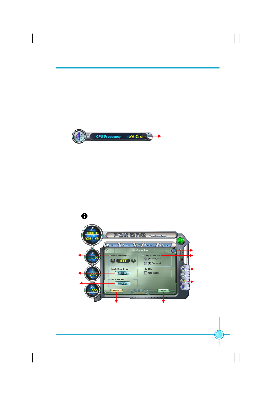
1. Main Page
Show CPU Information
34
Use the toolbar to navigate to
other pages
Alert Lamp
Switch Button
Skin Button
Exit
Minimum
Configuration
Homepage
Monitor Frequency/Voltage/Fan speed/Temperature value
Page 41
Chapter3 Directions for Bundled Software
Alert Lamp
When the system is in healthy status, the alert lamp color is green. When in
abnormal status, the color will turn red.
Switch Button
Click this button, it will simplify the window to HW monitor information bar as the
below figure shows. The bar could help you to monitor whether your system is in the
healthy status or not at any time.
Click here to return to
previous window
HW monitor information bar
Skin Button
Click this button, you will see the additive figures, such as “Crystal”and “Rock”.You
may select your favorite skin.
Configuration
This page allows you to select monitor interval time (ms) and temperature unit. It
also provides “Auto start up” function. Besides, click “Selection” to determine
which items will be shown in simple mode. In “F.I.S. Calibration”section, we
recommend you re-calibrate the CPU’s loading by clicking “calibration” button
after changing the CPU or memory modules, then restart the computer to apply
new setting. Attention: F.I.S. calibration function is optional.
Monitor
Interval
Selection
Calibration
Apply the changesResume default setting
Homepage
Click this button to visit Foxconn global English website.
Close
Temperature
Unit
Start Up
Configuration
35
Page 42

Chapter 3 Directions for Bundled Software
2. CPU Page - CPU Control
This page is used to select and run the CPU frequency to determine the current
performance level of the system. You can adjust the CPU frequency manually or
select “Auto Overclock”. Besides, it also provides “FOX Intelligent Stepping”, but
this function is optional.
Go to CPU page
Auto
Overclocking
Adjust manually
Select the different
benchmarks
Resume default setting
Apply the changes
3. Freq. Page - Frequency Control
In this page, you can set memory and PCIe frequency manually.
Note: The function of PCIe Frequency is optional.
Go to Freq. page
Select the option
Adjust manually
Resume default setting Apply the changes
36
Page 43

Chapter3 Directions for Bundled Software
4. Limit Setting page
This page includes five different sections. “CPU Temp.” and “Sys. Temp.” will help
you to set high limit temperature. “CPU Fan”, “Sys. Fan” and “FAN1 fan” are used
to set low limit rpm. All of them have alert function.
Go to Limit Setting page
Set high limit by dragging the lever
Show current CPU temperature value
Enable alert function
when the CPU
temperature is higher
than high limit value
Show current high
limit value of CPU
temperature
5. Voltage Page - Voltage Control (Optional)
This page allows you to set CPU, memory and North Bridge voltage manually.
Go to Voltage page
Select the option
Adjust manually
Resume default setting Apply the changes
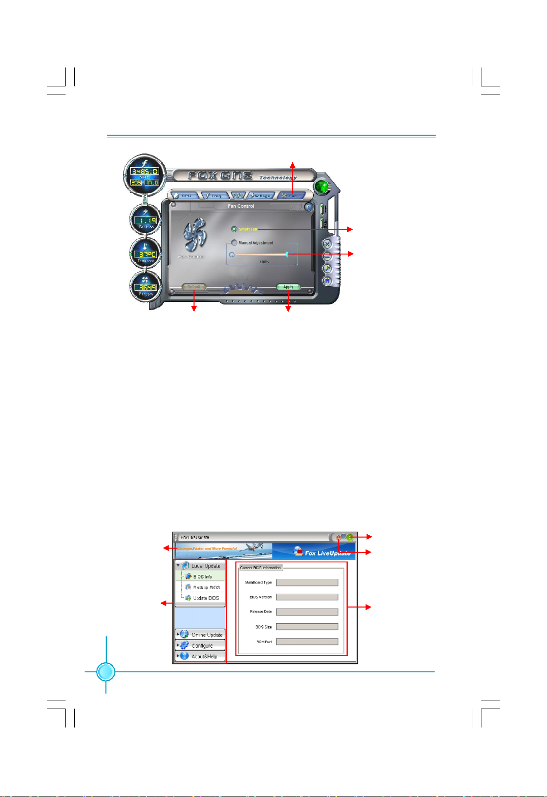
6. Fan Page - Fan Control
This page allows you to enable Smart Fan function and set fan speed manually.
37
Page 44
Chapter 3 Directions for Bundled Software
Go to Fan page
Enable or disable
smart fan function
Set fan speed by
dragging the lever
Apply the changesResume default setting
FOX LiveUpdate
FOX LiveUpdate is a useful utility to backup and update the system BIOS online
or locally. Drivers and utilities aslo can be updated online.
Supported Operating Systems:
-Windows 2000 -Windows 2003 (32-bit and 64-bit)
-Windows XP (32-bit and 64-bit) -Windows Vista (32-bit and 64-bit)
Using FOX LiveUpdate:
1. Local Update
“BIOS Info” tells you the system BIOS information; “Backup BIOS” could
backup your system BIOS, click this button ,then input a BIOS name and save
it; “Update BIOS” helps to update your system BIOS from local BIOS files,
please follow the request to finish the operation.
Exit
Link to website
Toolbar
38
Minimum
Show current
BIOS information
Page 45
Chapter3 Directions for Bundled Software
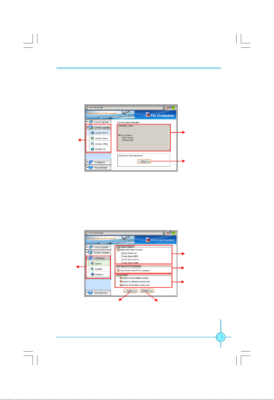
2. Online Update
This function enables you to update your system BIOS, Drivers, Utilities and all of
them from Internet. Click “start”, it will search for the new BIOS, Drivers and
Utilities from Internet. Then follow the request to finish the update operation.
Current
Click here
3. Configure
“Option” provides “auto search options”, “auto search Fox LiveUpdate” and
“version filter”. After setting “auto search options” and “auto search Fox
LiveUpdate”, the utility will work in the background and the related information
will show in a pop balloon notification and a dialogue box; click the “System”
button, you can set the backup BIOS location and select different kinds of skin
for the utility; “Advance” helps you to flash BIOS, boot Block and clear CMOS,
and we recommend you keep the default setting unchanged to avoid damage.
information
Search for new
BIOS, Drivers and
Utilities from Internet
Click here
Set auto
search options
Select to search
for the latest Fox
LiveUpdate
Select to search
for different kinds
of versions
Apply the changesResume default setting
39
Page 46

Chapter 3 Directions for Bundled Software
4. About & Help
This page shows some information about FOX LiveUpdate.
Information about
Click here
FOX LiveUpdate
FOX LOGO
FOX LOGO is a simple and useful utility to backup, change and delete the boot
Logo. The boot Logo is the image that appears on screen during the Power-On
Self-Tests (POST).
Supported Operating Systems:
-Windows 2000 -Windows 2003 (32-bit and 64-bit)
-Windows XP (32-bit and 64-bit) -Windows Vista (32-bit and 64-bit)
Using FOX LOGO:
Main Page
Main screen
Backup
Change
Delete
Warning:
When you change Logo or delete current Logo, the system will flash BIOS
file automatically. During this time, DO NOT shut down the system and the
application, or the motherboard would be damaged seriously.
40
Exit
Minimize
Website
About
Page 47
Chapter3 Directions for Bundled Software
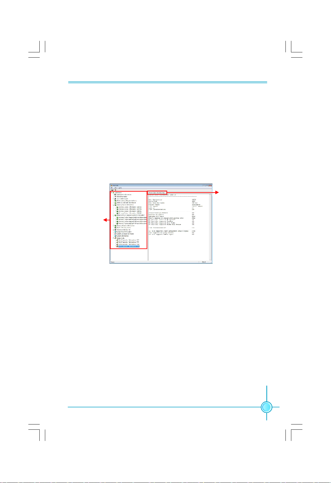
FOX DMI
FOX DMI is a full DMI information viewer, and it supports three kinds of DMI Data
format :Report, Data Fields and memory Dump.
Supported Operating Systems:
-Windows 2000 -Windows 2003 (32-bit and 64-bit)
-Windows XP (32-bit and 64-bit) -Windows Vista (32-bit and 64-bit)
Using FOX DMI:
Please operate this utility as the comments show.
Click here to select
the DMI Data format
Click here to
select the type
41
 Loading...