

Page 1

This manual is the intellectual property of FOXCONN, Inc. Although the
information in this manual may be changed or modified at any time,
FOXCONN does not obligate itself to inform the user of these changes.
Statement:
All trademarks are the property of their respective owners.
User’s Manual V1.0 in English for 915PL7AE series motherboard.
P/N:
91-181-915-A5-0E
Symbol description:
Note: refers to important information that can help you to use motherboard
better.
Attention: indicates that it may damage hardware or cause data loss,
and tells you how to avoid such problems.
Warning: means that a potential risk of property damage or physical
injury exists.
More information:
If you want more information about our products, please visit FOXCONN
website:
www.foxconnchannel.com
Version:
Trademark:
Page 2

Item Checklist:
Thanks for your purchasing FOXCONN 915PL7AE series motherboard. Please
check the package; if there are missing or damaged items, contact your distributor as soon as possible.
915PL7AE Series Motherboard (x1)
FOXCONN Utility CD (x1)
915PL7AE User Manual (x1)
RAID User Manual (x1) (optional)
IDE Ribbon Cable (x1)
FDD Ribbon Cable (x1)
I/O Shield (x1)
S-ATA Signal Cable (x2)
S-ATA Power Cable (x1)
RAID Floppy (x1) (optional)
Page 3

Declaration of conformity
HON HAI PRECISION INDUSTRY COMPANY LTD
66 , CHUNG SHAN RD., TU-CHENG INDUSTRIAL DISTRICT,
TAIPEI HSIEN, TAIWAN, R.O.C.
declares that the product
Motherboard
915PL7AE
is in conformity with
(reference to the specification under which conformity is declared in
accordance with 89/336 EEC-EMC Directive)
EN 55022:1998/A2:2003 Limits and methods of measurements of radio disturbance
characteristics of information technology equipment
EN 61000-3-2:2000 Electromagnetic compatibility (EMC)
Part 3: Limits
Section 2: Limits for harmonic current emissions
(equipment input current <= 16A per phase)
EN 55024-3-3/A1:2001 Electromagnetic compatibility (EMC)
Part 3: Limits
Section 2: Limits of voltage fluctuations and flicker in low-voltage
supply systems for equipment with rated current <= 16A
EN 55024:1998/A2:2003 Information technology equipment-Immunity characteristics limits
and methods of measurement
Signature : Place / Date : TAIPEI/2005
Printed Name : James Liang Position/ Title : Assistant President
Page 4

Declaration of conformity
Trade Name: FOXCONN
Model Name:
915PL7AE
Responsible Party: PCE Industry Inc.
Address: 458 E. Lambert Rd.
Fullerton, CA 92835
Telephone: 714-738-8868
Facsimile: 714-738-8838
Equipment Classification: FCC Class B Subassembly
Type of Product: Motherboard
Manufacturer: HON HAI PRECISION INDUSTRY
COMPANY LTD
Address: 66 , CHUNG SHAN RD., TU-CHENG
INDUSTRIAL DISTRICT, TAIPEI HSIEN,
TAIWAN, R.O.C.
Supplementary Information:
This device complies with Part 15 of the FCC Rules. Operation is subject to the
following two conditions : (1) this device may not cause harmful interference, and (2)
this device must accept any interference received, including interference that may
cause undesired operation.
Tested to comply with FCC standards.
Signature : Date : 2005
Page 5
Product Introduction
Installation Instructions
Supply ............................................................................................
BIOS Description
Standard CMOS Features .......................................................................... 31
BIOS Features ...........................................................................................
Advanced BIOS Features ..........................................................................
Advanced Chipset Features ......................................................................
Integrated Peripherals ................................................................................
Power Management Setup .........................................................................
PnP/PCI Configurations ...............................................................................
PC Health Status ........................................................................................
Load Fail-Safe Defaults .............................................................................
Load Optimized Defaults ............................................................................
Set Supervisor/User Password ................................................................. 51
Save & Exit Setup ......................................................................................
Exit Without Saving ....................................................................................
Table of Contents
Chapter
Chapter
Chapter
Driver CD Introduction
Utility CD content ........................................................................................ 54
Start to install drivers ................................................................................. 55
Chapter
Page 6

1. Attach the CPU and heatsink using silica gel to ensure full contact.
2. It is suggested to select high-quality, certified fans in order to avoid
damage to the motherboard and CPU due high temperatures.
3. Never turn on the machine if the CPU fan is not properly installed.
4. Ensure that the DC power supply is turned off before inserting or
removing expansion cards or other peripherals, especially when
you insert or remove a memory module. Failure to switch off the DC
power supply may result in serious damage to your system or
memory module.
Warning:
We cannot guarantee that your system will operate normally while
over-clocked. Normal operation depends on the over-clock capacity
of your device.
Warning:
Attention:
Since BIOS programs are upgraded from time to time, the BIOS
description in this manual is just for reference. We do not guarantee
that the content of this manual will remain consistent with the actual
BIOS version at any given time in the future.
Attention:
The pictures of objects used in this manual are just for your reference.
Please refer to the physical motherboard.
Page 7

This manual is suitable for motherboard of 915PL7AE
series. Each motherboard is carefully designed for the PC
user who wants diverse features.
-L with onboard 10/100M LAN
-K with onboard 1G LAN
-6 with 6-channel audio
-8 with 8-channel audio
-E with 1394 function
-S with SATA function
-R with RAID function
You can find PPID label on the motherboard. It indicates
the functions that the motherboard has.
For example:
On the blue mark of the PPID label, it means the
motherboard supports 6-channel audio(-6), 1394 port(-E),
onboard 10/100M LAN (-L), SATA function(-S).
Page 8
Chapter
Thank you for buying FOXCONN 915PL7AE series
motherboard. This series of motherboard is one of our new
products, and offers superior performance, reliability and
quality, at a reasonable price. This motherboard adopts the
advanced Intel® 915PL+ ICH6/ICH6R chipset, providing users
a computer platform with a high integration-compatibilityperformance price ratio.
This chapter includes the following information:
Main Features
Motherboard Layout
1
1
915PL7AE-Manual-EN-V1.0-01-25-04.p65 2005-5-26, 17:341
Page 9
Chapter 1 Product Introduction
2
Main Features
Size
ATX form factor of 12 inch x 8.6 inch
Microprocessor
Supports Intel® Pentium® 4 Prescott, Celeron D processors
Supports FSB at 533MHz/800MHz
Supports Hyper-Threading technology
Supports FSB Dynamic Bus Inversion (DBI)
Chipset
Intel® 915PL (North Bridge) + ICH6/6R (South Bridge)
System Memory
Two 184-pin DDR DIMM slots
Supports Dual-Channel DDR 400/333 DIMMs
Supports 128/256/512 Mb/1Gb DDR technology up to 2GB
USB 2.0 Ports
Supports hot plug
Eight USB 2.0 ports (four rear panel ports, two onboard USB connectors
providing four extra ports)
Supports wake-up from S1 and S3 mode
Supports USB 2.0 Protocol up to 480 Mbps transmission rate
Onboard Serial ATA (optional)
150 MBps transfer rate
Supports up to four S-ATA devices
Supports RAID 0, RAID 1, RAID 0+1, Matrix RAID (supported on ICH6R)
Onboard LAN (-L/-K) (optional)
Supports 10/100/1000 (-K optional) Mbit/sec Ethernet
LAN interface built-in on board
915PL7AE-Manual-EN-V1.0-01-25-04.p65 2005-5-26, 17:342
Page 10
3
Chapter 1 Product Introduction
Onboard 1394 (-E ) (optional)
Support hot plug
With rate of transmission at 400Mbps
Self-configured addressing
Can connect with 2 independent 1394 units synchronously at most
Onboard Audio (-6)(optional)
AC’97 2.3 Specification Compliant
Supports SPDIF output
Onboard Line-in jack, Line-out jack, Microphone jack
Supports 6-channel audio (setting via software)
Onboard Audio (-8)(optional)
Supports 8-channel audio
Supports SPDIF output
Supports Intel High Definition Audio
Supports high quality differential CD input
PCI Express x16 Support
Supports 4 GB/sec (8 GB/sec concurrent) bandwidth
Low power consumption and power management features
F.G.E. (Foxconn Graphics Extension) 8X Support
Compatible with AGP8X/4X specification
Supports Microsoft DirectX 9.0 standard
Green Function
Supports ACPI (Advanced Configuration and Power Interface)
Supports S0 (normal), S1 (power on suspend), S3 (suspend to RAM), S4
(Suspend to disk - depends on OS), and S5 (soft - off).
915PL7AE-Manual-EN-V1.0-01-25-04.p65 2005-5-26, 17:343
Page 11

Chapter 1 Product Introduction
4
Expansion Slots
Three PCI slots
One PCI Express x1 slot
One PCI Express x16 graphics slot
One F.G.E. slot
Advanced Features
PCI 2.3 specification compliant
Supports Windows 2000/XP soft-off
Supports Wake-on-Modem function (optional)
Supports PC Health function (capable of monitoring system voltage, CPU/
system temperature, and fan speed)
915PL7AE-Manual-EN-V1.0-01-25-04.p65 2005-5-26, 17:344
Page 12

5
Chapter 1 Product Introduction
Motherboard Layout
Note: The above motherboard layout is provided for reference only;
please refer to the physical motherboard.
ATA 100/66/33
915PL7AE-Manual-EN-V1.0-01-25-04.p65 2005-5-26, 17:345
Page 13

Chapter 1 Product Introduction
6
This chapter introduces the hardware installation process,
including the installation of the CPU, memory, power supply,
slots, rear panel and pin headers, and the mounting of
jumpers. Caution should be exercised during the installation
of these modules. Please refer to the motherboard layout
prior to any installation and read the contents in this chapter
carefully.
This chapter includes the following information:
CPU
Memory
Power supply
Rear Panel Connectors
Other Connectors
Expansion Slots
Jumpers
Chapter
2
2
915PL7AE-Manual-EN-V1.0-01-25-04.p65 2005-5-26, 17:346
Page 14

Chapter 2 Installation Instructions
7
Attention:
Take note of the following precautions before you install components
or change settings.
1. Use a grounded wrist strap or touch a safely grounded object,
such as an attached power supply, before handling components
to avoid damaging them due to static electricity.
2. Unplug the power cord before opening your chassis or touching
any component.
3. Hold components by their edges to avoid touching any exposed
integrated circuits (ICs).
4. Whenever you uninstall a component, place it on a grounded
anti-static pad or into the anti-static bag that it came in.
915PL7AE-Manual-EN-V1.0-01-25-04.p65 2005-5-26, 17:347
Page 15
Chapter 2 Installation Instructions
8
CPU
This motherboard supports single Pentium® 4 Processor including Prescott,
Celeron D processor in an LGA775 package.
It also supports Hyper-Thread-
ing Technology and FSB Dynamic Bus Inversion (DBI).
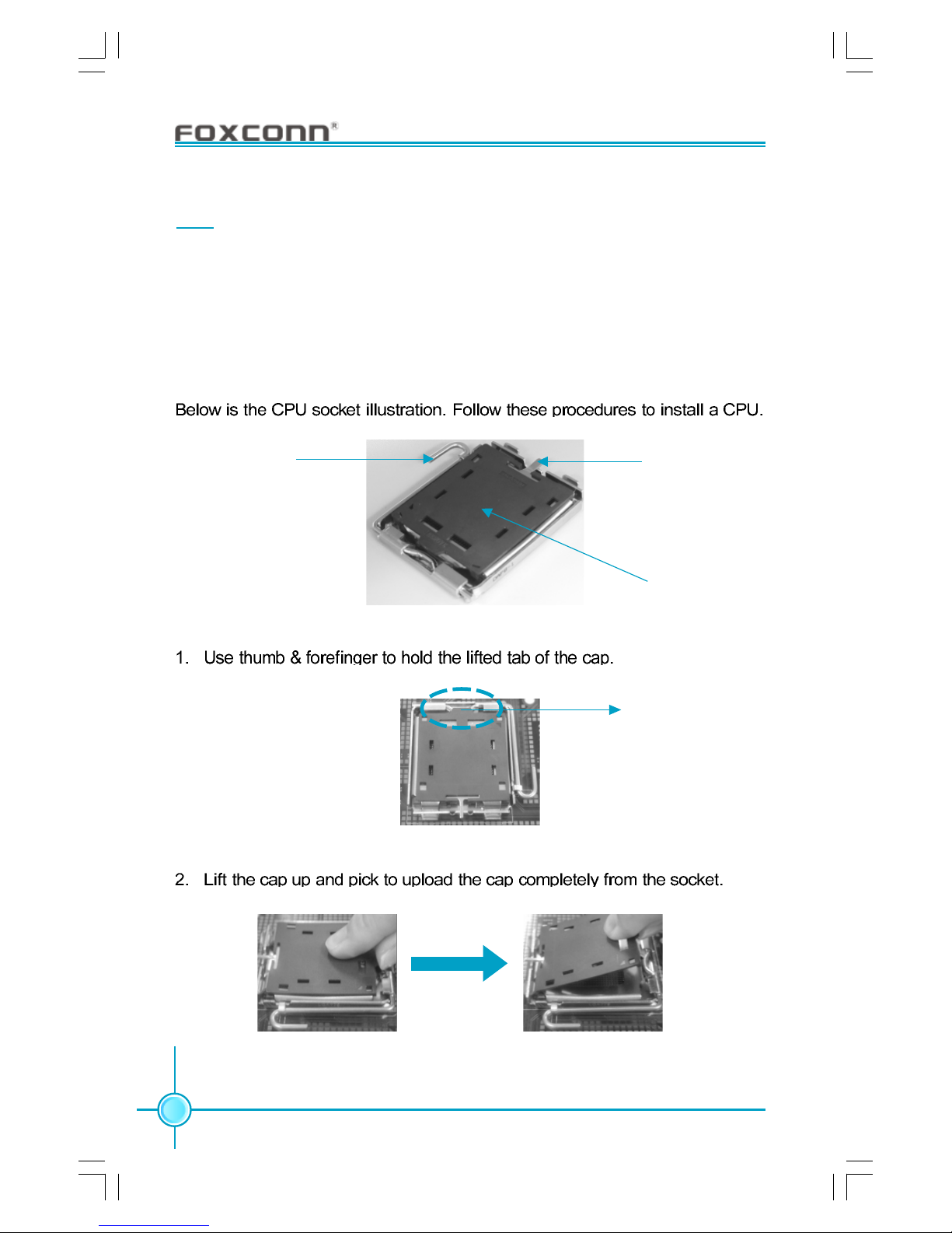
Installation of CPU
Load lever
Load plate
Load cap
Lifted tab
915PL7AE-Manual-EN-V1.0-01-25-04.p65 2005-5-26, 17:348
Page 16
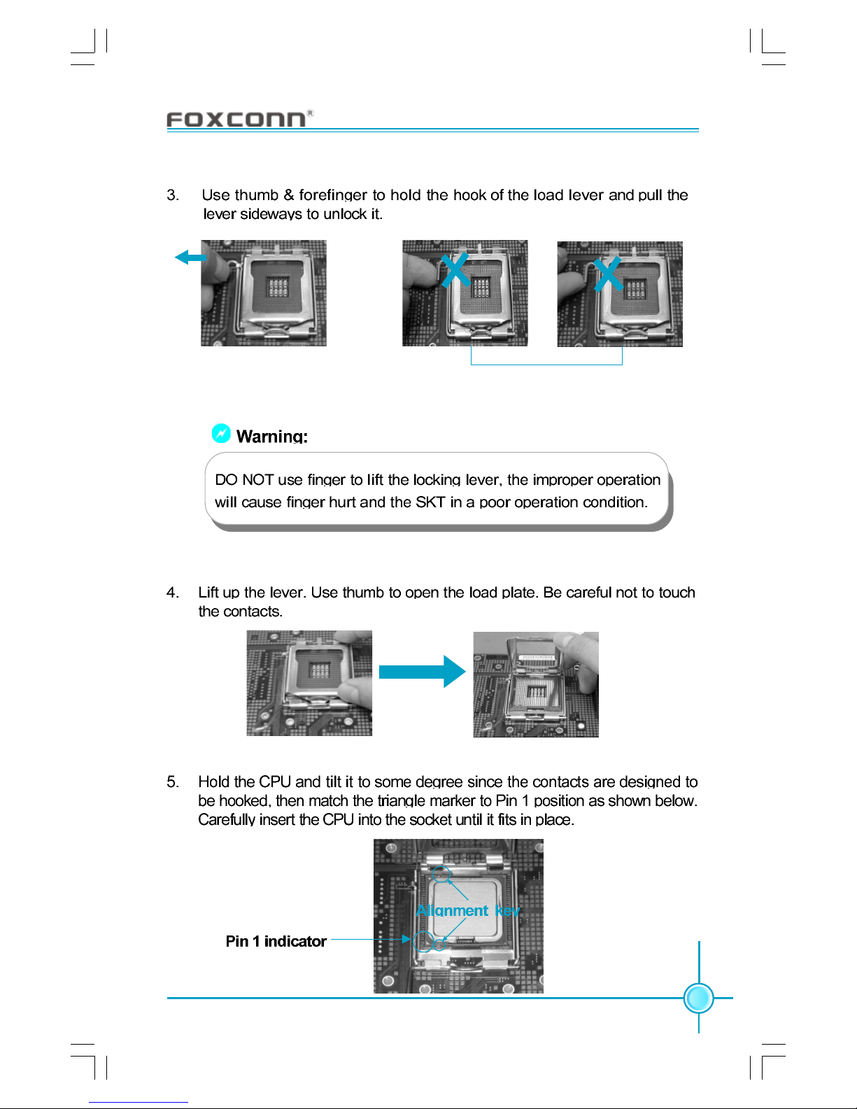
Chapter 2 Installation Instructions
9
Correct Wrong
915PL7AE-Manual-EN-V1.0-01-25-04.p65 2005-5-26, 17:349
Page 17

Chapter 2 Installation Instructions
10
Warning:
Excessive temperatures will severely damage the CPU and
system. Therefore, you should install CPU cooling fan and make
sure that the cooling fan works normally at all times in order to
prevent overheating and damaging to the CPU. Please refer to your
CPU fan user guide to install it properly.
915PL7AE-Manual-EN-V1.0-01-25-04.p65 2005-5-26, 17:3410
Page 18
Chapter 2 Installation Instructions
11
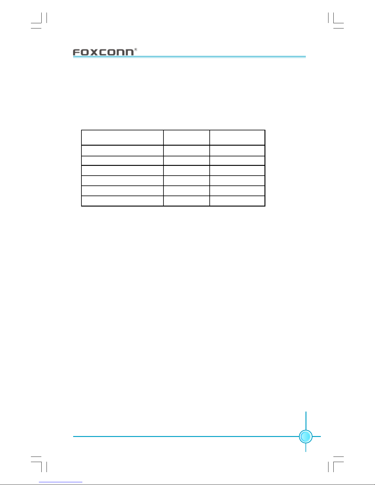
Qualified CPU Vendor List
The following table lists the CPUs that have been tested and qualified for use
with this motherboard.
Intel
®
Celeron®D
Intel
®
Celeron®D
Intel
®
Pentium®4
Intel
®
Pentium®4
Intel
®
Pentium®4
Intel
®
Pentium®4
Processor Name
3.06G
2.93G
2.80G
3.0G
3.20G
3.40G
FSB(MHz)
533MHz
533MHz
800MHz
800MHz
800MHz
800MHz
Clock Speed
915PL7AE-Manual-EN-V1.0-01-25-04.p65 2005-5-26, 17:3411
Page 19
Chapter 2 Installation Instructions
12
Memory
This motherboard accomodates two 184-pin DDR slots. These slots support
128Mb, 256 Mb, 512 Mb and 1 Gb DDR technologies for x8 and x16 devices. You
must install at least one memory bank to ensure normal operation.
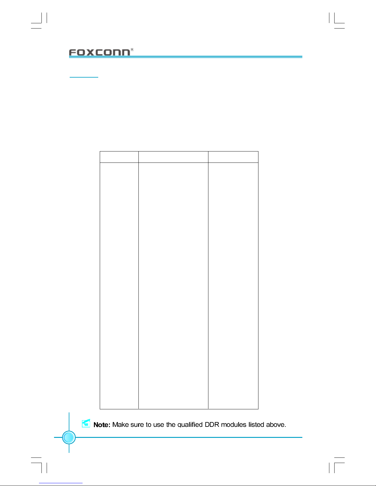
Qualified DDR Memory Vendor List
The following table lists the memory modules that have been tested and
qualified for use on this motherboard.
APACER DDR333 256MB
APACER DDR400 256MB
CORSAIR DDR400 512MB
CORSAIR DDR466 256MB
CORSAIR DDR500 256MB
CRL DDR333 512MB
CROTALUS DDR400 512MB
GEIL DDR400 512MB
HYNIX DDR333 128MB
HYNIX DDR400 128MB
INFINEON DDR333 128MB
INFINEON DDR400 128MB
INFINEON DDR400 256MB
KINGMAX DDR400 256MB
KINGMAX DDR400 512MB
KINGSTEK DDR333 512MB
KINGSTEK DDR400 512MB
KINGSTON DDR400 256MB
KINGSTON DDR400 512MB
LPT DDR500 256MB
MT DDR333 128MB
MT DDR333 256MB
MT DDR333 512MB
NANYA DDR333 512MB
NANYA DDR333 1GB
SAMSUNG DDR333 128MB
SAMSUNG DDR333 256MB
SAMSUNG DDR333 512MB
SAMSUNG DDR400 128MB
SAMSUNG DDR400 256MB
TWINMOS DDR400 1GB
Vendor
Type Size
915PL7AE-Manual-EN-V1.0-01-25-04.p65 2005-5-26, 17:3412
Page 20

Chapter 2 Installation Instructions
13
Installation of DDR Memory
1. There is only one gap in the middle of the DIMM slot, and the memory
module can be fixed in one direction only. Unlock a DIMM slot by pressing the
module clips outward.
2. Align the memory module to the DIMM slot, and insert the module vertically
into the DIMM slot.
3. The plastic clips at both sides of the DIMM slot will lock automatically.
Warning :
104 Pins
80 Pins
Be sure to unplug the AC power supply before adding or removing
expansion cards or other system peripherals, especially the
memory devices, otherwise your motherboard or the system
memory might be seriously damaged.
915PL7AE-Manual-EN-V1.0-01-25-04.p65 2005-5-26, 17:3413
Page 21

Chapter 2 Installation Instructions
14
Power Supply
This motherboard uses an ATX power supply. In order to avoid damaging any
devices, make sure that they have been installed properly prior to connecting
the power supply.
Note: We strongly recommended you use 24pin power supply. If you want to use 20-pin power
supply, you need to align the ATX power connector according to the right picture.
align the connector
24
24-pin ATX power connector
13
+3.3V
-12V
RSVD
+5V
GND GND
GND
PSON
+5V
GND
+12V
GND
+5V_AUX +5V
+12V
1
GND
+5V
+3.3V
GND
GND
+5V
12
PWROK
4-pin ATX_12V power connector
1 2V
GND
12V
3
1
4
2
GND
4-pin ATX_12V Power Connector: PWR2
The ATX power supply connects to PWR2 and
provides power to the CPU.
24-pin ATX power connector: PWR1
PWR1 is the ATX power supply connector. Make
sure that the power supply cable and pins are
properly aligned with the connector on the
motherboard. Firmly plug the power supply cable
into the connector and make sure it is secure.
915PL7AE-Manual-EN-V1.0-01-25-04.p65 2005-5-26, 17:3414
Page 22

Chapter 2 Installation Instructions
15
Rear Panel Connectors
This motherboard provides the ports as below:
For -6 models (optional)
For -8 models (optional)
Rear
LFE/CEN
Microphone
Line-in
Line-out
Side
10
USB 2.0 Ports
PS/2 Mouse
Connector
Parallel Port
(Printer Port)
LAN Port (optional)
3
7
8
1394 Port
(optional)
6
PS/2 Keyboard
Connector
Serial Port
(COM1)
3
9
1
2
4
Line-in
Line-out
Microphone
5
SPDIF
Coaxial Out
Port
PS/2 Mouse Connector
This green 6-pin connector is for a PS/2 mouse.
PS/2 Keyboard Connector
This purple 6-pin connector is for a PS/2 keyboard.
Serial Port (COM1)
This 9-pin COM1 port is for pointing devices or other serial devices.
Parallel Port (Printer Port)
This 25-pin port connects a parallel printer, a scanner, or other devices.
1
2
3
4
SPDIF Coaxial Out Port
This port connects to external audio output devices with coaxial cable connectors.
5
915PL7AE-Manual-EN-V1.0-01-25-04.p65 2005-5-26, 17:3515
Page 23

Chapter 2 Installation Instructions
16
1394 Port (optional)
This digital interface supports electronic devices such as digital cameras,
scanners, and printers.
USB 2.0 Ports
These four Universal Serial Bus (USB) ports are available for connecting USB
2.0/1.1 devices.
LAN Port (optional)
This port allows connection to a Local Area Network (LAN) through a network hub.
8
6
7
Line-in, Line-out, Microphone Jacks (for -6 models)
When using a 2-channel sound source, the Line-out jack is used to connect to
speaker or headphone; the Line-in jack connects to an external CD player, tape
player or other audio device. The Microphone jack is used to connect to the
microphone.
When using a 6-channel sound source, connect the front speaker to the green
audio output; connect the surround sound speaker to the blue audio output;
connect the center speaker/subwoofer to the red Microphone output.
Line-in, Line-out, Microphone, Rear, LEF/CEN, Side Jacks (for -8 models)
When using an 8-channel sound source, connect the front speaker to the green
audio output; connect the rear sound speaker to the black audio output; connect the center speaker/subwoofer to the orange audio output; connect the side
sound speaker to the grey audio output.
9
10
915PL7AE-Manual-EN-V1.0-01-25-04.p65 2005-5-26, 17:3516
Page 24

Chapter 2 Installation Instructions
17
Other Connectors
This motherboard includes connectors for floppy devices, IDE devices,serial
ATA devices, USB devices, IR module, and others.
FDD connector: FLOPPY
This motherboard includes a standard FDD connector, supporting 360 K, 720
K, 1.2 M, 1.44 M, and 2.88 M FDDs.
HDD connector: PIDE
This motherboard includes one Ultra DMA 100/66/33 IDE connector. We suggest you connect the cable’s blue connector to the IDE connector, then connect
the black connector to the master device and connect the grey connector to the
slave device. If you intend to install two hard disks, you must configure the
second drive as a slave device by setting the jumper accordingly. For details,
please refer to the hard disk documentation for the jumper settings.
Front Panel Connector: FP1
This motherboard includes one connector for connecting the front panel switch
and LED indicators.
IDE LED Connector (HD-LED)
The connector connects to the case’s IDE indicator LED indicating the activity
status of hard disks.
Reset Switch (RESET)
Attach the connector to the Reset switch on the front panel of the case; the
system will restart when the switch is pressed.
FP1
NC
HD-LED
RESET
PWRLED PWRSW
+ -
1
+ -
915PL7AE-Manual-EN-V1.0-01-25-04.p65 2005-5-26, 17:3517
Page 25

Chapter 2 Installation Instructions
18
Fan Connectors: CPU_FAN, FAN1
Connect the CPU fan cable, chassis fan cable to the CPU_FAN and FAN1 connectors respectively. The fan speed of CPU_FAN and SYS_FAN can be detected
and viewed in “PC Health Status” section of the CMOS Setup. These fans will be
automatically turned off after the system enters S3, S4 and S5 mode.
Audio Connectors: CD_IN, AUX_IN (optional)
CD_IN, AUX_IN are Sony standard CD audio connectors, they can be connected
to a CD-ROM drive through a CD audio cable.
FAN1
SENSE
+12V
GND
1
CD_IN
CD_L
GND
CD_R
AUX_IN (optional)
AUX_R
AUX_L
GND
Power LED Connector (PWRLED)
Attach the connector to the power LED on the front panel of the case. The Power
LED indicates the system’s status. When the system is in S0 status, the LED is
on. When the system is in S1 status, the LED is blink; When the system is in S3,
S4, S5 status, the LED is off.
Power Switch Connector (PWRSW)
Attach the connector to the power button of the case. Pushing this switch allows
the system to be turned on and off rather than using the power supply button.
CPU_FAN
POWER
GND
1
SENSE
CONTROL
915PL7AE-Manual-EN-V1.0-01-25-04.p65 2005-5-26, 17:3518
Page 26

Chapter 2 Installation Instructions
19
Wake-Up On Internal Modem (optional): WOM
Through this function, the system which is in suspend
or soft-off status can be waken up by a ring signal received from the internal modem. When this function is
enabled, make sure an internal modem card which
supports this function is used. Connect the header to
the relevant connector on the modem card, set “Power
On by Ring” as “Enabled” in the “Power Management
Setup” of the CMOS Setup Utility. Save and exit, then
boot the operating system once to make sure this function takes effect.
+5V _SB
GND
WOM
1
Modem wake up
S-ATA Connectors (optional): SATA_1, SATA_2, SATA_3, SATA_4
The S-ATA connector is used to connect the S-ATA device to the motherboard. These connectors support the
thin Serial ATA cables for primary internal storage
devices. The current Serial ATA interface allows up to
150MB/s data transfer rate.
SATA _1/SATA _2/
SATA _3/SATA _4
GND
GND
GND
TX+
TX-
RX+
RX-
1
1394 Connector (optional): F_1394
The 1394 expansion cable can be connected to either
the front (provided that the front panel of your chassis
is equipped with the appropriate interface) or rear
panel of the chassis.
IrDA Connector: IR
This connector supports wireless transmitting and receiving device. Before using this function, configure the
settings of IR Mode from the “Integrated Peripherals”
section of the CMOS Setup.
+12V
GND
TPB -
TPA -
F_1394
1
2
910
+12V
TPB +
GND
Empty
TPA +
1
IR
+5V
GND
IRRX
IRTX
Empty
915PL7AE-Manual-EN-V1.0-01-25-04.p65 2005-5-26, 17:3519
Page 27

Chapter 2 Installation Instructions
20
Front Audio Connector: F_AUDIO
For -6 models (optional)
The audio connector provides two kinds of audio output choices: the Front Audio,
the Rear Audio. Their priority is sequenced from high to low (Front Audio to Rear
Audio). If headphones are plugged into the front panel of the chassis (using the
Front Audio), then the Line-out (Rear Audio) on the rear panel will not work. If you
do not want to use the Front Audio, pin 5 and 6, pin9 and 10 must be SHORT,
and then the signal will be sent to the rear audio port.
For -8 models (optional)
The audio connector provides two kinds of audio output choices: the Front Audio,
the Rear Audio. Front Audio supports re-tasking function. Their priority is the
same.
F_AUDIO (for -8 models)
F_AUDIO (for -6 models)
1
PORT2_L
SENSE_SEND
PORT1_L
PORT1_R
PORT2_R
AUD_GND
PRESENCEJ
SENSE1_RETURN
Empty
SENSE2_RETURN
1
AUD_OUT-L
NA
MIC_IN
MIC_PWR
AUD_OUT-R
MIC_GND
+5VA
AUD_RET-R
Empty
AUD_RET-L
USB Connectors: F_USB1, F_USB2
Besides four USB ports on the rear panel, the series of motherboards also
have two 10-pin connectors on board which may connect to front panel USB
cable(optional) to provide additional four USB ports.
F_USB 2
D7-
VCC
D6+
D6-
Empty
GND
NC
VCC
GND
D7+
F_USB 1
D5-
VCC
D4+
D4-
Empty
GND
NC
VCC
GND
D5+
915PL7AE-Manual-EN-V1.0-01-25-04.p65 2005-5-26, 17:3520
Page 28

Chapter 2 Installation Instructions
21
Chassis Intruder Connector: INTR
The connector connects to the chassis security switch
on the case. The system can detect the chassis intrusion through the status of this connector. If the connector has been closed once, the system will send a
message. To utilize this function, set
“Case Open
Warning” to “Enabled” in the “Power Management
Setup” section of the CMOS Setup. Save and exit, then
boot the operating system once to make sure this
function takes effect.
SP
The out connector is capable of providing digital audio to external speak-ers or compressed AC3
data to an external Dolby digital decoder.
Note:The empty pin of SPDIF cable should be aligned
to empty pin of S/PDIF out connector.
Speaker Connector: SPEAKER
The speaker connector is used to connect speaker
of the chassis.
SPEAKER
SPDIF_OUT
SPDIF_OUT
+5V
GND
Empty
INTR
1
2
INTRUDERJ
GND
SPK(Pull high)
SPKJ
Empty
NC
Addtional COM : COM2
This motherboard provides an additional serial COM
header for your machine.
Connect one side of a switching cable to the header,
then attach the serial COM device to the other side of
the cable.
COM2
SOUT
GND
RI
DTR
DSR
SIN
CTS
RTS
Empty
9
10
1
2
915PL7AE-Manual-EN-V1.0-01-25-04.p65 2005-5-26, 17:3521
Page 29

Chapter 2 Installation Instructions
22
Expansion Slots
This motherboard includes three 32-bit Master PCI bus slots, one PCI Express
x1 slot, one PCI Express x16 slot and one F.G.E.(Foxconn Graphics Extension)
slot.
PCI Slots
The expansion card can be installed in the PCI slot. When you install or take out
such card, you must make sure that the power plug has been pulled out.
Please carefully read the instructions provided for such card, and install and set
the necessary hardware and software for such card, such as the jumper or
BIOS setup.
F.G.E. Slot
The F.G.E.(Foxconn Graphics Extension) slot is a special design that provides
an extended graphics interface for AGP8/4X VGA cards.
The following table lists the AGP VGA cards that have been tested and qualified on F.G.E.8X slot.
Qualified AGP VGA Cards Vendor List
Memory Model Name
Graphics
Chip Vendor
Speed
ATI RADEON 9200 SE 64MB 8X
ELSA GEFORCE 2MX/MX400 32M 4X
MSI GEFORCE TI4200TD 128MB 8X
MSI GEFORCE FX5200 Ultra 128MB 8X
NVIDIA GEFORCE FX5200 256MB 8X
NVIDIA GEFORCE 4 MX4000 128MB 8X
NVIDIA GEFORCE FX5700 128MB 8X
NVIDIA GEFORCE6800LE 128MB 8X
NVIDIA GEFORCE FX 5200 128MB 8X
NVIDIA GEFORCE FX5950Ultra 256MB 8X
WINFAST GEFORCE6800GT 256MB 8X
915PL7AE-Manual-EN-V1.0-01-25-04.p65 2005-5-26, 17:3522
Page 30

Chapter 2 Installation Instructions
23
PCI Express Slots
PCI Express will offer the following design advantages over the PCI and AGP
interface:
-Compatible with existing PCI drivers and software and Operating Systems.
-High Bandwidth per Pin. Low overhead. Low latency.
-PCI Express supports a raw bit-rate of 2.5 Gb/s on the data pins. This
results in a real bandwidth per pair of 250 MB/s.
-A point to point connection, allows each device to have a dedicated connection without sharing bandwidth.
-Ability to comprehend different data structure.
-Low power consumption and power management features.
PCI Express will take two forms, x16 and x1 PCI Express slots. Whereas the x16
slot is reserved for graphic/video cards, the x1 slots are designed to accommodate less bandwidth-intensive cards, such as a modem or LAN card.
The difference in bandwidth between the x16 and x1 slots are not able to be
sure, with the x16 slot pushing 4GB/sec (8GB/sec concurrent) of bandwidth,
and the x1 PCI Express slot offering 250 MB/sec.
Installing an expansion card
1. Before installing the expansion card, please make sure that the power supply is switched off or the power cord is unplugged. Please read the documentation that came with it and make the necessary hardware settings for
the card.
2. Remove the bracket facing the slot that you intend to use. Keep the screws
for later use.
3. Align the card connector with the slot and press firmly until the card is
completely seated on the slot.
4. Secure the card to the chassis with the screw you removed earlier.
If a performance graphics card was installed into x16 PCI
Express slot, 2X12 pin power supply was strongly recommended since that card may be drawn 75W power.
Note:
915PL7AE-Manual-EN-V1.0-01-25-04.p65 2005-5-26, 17:3523
Page 31

Chapter 2 Installation Instructions
24
Qualified PCI Express x16 Graphics Cards Vendor List
The following table lists the PCI Express x16 graphics cards that have been
tested and qualified for use with this motherboard.
Memory
Model Name
Graphics Chip
Vendor
ATI RADEON X300SE 128MB
ATI RADEON X800SE 128MB
ATI RADEON X300SE 256MB
WINFAST GEFORCE 6200 128MB
WINFAST NVIDIA GEFORCE X6600 128MB
WINFAST GEFORCEPCX5750 256MB
ASUS RADEON X600PRO 128MB
NVIDIA GEFORCE PCX5750 128MB
EVGA GEFORCE 6200 256MB
DOOM GEFORCE X6600 128MB
ARX GEFORCE X6600 128MB
915PL7AE-Manual-EN-V1.0-01-25-04.p65 2005-5-26, 17:3524
Page 32

Chapter 2 Installation Instructions
25
Jumpers
The users can change the jumper settings on this motherboard if needed. This
section explains how to use the various functions of this motherboard by changing the jumper settings. Users should read the following contents carefully prior
to modifying any jumper settings.
Description of Jumpers
1.For the jumpers on this motherboard, pin 1 can be identified by the silkscreen
printed “
” next to it. However, in this manual, pin 1 is simply labeled as “1”.
2.The following table provides some explanation of the jumper pin settings.
User should refer to this when adjusting jumper settings.
Jumper Diagram Definition Description
1-2 Set pin1 and pin2 closed
2-3 Set pin2 and pin3 closed
Closed Set the pin closed
Open Set the pin opened
1
1
1
1
1
Clear CMOS Jumper: CLS_CMOS
This motherboard uses the CMOS RAM to store all the
set parameters. The CMOS can be cleared by removing the CMOS jumper.
How to clear CMOS?
1.Turn off the AC power supply and connect pins 1
and 2 together using the jumper cap.
2.Return the jumper setting to the default setting (pins 2
and 3 together with the jumper cap).
3.Turn the AC power supply back on.
Normal
(Default)
CLS_CMOS
Clear
1
3
2
1
3
2
Warning:
1. Disconnect the power cable before adjusting the jumper settings.
2. Do not clear the CMOS while the system is turned on.
915PL7AE-Manual-EN-V1.0-01-25-04.p65 2005-5-26, 17:3525
Page 33

Chapter 2 Installation Instructions
26
BIOS TBL Jumper: JP3
The system cannot boot, if the BIOS failed to be flashed
in conventional flash BIOS process. But you will have
no such worry when using the BIOS TBL function, which
is used to protect BIOS “Top Boot Block”. By using this
function, the system still can boot even if the BIOS fails
to flash. To utilize this function, you can short pin 1 and
2 with the jumper cap.
BIOS TBL
Enable
BIOS TBL
Disable
JP3
915PL7AE-Manual-EN-V1.0-01-25-04.p65 2005-5-26, 17:3526
Page 34

Chapter 2 Installation Instructions
27
Starting up for the first time
1. After making all the connections, replace the system case cover.
2. Be sure that all switches are off.
3. Turn on the devices in the following order.
a. Monitor
b. External SCSI devices (starting with the last device on the chain)
c. System power
4. After applying power LED on the system, front panel case lights up. For ATX
power supplies, the system LED lights up when you press the ATX power
switch. If your monitor complies with green standards or if it has a power
standby feature, the monitor LED may light up or switch between orange
and green after the system LED turns on. The system then runs the poweron tests. While the tests are running, the BIOS beeps or additional
messages appear on the screen. If you do not see anything within 30
seconds from the time you turned on the power, the system may have failed
a power-on test. Check the jumper settings and connections or call your
retailer for assistance.
5. At power on, hold down <Delete> to enter BIOS Setup. Follow the instructions
in Chapter 3.
Powering off the computer
1. Using the OS shut down function
If you use windows 2000/XP, click the start button, click Shut Down, then click
the OK button to shut down the computer. The power supply should turn off after
Windows shuts down.
2.Using the dual function power switch
While the system is ON, pressing the power switch for less than 4 seconds puts
the system to sleep mode or to soft-off mode, depending on the BIOS setting.
Pressing the power switch for more than 4 seconds lets the system enter the
soft-off mode regardless of the BIOS setting.
915PL7AE-Manual-EN-V1.0-01-25-04.p65 2005-5-26, 17:3527
Page 35

Appendix
28
This chapter tells how to change system settings through
the BIOS Setup menus. Detailed descriptions of the BIOS
parameters are also provided.
You have to run the Setup Program when the following cases
occur:
1. An error message appears on the screen during the system
POST process.
2. You want to change the default CMOS settings.
This chapter includes the following information:
Enter BIOS Setup
Main Menu
Standard CMOS Features
BIOS Features
Advanced BIOS Features
Advanced Chipset Features
Integrated Peripherals
Power Management Setup
PnP/PCI Configurations
PC Health Status
Load Fail-Safe Defaults
Load Optimized Defaults
Set Supervisor/User Password
Save & Exit Setup
Exit Without Saving
Chapter
3
3
915PL7AE-Manual-EN-V1.0-01-25-04.p65 2005-5-26, 17:3528
Page 36

Chapter 3 BIOS Description
29
Enter BIOS Setup
The BIOS is the communication bridge between hardware and software,
correctly setting up the BIOS parameters is critical to maintain optimal system
performance. Power on the computer, when the following message briefly
appears at the bottom of the screen during the POST (Power On Self Test),
press <Del> key to enter the AWARD BIOS CMOS Setup Utility.
Press TAB to show POST screen, DEL to enter SETUP.
Main Menu
The main menu allows you to select from the list of setup functions and two exit
choices. Use the arrow keys to select among the items and press <Enter> to
accept or go to the sub-menu.
The items in the main menu are explained below:
Standard CMOS Features
The basic system configuration can be set up through this menu.
BIOS Features
The special features can be set up through this menu.
Main Menu
Note:
We do not suggest that you change the default parameters in the
BIOS Setup, and we shall not be responsible for any damage that
result from any changes that you make.
915PL7AE-Manual-EN-V1.0-01-25-04.p65 2005-5-26, 17:3529
Page 37

Chapter 3 BIOS Description
30
Advanced BIOS Features
The advanced system features can be set up through this menu.
Advanced Chipset Features
The values for the chipset can be changed through this menu, and the
system performance can be optimized.
Integrated Peripherals
Onboard peripherals can be set up through this menu.
Power Management Setup
All the items of Green function features can be set up through this menu.
PnP/PCI Configurations
The system’s PnP/PCI settings and parameters can be modified through
this menu.
PC Health Status
This will display the current status of your PC.
Load Fail-Safe Defaults
The fail-safe default BIOS settings can be loaded through this menu.
Load Optimized Defaults
The optimal performance settings can be loaded through this menu,
however, the stable default values may be affected.
Set Supervisor/User Password
The supervisor/user password can be set up through this menu.
Save & Exit Setup
Save CMOS value settings to CMOS and exit setup.
Exit Without Saving
Abandon all CMOS value changes and exit setup.
915PL7AE-Manual-EN-V1.0-01-25-04.p65 2005-5-26, 17:3530
Page 38

Chapter 3 BIOS Description
31
Standard CMOS Features
This sub-menu is used to set up the standard CMOS features, such as the date,
time, HDD model and so on. Use the arrow keys to select the item and set up,
and then use the <PgUp> or <PgDn> keys to choose the setting values.
Date
This option allows you to set the desired date (usually as the current date)
with the <day><month><date><year> format.
Day—weekday from Sun. to Sat., defined by BIOS (read-only).
Month—month from Jan. to Dec..
Date—date from 1
st
to 31st, can be changed using the keyboard.
Year—year, set up by users.
Time
This option allows you to set up the desired time (usually as the current time)
with <hour><minute><second> format.
IDE Channel 0/1/2 Master/Slave
These categories identify the HDD types of 1 IDE channel installed in the computer system. There are three choices provided for the Enhanced IDE BIOS:
None, Auto, and Manual. “None” means no HDD is installed or set; “Auto” means
the system can auto-detect the hard disk when booting up; by choosing “Manual”
and changing Access Mode to “CHS”, the related information should be entered
manually. Enter the information directly from the keyboard and press < Enter>:
Standard CMOS Features Menu
Cylinder number of cylinders Head number of heads
Precomp write pre-compensation Landing Zone landing zone
Sector number of sectors
915PL7AE-Manual-EN-V1.0-01-25-04.p65 2005-5-26, 17:3531
Page 39

Chapter 3 BIOS Description
32
Award (Phoenix) BIOS can support 3 HDD modes: CHS, LBA and Large or read
Auto mode.
CHS For HDD<528MB
LBA For HDD>528MB & supporting LBA (Logical Block Addressing)
Large For HDD>528MB but not supporting LBA
Auto Recommended mode
Drive A/B
This option allows you to select the kind of FDD to be installed, including [None],
[360K, 5.25 in], [1.2M, 5.25 in], [720K, 3.5 in], [1.44M, 3.5 in] and [2.88 M, 3.5 in].
Video
The following table is provided for your reference in setting the display mode for
your system.
EGA/VGA Enhanced Graphics Adapter / Video Graphic Array. For EGA,
VGA, SEGA, SVGA, or PGA monitor adapters.
CGA 40 Color Graphic Adapter, powering up in 40 column mode.
CGA 80 Color Graphic Adapter, powering up in 80 column mode.
MONO Monochrome adapter, including high resolution monochrome adapters.
Halt On
This category determines whether or not the computer will stop if an error is
detected during powering up.
All Errors Whenever the BIOS detects a nonfatal error, the system
will stop and you will be prompted.
No Errors The system boot will not stop for any errors that may
be detected.
All, But Keyboard The system boot will not stop for a keyboard error; but
it will stop for all other errors.
All, But Diskette The system boot will not stop for a diskette error; but it will
stop for all other errors.
All, But Disk/Key The system boot will not stop for a keyboard or disk
error, but it will stop for all other errors.
915PL7AE-Manual-EN-V1.0-01-25-04.p65 2005-5-26, 17:3532
Page 40

Chapter 3 BIOS Description
33
Memory
This is a Display-Only Category, determined by POST (Power On Self Test) of
the BIOS.
Base Memory The BIOS POST will determine the amount of base (or
conventional) memory installed in the system.
Extended Memory The BIOS determines how much extended memory is
present during the POST.
Total Memory Total memory of the system.
915PL7AE-Manual-EN-V1.0-01-25-04.p65 2005-5-26, 17:3533
Page 41

Chapter 3 BIOS Description
34
BIOS Features
[SuperBoot] SuperBoot (Default: Disabled)
SuperBoot allows system-relevant information to be stored in CMOS upon the
first normal start-up of your PC, and the relevant parameters will be restored
to help the system start up more quickly on each subsequent start-up. The
available setting values are: Disabled and Enabled.
[SuperBIOS-Protect] SuperBIOS-Protect (Default: Disabled)
SuperBIOS-Protect function protects your PC from viruses, e.g. CIH. The
available setting values are: Disabled and Enabled.
[SuperRecovery] SuperRecovery Hotkey (Default: LSHIFT+F12)
SuperRecovery provides the users with an excellent data protection and HDD
recovery function. There are 12 optional hotkeys and the default hotkey is
LSHIFT+F12.
[SuperSpeed] SuperSpeed
Press <Enter> to set the items of SuperSpeed. Setting these items are good
for overclocking. Please refer to page 35.
BIOS Features Menu
Warning:
Be sure your selection is right. Overclocking will be dangerous!
We will not be responsible for any damage caused.
915PL7AE-Manual-EN-V1.0-01-25-04.p65 2005-5-26, 17:3534
Page 42

Chapter 3 BIOS Description
35
Auto Detect PCI Clk (Default: Enabled)
This option is used to set whether the clock of an unused PCI slot will be
disabled to reduce electromagnetic interference.
Spread Spectrum (Default: Disabled)
If you enable spread spectrum, it can significantly reduce the EMI (ElectroMagnetic Interference) generated by the system.
CPU Clock Ratio (Default: Depend on CPU )
This option is used to set the ratio of an unlocked CPU.
Overclock (Default: Default)
This option is used to configure the overclocking and performance setting.
The available setting value are: Default, Manual, Optimal Reference.
1). “Default” indicates non-overclocking.
2). If “Manual” is selected, the following options will be activated and user can
set it personally;
System Memory Frequency (Default: Auto)
This option is used to set system memory frequency.
CPU Clock (Default: Depend on CPU)
This option is used to set CPU clock.
PCI Express Clock (Default: 100)
This option is used to set PCI Express clock.
PCI Bus Clock (Default: 33.33Mhz)
This option is used to set PCI Bus clock.
SuperSpeed Menu
915PL7AE-Manual-EN-V1.0-01-25-04.p65 2005-5-26, 17:3535
Page 43

Chapter 3 BIOS Description
36
CPU Voltage Regulator (Default: Default)
The option is used to adjust the CPU voltage.
Memory Voltage (Default: Default)
This option is used to set memory voltage.
System Core Voltage (Default: Default)
This option is used to set system core voltage.
3). If it is set as “Optimal Reference”, Super Level will be enabled and shown.
Super Level (Default: L1)
This option is used to set the overclock level. Frequency setting varies with the
level. The higher the level goes up, the higher frequency increases.
915PL7AE-Manual-EN-V1.0-01-25-04.p65 2005-5-26, 17:3536
Page 44

Chapter 3 BIOS Description
37
Advanced BIOS Features
CPU Feature
Press <Enter> to set the items of CPU feature. Please refer to page 39.
Hard Disk Boot Priority
This option is used to select the priority for HDD startup. After pressing <Enter>,
you can select the HDD using the <PageUp>/<PageDn> or Up/Down arrow
keys, and change the HDD priority using <+> or <->; you can exit this menu by
pressing <Esc>.
Virus Warning (Default: Disabled)
Allows you to choose the VIRUS warning feature for IDE hard disk boot sector
protection. If this function is enabled and someone attempts to write data into
this area, BIOS will show a warning message on screen and an alarm will
beep. The setting values are: Disabled and Enabled.
Note: Such function provides protection to the start-up sector only; it does
not protect the entire hard disk.
CPU L1 & L2 Cache (Default: Enabled)
This option is used to turn on or off the CPU L1 and L2 cache. The available
setting values are: Disabled and Enabled.
Hyper-Threading Technology (Default: Enabled)
This option is used to turn on or off the Hyper-Threading function of the CPU.
The available setting values are: Disabled and Enabled.
Note: This function will not be displayed until a CPU that supports Hyper-
Threading has been installed.
Advanced BIOS Features Menu
915PL7AE-Manual-EN-V1.0-01-25-04.p65 2005-5-26, 17:3537
Page 45

Chapter 3 BIOS Description
38
First/Second/Third Boot Device (Default: Floppy/Hard Disk/CDROM)
This option allows you to set the boot device sequence. The available setting
values are: Floppy, LS120, Hard Disk, CDROM, ZIP100, USB-FDD, USB-ZIP,
USB-CDROM, LAN and Disabled.
Boot Other Device (Default: Enabled)
With this function set to Enabled, the system will boot from some other
devices if the first/second/third boot devices failed. The available setting
values are: Disabled and Enabled.
Boot Up Floppy Seek (Default: Disabled)
This option controls whether the BIOS checks for a floppy drive while booting
up. If it cannot detect one (either due to improper configuration or physical
unavailability), it will appear an error message. The available setting values
are: Disabled and Enabled.
Boot Up NumLock Status (Default: On)
This item defines if the keyboard Num Lock key is active when your system is
started. The available setting values are: On and Off.
Gate A20 Option (Default: Fast)
This option is used to set up the A20 signal control necessary for access to
the 1MB memory. The available setting values are: Normal and Fast.
Typematic Rate Setting (Default: Disabled)
If this item is enabled, you can use the following two items to see the typematic
rate and the typematic delay settings for your keyboard. The available setting
values are: Disabled and Enabled.
Typematic Rate (Chars/Sec) (Default: 6)
Use this item to define how many characters per second a held-down key
generated.
Typematic Delay (Msec) (Default: 250)
Use this item to define how many milliseconds must elapse before a helddown key begins generating repeated characters.
Security Option (Default: Setup)
When it is set to “Setup”, a password is required to enter the CMOS Setup
screen; When it is set to “System”, a password is required not only to enter
CMOS Setup, but also to startup your PC.
915PL7AE-Manual-EN-V1.0-01-25-04.p65 2005-5-26, 17:3538
Page 46

Chapter 3 BIOS Description
39
Delay Prior to Thermal (Default: 16Min)
This option is used to set the delay time before the CPU enters auto thermal
mode. The setting values are: 4 Min, 8 Min, 16 Min, 32 Min.
Thermal Management (Default: Thermal Monitor 1)
This option is used to manage Prescott CPU thermal.
CPU Feature Menu
915PL7AE-Manual-EN-V1.0-01-25-04.p65 2005-5-26, 17:3539
Page 47

Chapter 3 BIOS Description
40
Advanced Chipset Features
DRAM Timing Selectable (Default: By SPD)
This item determines DRAM clock/ timing using SPD or manual configuration.
The available setting values are: By SPD and Manual.
CAS Latency Time (Default: depend on memory)
This item determines CAS Latency. The available setting values are: 3, 2.5, 2
and Auto.
DRAM RAS# to CAS# Delay (Default: depend on memory)
This item allows you to select a delay time between the CAS and RAS strobe
signals. The available setting values are: 5, 4, 3, 2, and Auto.
DRAM RAS# Precharge (Default: depend on memory)
This item allows you to select the DRAM RAS# precharge time. The available
setting values are: 5, 4, 3, 2, and Auto.
Precharge delay(tRAS) (Default: depend on memory)
This item allows you to set the precharge delay time. The available setting
values are: Auto, 4 - 15.
SLP_S4# Assertion Width (Default: 4 to 5 Sec.)
This option indicates the assertion width of the SLP_S4# signal to guarantee
that the DRAMs have been safely power-cycled. The available setting values
are: 1 to 2 sec., 2 to 3 sec., 3 to 4 sec., 4 to 5 sec. .
Advanced Chipset Features Menu
915PL7AE-Manual-EN-V1.0-01-25-04.p65 2005-5-26, 17:3540
Page 48

Chapter 3 BIOS Description
41
System BIOS Cacheable (Default: Enabled)
Select “Enabled” to allow caching of the system BIOS which may improve
performance. If any other program writes to this memory area, a system error
may result. The available setting values are: Enabled and Disabled.
Video BIOS Cacheable (Default: Disabled)
Select “Enabled” to allow caching of the Video BIOS which may improve
performance. If any other program writes to this memory area, a system error
may result. The available setting values are: Enabled and Disabled.
Memory Hole At 15M-16M (Default: Disabled)
This option is used to determine whether the 15M-16M address field of memory
is reserved for the ISA expansion card. The available setting values are:
Enabled and Disabled.
PCI Express Root Port Func
Press <Enter> to set the items of PCI Express root port function (shown as
below).
PCI Express Port 1 (Default: Auto)
This option is used to enable or disable PCI Express port 1. The available
setting values are: Auto, Enabled, Disabled.
PCI-E Compliancy Mode (Default: v1.0a)
This option is used to select the PCI Express compliancy mode version. The
available setting values are: v1.0a, v1.0.
PCI Express Root Port Func Menu
915PL7AE-Manual-EN-V1.0-01-25-04.p65 2005-5-26, 17:3541
Page 49

Chapter 3 BIOS Description
42
Integrated Peripherals
Use the arrow keys to select your options; press the <Enter> key to enter the
setup sub-menu. The options and setting methods are discussed below:
Onchip IDE Device Menu
On-Chip Primary/Secondary PCI IDE (Default: Enabled)
Use this item to enable or disable the Primary/Secondary PCI IDE channel
that is integrated on the motherboard.
IDE Primary Master/Slave PIO (Default: Auto)
These four items let you assign which kind of PIO (Programmed Input/Output)
is used by IDE devices. Choose Auto to let the system auto detect which PIO
mode is best or select a PIO mode from 0-4.
Integrated Peripherals Menu
915PL7AE-Manual-EN-V1.0-01-25-04.p65 2005-5-26, 17:3542
Page 50

Chapter 3 BIOS Description
43
IDE Primary Master/Slave UDMA (Default: Auto)
UltraDMA technology provides faster access to IDE devices. If you install a
device that supports UltraDMA, change the appropriate item on this list to
Auto. The available setting values are: Disabled and Auto.
SATA Mode (Default: IDE)
This option is used to set the Serial ATA Mode. The available setting values
are: IDE, RAID, AHCI.
On-Chip Serial ATA (Default: Enhanced Mode)
This option is used to set the On-chip Serial ATA function. When it is set to
“Disabled”, the function will be disabled; when it is set to “Combined Mode”,
four HDDs at most will be supported; with it set to “Enhanced Mode”, six HDDs
at most will be supported (for those under Windows 2000 and Windows XP
only); with it set to “SATA Only”, only the S-ATA HDD can be used.
PATA IDE Mode (Default: Primary)
When On-Chip Serial ATA set as “Combined Mode”, this option will be modified.
It is used to set the PATA IDE Mode. The available setting values are: Primary,
Secondary.
SATA Port (Default: P1, P3 is Secondary)
This option is used to set the Serial ATA Port.
915PL7AE-Manual-EN-V1.0-01-25-04.p65 2005-5-26, 17:3543
Page 51

Chapter 3 BIOS Description
44
USB/USB 2.0 Controller (Default: Enabled)
This option is used to set whether the USB/USB 2.0 Controller is enabled. The
available setting values are: Disabled and Enabled.
USB Keyboard/Mouse Support (Default: Disabled)
This option is used to set whether the USB keyboard/mouse controller is enabled
in a legacy operating system (such as DOS). The available setting values are:
Disabled and Enabled.
Azalia/AC97 Audio Select (Default: Auto)
This option is used to set whether onboard Azalia/AC97 Audio is enabled. The
available setting values are: Disabled and Auto.
Onboard Lan Control (Default: Enabled)
This option is used to set whether the onboard LAN controller is enabled. The
available setting values are: Disabled and Enabled.
Onboard Lan Boot ROM (Default: Disabled)
This option is used to decide whether to invoke the boot ROM of the onboard
LAN chip. The available setting values are: Disabled and Enabled.
Onboard Device Menu
915PL7AE-Manual-EN-V1.0-01-25-04.p65 2005-5-26, 17:3544
Page 52

Chapter 3 BIOS Description
45
Power on By Mouse (Default: Disabled)
This option is used to set the power-on method of your PC. The available
setting values are: Disabled, Mouse Move, Mouse Click.
Power On By Keyboard (Default: Disabled)
This option is used to set the power-on method of your PC. The available
setting values are: Disabled, Password, Hot KEY, Any Key, Keyboard 98.
KB Power On Password (Default: Enter)
When the “Power On By Keyboard” is set as “Password”, use this item to set
the keyboard password that powers on the system.
Hot Key Power On (Default: Ctrl - F1)
When the “Power On By Keyboard” is set as “Hot KEY”, use this item to set the
hot key combination that awakes the system. The available setting values are:
Ctrl+F1-F12.
Onboard Serial Port 1/2 (Default: 3F8/IRQ4 / 2F8/IRQ3)
This option is used to assign the I/O address and interrupt request (IRQ) for
the onboard serial port 1/2. The onboard serial port 2 I/O address and IRQ is
for IrDA using.
UART Mode Select (Default: Normal)
Use this option to select the UART mode. Setting values include Normal,
IrDA, ASKIR. The setting value is determined by the infrared module installed
on the board.
UR2 Duplex Mode (Default:Half)
This option is available when UART 2 mode is set to either ASKIR or IrDA. This
item enables you to determine the infrared function of the onboard infrared chip.
Super IO Device Menu
915PL7AE-Manual-EN-V1.0-01-25-04.p65 2005-5-26, 17:3545
Page 53

Chapter 3 BIOS Description
46
Onboard Parallel Port (Default: 378/IRQ7)
This item allows you to determine onboard parallel port controller I/O address
and interrupt request (IRQ). Setting values include Disabled, 378/IRQ7, 278/
IRQ5, and 3BC/IRQ7.
Parallel Port Mode (Default: SPP)
Select an address and corresponding interrupt for the onboard parallel port.
Setting values include SPP, EPP, ECP, ECP+EPP.
ECP Mode Use DMA (Default: 3)
Select a DMA Channel for the parallel port when using the ECP mode. This
field is configured only if Parallel Port Mode is set to ECP. The available
setting values are: 3 and 1.
PWRON After PWR-Fail (Default: Off)
This option is used to set what action the PC will take with the power supply
when it resumes after a sudden power failure. The available options are: Off
(remain in turn off status),On (auto power on) and Former-Sts (resume with
the previous status).
915PL7AE-Manual-EN-V1.0-01-25-04.p65 2005-5-26, 17:3546
Page 54

Chapter 3 BIOS Description
47
Power Management Setup
ACPI Function (Default: Enabled)
ACPI stands for “Advanced Configuration and Power Interface”. ACPI is a
standard that defines power and configuration management interfaces
between an operating system and the BIOS. In other words, it is a standard
that describes how computer components work together to manage
system hardware. In order to use this function the ACPI specification must be
supported by the OS (for example, Windows2000 or WindowsXP). The
available setting values are: Enabled and Disabled.
ACPI Suspend Type (Default: S1 (POS))
This option is used to set the energy saving mode of the ACPI function.
When you select “S1 (POS)” mode, the power will not shut off and the power
supply status will remain as it is. In S1 mode the computer can be resumed
at any time. When you select “S3 (STR)” mode, the power will be cut off after
a delay period. The status of the computer before it enters STR will be saved in
memory, and the computer can quickly return to previous status when the STR
function wakes. When you select “S1 & S3” mode, the system will automatically
select the delay time.
Power Management (Default: User Define)
This option is used to set the power management scheme. The available
setting values are: User Define, Min Saving, and Max Saving.
Video Off Method (Default: DPMS)
This option is used to define the video off method. “Blank Screen” mode
Power Management Setup Menu
915PL7AE-Manual-EN-V1.0-01-25-04.p65 2005-5-26, 17:3547
Page 55

Chapter 3 BIOS Description
48
means that after the computer enters power saving mode, only the monitor
will close, however, the vertical and horizontal scanning movement of the screen
continues. When you select the “V/H SYNC + Blank” mode the vertical and
horizontal scanning movement of screen stops when the computer enters
power saving mode. “DPMS” mode is a new screen power management system,
and it needs to be supported by the monitor you’re using.
Soft-Off by PWR-BTTN (Default: Instant-Off)
This option is used to set the power down method. This function is only valid
for systems using an ATX power supply.
When “Instant-Off” is selected, press the power switch to immediately turn off
power. When “Delay 4 Sec.” is selected, press and hold the power button for
four seconds to turn off power.
Case Open Warning (Default: Disabled)
This option is used to enable or disable case open warning function. The
setting values are Disabled and Enabled.
CPU THRM-Throttling (Default: 50.0%)
This option is used to specify the CPU speed (at percentage) to slow down
the CPU when it reaches the predetermined overheat temperature. The
setting values are 75.0%, 50.0%, 25.0%.
Resume by Alarm (Default: Disabled)
This option is used to set the timing of the start-up function. In order to use this
function, the start-up password function must be cancelled. Also, the PC power
source must not be turned off. The setting values are: Disabled and Enabled.
Date (of Month) Alarm
When the Resume by Alarm set as “Enabled”, this option will be modified. It is
used to set the timing for the start-up date. The setting values contain 0 - 31.
Time (hh:mm:ss) Alarm
When the Resume by Alarm set as “Enabled”, this option will be modified. It is
used to set the timing for the start-up time. The setting values contain hh:0 –
23; mm:0 – 59; ss:0 – 59.
Primary IDE 0/1, Secondary IDE 0/1 (Default: Disabled)
When these items are enabled, the system will restart the power saving timeout
counters when any activity is detected on any of the drives or devices on the
primary or secondary IDE channels. The setting values are Disabled and Enabled.
915PL7AE-Manual-EN-V1.0-01-25-04.p65 2005-5-26, 17:3548
Page 56

Chapter 3 BIOS Description
49
PnP/PCI Configurations
Init Display First (Default: PCI Slot)
This option is used to set which display device will be used first when your PC
starts up. The available setting values are: PCI Slot, Onboard.
Reset Configuration Data (Default: Disabled)
This option is used to set whether the system is permitted to automatically
distribute IRQ DMA and I/O addresses when each time the machine is turned
on. The setting values are: Disabled and Enabled.
Resources Controlled By (Default: Auto (ESCD))
This option is used to define the system resource control scheme. If all cards
you use support PnP, then select Auto (ESCD) and the BIOS will automatically
distribute interruption resources. If the ISA cards you installed do not support
PnP, you will need to select “Manual” and manually adjust interruption
resources in the event of hardware conflicts. However, since this motherboard
has no ISA slot, this option does not apply.
IRQ Resources
Only when the “Resources Controlled By” is set as “Manual” can this option
be modified. Press the <Enter> key, then manually set IRQ resources.
PCI/VGA Palette Snoop (Default: Disabled)
If you use a nonstandard VGA card, use this option to solve graphic
acceleration card or MPEG audio card problems (e.g., colors not accurately
displayed). The setting values are: Disabled and Enabled.
PnP/PCI Configurations Menu
915PL7AE-Manual-EN-V1.0-01-25-04.p65 2005-5-26, 17:3549
Page 57

Chapter 3 BIOS Description
50
PC Health Status
Shutdown Temperature (Default: Disabled)
This option is used to set the system temperature upper limit. When the
temperature exceeds the setting value, the motherboard will automatically cut
off power to the computer. The setting values are: Disabled, 70
0
C/1580F, 750C/
167
0
F.
Warning Temperature (Default: Disabled)
This option is used to set the warning temperature for the system. When the
temperature of CPU is higher than setting value, the motherboard will send off
warning information. The setting values are: Disabled and 50
0
C/1220F, 530C/
127
0
F, 560C/1330F, 600C/1400F, 630C/1450F, 660C/1510F, 700C/1580F.
PC Health Status Menu
915PL7AE-Manual-EN-V1.0-01-25-04.p65 2005-5-26, 17:3550
Page 58

Chapter 3 BIOS Description
51
Load Optimized Defaults
Load Fail-Safe Defaults
Press <Enter> to select this option. A dialogue box will pop up that allows you to
load the default BIOS settings. Select <Y> and then press <Enter> to load the
defaults. Select <N> and press <Enter> to exit without loading. The defaults set
by BIOS set the basic system functions in order to ensure system stability. But if
your computer cannot POST properly, you should load the fail-safe defaults to
restore the original settings, then carry out failure testing. If you only want to load
the defaults for a specific option, you can select the desired option and press
the <F6> key.
Select this option and press <Enter>, and a dialogue box will pop up to let you
load the optimized BIOS default settings. Select <Y> and then press <Enter> to
load the optimized defaults. Select <N> and press <Enter> to exit without loading.
The defaults set by BIOS are the optimized performance parameters for the
system, to improve the performance of your system components. However, if
the optimized performance parameters are not supported by your hardware
devices, it will likely cause system reliability and stability issues. If you only want
to load the optimized default for a specific option, select the desired option and
press the <F7> key.
Set Supervisor/User Password
The access rights and permissions associated with the Supervisor password are
higher than those of a regular User password. The Supervisor password can be
used to start the system or modify the CMOS settings. The User password can
also start the system. While the User password can be used to view the current
CMOS settings, these settings cannot be modified using the User password.
When you select the Set Supervisor/User Password option, the following message
will appear in the center of the screen, which will help you to set the password:
Enter Password:
Enter your password, not exceeding 8 characters, then press <Enter>. The
password you enter will replace any previous password. When prompted, key in
the new password and press <Enter>.
915PL7AE-Manual-EN-V1.0-01-25-04.p65 2005-5-26, 17:3551
Page 59

Chapter 3 BIOS Description
52
Save & Exit Setup
When you select this option and press <Enter>, the following message will
appear in the center of the screen:
SAVE to CMOS and EXIT (Y/N)?Y
Press <Y> to save your changes in CMOS and exit the program; press <N> or
<ESC> to return to the main menu.
Exit Without Saving
If you select this option and press <Enter>, the following message will appear
in the center of the screen:
Quit Without Saving (Y/N)?N
Press <Y> to exit CMOS without saving your modifications; press <N> or <ESC>
to return to the main menu.
If you do not want to set a password, just press <Enter> when prompted to enter
a password, and in the screen the following message will appear. If no password
is keyed in, any user can enter the system and view/modify the CMOS settings.
PASSWORD DISABLED!!!
Press any key to continue …
Under the menu “Advanced BIOS Features Setup”, if you select “System” from
the Security Option, you will be prompted to enter a password once the system
is started or whenever you want to enter the CMOS setting program. If the
incorrect password is entered, you will not be permitted to continue.
Under the menu “Advanced BIOS Features Setup”, if you select “Setup” from the
Security Option, you will be prompted to enter a password only when you enter
the CMOS setting program.
915PL7AE-Manual-EN-V1.0-01-25-04.p65 2005-5-26, 17:3552
Page 60

The utility CD that came with the motherboard contains
useful software and several utility drivers that enhance the
motherboard features.
This chapter includes the following information:
Utility CD content
Start to install drivers
4
4
Chapter
915PL7AE-Manual-EN-V1.0-01-25-04.p65 2005-5-26, 17:3553
Page 61

Chapter 4 Driver CD Introduction
54
Utility CD content
This motherboard comes with one Utility CD. To begin using the CD, simply
insert the CD into your CD-ROM drive. The CD will automatically displays the
main menu screen.
1. Install Drivers
Using this choice, you can install all the drivers for your motherboard. You
should install the drivers in order, and you need to restart your computer after
the drivers are all installed.
A. Chipset Software B. IAA RAID (optional)
C. DirectX 9.0b D. Audio Driver
E. LAN Driver (optional) F. USB2.0 Driver
2. Accessories
Use this option to install additional software programs.
A. SuperUtility
a. SuperStep
SuperStep is a powerful and easy-to-operate tool for overclocking. You can
quickly increase your CPU’s working frequency through its user-friendly
interface. It will enhance your CPU’s performance and meet all kinds of
DIY requirements
b.SuperLogo
SuperLogo can display user-designed graphics and pictures, such as a
company logo or personal photos, thus making your PC more personalized and friendly.
915PL7AE-Manual-EN-V1.0-01-25-04.p65 2005-5-26, 17:3554
Page 62

Chapter 4 Driver CD Introduction
55
Start to install drivers
Follow the
screen order
to install drivers
Click <Install Driver> from the main menu screen and enter the driver installation menu (shown as below). Click the relevant buttons to install Chipset
Software, IAA RAID (optional), DirectX 9.0b, Audio Driver, LAN Driver(optional)
and USB2.0 Driver from this CD.
B. Adobe Reader
C. Norton Internet Security
D. Word Perfect Office 12
3. Browse CD
Click here to browse CD content.
4. Homepage
Click here to visit Foxconn motherboard homepage.
c.SuperUpdate
SuperUpdate function can help to update the BIOS through Internet
directly.
1. Install the latest patch first if your OS is Windows XP or Win-
dows 2000.
2. Follow the CD screen order to install your motherboard drivers.
Note:
915PL7AE-Manual-EN-V1.0-01-25-04.p65 2005-5-26, 17:3655
 Loading...