

Page 1

This manual is the intellectual property of FOXCONN, Inc. Although the
information in this manual may be changed or modified at any time,
FOXCONN does not obligate itself to inform the user of these changes.
Statement:
All trademarks are the property of their respective owners.
User Manual V1.0 in English for 760GXK8MB series motherboard.
P/N: 91-181-W76-G0-0E
Symbol description:
Note: refers to important information that can help you to use motherboard
better.
Attention: indicates that it may damage hardware or cause data loss,
and tells you how to avoid such problems.
Warning: means that a potential risk of property damage or physical
injury exists.
More information:
If you want more information about our products, please visit FOXCONN
website:
www.foxconnchannel.com
Version:
Trademark:
760GXK8MB-WINFAST-V1.0 PREFACE.p65 2004-8-31, 15:271
Page 2

Item Checklist:
Thanks for your purchasing WinFast’s 760GXK8MB series motherboard. Please
check the package; if there are missing or damaged items, contact your distribu-
tor as soon as possible.
760GXK8MB Series Motherboard (x1)
WinFast Utility CD (x1)
User Manual (x1)
SATA RAID User Manual (x1)
IDE Ribbon Cable (x2)
FDD Ribbon Cable (x1)
I/O Shield (x1)
SPDIF Cable (x1) (optional)
USB 2.0 Cable (x1) (optional)
S-ATA Signal Cable (x2)
S-ATA Power Cable (x1)
SiS 964 RAID Installation Support Disk
760GXK8MB-WINFAST-V1.0 PREFACE.p65 2004-8-31, 15:272
Page 3

Declaration of conformity
HON HAI PRECISION INDUSTRY COMPANY LTD
66 , CHUNG SHAN RD., TU-CHENG INDUSTRIAL DISTRICT,
TAIPEI HSIEN, TAIWAN, R.O.C.
declares that the product
Motherboard
760GXK8MB
is in conformity with
(reference to the specification under which conformity is declared in
accordance with 89/336 EEC-EMC Directive)
EN 55022/A1: 2000 Limits and methods of measurements of radio disturbance
characteristics of information technology equipment
EN 61000-3-2/A14:2000 Electromagnetic compatibility (EMC)
Part 3: Limits
Section 2: Limits for harmonic current emissions
(equipment input current <= 16A per phase)
EN 61000-3-3/A1:2001 Electromagnetic compatibility (EMC)
Part 3: Limits
Section 2: Limits of voltage fluctuations and flicker in low-voltage
supply systems for equipment with rated current <= 16A
EN 55024/A1:2001 Information technology equipment-Immunity characteristics limits
and methods of measurement
Signature : Place / Date : TAIPEI/2004
Printed Name : James Liang Position/ Title : Assistant President
760GXK8MB-WINFAST-V1.0 PREFACE.p65 2004-8-31, 15:273
Page 4

Declaration of conformity
Trade Name: WinFast
Model Name: 760GXK8MB
Responsible Party: PCE Industry Inc.
Address: 458 E. Lambert Rd.
Fullerton, CA 92835
Telephone: 714-738-8868
Facsimile: 714-738-8838
Equipment Classification: FCC Class B Subassembly
Type of Product: Motherboard
Manufacturer: HON HAI PRECISION INDUSTRY
COMPANY LTD
Address: 66 , CHUNG SHAN RD., TU-CHENG
INDUSTRIAL DISTRICT, TAIPEI HSIEN,
TAIWAN, R.O.C.
Supplementary Information:
This device complies with Part 15 of the FCC Rules. Operation is subject to the
following two conditions : (1) this device may not cause harmful interference,
and (2) this device must accept any interference received, including interfer-
ence that may cause undesired operation.
Tested to comply with FCC standards.
Signature : Date : 2004
760GXK8MB-WINFAST-V1.0 PREFACE.p65 2004-8-31, 15:274
Page 5

Product Introduction
Main Features .............................................................................................. 2
Motherboard Layout .................................................................................... 4
Installation Instructions
CPU.............................................................................................................. 6
Memory ........................................................................................................ 9
Power Supply ............................................................................................. 11
Rear Panel Connectors ............................................................................... 11
Other Connectors ...................................................................................... 13
Expansion Slots ......................................................................................... 18
Jumpers ..................................................................................................... 20
BIOS Description
Enter BIOS Setup ....................................................................................... 23
Main menu ................................................................................................. 23
Standard CMOS Features .......................................................................... 25
BIOS Features ........................................................................................... 28
Advanced BIOS Features .......................................................................... 29
Advanced Chipset Features ...................................................................... 30
Integrated Peripherals ................................................................................ 31
Power Management Setup ......................................................................... 35
PnP/PCI Configurations ............................................................................... 37
PC Health Status ........................................................................................ 38
Frequency/Voltage Control......................................................................... 39
Load Fail-Safe Defaults ............................................................................. 40
Load Optimized Defaults ............................................................................ 40
Set Supervisor/User Password ................................................................. 40
Save & Exit Setup ...................................................................................... 41
Exit Without Saving .................................................................................... 41
Table of Contents
Chapter
Chapter
Chapter
Driver CD Introduction
Utility CD content ........................................................................................
Start to install drivers .................................................................................
Chapter
760GXK8MB-WINFAST-V1.0 PREFACE.p65 2004-8-31, 15:275
Page 6

1. Attach the CPU and heatsink using silica gel to ensure full contact.
2. It is suggested to select high-quality, certified fans in order to avoid
damage to the motherboard and CPU due to high temperature.
3. Never turn on the machine if the CPU fan is not properly installed.
4. Ensure that the DC power supply is turned off before inserting or
removing expansion cards or other peripherals, especially when
you insert or remove a memory module. Failure to switch off the DC
power supply may result in serious damage to your system or
memory module.
Warning:
We cannot guarantee that your system will operate normally while
over-clocked. Normal operation depends on the over-clock capacity of
your device.
Warning:
Attention:
Since BIOS programs are upgraded from time to time, the BIOS
description in this manual is just for reference. We do not guarantee
that the content of this manual will remain consistent with the actual
BIOS version at any given time in the future.
Attention:
The pictures of objects used in this manual are just for your reference.
Please refer to the physical motherboard.
760GXK8MB-WINFAST-V1.0 PREFACE.p65 2004-8-31, 15:276
Page 7
Chapter
Thank you for buying WinFast’s 760GXK8MB series
motherboard. This series of motherboard is one of our new
products, and offers superior performance, reliability and
quality, at a reasonable price. This motherboard adopts the
advanced SiS 760GX + SiS 964 chipset, providing users a
computer platform with a high integration-compatibility-per-
formance price ratio.
This chapter includes the following information:
Main Features
Motherboard Layout
1
1
760GXK8MB-WINFAST-V1.0 .p65 2004-8-31, 15:251
Page 8
Chapter 1 Product Introduction
2
Main Features
Size
ATX form factor of 9.6” x 9.1”
Microprocessor
Supports AMD
Athlon 64 Processor
Supports Hyper Transport
TM
Technology with 8/8 links
Supports Hyper Transport
TM
Technology up to 1600MT/s bandwidth
Chipset
SiS Chipset: SiS 760GX (North Bridge) + SiS 964 (South Bridge)
System Memory
Two 184-pin DDR DIMM slots
Supports PC3200/2700/2100 memory
Supports 128/256/512 Mb technology up to 2 GB
USB 2.0 Ports
Supports hot-plug
Eight USB 2.0 ports (four rear panel ports, two onboard USB headers
providing four extra ports)
Supports wake-up from S1 and S3 mode
Supports USB 2.0 protocol up to 480 Mbps transmission rate
Onboard Serial ATA
150 MBps transfer rate
Supports two S-ATA devices, such as HDD, etc
Supports RAID 0, RAID 1 and JBOD
Onboard 1394 (optional)
Supports hot-plug
With rate of transmission at 400 Mbps
Self-configured addressing
Supports two independent 1394 units synchronously at most, such as HDD,
CD-ROM
760GXK8MB-WINFAST-V1.0 .p65 2004-8-31, 15:252
Page 9
3
Chapter 1 Product Introduction
Onboard LAN
Supports 10/100 Mbps Ethernet
LAN interface built-in on board
Onboard Audio
AC’ 97 2.3 Specification Compliant
Supports SPDIF output
Onboard Line-in jack, Microphone-in jack, Line-out jack
Supports 5.1 channels audio (setting via software)
Onboard Graphics
AGP 8X Support
Universal AGP v3.5 Compliant
Supports AGP 8X/4X Interface Fast Write Transaction
BIOS
Licensed advanced AWARD (Phoenix) BIOS, supports flash ROM, Plug-and-
Play
Supports IDE, CD-ROM, SCSI HDD or USB device boot up
Green Function
Supports ACPI (Advanced Configuration and Power Interface)
Supports S0 (normal), S1 (power on suspend), S3 (suspend to RAM), S4
(suspend to disk-depends on OS), and S5 (soft-off)
Expansion Slots
3 PCI slots
1 AGP slot
Advanced Features
PCI 2.3 Specification Compliant
Supports Windows 98/2000/ME/XP soft-off
Supports Wake-up On LAN functions
Supports PC Health function
760GXK8MB-WINFAST-V1.0 .p65 2004-8-31, 15:253
Page 10
Chapter 1 Product Introduction
4
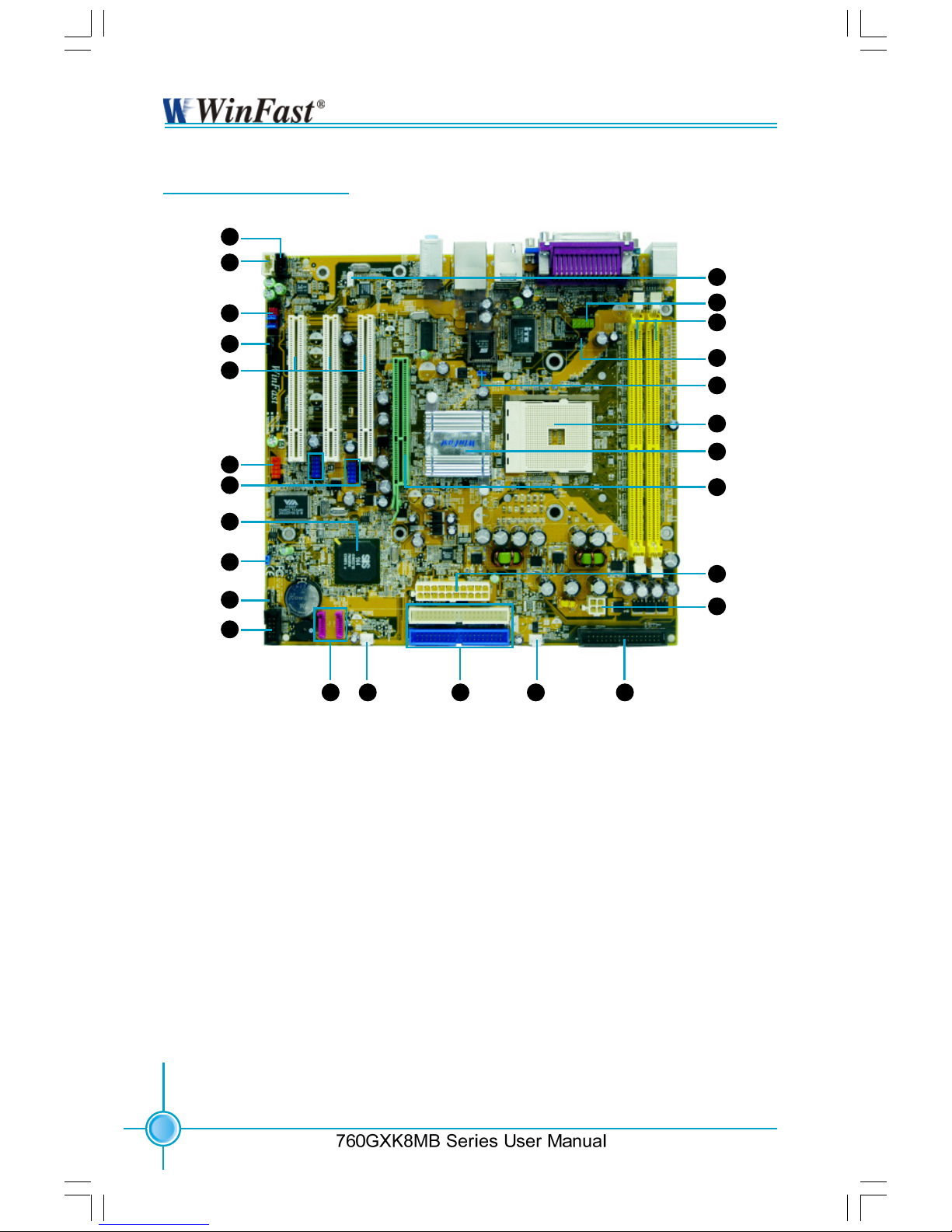
Motherboard Layout
1. CD_IN Connector
2. AUX_IN Connector
3. F_Audio Connector
4. S/PDIF Connector
5. PCI Sots
6. 1394 Connector
(optional)
7. F_USB Connector
8. South Bridge:SiS964
Chipset
9. Clear CMOS Jumper
10. Speaker Connector
11. Front Panel Connector
12. SATA Connector
13. System Fan Connector
14. IDE Connector
15. CPU Fan Connector
16. FDD Connector
17. ATX 12V Power
Connecotr
18. ATX 20-pin Connector
19. AGP Slot
20. North Bridge:SiS760GX
Chipset
21. CPU Socket
22. BIOS-Protection Jumper
23. IrDA Header
24. DDR DIMM Slots
25. COM2 Connector
26. Wake-up On LAN
1
2
3
4
5
6
7
8
9
10
11
12 13 14 15 16
17
18
19
20
21
22
23
24
25
26
760GXK8MB-WINFAST-V1.0 .p65 2004-8-31, 15:254
Page 11
5
Chapter 1 Product Introduction
This chapter introduces the hardware installation process,
including the installation of the CPU and memory. It also
addresses the connection of your power supply, usage of
the rear panel connectors, connection of hard drive and floppy
drive data cables, and setting up various other feature of the
motherboard. Caution should be exercised during the installation process. Please refer to the motherboard layout
prior to any installation and read the contents in this chapter
carefully.
This chapter includes the following information:
CPU
Memory
Power Supply
Rear Panel Connectors
Other Connectors
Expansion Slots
Jumpers
Chapter
760GXK8MB-WINFAST-V1.0 .p65 2004-8-31, 15:255
Page 12
6
Chapter 2 Installation Instructions
Series User Manual
This motherboard supports AMD Athlon64 processors with a 1600 MT/s band-
width and Hyper Thansport
TM
Technology.
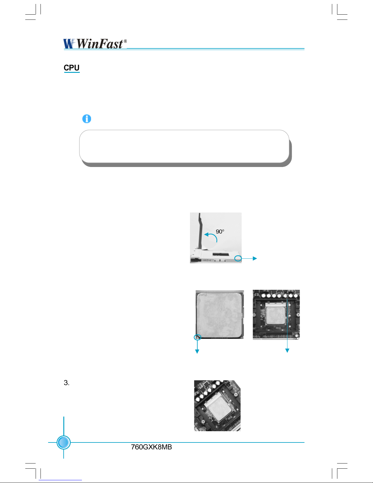
1. Unlock the socket by pressing the lever sideways, then lift it up to a 90
o
angle.
2. Align the cut edge to the gap in the
base of the socket. Carefully insert
the CPU into the socket until it fits in
place.
When the CPU is in place, press it
firmly on the socket while you push
down the socket lever to secure the
CPU. The lever clicks on the side tab
indicates that it is locked.
Gap in the base
Installation of CPU
Follow these steps to install the CPU.
Push down the socket
lever to secure the CPU.
Cut edge
Attention:
The CPU pins must be properly aligned with the holes in the
socket, otherwise the CPU may be damaged.
760GXK8MB-WINFAST-V1.0 .p65 2004-8-31, 15:256
Page 13
7
Chapter 2 Installation Instructions
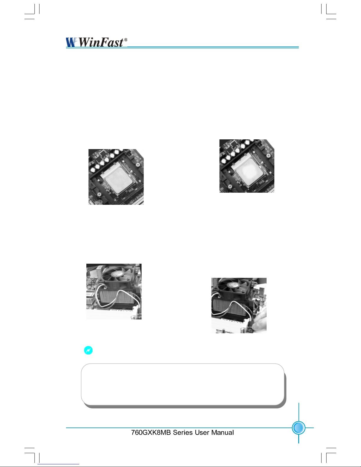
2.If required, apply a light coating of
silica gel to the top of the CPU.
NOTE: The CPU heatsink may have
a pre-applied thermal compound. In
that case, the silica gel is not required.
4.Connect the fan’s power cable
to the appropriate 3-pin terminal
on the motherboard.
1. Locate the CPU retention mecha-
nism base (surrounds the CPU
socket).
3. Attach the fan to the base.
Installation of CPU Fan
New technology allows processors to run at higher and higher frequencies.
To avoid problems arising from high-speed operation, for example,
overheating, you need to install the proper fan. The following procedure is
provided for reference only, please refer to your CPU fan user guide for the
actual procedure.
Warning:
Excessive temperature will severely damage the CPU and
system. Therefore, make sure that the cooling fan works normally at all times in order to prevent overheating and damaging
to the CPU.
760GXK8MB-WINFAST-V1.0 .p65 2004-8-31, 15:267
Page 14
8
Chapter 2 Installation Instructions
Series User Manual
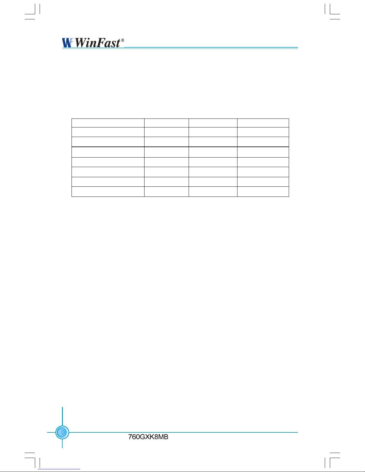
CPU Qualified Vendor List
The following table lists the CPUs that have been tested and qualified for use
with this motherboard.
Package
754 Pin Lidded Oµ PGA
754 Pin Lidded Oµ PGA
754 Pin Lidded Oµ PGA
754 Pin Lidded Oµ PGA
754 Pin Lidded Oµ PGA
754 Pin Lidded Oµ PGA
754 Pin Lidded Oµ PGA
Cache Size
512 KB
512 KB
1 MB
512 KB
1 MB
512 KB
1 MB
Frequency
1800 MHz
2000 MHz
2000 MHz
2200 MHz
2200 MHz
2400 MHz
2400 MHz
Model Number
2800+
3000+
3200+
3200+
3400+
3400+
3700+
760GXK8MB-WINFAST-V1.0 .p65 2004-8-31, 15:268
Page 15
9
Chapter 2 Installation Instructions
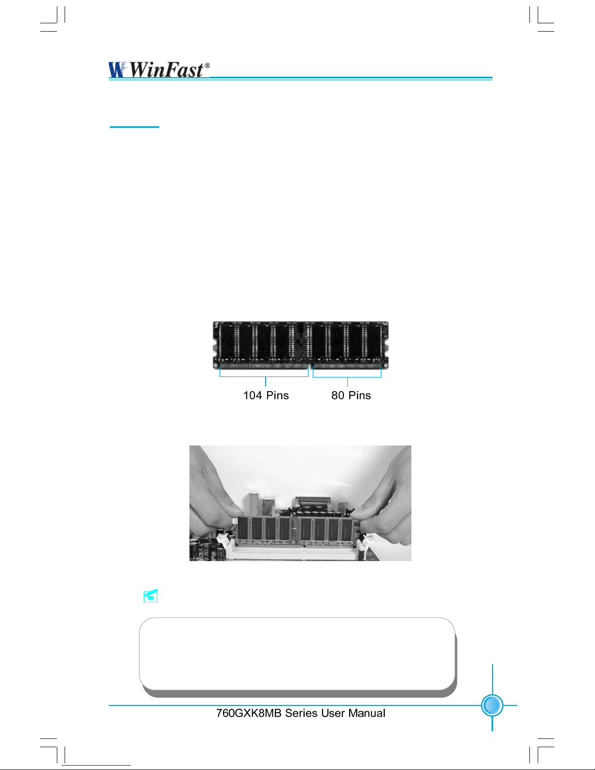
Memory
This motherboard includes two 184-pin slots with 266/333/400 MHz Single
Channel DDR DRAM interface, You must install at least one memory module to
ensure normal operation. If you install two modules, they must be the same
speed. Mixing memory modules from different manufactures are not
recommended.
Installation of DDR Memory
1. There is only one gap in the middle of the DIMM slot, and the memory module
can be fixed in one direction only.
2. Align the memory module to the DIMM slot, and insert the module
vertically into the DIMM slot.
3. The plastic clips at both sides of the DIMM slot will lock automatically.
Note:
Be sure to unplug the AC power supply before adding or re-
moving expansion cards or other system peripherals, espe-
cially the memory devices, otherwise your motherboard or the
system memory might be seriously damaged.
760GXK8MB-WINFAST-V1.0 .p65 2004-8-31, 15:269
Page 16

10
Chapter 2 Installation Instructions
Series User Manual
Vendor Type Size
Infineon PC2100 (DDR266) 256 MB
Samsung PC2100 (DDR266) 256 MB
Kingmax PC2100 (DDR266) 256 MB
Nanya PC2100 (DDR266) 512 MB
Hynix PC2100 (DDR266) 256 MB
Kingston PC2100 (DDR266) 512 MB
RamBo PC2700 (DDR333) 256 MB
Twinmos PC2700 (DDR333) 512 MB
Ramaxel PC2700 (DDR333) 256 MB
Transcend PC2700 (DDR333) 512 MB
Nanya PC2700 (DDR333) 256 MB
Samsung PC2700 (DDR333) 1 GB
Kingmax PC2700 (DDR333) 256 MB
Apacer PC2700 (DDR333) 512 MB
Micron PC2700 (DDR333) 128 MB
A-DATA PC3200 (DDR400) 256 MB
Apacer PC3200 (DDR400) 256 MB
HLX PC3200 (DDR400) 256 MB
V-DATA PC3200 (DDR400) 256 MB
GeiL PC3200 (DDR400) 256 MB
Transcend PC3200 (DDR400) 512 MB
Twinmos PC3200 (DDR400) 512 MB
Kingston PC3200 (DDR400) 512 MB
Memory Qualified Vendor List
The following table lists the memory modules that have been tested and quali-
fied for use with this motherboard.
760GXK8MB-WINFAST-V1.0 .p65 2004-8-31, 15:2610
Page 17

11
Chapter 2 Installation Instructions
Power Supply
This motherboard uses an ATX power supply. In order to avoid damaging any
devices, make sure that they have been installed properly prior to connecting
the power supply.
ATX 12V Power Connector
GND
12V
GND
12V
ATX Power Connector
1
11
-12V
GND
NC
5V
GND
PS-ON
GND
10
20
12V
GND
Pw-OK
3.3V
5V
3.3V
3.3V
GND GND
5V
5V
5V
ATX 12V Power Connector: PWR2
The 4 pin ATX 12 V power supply con-
nects to PWR2 and provides power to
the CPU.
ATX Power Connector: PWR1
PWR1 is the ATX power supply
connector. Make sure that the power
supply cable and pins are properly
aligned with the connector on the
motherboard. Firmly plug the power sup-
ply cable into the connector and make
sure it is secure.
Rear Panel Connectors
This motherboard provides the following ports as below:
Serial Port
(COM1)
USB 2.0 Ports
PS/2 Mouse Port
Line-in
Line-out
MIC
1
2
3
6
PS/2 Keyboard Port
9
VGA Connector
4
Parallel Port
(Printer Port)
LAN Port
7
1394 Port
(optional)
5
8
GND
760GXK8MB-WINFAST-V1.0 .p65 2004-8-31, 15:2611
Page 18

12
Chapter 2 Installation Instructions
Series User Manual
PS/2 Mouse Port
This green 6-pin connector is for a PS/2 mouse.
PS/2 Keyboard Port
This purple 6-pin connector is for a PS/2 keyboard.
Serial Port: COM1
This 9-pin COM1 port is for pointing devices or other serial devices.
VGA Connector
The VGA connector is for output to VGA-compatible device.
Parallel Port: Printer Port
The 25-pin port connects a parallel printer, a scanner, or other devices.
USB Ports
These four Universal Serial Bus (USB) ports are available for connecting USB 2.
0/1.1 devices.
1394 Port (optional)
This digital interface supports electronic devices such as digital cameras,
scanners, and printers.
LAN Port
This port allows connection to a Local Area Network (LAN) through a network
hub.
Line-in jack, Line-out jack, Microphone jack
When using a two-channel sound source, the Line-out jack is used to connect
to speaker or headphone; the Line-in port connects to an external CD player,
tape player or other audio device. The Microphone jack is used to connect to the
microphone.
1
2
3
5
4
6
7
8
9
760GXK8MB-WINFAST-V1.0 .p65 2004-8-31, 15:2612
Page 19

13
Chapter 2 Installation Instructions
Other Connectors
This motherboard includes interfaces for Floppy, IDE HDD, SATA, USB, 1394, IR
module, CPU fan, system fan, and others.
FDD Connector: FLOPPY
This motherboard includes a standard FLOPPY interface, supporting 360 K, 720 K,
1.2 M, 1.44 M, and 2.88 M FDDs.
HDD Connectors: PIDE & SIDE
These connectors support the provided Ultra DMA133/100/66 IDE hard disk
ribbon cable. Connect the cable’s blue connector to the primary (recommended)
or secondary IDE connector, then connect the gray connector to the Ultra DMA133/
100/66 slave device (hard disk drive) and the black connector to the Ultra DMA133/
100/66 master device. If you install two hard disks, you must configure the
second drive as a slave device by setting its jumper accordingly. Refer to the
hard disk documentation for the jumper settings.
Attention:
Ribbon cables are directional, therefore, be sure to always connect
with the cable on the same side as pin 1 of the PIDE/SIDE or
FLOPPY connector on the motherboard.
760GXK8MB-WINFAST-V1.0 .p65 2004-8-31, 15:2613
Page 20

14
Chapter 2 Installation Instructions
Series User Manual
Front Panel Connector: FP1
This motherboard includes one connector
for connecting the front panel switch and
LED indicator.
Hard Disk LED Connector (HD-LED)
The connector connects to the case’s IDE indicator LED indicating the activity
status of hard disks.
Reset Switch (RESET-SW)
Attach the connector to the Reset switch on the front panel of the case; the
system will restart when the switch is pressed.
Power LED Connector (PWR-LED)
Attach the connector to the power LED on the front panel of the case. The Power
LED indicates the system’s status. When the system is in S0 status, the LED is
on. When the system is in S1 status, the LED is blink. When the system is in S3,
S4, S5 status, the LED is off.
Power Switch Connector (PWR-SW)
Attach the connector to the power button on the front panel of the case. Pushing
this switch allows the system to be turned on and off rather than using the
power supply button.
NC
HD-LED
RESET-SW
PWR-LED
PWR-SW
+ -
+ -
9 10
1 2
FP1!
IrDA Header: IR
The IrDA infrared transmission allows your
computer to send and receive data via an
infrared ray. The relevant parameters for the
BIOS Integrated Peripherals
should be set prior to using this function.
+5V
GND
IRRXIRTX
Empty
1
IR
760GXK8MB-WINFAST-V1.0 .p65 2004-8-31, 15:2614
Page 21

15
Chapter 2 Installation Instructions
USB Header: F_USB 1, F_USB 2
Besides four USB ports on the rear panel,
the series of motherboard also have two 10-
pin headers on board which may connect to
front panel USB cable(optional) to provide
additional four USB ports.
F_USB 1
F_USB 2
D4-
VCC
D5+
D5-
Empty
GND
NC
VCC
GND
D4+
1 2
9 10
1 2
9 10
D6-
VCC
D7+
D7-
Empty
GND
NC
VCC
GND
D6+
Fan Connectors: CPU_FAN, FAN1
There are two fan headers on this
motherboard. These fans will be automatically turned off after the system enters suspend mode.
CPU_FAN
+12V SENSEGND
1
+12V
SENSEGND
1
FAN1
Audio Connectors: CD_IN, AUX_IN
CD_IN, AUX_IN is Sony standard CD audio
connector. It can be connected to a CD-ROM
drive through a CD audio cable.
CD_IN
GND
CD_L
CD_R
AUX_IN
AUX_L
GND
AUX_R
760GXK8MB-WINFAST-V1.0 .p65 2004-8-31, 15:2615
Page 22

16
Chapter 2 Installation Instructions
Series User Manual
1394 Header: F_1394 (optional)
The 1394 expansion cable can be connected to either the front (provided that the
front panel of your chassis is equipped with
the appropriate interface) or rear panel of
the chassis.
Wake-up On LAN: WOL
Through the Wake-Up On LAN function, a
wake event occurring from the network can
wake up the system. To utilize this function,
please be sure to use an ATX 12 V power
supply with a 5VSB line capable of delivering a current of at least 1 A, and a LAN
adapter which supports this function. Then
connect the header to the relevant connector on the LAN adapter, set “MACPME Power
Up Control” to “Enabled” in the “Power Management Setup” section of the CMOS
SETUP. Save and exit, then boot the operating system once to make sure this function takes effect.
WOL
Signal for waking up
+5VSB
GND
1
F_1394
1
Empty
2
S-ATA Connectors: SATA-1, SATA-2
The S-ATA header is used to connect the S-
ATA device to the motherboard.
These connectors support the thin Serial
ATA cables for primary internal storage
devices. The current S-ATA interface allows
up to 150 MB/s data transfer rate.
SATA-1/SATA-2
GND
GND
GND
TX+
TX-
RX+
RX-
760GXK8MB-WINFAST-V1.0 .p65 2004-8-31, 15:2616
Page 23

17
Chapter 2 Installation Instructions
1SPDIF Out Connector: SPDIF_OUT
The SPDIF out connector is capable of providing digital audio to external speakers or
compressed AC3 data to an external Dolby
digital decoder.
5V
GND
Empty
DATA
Audio Interface: F_AUDIO
The audio interface provides two kinds of
audio output choices: the Front Audio, the
Rear Audio. Their priority is sequenced from
high to low (Front Audio to Rear Audio). If head-
phones are plugged into the front panel of
the chassis (using the Front Audio), then the
Line-out (Rear Audio) on the rear panel will
not work. If you do not want to use the Front
Audio, pin 5 and 6, pin 9 and 10 must be
shorted, and then the signal will be sent to
the rear audio port.
F_AUDIO
MIC_GND
MIC
+5VAC
MIC_PWR
AUT_RET_R
AUD_OUT_R
EMPTY
AUD_OUT_L
AUT_RET_L
1
2
910
NC
Speaker Connector: SPK
The speaker connector is used to connect
speaker of the chassis.
1
SPEAKER
SPK
SPKJ
Emypty
NC
COM2: Additional COM Header
This board provides an additional serial COM
header for your computer. You need connect
the switching-cable to this header first, and
then connect the serial COM device with the
port of the switching-cable.
1
2
9
10
COM2
DSR#
RI#
GND
RTS#
TXD
EMPTY
CTS#
RXD
760GXK8MB-WINFAST-V1.0 .p65 2004-8-31, 15:2617
Page 24

18
Chapter 2 Installation Instructions
Series User Manual
Expansion Slots
This motherboard includes three 32-bit Master PCI bus slots and one AGP
slot.
PCI Slots
The expansion cards can be installed in the three PCI slots. When you install or
take out such cards, you must make sure that the power plug has been pulled
out. Please carefully read the instructions provided for such cards, and install
and set the necessary hardware and software for such cards, such as the
jumper or BIOS settings.
AGP Slot
This motherboard has an AGP slot that supports 1.5 V AGP cards. AGP is an
interfacing specification designed to display 3D images. It provides a specialized
66 MHz, 32-bit channel to allow the graphic controller to directly access the
master memory and supports 4X and 8X speeds.
Installing an expansion card
1. Before installing the expansion card, read the documentation that came
with it and make the necessary hardware settings for the card.
2. Be sure to unplug the power cord before adding or removing expansion cards.
3. Remove the bracket opposite the slot that you intend to use.
4. Align the card connector with the slot and press firmly until the card is
completely seated on the slot.
5. Secure the card to the chassis with the screw you removed earlier.
760GXK8MB-WINFAST-V1.0 .p65 2004-8-31, 15:2618
Page 25

19
Chapter 2 Installation Instructions
GeForce2 GeForce2 MX 400 32 MB
LeadTek LeadTek S650 128 MB
GA-GF GA-GF 1280 GeForce 2 MX 32 MB
ELSA ELSA 511 64 MB
UNIKA UNIKA 7917 GF 4 MX 440 64 MB
ATI ATI 9700 8X 128 MB
MSI MSI-5800 128 MB
MSI MSI-5600 (8912) 128 MB
MSI MSI-5200 (8923) 128 MB
MSI MSI-Mx440 (8X,8891) 64 MB
MSI MSI-5200 (8911) 128MB
AGP Qualified Vendor List
The following table lists the AGP cards that have been tested and qualified for
use with this motherboard.
760GXK8MB-WINFAST-V1.0 .p65 2004-8-31, 15:2619
Page 26

20
Chapter 2 Installation Instructions
Series User Manual
Jumpers
Users can change the jumper settings on this motherboard if needed. This
section explains how to use the various functions of this motherboard by changing the jumper settings. Users should read the following contents carefully prior
to modifying any jumper settings.
Description of Jumpers
For the jumpers on this motherboard, pin 1 can be identified by the silkscreen printed
next to it. However, in this manual, pin 1 is simply
labeled as “1”.
The following table provides some explanation of the jumper pin settings.
Users should refer to this when adjusting jumper settings.
Jumper Diagram Definition Description
Set pin 1 and pin 2 closed
Set pin 2 and pin 3 closed
Closed Set the pin closed
Open Set the pin opened
760GXK8MB-WINFAST-V1.0 .p65 2004-8-31, 15:2620
Page 27

21
Chapter 2 Installation Instructions
Clear CMOS Jumper: CLS_CMOS
This motherboard uses the CMOS RAM to store
all the set parameters. The CMOS can be
cleared by removing the CMOS jumper.
How to clear CMOS?
1. Turn off the AC power supply and connect pins
1 and 2 together using the
jumper cap.
2. Return the jumper setting to normal (locked
pins 2 and 3 together with the
jumper cap).
3. Turn the AC power supply back on.
Clear CMOS Jumper
Normal status
(default)
Clear CMOS
BIOS-Protection Jumper: FWH_EN
The motherboard BIOS is inside the FWH. If
the jumper FWH_EN is set as disabled (Pin2
& Pin3), the system BIOS is protected from
being attacked by a serious virus, such as the
CIH virus. You will be unable to flash the BIOS
to the motherboard when the system BIOS is
protected.
Flash Write
Disable
Flash Write
Enable
(Default)
BIOS-Protection Jumper
1 2 3
1 2 3
1. Disconnect the power cable before adjusting the jumper settings.
2. Do not clear the CMOS while the system is turned on.
Warning:
760GXK8MB-WINFAST-V1.0 .p65 2004-8-31, 15:2621
Page 28

T-- This page is intentionally left blank --his
This chapter tells how to change system settings through the
BIOS Setup menus. Detailed descriptions of the BIOS param-
eters are also provided.
You have to run the Setup Program when the following cases
occur:
1. An error message appears on the screen during the
system POST process.
2. You want to change the default CMOS settings.
This chapter includes the following information:
Enter BIOS Setup
Main Menu
Standard CMOS Features
BIOS Features
Advanced BIOS Features
Advanced Chipset Features
Integrated Peripherals
Power Management Setup
PnP/PCI Configurations
PC Health Status
Frequency/Voltage Control
Load Fail-Safe Defaults
Load Optimized Defaults
Set Supervisor/User Password
Save & Exit Setup
Exit Without Saving
Chapter
760GXK8MB-WINFAST-V1.0 .p65 2004-8-31, 15:2622
Page 29

23
Chapter 3 BIOS Description
Enter BIOS Setup
The BIOS is the communication bridge between hardware and software,
correctly setting up the BIOS parameters is critical to maintain optimal system
performance. Power on the computer, when the following message briefly
appears at the bottom of the screen during the POST (Power On Self Test),
press <Del> key to enter the Award BIOS CMOS Setup Utility.
Press TAB to show POST screen, DEL to enter SETUP.
Main Menu
The main menu allows you to select from the list of setup functions and two exit
choices. Use the arrow keys to select among the items and press <Enter> to
accept or go to the sub-menu.
The items in the BIOS Setup main menu are explained below:
Standard CMOS Features
The basic system configuration can be set up through this menu.
BIOS Features
The general system features can be set up through this menu.
Note:
We do not suggest that you change the default parameters in the
BIOS Setup, and we shall not be responsible for any damage that
results from any changes that you make.
760GXK8MB-WINFAST-V1.0 .p65 2004-8-31, 15:2623
Page 30

24
Chapter 3 BIOS Description
Advanced BIOS Features
The advanced system features can be set up through this menu.
Advanced Chipset Features
The values for the chipset can be changed through this menu, and the sys-
tem performance can be optimized.
Integrated Peripherals
Onboard peripherals can be set up through this menu.
Power Management Setup
All the items of Green function features can be set up through this menu.
PnP/PCI Configurations
The system’s PnP/PCI settings and parameters can be modified through
this menu.
PC Health Status
This will display the current status of your PC.
Frequency/Voltage Control
Frequency and voltage settings can be adjusted through this menu.
Load Fail-Safe Defaults
The fail-safe default BIOS settings can be loaded through this menu.
Load Optimized Defaults
The optimal performance settings can be loaded through this menu,
however, the stable default values may be affected.
Set Supervisor/User Password
The supervisor/user password can be set up through this menu.
Save & Exit Setup
Save CMOS value settings to CMOS and exit setup.
Exit Without Saving
Abandon all CMOS value changes and exit setup.
760GXK8MB-WINFAST-V1.0 .p65 2004-8-31, 15:2624
Page 31

25
Chapter 3 BIOS Description
Standard CMOS Features
This sub-menu is used to set up the standard CMOS features, such as the
date, time, HDD model and so on. Use the arrow keys select the item to set
up, and then use the <PgUp> or <PgDn> keys to choose the setting values.
Date
This option allows you to set the desired date (usually as the current date)
with the <day><month><date><year> format.
day weekday from Sun. to Sat., defined by BIOS (read-only).
month month from Jan. to Dec.
date date from 1
st
to 31st, can be changed by using the keyboard.
year year, set up by users.
Time
This option allows you to set up the desired time (usually as the current time)
with <hour><minute><second> format.
IDE Channel 0/1 Master/Slave & IDE Channel 2/3 Master
These categories identify the HDD types of 4 IDE channels installed in the
computer system. There are three choices provided for the Enhanced IDE BIOS:
None, Auto, and Manual. “None” means no HDD is installed or set; “Auto” means
the system can auto-detect the hard disk when booting up; by choosing “Manual”
and changing Access Mode to “CHS”, the related information should be entered
manually. Enter the information directly from the keyboard and press < Enter>:
Standard CMOS Features Menu
Cylinder Number of cylinders Head Number of heads
Precomp Write pre-compensation Landing Zone Landing Zone
Sector Number of sectors
760GXK8MB-WINFAST-V1.0 .p65 2004-8-31, 15:2625
Page 32

26
Chapter 3 BIOS Description
Award (Phoenix) BIOS can support 4 HDD modes: CHS, LBA and Large or
Auto mode.
CHS For HDD<528 MB
LBA For HDD>528 MB & supporting LBA (Logical Block Addressing)
Large For HDD>528 MB but not supporting LBA
Auto Recommended mode
Drive A/B
This option allows you to select the kind of FDD to be installed, including
“None”, [360 K, 5.25 in], [1.2 M, 5.25 in], [720 K, 3.5 in], [1.44 M, 3.5 in] and [2.
88 M, 3.5 in].
Video
The following table is provided for your reference in setting the display mode for
your system.
EGA/ VGA Enhanced Graphics Adapter / Video Graphic Array. For EGA,
VGA, SEGA, SVGA, or PGA monitor adapters.
CGA 40 Color Graphic Adapter, powering up in 40 column mode.
CGA 80 Color Graphic Adapter, powering up in 80 column mode.
MONO Monochrome adapter, including high resolution monochrome
adapters.
760GXK8MB-WINFAST-V1.0 .p65 2004-8-31, 15:2626
Page 33

27
Chapter 3 BIOS Description
Memory
This is a display-only category, determined by POST (Power On Self Test)
of the BIOS.
Base Memory The BIOS POST will determine the amount of base
(or conventional) memory installed in the system.
Extended Memory The BIOS determines how much extended
memory is present during the POST.
Total Memory Total memory of the system.
Halt On
This category determines whether or not the computer will stop if an error is
detected during powering up.
All Errors Whenever the BIOS detects a nonfatal error, the
system will stop and you will be prompted.
No Errors The system boot will not stop for any errors that may
be detected.
All, But Keyboard The system boot will not stop for a keyboard error;
but it will stop for all other errors.
All, But Diskette The system boot will not stop for a diskette error; but
it will stop for all other errors.
All, But Disk/Key The system boot will not stop for a keyboard or a
disk error, but it will stop for all other errors.
760GXK8MB-WINFAST-V1.0 .p65 2004-8-31, 15:2627
Page 34

28
Chapter 3 BIOS Description
BIOS Features
[SuperBoot] SuperBoot (Default: Disabled)
SuperBoot allows system-relevant information to be stored in CMOS upon
the first normal startup of your PC, and the relevant parameters will be
restored to help the system start up more quickly on each subsequent startup.
[SuperBIOS-Protect] SuperBIOS-Protect (Default: Disabled)
Super-BIOS Protect function protects your PC from being affected by viruses,
e.g. CIH.
[SuperRecovery] SuperRecovery Hotkey (Default: LSHIFT+F12)
SuperRecovery provides the users with an excellent data protection and
HDD recovery function.
[SuperSpeed] CPU Clock (depend on CPU)
The conventional over-clock method uses the jumpers on the motherboard,
and it is both troublesome and apt to errors. By using SuperSpeed, a CPU
can be overclocked by keying in the desired in the CPU clock range.
BIOS Features Menu
Warning:
Be sure your selection is right. CPU overclock will be dangerous!
We will not be responsible for any damage caused.
760GXK8MB-WINFAST-V1.0 .p65 2004-8-31, 15:2628
Page 35

29
Chapter 3 BIOS Description
Advanced BIOS Features
Hard Disk Boot Priority
This option is used to select the priority for HDD startup. After pressing
<Enter>, you can select the HDD using the <PageUp>/<PageDn> or Up/
Down arrow keys, and change the HDD priority using <+> or <->; you can
exit this menu by pressing <Esc>.
Virus Warning (Default: Disabled)
This option is used to set up the virus warning message for the IDE HDD
boot sector. When set to Enabled, a warning message will appear on the
screen if any program wants to write any information to this sector, and will
give an audible warning.
Note: Such function provides protection to the startup sector only; it does
not protect the entire hard disk.
Quick Power On Self Test (Default: Enabled)
With this function enabled, the system will skip the normal test while
starting up, therefore reducing the overall start up time.
First/Second/Third Boot Device (Default: Floppy/Hard Disk/LS120)
This option allows you to set the boot device sequence.
Boot Other Device (Default: Enabled)
With this function set to Enabled, the system will boot from some other
devices if the first/second/third starting devices failed.
Security Option (Default: Setup)
When it is set to Setup, a password is required to enter the CMOS Setup
screen; when it is set to System, a password is required not only to enter
CMOS Setup, but also to startup your PC, as well.
Advanced BIOS Features Menu
760GXK8MB-WINFAST-V1.0 .p65 2004-8-31, 15:2629
Page 36

30
Chapter 3 BIOS Description
Advanced Chipset Features
DRAM Configuration
Press <Enter> to set the items about DRAM Configuration.
AGP & P2P Bridge Control
Press <Enter> to set the items about AGP & P2P Bridge.
OnChip VGA Control
Press <Enter> to set the items about OnChip VGA Control.
Memory Hole at 15M-16M (Default: Disabled)
This option is used to determine whether the 15 M-16 M address field of
memory is reserved for the ISA expansion card.
System BIOS Cacheable (Default: Disabled)
Select “Enabled” to allow catching of the system BIOS which may improve
performance. If any other program writes to this memory area, a system
error may result.
Advanced Chipset Features Menu
760GXK8MB-WINFAST-V1.0 .p65 2004-8-31, 15:2630
Page 37

31
Chapter 3 BIOS Description
Integrated Peripherals
Integrated Peripherals Menu
SIS OnChip IDE Device
Press <Enter> to set onchip IDE device. Please refer to page 32.
SIS OnChip PCI Device
Press <Enter> to set onchip PCI device. Please refer to page 33.
Onboard SuperIO Device
Press <Enter> to set onchip onboard SuperIO device. Please refer to page
34.
Onboard Lan Boot ROM (Default: Disabled)
This option is used to decide whether to invoke the boot ROM of the onboard
LAN chip.
Init Display First (Default:PCI Slot)
This option is used to set which display device will be used first when your
PC starts up.
760GXK8MB-WINFAST-V1.0 .p65 2004-8-31, 15:2631
Page 38

32
Chapter 3 BIOS Description
Internal PCI/IDE (Default: Both)
This option is used to set the ports of onboard IDE.
IDE Primary/Secondary Master/Slave PIO (Default: Auto)
These four items let you assign which kind of PIO (Programmer Input/Output)
is used by IDE devices. Choose “Auto” to let the system auto detect which PIO
mode is the best or select a PIO mode from 0-4
Primary/Secondary Master/Slave UItra DMA (Default: Auto)
UItra DMA technology provides faster access to IDE devices. If you install a
device that supports UItra DMA, change the appropriate items on this list to
Auto.
IDE DMA transfer access (Default: Enabled)
This option is used to enable or disable IDE DMA transfer access.
IDE Burst Mode (Default: Enabled)
This option is used to enable or disable IDE burst mode.
SIS Onchip IDE Device Menu
760GXK8MB-WINFAST-V1.0 .p65 2004-8-31, 15:2632
Page 39

33
Chapter 3 BIOS Description
SIS USB Controller (Default: Enabled)
This option is used to enable or disable SIS USB controller.
USB 2.0 Supports (Default: Enabled)
This option is used to enable or disable USB 2.0.
USB Keyboard Support (Default: Enabled)
This option is used to set USB keyboard support.
USB Mouse Support (Default: Enabled)
This option is used to set USB mouse support.
SIS AC97 AUDIO (Default: Enabled)
This option is used to enable or disable SIS AC97 audio.
SIS 10/100M ETHERNET (Default: Enabled)
This option is used to enable or disable SiS 10/100 M ethernet.
SIS OnChip PCI Device Menu
760GXK8MB-WINFAST-V1.0 .p65 2004-8-31, 15:2633
Page 40

34
Chapter 3 BIOS Description
Onboard FDC Controller (Default: Enabled)
This option is used to set whether the onboard FDC controller is enabled.
Onboard Serial Port 1/2 (Default: 3F8/IRQ4 / 2F8/IRQ3)
These options are used to assign the I/O address and interrupt request
(IRQ) for the onboard serial port 1/2.
Note: Do not try to set the same values for serial port 1 and 2.
UART Mode Select (Default: Normal)
Use this option to select the UART mode. The setting value is determined by
the infrared module installed on the board.
UR2 Duplex Mode (Default: Half)
This option is available when UART 2 mode is set to either ASKIR or IRDA. This
option enables you to determine the infrared function of the onboard infrared
chip.
Onboard Parallel Port (Default: 378/IRQ7)
This option allows you to determine onboard parallel port controller I/O ad-
dress and interrupt request (IRQ).
Parallel Port Mode (Default: SPP)
Select an address and corresponding interrupt request for the onboard parallel
port.
ECP Mode Use DMA (Default: 3)
Select a DMA channel for the parallel port when using the ECP mode. This field
is only configurable if Parallel Port Mode is set to ECP.
Onboard SuperIO Device Menu
760GXK8MB-WINFAST-V1.0 .p65 2004-8-31, 15:2634
Page 41

35
Chapter 3 BIOS Description
Power Management Setup
ACPI function (Default: Enabled)
ACPI stands for “Advanced Configuration and Power Interface”. ACPI is a
standard that defines power and configuration management interfaces between
an operating system and the BIOS. In other words, it is a standard that
describes how computer components work together to manage system
hardware. In order to use this function, the ACPI specification must be supported
by the OS (for example, Windows2000 or WindowsXP).
ACPI Suspend Type (Default: S3(STR))
This option is used to set the energy saving mode of the ACPI function.
When you select “S1 (POS)” mode, the power will not shut off and the
supply status will remain as it is, in S1 mode the computer can be resumed
at any time. When you select “S3 (STR)” mode, the power will be cut off after
a delay period. The status of the computer before it enters STR will be saved
in memory, and the computer can quickly return to previous status when the
STR function wakes. When you select “S1 & S3” mode, the system will
automatically select the delay time.
Power Management (Default: User Define)
This option is used to set the power management scheme.
Suspend Mode (Default: Disabled)
This option is used to set the idle time before the system enters into sleep
status.
Video Off Option (Default: Susp, Stby - > Off)
This option is used to set video off option.
Power Management Setup Menu
760GXK8MB-WINFAST-V1.0 .p65 2004-8-31, 15:2635
Page 42

36
Chapter 3 BIOS Description
MODEM Use IRQ (Default: NA)
This option is used to set the IRQ in which the modem can use. The system
will automatically wake up when the modem receives an incoming call.
PM Wake Up Events
Press <Enter> to set the items of PM Wake Up Events.
AMD K8 Cool ’n’ Quiet Control (Default:Auto)
When this item is set as “Auto”, AMD Cool ’n’ Quiet. technology controls your
system’s level of processor performance automatically, dynamically adjust-
ing the operating frequency and voltage according to the task at hand.
760GXK8MB-WINFAST-V1.0 .p65 2004-8-31, 15:2636
Page 43

37
Chapter 3 BIOS Description
PnP/PCI Configurations
Reset Configuration Data (Default: Disabled)
This option is used to set whether the system is permitted to automatically
distribute IRQ DMA and I/O addresses when each time the machine is turned
on.
Resources Controlled By (Default: Auto (ESCD))
This option is used to define the system resource control scheme. If all cards
you use support PnP, then select Auto (ESCD) and the BIOS will automatically
distribute interruption resources. If the ISA cards you installed not supporting
PnP, you will need to select “Manual” and manually adjust interruption resources in the event of hardware conflicts. However, since this motherboard
has no ISA slot, this option does not apply.
IRQ Resources
Press the <Enter> key, then manually set IRQ resources.
PCI/VGA Palette Snoop (Default: Disabled)
If you use a nonstandard VGA card, use this option to solve graphic acceleration card or MPEG audio card problems (e.g., colors not accurately displayed).
Raid Card Boot First (Default: Disabled)
This option is used to set Raid card boot first.
PnP/PCI Configurations Menu
760GXK8MB-WINFAST-V1.0 .p65 2004-8-31, 15:2637
Page 44

38
Chapter 3 BIOS Description
PC Health Status
Shutdown Temperature (Default: Disabled)
This option is used to set the system temperature upper limit. When the
temperature exceeds the setting value, the motherboard will automatically cut
off power to the computer.
760GXK8MB-WINFAST-V1.0 .p65 2004-8-31, 15:2638
Page 45

39
Chapter 3 BIOS Description
Frequency/Voltage Control
Auto Detect PCI Clk (Default: Enabled)
This option is used to set whether the clock of an unused PCI slot will be
disabled to reduce electromagnetic interference.
Async SRC/ZCLK/AGP/PCI (Default: Disabled)
Enabling this item can fix the SRC/ZCLK/AGP/PCI in a safe value to ensure
the PCI/SATA device stability when CPU overclocks.
Spread Spectrum (Default: Disabled)
If you enable spread spectrum, it can significantly reduce the EMI (ElectroMagne
-tic Interference) generated by the system.
Frequency/Voltage Control Menu
760GXK8MB-WINFAST-V1.0 .p65 2004-8-31, 15:2639
Page 46

40
Chapter 3 BIOS Description
Load Optimized Defaults
Load Fail-Safe Defaults
Select this option and press <Enter>, it will pop up a dialogue box to allow you
to load default set by BIOS. Press <Y> and then <Enter> to load default. Press
<N> and <Enter>, it will not load. The defaults set by BIOS have set the basic
functions of system to ensure the stability of system. But if your computer fails to
properly run, you may load the default to make the system recover normal, then
carry out failure testing in next step. If you only want to load the default as an
option, you can select this option and press the key <F6>.
Select this option and press <Enter>, it will pop up a dialogue box to let you load
the optimized defaults set by BIOS. Press <Y> and <Enter> to load the optimized
defaults. Press <N> and <Enter>, it will not load. The defaults set by BIOS have
set the optimized performance parameters of system to improve the performances of system components. But if the optimized performance parameters
to be set cannot be supported by your hardware devices, it will cause system to
make mistakes or not stable. If you only want to load the optimized defaults as
an option, you can select this option and press the key <F7>.
Set Supervisor/User Password
The preferential grade of supervisor password is higher than user password.
You can use supervisor password to start into system or enter into CMOS setting program to amend the settings. You can also use user password to start
into system, or enter into CMOS setting menu to check, but if you have set
supervisor password, you cannot amend the settings.
When you select Set Supervisor / User Password, it will appear the following
message in the center of screen, which will help you to set password.
Enter Password:
Enter your password, not exceeding 8 characters, then press <Enter>, the password you have entered now will replace the previous password. When the system requires you to determine this password, you can enter this password and
press <Enter>.
If you do not need this setting, you can press <Enter> when the screen prompts
you to enter password, and the screen will appear the following message to
show this function invalid. In this case, you can freely enter into system and
CMOS setting program.
PASSWORD DISABLED!!!
Press any key to continue...
760GXK8MB-WINFAST-V1.0 .p65 2004-8-31, 15:2640
Page 47

41
Chapter 3 BIOS Description
Save & Exit Setup
Select this option and press <Enter>, it will show the following message in the
center of screen:
SAVE to CMOS and EXIT (Y/N) ? Y
At this time, press <Y> to save your amendment in CMOS and exit from this
program; press <N>/<ESC> to return main menu.
Exit Without Saving
Select this option and press <Enter>, it will show the following message in the
center of screen:
Quit Without Saving (Y/N) ? N
At this time, press <Y> to exit CMOS but it does not save your amendment in
CMOS; press <N>/<ESC> to return main menu.
Under the menu “Advanced BIOS Features Setup”, if you select “System” in
Security Option, the screen will prompt you to enter password once the system
is started or you want to enter CMOS setting program. If the password is wrong,
it will refuse you to continue.
Under the menu “Advanced BIOS Features Setup”, if you select “Setup” in Security Option, the screen will prompt you to enter password only when you enter
CMOS setting program.
760GXK8MB-WINFAST-V1.0 .p65 2004-8-31, 15:2641
Page 48

Chapter
The utility CD that comes with the motherboard contains useful
software and several utility drivers that enhance the mother-
board features.
This chapter includes the following information:
Utility CD content
Start to install drivers
760GXK8MB-WINFAST-V1.0 .p65 2004-8-31, 15:2642
Page 49

43
Chapter 4 Driver CD Introduction
Utility CD Content
This motherboard comes with one Utility CD. To begin using the CD, simply insert
the CD into your CD-ROM drive. The CD will automatically displays the main
menu screen.
1. Install Drivers
Using this choice, you can install all the drivers for your motherboard. You should
install the drivers in order, and you need to restart your computer after the drivers all installed.
A. IDE Driver B. SiS SATA RAID (optional)
C. AGP Driver D. VGA Driver
E. DirectX 9.0b F. USB 2.0 Driver
G. Audio Driver H. LAN Driver
2. Accessories
Use this option to install additional software programs.
A. SuperUtility
a. SuperLogo
SuperLogo can display user-designed graphics and pictures, such as
company logo or personal photos, thus making your PC more
personalized and friendly.
b. SuperStep
SuperStep is a powerful and easy-to-use tool for overclocking. You can
quickly increase your CPU’s frequency through its user-friendly interface.
It will enhance your CPU’s performance and meet all kinds of DIY
requirements.
c. SuperUpdate
SuperUpdate function can help update the BIOS through internet directly.
If you want to know the detail information, please visit our website:
http://www.foxconnchannel.com/
B. Adobe Reader
C. Norton Internet Security 2004
3. Browse CD
Click here to browse CD content.
4. Homepage
Click here to visit FOXCONN motherboard homepage.
760GXK8MB-WINFAST-V1.0 .p65 2004-8-31, 15:2643
Page 50

44
Chapter 4 Driver CD Introduction
Start to install drivers
Select <Install Driver>, and click it to enter the install drivers screen. You can
select the driver that you want to install and begin the setup steps.
Follow screen
order to install
motherboard
drivers
760GXK8MB-WINFAST-V1.0 .p65 2004-8-31, 15:2644
 Loading...