

Page 1

Model
Owner’s Manual
Multitracker
Page 2

Model X-34 Owner’s Manual
CAUTION
RISK OF ELECTRIC SHOCK
DO NOT OPEN
CAUTION: TO REDUCE THE RISK OF ELECTRIC SHOCK,
DO NOT REMOVE COVER (OR BACK).
NO USER - SERVICEABLE PARTS INSIDE.
REFER SERVICING TO QUALIFIED SERVICE PERSONNEL.
"WARNING"
"TO REDUCE THE RISK OF FIRE OR ELECTRIC
SHOCK, DO NOT EXPOSE THIS APPLIANCE TO RAIN
OR MOISTURE."
SAFETY INSTRUCTIONS
1. Read Instructions - All the safety and operating instructions
should be read before the appliance is operated.
2. Retain Instructions - The safety and operating instructions should
be retained for future reference.
3. Heed Warnings - All warnings on the appliance and in the
operating instructions should be adhered to.
4. Follow Instructions - All operating and use instructions should
be followed.
5. Water and Moisture - The appliance should not be used near
water - for example, near a bathtub, washbowl, kitchen sink,
laundry tub, in a wet basement, or near a swimming pool, and
the like.
6. Carts and Stands - The appliance should be used only with a
cart or stand that is recommended by the manufacturer.
An appliance and cart combination should be moved with care.
Quick stops, excessive force, and uneven surfaces may cause
the appliance and cart combination to overturn.
7. Wall or Ceiling Mounting - The appliance should be mounted to
a wall or ceiling only as recommended by the manufacturer.
8. Ventilation - The appliance should be situated so that its location
or position dose not interfere with its proper ventilation. For
example, the appliance should not be situated on a bed, sofa,
rug, or similar surface that may block the ventilation openings;
or, placed in a built-in installation, such as a bookcase or cabinet
that may impede the flow of air through the ventilation openings.
CAUTION:
TO PREVENT ELECTRIC SHOCK, MATCH WIDE BLADE
OF PLUG TO WIDE SLOT, FULLY INSERT.
ATTENTION:
POUR EVITER LES CHOCS ELECTRIQUES,
INTRODUIRE LA LAME LA PLUS LARGE DE LA FICHE
DANS LA BORNE CORRESPONDANTE DE LA PRISE
ET POUSSER JUSQU' AU FOND.
The lightning flash with arrowhead symbol,
within an equilateral triangle, is intended to alert
the user to the presence of uninsulated
"dangerous voltage" within the product's
enclosure that may be of sufficient magnitude
to constitute a risk of electric shock to persons.
The exclamation point within an equilateral
triangle is intended to alert the user to the
presence of important operating and
maintenance (servicing) instructions in the
literature accompanying the appliance.
9. Heat - The appliance should be situated away from heat sources
such as radiators, heat registers, stoves, or other appliances
(including amplifiers) that produce heat.
10. Power Sources - The appliance should be connected to a power
supply only of the type described in the operating instructions or as
marked on the appliance.
11. Grounding or Polarization - The precautions that should be taken
so that the grounding or polarization means of an appliance is not
defeated.
12. Power Cord Protection - Power supply cords should be routed so
that they are not likely to be walked on or pinched by items placed
upon or against them, paying particular attention to cords at plugs,
convenience receptacles, and the point where they exit from the
appliance.
13. Cleaning - The appliance should be cleaned only as recommended
by the manufacturer.
14. Nonuse Periods - The power cord of the appliance should be
unplugged from the outlet when left unused for a long period of
time.
15. Object and Liquid Entry - Care should be taken so that objects do
not fall and liquids are not spilled into the enclosure through
openings.
16. Damage Requiring Service - The appliance should be serviced by
qualified service personnel when:
A. The power supply cord or the plug has been damaged; or
B. Objects have fallen, or liquid has been spilled into the appliance;
or
C. The appliance has been exposed to rain; or
D. The appliance does not appear to operate normally or exhibits
a marked change in performance; or
E. The appliance has been dropped, or the enclosure damaged.
17. Servicing - The user should not attempt to service the appliance
beyond that described in the operating instructions.
All other servicing should be referred to qualified service personnel.
2
Page 3

Model X-34 Owner’s Manual
Thank you for purchasing the Fostex Model X-34 multitracker.
The X-34 is a four-track, four-channel cassette tape recorder that features four line inputs, plus two inputs that accept
a range of inputs from line level to mic level. Each channel module is equipped with a two-band EQ for superior sound
quality. The X-34 also provides flexible elements, such as the AUX send/return connectors for applying desired external
effects and the recording track-select switches that enable you to specify any track as the recording destination. A speed
of 9.5cm/s and Dolby B type noise reduction ensure high quality recording. In particular, the exclusive Fostex “Auto
Bounce function” makes ping-pong recording a breeze.
The X-34 contains a “Rehearsal” mode, which is convenient for punching in and out. You can practice until you are
ready to record.
Please read this owner’s manual thoroughly before using the X-34 to make the best use of its features and extend the
useful life of the unit.
Table of Contents
Precautions (please read before use) ......................3
Cautions for Using the X-34 .......................................4
Before Using the X-34 .................................................4
<Top Panel> .................................................................... 5
<Front panel> ................................................................. 7
<Rear Panel> .................................................................. 8
Basic Operation: “Let’s Record!” ..............................9
Initial mode after the X-34 is powered on: .....................9
Initial setup of the X-34 ................................................... 9
Remember the following before you start to record! .... 10
Basic Recording - 1 (Recording from the front
panel LINE IN/INSERT jack)...................................... 12
Basic Recording - 2 (Recording with the rear
panel MIC IN jack)......................................................14
Basic Playback Procedure.............................................15
Multitrack Recording.................................................16
Overdubbing...................................................................16
<Overdubbing Electric Bass in Track 2 While
Listening to the Drum Track> ....................................... 1 6
Mixdown (Track Down mode) .......................................18
Advanced Operation .................................................19
Punch In/Out Recording ................................................19
Ping-pong Recording
(Using the Auto Bounce Function)................................ 21
Tape Sync ....................................................................... 23
Recording a sync signal.................................................24
Applying Effects ............................................................. 25
Troubleshooting ............................................................. 2 7
Maintenance................................................................... 28
Block Diagram ............................................................... 2 8
Specifications ................................................................. 2 9
Declaration of EC Directive..........................................30
The Affect of Immunity on This Equipment................... 30
FOSTEX DISTRIBUTORS LIST IN EUROPE .............. 30
Precautions (please read before use)
Power supply
* When unplugging the AC adapter from an outlet, be
sure to grasp the adapter. Attempting to unplug it by
pulling on the AC cable may damage the wiring.
* It is dangerous to use any power cable that is cut or
frayed. If the power cable is damaged, immediately
stop using it and have the unit repaired.
* Do not plug in or unplug the AC adapter with wet
hands. Doing so may result in dangerous electrical
shock.
* Do not open the unit or touch any parts inside.
Doing so may result in a dangerous electrical shock,
and may damage the unit.
* Do not let water or other liquids, flammable
materials, or metal objects such as pins get inside
the unit.
These items may cause electrical shock or short
circuit the X-34 and damage it.
If the X-34 should become wet, unplug the AC adapter
from the AC outlet, and contact your authorized
service station.
* When turning the power on, turn the X-34 on first
before turning on any connected equipment. Doing
so will avoid damaging to the other equipment.
Also, when connecting or disconnecting cables to or
from the X-34’s input or output jacks, set all faders
to “0.”
* When the AC adapter is connected to an AC outlet, it
will continue to draw a small amount of power even
if the switch is set to off (STANDBY).
If you will not be using the X-34 for an extended
period of time, be sure to unplug the A C adapter from
the outlet.
Location
Avoid using the X-34 in the following locations:
* Locations of extreme low or high temperatures, or
subject to extreme changes in temperature.
* Locations with excessive moisture or dust.
* Locations subject to direct sunlight for an extended
period of time, or near a stove or other source of
heat.
* Locations subject to fluctuations in electrical voltage.
* Unstable locations or locations subject to heavy
vibration.
* Near strong magnetic fields (e .g., on top of a television
or speaker).
3
Page 4

Model X-34 Owner’s Manual
Cautions for Using the X-34
* If a monitor speaker with an internal amplifier is
connected to the MONITOR OUT jacks, do not
advance the monitor speaker volume control or the
X-34 MON MIX/AUX knobs. Doing so could gener ate
a loud noise from the speaker or headphone and
damage your hearing.
* When plugging external equipment into the X-34 input
jack or headphone jack, always switch of f the power
to the X-34.
* When using an external mic, do not bring it close to
the monitor speaker while the INPUT faders, MON
MIX/AUX knobs, and MONITOR knob are raised and
the track is selected for recording.
Doing so will generate feedback.
Before Using the X-34
* Do not apply the LINE OUT jack signals to the mic
input or line input jacks (e.g., dir ectly connecting the
LINE OUT jack to the input jack).
The resulting oscillation could hurt your ears if you
are monitoring with headphones.
* Be sure to use the AC adapter included with the X-
34. Should an adapter with a different voltage or
wrong plug polarity be used, it could cause a fire or
severely damage the X-34.
<The difference between multitracker recor ding
and cassette deck recording>
A stereo cassette deck allows for stereo recording on
sides A and B of a cassette tape.
As shown in the figure below, a cassette tape is divided
into four tracks: two for side A, two for side B.
On the other hand, a multitracker, such as the X-34,
records to all four tr ac ks on the same side of the tape .
If you recor d something on the multitracker and play
the tape on a cassette deck, Tracks 1 and 2 will play
normally, but when you try to play the other side of
tape, Tracks 3 and 4 will play in reverse.
Stereo cassette deck.
Lch
B side
Rch
Rch
A side
Lch
X-34
Track 4
Track 3
Track 2
Track 1
A side
<Handling cassette tapes>
Cassette tape suitable for recording:
The X-34 performs best with a high-position cassette
tape (TYPE II, HIGH).
We recommend that you use these types or equivalent
tapes for multitrack recording.
C-120 tapes (60 minutes each side) are thin and not
suitable for repeated recording or playback.
Use C-90 or shorter tapes for good performance.
Using write-protection tabs:
On the edge of a cassette tape are write-protection
tabs that are used to pre vent r ecor ded data fr om being
accidentally erased. You may want to break off the
tab for side A and side B of a cassette tape that you
have already recorded, since the X-34 uses all four
tracks at the same time. If you later wish to record
data on a tape with broken tabs, apply a piece of
scotch tape to cover the tab hole.
Write-protection tab
<Rehearsal Mode>
The Fostex X-34 contains a “rehearsal mode” which
is convenient for Punch-in recording.
The rehearsal mode lets you practice the timing for
punching in and out, and adjust the recording level
by going through the punch in/out take operation
without entering recording mode. Connecting an
optional foot switch (Model 8051) to the PUNCH IN/
OUT jack, selecting a punch-in track, and pressing
the PLAY button puts the X-34 in Rehearsal mode.
Using this function, you can practice any number of
times before the actual take. For details, refer to
“Punch in/out” on page 19.
4
Page 5
Model X-34 Owner’s Manual
0
Names and Functions
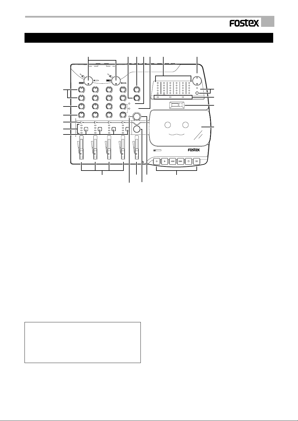
<Top Panel>
8
7
6
5
4
3
9
2/41/3
MIC IN
TRIM 2/4TRIM 1/3
EQ HI
0
+-
EQ LO
0
+-
MON MIX/
AUX
100
PAN
RL
1
4
REC TRK
3
2
1
1 2 3 4 MASTER
0
0
100
4
3
2
1
+-
+-
RL
LINE IN/INSERT
0
+-
0
+-
100
RL
4
3
2
1
11
AUX SEND
0
+-
0
+-
100
RL
432
4
REC TRKREC TRKREC TRK
3
2
1
1252 14
15
1. Input/playback level control faders
These faders have two functions:
One function controls the recording level. Input
levels applied to the INPUT jacks (fr ont or rear) are
controlled by this knob.
The other function controls the tape playback level
of each track. For more information on using these
faders, refer to the “Basic Recording” and “Basic
Playback Procedure” sections.
2. Master fader [MASTER]
This fader controls the output level from LINE OUT
L and R.
3. Record track select switch [REC TRK]
This switch is used to select recording tracks.
Press the switch repeatedly to select the desired
track. The track indicator (red) of the selected track
lights up to indicate that this track is REC READY.
To cancel the track selection, press the switch
repeatedly until none of the track indicators are lit.
<Note>
When the Track Down button is “ON,” the REC TRK switches
are disabled. Also, if the Auto Bounce button or Track Down
button is switched on and off while any one REC TRK switch
is set to REC READY state, the selected REC TRK switch
will be canceled. In this case, reselect the recording track
using the REC TRK switch.
4. Record track indicator
This indicator lights up in red to indicate that the
track is in the REC READY mode when you press
the REC TRK switch.
AUX RTN
MONITOR
10
AUX
MON MIX
Bounce
1213
AUX RTN
100
100
Track
Down
Auto
16
17 21
RL/MONO
MONITOR OUT
+
-
10
LINE OUT
WIDE PITCH
6
3
0
5
RL
+
6
3
–
+
0
NORMAL
FIX
5
-
10
4321
POWERRECNR
RESET
000
22
18, 19, 2
23
RL
RL
24
DOLBY B NR
multitracker
X-34
PAUSESTOPFFREC PLAY REW
5. Auto bounce indicator
This lights up in green when you press the Auto
Bounce button, indicating that the corresponding
track is selected as the auto bounce destination.
6. Pan pot knob [PAN]
When the AUX indicator is lit, use these knobs to
adjust the stereo imaging of channel signals routed
to the INPUT faders. When the MON MIX indicator
is lit, use these knobs to control the stereo imaging
of each track sound.
7. Monitor/AUX send level control knob [MON
MIX/AUX]
This knob enables you to adjust the level of the
channel signal for monitoring or to control the le vel
of the signal sent to the AUX bus.
8. Equaliz er control knobs [EQ HI, EQ LO]
The X-34 is equipped with a two-band, shelving-type
EQ. These knobs are used to adjust tonal quality of
the signals routed to the channel faders. The
following settings are available:
HI: Signals with a frequency of 10kHz will be boosted
and cut up to +/–12 dB.
LO: Signals with a frequency of 100Hz will be
boosted and cut up to +/–12 dB.
9. Trim knob
Use this knob to adjust the input level depending on
the sound source input to the r ear panel MIC IN jack
(1/4" or XLR).
This knob enables you to adjust from a signal that
ranges from line level to mic level.
5
Page 6

Model X-34 Owner’s Manual
10. AUX return knob [AUX RTN]
This knob allows you to adjust the input level of
processed signals from a connected external effect
unit. The level of both signals input to AUX RTN
L/MONO and R are adjusted equally.
11. Monitor master knob [MONITOR]
This knob allows you to adjust the final level of
monitoring signals, i.e., the headphone volume and
the level of signals output from the MONIT OR OUT
L/R jacks.
12. [AUX] indicator
This red indicator lights up when the channel MON
MIX/AUX knob functions as an AUX control.
13. [MON MIX] indicator
This red indicator lights up when the channel MON
MIX/AUX knob functions as a MON MIX control.
14. Track down on/off button [Track Down]
Pressing this button switches Track Down mode on
and off. When Track Down mode is switched on, the
Track Down indicator lights up. When Track Down
mode is switched off, the Track Down indicator turns
off. To select a recording track or perform Auto
Bounce (ping-pong), you need to cancel T rac k Down
mode.
15. Track Down indicator
The green Track Down indicator lights up when
Trac k Down mode is on. When you turn on the power
to the X-34, Track Down mode is automatically
engaged.
16. Auto bounce select button [Auto Bounce]
When Track Down mode is off, press this button to
engage Auto Bounce mode and select a ping-pong
destination track. This b utton is disabled when Track
Down mode is on. Pressing this button repeatedly
selects a track in the following or der: [1]->[2]->[3]
->[4]->[OFF]->[1]
<Note>
You cannot cancel ping-pong recording by pressing the
Auto Bounce button once the process has started.
17. Level meters
These five-dot indicator meters indicate the
recording/playback level.
During recording , the optimum level is 0 ~ 3 on this
meter.
18. Dolby B noise reduction indicator [NR]
This indicator lights up in green when you turn on
the DOLBY NR switch on the rear panel.
19. Record indicator [REC]
This indicator lights up in red when the X-34 is
placed in record mode. It also flashes in Punch in/
out rehearsal mode.
20. Power indicator [POWER]
This indicator lights up when you turn on the power.
21. Pitch control knob [WIDE PITCH]
Tape speed can be adjusted within the range of
–50% ~ +12%. This is normally set to the center
position.
Use this knob during the playback of recor ded music
to practice your performance at a slower speed.
This is also useful when you wish to overdub a
musical instrument that has slightly offset pitch, or
a vocalist who can’t quite hit the highest note. Pitch
control is disabled when the NORMAL FIX indicator
is lit.
22. Tape speed control/indicator [NORMAL FIX]
Press this switch to change the tape speed from 9.5cm/s
to 4.75cm/s.
The NORMAL FIX indicator lights up in
green, and the pitch control and Dolby B noise
reduction are disabled. Pressing this switch again
will restor e the Dolby and pitch control settings, and
the tape speed (9.6cm/s) will be restor ed. This switc h
is disabled during recording.
23. Tape counter/reset button [RESET]
Tape transport is metered and indicated here.
Press the r eset b utton to return the counter to [000].
24. Cassette lid/Cassette tray
Insert a cassette tape here.
Load or unload cassettes only when the transport is
stopped.
25. Transport control buttons
Play button [PLAY]
Press this button to start playback.
Stop button [STOP]
Press the [STOP] b utton to stop tape transport. The
tape transport buttons PLA Y, REC, REW and FF will
cancel and the tape will stop.
Fast forward button [FF]
Press this button to fast forward the tape at high
speed.
Rewind button [REW]
Press this button to rewind the tape at hight speed.
Recording button [REC]
While a record track indicator or indicators are lit
(red), press this button and the PLAY button
simultaneously to start recording. If you press the
PAUSE button prior to these buttons, the X-34 will
enter recor d standby mode and the tape will remain
stopped.
6
Page 7
<Note>
The REC button will be ineffective if the “cassette erase
prevention tab” is broken.
Pause button [PAUSE]
You press this button during playback or recording,
the tape will stop (the PLAY and RECORD buttons
will remain depr essed). If you press this b utton again,
stop mode will be canceled and playback or
recording will resume.
This button will not function during rewind or fast
forward operations.
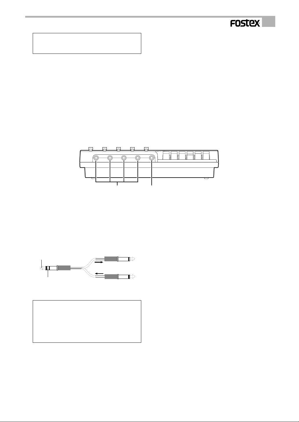
<Front panel>
12
Model X-34 Owner’s Manual
1. Line in/insert jack [LINE IN/INSERT 1, 2, 3, 4]
Line level sound sources are input here.
Input signals are sent only to the tracks selected by
the REC TRK switches on the corresponding
channels.
If a sound source input from the rear panel MIC IN
jack is to be processed, use these jacks to insert a
TIP (Return)
RING (Send)
compressor/limiter or other effect.
<Note>
Priority is always given to the LINE IN/INSER T jacks . You
cannot record one sound source from the MIC IN 1/3
jack and one from the LINE/INSERT 1 and 3 jacks (or
one from the MIC IN 2/4 jack and one from the LINE/
INSERT 2 and 4 jacks) onto the same track at the same
time. Refer to page 10 and 11 for more information.
2. Headphone jack [PHONES]
Plug in monitor headphones here.
7
Page 8
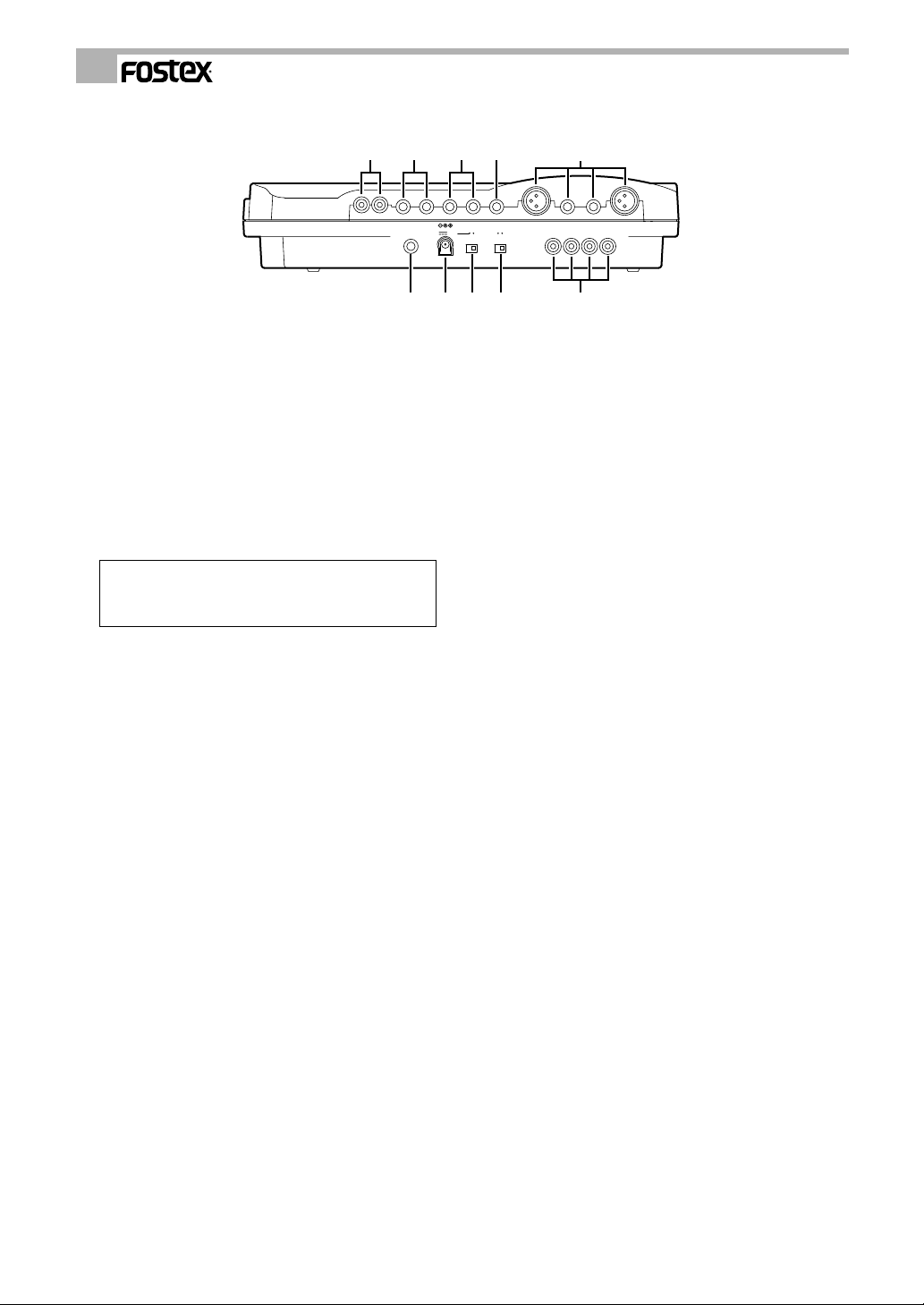
<Rear Panel>
Model X-34 Owner’s Manual
54321
1. Mic input jack [MIC IN 1/3, 2/4]
Plug in a microphone here.
You can input any signal, ranging from mic level to
line level devices, because the X-34 features a trim
knob for each input. Both XLR connectors (balanced)
and 1/4" jacks (unbalanced) are provided. Use the
one appropriate for your application.
The sound source input to MIC IN jack 1/3 is routed
to channels 1 and 3, and the inputs to MIC IN jack
2/4 are sent to channels 2 and 4.
<Note>
The XLR connector and 1/4" jack cannot be used
simultaneously to record onto the same track.
2. AUX Send jack [AUX SEND]
Connect this 1/4" jack to the input of an effects
processor. This jack outputs the signals selected and
adjusted by the MON MIX/AUX knobs.
3. AUX Return jacks [AUX RTN (L/MONO, R)]
Connect these 1/4" jacks to the output of an effects
processor. You can also use them as auxiliary inputs.
If a connected effects processor has a mono output,
connect the output to the L/MONO jack of the X-34.
(The right channel will receive the same signal.)
Adjust the level of processed signals using the AUX
RTN knobs on the top panel.
4. Monitor Out jacks [MONITOR OUT (L, R)]
Connect monitoring speakers and an amplifier (or
powered speakers) here to monitor the sound. These
1/4" jacks output the same signals as the PHONES
jack. Use the MONITOR knob on the top panel to
adjust the monitoring level.
5. Line out jacks [LINE OUT L, R]
These RCA pin jacks are connected to the master
recorder input connectors (L, R) for mixdown.
Adjust the output level using the MASTER fader.
PUNCH
IN/OUT
DOLBY NR
ON STANDBY
DC IN
ON
12V
OFF
10 9 8 7 6
6. Tape out jack [TAPE OUT 1, 2, 3, 4]
Signals from tracks 1-4 are output from these RCA
pin jacks.
These outputs can be sent to external mixers.
In addition, TAPE OUT 4 can also be used as the
SYNC OUT jack to send the sync signal from the
tape to an external MIDI sequencer.
7. Dolby B noise reduction on/off switch [DOLBY
NR ON/OFF]
This switch turns on Dolby B noise reduction.
For high quality recording and playback, we
recommended Dolby B.
If a tape recorded with Dolby B noise reduction is
played back, set this switch to ON. This switch is
disabled when the NORMAL FIX indicator is lit.
Dolby setting turns off automatically when the
NORMAL FIX indicator lights up.
8. Power switch [ON-STANDBY]
This switch turns on the power to the X-34. Even
when this is switched off (ST ANDBY), a small amount
of current continues to flow through the X-34.
Therefore, if the X-34 is not going to be used for a
long period of time, disconnect the AC adapter from
the wall socket.
9. DC IN connector [DC IN 12V]
Plug in the exclusive AC adapter packaged with X34 here.
10. Punch in/out jack [PUNCH IN/OUT]
Plug in the optional Foot Switch (Model 8051) for
punching in and out or rehearsal here.
TAPE OUT
1234
8
Page 9

Model X-34 Owner’s Manual
1
100
.
Basic Operation: “Let’s Record!”
Initial mode after the X-34 is powered on:
When you connect the AC adapter and turn on the power to the X-34, it automatically engages “Track Down mode,”
and the Track Down indicator lights up as shown below.
Please refer to the following “Initial setup of the X-34” section to r eset the X-34 before you proceed to the next session.
* For information on Track Down mode, refer to page 18.
+-
0
+-
+-
0
+-
+-
MONITOR
0
+-
100
-
10
RL
NR
AUX
Thesetwoindicatorslightup.
100
RL
MON MIX
100
RL
100
Track
RL
Down
432
Thisindicatorturnsoff
Initial setup of the X-34
After you complete a recor ding session, reset all knobs and switc hes on the X-34 to their initial settings befor e pr oceeding .
This will help you avoid unexpected problems r elated to switc h and knob settings being unsuitable for the ne xt r ecording.
In this manual, this state will be called the “initial setting.” The control panel switches and knobs should be set as
shown below.
Always return to this “initial setting” before proceeding to the next recording session.
Set the AUX RTN and
+-
+-
100
RL
AUX SEND
REC TRKREC TRKREC TRK
AUX RTN
MONITOR
AUX
MON MIX
Track
Down
Bounce
AUX RTN
100
100
Auto
MONITOR knobs to
the “0” position.
RL
RL/MONO
MONITOR OUT
+
-
10
LINE OUT
6
3
0
5
RL
RL
WIDE PITCH
+
6
3
–
+
0
NORMAL
FIX
5
-
10
4321
POWERRECNR
RESET
000
This indicator
lights up.
Center the pich
control knob.
Turn off the NORMAL
FIX switch. (The NORMAL FIX indicator
turns off.)
Reset the counter to
[000].
Set the TRIM knobs to
the “ ” position.
Set all EQ knobs to
center (“0”).
Lower all MON MIX/AUX
knobs to “0”.
Set all PAN knobs to
center.
Deselect all recording
tracks.
EQ HI
EQ LO
MON MIX/
AUX
PAN
This indicator
lights up.
2/41/3
MIC IN
TRIM 2/4TRIM 1/3
0
0
0
0
+-
+-
+-
0
0
+-
+-
100
100
RL
RL
1
4
4
REC TRK
3
3
2
2
1
1
0
0
+-
100
RL
432
4
4
3
3
2
2
1
1
1 2 3 4 MASTER
LINE IN/INSERT
Lower all faders
to the minimum.
Switch off Auto Bounce mode.
DOLBY B NR
multitracker
X-34
PAUSESTOPFFREC PLAY REW
Switch off Track Down mode.
(The Track Down indicator turns off.)
9
Page 10

Model X-34 Owner’s Manual
Remember the following before you start to record!
The X-34 includes jacks (or connectors) for musical instrument and mic inputs on the front and rear panels.
The functions of these input jacks (or connectors) are explained below:
Front panel LINE IN/INSERT jack
Normally, a line level sound source with a
1/4" type plug is connected here. (You
cannot plug in a microphone here.).
Signals applied to each input jack are
recorded on the track selected by the
corresponding REC TRK switch.
Therefore, by connecting four different
sound sources to these LINE IN/INSERT
jacks, you can record up to four tracks
simultaneously.
These jacks can also serve as an insert
point. For example, you can connect
various effects here , such as a compressor
for a mic input to a rear panel jack.
These jacks are used as insert points only
for sound sources input to the rear panel
(jack or XLR).
F or information on connecting effects, r efer
to page 25.
CHANNEL
Sound source A
Sound source B
Sound source C
Sound source D
REC TRK switch
REC TRK switch
REC TRK switch
REC TRK switch
1234
Sound source A on the track
specified by REC TRK switch 1
Sound source B on the track
specified by REC TRK switch 2
Sound source C on the track
specified by REC TRK switch 3
Sound source D on the track
specified by REC TRK switch 4
Rear panel MIC IN (1/3, 2/4) jack
Microphones are generally plugged in
here.
Use the trim knob provided for each input
to adjust the input level to match the output
level of the connected sound source.
The Trim knobs attenuate the input level
to accommodate inputs ranging from mic
to line level.
Both 1/4" jacks and XLR connectors are
provided, allowing for many types of sound
sources.
However, remember that priority is given
to the 1/4" jack. If it is being used, the
XLR connectors are ineffective.
Unlike the front panel input jacks, signals
input to MIC IN 1/3 will be routed to
channels 1 and 3 , and signals input to MIC
IN 2/4 will be routed to channels 2 and 4.
The REC TRK switch setting determines
which tracks will be recorded.
REC TRK switch
REC TRK switch
REC TRK switch
REC TRK switch
CHANNEL
DC IN
12V
MIC IN jack 2/4 MIC IN jack 1/3
4321
DOLBY NR
ON STANDBY
ON
OFF
or or
Sound source A
TAPE OUT
1234
Sound source B
Sound source A on the track
specified by REC TRK switch 4
Sound source B on the track
specified by REC TRK switch 3
Sound source A on the track
specified by REC TRK switch 2
Sound source B on the track
specified by REC TRK switch 1
10
Page 11

Model X-34 Owner’s Manual
Y
<Using both MIC IN jack and LINE IN/INSERT jack>
Keep the following information about the MIC IN and LINE IN/INSERT jacks in mind when recording sound
sources using both types of input jacks.
The front panel LINE IN/INSERT jack has priority. For example, if you attempt to input different sound sources
(Sound source A, Sound source B) simultaneously from the front panel LINE IN/INSERT jack 1 and the rear panel
MIC IN jack 1/3, priority will be given to the LINE IN/INSERT jack 1 to send the signal to channel 1, and the signal
from the MIC IN jack 1/3 will be sent to only channel 3.
Since Sound source A is routed to channel 1 and Sound source B is routed to channel 3, selecting a recording track
using the corresponding REC TRK switches enables you to record Sound sources A and B simultaneously. The
same applies to LINE IN/INSERT jack 3 and MIC IN jack 1/3.
SoundsourceBwillberecordedtoa
trackselectedbytheRECTRKswitch
onchannel3.
Channel3
PUNCH
IN/OUT
DOLBY NR
ON STANDBY
DC IN
ON
12V
OFF
TAPE OUT
MICINjack1/3(SoundsourceB)
Channel1
1234
SoundsourceAwillberecordedtoa
trackselectedbytheRECTRKswitch
onchannel1.
Channel1
LINEIN/INSERTjack1(SoundsourceA)
If you connect Sound sources A and B to LINE IN/INSERT jacks 1 and 3, and Sound source C to MIC IN jack 1/3,
Sound source C will be ignored and cannot be recorded simultaneously. (The same applies to LINE IN/INSERT
jacks 2 and 4 and MIC IN jack 2/4.)
SoundsourceBwillbe
recordedtoatrackselectedbytheRECTRKswitch
onchannel3.
SoundsourceCisnotrecorded.
SoundsourceAwillbe
recordedtoatrackselectedbytheRECTRKswitch
onchannel1.
Channel3
Channel1
Channel1
Channel3
DOLBY NR
ON
OFF
TAPE OUT
1234
LINEIN/INSERTjack3(SoundsourceB)
MICINjack1/3(SoundsourceC)
LINEIN/INSERTjack1(SoundsourceA)
11
Page 12

Model X-34 Owner’s Manual
Basic Recording - 1 (Recording from the front panel LINE IN/INSERT jack)
First, let’s connect your musical instrument and try recording on a specific track.
In the following example, a synthesizer will be recorded on track 1. This and other explanations assume an AC adapter
is connected to the X-34 and the X-34 is powered on.
* Before proceeding to the next step, set the X-34 to its “initial settings” as explained on page 9.
Also, make sure that the Track Down indicator is turned off.
493
10
11
7,14
2/41/3
MIC IN
TRIM 2/4TRIM 1/3
EQ HI
0
+-
EQ LO
0
+-
MON MIX/
AUX
9
100
PAN
RL
1
4
REC TRK
3
2
1
0
0
+-
+-
0
0
+-
+-
100
100
RL
RL
4
4
3
3
2
2
1
1
AUX RTN
AUX SEND
AUX RTN
0
100
+-
MONITOR
0
100
+-
AUX
MON MIX
100
Track
Down
RL
432
4
REC TRKREC TRKREC TRK
3
Auto
Bounce
2
1
8
1 2 3 4 MASTER
LINE IN/INSERT
2,8
Keyboard
1. Lift the cassette tray lid and load the cassette
into the cassette tray.
If a previously-recorded tape is being used, check
that the rear side erasur e pr evention tab has not been
broken off.
If it is, cover the hole with a piece of scotchtape.
2. Use an instrument cable to connect the
synthesizer output to the front panel LINE IN/
INSERT jack 1.
3. Plug the headphones into the PHONES (
jack on the front panel, or connect the monitor
speaker system to the MONITOR OUT jack on
the rear panel.
4 Switch ON the Dolby B noise reduction switch.
5. Press the PLAY button to advance the tape a
few seconds.
This will wind past the leader at the head of the
3
Headphones
)
Monitor speakers
RL/MONO
MONITOR OUT
+
-
LINE OUT
WIDE PITCH
6
3
0
5
10
RL
+
6
3
–
+
0
NORMAL
FIX
5
-
10
4321
POWERRECNR
RESET
000
6
The MON MIX
7
indicator lights up.
RL
RL
1
DOLBY B NR
multitracker
X-34
PAUSESTOPFFREC PLAY REW
12
5 15 13
recording tape. If a used tape is not completely
rewound, press the REW button to wind to the
beginning and repeat this step.
6. After you wind past the leader tape, press the
RESET button to set the counter to [000].
7. Press the REC TRK switch 1 once to place trac k
1 in REC READY mode.
The recor d trac k indicator 1 will light up in red, and
the MON MIX indicator will light up.
<Note>
You can, of course, record the sound source connected
to LINE IN/INSERT jack 1 to any track other than tr ack 1
using REC TRK switch 1 to select the desired track.
12
Page 13

<Note>
When Track Down is “ON,” the REC TRK switches are
disabled. Also, if the Auto Bounce button or Track Down
button is switched on and off while any one REC TRK
switch is set to REC READY state, the selected REC
TRK switch will be canceled. In this case, reselect the
recording track using with the REC TRK switch.
8. While playing the synthesizer, gradually raise
the channel 1 input/playback level fader.
As the fader is raised, the level meter 1 will start to
blink.
Adjust the recording level by raising the input/
playback level fader to a point where the meter [3]
blinks at maximum sound volume.
9. You can adjust the headphone or monitor
speaker sound volume by turning the
MONITOR knob, and the channel 1 MON MIX/
AUX knob.
10. Use the EQ knobs on channel 1 to adjust the
tone.
11. Position the monitor sound image using the
channel 1 PAN knob.
<Note>
If you had selected a track other than track 1 as the
recording destination, use the MON MIX/AUX knob and
PAN knob of the corresponding track channel. For
example, if the sound source is input at LINE IN/INSER T
1 and to be recorded to track 2, use the MON MIX/AUX
knob and the PAN knob on channel 2.
Model X-34 Owner’s Manual
12. After adjusting the recording level and tone,
press the REC button (the PLAY button will also
depress) to start recording.
The REC indicator lights up in red.
13.When you finish recording, press the STOP
button.
Recording will be canceled (the REC indicator turns
off).
14. Press REC TRK switch 1 repeatedly to turn off
the record track indicator.
15. Press the REW button and rewind the tape to
counter [000].
Try recording on tracks 2-4 in the same way.
13
Page 14

Model X-34 Owner’s Manual
Basic Recording - 2 (Recording with the rear panel MIC IN jack)
This section describes how to record a vocal on track 1 by plugging a microphone into the rear panel MIC IN jack 1/3.
* Before proceeding to the next step, remember to reset the X-34 to its “initial settings.” (See page 9.)
Also, make sure that the Track Down indicator is turned off.
319
AUX RTN
MONITOR
AUX
MON MIX
Bounce
RL/MONO
AUX RTN
100
100
Track
Down
Auto
10
2/41/3
MIC IN
8
EQ HI
EQ LO
MON MIX/
AUX
9
PAN
6
0
0
+-
+-
0
0
+-
+-
100
100
RL
RL
1
4
REC TRK
3
2
1
1 2 3 4 MASTER
4
3
2
1
LINE IN/INSERT
4
3
2
1
AUX SEND
TRIM 2/4TRIM 1/3
0
0
+-
+-
0
0
+-
+-
100
100
RL
RL
432
4
REC TRKREC TRKREC TRK
3
2
1
7
Headphones
1. Plug a mic into the rear panel MIC IN jack 1/3
(1/4" or XLR).
2. Make sure that the Track Down indicator is
turned off.
<Note>
When Track Down is “ON” , the REC TRK switches are
disabled.
3. Switch ON the Dolby B noise reduction switch.
4. If this is a new song, load a cassette in the
transport and advance the tape to recording
start position as previously described.
5. Reset the counter to [000] by pressing the
RESET button.
6. Place track 1 in REC READ Y mode b y pressing
REC TRK switch 1.
Record track indicator 1 lights up in red.
The signal from MIC IN jack 1/3 is also routed to
channel 3.
Monitor speakers
RL
RL
LINE OUT
MONITOR OUT
+
6
3
0
5
-
10
RL
DOLBY B NR
multitracker
11
7. Raise the channel 1 input/playback level
8. Adjust the recording level with the Trim
9. The headphone and monitor volume can
10. Use the EQ knobs on channel 1 to adjust the
11. After you adjust the recording level and tone,
WIDE PITCH
+
6
3
– +
0
NORMAL
FIX
5
-
10
4321
POWERRECNR
RESET
000
6
The MON MIX indicator lights up.
5
4
<Note>
If the Auto Bounce button
is switched on and off
X-34
PAUSESTOPFFREC PLAY REW
while any one REC TRK
switch is set to REC
READY state , the selected
REC TRK switch will be
canceled. In this case,
reselect the recording
122
track using with the REC
TRK switch.
If you also select track 3 by pressing the REC TRK
switch on channel 3, the same signal can be recor ded
to tracks 1 and 3.
fader to the position shown right.
1/3 knob while talking into the
microphone so that segments 0 - 3 on
the level meter light up.
be adjusted using the MONITOR knob
1
and the channel 1 MON MIX/AUX knob.
tone.
start recording by pressing the REC button.
(The PLAY button also depresses.)
14
Page 15

Model X-34 Owner’s Manual
12.When you finish recording, press the STOP
button to stop the tape transport and press the
REC TRK switch 1 repeatedly to deselect the
recording track.
<NOTE>
If you connect a microphone to MIC IN jack 2/4, the signal
is routed to channels 2 and 4 (although you can use the
REC TRK switch to route the signal to an y desired trac k).
The MON MIX indicator turns off, and the AUX
indicator lights up.
Basic Playback Procedure
Let’s play back and listen to the recorded sound.
This procedure assumes different sounds have been recorded to tape on tracks 1 - 4.
* Before proceeding to the next step, reset the X-34 to its “initial settings.” (See page 9.)
Make sure that the Track down indicator is turned off.
Track
Down
Bounce
RL/MONO
AUX RTN
100
100
Auto
Monitor speakers
RL
RL
LINE OUT
MONITOR OUT
+
6
3
0
5
-
10
RL
WIDE PITCH
+
6
3
– +
0
NORMAL
FIX
5
-
10
4321
POWERRECNR
RESET
000
25
2/41/3
MIC IN
EQ HI
EQ LO
MON MIX/
AUX
PAN
4
0
0
+-
+-
0
0
+-
+-
100
100
RL
RL
1
4
REC TRK
3
2
1
4
4
3
3
2
2
1
1
AUX SEND
TRIM 2/4TRIM 1/3
AUX RTN
0
0
+-
+-
0
+-
100
RL
MONITOR
0
+-
AUX
MON MIX
100
RL
432
4
REC TRKREC TRKREC TRK
3
2
1
The MON MIX indicator lights up.
3
1
1 2 3 4 MASTER
LINE IN/INSERT
Headphones
1. Rewind the tape to counter [000].
2. Switch ON the Dolby B noise reduction switch.
3. Press the PLAY button to play back the tape.
The MON MIX indicator rights up.
4. Gradually turn the MON MIX/AUX knobs for
each channel to adjust the output of each track.
Adjust the PAN knobs for each channel to achieve
the proper stereo image.
DOLBY B NR
multitracker
X-34
PAUSESTOPFFREC PLAY REW
3
5. Use the MONITOR knob to adjust the overall
monitor volume.
<Note>
If you monitor with headphones for several hours, do not
raise the MONITOR knob too high. Otherwise, you could
damage your hearing. Take a break occasionally to give
your ears a rest.
You can also use Tr ack Down mode to play back the
recording. Refer to page 18 for more information.
15
Page 16

Model X-34 Owner’s Manual
Multitrack Recording
You should now have a good understanding of the basic recording and playback operation of the X-34.
Now let’s try the X-34’s multitrack recording functions.
The following sections explain overdubbing, which is a fundamental function in multitrack recording, and also the
mixdown process, in which the sound recorded to four tracks is mixed and copied (dubbed) to a master recorder.
Overdubbing
Overdubbing is a pr ocess that enables you to “layer” recorded sounds. This technique involves listening to (monitoring)
a previously-recorded track while recording new performance to a different track.
For example, the rhythm section (drum machine) might be recorded on track 1. While you listen to the drum track, you
record an electric bass to track 2. Thus, different sounds are recorded in “layers” on the four separate tracks.
In the example below, we assume that a drum machine is recorded on track 1. We then over dub an electric bass on tr ack
2, a keyboard on track 3, and a vocal on track 4.
<Overdubbing Electric Bass in Track 2 While Listening to the Drum Track>
While playing back and
listening to Track 1 (drum
machine), Track 2 (electric
bass) and Track 3 (keyboard)
overdub the vocal to Track 4.
Track 4 (Vocal)
Track 3 (Keyboard)
Track 2 (E. bass)
Track 1 (Drum machine)
While playing back and
listening to Track 1 (drum
machine), overdub the
electric bass to Track 2.
Track 2 (E. bass)
Track 1 (Drum machine)
While playing back and
listening to Track 1 (drum
machine) and Track 2
(electric bass), overdub the
keyboard to Track 3.
Track 3 (Keyboard)
Track 2 (E. bass)
Track 1 (Drum machine)
*
Before starting to overdub, refer to “Basic Playback Procedure” and practice the electric bass track while listening to drums on track 1.
* Before you start, set the X-34 to its initial settings. (See page 9.)
4,7,1 1
6
MIC IN
EQ HI
EQ LO
MON MIX/
AUX
9
PAN
8
7
0
0
+-
+-
0
0
+-
+-
100
100
RL
RL
1
4
4
REC TRK
3
3
2
2
1
1
1 2 3 4 MASTER
LINE IN/INSERT
36
2/41/3
AUX SEND
TRIM 2/4TRIM 1/3
AUX RTN
0
0
+-
+-
0
+-
100
RL
4
3
2
1
MONITOR
0
+-
AUX
MON MIX
100
RL
432
4
REC TRKREC TRKREC TRK
3
2
1
5
Bounce
AUX RTN
100
100
Track
Down
Auto
Monitor speakers
RL
RL/MONO
MONITOR OUT
+
6
3
0
5
-
10
RL
DOLBY B NR
9
RL
LINE OUT
RESET
000
multitracker
X-34
12 10
WIDE PITCH
+
6
3
–
+
0
NORMAL
FIX
5
-
10
4321
POWERRECNR
1
PAUSESTOPFFREC PLAY REW
2,5
Headphones
16
Page 17

Model X-34 Owner’s Manual
1. Rewind tape to its starting position ([000]) for
recording.
2. Plug the electric bass into front panel LINE IN/
INSERT jack 2. (You can use any available LINE
IN/INSERT jack.)
<Note>
This is the simplest way to record a bass. You can also
use an amplifier or a direct-input box to create different
sounds.
3. Switch ON the Dolby B noise reduction switch.
Adjusting the Recording Level and Practicing your
performance
Before overdubbing, practice and adjust the level of the
electric bass by listening to the prer ecor ded trac k sound.
4. Press REC TRK switch 2 to select track 2 as a
recording track.
Track 2 enters REC READY mode.
5. While playing the electric bass, adjust the
recording level by gradually raising the channel
2 input/playback level fader.
The track 2 level indicator lights up.
6. Adjust the overall headphone or monitor
volume using the MONITOR knob and the
channel 2 MON MIX/AUX knob.
Overdubbing T ake
7. Make sure that the record track indicator on
channel 2 is lit. Otherwise, press the REC TRK
switch 2 to set track 2 in REC READY mode.
8. Adjust the placement of each channel in the
stereo image using the PAN knobs.
9. Start recording your performance by pressing
the REC button. (The PLAY button also
depresses.)
While listening to the track 1 playback, play the
electric bass and overdub it to track 2.
Adjust the track 1 sound (drum machine) using the
channel 1 MON MIX/AUX knob.
10. When you have finished overdubbing, press
the STOP button to stop the tape transport.
11. Press REC TRK switch 2 repeatedly to turn off
the record track indicator.
12. Rewind the tape to counter [000] and play back
sound on tracks 1 and 2. If you have questions,
please refer to “Basic playback Procedure” on
page 15.
In the same manner, overdub on tracks 3 and 4.
17
Page 18

Model X-34 Owner’s Manual
ff.
Mixdown (Track Down mode)
After all four tracks have been recorded, the next step is mixdown (Track Down mode).
Mixdown is the process of adjusting the sound volume and stereo image of what you recorded on tracks 1 - 4, and as a
final process, mixing them to two channels (stereo) and dubbing (copying) it to a master recorder.
When you switch on the Track Down button, the X-34 enters Track Down mode.
Track
Down
* Before proceeding to the next step, set the X-34 to its “initial settings.” (See page 9.)
Make sure that the Track Down indicator is turned off.
You can use Track Down mode to play back a demo tape or recorded tape. In Track Down
mode, all track sounds are routed to the corresponding channel level faders.
Monitor speakers Master Recorder
49
AUX RTN
MONITOR
AUX
MON MIX
Track
Bounce
RL/MONO
MONITOR OUT
AUX RTN
+
6
3
0
100
100
Down
Auto
5
-
10
DOLBY B NR
2/41/3
MIC IN
EQ HI
7
EQ LO
MON MIX/
AUX
PAN
7
7
0
0
+-
+-
0
0
+-
+-
100
100
RL
RL
1
4
REC TRK
3
2
1
1 2 3 4 MASTER
4
3
2
1
LINE IN/INSERT
4
3
2
1
AUX SEND
TRIM 2/4TRIM 1/3
0
0
+-
+-
0
0
+-
+-
100
100
RL
RL
432
4
REC TRKREC TRKREC TRK
3
2
1
Headphones
1. Connect the X-34 LINE OUT L, R jacks to the
master recorder inputs (L, R).
2. Insert a tape in the master recorder and wind
the tape to its start point.
3. Make sure that the overdubbed tape is inserted
in the X-34, and wind to the beginning of the
recorded tracks.
4. Switch ON Dolby B noise reduction.
Adjust the Output Level/Recording Level
5. Set master recorder to record-standby.
Typically, you will press the PAUSE button on the
master recorder so that the master recorder level
meters will respond. Because master recorders from
1 2,5,8,11,12
RL
RL
LINE OUT
WIDE PITCH
+
6
3
–
+
0
NORMAL
FIX
5
-
10
RL
4321
POWERRECNR
RESET
000
TrackDownindicatorturnso
6
6
3
multitracker
X-34
PAUSESTOPFFREC PLAY REW
3,1 1
6,1 1 10,12
different manufactur ers work dif fer ently , please r efer
to the operating manual for the master recorder.
6. Press the X-34 Track Down button, then the
PLAY button to play the tape from the
beginning.
The Track Down indicator lights up.
7. Use the channel faders to adjust the output
level of each track (the level balance between
tracks), and use the channel PAN knobs to
adjust the left and right output balance, and
the channel EQ knobs to adjust tonal color.
Adjust the overall output level using the
MASTER fader.
8. Adjust the recording level on the master
recorder so that its level meter indicates the
optimum level.
18
Page 19

Model X-34 Owner’s Manual
<Note>
There are no fixed rules for determining the playback
sound image position of each track using the PAN knob
at mixdown.
This is where your creativity comes in. Try for a sound
that pleases you!
Final Mixdown
11. First place the master recorder in record mode,
then press the PLAY button on the X-34.
12. When you finish the mixdown, stop both the
X-34 and the master recorder.
9. You can adjust the headphone or monitor
speaker volume using the MONITOR knob.
10. When you finish making these settings, rewind
the tape to the beginning.
Advanced Operation
In the “Basic Operation” section, you learned about the X-34’s basic recording/playback and multitrack recording
capabilities. This section explains “Punch in/out recording,” “Ping-pong recording,” “Tape sync” and “How to use
the effects.”
Punch In/Out Recording
“Punching in and out refers to recording “over” a section of an already-recorded tape.
You can use this technique to fix mistakes or improve previously-recorded takes.
Also, you can use the X-34’s rehearsal mode to practice and adjust the recording level and the punch in/out timing
before you actually record the take.
<NOTE>
To punch in, play the tape to the star t of the section you want to re-record and, at a point between phrases and preferably on a beat,
enter recording mode and record new material.
The process of returning again to playback mode is called punching out.
An optional foot switch (Fostex model 8051) is required to punch in and out on the X-34.
Punching in and out is illustrated below.
Track 4
Track 3
Re-recording section
Playback all tracks
Step on the foot switch
once upon arriving at the
punch in point.
* Before proceeding to the next step, set the X-34 to its “initial settings” as explained on page 9.
Also, make sure that the Track Down indicator is turned off.
T rack 2 only is recorded and other trac ks remain
in playback.
Track 2
Track 1
All tracks in playback.
Step on the foot switch
again where you wish to
punch out point.
Tape travel
19
Page 20

Model X-34 Owner’s Manual
For example, part of the electric bass recorded on track 2 will be replaced during overdubbing.
We assume that you have already loaded a prerecorded tape in the X-34 and rewound to the beginning of the recorded
tracks.
4,12
Monitor speakers
66
RL
AUX RTN
MONITOR
AUX
MON MIX
Bounce
RL/MONO
MONITOR OUT
AUX RTN
+
6
3
0
100
100
Track
Down
Auto
5
-
10
RL
DOLBY B NR
2/41/3
MIC IN
EQ HI
EQ LO
MON MIX/
AUX
PAN
8
0
0
+-
+-
0
0
+-
+-
100
100
RL
RL
1
4
REC TRK
3
2
1
1 2 3 4 MASTER
4
3
2
1
LINE IN/INSERT
4
3
2
1
AUX SEND
TRIM 2/4TRIM 1/3
0
0
+-
+-
0
0
+-
+-
100
100
RL
RL
432
4
REC TRKREC TRKREC TRK
3
2
1
1,9,10,14,15
Foot switch
RL
LINE OUT
POWERRECNR
RESET
000
multitracker
X-34
WIDE PITCH
+
6
3
–
+
0
NORMAL
FIX
5
-
10
4321
4
The MON MIX
indicator lights up.
2
PAUSESTOPFFREC PLAY REW
3
5
3,5
Headphones
13
4
16
7 1 1,16
1. Plug the optional foot switch into the PUNCH
IN/OUT jack.
2. Advance the tape to a point just before where
new material is to be inserted.
3. Plug the electric bass into the front panel LINE
IN/INSERT jack 2.
Rehearsing the Punch In
4. Make sure the Track Down indicator is turned
off, then place track 2 in REC READY mode by
pressing the REC TRK switch 2.
The REC TRK 2 indicator on channel 2 lights up,
and the REC indicator flashes slowly.
5. Raise the channel 2 input/playback level fader
to adjust the recording level while you play the
electric bass.
6. You can adjust the overall headphones or
monitor volume using the MONIT OR knob and
the channel 2 MON MIX/AUX knob.
7. Press the PLAY button to start playback.
20
8. Use the MON MIX/AUX and PAN knobs to adjust
the output and stereo image for each track.
9. Step on the foot switch when you reach the
punch-in point and play your part.
The REC indicator flashes faster. Only track 2 will
enter input monitor mode. This means that you can
hear the new bass part on track 2 along with the
playback sound from other tracks.
10. Step on the foot switch again when you wish
to punch out.
The REC indicator flashes more slowly, and the
X-34 enters input monitoring mode.
11. When you finish rehearsing, stop the transport
by pressing the STOP button and rewind the
tape.
Because no recording takes place during rehearsal,
repeat the pr ocess up to this point to set the r ecording
level and get your playing technique down, and also
practice the timing of the punch in and out. Punching
in and out in tempo (on strong beats) can help
camouflage the edit.
Page 21

Model X-34 Owner’s Manual
Recording the Punch-in
15. Step on the foot switch again at the point you
wish to punch out.
12. Make sure that track 2 is in REC READY mode.
(If not, press the REC TRK switch on channel
2 to select track 2).
Record track indicator 2 on c hannel 2 lights up and
the REC indicator flashes slowly.
13.Press the REC button to start the tape from
The REC indicator again begins to flash fast. The
recording mode will be canceled and all tracks will
be in the playback mode.
16. Upon completing the punch-in, press the STOP
button to stop the transport, rewind the tape
and listen to the results of your performance.
slightly before the punch-in point.
The REC indicator flashes faster.
It might be a good idea to play the bass in unison
with the playback to get in sync for the punch in.
14. Step on the foot switch at the punch in point.
Tr ack 2 will enter input monitor mode and r ecording
mode (the REC indicator lights up continuously).
The X-34 starts recording the electric bass on track
2. You can monitor your performance along with the
playback from other tracks.
<NOTE>
Skill is required to match the newly replaced sound level
to the pre-recorded sound.
Try the following method:
1. While playing the track you want to punch in, adjust
the input/playback level fader so that the meter
indicates 0 - 3.
2. While rehearsing the new musical instrument, adjust
the input/playback level fader so that the level meter
lights up to the same degree as the playback tracks.
Ping-pong Recording (Using the Auto Bounce Function)
In a multitracker, the four tracks can be used effectively to record many sound sources. However, if you record on all
four tracks, you may run out of tracks for other musical instruments or vocals. However, there is a method for clearing
tracks to allow for more recording. In this method, called “ping-pong recording,” playback sounds from a multiple
number of recorded tracks are mixed and recorded to an empty track.
Ping-pong recording effectively lets you record a greater number of instruments or other sound sources.
<For example, you can record six tracks using ping-pong recording shown in the schematic below>
Record sound sources A, B,
C to tracks 1 ~ 3
Track 4
Track 3 (sound source C)
Track 2 (sound source B)
Track 1 (sound source A)
Ping pong sound sources
A, B, C to track 4
Sound source A, B, C
Record new sounds D and
E to tracks 1 and 2
Sound source A, B, C
Sound source E
Sound source D
Ping pong sound sources
D and E to track 3
Sound source A, B, C
Sound source D, E
The X-34 utilizes an “Auto Bounce” ping-pong recording function.
The Auto Bounce function can greatly simplify ping-pong recording.
Each time you press the Auto Bounce button, these indicators light up
in the following order: 1 -> 2 -> 3 -> 4 -> OFF -> 1...
1
4
4
REC TRK
3
3
2
2
1
1
432
4
4
3
2
1
REC TRKREC TRKREC TRK
3
Auto
Bounce
2
1
Use this button to turn Auto Bounce mode on or off. (Please note that
this button is disabled if the Track Down indicator is on.)
Record new sound source
F and G to tracks 1 and 2
Sound source A, B, C
Sound source D, E
Sound source G
Sound source F
21
Page 22

Model X-34 Owner’s Manual
<Beware of oscillation during ping-pong recording>
When you ping-pong record between adjacent tracks (such as from track 2 to track 1 or 3), oscillation may result if the gain control is
raised too high. If this happens, immediately stop recording. If you are monitoring with headphones or an external monitor while the
sound is oscillating, it could cause damage your hearing. After y ou stop recording, reduce the output (using the MON MIX/AUX knobs)
to a suitable level, then resume recording. Also, avoid repeated ping-pong recording or the sound quality may deteriorate.
In this section, the sounds recorded on tracks 1 - 3 will mixed and ping-pong recorded to track 4.
* Before proceeding to the next step, set the X-34 to its “initial settings” as explained on page 9.
Also, make sure that the Track Down indicator is turned off.
Monitor speakers
27
RL
RL
AUX RTN
MONITOR
AUX
MON MIX
Bounce
RL/MONO
MONITOR OUT
AUX RTN
100
100
Track
Down
Auto
LINE OUT
WIDE PITCH
+
6
3
0
5
-
10
RL
+
6
3
–
+
0
NORMAL
FIX
5
-
10
4321
POWERRECNR
RESET
000
1
The indicator lights up.
2/41/3
MIC IN
EQ HI
EQ LO
MON MIX/
AUX
PAN
3
3
0
0
+-
+-
0
0
+-
+-
100
100
RL
RL
1
4
REC TRK
3
2
1
4
4
3
3
2
2
1
1
AUX SEND
TRIM 2/4TRIM 1/3
0
0
+-
+-
0
0
+-
+-
100
100
RL
RL
432
4
REC TRKREC TRKREC TRK
3
2
1
1 2 3 4 MASTER
LINE IN/INSERT
1. Insert the tape and rewind to the beginning of
the recorded tracks.
2. Switch ON Dolby B noise reduction.
3. Press the Auto Bounce button repeatedly until
the Auto Bounce indicator 4 lights up in green.
Track 4 is now specified as the ping-pong
destination.
4. Press the PLAY button to play back the tape.
5. Adjust tracks 1 -3 playback level using the
channel 1 - 3 input/playback level faders.
<Note>
If you do not want to include a particular track in the Auto
Bounce, lower its input fader to minimum.
DOLBY B NR
multitracker
X-34
PAUSESTOPFFREC PLAY REW
65
Headphones
9
8 10
4
6. Adjust the track 4 recording level using the
channel 4 input/playback level fader.
7. Adjust the headphone or monitor volume using
the MONITOR knob.
8. When you finish adjusting the recording level,
rewind the tape to the beginning of the tracks.
9. Press the REC button to start recording.
The REC indicator lights up.
10. When you finish ping-pong recording, stop the
transport by pressing the STOP button.
Auto Bounce mode is canceled and Track Down
mode is automatically selected. The REC indicator
turns off. Rewind the tape and listen to the pingpong recorded sound.
Subsequently, you can overdub new performances
to tracks 1 - 3.
22
Page 23

Model X-34 Owner’s Manual
For monitoring, the PAN knob of the channel to which ping-pong is carried out is fully left (L) or right (R). The other channel PAN knobs
are fully rotated in the opposite direction. Using these settings, you can separately monitor the sound of the ping-pong receiving
channel (track 4 in this example) and the ping-pong source channels (tracks 1 - 3 in this example).
<Notes on Auto Bounce recording>
<Monitoring>
When Track Down is “ON,” the Auto Bounce button is disabled. Also, if the Auto Bounce button is switched on and off while any one
REC TRK switch is set to REC READY state, the selected REC TRK switch will be canceled. Also, pressing any REC TRK switch while
Auto Bounce mode is “ON,” will cancel Auto Bounce mode.
Tape Sync
Tape sync is a great function for synchronizing the automatic performance of a sequencer and drum machine (MIDI
sound source) to a performance recorded on tape.
Here’s why this function is so handy:
1) The number of tracks can be economized because automatic performances of MIDI equipment need not be recorded to tape.
2) Because the dynamic sound of an electronic musical instrument (synthesizer, drum machine, etc.) can be mixed down directly, you
can obtain a higher quality sound.
3) Flexible editing, such as overdubbing an automated performance or replacing a drum machine track, is made possible.
* In order to carry out tape sync, it is necessary to reserve track 4 for recording and playback of a sync signal called the “FSK signal.”
The FSK signal is a modulation into sound of the performance tempo information output from a sequencer or drum machine, called
the “MIDI clock.” This is one type of MIDI signal. A track recorded with this signal serves as the “conductor’s baton,” so to speak.
When this signal is played back and sent to the sequencer or drum machine, the MIDI equipment starts performing in sync with the
tempo of this signal.
* Some sequencers and drum machines cannot independently input or output FSK signals. When using this type of equipment, a
MIDI/FSK converter is required. For details, please refer to the MIDI equipment operating manual.
<NOTES>
After you record the FSK signal to track 4, be sure to de-select track 4 and completely retard the channel 4 fader before proceeding to
<IMPORTANT>
mixdown.
23
Page 24

Model X-34 Owner’s Manual
Recording a sync signal
1. Connect the FSK output of the MIDI/FSK
converter to the LINE IN/INSERT 4 jack of the
X-34, and connect a MIDI sequencer to the MIDI/
FSK converter via MIDI.
2. Press the REC TRK 4 switch to select track 4
for recording.
3. Start playing the sequencer and adjust the
recording level of sync signal using the
channel 4 fader.
<Tape Sync connection example>
Record other musical instruments first, then synchronize the MIDI sound source with
the recordings to mix down the sound via the mixing console as shown below.
MIDI Sound Source
MIDI IN
FSK Converter
FSK signal
4. Stop the sequencer.
5. Press the REC button on the X-34 to start
recording on track 4.
6. Star t playing the MIDI sequencer.
The sync signal will be recorded on track 4.
It is recommended that you r ecor d the sync signal
for a duration that exceeds the song. You cannot
extend the sync signal recording later.
Master Recorder
Mixing Console
(e.g., Fostex MN04)
TAPE OUT 4
EQ HI
0
+-
EQ LO
0
+-
MON MIX/
AUX
100
PAN
RL
1
4
REC TRK
3
2
1
1 2 3 4 MASTER
0
0
100
4
3
2
1
MIC IN
+-
+-
RL
LINE IN/INSERT
2/41/3
TRIM 2/4TRIM 1/3
0
+-
0
+-
100
RL
4
3
2
1
AUX SEND
0
+-
0
+-
100
RL
432
4
REC TRKREC TRKREC TRK
3
2
1
AUX RTN
MONITOR
AUX
MON MIX
Track
Down
Bounce
RL/MONO
MONITOR OUT
AUX RTN
100
100
Auto
Before starting mixdown, lower the channel 4 fader to
the minimum level and de-select all recording tracks.
RL
RL
LINE OUT
WIDE PITCH
+
6
3
0
5
-
10
RL
DOLBY B NR
multitracker
+
6
3
–
+
0
NORMAL
FIX
5
-
10
4321
POWERRECNR
RESET
000
X-34
PAUSESTOPFFREC PLAY REW
24
Page 25

Model X-34 Owner’s Manual
Applying Effects
You may apply effects to the X-34 signals during mixdown by connecting an external effects processor in line between
the AUX SEND and AUX RTN connectors on the rear panel. The MON MIX/AUX knobs are used to adjust the amount
of signal sent to the effects processor. The processed signals are returned to the X-34 via the AUX RTN connectors and
mixed with the dry (no effect) sound. After adjusting the balance between the dry and wet sounds (using the AUX RTN
knob), you can mix down to a connected master recorder.
You can also perform effect processing by connecting different effects, such as a compressor, limiter, noise gate, etc., to
the LINE IN/INSERT jacks on the front panel during recording.
Choose the approach that suits your project.
Using the AUX SEND and AUX RTN connectors to apply effects at mixdown:
In this example, while mixing the sound sources recorded on tracks 1 ~ 4 and copying (dubbing) the mix to a master
recorder, you apply effects to the desired track.
In this example, reverb is applied to tracks 2 and 4.
Be aware that if you want to add effects to individual tracks, you must add them during the mixdown process. You
will be able to add an effect to the entire recording later if you wish. However, you will not be able to add an effect
to a specific track; individual tracks will be inaccessible.
Master Recorder
LINE OUT R L AUX RTN R L
PUNCH
IN/OUT
1. Connect the input of an external effects
processor to the AUX SEND connector on the
rear panel of the X-34.
2. Connect the outputs of the external effects
processor to the AUX RTN connectors (L/
MONO, R) on the rear panel of the X-34.
3. Set up the master recorder and the X-34 for
mixdown rehearsal as described in steps 17 of the “Mixdown” section on page 18.
4. Play the tape and turn the MON MIX/AUX
knobs on channel 2 and 4 clockwise to adjust
the level of signals sent to the effects
processor.
5. Set the parameters of the external effects
processor, if necessary.
Effects Processor
AUX SEND
DOLBY NR
ON STANDBY
DC IN
ON
12V
OFF
6. Use the AUX RTN knob to adjust the level of
the effect signals.
7. Adjust the monitoring level using the
MONITOR knob.
8. Adjust the entire output level using the
MASTER fader.
Refer to page 18 for more information on the
mixdown steps.
9. If the level settings are satisfactory, rewind
the tape.
10. Start recording on the master recorder, and
start playing the tape on the X-34 to mixdown.
TAPE OUT
1234
25
Page 26

Model X-34 Owner’s Manual
Applying a compressor/limiter to the mic input during overdubbing!
Using the X-34 insert (LINE IN/INSERT) jack on the front panel, you can apply a compressor/limiter to the mic
sound (vocal) input to the rear panel MIC IN jack (1/4”or XLR).
The INSERT jack accepts a TRS (tip, ring, sleeve) 1/4" connector for bi-directional connection. The tip sends out
the X-34 signal to the effects unit, and the ring inputs the processed signal from the effects unit to the X-34. This
connection requires a special insert cable as shown in the figure below.
Microphone
MIC IN 2/4
RL
RL
EQ HI
EQ LO
MON MIX/
AUX
PAN
2/41/3
MIC IN
0
0
+-
+-
0
0
+-
+-
100
100
RL
RL
1
4
REC TRK
3
2
1
4
4
3
3
2
2
1
1
AUX SEND
TRIM 2/4TRIM 1/3
0
0
+-
+-
0
0
+-
+-
100
100
RL
RL
432
4
REC TRKREC TRKREC TRK
3
2
1
AUX RTN
MONITOR
AUX
MON MIX
Track
Bounce
RL/MONO
AUX RTN
100
100
Down
Auto
MONITOR OUT
+
-
10
LINE OUT
WIDE PITCH
6
3
0
5
RL
+
6
3
–
+
0
NORMAL
FIX
5
-
10
4321
POWERRECNR
RESET
000
1 2 3 4 MASTER
LINE IN/INSERT
LINE IN/INSERT 4
Compressor/limiter
In this example, a micr ophone is plugged into the MIC
IN jack 2/4 and a vocal is recorded to track 4.
1. Connect the microphone to one of the MIC
IN jacks 2/4 (1/4” or XLR) on the rear panel of
the X-34.
2. Connect the input/output of the compressor/
limiter to the insert jack 4 as shown in the
drawing.
3. Press the REC TRK switch on c hannel 4 once
to select track 4 as the recording track.
DOLBY B NR
multitracker
X-34
PAUSESTOPFFREC PLAY REW
Tip (Return)
Ring (Send)
4. While talking into the microphone, adjust the
recording level using the Trim 2/4 knob until
segments 0 - 3 on the level meter light up.
5. Adjust the effect signal on the compressor/
limiter.
Refer to the manual for the compressor/limiter for
detailed effect settings.
6. Follow the instructions on page 16 for
overdubbing.
In this way, you can apply the compressor/limiter
to only the vocal recorded to track 4.
26
Page 27

Troubleshooting
Model X-34 Owner’s Manual
Problem
Wow, flutter, or dropouts
Sound quality and level
significantly different from
when recorded.
Sound trouble
No sound from the headphones
or monitor speakers
Unable to record on the
desired track.
Unable to ping-pong record.
Unable to select a recording
track using the REC TRK
switch.
Recording trouble
Unable to apply effects during
mixdown.
Tape does not transpor t.
Power is not turned on.
The MIDI sequencer does not
synchronize with the X-34.
Others
Points to check
Are the capstan and pinch roller dirty?
Is the tape damaged?
Is the head dirty?
Are you using a tape other than a high-
position tape?
Are the MON MIX/AUX knobs for each track
and the MONITOR knob raised sufficiently?
Have you selected the correct track using the
REC TRK switch?
Have you specified the ping-pong destination
track using the Auto Bounce button?
Is the Track Down button turned on?
Are the channel fader, MON MIX/AUX knobs,
and AUX RTN knob raised?
Is the cassette tape installed correctly?
Is the AC adapter connected correctly?
Is the FSK/MIDI converter set so that it will
convert the sync signal recorded on track 4 to
MIDI clock?
Is the MIDI sequencer set up so that it will
synchronize with incoming clock?
Action
Clean them.
Use a new high-quality tape.
Clean the head.
Use a high-position tape (Type 2)
Raise the knobs to the desired level.
Check the input connection and recording
track selection. Refer to pages xxx and xxx.
Specify the destination track for ping-pong
recording using the Auto Bounce button.
Make sure the Track Down mode is turned
off. If not, press the Track Down button to
turn off the Track Down indicator.
Raise the channel fader, MON MIX/AUX
knobs, and AUX RTN knob to appropriate
levels.
Insert the tape correctly.
Connect the AC adapter correctly.
Check the FSK/MIDI converter setting.
Refer to the MIDI sequencer manual and
check the setting.
27
Page 28

Model X-34 Owner’s Manual
Maintenance
1. Cleaning the exterior
* For normal cleaning, use a soft dry cloth.
For stubborn dirt, moisten a cloth in diluted detergent, wring it out firmly, and wipe of f the dirt . Then wipe down the
unit with a dry cloth.
Never use solvents such as alcohol, thinner or benzene, since these will damage the printing and finish of the
exterior.
2. Cleaning the head, roller and capstan
* Record/playback head
As the X-34 is used, the record/playback head will become coated with oxide residue from tapes. If this residue is
allowed to build up, recordings will contain more noise, and dropouts may occur during playback. To prevent this,
regular cleaning is important. Use a commercial cleaning kit to clean the head. If cleaning the head does not
restore the sound quality, it is possible that the head is worn. Contact an authorized service station for repair.
* Capstan and pinch roller
The capstan and pinch roller are important components that hold the tape and move it along at the correct speed. As
with the head, these parts can also become dirty with oxide residue and dust, which will cause increased wow or
flutter, or even damage the tape by pulling it out of the cassette. Since cassette tape is very thin, it is especially
dangerous to use a cassette deck with dirty pinc h rollers. As with the head, it is important to always keep these parts
clean. Clean them using a cotton swab or gauze soaked in cleaning solution or isopropyl alcohol. Ne ver use or ganic
solvents such as lacquer thinner, since this will severely damage the pinch rollers.
3. Demagnetizing the head
After long periods of use, the head begins to develop a magnetic field in addition to the oxide residue described
above. This can also occur if a magnet or a magnetized object (scissors, etc.) is allowed to come near the head or
touch it. If the head or capstans become magnetized, frequency response will be degraded and noise will increase.
In extreme cases, noise can be generated when you play previously-recorded tapes, rendering them useless.
Once a month or so, you should use a demagnetizer (head eraser) to demagnetize the head. Carefully read and
follow the instructions included with your demagnetizer, and do not allow it to came near recorded tapes.
Block Diagram
INPUT1
INPUT1
TAPE1
AUTO BOUNCE
INPUT2
INPUT2
TAPE2
AUTO BOUNCE
INPUT3
INPUT3
TAPE3
AUTO BOUNCE
INPUT4
INPUT4
TAPE4
INPUT
1/3
2/4
AUTO BOUNCE
RTN LEVEL
R
MIC/LINE
STEREO
RETURN
L(MONO)
INPUT/PLAYBACK
FADER
INPUT/PLAYBACK
FADER
INPUT/PLAYBACK
FADER
INPUT/PLAYBACK
FADER
MASTER
T1T2T4
CH MIX
CH MIX
CH MIX
CH MIX
T3
RECORDER
A
TRK1
RECORDER
A
TRK2
RECORDER
A
TRK3
A
RECORDER
TRK4
PAN
AUX/MONMIX LEVEL
PAN
AUX/MONMIX LEVEL
PAN
AUX/MONMIX LEVEL
PAN
AUX/MONMIX LEVEL
2BAND EQ
HI
LOW
2BAND EQ
HI
LOW
2BAND EQ
LOW
HI
2BAND EQ
HI
LOW
B
FADER
CUE/AUX
L
R
MONITOR
A
L
LINE OUT
R
PHONES OUT
OUT
MONITOR
L
R
5DOT
1
2
3
4
AUX SEND
BARGRAPH
TAPE OUT
L
R
TAPE1
TAPE2
TAPE3
TAPE4
28
Page 29

Specifications
Model X-34 Owner’s Manual
MIC INPUT (x 2)
Connector : XLR type connector
Input impedance : 10kΩ or higher
Reference input level : –50 ~ –10dBV
LINE/INSERT (x 4)
When using the LINE IN jack:
Connector : ø 6 PHONE jack
Input impedance : 10kΩ or higher
Reference input level : –10dBV
When using the INSERT jack:
Connector : ø 6 STEREO PHONE jack
AUX RTN (L/MONO, R)
Connector : ø 6 PHONE jack
Input impedance : 7kΩ or higher
Reference input level : –20dBV
LINE OUT (L, R)
Connector : RCA pin jack
Output load impedance : 10kΩ or higher
Reference output level : –10dBV
TAPE OUT (x 4)
Connector : RCA pin jack
Output load impedance : 10kΩ or higher
Reference output level : –10dBV
PHONES
Connector : ø 6 STEREO PHONE jack
Output load impedance : 16 Ω or higher
Maximum output : 20mW (at 32 Ω)
AUX SEND
Connector : ø 6 PHONE jack
Output load impedance : 10kΩ or higher
Reference output level : –10dBV
MONITOR OUT (L/R)
Connector : ø 6 PHONE jack
Output load impedance : 10kΩ or higher
Reference output level : –10dBV
(Balanced)
:
ø 6 PHONE jack (Unbalanced)
(Tip :Return, Ring :Send)
Recording T ape :C-90 (TYPE-2 or HIGH
position) or shorter
Record tracks : 4 tracks, one direction
Tape speed : 9.5 cm/s, 4.75cm/s
Pitch control : –50% – +12%
Noise Reduction : Dolby B noise reduction
system
EQ : 2-band, shelving
+/–12(HI : 10kHz, LO : 100Hz)
Tape rewinding time : 150 seconds (when a C-60
tape is used)
Frequency response : Mixer section; 20Hz ~ 20kHz
: Recorder section; 40Hz ~
14kHz
Heads : 4-trac ks, 4-channel recording/
playback 4-tracks, 4-channel
erase
Power supply : Fostex AC adapter, AD-12C
DC 12V (12 ~ 16V), 11W
Weight : Approx. 1.7 kg (excluding the
AC adapter)
Dimensions : 335 (W) x 75 (H) x 247(D) mm
* Specifications and appearance are subject to change
without notice for purpose of product improvement.
* Dolby Noise Reduction is manufactured under license
from Dolby Laboratories Licensing Corporation.
* Dolby and the double-D symbol are trademarks of
Dolby Laboratories Licensing Corporation.
29
Page 30

Model X-34 Owner’s Manual
Declaration of EC Directive
This equipment is compatible with the EMC Directive (89/336/EEC) – Directive on approximation of member nation’s ordinance
concerning the electromagnetic compatibility and with the Low Voltage Directive (73/23/EEC) – Directive on approximation of member
nation’s ordinance concerning electric equipment designed to be used within the specified voltage range.
The Affect of Immunity on This Equipment
The affect of the European specification EN50082-1 (coexistence of electromagnetic waves - common immunity specification)
on this equipment are as shown below.
* In the electrical fast transient / burst requirements, surge, conducted disturbances by radio-frequency fields, power frequency
magnetic field, radiated electromagnetic field requirements and static electricity discharging environment, this could be
affected by generation of noise in some cases.
FOSTEX DISTRIBUTORS LIST IN EUROPE
*Including non - EU countries. * underlined: contracted distributors (as of August, 2000)
<AUSTRIA>
NAME: ATEC Audio-u. Videogeraete VertriebsgesmbH.
ADD: Im Winkel 5, A-2325 Velm, Austria
TEL: (+43) 2234-74004, FAX: (+43) 2234-74074
<BELGIUM>
NAME: EML Sound Industries NV
ADD: Bijvennestraat 1A, B3500 Hasselt, Belgium
TEL: (+32) 11-232355, FAX: (+32) 11-232172
<DENMARK>
NAME: SC Sound ApS
ADD: Malervej 2, DK-2630 Taastrup, Denmark
TEL: (+45) 4399-8877, FAX: (+45) 4399-8077
<FINLAND>
NAME: Noretron Oy Audio
ADD: P.O. Box 22, FIN-02631 Espoo, Finland
TEL: (+358) 9-5259330, FAX: (+358) 9-52593352
<FRANCE>
NAME: Musikengro
ADD: ZAC de Folliouses, B. P . 609, 01706 Les Echets, F r ance
TEL: (+33) 472 26 27 00, FAX: (+33) 472 26 27 01
<GERMANY>
NAME: Studiosound & Music GmbH
ADD: Industriestrasse 20, D-35041 Marburg, F.R.Germany
TEL: (+49) 6421-92510, FAX: (+49) 6421-925119
<GREECE>
NAME: Bon Studio S. A.
ADD: 6 Zaimi Street, Exarchia, 106.83 Athens, Greece
TEL: (+30) 1-3809605-8, 3302059, FAX: (+30) 1-3845755
<ICELAND>
NAME: I. D. elrf. electronic Ltd.
ADD: Armula 38 108 Reykjavik, Iceland
TEL: (+354) 588 5010, FAX: (+354) 588 5011
<ITALY>
NAME: Recoton Italia Srl.
ADD:V. 1 Maggio, N 18, 40050 Quarto Inferiore, (BO) Italy
TEL: (+39) 051-768576, FAX: (+39) 051-768336
<THE NETHERLANDS>
NAME: IEMKE ROOS AUDIO B. V.
ADD: Kuiperbergweg 20, 1101 AG Amsterdam, The Netherlands
TEL: (+31) 20-697-2121, FAX: (+31) 20-697-4201
<NORWAY>
NAME: Siv. Ing. Benum A/S
ADD: P. O. Box 145 Vinderen, 0319 Oslo 3, Norway
TEL: (+47) 22-139900, FAX: (+47) 22-148259
<PORTUGAL>
NAME: Caius - Tecnologias Audio e Musica, Lda.
ADD: Rua de Santa Catarina, 131 4000 Porto, Portugal
TEL: (+351) 2-2086009/2001394
FAX: (+351) 2-2054760/2087488
<SPAIN>
NAME: Multitracker. S. A.
ADD: C/Garcilaso No. 9, Madrid 28010, Spain
TEL: (+34) 91-4470700, 91-4470898
FAX: (+34) 91-5930716
<SWEDEN>
NAME: Professional Television AB
ADD: Kavallerivagen 24, 172 48 Sundbyberg, Sweden
TEL: (+46) 8-59798000, FAX: (+46) 8-59798001
<SWITZERLAND>
NAME: Audio Bauer Pro AG
ADD: Bernerstrasse-Nord 182, CH-8064 Zuric h, Switzerland
TEL: (+41) 1-4323230, FAX: (+41) 1-4326558
<UK>
NAME: SCV London
ADD: 3A 6-24 Southgate Road, London N1 3JJ, England, UK
TEL: (+44) 171-923-1892, FAX: (+44) 171-241-3644
30
 Loading...