

Fostex VR800, VR800Z Service Manual

Service Manual
Model
VR800
VR800Z
Digital Multitrack Recorder
CAUTION
RISK OF ELECTRIC SHOCK
DO NOT OPEN
CAUTION:
TO PREVENT ELECTRIC SHOCK, MATCH
WIDE BLADE OF PLUG TO WIDE SLOT,
FULLY INSERT.
CAUTION: TO REDUCE THE RISK OF ELECTRIC SHOCK,
DO NOT REMOVE COVER (OR BACK).
NO USER-SERVICEABLE PARTS INSIDE.
REFER SERVICING TO QUALIFIED SERVICE PERSONNEL.
The lightening flash with arrowhead symbol,
within an equilateral triangle, is intended to
alert the user to the presence of uninsulated
“dangerous voltage” within the product's enclosure that may be of sufficient magnitude to
constitute a risk of electric shock to persons.
“WARNING”
“TO REDUCE THE RISK OF FIRE OR ELECTRIC SHOCK, DO
NOT EXPOSE THIS APPLIANCE TO RAIN OR MOISTURE.”
SAFETY INSTRUCTIONS
1. Read instructions - All the safety and operating instructions
should be read before the appliance is operated.
2. Retain instructions - The safety and operating instructions
should be retained for future reference.
3. Heed warnings - All warnings on the appliance and in the operating instructions should be adhered to.
4. Follow instructions - All operating and use instructions should
be followed.
5. Water and Moisture - The appliance should not be used near
water - for example, near a bathtub, washbowl, kitchen sink,
laundry tub, in a wet basement, or near a swimming pool, and
the like.
6. Carts and Stands - The appliance should be used only with a
cart or stand that is recommended by the manufacturer.
An appliance and cart combination should be moved with
care. Quick stops, excessive force, and uneven surfaces
may cause the appliance and cart combination to overturn.
7. Wall or Ceiling Mounting - The appliance should be mounted to
a wall or ceiling only as recommended by the manufacturer.
8. Ventilation - The appliance should be situated so that its location or position does not interfere with its proper ventilation. For example, the appliance should not be situated on a
bed, sofa, rug, or similar surface that may block the ventilation openings; or, placed in a built-in installation, such as a
bookcase or cabinet that may impede the flow of air through
the ventilation openings.
ATTENTION:
POUR ÉVITER LES CHOCS ÉLECTRIQUES,
INTRODUIRE LA LAME LA PLUS LARGE DE
LA FICHE DANS LA BORNE CORRESPONDANTE DE LA PRISE ET POUSSER
JUSQU' AU FOND.
The exclamation point within an equilateral
triangle is intended to alert the user to the
presence of important operating and maintenance (servicing) instructions in the literature
accompanying the appliance.
9. Heat - The appliance should be situated away from heat
sources such as radiators, heat registers, stoves, or other appliances (including amplifiers) that produce heat.
10. Power Sources - The appliance should be connected to a
power supply only of the type described in the operating instructions or as marked on the appliance.
11. Grounding or Polarization - The precautions that should be
taken so that the grounding or polarization means of an appliance is not defeated.
12. Power Cord Protection - Power supply cords should be routed
so that they are not likely to be walked on or pinched by items
placed upon or against them, paying particular attention to
cords at plugs, convenience receptacles, and the point where
they exit from the appliance.
13. Cleaning - The appliance should be cleaned only as recommended by the manufacturer.
14. Nonuse Periods - The power cord of the appliance should be
unplugged from the outlet when left unused for a long period of
time.
15. Object and Liquid Entry - Care should be taken so that objects
do not fall and liquids are not spilled into the enclosure through
openings.
16. Damage requiring Service - The appliance should be serviced
by qualified service personnel when:
A. The power supply cord or the plug has been damaged;
or
B. Objects have fallen, or liquid has been spilled into the
appliance; or
C. The appliance has been exposed to rain; or
D. The appliance does not appear to operate normally or
exhibits a marked changed in performance; or
E. The appliance has been dropped, or the enclosure damaged.
17 Servicing - The user should not attempt to service the appli-
ance beyond that described in the operating instructions. All
other servicing should be referred to qualified service personnel.

VR800 / VR800Z
TABLE OF CONTENTS
1. SPECIFICATIONS.....................................................................................4
2. CONTROLS, INDICATORS AND CONNECTORS.............................6
3. SOFTWARE UPDATE .............................................................................8
4. SERVICE MODE ......................................................................................9
5. ERROR CODE LIST..............................................................................19
6. INSTALLING INTERNAL DRIVE.......................................................20
7. EXPLODED VIEW, PCB ASSEMBLY AND PARTS LIST............22
8. CIRCUIT DIAGRAMS ...........................................................................35
NOTES
* Service mode, error code list, exploded view, PCB assembly, parts list and circuit diagrams are given in
this manual to assist the service technician in maintaining the Model VR800.
* The following accessories are supplied with VR800/VR800Z as the standard accessories.
Owner's manual, VR800 : 8288429000 (for export model)
: 8288430000 (for domestic model)
Quick manual, VR800 : 8288442000 (for export model)
: 8288443000 (for domestic model)
Manual, supplement, VR800Z : 8288667000
Manual, supplement, Screw : 8288668000
* Following is the packing material for the Model VR800.
CARTON, INNER, VR800 : 8228726000
PACKING, SIDE, L, VR800 : 8228450000
PACKING, SIDE, R, VR800 : 8228451000
CAUTION :
Parts marked with this sign are safety critical components. They must always be replaced with
identical components. Refer to the Fostex Parts List and ensure exact replacement.
3

VR800 / VR800Z
1. SPECIFICATIONS
INPUT & OUTPUT
DATA IN
DATA OUT
MIDI IN
MIDI OUT
PUNCH IN / OUT
WORD OUT
SCSI
Connector Square shape optical
Format IEC consumer optical standard IEC 60958(S/P DIF)
ALESIS Proprietary Multi Channel Optical Digital Interface
Connector Square shape optical
Format IEC consumer optical standard IEC 60958(S/P DIF)
ALESIS Proprietary Multi Channel Optical Digital Interface
Connector DIN 5-pin
Format Comply to MIDI standard
Connector DIN 5-pin
Format Comply to MIDI standard
Connector φ6 mm phone jack (CMOS level)
Connector BNC (TTL level)
Connector D-SUB 25-pin
Protocol SCSI-2, unbalanced transfer method
Transfer type Asynchronous
Number of device to be connected 2
SCSI ID: 0 ~ 5 Recording / reproducing
SCSI ID: 6 Data backup
RECORD & REPRODUCE
Recording Medium Internal 3.5” E-IDE hard disk drive (VR800)
Internal ATAPI zip drive (VR800Z)
External fixed / removable hard disk drive (optional)
Standard SCSI-2 or better
Sampling Frequency 44.1 kHz
Quantization 16-bit linear
Emphasis Not available
Compression / Expansion Method A.D.A.C. (Advanced Digital Audio Acoustic Coding)
Recording Time (mono track min.)
MASTERING mode About 18 min. / 100 MB at maximum
NORMAL mode About 72 min. / 100 MB at maximum
Recording time will be limited up to 24 hours.
Number of Tracks 24 tracks (8 + 16 additional tracks)
Number of recording tracks 8 (Depending on characteristics of recording medium)
Number of simultaneous recording tracks 8 (Depending on characteristics of recording medium)
Number of simultaneous playback tracks 8 (Depending on characteristics of recording medium)
4

RECORD & REPRODUCE (Continued)
Recording Format FDMS-3
Recording Mode NORMAL mode (A.D.A.C., 8 + 16 tracks, default)
MASTERING mode (linear recording, 8 + 16 tracks)
Pitch Control ±6.0 %
Crossfade 10 msec
OPERATION
FFWD/REW Speed ±3, 32 times
Shuttle Speed (SHIFT + JOG) ±1, 2, 4, 8, 16, 32, 64 times
Digital Scrubbing (JOG) 0 ~ 1 times
Locate Memory 6 (7 including [LOCATE] key temporary memory) + 99
(Envelope can be displayed when selecting only one track.)
LEVEL INDICATION
Type LCD Bargraph
Number of Indicated Levels 10 dots (-∞, -30, -24, -18, -12, -9, -6, -3, 0, OVER)
Reference Level -12dB
VR800 / VR800Z
GENERAL
Dimensions 254 (W) x 285 (D) x 100 (H)
Weight Approx. 2.0 kg
Power Requirement
JPN 100V AC
USA / CND 120V AC
UK / EUR 230V AC
Power Consumption 15 W
*Specifications and appearance are subject to change without notice for product improvement.
5
VR800 / VR800Z
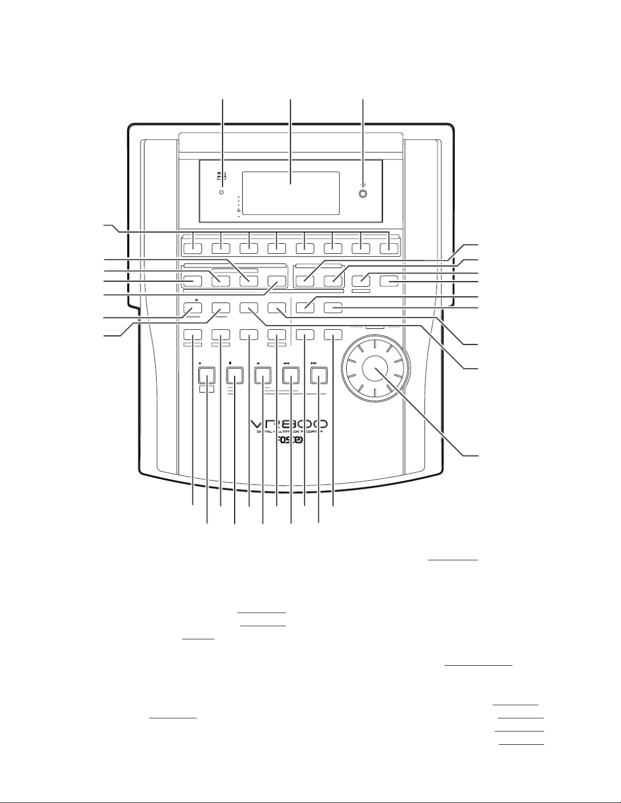
2. CONTROLS, INDICATORS AND CONNECTORS
< Top Panel Section >
1
30
29
28
27
26
25
23 4
OPTICAL
ACCESS
OL
0
6
12
24
5678
STORE
PGM SEL
VARI PITCH SCRUBLOCATEAUTO PLAY
SHIFT P.EDIT
RECORD
AUTO
PUNCH
AUTO RTN
AUTO PUNCH
STOP
1234
PREVIEW
EDITHOLD/
UNDO / REDO
AUTO RTN
PLAY REW F FWD
CLIPBOARD PLAY
LOCATE ABS 0
LOCATE REC END
RECORD TRACK
4321 5
ENDOUTINSTART
LOC MEM
DISP SEL
TIME BASE SEL
A SYNC
678
CLIPBOARD
SETUP
EXIT
/ NO
OUTIN
EJECT
JOG
SHUTTLE
EXECUTE
/ YES
5
6
7
8
9
10
11
12
1. Record track select keys [ RECORD TRACK (1 - 8) ]
2. Access LED [ ACCESS ]
3. LCD
4. Contrast adjustment knob
5. Clipboard In key [ CLIPBOARD IN / PREVIEW ]
6. Clipboard Out key [ CLIPBOARD OUT / PREVIEW ]
7. Exit/No key [ EXIT/NO / EJECT ]
8. Execute/Yes key [ EXECUTE / YES ]
9. Display indication select key [ DISP SEL ]
10. Setup key [ SETUP ]
11. Undo/Redo key [ UNDO / REDO ]
12. Edit key [ EDIT ]
13. JOG dial [ JOG / SHUTTLE ]
14. Scrub key [ SCRUB ]
15. Time Base select key [ TIME BASE SEL ]
13
141516171819
2021222324
16. Locate key [ LOCATE / LOC MEM ]
17. Auto Return/Auto Play mode on/off key
18. Vari Pitch key [ VARI PITCH / P.EDIT ]
19. Shift key [ SHIFT ]
20. Fast forward button [ F FWD ]
21. Rewind button [ REWIND ]
22. Play button [ PLAY ]
23. Stop button [ STOP ]
24. Record button [ RECORD / AUTO PUNCH ]
25. Store key [ STORE ]
26. Hold/> key [ HOLD/> ]
27. Auto Return End key [ AUTO R TN END / PREVIEW ]
28. Auto Return Start key [AUTO RTN ST ART / PREVIEW]
29. Auto Punch In key [ AUTO PUNCH IN / PREVIEW ]
30. Auto Punch Out key [AUTO PUNCH OUT / PREVIEW]
6
VR800 / VR800Z
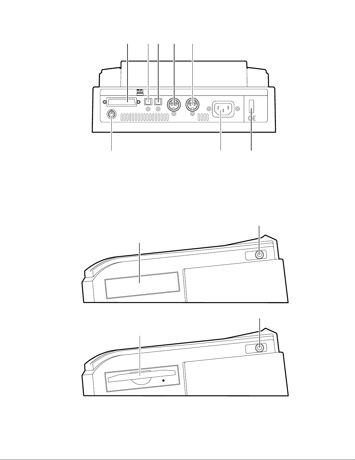
< Rear Panel Section >
31 32 33 34 35
DATA
SCSIWORD OUT
OPTICAL
INOUT
36 37 38
31. SCSI connector [SCSI] (Connector: D-SUB 25-pin)
32. Data output jack [DA T A OUT] (Connector: OPTICAL)
33. Data input jack [DATA IN] (Connector: OPTICAL)
34. MIDI OUT jack [MIDI OUT] (Connector: DIN 5-pin)
MIDI
POWERAC INOUT IN
35. MIDI IN jack [MIDI IN] (Connector: DIN 5-pin)
36. Word Out jack [WORD OUT] (Connector: BNC)
37. AC IN connector
38. Power switch [POWER]
< Side Panel Section - VR800 >
39
< Side Panel Section - VR800Z >
39
PUNCH
IN/OUT
PUNCH
IN/OUT
40
40
39. Blannk Panel (VR800)
Zip Drive (VR800Z)
40. Punch in/out jack [PUNCH IN/OUT]
(Connector: phone)
7
VR800 / VR800Z
3. SOFTWARE UPDATE
The VR800 software can be updated through the SCSI port. This means that unscrewing and opening up the VR800 panel is not
necessary to change the EPROMs. Please refer to the following explanation for correct software updating procedures.
3-1. Method of Sending Software from Fostex Japan
There are two ways of sending the VR800 updated software.
1. Updated software in a removable medium (e.g. floppy disk, zip disk, etc.) to be sent via airmail
2. Updated software as an attachment file to be sent via E-mail
3-2. Required Tools
The following tools/equipment are required to update the VR800 software.
1. IBM PC/AT compatible computer with SCSI board
2. Removable type SCSI drive
3. Cable between the removable type SCSI drive and the SCSI board
4. Cable between the removable type SCSI drive and the VR800 (D-SUB 25-pin)
3-3. Software Updating Procedures
Presuming that the updated software is correctly sent and is copied into your computer.
1. Connect the removable type SCSI drive to the IBM PC/AT compatible computer SCSI port.
2. Insert the diskette to the removable type SCSI drive and format it by the computer on which Windows 95/98 is running.
3. Copy the updated software file to the removable type SCSI drive (diskette).
4. Set the removable type SCSI drive ID to 0 ~ 5 and connect to the VR800 SCSI port.
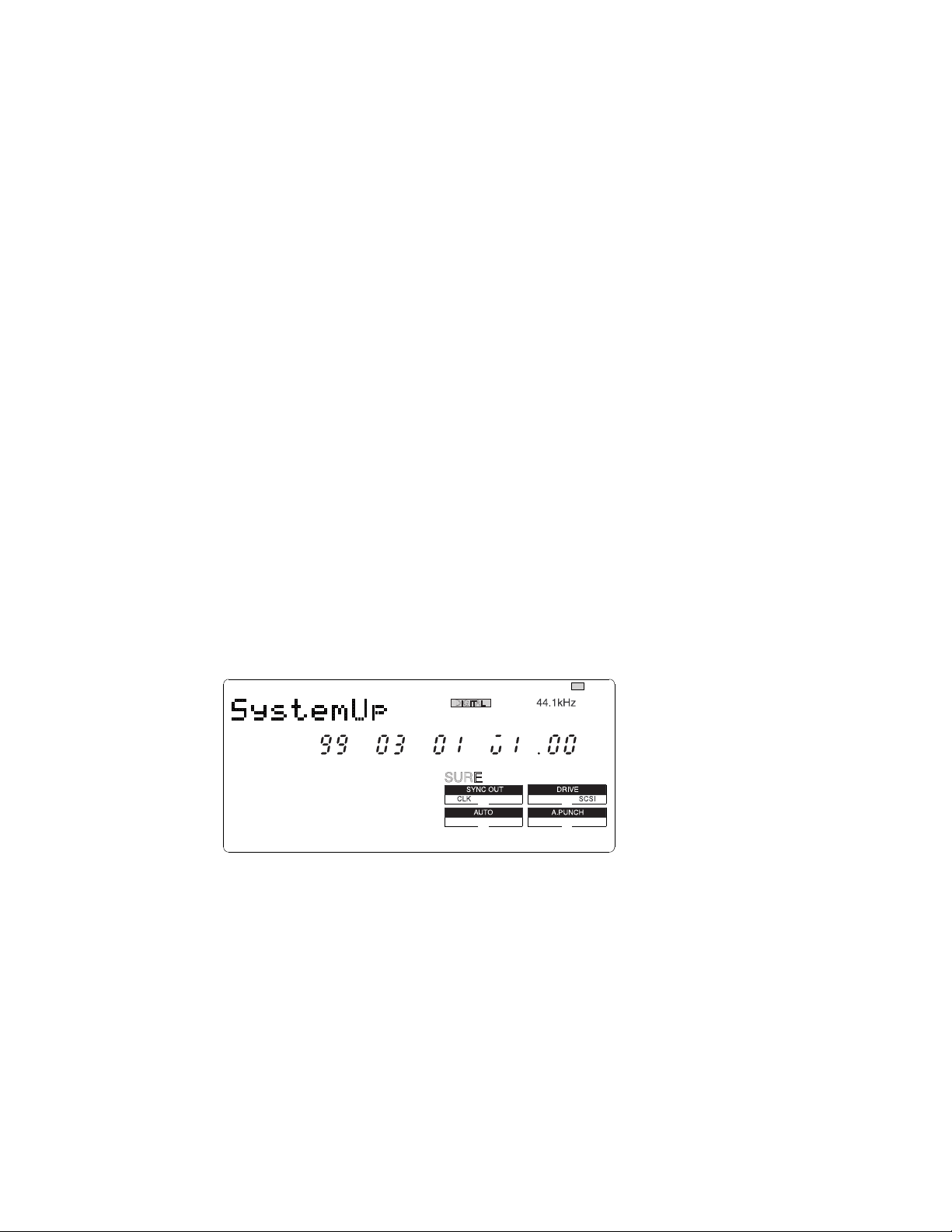
5. Turn on the power of removable drive and then VR800. The VR800 LCD display shows “No Disk”.
6. Insert the diskette with updated software file. The VR800 LCD display shows “No Disk”, “Initial..”, “name of drive
(e.g. ZIP 100)” and “updated software file name” in order and comes to a standstill at the display below. Memorize the
displayed ROM version and date before updating the software.
: blinking
?
7. Pressing the [EXECUTE/YES] key would start updating the software. The display shows “Loading!”, “Writing!” and
“Initial..” in order and automatically returns to the above condition again. Check the displayed ROM version and date
if the software is correctly updated by the optional mode “4-2. Flash ROM & CPU Version” (page 10).
8. Eject the diskette with updated software file by the press of [STOP] button or [EXIT/NO] key and insert the diskette
formatted by the VR800.
CAUTION:
1. The diskette in which the updated software file is copied must be formatted by IBM PC/AT computer, not by Macintosh.
2. If something wrong happens while updating the software (e.g. A blackout occurred while updating the software.), the
VR800 might not be able to boot up the system software inside the Flash ROM. In such a case, please refer to the
section “4-8. Flash ROM” (page 17).
3. The SCSI ID to be connected to the VR800 must be selected to 0 ~ 5. The SCSI ID “6” is used for backing up purpose
exclusively. The SCSI ID “7” cannot be used by technical reasons.
8
VR800 / VR800Z
Sign.Set? TempoSet? TitleEdit? Preroll? SyncOut?
N/A
N/A
N/A
N/A
N/A
N/A
N/A
BkFormat?
Format?
FrameRate?
MtcOffset?
OfsetMode?
SlaveMode?
SelfCheck?
OfsetDisp?
SlaveType?
RecProtect?
Format?
Del_PGM? Click_ ?
Version? DA_Test? Disp.Test?
Save_PGM? Load_PGM? NOsEvent?
Digi.out?
Digi.In?
DeviceID? Resolu?
Test_1? Freeblock?
FlashROM? Init.Disk?
C.W.
C.W.
C.W.
C.W.
C.W. C.W.
C.W.
C.W.
: SETUP Mode menu
: Service Mode menu
N/A : Not Available
VR800 LCD Display Section
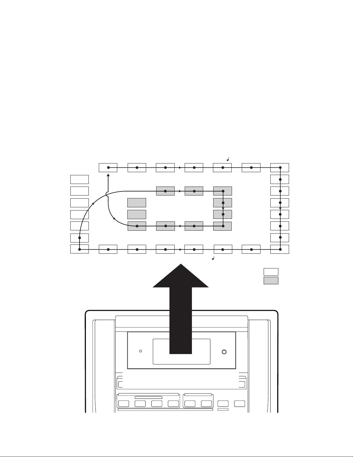
4. SERVICE MODE
There are various optional modes available in the VR800 Service Mode. Please utilize them when servicing the unit.
4-1. Putting VR800 into Service Mode
The way of putting the VR800 into Service Mode is as follow.
1. Connect a SCSI device, insert the diskette formatted by the VR800 and turn the power of SCSI device on.
2. After confirming that the access LED on the SCSI device is lit and then goes out, turn on the power of VR800.
3. While holding down the [STOP] button and [SHIFT] key, press the [SETUP] key.
As shown below, by rotating the jog dial C.W. or C.C.W., various optional modes will be displayed in addition
to the general SETUP menus. In order to select a certain optional mode, press the [EXECUTE/YES] key while
its menu is displayed.
9

VR800 / VR800Z
4-2. Flash ROM & CPU version
: blinking
: blinking
: blinking
This mode is used to check the Flash ROM and CPU versions
currently installed in the unit.
In order to check the version number, press the [EXECUTE/
YES] key while “?” is blinking as shown in the left.
The example on the left indicates that the Flash ROM version
is V1.01 and its programming date is April 13, 1999.
In this condition, by turning the jog dial C.W. or C.C. W.,
the CPU version can be checked.
The example on the left indicates that the CPU version is
V2.00 and its programming date is August 4, 1998.
10
4-3. DA Test
: blinking
Since there are no A to D and D to A converters used on the
VR800. this service mode does not function.
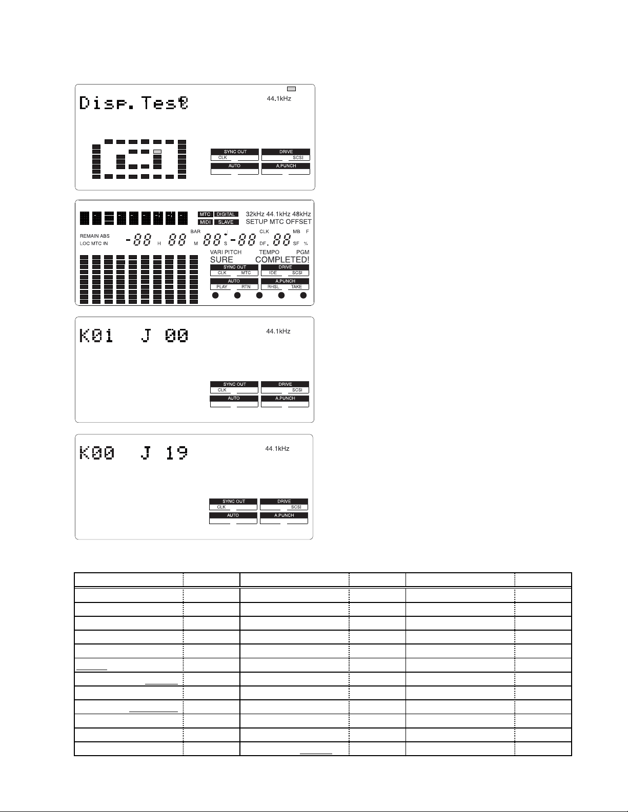
4-4. Display/Button Test
: blinking
This mode tests if all the segments on the LCD display, LEDs
and buttons (switches) on the VR800 top panel are correctly
working or not.
To execute this test, press the [EXECUTE/YES] key while
“?” is blinking.
If the VR800 is in a normal condition, all the segments on
the LCD display will be lit solid and all the LEDs on the top
panel will start blinking.
VR800 / VR800Z
?
If the VR800 is not in a normal condition, faulty segments
on the LCD display and/or LEDs on the top panel will remain
unlit.
In this condition, if the [EXECUTE/YES] key is pressed one
more time, the Button Test can be executed.
The Button Test checks if each key/button and jog dial are
working properly or not. The display on the left indicates
that the [RECORD] button is pressed and held down. (“K”
stands for the Key and “J” the Jog dial.)
The display on the left indicates the condition when the jog
dial is turned C.W.
The table below shows the relationship between the key/
button/jog dial and the corresponding numbers appear on the
LCD display.
In order to quit the Button Test, turn the jog dial C.W. or C.C.W.
further after “J_20” or “J-19” is displayed respectively.
Key/Button/Jog Dial No. Key/Button/Jog Dial No. Key/Button/Jog Dial No.
RECORD K0 1 STORE K1 3 EXECUTE / YES K25
STOP K02 EDIT K14 RECORD TRACK 1 K26
PLAY K03 UNDO / REDO K15 RECORD TRACK 2 K27
REWIND K04 DISP SEL K16 RECORD TRACK 3 K28
F F WD K05 SETUP K17 RECORD TRACK 4 K29
SHIFT K06 AUTO RTN START K18 RECORD TRACK 5 K30
VARI PITCH / P.EDIT K07 AUTO PUNCH IN K19 RECORD TRACK 6 K31
AUTO RTN / PLAY K08 AUTO PUNCH OUT K20 RECORD TRACK 7 K32
LOCATE /
LOC MEM K09 AUTO RTN END K21 RECORD TRACK 8 K33
TIME BASE SEL K 1 0 CLIPBOARD IN K22
SCRUB K11 CLIPBOARD OUT K23 JOG DIAL (C.W.) J 00 ~ 20
HOLD K12 EXIT / NO /
EJECT K24 JOG DIAL (C.C.W.) J -00 ~ -19
11
VR800 / VR800Z
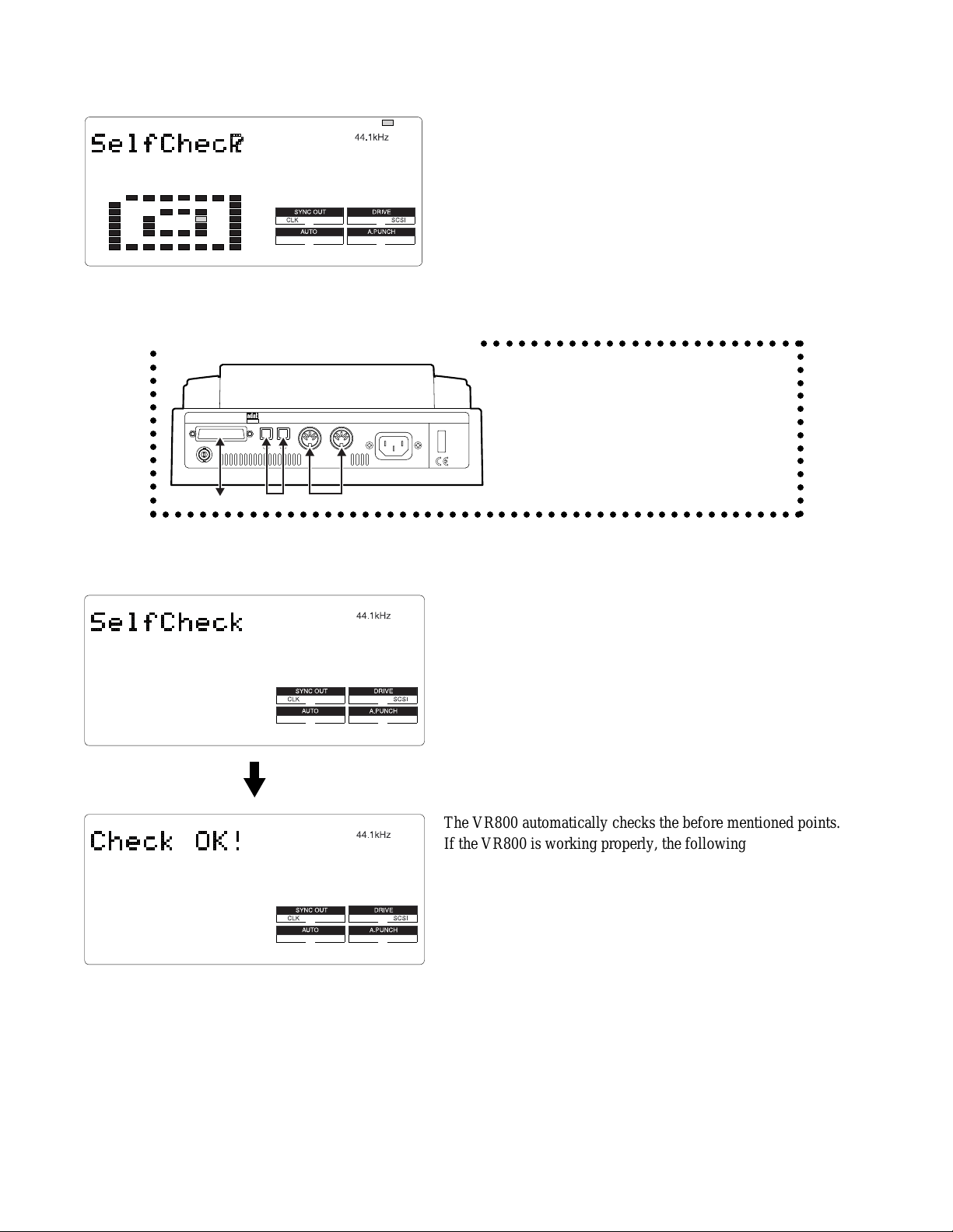
4-5. Self Check
: blinking
This mode automatically tests the following points in order.
• SCSI port
• ATA (E-IDE) bus
• MIDI in/out circuit
• S/P DIF digital signal (44.1kHz)
• adat digital signal (44.1kHz)
• Vari-pitch circuit
<Cable Connection in “ Self Check ” Mode>
○○○○○○○○○○○○○
SCSIWORD OUT
DATA
OPTICAL
MIDI
INOUT
POWERAC INOUT IN
○○○○○○○○○○○○○○○○○○○○○○○○○○
CAUTION :
In order not to form a MIDI signal loop,
connect the MIDI cable after putting the
VR800 into the Service Mode.
○○○○○○○○○○○○○○○○○○○○○○○○○○○○○○○○○○○○○○○○○○○○○○○○○○○○○
MIDI cableOptical cableExternal SCSI Device
To start the Self Check mode, press the [EXECUTE/YES] key
when “?” is blinking.
○○○○○○○○○○○○○○
12
The VR800 automatically checks the before mentioned points.
If the VR800 is working properly, the following appears on the
display with REC LED blinking.
In order to go back to the normal display, press the [EXIT/NO]
key or [STOP] button.
Fs, DIGITAL IN, DIGITAL OUT and SLAVE MODE settings on the disk to be used when the Self Check test is executed
should be as follow.
• Fs : 44.1kHz
• DIGITAL IN : OFF (L: - R: -)
• DIGITAL OUT : ADAT
• SLAVE MODE : OFF
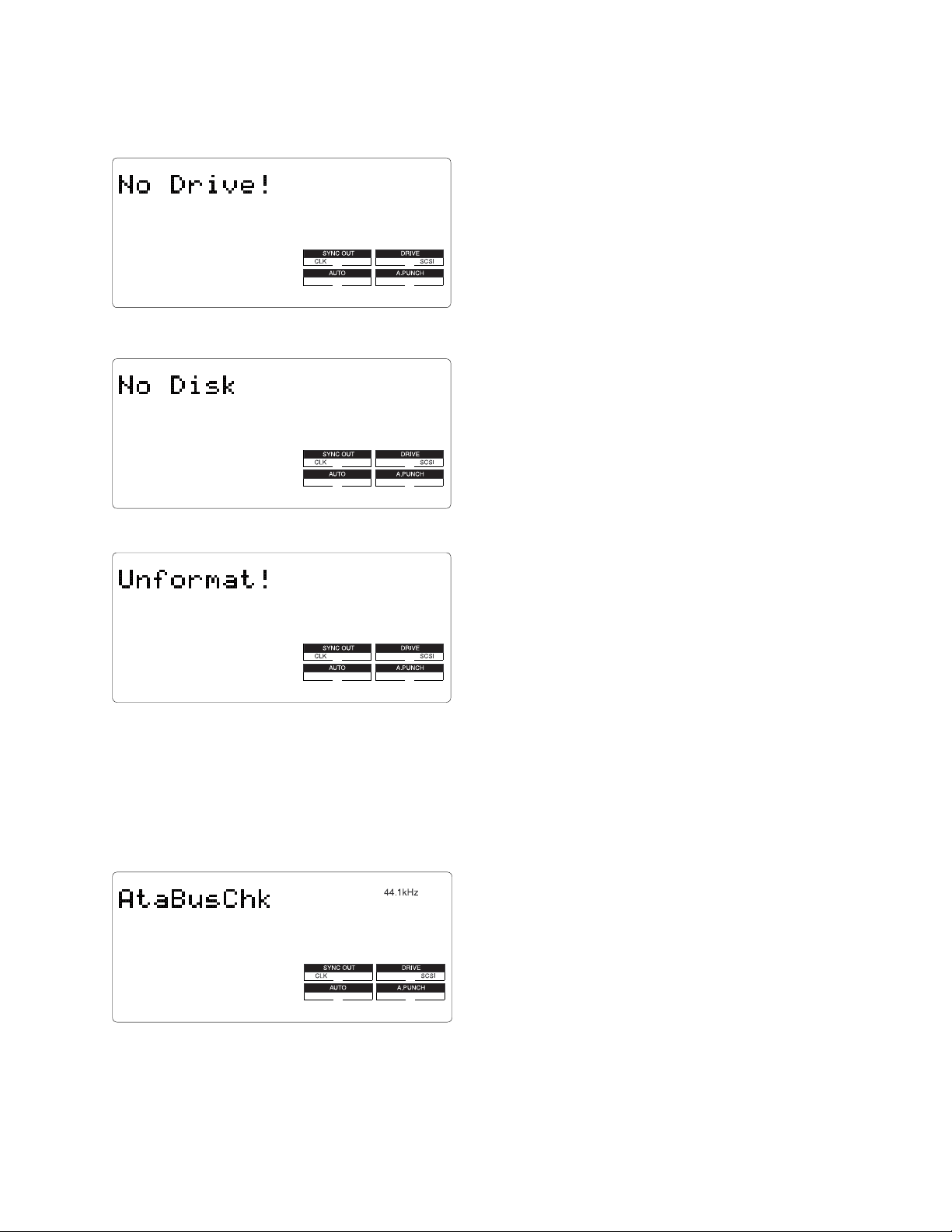
4-5-1. SCSI Port Check
VR800 / VR800Z
If the VR800 does not recognize a SCSI device connected to the
VR800 SCSI port, the prompt below will be displayed.
The following is considered to be the cause of problem.
• Bad cable connection, bad cable contact and / or the power
of SCSI device is being turned off.
• SCSI device ID is not set to 0 ~ 5.
• MAIN PCB is defective. (bad soldering of U7, U8, J6, etc.)
If a removable type SCSI drive is connected and in case a disk is
not inserted into the drive, the following prompt will be displayed.
In the case that the inserted disk is not FDMS-3 formatted, the
following prompt will be displayed.
Even if the before mentioned prompt is displayed, pressing the [EXECUTE/YES] key would reach the next test.
4-5-2. ATA (E-IDE) Bus Check
This test checks if data can be properly read out from the
preformatted internal drive.
If the data (SYSTEM ID) written by formatting the disk cannot
be read out correctly, the Self Check mode comes to a standstill
at “AtaBusChk (check)” test.
The following is considered to be the cause of problem.
• The internal drive is not installed in the VR800.
• Breaking, shortage and / or bad contact of flat cable J12.
• Bad soldering of gate array U5 on the MAIN PCB.
Even if the before mentioned prompt is displayed, pressing the [EXECUTE/YES] key would reach the next test.
13
VR800 / VR800Z
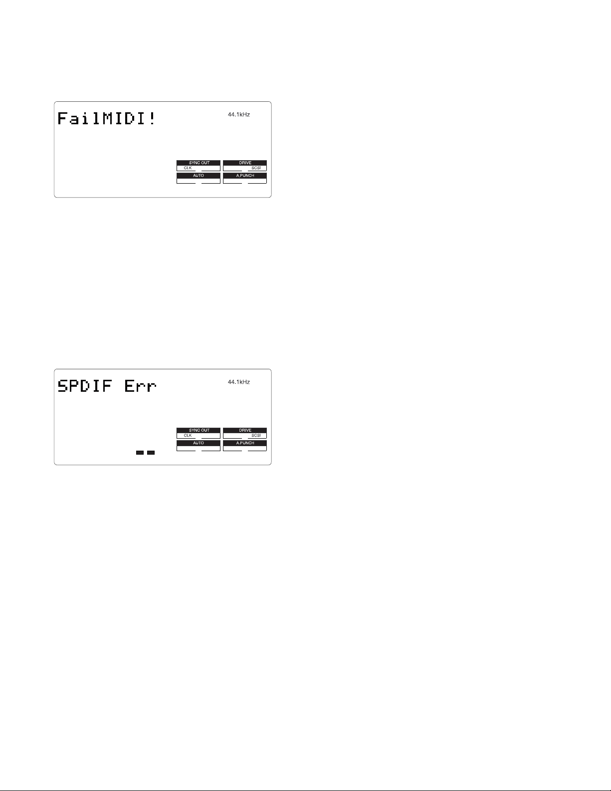
4-5-3. MIDI In/Out Check
Even if the before mentioned prompt is displayed, pressing the [EXECUTE/YES] key would reach the next test.
By connecting the MIDI IN and OUT ports, this test checks if
the reply against the ID inquiry is correctly received. If not, the
prompt below will be displayed.
The following is considered to be the cause of problem.
• Bad soldering of J2, U11 and surrounding circuit on the
MAIN PCB
4-5-4. S/P DIF In/Out Check
By connecting the DATA IN and OUT terminals, this tests checks
if the S/P DIF signal output by itself is correctly received. If the
PLL circuit is not in a “LOCKED” condition, the prompt below
will be displayed.
The following is considered to be the cause of problem.
• Defect on DIGITAL OUT
- No oscillation of resonator X1.
- Connector J4, gate array U5, U20 and / or surrounding
circuit are defective.
• Defect on DIGITAL IN
- Connector J5, gate array U5, U20 and / or surrounding
circuit are defective.
- PLL circuit (U10 and surrounding circuit) are defective.
• The SETUP “DIGITAL IN” is set other than “L: - R: -”.
Even if the before mentioned prompt is displayed, pressing the [EXECUTE/YES] key would reach the next test.
14
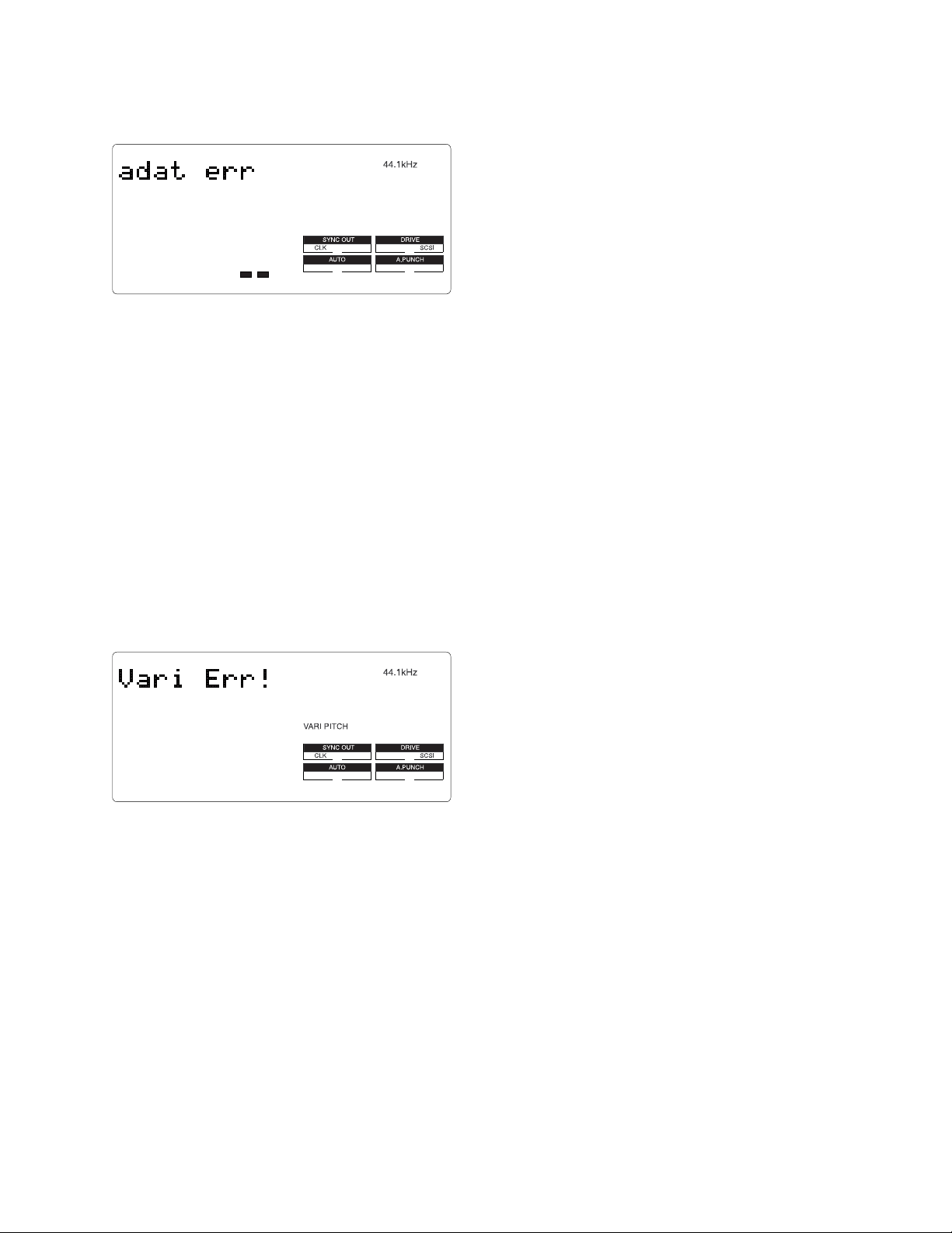
4-5-5. Adat In/Out Check
VR800 / VR800Z
By connecting the DATA IN and OUT terminals, this tests
checks if the ADAT digital signal output by itself is correctly
received. If the PLL circuit is not in a “LOCKED” condition,
the prompt below will be displayed.
The following is considered to be the cause of problem.
• Defect on DIGITAL OUT
- No oscillation of resonator X1.
- Connector J4, gate array U5, U20 and / or surrounding
circuit are defective.
• Defect on DIGITAL IN
- Connector J5, gate array U5, U20 and / or surrounding
circuit are defective.
- PLL circuit (U22, 23, 35, 36, 37, 38, 39 and / or
surrounding circuit) are defective.
• The SETUP “DIGITAL IN” is set other than “L: - R: -”.
Even if the before mentioned prompt is displayed, pressing the [EXECUTE/YES] key would reach the next test.
4-5-6. Vari-Pitch Circuit Check
Using the master clock generated through the VR800 vari-pitch
circuit on the MAIN PCB, the adat digital signal is output. This
test checks if the adat digital signal output by itself is correctly
received. If not, it means that the vari-pitch circuit does not work
correctly. As a result, the prompt below will be displayed.
The following is considered to be the cause of problem.
• Defects on the vari-pitch circuit (U3, U9), gate array (U5)
and / or surrounding circuit.
Even if the before mentioned prompt is displayed, pressing the [EXECUTE/YES] key would reach the next test.
15
 Loading...