

Fostex VM88 Service Manual

Service Manual
Model
8CH Digital Mixer with DSP Effects
FOSTEX CORPORATION 3-2-35 Musashino, Akishima, Tokyo, Japan 196-0021
FOSTEX CORPORATION OF AMERICA 15431 Blackburn Ave., Norwalk, CA 90650, U.S.A.
© PRINTED IN JAPAN MAR. 2000 8288789000
CAUTION
RISK OF ELECTRIC SHOCK
DO NOT OPEN
CAUTION: TO REDUCE THE RISK OF ELECTRIC SHOCK,
DO NOT REMOVE COVER (OR BACK).
NO USER-SERVICEABLE PARTS INSIDE.
REFER SERVICING TO QUALIFIED SERVICE PERSONNEL.
The lightening flash with arrowhead symbol,
within an equilateral triangle, is intended to
alert the user to the presence of uninsulated
“dangerous voltage” within the product's enclosure that may be of sufficient magnitude to
constitute a risk of electric shock to persons.
“WARNING”
“TO REDUCE THE RISK OF FIRE OR ELECTRIC SHOCK,
DO NOT EXPOSE THIS APPLIANCE TO RAIN OR MOISTURE.”
SAFETY INSTRUCTIONS
Read instructions - All the safety and operating instruc-
1.
tions should be read before the appliance is operated.
Retain instructions - The safety and operating instructions
2.
should be retained for future reference.
Heed warnings - All warnings on the appliance and in the
3.
operating instructions should be adhered to.
Follow instructions - All operating and use instructions
4.
should be followed.
Water and Moisture - The appliance should not be used
5.
near water - for example, near a bathtub, washbowl,
kitchen sink, laundry tub, in a wet basement, or near a
swimming pool, and the like.
Carts and Stands - The appliance should be used only
6.
with a cart or stand that is recommended by the manufacturer.
An appliance and cart combination should be moved with
care. Quick stops, excessive force, and uneven surfaces
may cause the appliance and cart combination to overturn.
Wall or Ceiling Mounting - The appliance should be
7.
mounted to a wall or ceiling only as recommended by the
manufacturer.
Ventilation - The appliance should be situated so that its
8.
location or position does not interfere with its proper ventilation. For example, the appliance should not be situated on a bed, sofa, rug, or similar surface that may block
the ventilation openings; or, placed in a built-in installation, such as a bookcase or cabinet that may impede the
flow of air through the ventilation openings.
CAUTION:
TO PREVENT ELECTRIC SHOCK, MATCH
WIDE BLADE OF PLUG TO WIDE SLOT,
FULLY INSERT.
ATTENTION:
POUR ÉVITER LES CHOCS ÉLECTRIQUES,
INTRODUIRE LA LAME LA PLUS LARGE DE
LA FICHE DANS LA BORNE CORRESPONDANTE DE LA PRISE ET POUSSER
JUSQU' AU FOND.
The exclamation point within an equilateral
triangle is intended to alert the user to the
presence of important operating and maintenance (servicing) instructions in the literature
accompanying the appliance.
Heat - The appliance should be situated away from heat
9.
sources such as radiators, heat registers, stoves, or other
appliances (including amplifiers) that produce heat.
Power Sources - The appliance should be connected to a
10.
power supply only of the type described in the operating
instructions or as marked on the appliance.
Grounding or Polarization - The precautions that should
11.
be taken so that the grounding or polarization means of
an appliance is not defeated.
Power Cord Protection - Power supply cords should be
12.
routed so that they are not likely to be walked on or
pinched by items placed upon or against them, paying
particular attention to cords at plugs, convenience receptacles, and the point where they exit from the appliance.
Cleaning - The appliance should be cleaned only as rec-
13.
ommended by the manufacturer.
Nonuse Periods - The power cord of the appliance should
14.
be unplugged from the outlet when left unused for a long
period of time.
Object and Liquid Entry - Care should be taken so that
15.
objects do not fall and liquids are not spilled into the enclosure through openings.
Damage requiring Service - The appliance should be ser-
16.
viced by qualified service personnel when:
The power supply cord or the plug has been damaged;
A.
or
Objects have fallen, or liquid has been spilled into the
B.
appliance; or
The appliance has been exposed to rain; or
C.
The appliance does not appear to operate normally or
D.
exhibits a marked changed in performance; or
The appliance has been dropped, or the enclosure
E.
damaged.
Servicing - The user should not attempt to service the ap-
17.
pliance beyond that described in the operating instructions. All other servicing should be referred to qualified
service personnel.
R
CH ON
A/D
ST OUT
D/A
10kHz
1kHz
100Hz
PAN
GAIN
MIC
L
(+4dBu)
To MON
ST OUT
To METER
D/A
ST MASTER
CH ON
EFF 1
HI
MID
LO
From DIGI IN
TRIM
(-10dBu~-50dBu)
-48V
12
AUX
12
EFF
R
ST
L
INSERT
PHANTOM (SETUP)
L
To DIGI OUT
ST MASTER
10kHz
To METER
1kHz
100Hz
To DIGI OUT
(-10dBV)
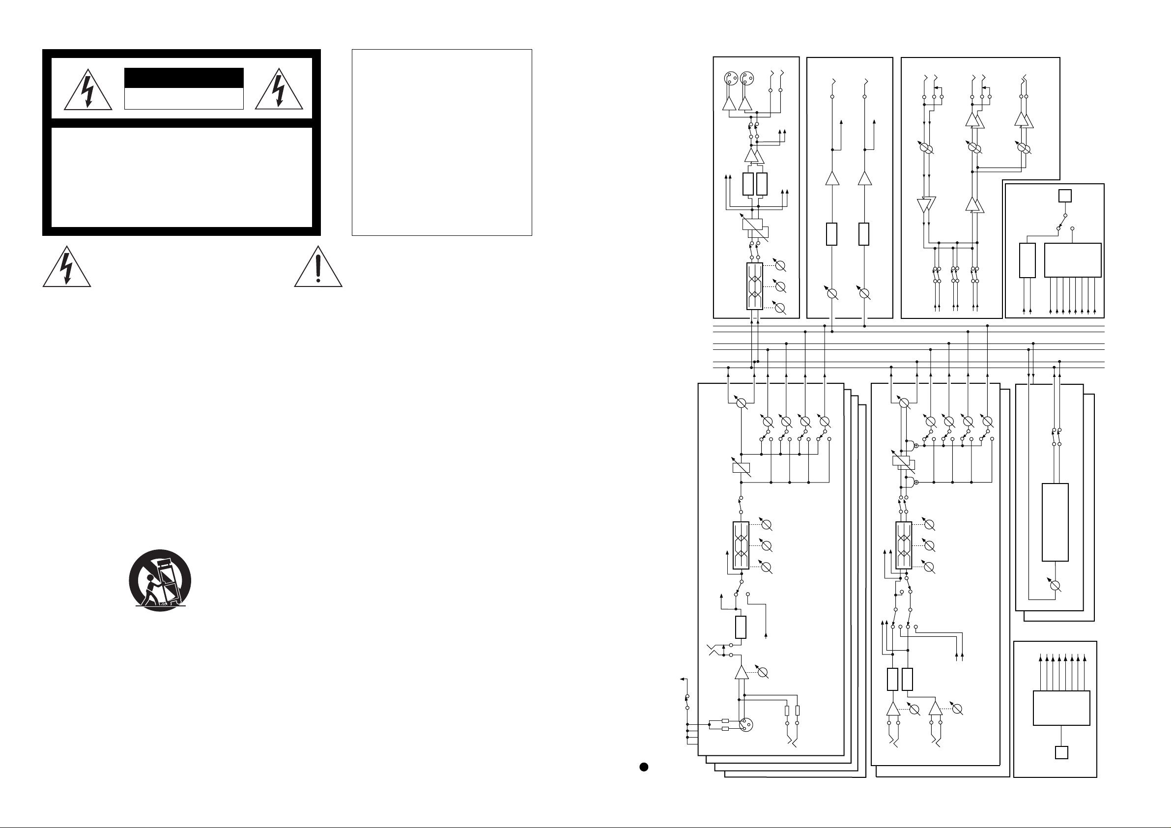
R
VM88 BLOCK DIAGRAM
ST OUT
(-10dBV)
HI
MID
LO
EFF 2
LINE
AUX 1 OUT
(-10dBV)
To MON
D/A
AUX 1
MASTER
AUX MASTER
AUX 1
AUX 2
PRE/POST
(+10dBu~-30dBu)
CH 1
CH 2
CH 3
D/A
CH 4
AUX 2 OUT
(-10dBV)
To MON
AUX 2
MASTER
To METER
To DIGI OUT
A/D
PAN
CH ON
10kHz
1kHz
100Hz
A/D
CH5 INPUT
(+4dBu~-40dBu)
L (M)
From AUX 1
MON
GAIN
MONO/STEREO
(SETUP)
DIGI IN
(SETUP)
TRIM
R
EFF 1
HI
MID
LO
SUB IN
(-10dBV)
AUX 1
From AUX 2
EFF 2
CH6 INPUT
(+4dBu~-40dBu)
L (M)
AUX 2
From ST
From DIGI IN
TRIM
AUX 1
R
ST
MON OUT
MON SEL
AUX 2
PRE/POST
CH5/6
(-10dBV)
PHONES
DIGI OUT
S/P DIF
ENCODE
From ST
EFF 1-2
DIGI IN
CH7/8
(100mW)
From CH1-A/D
From CH2-A/D
ASP
To CH4
To CH3
To CH2
To CH1
S/P DIF
or
ADAT
DIGI OUT
S/P DIF
ADAT
(SETUP)
ADAT
ENCODE
From CH8-A/D
From CH4-A/D
From CH3-A/D
From CH5-A/D
From CH7-A/D
From CH6-A/D
EFF MUTE
DIGITAL EFFECT
EFF 1
MASTER
To CH8
To CH7
To CH5
To CH6
DECODE
(SETUP)
DIGI IN
VM88
43
VM88 VM88
D+5
5
D+5
D+5
4
C33
100P
10
6
4
D+5
R984
10K
1
2 3
U923A
Q5Q
S
D2CK
DGND
U923B
Q9Q
S
D12CK
U920B 74VHC00
8
9
10
U920C
3
1
U920A
QA
QB
QC
ABCDENP
U919A
3 14
4 13
5 12
U928
6
3
8
11
2
QD
6 11
D+5
DTA114EK
74VHC00
74VHC74
R
74VHC74
R
C31
100P
74VHC00
157
1
13
DGND
RCO
ENTCKLOAD
291
10
U917B
DGND
R979
6
5
CLR
R985
10K
3
1
U929
DTC114EK
U924A
4
D+5
U924B
Q9Q
S
10
D12CK
74VHC161
100
74VHC86
4
3
S
2
Q5Q
D2CK
8
11
D+5
DGNDD+5
6
74VHC74
R
1
3
D+5
11
U920D
74VHC00
12
13
D+5
74VHC74
R
13
DGND
R982
100
U922B
Q9Q
S
10
D12CK
U922A
4
R980
S
8
11
Q5Q
D2CK
100
R983
R981
2.2K
74VHC74
R
13
6
74VHC74
R
3
D908
C32
100P
1SS 355
SPDIF//ADAT
SPDIF//ADAT
DGND
R969 NON
R968 22K
FCONT2
FCONT1
FCONT1
L7
22uH
0.01
C13
L98
D+5
FCONT2
C14
0.01
P GND
C27
220/10
820uH
1K
R971
R970 1K
/PLL1_CONT
/PLL2_CONT
/PLL2_CONT
/PLL1_CONT
10k
LOCK2
LOCK2
1
D+5
[DIF]
MCK
MCK
L4
EMI
U921B
Q9Q
S
10
D12CK
16151413121110
S2
S1
M2
M1
VDD
LOCK
REFPDVDDA
AMPI
AMPO
100
R972
PD2
PD1
R976 4.7 K
R975
VSSAXIXO
750
100
R973
PD1
PD2
1234567
L3
R978
R974
8
11
9
CKO
8
C15
100
330
R
EMI
VSS
0.01
C35
FS512
FS512
L6
EMI
4
7
9
12
1Y2Y3Y
74HC74
D+5
U925 TC9246F
C34
15P
U926A
M
R986 1
U927B
X902
PGND
C36
0.1
L5
74VHCU04
22.5792MHz
DGND
1A1B2A2B3A3B4A4BA/B
235
3 4
U927A
1 2
13
0.47
C16
0.01
EMI
C29
C28
6
111014
22P
74VHCU04
DGND DGND
22P
VCC
U927G
14
VCC
U926B
16
VCC
U924C
14
VCC
U923C
14
4Y
7
0.01
C25
8
0.01
C24
7
0.01
C23
7
13115
EXT//INT
EXT//INT
GND
74VHCU04
GND
74VHC157
GND
74VHC74
GND
74VHC74
74VHC157
G
DGND
TABLE OF CONTENTS
1. SPECIFICATIONS . . . . . . . . . . . . . . . . . . . . . . . . . . . . . . . . . . . . . . .
2. CONTROLS, INDICATORS AND CONNECTORS . . . . . . . . . . . .
3. SERVICE MODE . . . . . . . . . . . . . . . . . . . . . . . . . . . . . . . . . . . . .
4. EXPLODED VIEW, PCB ASSEMBLY AND PARTS LIST . . . . . .
5. CIRCUIT AND BLOCK DIAGRAMS . . . . . . . . . . . . . . . . . . . . . .
4
6
7
10
23
NOTES
0.01
U922C
14
U921C
14
VCC
C21
VCC
C22
GND
74VHC74
7
0.01
GND
74VHC74
7
Service mode, exploded view, PCB assembly, parts list and circuit diagrams are given in this manual
*
to assist the service technician in maintaining the Model VM88.
The following accessories are supplied with VM88 as the standard accessories.
*
Owner's manual : 8288458000 (for export & domestic model)
0.01
U920E
14
U919B
16
U917E
14
C20
VCC
C19
VCC
C18
VCC
C17
GND
7
0.01
GND
8
0.01
GND
7
0.01
74VHC00
74VHC161
74VHC86
DGND
Following is the packing material for the Model VM88.
*
Carton, inner, VM88 : 8228737000
Packing, side, L, VM88 : 8228465001
Packing, side, R, VM88 : 8228465002
CAUTION
!
Parts marked with this sign are safety critical components. They must always be replaced with identical
components. Refer to the Fostex Parts List and ensure exact replacement.
U917A
PLL, DIGITAL, MAIN, VM88
MCK
1
2
DATA_IN
DATA_IN
74VHC86
6
U921A
Q5Q
S
4
D+5
D2CK
3
4. MAIN_D, DSP1 2
5. MAIN_D, DSP3
6. MAIN_D, DSP SEL
U927F
74HC04
74VHC74
R
1
LRCK
D+5
LRCK
U927E
74HC04
D+5
74HC04
U927D
56 98 1110 1312
U927C
DGND
74HC04
2. MAIN_D, CPU
1. MAIN_D, ROOT
8. MAIN_D, PLL
3. MAIN_D, DSP_ROOT
7. MAIN_D, GA_DIF
D+5
42 3
VM88 VM88
1. SPECIFICATIONS
Specification Unit 0 dBV = 1 Vr.m.s., 0 dBu = 0.775 Vr.m.s.
Standard Input
INPUT 1 ~ 4
Connector XLR Cannon (MIC)
Ø 6 mm TRS phone jack (LINE)
Input level -50 dBu ~ -10 dBu (MIC)
-30 dBu ~ +10 dBu (LINE)
Input impedance 3 kΩ or more (MIC)
10 kΩ or more (LINE)
INPUT 5 - 8
Connector Ø 6 mm TRS phone jack
Input level -40 dBu ~ +4 dBu
Input impedance 10 kΩ or more
INSERT 1 - 4
Connector Ø 6 mm TRS phone jack
Input level -10 dBV
Input impedance 10 kΩ or more
MON IN L, R
Connector Ø 6 mm TRS phone jack
Input level -10 dBV
Input impedance 10 kΩ or more
DATA IN
Connector Square shape optical
Format
S/P DIF IN IEC consumer optical standard (IEC 958 Part 3)
ADAT IN Alesis Proprietary Multichannel Optical Digital Interface
Standard Output
STEREO OUT L, R
Connector XLR Cannon
Ø 6 mm TRS phone jack
Output level +4 dBu (XLR Cannon)
-10 dBV (Ø 6 mm TRS phone jack)
Load impedance 10 kΩ or more (XLR Cannon & Ø 6 mm TRS phone jack)
AUX SEND 1, 2
Connector Ø 6 mm TRS phone jack
Output level -10 dBV
Load impedance 10 kΩ or more
MON OUT L, R
Connector Ø 6 mm TRS phone jack
Output level -10 dBV
Load impedance 10 kΩ or more
PHONES OUT L, R
Connector Ø 6 mm TRS phone jack
Output level 50 mW or more
Load impedance 32 Ω
DATA OUT
Connector Square shape optical
Format
S/P DIF OUT IEC consumer optical standard (IEC 958 Part 3)
ADAT OUT Alesis Proprietary Multichannel Optical Digital Interface
EQ
HI 10 kHz ± 18 dB (shelving type)
MID 1 kHz ± 18 dB (peaking type)
LO 100 Hz ± 18 dB (shelving type)
Fader (VR) Position at Standard Input / Output
Input Fader 80 position
INPUT 1 ~ 4 (TRS) +10 dBu, 1 kHz
pll.sch
DATA_IN
/PLL2_CONT
LOCK2
FCONT2
LRCK
SPDIF//ADAT
PLL
LRCK
DATA_IN
SPDIF//ADAT
/PLL2_CONT
LOCK2
FCONT2
C9
0.01
U918
81
82
83
84
85
86
0.01
C6
87
88
89
90
91
92
93
94
95
96
97
98
99
100
FS256
FS256
R966
U903C
LRCK
100
5 6
/LRCK
D+5
74VHC14
/LRCK
DGND
C26
10/16
R41
100
8
U914C
74VHC00
9
10
C44
100P
47
R40
11
U913D
74VHC00
12
13
BCK
BCK
DIGITAL I/F, DIGITAL, MAIN, VM88
FS512
EXT//INT
DATA_OUT
FS512
EXT//INT
FS512
EXT//INT
PD1
FCONT1
MCK
/PLL1_CONT
PD2
//
PD1
FCONT1
MCK
/PLL1_CONT
PD2
8079787776757473727170696867666564636261605958575655545352
PD2
MCK2
FCONT2
LOCK2
PLL2_CONT
CK_SEL2
CK_SEL1
CK_SEL0
PCMBW1
PCMBW0
FS256I
VSS
VDD
BCKI
LRCKI
LRCKO
BCKO
FS256O
W_IN1
W_IN2
W_OUT
TDO_FS1O
TDO_FS0O
TDO_EMPO
123456789
DGND
PD1
VSS
PIPOTEST1
SPDIF//ADAT
MCK1
LOCK1
FCONT1
PLL1_CONT
TEST2
VDDA4A3A2A1A0WRRDVSSCSRESETD0D1D2D3D4D5D6D7
A4A3A2A1A0
A[0...4]
A[0...4]
CPU>
DATA_OUT
R964
100
C7
0.01
DO2
DO1
DO_SEL1
ADAT_MD
/WR_DIF
DO_EMPI
/RD_DIF
/RD_DIF
/WR_DIF
CPU>
CPU>
DO_SEL0
101112131415161718192021222324252627282930
R965
VSS
VDD
DO_FS0I
DO_FS1I
D0D1D2D3D4D5D6
/RST_DIF
/CS_DIF
/RST_DIF
/CS_DIF
CPU>
CPU>
SPDIFOUT
SPDIFOUT
100
SOUT_DI
SOUT2_78
SOUT2_56
DGND
C30
100P
SOUT2_34
SOUT_78
SOUT_56
SOUT_78
SOUT_56
246
R967
VSS
SOUT2_12
SOUT1_78
SOUT1_56
CTL_PIN
D7
SOUT_34
SOUT_12
SOUT_34
SOUT_12
87
100 X 4
531
DI_EMPO
SOUT1_34
SOUT1_12
VDD
VSS
EN_IF
C12
D[0...7]
CPU> D[0...7]
51
DI_FS0O
SINA_MD
0.01
C10
DI_FS1O
DI_SEL
DI2
DI1
SIN_DIF
SINB_78
SINB_56
SINB_34
SINB_12
VDD
VSS
SINA_78
SINA_56
SINA_34
SINA_12
TDI_EMPI
TDI_FS0I
TDI_FS1I
SOUT2_MD
SOUT1_MD
DATA_IN
4. MAIN_D, DSP1 2
5. MAIN_D, DSP3
6. MAIN_D, DSP SEL
8. MAIN_D, PLL
2. MAIN_D, CPU
3. MAIN_D, DSP_ROOT
7. MAIN_D, GA_DIF
DATA_IN
0.01
GA_DIF
50
49
48
47
46
45
44
43
42
41
40
39
38
37
36
35
34
33
32
31
0.01
C11
C8
0.01
1. MAIN_D, ROOT
ADO4
ADO3
ADO2
ADOA
ADO4
ADO3
ADO2
ADO1
ADO[1...4]
ADO[1...4]
STOUT
STOUT
4 41
VM88 VM88
Fader (VR) Position at Standard Input / Output (continued)
INPUT 5 ~ 8 (TRS) +4 dBu, 1 kHz
D+5
PAN L (R)
Master Fader Adjust so that ST OUT level is at -10 dBV. ( ST OUT SW: ON)
91011
WRDY_DSP[1...3]
DRDY_DSP[1...3]
INPUT 1 ~ 4 (TRS) +10 dBu, 1 kHz
INPUT 5 ~ 8 (TRS) +4 dBu, 1 kHz
/RST_DSP[1...3]
/WRQ_DSP[1...3]
U916C
74VHC10
8
WRDY_DSP[1...3]
DRDY_DSP[1...3]
PAN L (R)
MON OUT VR Adjust so that MON OUT level is at -10 dBV. (ST OUT SW: ON,
MON SEL SW: ST)
INPUT 1 ~ 4 (TRS) +10 dBu, 1 kHz
INPUT 5 ~ 8 (TRS) +4 dBu, 1 kHz
/RST_DSP[1...3]
/WRQ_DSP[1...3]
PAN L (R)
MON IN VR Adjust so that MON OUT level is at -10 dBV. (ST OUT: ON,
MON SEL: ST)
/RST_DSP1
/RST_DSP2
SO_DSP[1...3]
SCK_DSP[1...3]
/WRQ_DSP1
11
U914D
/WRQ_DSP
12
13
/WRQ_DSP2
74VHC00
U914A
1
74VHC00
234
/WRQ_DSP3
6
U914B
5
74VHC00
U915C
9
/RST_DSP3
8
U915D
74VHC00
10
12
3
11
2
/RST_DSP
74VHC00
SEL3
SEL2
SEL1
13
74VHC00
U915A
1
D+5
WRDY_DSP1
345
WRDY
U916B
4
U915B
6
WRDY_DSP2
WRDY_DSP3
74VHC10
6
5
74VHC00
U917C
DRDY
DRDY_DSP1
DRDY_DSP2
9
10
74VHC86
8
12
U917D
DRDY_DSP3
13
11
74VHC86
INPUT 1 ~ 4 (TRS) +10 dBu, 1 kHz
INPUT 5 ~ 8 (TRS) +4 dBu, 1 kHz
PAN L (R)
Output Level
INPUT 1 ~ 8
INPUT 1 ~ 8
→→
→ STEREO OUT -10 dBV ± 2 dB
→→
→→
→ MONITOR OUT -10 dBV ± 2 dB
→→
Frequency Response
INPUT 1 ~ 8
→→
→ STEREO OUT / MONITOR OUT / AUX SEND
→→
INPUT 1 ~ 4 20 Hz ~ 20 kHz +1, -3 dB (LINE level)
INPUT 1 ~ 4 20 Hz ~ 20 kHz +1, -3 dB (MIC level)
INPUT 5 ~ 8 20 Hz ~ 20 kHz +1, -3 dB (LINE level)
→→
→ PHONES OUT
→→
SO_DSP[1...3]
SCK_DSP[1...3]
R962 100
R963 100
INPUT 1 ~ 8
INPUT 1 ~ 4 30 Hz ~ 20 kHz +1, -3 dB (LINE level)
INPUT 1 ~ 4 30 Hz ~ 20 kHz +1, -3 dB (MIC level)
INPUT 5 ~ 8 30 Hz ~ 20 kHz +1, -3 dB (LINE level)
T.H.D. (w/ distortion filter NF3346A, 3347 or equivalent)
WRDY_DSP
DRDY_DSP
INPUT 1 ~ 8
→→
→ STEREO OUT / MONITOR OUT / AUX SEND
→→
INPUT 1 ~ 4 (0 dBu, XLR) 0.03 % or less
SO_DSP1
SI_DSP
SI_DSP
SCK_DSP1
11
U912D
12
13
U912C
74VHC00
9
SCK_DSP2
8
74VHC00
10
U912B
4
SCK_DSP3
6
74VHC00
5
3
U912A
1
D+5
74VHC00
2
SCK_DSP
SCK_DSP
SO
1
U913A
SEL3
SEL2
SEL1
SELECTOR
CPU (SBIO P18)> SI_DSP
DSP SELECT, DIGITAL, MAIN, VM88
CPU (SBTO P20)>
SO_DSP2
2
4
U913B
74VHC00
3
1213
U916A
R961
SO_DSP3
5
9
U913C
74VHC00
6
74VHC10
12
100
SO_DSP
SO_DSP
CPU (SBIO P19)<
4. MAIN_D, DSP1 2
5. MAIN_D, DSP3
2. MAIN_D, CPU
3. MAIN_D, DSP_ROOT
1. MAIN_D, ROOT
DGND
DRDY_DSP
6. MAIN_D, DSP SEL
8. MAIN_D, PLL
7. MAIN_D, GA_DIF
D+5
WRDY_DSP
VCC
U916D
14
C2
VCC
U915E
14
C5
VCC
U914E
14
C1
VCC
U913E
14
C3
VCC
U912E
14
C4
0.01
7
7
7
7
7
GND
GND
GND
0.01
GND
0.01
GND
74VHC00
0.01
74VHC00
0.01
74VHC00
74VHC00
74VHC00
SEL1
SEL2
74VHC00
SEL3
WRQ_DSP
SEL[1...3]
SEL[1...3]
WRQ_DSP
RST_DSP
RST_DSP
10
8
INPUT 1 ~ 4 (-40 dBu, XLR) 0.05 % or less
INPUT 1 ~ 4 (+20 dBu, TRS) 0.03 % or less
INPUT 1 ~ 4 (-20 dBu, TRS) 0.05 % or less
INPUT 5 ~ 8 (+14 dBu, TRS) 0.03 % or less
INPUT 5 ~ 8 (-30 dBu, TRS) 0.05 % or less
S/N (w/ distortion filter NF3346A, 3347 or equivalent)
INPUT 1 ~ 8
→→
→ STEREO OUT / MONITOR OUT
→→
INPUT 1 ~ 8 (LINE level, XLR) 90 dB or more
INPUT 1 ~ 4 (MIC level, XLR) 78 dB or more
INPUT 5 ~ 8 (MIC level, TRS) 86 dB or more
INPUT 1 ~ 8
→→
→ AUX SEND
→→
INPUT 1 ~ 8 (LINE level, XLR) 90 dB or more
INPUT 1 ~ 4 (MIC level, XLR) 78 dB or more
INPUT 5 ~ 8 (MIC level, TRS) 86 dB or more
Mic Gain
INPUT 1 ~ 4 40 dB ± 3 dB
INPUT 5 ~ 8 44 dB ± 3 dB
Crosstalk 60 dB or more at 1 kHz (50 dB or more at PHONES OUT)
Click Noise
POWER ON / OFF -20 dB p-p or less
Other switching -30 dB p-p or less
Shock Noise -30 dBVp-p
Specifications and appearance are subject to change without notice for product improvement.
“Adat” and symbol are trademarks of Alesis Corporation.
OPTICAL
40 5
VM88 VM88
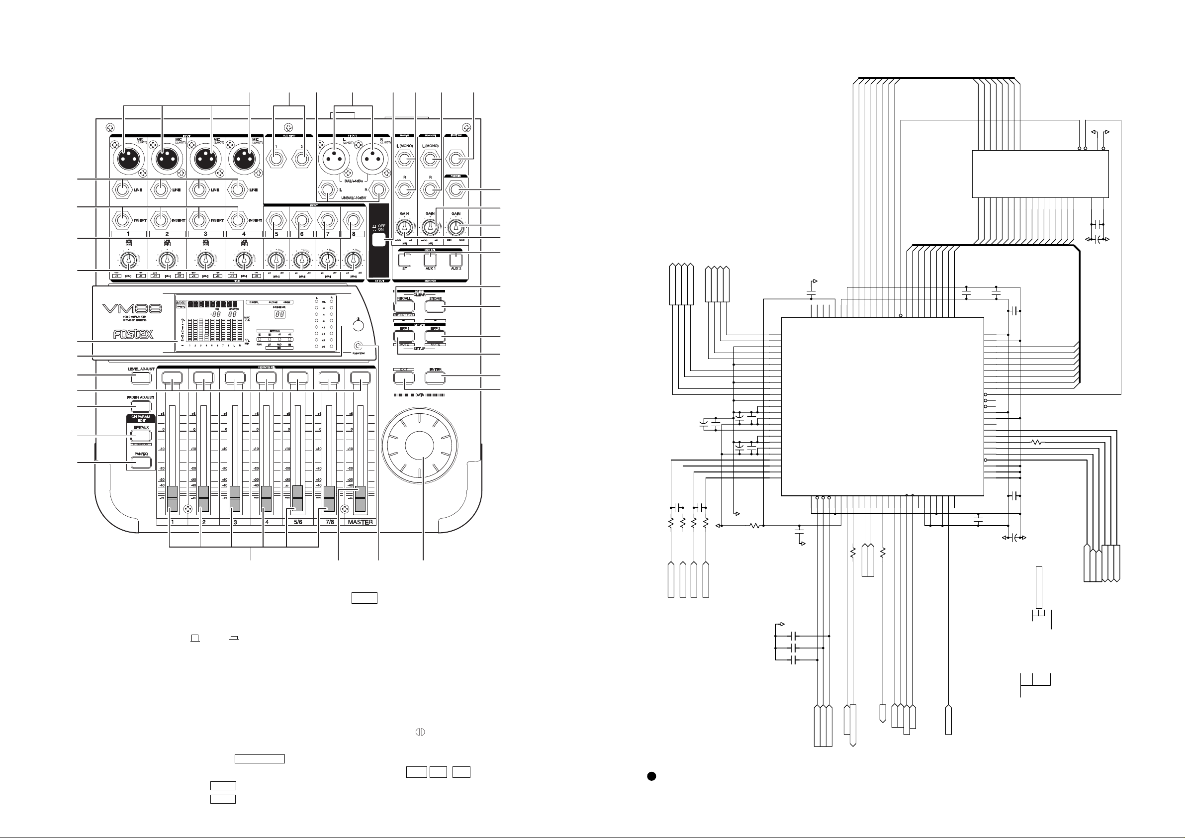
2. CONTROLS, INDICATORS AND CONNECTORS
< Top Panel Section >
1
3
2
45367
EFFD[0...7]
EFFD0
EFFD1
EFFD2
EFFD3
EFFD4
EFFD5
21222325262728
I/O0
I/O1
I/O2
I/O3
I/O4
I/O5
EFFD6
EFFD7
29
I/O6
I/O7
D+5
/WE
6
CE2
DGND
/CE1
32
5
/OE
1
32
31
30
29
28
27
26
25
24
23
22 21
1. Input connector [
2. AUX send jack [
3. Stereo out connector [
MIC (2: HOT) / LINE
AUX SEND 1, 2
ST OUT L (2: HOT),
R (2: HOT) BAL / +4dBu / L, R UNBAL / -10dBV]
4. Stereo out ON/OFF switch [
5. Monitor in jack [
6. Monitor out jack [
MON IN L (MONO), R
MON OUT L (MONO), R
7. Foot switch connecting jack [
8. Headphone jack [
PHONES
9. Monitor out adjusting knob [
10. Headphone volume [
11. Monitor input adjusting knob [
12. Monitor select switch [
13. Scene Recall key [
14. Scene Store key [
15. Effect 2 key [
16. Effect 1 key [
SCENE RECALL /
SCENE STORE
EFF EDIT EFF1 /
EFF EDIT EFF2 /
OFF / ON
FOOT SW
]
GAIN -
MIN / MAX
GAIN -
ST / AUX1 / AUX2
]
]
∞ / +6 [dB]]
]
∞ / +6 [dB]]
DIRECT RCL
]
]
MUTE
]
MUTE
]
]
EFFD7
EFFD6
EFFD5
EFFD4
EFFD3
EFFD2
EFFD1
EFFD0
IO4
IO3
SDIND2
SDOUTD2
100
STOUT
R958
ST_B
/OE
IO2
IO1
IO0
EFFECT
SDOUT1
SDOUT2
SDIN1
EFF_A
EFF_B
ST_B
EFF_A
EFFA16
/OE
A16
SDIN2
LRCK
/LRCK
EFF_B
/LRCK
EFFA14
EFFA15
A15
BITCLK
BCK
BCK
EFFA13
A14
A13
CLKO
EFFA12
A12
CTRL
DVDD
EFFA11
A11
DVSS
EFFA9
EFFA10
A9
A10
AK7716
OPCL
XTI
FS512
FS512
A0A1A2A3A4A5A6A7A8A9A10
U911
20191817161514
EFFA0
EFFA1
EFFA8
0.01
C976
A8
DVDD
DVSS
A7
A6
A5
A4
A3
A2
A1
A0
/WE
/RAS
/CAS
DVDD
DVSS
EEST
DRDY
RDY
SO
SI
SCLK
/RQ
JX
EESEL
SMODE
XTO
25
0.01
C982
EFFA2
EFFA3
C978
50
49
48
47
46
45
44
43
42
41
40
39
38
37
36
35
34
33
32
31
30
29
28
27
26
EFFA4
EFFA5
0.01
C980
AD+5
3
2311124117
13
EFFA6
EFFA7
EFFA8
EFFA9
C979
0.01
100
0.01
C981
10/16
DGND
2. MAIN_D, CPU
1. MAIN_D, ROOT
A11
A12
A13
A14
A15
EFFA10
EFFA11
EFFA12
EFFA13
EFFA14
EFFA15
EFFA7
EFFA6
EFFA5
EFFA4
EFFA3
EFFA2
EFFA1
EFFA0
R960
4. MAIN_D, DSP1 2
5. MAIN_D, DSP3
6. MAIN_D, DSP SEL
8. MAIN_D, PLL
3. MAIN_D, DSP_ROOT
7. MAIN_D, GA_DIF
VCC
A16
8
10
C995
EFFA16
D+5
C999
EFFA[0...16]
DRDY_DSP3
WRDY_DSP3
SI_DSP3
SCK_DSP3
/WRQ_DSP3
/WRQ_DSP3
SCK_DSP3
VSS
TC551001CFT-70L
24 30
0.01
DGND
16
10/
SI_DSP3
SI_DSP3
SO_DSP3
WRDY_DSP3
DRDY_DSP3
/WE
8
9
10
11
12
13
STOUT_L+
STOUT_L-
STOUT_R+
STOUT_R-
14
AUXSEND_BL+
AUXSEND_BL-
AUXSEND_BR+
AUXSEND_BR-
U910
STOUT_L+
STOUT_L-
STOUT_R+
15
16
17
18
AUXSEND_BL+
AUXSEND_BL-
AUXSEND_BR+
AUXSEND_BR-
C993
1500P
330
330
330
R954
R955
R953
AIN6+
AIN5-
AIN6-
C994
10/16
1500P
330
R956
AIN5+
C991
0.1
C992
A+5
STOUT_R-
C989
C987
10/16
10/16
AGND
76
77
78
79
80
81
82
83
84
85
86
87
88
0.1
C990
89
90
91
92
93
0.1
C988
94
95
96
97
98
99
100
10
R959
20 19
17. Enter key [
18. Exit key [
ENTER
EXIT
19. Data encoder [
20. Phantom LED [
]
21. Master fader [
22. Input fader [
]
23. PAN/EQ select key [
24. EFF/AUX select key [
25. Fader adjust key [
26. Channel On/Channel select key [
27. Level adjust key [
28. Contrast adjusting knob [
]
29. Display/status/meter section
]
30. TRIM knob
[
LINE +10/-30 [dBu] / MIC -10 / -50 [dBu]
31. Input jack 5 ~ 8 [
32. Insert jack 1 ~ 4 [
]
]
]
DATA
PHANTOM
MASTER
]
]
1, 2, 3, 4, 5/6, 7/8
PAN/EQ
EFF/SEL
FADER ADJUST
LEVEL ADJUST
]
INPUT 5, 6, 7, 8
INSERT 1, 2, 3, 4
]
]
]
]
CH ON/CH SEL
]
]
]
AIN6+
AIN5-
AIN6-
[ANA]
AIN5+
[ANA]
[ANA]
[ANA]
DGND
]
]
DSP3, DIGITAL, MAIN, VM88
AGND
C975
0.1
75747372717069686766656463626160595857565554535251
IO7
IO6
AOUTR2-
EECS
AOUTR2+
NC
AOUTL2-
AOUTL2+
NC
AOUTR1-
AOUTR1+
NC
AOUTL1-
AOUTL1+
NC
VRDAL
AVSS
AVDD
ARDAH
VCOM
VRADL
AVSS
AVDD
VRADH
AINR-
AINR+
AINL-
AINL+
TESTI1
123456789
0.1
C983
AGND
C998 NON
C997 47P
C996 47P
DVB
EEDI
EESK
EEDO
/INIT_RESET
/CODEC_RESET
/DSP_RESET
SMUTE
/INIT_RST
/CODEC_RST
/TST_DSP3
/INIT_RESET
/CODEC_RST
/RST_DSP3
IO5
DVSS
DVDD
DSP3
DVB
SDINA
SDOUTA
SDOUTD1
SDIND1
101112131415161718192021222324
AUX_B
ST_OUT
AUX_B
R957 100
SPDIFOUT
ADO3
SPDIFOUT
ADO3
6 39
VM88 VM88
OL
1
6
12
24
48
14678LR532
MAX
R
MIN
L
MID HILOPAN
A1 A2E2E1
SCENE NO.
OL
-3
-6
-9
-12
-18
-24
-36
RL
OPTICAL
CH
MASTER
44.1kHz
1 243
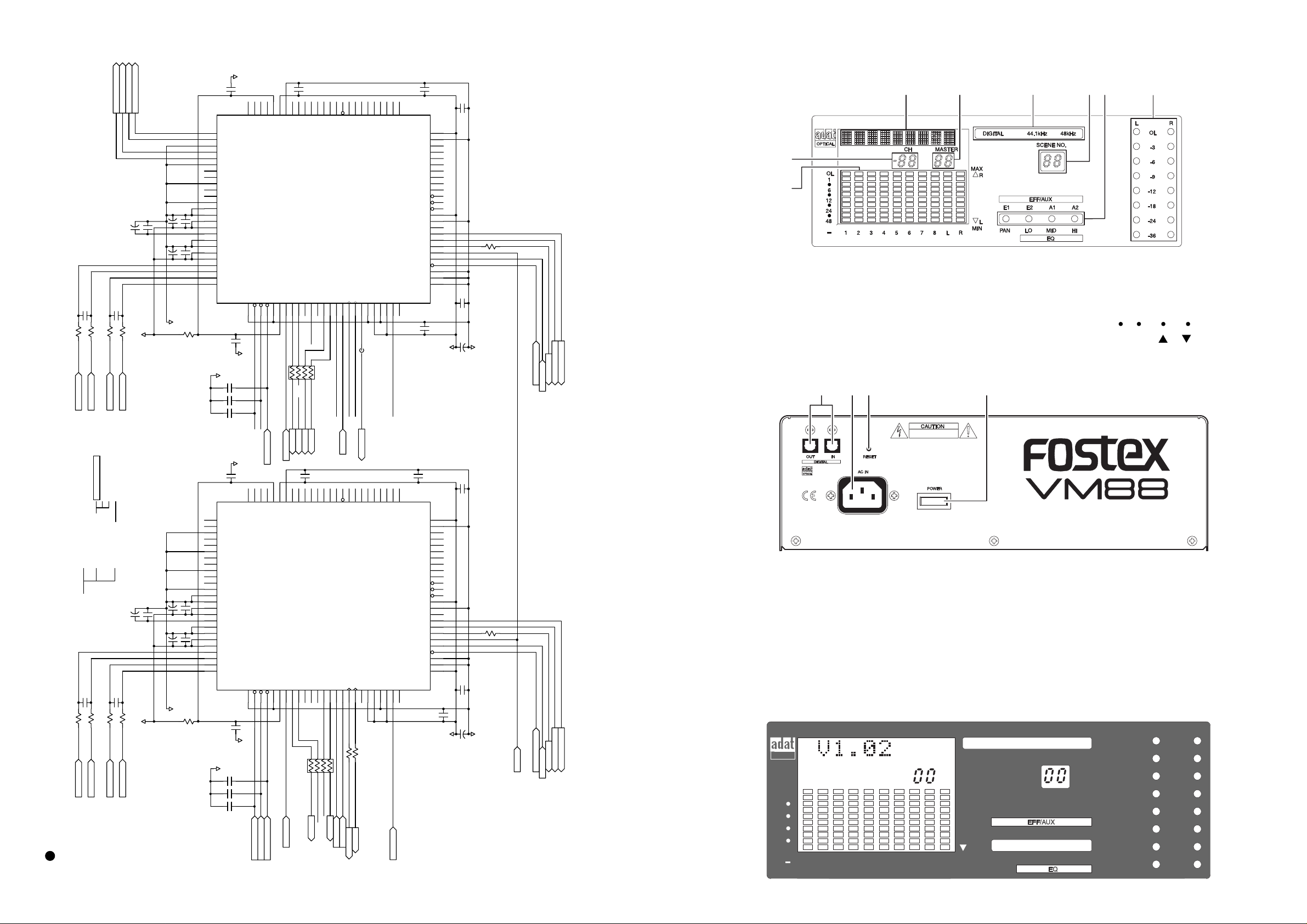
< Rear Panel Section >
A
B
H
D
C
E
G
F
< Display/status/meter Section >
330
R939
AIN4-
C967
AIN4-
[ANA]
1500P
330
R940
AIN4+
AIN4+
[ANA]
AUXSEND_AL+
AUXSEND_AL-
AUXSEND_AL+
AUXSEND_AL-
C968
1500P
330
330
R941
R942
AIN3-
AIN3+
AIN3-
AIN3+
[ANA]
[ANA]
AUXSEND_AR+
AUXSEND_AR-
10/16
C965
C966 0.1
A+5
AUXSEND_ARAUXSEND_AR+
0.1
C964
C963
10/16
0.1
C961
C962
10/16
AGND
DVB
DVSS
DVDD
EEDO
/DSP_RESET
SMUTE
DVB
SDINA
/RST_DSP2
SOUT_12
C951
0.01
IO7
IO6
IO5
IO4
IO3
IO2
IO1
IO0
/OE
A16
A15
A14
U909
DSP2
SDOUTA
SDOUTD1
SDIND1
SDIND2
SDOUTD2
SDOUT1
SDOUT2
SDIN1
SDIN2
LRCK
BITCLK
CLKO
101112131415161718192021222324
246
ADO2
AUX_B
AUX_A
87
531
STOUT
EFF_B
100X 4
R950
ST_A
ST_B
/LRCK
BCK
EMI
L2
FS256
A13
A12
A11
AK7716
CTRL
DVDD
DVSS
A9
A10
OPCL
XTI
FS512
25
A8
XTO
0.01
C952
DVDD
DVSS
A7
A6
A5
A4
A3
A2
A1
A0
/WE
/RAS
/CAS
DVDD
DVSS
EEST
DRDY
RDY
SO
SI
SCLK
/RQ
JX
EESEL
SMODE
0.01
C956
C953
0.01
50
49
48
47
46
45
44
43
42
41
40
39
38
37
36
35
34
33
32
31
30
29
28
27
26
0.01
C954
C955
10/16
AD+5
100
DGND
R947
/WRQ_DSP2
SCK_DSP2
SO_DSP2
/WRQ_DSP2
SO_DSP2
SCK_DSP2
SELECTOR>
SELECTOR>
SELECTOR>
WRDY_DSP2
DRDY_DSP2
WRDY_DSP2
DRDY_DSP2
SELECTOR<
SELECTOR<
A. Character display section
B. CHANNEL fader display section [CH]
C. MASTER fader display section [
MASTER
D. Digital in status display section
[
DIGITAL 44.1kHz / 48kHz
E. Scene number display [
]
SCENE NO.
F. LED level meter display section
[
L/R, OL, -3, -6, -9, -12, -18, -24, -
]
]
G. Status indicator [
EQ: PAN/LO/MID/HIGH
H. LCD level meter [
EFF/AUX: E1/E2/A1/A2,
]
OL/1/ /6/ /12/ /24/ /48,
1/2/3/4/5/6/7/8/L/R, MAX/MIN, R/ L
∞]
]
AGND
C950
0.1
75747372717069686766656463626160595857565554535251
EEDI
EESK
EECS
AOUTR2-
76
AOUTR2+
77
NC
78
AOUTL2-
79
AOUTL2+
80
NC
81
AOUTR1-
82
AOUTR1+
83
NC
84
AOUTL1-
85
AOUTL1+
86
NC
87
VRDAL
88
AVSS
89
AVDD
90
ARDAH
91
VCOM
92
VRADL
93
AVSS
94
AVDD
95
VRADH
96
AINR-
97
AINR+
98
AINL-
99
AINL+
100
TESTI1
/INIT_RESET
/CODEC_RESET
123456789
10
R952
0.1
C957
DGND
AGND
/INIT_RST
/CODEC_RST
C974 NON
C973 47P
C972 47P
ADO2
AUX_B
STOUT
EFF_B
ST_B
IO1
IO0
/OE
U908
SDOUT2
SDIN1
SDIN2
SOUT_34
SOUT_56
EFF_A
SOUT_34
SOUT_56
A16
LRCK
100
100
R946
R945
/LRCK
BCK
/LRCK
FS256
A15
A14
AK7716
BITCLK
CLKO
BCK
A13
CTRL
A12
A11
DVDD
DVSS
A9
A10
OPCL
XTI
FS512
FS512
25
A8
XTO
0.01
C933
DVDD
DVSS
A7
A6
A5
A4
A3
A2
A1
A0
/WE
/RAS
/CAS
DVDD
DVSS
EEST
DRDY
RDY
SO
SI
SCLK
/RQ
JX
EESEL
SMODE
0.01
C934
50
49
48
47
46
45
44
43
42
41
40
39
38
37
36
35
34
33
32
31
30
29
28
27
26
C935
0.01
100
R943
SI_DSP
/WRQ_DSP1
SCK_DSP1
SO_DSP1
WRDY_DSP1
DRDY_DSP1
1. Digital in/out jack [
2. RESET switch [
RESET
DIGITAL IN/OUT
]
]
3. POWER switch [
4. AC IN connector [
POWER
AC IN
]
]
3. SERVICE MODE
3-1. Software Version Check
While holding down both the PAN/EQ and EFF/AUX keys, press the EFF 1 key. The LCD display will show the
VM08 software version for about a second, then return to the normal display mode. The example below shows that
the software version is V1.02.
0.01
C937
C936
10/16
AD+5
DGND
WRDY_DSP1
DRDY_DSP1
/WRQ_DSP1
SI_DSP
SELECTOR>
SELECTOR>
SO_DSP1
SCK_DSP1
SELECTOR>
SELECTOR<
SELECTOR<
SOUT_12
/RST_DSP2
AGND
C931
0.1
4. MAIN_D, DSP1 2
5. MAIN_D, DSP3
6. MAIN_D, DSP SEL
8. MAIN_D, PLL
2. MAIN_D, CPU
3. MAIN_D, DSP_ROOT
7. MAIN_D, GA_DIF
C945
0.1
C944
C947 0.1
C942
10/16
C943
10/16
AGND
0.1
10
R951
10/16
1. MAIN_D, ROOT
C948
1500P
R935 330
R936 330
AIN2-
AIN2+
C946
C949
1500P
R937 330
A+5
R938 330
AIN1-
AIN1+
AIN1-
AIN2-
[ANA]
DSP1 & 2, DIGITAL, MAIN, VM88
AIN1+
AIN2+
[ANA]
[ANA]
[ANA]
76
77
78
79
80
81
82
83
84
85
86
87
88
89
90
91
92
93
94
95
96
97
98
99
100
75747372717069686766656463626160595857565554535251
DVB
EEDI
AOUTR2-
EESK
EECS
DVDD
EEDO
AOUTR2+
NC
AOUTL2-
AOUTL2+
NC
AOUTR1-
AOUTR1+
NC
AOUTL1-
AOUTL1+
NC
VRDAL
AVSS
AVDD
ARDAH
VCOM
VRADL
AVSS
AVDD
VRADH
AINR-
AINR+
AINL-
AINL+
TESTI1
/INIT_RESET
/CODEC_RESET
/DSP_RESET
SMUTE
DGND
123456789
0.1
C938
AGND
C971 NON
C970 47P
C969 47P
/INIT_RESET
/CODEC_RST
/RST_DSP
/INIT_RESET
/CODEC_RST
/RST_DSP
DVB
38 7
0.01
C932
IO7
IO6
IO5
IO4
IO3
DVSS
IO2
DSP1
SDINA
SDOUTA
SDOUTD1
SDIND1
SDIND2
SDOUTD2
SDOUT1
101112131415161718192021222324
246
87
4
X
R944
100
531
ADO1
AUX_A
ST_A
SOUT_78
SOUT_78
EFF_A
ADO1
 Loading...