

Fostex VM88 Owners Manual
Owner’s Manual
Model
Eight Channel Digital Mixer with DSP Effects
Introduction
Thank you very much for purchasing the Fostex VM88.
Please read the following to get the most satisfaction from your purchase, and to
learn important information about safety precautions when using Fostex products.
The VM88 digital mixer does all internal signal processing digitally.
The input features 8 analog channels, of which 4 channels (XLR or PHONE) are for
microphones; digital inputs (S/P DIF or ADAT) via optical connection are provided.
For outputs, an optical digital output (S/P DIF or ADAT) in addition to stereo out
(balanced/unbalanced), headphone out, AUX send/out and monitor outs in analog
are also provided. An insert function is featured in channels 1 - 4 for more
flexibility during mixing.
In addition to each input channel, an three band EQ is also provided for the
master output. The VM88 also incorporates high performance DSP multi-effects
on two channels that operate by A.S.P. (Fostex Advanced Signal Processing Technology*) exclusively developed by Fostex. This allows a wide range of equalizing
and effects processing. All settings, including mix and effects settings, are stored
in scene memory, and a desired scene memory can be recalled instantaneously.
Although small and lightweight, the VM88 is a high performance unit. Please
read this manual carefully before operation to understand all functions of the
VM88.
* See page 24 for more details on the A.S.P. (Fostex Advanced Signal Processing Technology).
Model VM88 Owner’s Manual
CAUTION
RISK OF ELECTRIC SHOCK
DO NOT OPEN
CAUTION: TO REDUCE THE RISK OF ELECTRIC SHOCK,
DO NOT REMOVE COVER (OR BACK).
NO USER - SERVICEABLE PARTS INSIDE.
REFER SERVICING TO QUALIFIED SERVICE PERSONNEL.
"WARNING"
"TO REDUCE THE RISK OF FIRE OR ELECTRIC
SHOCK, DO NOT EXPOSE THIS APPLIANCE TO RAIN
OR MOISTURE."
SAFETY INSTRUCTIONS
1. Read Instructions - All the safety and operating instructions
should be read before the appliance is operated.
2. Retain Instructions - The safety and operating instructions
should be retained for future reference.
3. Heed Warnings - All warnings on the appliance and in the
operating instructions should be adhered to.
4. Follow Instructions - All operating and use instructions should
be followed.
5. Water and Moisture - The appliance should not be used near
water - for example, near a bathtub, washbowl, kitchen sink,
laundry tub, in a wet basement, or near a swimming pool, and
the like.
6. Carts and Stands - The appliance should be used only with a
cart or stand that is recommended by the manufacturer.
An appliance and cart combination should be moved with care.
Quick stops, excessive force, and uneven surfaces may cause
the appliance and cart combination to overturn.
7. Wall or Ceiling Mounting - The appliance should be mounted
to a wall or ceiling only as recommended by the manufacturer.
8. Ventilation - The appliance should be situated so that its location
or position dose not interfere with its proper ventilation. For
example, the appliance should not be situated on a bed, sofa,
rug, or similar surface that may block the ventilation openings;
or, placed in a built-in installation, such as a bookcase or cabinet
that may impede the flow of air through the ventilation openings.
9. Heat - The appliance should be situated away from heat sources
such as radiators, heat registers, stoves, or other appliances
(including amplifiers) that produce heat.
10. Power Sources - The appliance should be connected to a power
supply only of the type described in the operating instructions or as
marked on the appliance.
11. Grounding or Polarization - The precautions that should be taken
so that the grounding or polarization means of an appliance is not
defeated.
CAUTION:
TO PREVENT ELECTRIC SHOCK, MATCH WIDE BLADE
OF PLUG TO WIDE SLOT, FULLY INSERT.
ATTENTION:
POUR EVITER LES CHOCS ELECTRIQUES,
INTRODUIRE LA LAME LA PLUS LARGE DE LA FICHE
DANS LA BORNE CORRESPONDANTE DE LA PRISE
ET POUSSER JUSQU' AU FOND.
The lightning flash with arrowhead symbol,
within an equilateral triangle, is intended to alert
the user to the presence of uninsulated
"dangerous voltage" within the product's
enclosure that may be of sufficient magnitude
to constitute a risk of electric shock to persons.
The exclamation point within an equilateral
triangle is intended to alert the user to the
presence of important operating and
maintenance (servicing) instructions in the
literature accompanying the appliance.
12. Power Cord Protection - Power supply cords should be routed so
that they are not likely to be walked on or pinched by items placed
upon or against them, paying particular attention to cords at plugs,
convenience receptacles, and the point where they exit from the
appliance.
13. Cleaning - The appliance should be cleaned only as recommended
by the manufacturer.
14. Nonuse Periods - The power cord of the appliance should be
unplugged from the outlet when left unused for a long period of
time.
15. Object and Liquid Entry - Care should be taken so that objects do
not fall and liquids are not spilled into the enclosure through
openings.
16. Damage Requiring Service - The appliance should be serviced
by qualified service personnel when:
A. The power supply cord or the plug has been damaged; or
B. Objects have fallen, or liquid has been spilled into the appliance;
or
C. The appliance has been exposed to rain; or
D. The appliance does not appear to operate normally or exhibits
a markedchange in performance; or
E. The appliance has been dropped, or the enclosure damaged.
17. Servicing - The user should not attempt to service the appliance
beyond that described in the operating instructions.
All other servicing should be referred to qualified service personnel.
< IMPORT ANT! >
Equipment name, electrical ratings, serial number and other information for the VM88, are written on bottom side.
2

T able of Contents
Precautions............................................2
Names and Functions...........................4
Top panel section...........................................4
Rear panel section..........................................7
Block Diagram........................................7
Before Operation...................................8
Remove the insulation paper.......................8
Reset of VM88.................................................8
Internal battery for the memory back up...8
Peripheral Equipment Connection.....9
Application Examples........................12
Initial State of the VM88.......................14
Normal Mix Mode.................................15
Muting the input/master channels..........16
On and off of the stereo output L, R..........16
Select of the monitor signals......................17
Input/output of an digital signals.............18
Channel Parameter Edit Mode..........20
Setup method for PAN setting....................20
EQ setup method..........................................21
Setup method of the effect send level.......21
Setup method of the aux send level..........22
PRE/POST setup method............................23
Effect Edit Mode...................................24
About the effect types.................................25
Selecting the effect type..............................26
Effect parameter settings............................27
Muting an effect...........................................27
Effect parameter details..............................28
Scene Memory Mode..........................30
Storing a scene memory.............................30
Recalling a scene memory..........................30
Level adjust..................................................31
Fader adjust.................................................31
Directly recalling a scene memory...........32
Clearing a scene memory...........................32
Setup Mode..........................................33
Making settings in setup mode..................33
Details of the setup menu...........................34
Setup of the SYSTEM CLOCK..........................34
Setup of DIGITAL IN........................................34
Setup of DIGITAL OUT....................................35
Setup of phantom power ON/OFF.................35
Setup of peak hold time..................................35
Model VM88 Owner’s Manual
Setup of input mode for INPUT 5/6..............35
Setup of input mode for INPUT 7/8..............36
Setup of the fader fix mode............................36
Setup of the channel fader recall mode........36
Setup of the master fader recall mode..........36
Setup of the foot switch function..................37
Voltage check of the internal battery...........37
The Options..........................................38
Specifications......................................39
Precautions (please read before use)
Power Supply
* When unplugging the power cable the
outlet, be sure to grasp the adaptor.
Attempting to unplug it by pulling on the
AC cable may damage the wiring.
* It is dangerous to use any power cable that
is cut or frayed. If the power cable is
damaged, immediately stop using it, and
have it repaired.
* Do not plug in or unplug the power cable
with wet hands. Doing so may result in
dangerous electric shock.
* Do not open the unit or touch any parts
inside. Doing so may result in a
dangerous electric shock, and could
damage the unit.
* Do not let water or other liquids,
flammable materials, or metal objects such
as pins get in side the unit.
These things may cause electric shock or
short circuit the VM88, and damage it.
If the VM88 should become wet, unplug
the power cable from the AC outlet, and
contact your authorized service station.
Location
Avoid using the VM88 in the following
locations:
* Locations of extreme low or high tempera-
tures, or extreme changes in temperature.
* Locations with excessive moisture or dust.
* Locations where direct sunlight falls for an
extended time, or near a stove or other
source of heat.
* Locations where electrical voltage varies.
* Unstable locations or where there is heavy
vibration.
* Near strong magnetic fields (on top of a
television or speaker).
3

Model VM88 Owner’s Manual
Top panel section
Names and Functions
1. Input connector
External sound sources are input here.
MIC 1 - 4 are for Canon connectors (XLR-3-31; pin
2=hot), which comply to mic/line signals. The input
gain can be trimmed within a range of -50dBu ~ 10dBu. Because phantom power is available at these
connectors, condenser mics can also be connected.
LINE 1 ~ 4 are TRS phone jacks exclusively for line
inputs and each input gain can be trimmed the same
as with MIC 1 ~ 4, within a range of -30dBu ~ +10dBu.
For details, please refer to “Connecting peripheral
equipment” on page 9.
2. AUX send jack
AUX SEND level signal adjusted in the channel
parameter edit mode is output here. For details on
adjusting the output signals, refer to “Channel
parameter edit mode” on page 20.
3. Stereo out connector
The mixed signal to be input to an MTR or other
mixer is output from this connector. Connectors for
balanced output (XLR-3-32 type) and unbalanced
output (phone) are provided and the output level
can be adjusted by the MASTER fader. The output
signal can be switched on/off by the ST OUT ON/
OFF switch.
4

4. Stereo out ON/OFF switch
Stereo out signal ON/OFF is controlled by this switch.
For details, please refer to “Normal mix mode” on
page 15.
5. Monitor in jack
External signals are input here.
The input signal is adjusted via the MON IN GAIN
knob and directly mixed into the monitor circuit, so
that it can be monitored at the PHONES and MON
OUT L, R jacks together with a monitor signal selected
by the MON SEL switch.
6. Monitor out jack
Powered monitoring speakers or an amplifier +
speaker combination are plugged in here. The signal
to be monitored is selected by the MON SEL switch
and the output is adjusted with the MON OUT GAIN
knob. For details, please refer to “Connecting
peripheral equipment” on page 9.
7. Foot switch connecting jack
A foot switch (Fostex Model 8051) is plugged in here.
The foot switch function can be changed by the
[SETUP mode] explained later. The initial setting
recalls the scene memory. Refer to page 33 for details.
8. Headphone jack
The monitoring headphone is connected here.
Use the PHONES GAIN control to adjust the sound
level.
9. Monitor output adjusting knob
This controls the sound volume at the MON OUT L, R
jacks.
10. Headphone volume
This adjusts the monitor headphone sound volume.
11. Monitor input adjusting knob
Use this to adjust the input signal level from the MON
IN jack.
12. Monitor select switch
This is for selecting the monitor signal to be output
at the MON OUT L, R and PHONES jacks. Either one
signal in the stereo buss, AUX 1 buss or AUX 2 buss
can be selected.
13. Scene Recall key
This is pressed to recall the scene memory explained
later. Refer to [Recall of the scene memory] on page
30 for details.
14. Scene Store key
This is pressed to store a scene memory. Refer to
[Storing the scene memory] on page 30 for details.
15. Effect 2 key
This is pressed to select the EFF 2 effects type or the
parameter to be edited. Also, if this key is pressed
while pressing the EXIT key, muting of EFF 2 can be
Model VM88 Owner’s Manual
switched ON/OFF. Refer to [Effect edit mode] on
page 24 for details.
16. Effect 1 key
This is pressed to select the EFF 1 effects type or the
parameter to be edited. Also, if this key is pressed
while pressing the EXIT key, muting of EFF 1 can be
switched ON/OFF. Refer to [Effect edit mode] on
page 24 for details.
17. Enter key
This is used to accept the current mode setting.
This key will setup scene memory mode (page 30),
the setup mode (page 33) and also the setup of effects type (page 26). Please refer to their respective
explanation for details.
18. Exit key
This is used to exit from all modes but the normal
mix mode. This key works for the channel parameter edit mode (page 20), the effects edit mode (page
24), the scene memory mode (page 30) and the setup
mode (page 33). Refer to their respective explanations for details.
19. Data encoder
This dial is rotated to make settings such as setup of
PAN and EQ. This dial works in the channel parameter edit mode (page 20), the scene memory mode
(page 30) and the effects edit mode (page 24). Refer
to their respective explanations for details.
20. Phantom LED
When the phantom power supply ON/OFF setting in
the setup mode is set to ON, the LED will light but
and extinguish when set to OFF. The phantom power
supply is OFF from the factory. For details on ON/
OFF of phantom power supply, refer to “Setup mode”
on page 33.
21. Master fader
This adjusts the master level of signal output from
the STEREO OUT L, R jacks and DIGITAL OUTPUT
connector.
22. Input fader
Signal levels of sound sources connected to each INPUT jack can be adjusted with these fader. Input
faders 5/6 and 7/8 controls both channels at the
same time.
23. PAN/EQ select key
The channel parameter edit mode is entered when
this key is pressed to setup of PAN and EQ. Refer to
[Channel parameter edit mode] on page 20 for details.
24. EFF/AUX select key
The channel parameter edit mode is entered by pressing so the EFFECT send output and AUX send output
can be adjusted. If this key is pressed while pressing
the EXIT key, PRE/POST of EFFECT send/AUX send
5
Model VM88 Owner’s Manual
can be setup. Refer to [Channel parameter edit mode]
on page 20 for details.
25. Fader adjust key
This key warns by blinking if a fader position drifts
or sound volume is accidentally changed at switch
ON of power or at recall of the scene memory.
Use this key to enter the fader adjust mode to manually adjust the fader position. Refer to [Fader adjust
mode] on page 31 for details.
26. Channel On/Channel Select key
The channel to be edited can be selected while in the
channel parameter edit mode. In other modes, channel ON/OFF is possible. Refer to [Normal mix mode]
on page 18 and [Channel parameter edit mode] on
page 20 for details.
27. Level adjust key
This key will blink together with of the FADER ADJUST key. The level adjust mode is entered when
this key is pressed so the sound level can be matched
to the present fader position. Refer to [Level adjust
mode] on page 31 for details.
28. Contrast adjusting knob
Adjust he LCD display contrast with this knob.
Rotating this knob clockwise increases the contrast.
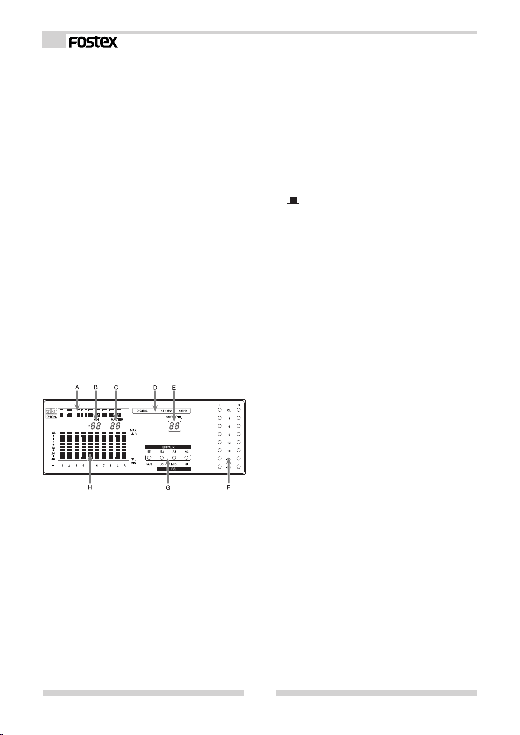
29. Display/status/meter section
(D) Digital in status display section
This displays the [DIGITAL IN] setting in the setup
mode, and the external digital input signal status.
For details, refer to [IN/OUT of digital signals] in
“Normal mix mode” on page 18.
(E) Scene number display
The current scene number is displayed here.
Refer to [Scene memory mode] on page 30 for
details.
(F) LED level meter display section
The output level of the STEREO BUSS is displayed
here. When ST OUT ON/OFF is switched to OFF
( ), all LEDs will blink to indicate that no signal is
output from the ST OUT L, R connectors.
This level meter has a peak hold function, which
is adjustable in the setup mode. The initial state
peak hold time is set to 1.0 sec. For details, refer
to “Setup mode” on page 33.
(G) Status indicator
Using the channel parameter edit mode explained
later, what is currently setup can be confirmed
by the dot display. Items to be set can be selected
with the PAN/EQ key or the EFF/AUX key. Refer
to [Channel parameter edit mode] on page 20 for
details.
(H) LCD level meter
In normal mix mode, this indicates channels 1 ~ 8
input levels and the stereo buss level. In the
various edit modes, the setup status will be
displayed. The peak hold function is not provided
in the LCD level meter.
(A) Character display section
Names of the scene memory or various edit modes
are displayed.
(B) CHANNEL fader display section
In channel parameter edit mode, the INPUT fader
position of the selected channel is displayed in
units of 00 ~ 99. Nothing will be displayed in the
initial state and the normal mix mode.
(C) MASTER fader display section
The MASTER fader position is displayed in units
00 ~ 99.
30. TRIM knob
These knobs are for adjusting the input gain to match
the sound source connected to INPUT 1 ~ 8. These
can be adjusted within the range of -50dBu ~ -10dBu
for MIC INPUT 1 ~ 4, -30dBu ~ +10dBu for LINE INPUT
1 ~ 4 and -40dBu ~ +4dBu for INPUT 5 ~ 8.
31. Input jack 5 ~ 8
Line level sound sources can be connected to channels
5 ~ 8 input jacks (TRS phone jacks). In the initial
setup, the input mode of INPUT 5-6 and INPUT 7-8
are set to stereo so that stereo output sound sources
can be connected.
The input mode can also be set for monaural by the
setup mode. Trim is adjustable to match the output
of the sound source that is connected (Adjusting
range: -40dBu ~ +4dBu). To setup of the input mode,
refer to “Setup mode” on page 33.
32. Insert jack 1 ~ 4
These jacks are used when using a compressor/limiter
on mic sound sources at inputs 1 ~ 4. For details,
refer to “Connecting peripheral equipment” on page
9.
6
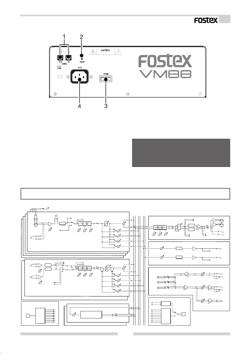
Rear panel sectin
Model VM88 Owner’s Manual
1. Digital in/out jacks
Digital signals (S/P DIF or ADAT) from external digital
equipment can be input to these DIGITAL IN jacks
and then assigned to the desired input channel. S/P
DIF or ADAT digital signals can be output from the
DIGITAL OUT connectors. For details, please refer to
“Connecting peripheral equipment” on page 9 and
“In/out of digital signals” explained in “Normal mix
mode” on page 18.
2. RESET switch
This switch resets the CPU inside VM88.
Refer to page 8 for details.
Block Diagram
-48V
PHANTOM (SETUP)
INSERT
CH 2
CH 3
CH 4
CH5 INPUT
(+4dBu~-40dBu)
CH6 INPUT
(+4dBu~-40dBu)
CH5/6
CH7/8
DIGI IN
DIGI IN
MIC
(-10dBu~-50dBu)
LINE
(+10dBu~-30dBu)
CH 1
TRIM
TRIM
S/P DIF
or
ADAT
DECODE
(SETUP)
TRIM
A/D
A/D
From DIGI IN
To CH1
To CH2
To CH3
To CH4
To CH5
To CH6
To CH7
To CH8
(-10dBV)
A/D
From DIGI IN
DIGI IN
(SETUP)
To DIGI OUT
To DIGI OUT
MONO/STEREO
(SETUP)
EFF 1-2
EFF 1
MASTER
To METER
10kHz
1kHz
100Hz
LO
MID
To METER
10kHz
1kHz
100Hz
LO
MID
ASP
DIGITAL EFFECT
CH ON
GAIN
HI
PRE/POST
CH ON
GAIN
HI
PRE/POST
EFF MUTE
3. POWER switch
The On/Off power switch.
4. AC IN connector [AC IN]
Plug-in the power cable included with the VM88 here.
< NOTE >
If the VM88 is not to be used for long periods (more
than one month) be sure to remove the power cable
plug from the wall outlet.
EFF
ST
AUX
12
R
12
L
PAN
EFF 1
EFF 2
AUX 1
AUX 2
PAN
EFF 1
EFF 2
AUX 1
AUX 2
ST MASTER
10kHz
1kHz
100Hz
LO
MID
HI
AUX MASTER
AUX 1
MASTER
AUX 2
MASTER
MON
From AUX 1
AUX 1
From AUX 2
AUX 2
From ST
MON SEL
S/P DIF
From ST
ENCODE
From CH1-A/D
From CH2-A/D
From CH3-A/D
From CH4-A/D
ADAT
From CH5-A/D
ENCODE
From CH6-A/D
From CH7-A/D
From CH8-A/D
To DIGI OUT
D/A
ST OUT
D/A
D/A
D/A
To METER
To MON
To MON
To MON
CH ON
ST MASTER
ST
DIGI OUT
DIGI OUT
S/P DIF
ADAT
(SETUP)
AUX 1 OUT
(-10dBV)
AUX 2 OUT
(-10dBV)
ST OUT
(+4dBu)
ST OUT
(-10dBV)
SUB IN
(-10dBV)
MON OUT
(-10dBV)
PHONES
(100mW)
L
R
L
R
L (M)
R
L (M)
R
7
Model VM88 Owner’s Manual
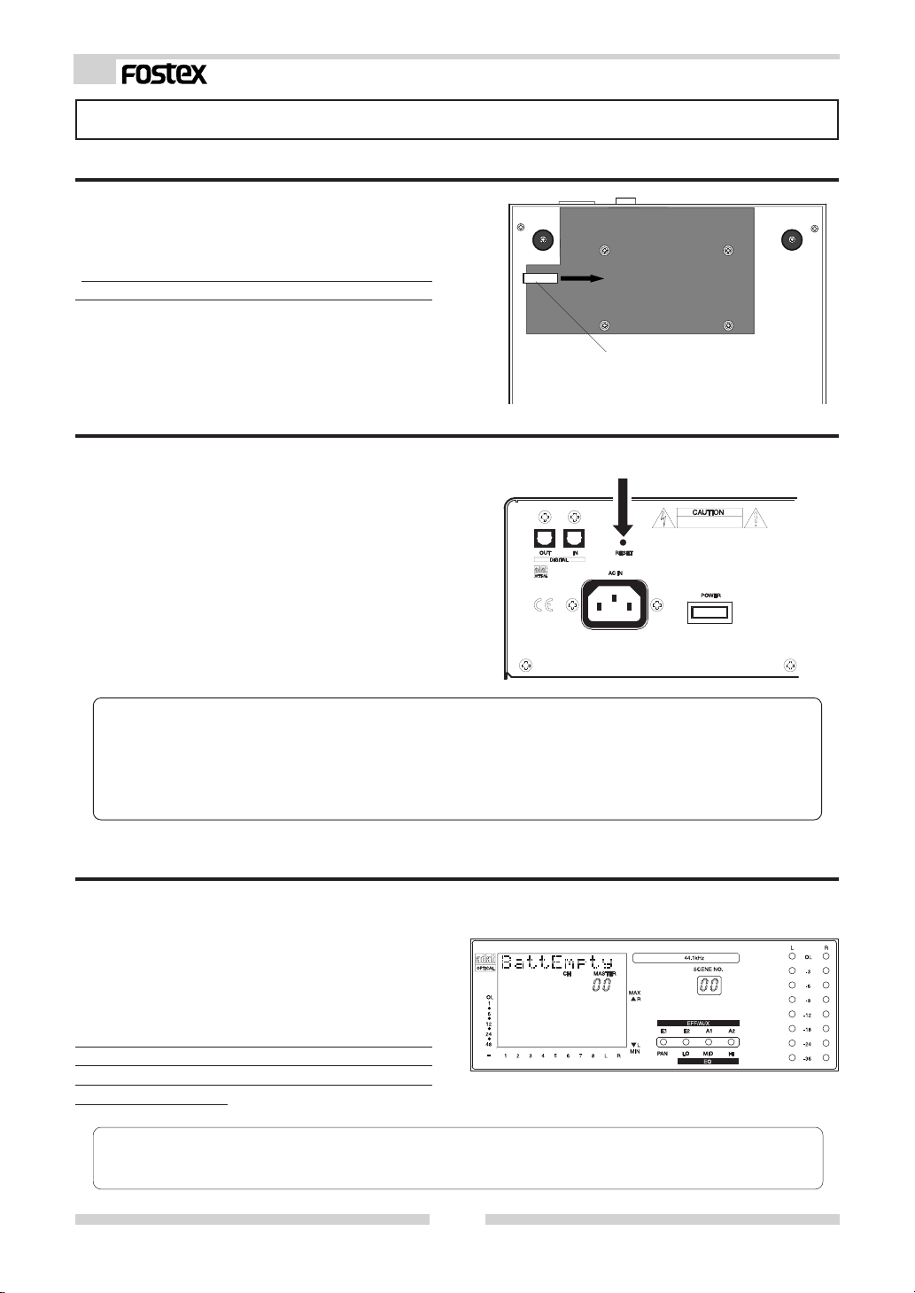
Before Operation (IMPORTANT Be sure to read below before first using your VM88.)
* Remove the insulation paper
The VM88 uses a memory back up battery
inside. You will find a piece of insulation
paper attached to avoid current dissipation.
When using the VM88 for the first time, turn ON
the power and then remove the insulation paper.
The insulation paper is easily removed by
pulling it in direction of arrow as shown at
right.
* Reset of VM88
Insulation paper
It is possible for the computer to malfunction at power ON/OFF or by electro induction noise from lightning. In this happens,
switch the power ON/OFF to the VM88 several times.
If it does not return to normal operation,
press the rear panel [RESET] switch with a
slender ball point pen or similar tool. This
returns all settings to the initial figures setup
at shipping from the plant.
This procedure can be used to clear all stored
scene memories.
<Please remember!>
If reset is executed with the INPUT and MASTER raised simultaneous with start up of this unit, the
LEVEL ADJUST key/FADER ADJUST key will blink. This indicates that the VM88 has entered the
Level Adjust Mode/Fader Adjust Mode because of the difference between present fader position
and the fader position at start up following reset. To exit from this mode, retard all faders to the
[MIN] position, and the key blinking will stop.
RESET switch
* Internal battery for the memory back up
The internal battery has a life expectancy of
about two years. When the battery runs low
and its voltage falls below a certain level, the
warning message "BattEmpty" will appear in
the display. If you continue to use the unit
an old battery, your stored scene memories
will be lost when the power is turned off.
Do not try to replace the battery yourself as there
are no user-serviceable parts inside. Please ask
your Fostex distributor or an authorized service
station to do the job.
<Please remember!>
There is an automatic internal battery voltage check function in the VM88.
Refer to [Setup mode] on page 33.
8
Model VM88 Owner’s Manual
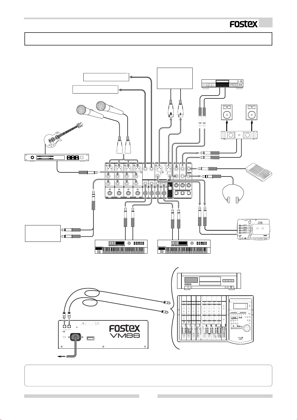
Peripheral Equipment Connection
Sound sources and external equipment shown in the examples below can be connected to the VM88’s
input and output connectors. When connecting external equipment to the in/out connectors, be
sure to switch off power to the VM88.
External Equipment
External Equipment
Other Mixing Console
or Amplifier
CD Player
Monitor Speaker System
Guitar & Guitar Processor
Compressor/Limitter
Microphones
+10+10
MICMIC
2:HOT2:HOT
LINE
INSERT
1
LINELINE
MICMIC
-30-30
[dBu][dBu]-10-10
-50-50
INPUTINPUT
MICMIC
2:HOT
2
LINELINE
MICMIC
-30-30
+10+10
-10-10
-50-50
[dBu][dBu]
Keyboard
Amplifier
AUX SENDAUX SEND
MICMIC
MICMIC
2:HOT
2:HOT
21
LINELINELINELINE
INSERT
INSERTINSERT
3
4
LINELINE
LINELINE
MICMIC
MICMIC
+10+10
-30-30
+10+10
-30-30
+4+4 -40-40
+4+4 -40-40
[dBu][dBu]-10-10
-50-50
[dBu][dBu]-10-10
-50-50
[dBu][dBu]
[dBu][dBu]
TRIMTRIM
R
L
2:HOT
2:HOT
BAL/+4dBu
L
UNBAL/-10dBVUNBAL/-10dBV
INPUTINPUT
765
+4+4 -40-40
+4+4 -40-40
[dBu][dBu]
[dBu][dBu]
L (MONO) (MONO)L (MONO) (MONO)
PHONESPHONES
RR
R
GAINGAIN
GAIN
OFF
ON
8
STST OUT OUT
GAIN
MAXMAXMINMIN-∞+6+6
+6+6
-∞
[dB][dB]
[dB][dB]
MON SELMON SEL
AUX 2AUX 1ST
MONITMONITOROR
Foot Switch
FOOTFOOT SW SW
MON INMON IN MON OUTMON OUT
STST OUT OUT
Headphones
multitracker
X-14
Multitracker
Keyboard
Digital Master Recorder
CAUTIONCAUTION
RESETRESET
ININOUTOUT
DIGITDIGITALAL
AC INAC IN
OPTICALOPTICAL
POWERPOWER
DIGITAL MULTITRACKER
FD-8
AC outlet
<Please remember!>
If external digital equipment to be connected is provided with only COAXIAL (RCA pin jack) type IN/
OUT connectors, use the optional Fostex COP-1/96k optical-coaxial converting adaptor sold separately.
9
Model VM88 Owner’s Manual
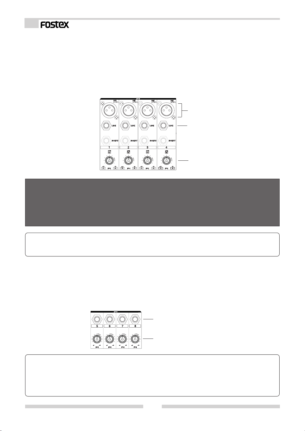
(1) INPUT 1 ~ 4 connectors
Two types of connectors - Canon connectors (XLR-3-31 type) and TRS phone jacks - are provided for INPUT 1 ~
4 and either can be used to input of signals depending on the application. Refer to < NOTES > below.
Canon connectors that comply to mic/line levels and microphones are connected here in most cases. Condenser
type mics requiring phantom power can be connected because phantom power is provided to these connectors.
Also, you can trim within a range of -50dBu ~ -10dBu to match the equipment connected.
Line level sound sources can be plugged into the TRS phone jacks, which complies to both TRS type and common
phone plugs. The same as with the Canon connectors, trim is possible within a range of -30dBu ~ +10dBu to
match the output level of the equipment connected.
Canon connectors (balanced: 2 HOT)
TRS phone jacks (balanced)
TRIM knobs for use the INPUT 1-4
< NOTES >
* The Canon connector and TRS phone jack of each channel cannot be used in parallel. Use either input only.
A malfunction could occur if both are used at the same time.
* Be sure to switch off the power to the VM88 or switch off the phantom power when plugging or unplugging
microphone cables.
* Do not switch on the phantom power when using a dynamic mic. This could damage the microphone.
< NOTICE>
When using condenser microphones that require phantom power, first check “On/Off setting of phantom
power” explained later in “Setup mode” (Initially set at off). For details, refer to “Setup mode” on page 33.
(2) INPUT 5 ~ 8 connectors
INPUT 5 ~ 8 are TRS phone jacks and line level sound sources can be plugged in here. The input mode (stereo
or monaural) of the input connectors INPUT 5-6 and 7-8 can be changed depending on the application. Initially,
the input mode of INPUT 5-6 and 7-8 are set to stereo.
The input jacks comply to both TRS type and common phone plugs, and just as with INPUT 1 ~ 4, the input level
can be trimmed within a range of -40dBu ~ +4dBu to match the output level of the equipment connected.
TRS phone jacks (balanced)
TRIM knobs for use the INPUT 5-8
< Please remember! >
The input mode (stereo/mono) of INPUT 5-6 and 7-8 can be changed to match the application. Initially,
they are set for stereo and thus stereo signals can be input to INPUT 5-6 and 7-8.
For example, if INPUT 5-6 are set to mono, the INPUT 5 jack will be effective and a signal input to INPUT 5
will be simultaneously sent to channels 5 and 6. For details on setup of the input mode, refer to “Setup
mode” on page 33.
10
Model VM88 Owner’s Manual
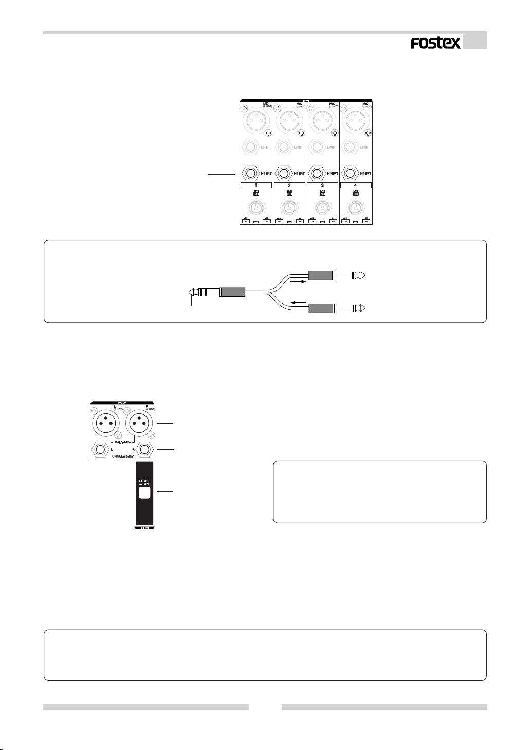
(3) INSERT 1 ~ 4 jacks
INSERT 1-4 jacks are used when a compressor/limiter is applied to the mic input signals into INPUT 1-4, as
shown in the previous connecting example. The in/out are TRS phone jacks and standard input/output levels
are -10dBV.
TRS phone jacks
< Please remember! >
When connecting a compressor/limiter to the INSERT jack, be sure to use the connecting cables shown
below.
T o VM88 INSER T jack
RING: RETURN
TIP: SEND
To compressor/limiter input jack
To compressor/limiter output jack
(4) ST OUT L, R connectors
Balanced output Canon connectors (XLR-3-32 type) and unbalanced output phone jacks are provided for ST
OUT L, R, either of which can be selected depending on the application. Amplifiers and other mixers are
connected here. The standard output level is balanced output +4dBu and unbalanced output -10dBV.
Canon connectors (balanced: 2 HOT)
Phone jacks (unbalanced)
< Please remember! >
Outputs from the ST OUT L, R connectors can be
ST OUT ON/OFF switch
switched on/off with the ST OUT ON/OFF switch.
For details, refer to “Normal mix mode” on page
15.
(5) DIGITAL IN/OUT jacks (Rear panel)
A digital signal (S/P DIF or ADAT) from external digital equipment is input to the DIGITAL IN jack; these signals
can be applied to any input channel. From the DIGITAL OUT jack, mixed signal, which is the same as those
output from the ST OUT L, R connectors can be output in digital (S/P DIF) or the INPUT 1-8 input signals can be
directly output in digital (ADAT) signal. If ADAT is selected, the input signal prior to being affected by the INPUT
fader and EQ can be output digitally.
< Please remember! >
If a digital signal (S/P DIF or ADAT) is to be input to VM88 or a digital signal (S/P DIF or ADAT) is to be output
from the VM88, it will be necessary to setup the system clock and DIGITAL IN or DIGITAL OUT modes.
For details, refer to “Normal mix mode” on page 15 and “Setup mode” on page 33.
11
Model VM88 Owner’s Manual
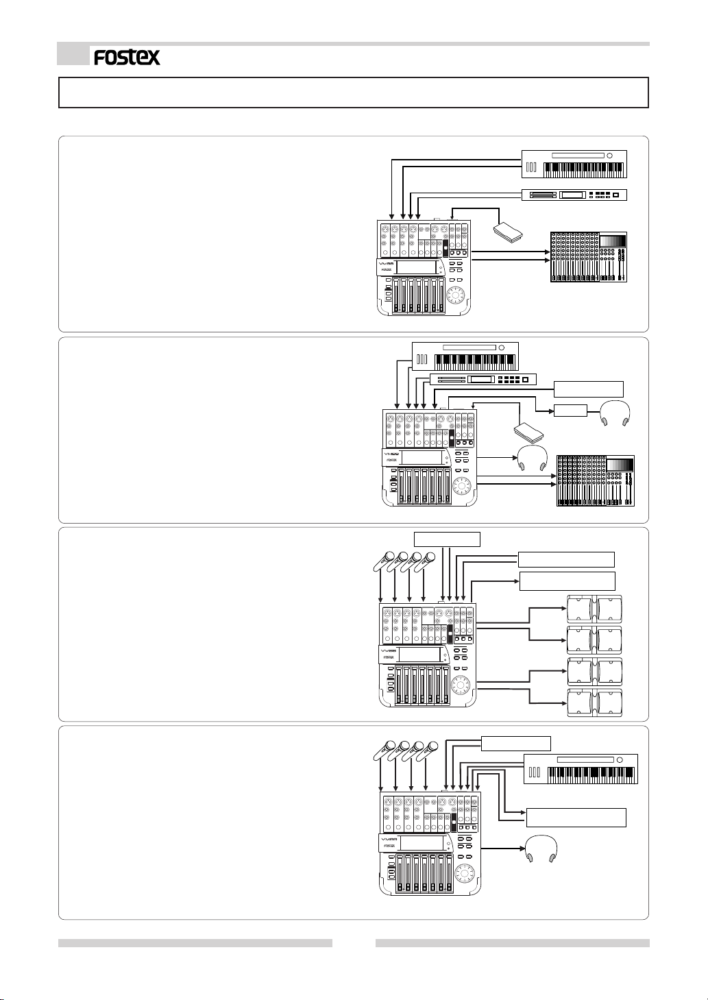
Application Examples
The following are actual examples in application of VM88 and could be helpful in your application.
< Example 1 > :
As a live performance keyboard mixer
The VM88 can be used as a submixer for
keyboards and sound source modules. Scene
memory in which the sound balance has been
set can be switched with a foot switch.
Model 8051
VM88
Keyboard
Sound module
PA mixer
< Example 2 > :
As a live performance keyboard mixer with sync
In addition to the keyboard and sound source
module mix, playback of ADAT sound can be
mixed simultaneously. By outputting a track
containing a click from the AUX SEND jacks via
the pre-fader, a cue can be sent to the monitor
headphone and the drummer.
< Example 3 > :
As a small PA mixer
The VM88 can be used as a PA mixer with two
channels of monitor sends.
Balance can be pre-stored in the scene memory
and sequentially called in accordance to the
script.
< Example 4 > :
As a recording mixer (overdub) for an ADAT
recorder
Overdubbing of ADAT or one-time recording of
8 tracks is possible by setting Digital In to [ADATAll Ch] and Digital Out to [ADAT Dir].
Playback monitor level is adjusted via the fader
and the recording level by the TRIM knob.
VM88
VM88
CD player
AUX
ADAT
AUX 1
AUX 2
Keyboard
Sound source
ADAT
ADAT
Headphone
Sound module
Model 8051
Sound module
Recorder
SPA11
(main)
SPA11
(monitor)
Digital recorder
D-108 etc.
Digital Recorder
D-108 etc.
PH50
PA mixer
Keyboard
Headphone
12
VM88
 Loading...