

Page 1
Owner’s Manual
Model
Eight Channel Digital Mixer with DSP Effects
Introduction
Thank you very much for purchasing the Fostex VM08.
The VM08 digital mini-mixer does all internal signal processing digitally.
The input section consists of eight analog input channels including four for
microphones. The output section, in addition to normal analog outputs such
as two channel stereo and a headphone output, also has S/P DIF digital optical output with a 44.1 kHz sampling frequency: and 20 bit quantization.
The internal buss is two channel stereo L/R, plus an independent Effects buss
(1, 2) and an AUX buss (1, 2).
In addition to each input channel, an EQ is also provided for the master output. The VM08 also incorporates high performance DSP multi-effects on two
channels that operate by A.S.P. (Fostex Advanced Signal Processing Technology*) exclusively developed by Fostex. This allows a wide range of equalizing
and effects processing. All settings, including mix and effects settings, are
stored in scene memory, and a desired scene memory can be recalled instantaneously. Although small and lightweight, the VM08 is a high performance
unit. Please read this manual carefully before operation to understand all
functions of the VM08.
* See page 18 for more details on the A.S.P. (Fostex Advanced Signal Processing Technology).
Page 2
Model VM08 Owner’s Manual
CAUTION
RISK OF ELECTRIC SHOCK
DO NOT OPEN
CAUTION: TO REDUCE THE RISK OF ELECTRIC SHOCK,
DO NOT REMOVE COVER (OR BACK).
NO USER - SERVICEABLE PARTS INSIDE.
REFER SERVICING TO QUALIFIED SERVICE PERSONNEL.
"WARNING"
"TO REDUCE THE RISK OF FIRE OR ELECTRIC
SHOCK, DO NOT EXPOSE THIS APPLIANCE TO RAIN
OR MOISTURE."
SAFETY INSTRUCTIONS
1. Read Instructions - All the safety and operating instructions
should be read before the appliance is operated.
2. Retain Instructions - The safety and operating instructions should
be retained for future reference.
3. Heed Warnings - All warnings on the appliance and in the
operating instructions should be adhered to.
4. Follow Instructions - All operating and use instructions should
be followed.
5. Water and Moisture - The appliance should not be used near
water - for example, near a bathtub, washbowl, kitchen sink,
laundry tub, in a wet basement, or near a swimming pool, and
the like.
6. Carts and Stands - The appliance should be used only with a
cart or stand that is recommended by the manufacturer.
An appliance and cart combination should be moved with care.
Quick stops, excessive force, and uneven surfaces may cause
the appliance and cart combination to overturn.
7. Wall or Ceiling Mounting - The appliance should be mounted to
a wall or ceiling only as recommended by the manufacturer.
8. Ventilation - The appliance should be situated so that its location
or position dose not interfere with its proper ventilation. For
example, the appliance should not be situated on a bed, sofa,
rug, or similar surface that may block the ventilation openings;
or, placed in a built-in installation, such as a bookcase or cabinet
that may impede the flow of air through the ventilation openings.
CAUTION:
TO PREVENT ELECTRIC SHOCK, MATCH WIDE BLADE
OF PLUG TO WIDE SLOT, FULLY INSERT.
ATTENTION:
POUR EVITER LES CHOCS ELECTRIQUES,
INTRODUIRE LA LAME LA PLUS LARGE DE LA FICHE
DANS LA BORNE CORRESPONDANTE DE LA PRISE
ET POUSSER JUSQU' AU FOND.
The lightning flash with arrowhead symbol,
within an equilateral triangle, is intended to alert
the user to the presence of uninsulated
"dangerous voltage" within the product's
enclosure that may be of sufficient magnitude
to constitute a risk of electric shock to persons.
The exclamation point within an equilateral
triangle is intended to alert the user to the
presence of important operating and
maintenance (servicing) instructions in the
literature accompanying the appliance.
9. Heat - The appliance should be situated away from heat sources
such as radiators, heat registers, stoves, or other appliances
(including amplifiers) that produce heat.
10. Power Sources - The appliance should be connected to a power
supply only of the type described in the operating instructions or as
marked on the appliance.
11. Grounding or Polarization - The precautions that should be taken
so that the grounding or polarization means of an appliance is not
defeated.
12. Power Cord Protection - Power supply cords should be routed so
that they are not likely to be walked on or pinched by items placed
upon or against them, paying particular attention to cords at plugs,
convenience receptacles, and the point where they exit from the
appliance.
13. Cleaning - The appliance should be cleaned only as recommended
by the manufacturer.
14. Nonuse Periods - The power cord of the appliance should be
unplugged from the outlet when left unused for a long period of
time.
15. Object and Liquid Entry - Care should be taken so that objects do
not fall and liquids are not spilled into the enclosure through
openings.
16. Damage Requiring Service - The appliance should be serviced by
qualified service personnel when:
A. The power supply cord or the plug has been damaged; or
B. Objects have fallen, or liquid has been spilled into the appliance;
or
C. The appliance has been exposed to rain; or
D. The appliance does not appear to operate normally or exhibits
a markedchange in performance; or
E. The appliance has been dropped, or the enclosure damaged.
17. Servicing - The user should not attempt to service the appliance
beyond that described in the operating instructions.
All other servicing should be referred to qualified service personnel.
2
Page 3

Model VM08 Owner’s Manual
Precautions (please read before use)T able of Contents
Precautions............................................3
Names and Functions...........................4
Before Operation...................................6
Remove the insulation paper.......................6
Caution when powering ON.........................6
Reset of VM08.................................................6
Internal battery for the memory back up...6
Peripheral Equipment Connection.....7
Application Examples...........................9
Initial State of the VM08.......................11
Normal Mix Mode.................................12
Channel Parameter Edit Mode..........14
Setup method for PAN setting....................14
EQ setup method..........................................15
Setup method of the effect send level.......15
Setup method of the aux send level..........16
PRE/POST setup method............................17
Effect Edit Mode...................................18
About the effect types.................................19
Selecting the effect type..............................20
Effect parameter settings............................21
Muting an effect...........................................21
Effect parameter details..............................22
Power Supply
* When unplugging the AC adaptor from the
outlet, be sure to grasp the adaptor.
Attempting to unplug it by pulling on the
AC cable may damage the wiring.
* It is dangerous to use any power cable that
is cut or frayed. If the power cable is
damaged, immediately stop using it, and
have it repaired.
* Do not plug in or unplug the AC adaptor
with wet hands. Doing so may result in
dangerous electric shock.
* Do not open the unit or touch any parts
inside. Doing so may result in a
dangerous electric shock, and could
damage the unit.
* Do not let water or other liquids,
flammable materials, or metal objects such
as pins get in side the unit.
These things may cause electric shock or
short circuit the VM08, and damage it.
If the VM08 should become wet, unplug
the AC adaptor from the AC outlet, and
contact your authorized service station.
Location
Scene Memory Mode..........................24
Storing a scene memory.............................24
Recalling a scene memory..........................24
Level adjust..................................................25
Fader adjust.................................................25
Directly recalling a scene memory...........26
Clearing a scene memory...........................26
Setup Mode..........................................27
Making settings in setup mode..................27
Details of the setup menu...........................27
Input 5/6 input setting...................................27
Input 7/8 input setting...................................27
Fader fix setting...............................................28
Channel fader recall setting...........................28
Master fader recall setting..............................28
Foot switch setting...........................................28
Battery check....................................................28
Specifications......................................29
Avoid using the VM08 in the following
locations:
* Locations of extreme low or high tempera-
tures, or extreme changes in temperature.
* Locations with excessive moisture or dust.
* Locations where direct sunlight falls for an
extended time, or near a stove or other
source of heat.
* Locations where electrical voltage varies.
* Unstable locations or where there is heavy
vibration.
* Near strong magnetic fields (on top of a
television or speaker).
3
Page 4
Model VM08 Owner’s Manual
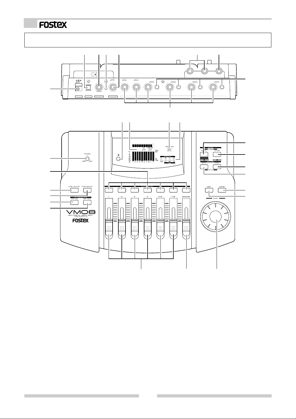
Names and Functions
28
27
26
25
24
23
2345
7
1
9V
AD-9B
1
ONLY
OUT
S/P DIF
FOOT SW AUX SEND
DC IN
2
RESET
5
8
6
6/5
8/7
TRIM
4
-10 -50
INPUT
3
TRIM
-10 -50
67
ST OUTR
L
PHONES
TRIM
-10 -50
1
TRIM
-10 -50
2
8
9
10 11 13
12
14
EQ
15
16
17
18
19
1. AC adaptor connector
Connect the AC adaptor, included in the accessory kit, to a wall AC socket and plug the adaptor
output cable to this jack (Be sure to use the adaptor included in the VM08 package).
2. S/P DIF optical output connector
The same signal output from the ST OUT L/R jack
is output here as digital audio signal in the S/P
DIF format.
3. Foot switch connecting jack
A foot switch (Fostex Model 8051) is plugged in
here. The foot switch function can be changed by
the [SETUP mode] explained later. The initial setting recalls the scene memory. Refer to page 27
for details.
202122
4. RESET switch
This switch resets the CPU inside VM08. Refer to
page 6 for details.
5. AUX send jack
AUX SEND level signals, adjusted in the channel
parameter edit mode, are output here. Refer to
pages 8 and 17 for details.
6. STEREO OUT L, R jack
The mixed signal is output to the MTR, stereo monitor system or to other mixers. Output level is adjusted by the MASTER fader.
7. Headphone jack
The monitoring headphone is connected here.
Use the PHONES control to adjust the sound level.
4
Page 5

8. TRIM knob
Input gain is adjusted with this TRIM knob for each
sound source connected to input jacks 1 ~ 4.
The input level is adjustable over a wide range
from line level down to mic level.
9. INPUT jacks
External sound sources are input here.
INPUTS 1 ~ 4 comply to mic/line and input gain
can be adjusted with the TRIM knob. INPUT's 5/6
and 7/8 are exclusively for line level signals.
10. Contrast adjusting knob
The LCD display contrast is adjusted with this
knob.
11. LCD display
Various figures are displayed here. Refer to [Initial state of VM08] in page 11 for details.
12. Scene number display
The current scene number is displayed here.
Refer to [Scene memory mode] on page 24 for details.
13. Status indicator
Using the channel parameter edit mode explained
later, what is currently setup can be confirmed by
the dot display. Items to be set can be selected
with the PAN/EQ key or the EFF/AUX key. Refer
to [Channel parameter edit mode] on page 14 for
details.
14. Scene Recall key
This is pressed to recall the scene memory explained later. Refer to [Recall of the scene memory]
on page 24 for details.
15. Scene Store key
This is pressed to store a scene memory. Refer to
[Storing the scene memory] on page 24 for details.
16. Effect 2 key
This is pressed to select the EFF 2 effects type or
the parameter to be edited. Also, if this key is
pressed while pressing the EXIT key, muting of EFF
2 can be switched ON/OFF. Refer to [Effect edit
mode] on page 18 for details.
17. Effect 1 key
This is pressed to select the EFF 1 effects type or
the parameter to be edited. Also, if this key is
pressed while pressing the EXIT key, muting of EFF
1 can be switched ON/OFF. Refer to [Effect edit
mode] on page 18 for details.
18. Enter key
This is used to accept the current mode setting.
This key will setup scene memory (page 24), the
setup mode (page 27) and also the setup of effects type (page 18). Please refer to their respective explanation for details.
19. Exit key
This is used to exit from all modes but the normal
mix mode. This key works for the channel parameter edit mode (page 14), the effects edit mode
Model VM08 Owner’s Manual
(page 18), the scene memory mode (page 24) and
the setup mode (page 27). Refer to their respective explanation for details.
20. Data encoder
This dial is rotated to make settings such as setup
of PAN and EQ. This dial works in the channel
parameter edit mode (page 14), the scene memory
mode (page 24) and the effects edit mode (page
18). Refer to their respective explanations for
details.
21. Master fader
This adjusts the master level of signal output from
the STEREO OUT L, R jacks and S/P DIF OUT.
22. Input fader
Signal levels of sound sources connected to each
INPUT jack can be adjusted with these faders. Input faders 5/6 and 7/8 controls both channels at
the same time.
23. EFF/AUX select key
The channel parameter edit mode is entered when
this key is pressed and EFFECT send output and
AUX send output can be adjusted. Refer to [Channel parameter edit mode] on page 14 for details.
24. PAN/EQ select key
The channel parameter edit mode is entered when
this key is pressed to setup of PAN and EQ. Refer
to [Channel parameter edit mode] on page 14 for
details.
25. Fader adjust key
This key warns by blinking if a fader position drifts
or sound volume is accidentally changed at switch
ON of power or at recall of the scene memory. Use
this key to enter the fader adjust mode to manually adjust the fader position. Refer to [Fader adjust mode] on page 25 for details.
26. Level adjust key
This key will blink together with of the FADER
ADJUST key. The level adjust mode is entered
when this key is pressed so the sound level can be
matched to the present fader position. Refer to
[Level adjust mode] on page 25 for details.
27. Channel On/Channel Select key
The channel to be edited can be selected while in
the channel parameter edit mode. In other modes,
channel ON/OFF is possible. Refer to [Normal mix
mode] on page 12 and [Channel parameter edit
mode] on page 14 for details.
28. Headphone volume
This adjusts the monitor headphone sound volume.
5
Page 6
Model VM08 Owner’s Manual
Before Operation (IMPORTANT Be sure to read below before first using your VM08.)
* Remove the insulation paper
The VM08 uses a memory back up battery inside. You
will find a piece of insulation paper attached to avoid
current dissipation. When using the VM08 for the first time,
turn ON the power and then remove the insulation paper. The
insulation paper is easily removed by pulling it in direction of arrow as shown at right.
* Caution when powering on
There is no power switch in VM08.
Power is switched ON/OFF simply by plugging and
unplugging the VM08’s AC adaptor plug.
Be sure to switch off power to the monitor amplifier connected to the VM08 output or fully retard
the input level controls to prevent damage to connected speakers when
switching power ON/OFF in this
manner.
Insulation paper
9V
AD-9B
ONLY
OUT
FOOT SW
DIGITAL
DC IN
ST OUTR
7
5
1
8
6
2
6/5
8/7
RESET
AUX SEND
TRIM
4
3
-10 -50
INPUT
L
1
2
TRIM
TRIM
-10 -50
-10 -50
RESET switch
PHONES
TRIM
-10 -50
AC adaptor
< Caution >
If the VM08 is not to be used for a long time, be sure
to unplug the AC adaptor from the wall outlet.
* Reset of VM08
It is possible for the computer to malfunction at power ON/OFF or by electro induction noise from lightning. In this happens, switch the power ON/OFF to the VM08 several times. If it does not return to normal
operation, press the rear panel [RESET] switch with a slender ball point pen or similar tool. This returns all
settings to the initial figures setup at shipping from the plant. This procedure can be used to clear all
stored scene memories.
<Please remember this!>
If reset is executed with the INPUT and MASTER raised simultaneous with start up of this unit, the
LEVEL ADJUST key/FADER ADJUST key will blink. This indicates that the VM08 has entered the
Level Adjust Mode/Fader Adjust Mode because of the difference between present fader position
and the fader position at start up following reset. To exit from this mode, retard all faders to the
[MIN] position, and the key blinking will stop.
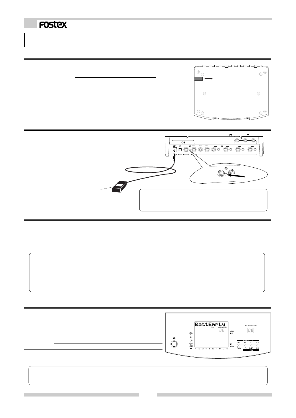
* Internal battery for the memory back up
The internal battery has a life expectancy of about two years.
When the battery runs low and its voltage falls below a certain level, the warning message "BattEmpty" will appear in
the display. If you continue to use the unit an old battery,
your stored scene memories will be lost when the power is
turned off. Do not try to replace the battery yourself as there are
no user-serviceable parts inside. Please ask your Fostex distributor or an authorized service station to do the job.
<Please remember this!>
There is an automatic internal battery voltage check function in the VM08.
Refer to [Setup mode] on page 27.
6
Page 7
Model VM08 Owner’s Manual
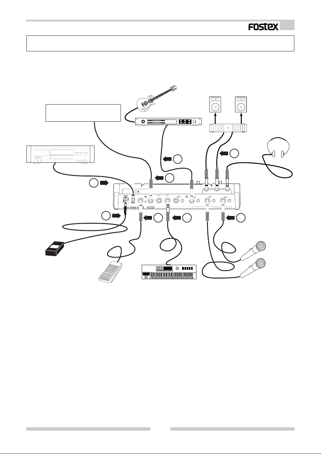
Peripheral Equipment Connection
The schematic below is an example of external equipment connected to the VM08.
To avoid possible speaker damage, please be sure to unplug the AC adaptor when connecting
external equipment to the IN/OUT connectors of the Fostex VM08.
Monitor Speaker
External Effect Unit/External Mixer etc.
Digital Master Recorder
AC Adaptor
Footswitch
Guitar & Guitar Processer
Amplifier
Monitor headphone
1
2
1
2
4
7
8
6/5
8/7
Synthesizer
ST OUTR
L
5
6
TRIM
4
3
TRIM
-10 -50
-10 -50
INPUT
PHONES
1
2
TRIM
TRIM
-10 -50
-10 -50
235
Microphone
7
9V
AD-9B
ONLY
DC IN
RESET
OUT
FOOT SW
AUX SEND
DIGITAL
6
1) ST.OUT L, R jack
These are unbalanced phone jacks where an external monitor (amplifier+ speaker) or analog master recorder can be connected. The standard output level is -10dBV.
2) INPUT 1 ~ 4 jacks
These are unbalanced phone jacks for microphones and sound sources such as a guitar. TRIM knobs are
provided for each jack by so input levels can be adjusted to match the sound source, from microphone
input to line level signals.
3) INPUT 5/6 (INPUT 7/8) jacks
TRS type phone jacks for connecting line level sound sources.
As shown in the schematic, both stereo and mono output sound sources can be connected. For either type
signals, the input mode can be selected using the VM08’s setup mode. Refer to [Setup mode] on page 27
for setup of the input mode. Refer to next page for details in preparing and wiring the TRS phone plug.
The standard input level is -6dBV.
4) AUX SEND 1/2 jack
TRS type phone jacks where external effects and mixers can be connected. Two channels, namely, AUX
SEND 1 and 2 are output here. One or two external units can be connected. See the next page for details
in preparing and wiring a TRS phone plug. The standard output level is -10dBV.
7
Page 8
Model VM08 Owner’s Manual
5) FOOT SW jack
This is an unbalanced type phone jack. An unlatch type foot switch (Fostex Model 8051) can be plugged in
here. Operations using the foot switch are selectable in the [Setup mode]. Refer to [Setup mode] on page
27 for details.
6) DC IN connector
Plug-in the tip of the power cord of the exclusive AC adaptor (AD-9B) here and plug the adaptor into a
household AC wall outlet. Since the VM08 does not have a power switch, ON/OFF of power is done by
plugging and unplugging the AC adaptor from the AC wall outlet. If you don’t plan on using the VM08 for
some length of time, the AC adaptor must be unplugged from the AC wall outlet.
7) S/P DIF OUT connector
The same signals output from ST OUT L, R are output here as digital (S/P DIF) signals.
Signals mixed in an external digital master recorder connected here can be recorded in digital as shown in
the schematic. If external digital equipment to be connected is provided with only COAXIAL (RCA pin jack)
type IN/OUT connectors, use the optional Fostex COP-1/96k optical-coaxial converting adaptor sold separately.
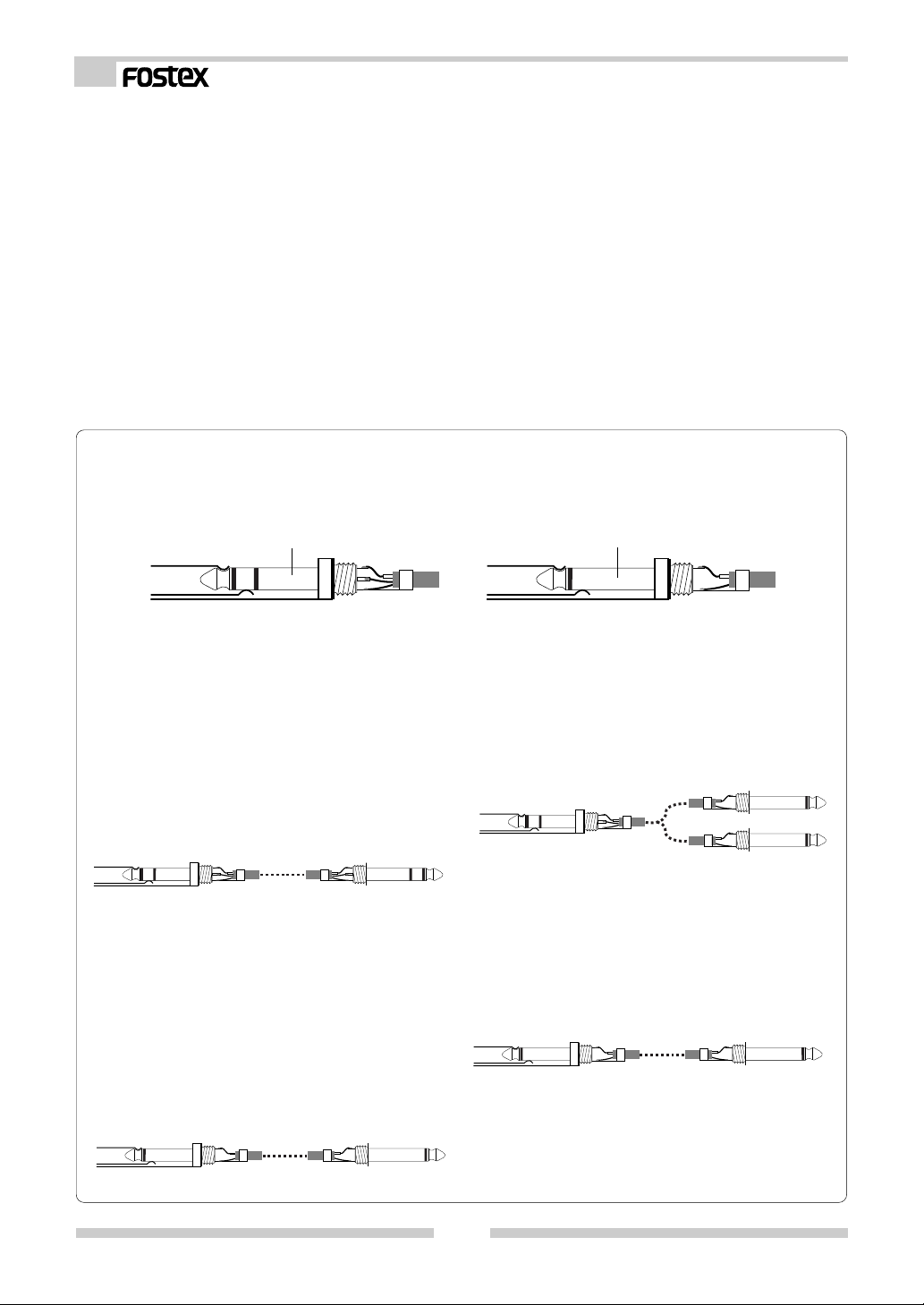
* INPUT 5/6 (7/8) and AUX SEND 1/2 jacks
TRS type jacks used at INPUT 5/6, TRS type jacks used at INPUT 5/6 (7/8) and AUX SEND 1/2, and
TRS phone plugs or unbalanced phone plugs can be connected here, as shown below. The phone plug
should be wired as shown below.
TRS Phone plug Phone plug
INPUT 5/6, INPUT 7/8 jacks:
* How to input a stereo signal:
In order to input a stereo output signal to channels 5/6 or 7/8, a stereo cable with a STEREO
phone plug wired as shown in the schematic
should be used. Set the INPUT 5/6 input mode or
INPUT 7/8 input mode in the setup mode to [Stereo]. The L signal of the stereo input signal will
be applied to channel 5 (or 7) and the R signal to
channel 6 (or 8). Refer to [Setup mode] on page
27 to setup the input mode.
VM08 side
* How to input a monaural signal:
In order to input a monaural output signal to
channels 5/6 or 7/8, an unbalanced phone plug,
as shown in the schematic, is used for the connection and the INPUT 5/6 input mode or INPUT 7/8 input mode in the "setup mode" is set
to [In 5 > Mono] (or [In 7 > Mono]).
The monaural signal will be simultaneously input to channels 5 and 6 (or 7 and 8). When
setting the input mode, refer to [Setup mode]
on page 27 for details.
Music source side
AUX SEND OUT 1/2 jack:
* Connecting two external equipment:
Wire the TRS phone plug to two phone plugs as
shown in the schematic to connect two separate
pieces of equipment to AUX SEND 1/2.
By doing so, the AUX SEND 1 signal and AUX SEND
2 signal will be separately output to the two.
VM08 side
External Equipment
* Connecting a single external equipment:
In order to connect a single external piece of
equipment to the AUX SEND 1/2 jack, the unbalanced phone plug is connected as shown in the
schematic.
This will output only the AUX SEND 1 signal.
VM08 side
External Equipment
VM08 side
Music source side
8
Page 9
Model VM08 Owner’s Manual
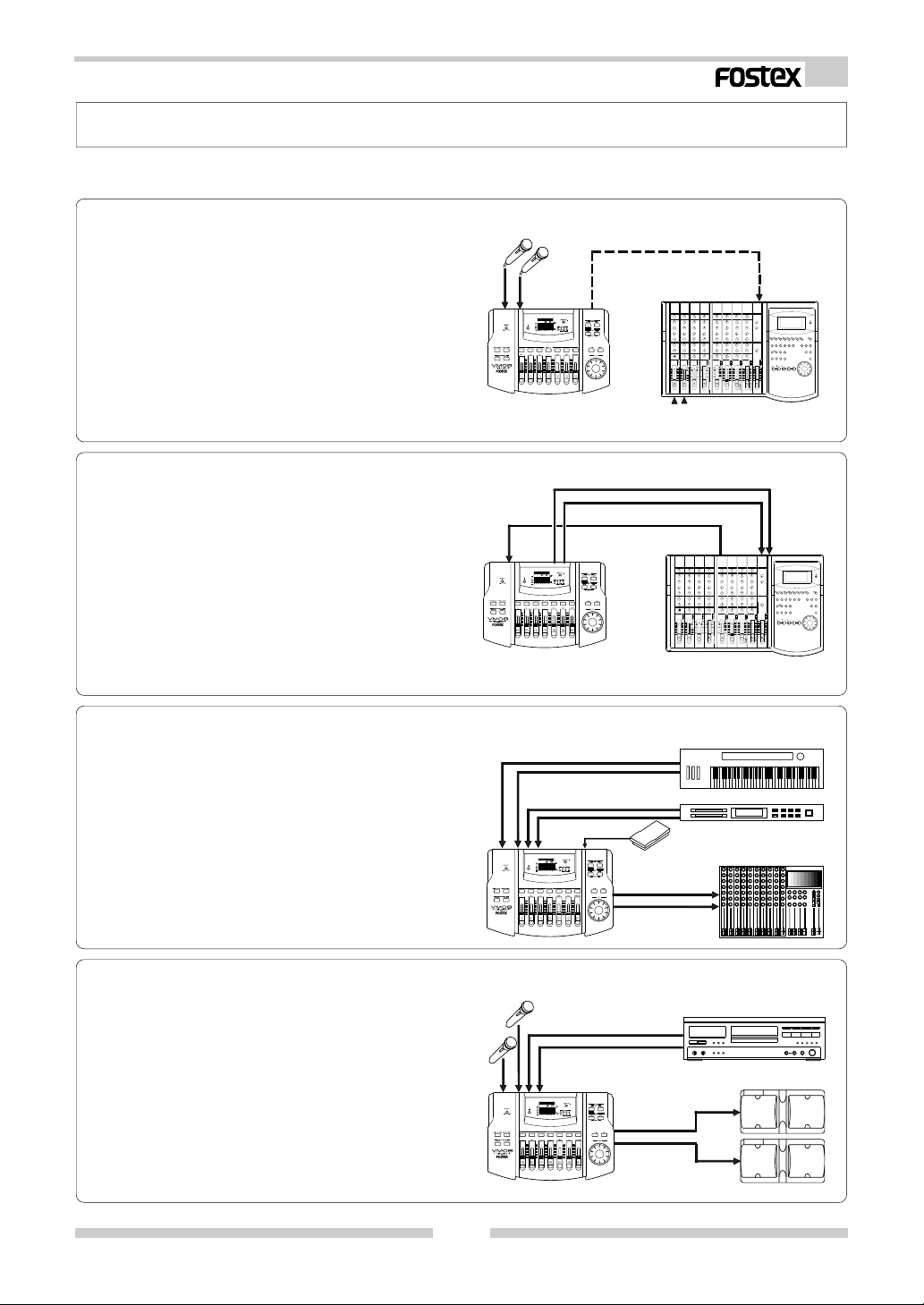
Application Example
The following are actual examples in application of VM08 and could be helpful in your application.
<Example-1> : To expand the FD-8 analog simultaneous recording channel
The FD-8 analog simultaneous recording track can
be extended to "4" by connecting the FD-8 DATA
IN jack to the VM08 S/P DIF OUT jack.
You can also take advantage of the high quality DSP
multi-effects contained in the VM08 when record-
S/P DIF
EQ
ing.
VM08
<Example-2> : To use as a MONO IN/STEREO OUT effects
The VM08 internal DSP multi-effects can be utilized
for high quality external processing by connecting
the VM08 ST OUT L/R to the FD-8 AUX RTN L/R
jack. If the input channel fader is set to "0" and the
EFF BUSS is sent via the pre-fader, the effects sound
INPUT
ST OUT L, R
EQ
only can be output from ST OUT.
VM08
<Example-3> : For use as a sub-mixer for a live keyboard player
The VM08 can be utilized as a sub mixer for a keyboard and sound source module. A scene memory
in which the sound volume balance had been set
can then be switched with the foot switch.
S/P DIF signal
Analog In
AUX SEND
Keyboard & Sound Module
DATA IN
FD-8
AUX RTN L/R
FD-8
VM08
<Example-4> : To use as a small facility mixer
In a sequence such as MC only -> MC+Music ->
Music, by pre-storing the sound volume balance in
the scene memory, the scene memory can be sequentially called up.
VM08
9
EQ
EQ
8051
PA Mixer
CD player
SPA11
Page 10

Model VM08 Owner’s Manual
<Example-5> : For one take live studio recording
You can use the VM08 to send the mixed digital
audio via S/P DIF to a DAT or PC with Digital In.
You can also add the internal digital effect when
mixing audio.
<Example-6> : To produce original Remix
You can send the remixed sound of the Sampler
and CD player with the internal digital effect to a
DAT recorder via the S/P DIF.
VM08
<Example-7> : To do you own Sound Track Video Editing
You can add your favorite background music, original sound effects and narration when editing videos.
VM08
EQ
EQ
S/P DIF
S/P DIF signal
Audio signal
Keyboard
PC audio board with
digital in
S/P DIF
OPEN/
DAT
Sampler & CD player
POWER
DISP
TIME
ON
DISP
LEVEL
OFF
MARGIN
RESET
OPEN/
CLOSE
PNO
789
LOC
D-15 DIGITAL MASTER RECORDER
MEM LOC
PHONES
START ID SEARCH
AUTO
BLANK
INSTANT
CUE
SET UP
SEARCH
START
1023
MIN MAX
F FWD
STOP PLAY
RECORD
REWIND
REMOTE
Camera
AUTO-ID
654
AUTO
START
REC
SKIP
END
9P-REMOTE
OPTICALON
DIGITAL
OFFLOCAL
INPUTGPI
Video
DAT
WRITE
ERASE
ID
SELECT
RAM
JOG
PREVIEW
SCRUB
/SHTL
/REPEAT
QUIT
INPUT
CHASE
MONITOR
/RCL
EXECUTE
OFFSETRENUM
MUTE
/SET
CAL
CAL
CH2
CH1
EXT
48kHz
44.1kHz
INTANALOG
INPUT
MIN MAX
MIN MAX
SAMPLING FREQCLOCK
LEVEL
EQ
VM08
<Example-8> : As a practice aid for your musical instruments
You can use the VM08 to practice your musical instruments with added effects on top of backing
tracks recorded on MTR’s such as the X-14.
VM08
10
Video
signal
VTR
X-14
000
multitracker
X-14
EQ
AMP
Page 11

Model VM08 Owner’s Manual
VM08 Initial State
The following explains what to do the first time you use the VM08 right out of the shipping
carton. When the AC adaptor is plugged into the AC wall outlet and the power cord plugged
into the DC IN connector, power will be applied and the VM08, and the display/operating panel
lamps will light in the modes explained below. This is the same sa when the CPU is reset by
pressing the RESET switch.
* Character display section:
Following the <<FOSTEX>> ->
<<VM08>> display, [Init.Mix] will be
displayed. If the INPUT fader/MASTER fader is manipulated in this
state, [E] will be lit behind the
[Init.Mix] display (Refer to next
page).
* Channel fader display section:
After entering the channel parameter edit mode, the INPUT fader
position of the channel selected by
the CH ON/CH SEL key will be indicated by numbers 00 ~ 99. In
the initial state, nothing is displayed. For details, refer to [Channel parameter edit mode] on page
14.
* Level display section:
In the channel parameter edit mode and
fader adjust mode, the signal level input
to each INPUT jack for channels 1 ~ 8
will be indicated by the pre-fader. In
other words, regardless to the INPUT
fader set position, the input signal level
will be constantly displayed. Because,
INPUT of channels 1 ~ 4 must handle low
level signals such as from a microphone,
a TRIM knob is provided for each channel to adjust the gain. The best gain level
can be obtained by watching this display.
Channels L and R display indicates signal levels at the STEREO OUT L, R jacks
but in the initial state, the level meter
will not fluctuate since the MASTER fader
is set to the [MIN] position. Should the
input and output signal levels reach the
[OL] (over load) level, the sound will distorted, so care must be taken in adjusting the TRIM adjust/INPUT fader.
* MASTER fader section:
The MASTER fader position is indicated by numbers 00 ~ 99.
The initial setting is [00] which is
the initial mix setting (The fader
[MIN] position).
CH
MASTER
OL
1
6
12
24
48
12345678LR
* CH ON/CH SEL key:
The channel to be edited can be selected with this
key in the channel parameter edit mode and, in
other modes, each channel can be switched ON/
OFF. In the initial state, all channels will be indicated as ON and the key LED's will all light.
* Scene number display section:
The current active scene number (00
~ 20) is displayed.
In the initial setting, [00] will be displayed.
SCENE NO.
MAX
R
L
MIN
EQ
* Status indicator:
The dot selected by the channel parameter edit mode will
light but nothing lights in the
initial state. Refer to [Channel parameter edit mode] on
page 14 for details.
< Please remember this! >
* The scene number of the sber of the ssber of the scene memory which the user can setup are [00] ~
[20] but the preset scene [00] cannot be changed. Refer to page 24 for details on the scene memory.
* If, for some reason, you would like to return the VM08 setting to the factory default figure, refer to
[Reset of VM08] on page 6.
11
Page 12

Model VM08 Owner’s Manual
Normal Mix Mode
Normal mix mode means each INPUT fader/MASTER fader is active, and the ON/OFF of each
channel is operational so basic mixing functions can be executed. When the VM08 is in [Initial
state of VM08], as explained in the previous section, if the INPUT fader of the channel to which
a signal is being input (Example: The channel 1 INPUT fader if a sound source is connected to
INPUT 1.) and the MASTER fader is raised, signals will be output from the rear panel STEREO
OUT L, R jacks and the S/P DIF optical connector. Also, if headphones are connected to the
PHONES jack, the same signal will be heard in the headphones. The headphone monitoring
sound volume can be adjusted by the top panel PHONES knob. Throughout these operation,
the VM08 LCD display will change as explained below.
* Character display section:
[E] lights following the [Init.Mix] display. This [E] symbol
means "edit" and indicates that the setting had been changed
from the initial state. At this point of operation, the initial
state had been changed by this moving the INPUT and MASTER faders.
* Level display section:
The input signal level
will be displayed for
channels 1 ~ 4, 5/6 and
7/8 and the output
level in accordance to
the MASTER fader position indicated by L and
R.
* The MASTER fader display section:
The present position to which the MASTER fader is set will be indicated by
numbers 00 ~ 99. The standard level
setup number is [80].
* Scene number display
section:
The current scene number
will be displayed.
* Status display section:
Nothing will light up in the
normal mix mode.
All channels are ON.
< Useful information !>
* When the MASTER fader is rotated, its position will be digitally indicated in the MASTER fader section
in the display and the sound volume will vary. A digital indication of the INPUT fader position will
be displayed in the [Channel parameter edit mode] explained in the next section. For details, refer to
[Channel parameter edit mode] on page 14.
* The relationship between the actual gain and the INPUT fader and MASTER fader is, 00= -∞, 80dB=0dB,
99=+6dB.
12
Page 13

Model VM08 Owner’s Manual
<CAUTION>
If [Fader Fix mode], discussed below, in the [Setup mode] is set to [ON], no signal will be output even
though the fader is moved. The [FADER FIX mode] is set to [OFF]. For details refer to [Setup mode] on
page 27.
Mute of the various input channel/master output:
Mute ON/OFF of channels 1 ~ 4, 5/6, 7/8 and master output can be done using the CH ON/CH
SEL key. Normally, the CH ON/CH SEL keys for channels 1 ~ 4, 5/6, 7/8 and MASTER are all ON
(key LED is lit). Therefore, when the CH ON/CH SEL key of the channel you wish to mute is
pressed, sound from that channel only will be muted (the CH ON/CH SEL key LED of the channel
that was pressed will be extinguished). Mute ON/OFF alternates with each pressing of the CH
ON/CH SEL key.
Mute ON channel (LED is off).
<Useful information !>
In addition to operating with the CH ON/CH SEL key,
mute ON/OFF of master output is also possible using
the foot switch (Optional Model 8051).
In the foot switch functional setting is set for [Mute
function of master output] in the [Setup mode] of
the VM08, mute can be executed by stepping on the
foot switch. For details on the [Setup mode], please
refer to page 27.
<Useful information !>
In the normal mix mode, if the position of the INPUT fader/MASTER fader before switching off power
is different from when power is switched on (refer to schematic below), the FADER ADJUST and LEVEL
ADJUST key LED’s (red) will flash. This is because the fader setting before switching off power is in
memory, and the VM08 is indicating that fader and level adjustment is possible.
The fader position can be reset to the position prior to switching off power, and the level position can
be deliberately set to the present sound volume setting.
* To return to the setting before switching off power:
Press the flashing FADER ADJUST key (It will enter the fader adjust mode). Subsequently, adjust each
fader position by referring to [Fader adjust mode] explanation.
* To set to the present fader position:
Press the flashing LEVEL ADJUST key and the VM08 will enter the level adjust mode.
Then setup by following [Level adjust mode] on page 27.
If it is not necessary to match the fader positions, the FADER ADJUST key flashing will extinguished
after all faders are moved and the VM08 will return to the normal mix mode.
<Setting before switch off of power>
<Setting at switch on again of power>
13
Page 14

Model VM08 Owner’s Manual
Channel Parameter Edit Mode
Twelve items, as shown in list below, can be set by the channel parameter edit mode. Regardless of the VM08’s current mode, their respective edit modes can be entered by executing the
key operations listed below. To exit from the channel parameter edit mode, press the EXIT key.
Setting Item
Setup of PAN (sound image)
Setup of LO-EQ
Setup of MID-EQ
Setup of HI-EQ
Level setup of EFF SEND 1
Level setup of EFF SEND 2
Level setup of AUX SEND 1
Level setup of AUX SEND 2
PRE/POST setup of EFF SEND 1
PRE/POST setup of EFF SEND 2
PRE/POST setup of AUX SEND 1
PRE/POST setup of AUX SEND 2
Executing Key
When the PAN/EQ key is repeatedly pressed, the setup item will
alternately switch. In the initial
state, the channel 1 PAN setup will
be displayed.
When the EFF/AUX key is repeatedly pressed, the setup item will
alternately switch. In the initial
state, the channel 1 EFF SEND 1
level setup will be displayed.
If the EFF/AUX key is pressed
while pressing on the EXIT key, the
setup item will alternately switch.
In the initial state, the display will
be PRE/POST setup of channel 1
EFF SEND 1.
Changing the channel Changing the setup content
Channel 1 is selected in
the initial state and the
channel to be edited is selected by pressing each respective CH ON/CH SEL
key. The CH ON/CH SEL
key LED (green) of the selected channel will blink.
Setup is changed by utilizing
the DATA encoder.
<Useful Information!>
When selecting a desired item, each time the respective key is pressed, it will move to the next item, and
if the key is held down, it will change one item backward in the setup item list.
Setup method for PAN setting
Balance of channels 1 ~ 4, 5/6, 7/8 and STEREO MASTER signals must be setup.
1. Press the PAN/EQ key to light up the [PAN] dot
in the status display section.
The LCD will display the following:
* Character display section:
[1-Pan: C] will be displayed. Now PAN of channel 1
can be setup, and this indicates that the present
PAN setting is for centering the sound image (C).
3. The number is adjusted with the DATA encoder.
The number can be changed within the range
of [L10] ~ [C] ~ [R10] and the sound image
position will change accordingly. The graphic
display will also change at the same time.
[L10] ~ [L1] ~ [C] ~ [R1] ~ [R10] will be displayed.
EQ
Blinking Lit
2. Press the desired CH ON/CH SEL key and
select the channel to be adjusted.
CH ON/CH SEL key of the selected channel will
blink.
EQ
The digit moves up and down.
<Useful information!>
When the DATA encoder is activated to set PAN,
its position will be displayed digitally in 21 steps
within the range of [L10] ~ [C] ~ [R10] but the
actual change in sound will be continuous
(smooth). If channels 5/6 and 7/8 had been selected, balance between the two channels can
be setup. If the MASTER had been selected, balance between L and R can be setup.
14
Page 15

Model VM08 Owner’s Manual
Setup method for EQ setting
Individual setup of the low region (LO), mid region (MID) and high region (HI) for the signals of
channels 1 ~ 4, 5/6, 7/8 and STEREO MASTER.
<Useful information!>
The equalizer specs of VM08 are, 100Hz +/- 18dB (shelving type) for LO-EQ, 1kHz +/- 18dB (peaking type) for MID-EQ, and 10kHz +/- 18dB (shelving type) for HI-EQ. Each can be adjusted in 1dB
steps.
1. [LO], [MID] or [HI] dots in the status display
section will light by successively pressing the
PAN/EQ key.
The LCD display will show the following:
Example: Character display section when [LO] is
made to light.
[1-LO: 0] will be displayed. In this condition, LOEQ of channel 1 can be adjusted and is the indication that the present LO-EQ setting is flat (0dB).
EQ
Blinking
Lit
2. The channel you wish to adjust is selected by
pressing the desired CH ON/CH SEL key.
The selected channel CH ON/CH SEL key will
blink.
3. The number is set with the DATA encoder.
The number will change in the range of [-18dB]
~ [+18dB] and the equalized sound will also
change. The graphic display will also change at
the same time.
[+18] ~ [+1] ~ [0] ~ [-1] ~ [-18] will be displayed.
EQ
Digit will move up and down.
<Useful information!>
When channels 5/6 and 7/8 are selected, the
two channels will be simultaneously equalized.
If MASTER is selected, both L and R will be equalized at the same time.
Setup method of the EFFECT SEND level
In the following, the effects send level of the signal in the channel to which effects is to be
applied is adjusted before sending it to the DSP multi-effects (EFF 1/EFF 2) contained in the
VM08. It is also possible for the effect send signal to select either POST (post fader) or PRE (prefader). The VM08 is set to POST (post fader) in the initial state.
<Useful information!>
* The EFFECT SEND signal adjusted in channels 1 ~ 4, 5/6 and 7/8 is sent to the VM08 internal DSP
multi-effects (EFF1 or EFF 2). The operating explanation used here is based on the effects type
([Norm. HALL] in EFF 1, [CHORUS] in EFF 2) which are preset in EFF 1/EFF 2. Twenty-eight preset
effects for EFF 1 and 38 types for EFF 2 are provided in the VM08.
To select other effects or adjust effect parameters, refer to [Effect edit mode] on page 18.
* Because EFFECT SEND is set in the post fader (the signal controllable by the INPUT fader) in the
initial state, in this explanation it is necessary for the INPUT fader to be raised on the channel in
which the EFFECT SEND level is to be adjusted. In addition, the MASTER fader to adjust output
level from ST OUT L, R is also raised. To setup of the EFFECT SEND PRE/POST, see page 17.
15
Page 16

Model VM08 Owner’s Manual
1. Status display section [E1] or [E2] dots are lit
by pressing the EFF/AUX key.
The LCD will display the following:
Example: Character section when [E1] is lit.
[1-Eff1:00] is displayed. Channel 1 EFFECT SEND
1 level can now be adjusted. The present EFFECT
SEND 1 level setting is "dry" (0).
3. Adjust the number with the DATA encoder.
The number will change in a [0] ~ [99] range
and the depth of effects will also change. The
graphic display will change at the same time.
[00] ~ [99] will be displayed.
EQ
EQ
Bar graph extends in step by blinking.
<Useful information!>
Lit
2. Select the channel to be adjusted by pressing
the desired CH ON/CH SEL key.
If channels 5/6 or 7/8 are selected, the two
channels will be set at the same time. If MASTER is selected, the effect send level master can
be adjusted and the L, R meter used to indicate
the level.
Setup method of the AUX SEND level
Adjusting the signal level output from the VM08 rear panel AUX SEND jack (1/2).
The adjusted signal is sent to external equipment (external effects and monitor amplifier) from
the AUX SEND jack. The same as with the EFFECT SEND signal, either POST or PRE can be
selected for the AUX SEND signal. The VM08 is set to POST in the initial state. To change the
setting, please see below [Setup of PRE/POST].
1. Light up the [A1] or [A2] dots in the status
display section but pressing the EFF/AUX key.
The LCD will display the following:
Example: The character display section with light
up [A1].
[1-Aux1:00] is displayed. Now, channel 1 AUX
SEND 1 level can be adjusted. This also indicates
that the present AUX SEND 1 level setting is MIN
(00).
3. Adjust the number with the DATA encoder.
The number will change in the [0] ~ [99] range
and depth of effects will also change. The graphics display will change at the same time.
[00] ~ [99] will be displayed.
EQ
2. Press the desired CH ON/CH SEL key and
select the channel you wish to adjust.
EQ
Lit
Bar graph extended in step with blinking.
<Useful information!>
When channels 5/6 or 7/8 are selected, the two
channels will be set at the same time. If MASTER is selected, the effect send level master can
be adjusted and the L, R meter used to display
the level.
16
Page 17

Model VM08 Owner’s Manual
PRE/POST setup method for EFFECT SEND/AUX SEND
In the procedure here, the effect send and AUX send signals are setup for PRE (pre-fader) or
POST (post fader). In the initial state, EFFECT SEND 1, 2, AUX SEND 1, 2 are all setup for POST
(post fader).
<Useful information!>
PRE (pre-fader) means that the signal is obtained before the INPUT fader and is not affected by the
INPUT fader. POST (post fader) means that the signal is obtained following the INPUT fader and is
affected by the INPUT fader. In other words, in the PRE setting, although the INPUT fader is at MIN,
the EFFECT SEND or AUX SEND levels can be adjusted but in the POST setting, no signal can be sent
if the INPUT fader is at MIN.
1.While pressing the EXIT, press the EFF/AUX key
to light up [E1], [E2], [A1] or [A2] in the status
display section.
The LCD will display the following:
Example: The character display section with [E1]
is lit
[1-E1: Post] is displayed. Now, channel 1 EFFECT
SEND 1 PRE/POST can be setup. This indicates
that the present EFFECT SEND 1 PRE/POST is set
at POST.
Blinking
Lit
2. Press the desired CH ON/CH SEL key and
select the channel you wish to adjust.
3. Adjust the number with the DATA encoder.
[Pre] or [Post] can be selected.
The graphic display will also change at the same
time.
Changes to [Post] or [Pre].
If [Pre] is selected, the blinking 3 digits move upward.
<Useful information!>
When channels 5/6 or 7/8 are selected, the two
channels will be set at the same time. If MASTER is selected, all channels will be at the same
time.
17
Page 18

Model VM08 Owner’s Manual
Effect Edit Mode
The VM08 offers high quality ambient effects by employing the A. S. P. (Fostex Advanced Signal
Processing Technology), which is exclusively developed by Fostex. With the A. S. P., you can
obtain an incomparably clean and high density Hall Reverb, overwhelmingly clear Room Reverb and wonderfully hi-fidelity Plate Reverb. In addition to these typical Reverbs, the VM08
provides not only various practical algorithms such as Delay, Chorus, Flanger and Pitch Bend,
but some combinations of these are also available, e.g., Delay+Reverb.
* A. S. P. (Fostex Advanced Signal Processing Technology)
The A. S. P. is an exclusive new digital effect processing technology designed by
Fostex. This method extracts maximum efficiency from the limited DSP power.
It achieves an overwhelmingly high density Early Reflection sound and wonderfully smooth High Dump response through the H. F. A. (Harmonic Feedback
Algorithm). Also, it carries out an elaborate reverb simulation with clear sounds
through the H. D. L. P. (Hi-Density Logarithmic Processing), which eliminates
the mutual interference between the numerous integrated delay modules and
reduce the impurity and girt of the sound.
* H. F. A. (Harmonic Feedback Algorithm)
There is one of indispensable elements in the natural echo called “Early Reflection Sound,” which is
usually sacrificed in commercial reverb products in order to reduce costs. (In practice, the Early
Reflection Sound means the very first reverberated sound that bounces back from walls, floors and
ceilings of concert halls). The entire reverb sound quality depends on this Early Reflection Sound
and how closely it can resemble the real echo. The H. F. A. is an algorithm that enables the effect unit
to reproduce a clear and natural Early Reflection Sound by applying an ideal harmonic feedback to
each delay module.
* H. D. L. P. (Hi-Density Logarithmic Processing)
The reverb sounds consist of lots of small delay elements combined in a complex way, which are
produced by many delay modules inside the effect unit. In order to obtain smooth and comfortable
reverb sounds, it is very important to efficiently organize the relationship between each delay module and minimize negative mutual interference. The H. D. L. P. is a technology which applies efficient
logarithmic processing to each delay module, so that they can work in the most efficient way in order
to eliminate harmful reverb elements and roughness. This makes it possible to establish high density
and transparent sounds.
Before the partical operation, we will briefly discuss the effect functions here such as Reverb,
Delay, Chorus, and Flanger, which are integrated in the VM08.
Reverb:
The so called Reverb effect consists of various reflection sounds mixed together. For example, when you
clap your hands in a tunnel, you will hear the sound
linger even after you stop clapping your hands. This
is the Reverb.
The sounds we normally hear in daily life have three
types of sounds mixed together, i.e., “Direct sound,”
“Early Reflection sound” and “Late Reflection sound.”
The Direct sound means the sound directly reaches
the ears from the sound source. The Early Reflection
sound means the sound that comes after the Direct
sound and has rebound off the wall of the tunnel up
to a few times. The Late Reflection sound means that
the sound rebounds many times long after the Direct
sound has disappeared. Our ears normally hear the
“Direct sound” - “Early Reflection sound” - “Late Reflection sound” in the order.
Delay:
This is the effect to added a delayed sound to the
original sound. You can obtain a richer sound or completely change the original source sound by using the
Delay.
Chorus:
This makes the one original sound appear to have
many sources. The Chorus is used to widen or thicken
the original sound.
Flanger:
The Flanger is one of applications of the Delay. This
is used to create a sound like a jet airplane ascending
or descending.
18
Page 19

Model VM08 Owner’s Manual
About the effect types
The VM08 contains two independent DSP multi-effect units; EFF 1 and EFF 2.
A variety of effect types are preset for each effect unit. By selecting a suitable effect type, you
can process the sound as you wish. You can also edit the parameters of the selected effect type
to create your own effect sounds.
The following 28 effect types are preset for EFF 1. The 38 effect types shown on the next page
are provided for EFF 2, and these include the same 28 effect types as EFF 1.
Effect types preset for EFF 1
Name Parameter type Explanation
1 Norm HALL REVERB Standard hall reverb; detailed and transparent, with a moderate amount of early
2 Pres HALL REVERB Hall reverb with presence and definition.
3 Wet HALL REVERB Hall reverb with restrained high-frequency and a refreshing atmosphere.
4 NoER HALL REVERB All-purpose hall reverb with no early reflections, and even decay of all frequencies.
5 Lo-F HALL REVERB Hall reverb with lingering low-frequency reverberation.
6 STADIUM REVERB Stadium reverb characterized by long early reflections.
7 Auditrium REVERB Reverb simulating an auditorium with suppressed reverberation.
8 Space HALL REVERB Reverb with a long pre-delay, creating the impression of an extended space.
9 Norm ROOM REVERB Room reverb simulating a moderate space with some sparkle.
10 Dead ROOM REVERB Room reverb simulating a narrow and dead room. Adding a slight amount will give warmth
11 Pres ROOM REVERB All-purpose room reverb, with good definition and few early reflections.
12 DrumBOOTH REVERB Room reverb simulating a drum booth.
13 GARAGE REVERB Room reverb simulating a narrow and live space like a garage, with crisp presence.
14 NormPLATE REVERB Modern-sounding plate reverb with wide bandwidth.
15 Old PLATE REVERB Standard plate reverb with the character of older plate units.
16 PresPLATE REVERB Plate reverb with good definition and extended high-frequencies.
17 Wet PLATE REVERB Plate reverb with a gentle character.
18 DigiPLATE REVERB Plate reverb that emphasizes a digital character, with metallic early reflections.
19 NormVOCAL REVERB All-purpose hall reverb with no early reflections, and uniform decay at all frequencies.
20 PresVOCAL REVERB Short reverberation with extended high frequency is added to the early reflections of an
21 SoloVOCAL REVERB Plate-like reverb is added to a spacious short delay. This blends well with any genre of
22 Arena VOC REVERB Gentle reverb is added to spacious stadium-type early reflections.
23 Arena CHO REVERB Short reverb with extended high frequency is added to spacious stadium-type early
24 KARAOKE REVERB All-purpose reverb (karaoke style) that makes any vocal sound professional.
25 MnDL-HALL DLY+REVERB A combined effect of mono delay and hall reverb.
26 MnDL-PLT DLY+REVERB A combined ef fect of mono delay and plate reverb.
27 PnDL-HALL DLY+REVERB A combined effect of panning delay and hall reverb.
28 PnDL-PLT DL Y+REVERB A combined effect of panning delay and plate reverb.
reflections.
to the sound.
ideal vocal booth. Since this adds sparkle to the sound, it is effective when you wish to
bring the vocal to the forefront.
music.
reflections. Effective on chorus parts.
19
Page 20

Model VM08 Owner’s Manual
Effect types preset for EFF 2
Name Parameter type Explanation
1
1--28 are the same effect types as the EFF 1 presets listed on the preceding page. (For details refer to the preceding page.)
~
28
29 MonoDELA Y DELAY Mono delay
30 PanDELA Y DELAY Panning delay
31 MonoBpmDL BPM DELA Y Mono delay. Specify BPM and note value to set the delay time.
32 PanBpmDL BPM DELAY Panning delay. Specify BPM and note value to set the delay time.
33 Short DL SHORT DELAY Short delay that allows you to set the delay time precisely.
34 DOUBLING DOUBLING Doubling that allows you to set separate delay times for L and R.
35 CHORUS CHORUS Produces a chorus effect. A doubling effect can also be added.
36 FLANGE FLANGE Produces a flanging effect.
37 MonoPITCH MONO PITCH Pitch shift adjustable in a +/-2 octave range.
38 DlyPITCH DELAY PITCH Pitch shift with a feedback delay, allowing strange effects to be produced.
Selecting the effect type
Here's how to select the effect type for EFF 1 or EFF 2.
Press this to set the effect type
for EFF 1.
* As described earlier in "Normal mix mode," raise the INPUT fader of a channel to which a
signal is being input and raise the MASTER fader, so that the sound is heard at an appropriate
level.
* As described earlier in "Setting the effect send level," raise the EFF 1 SEND level or the EFF 2
SEND level for the channel(s) to which you wish to apply the effect.
1.If you wish to set EFF 1, press the EFF EDIT
mode EFF 1 key. To set EFF 2, press the EFF 2
When the EFF 2 key is pressed:
With the initial settings, [CHORUS] will appear.
Press this to set the effect type
for EFF 2.
key.
With the initial settings, the following displays
will appear.
When the EFF 1 key is pressed:
With the initial settings, [Norm HALL] will appear.
2. Use the DATA encoder to select the effect type.
EQ
The effect types listed in the foregoing tables
will appear in succession. When an effect type
appears, it will be blinking. The blinking indi
cates that the effect type has not yet been
selected.
20
Page 21

3. Press the [ENTER] key.
The effect type will be finalized, and the
parameter setting screen will appear.
The default (initial) parameter values will be
displayed.
Effect parameter settings
Here's how to set the effect parameters.
Model VM08 Owner’s Manual
Details on the parameters are given in the following section, "Parameter settings."
4. To exit Effect Edit mode, press the EXIT key
twice in succession.
You will return to Normal Mix mode.
< Note >
When you press the ENTER key to finalize the
effect type, the sound will be muted for an
instant.
1. If the effect parameter that you wish to adjust is
not displayed, press the EFF 1 key (or the EFF 2
key) twice.
One of the parameters of that effect type will
appear.
2.Press the EFF 1 key (or the EFF 2 key) several
times to display the desired parameter.
The parameters that appear will differ,
depending on the effect type that is selected.
3. Use the DATA encoder to adjust the value.
For details on the meaning and range of each
parameter, refer to "Effect parameter details"
on the next page.
4. If you wish to adjust another parameter, repeat
from <step 2>.
5. When you are finished making settings, press
the EXIT key twice to exit Effect Edit mode.
<Useful Information!>
The parameter display will change as you repeatedly press the EFF 1 (or EFF 2) key. If you
hold down the key for a certain length of time,
the parameter display will go back to the previous screen.
<Useful Information!>
When the effect parameter being edited is "Delay Time" or "BPM," you can also use the ENTER key or
a foot switch to make the setting by tapping, as an alternative to using the DATA encoder.
In order to use the foot switch for tap input, you need to make settings in the Setup mode "Foot switch
function setting" menu. For details refer to p.27 "Setup mode."
< Note for tap input using the ENTER key / foot switch >
When tap input is used, the value will be finalized on the fourth tap. This means that you must tap four
times or more.
Muting an effect
You can mute the effect sound of effect 1 or effect 2.
To mute the effect sound:
Hold down the EXIT key and press the EFF 1 key
(or EFF 2 key).
The effect sound of effect 1 or effect 2 will be
muted, and the dry sound will be heard.
When muting is on, the EFF 1 key (or EFF 2 key)
LED will blink.
To cancel muting:
Once again hold down the EXIT key and press
the EFF 1 key (or EFF 2 key).
The dry sound will change back to the effect sound.
When mute is turned off, the EFF 1 key (or EFF 2
key) LED is off.
<Useful Information!>
Effect muting can also be switched on/off by a foot switch (separately sold) as an alternative to the
above procedure.
The foot switch can be used to switch muting on/off for effect 1 or effect 2, or can simultaneously mute
both effect 1 and effect 2. For details refer to p.27 "Setup mode."
21
Page 22

Model VM08 Owner’s Manual
Effect parameter details
The parameters that can be adjusted will depend on the parameter type.
Reverb effect parameters (parameter type: REVERB)
For effect types 1--24 of the preceding "Effect type" table, the following four parameters can be adjusted.
1. REVERB TIME Adjust the length of reverberation. Range: 0.1--9.9 seconds (99 steps in 0.1 second units)
2. PRE DELAY Adjust the time from the original sound until reverberation begins. Range: 0--100 ms
3. HI RATIO Adjust the decay ratio of the high frequencies. Range: 0--10 (11 steps in increments of 1)
4. E/R BALANCE Adjust the volume of the early reflections. Range: 0--99 (100 steps in increments of 1)
Delay+reverb effect parameters (parameter type: DELAY+REVERB)
For effect types 25--28 of the preceding "Effect type" table, the following four parameters can be adjusted.
1. DELAY TIME Adjust the delay time: Range: 1--230 ms (230 steps in 1 ms units)
2. FEEDBACK Adjust the number of delay repeats. Range: 0--99 (100 steps in increments of 1)
3. DLY BAL Adjust the delay balance. Range: 0--99 (100 steps in increments of 1)
4. REVERB TIME Adjust the length of reverberation. Range: 0.1--9.9 seconds (99 steps in 0.1 second units)
Delay effect parameters (parameter type: DELAY)
For effect types 29 and 30 of the preceding "Effect type" table, the following four parameters can be
adjusted.
1. DELAY TIME Adjust the delay time. Range: 5--680 ms (136 steps in 5 ms units)
2. FEEDBACK Adjust the number of delay repeats. Range: 0--99 (100 steps in increments of 1)
3. HI RATIO Adjust the decay ratio of the high frequencies. Range: 0--10 (11 steps in increments of 1)
4. FILTER Adjust the tone of the delay sound. Range: L9~L1, -, H1~H9
(101 steps in 1 ms units)
* The ENTER key / foot switch can be used for tap input (refer to p.21).
* The ENTER key / foot switch can be used for tap input (refer to p.21).
* [-] is Filter Off
* L1~L9 = LPF (larger numbers will lower the cutoff frequency)
* H1~H9 = HPF (larger numbers will raise the cutoff frequency)
BPM delay effect parameters (parameter type: BPM DELAY)
For effect types 31 and 32 of the preceding "Effect type" table, the following four parameters can be
adjusted.
1. BPM Adjust the BPM. Range: 30--250 bpm (221 steps in units of 1)
2. NOTE Select the note value for the delay. Range: 24, 16, 8T, 16...8, 4T, 8., 4, 2T, 4., 2, 2., 1
3. FEEDBACK Adjust the number of delay repeats. Range: 0--99 (100 steps in increments of 1)
4. FILTER Adjust the tone of the delay sound. Range: L9~L1, -, H1~H9
* The ENTER key / foot switch can be used for tap input (refer to p.21).
* 24 = 16th note sextuplets, 16 = 16th notes, 8T = 8th note triplets, 16. = dotted
sixteenth notes, 8 = 8th notes, 4T = quarter note triplets, 8. = dotted eighth notes,
4 = quarter notes, 2T = half-note triplets, 4. = dotted quarter notes, 2 = half notes,
2. = dotted half notes, 1 = whole notes
* The "." shown in the ninth character of the LCD indicates a dotted note.
* The "T" shown in the ninth character of the LCD indicates a triplet.
* [-] is Filter Off
* L1~L9 = LPF (larger numbers will lower the cutoff frequency)
* H1~H9 = HPF (larger numbers will raise the cutoff frequency)
Short delay effect parameters (parameter type: SHORT DELAY)
For effect type 33 of the preceding "Effect type" table, the following four parameters can be adjusted.
1. DELAY TIME Adjust the delay time. Range: 0.1--9.9 ms (99 steps in 0.1 ms units), 10--99 ms (90 steps
2. FEEDBACK Adjust the number of delay repeats. Range: 0--99 (100 steps in increments of 1)
3. HI RATIO Adjust the decay ratio of the high frequencies. Range: 0--10 (11 steps in increments of 1)
4. FILTER Adjust the tone of the delay sound. Range: L9~L1, -, H1~H9
in 1 ms units), 100--200 ms (51 steps in 2 ms units)
* The ENTER key / foot switch cannot be used for tap input.
* [-] is Filter Off
* L1~L9 = LPF (larger numbers will lower the cutoff frequency)
* H1~H9 = HPF (larger numbers will raise the cutoff frequency)
22
Page 23

Model VM08 Owner’s Manual
Doubling effect parameters (parameter type: DOUBLING)
For effect type 34 of the preceding "Effect type" table, the following three parameters can be adjusted.
1. Lch DELAY TIME Adjust the delay time of the L channel. Range: 0.1--9.9 ms (99 steps in 0.1 ms units), 10-
2. Rch DELAY TIME Adjust the delay time of the R channel. Range: 0.1--9.9 ms (99 steps in 0.1 ms units), 10-
3. FILTER Adjust the tone of the delay sound. Range: L9~L1, -, H1~H9
-99 ms (90 steps in 1 ms units), 100--200 ms (51 steps in 2 ms units)
* The ENTER key / foot switch cannot be used for tap input.
-99ms (90 steps in 1 ms units), 100--200 ms (51 steps in 2 ms units)
* The ENTER key / foot switch cannot be used for tap input.
* [-] is Filter Off
* L1~L9 = LPF (larger numbers will lower the cutoff frequency)
* H1~H9 = HPF (larger numbers will raise the cutoff frequency)
Chorus effect parameters (parameter type: CHORUS)
For effect type 35 of the preceding "Effect type" table, the following four parameters can be adjusted.
1. DEPTH Adjust the chorus depth. Range: 0--99 (100 steps in increments of 1)
2. DOUBLING TIME Adjust the time difference of the doubling effect. Range: 0--99 (100 steps in increments
3. DOUBLING BALANCE Adjust the volume of the doubling effect. Range: 0--99 (100 steps in increments of 1)
4. FILTER Adjust the tone of the delay sound. Range: L9~L1, -, H1~H9
of 1)
* [-] is Filter Off
* L1~L9 = LPF (larger numbers will lower the cutoff frequency)
* H1~H9 = HPF (larger numbers will raise the cutoff frequency)
Flanger effect parameters (parameter type: FLANGE)
For effect type 36 of the preceding "Effect type" table, the following four parameters can be adjusted.
1. RATE Adjust the speed of modulation. Range: 0.1--2.0 Hz (200 steps in 0.01 Hz units)
2. DEPTH Adjust the depth of modulation. Range: 0--99 (100 steps in increments of 1)
3. MOD DELAY Adjust the modulation delay. Range: 0--200 (201 steps in increments of 1)
4. FEEDBACK Adjust the number of modulation repeats. Range: 0--99 (100 steps in increments of 1)
Delay pitch effect parameters (parameter type: DELAY PITCH)
For effect type 38 of the preceding "Effect type" table, the following four parameters can be adjusted.
1. PITCH Adjust the amount of pitch shift. Range: -24--0--+24 (49 steps in semitone units)
2. ADJUST Make fine adjustments to the amount of pitch shift. Range: -50--0--+50 (101 steps in
3. DLY TIME Adjust the delay time until the pitch-shifted sound is heard. Range: 0--500 (251 steps in
4. FEEDBACK Adjust the number of delay repeats. Range: 0--99 (100 steps in increments of 1)
* +/-12 is one octave. +/-24 is two octaves.
increments of 1)
* +50 is a semitone sharp. -50 is a semitone flat.
increments of 2)
* The ENTER key / foot switch can be used for tap input (refer to p.21).
Mono pitch effect parameters (parameter type: MONO PITCH)
For effect type 37 of the preceding "Effect type" table, the following three parameters can be adjusted.
1. PITCH Adjust the amount of pitch shift. Range: -24--0--+24 (49 steps in semitone units)
2. ADJUST Make fine adjustments to the amount of pitch shift. Range: -50--0--+50 (101 steps in
3. MODE Select the processing method. Range: 1--3 (3 steps)
* +/-12 is one octave. +/-24 is two octaves.
increments of 1)
* +50 is a semitone sharp. -50 is a semitone flat.
23
Page 24

Model VM08 Owner’s Manual
Scene Memory Mode
The VM08 provides 21 scene memories (scene numbers 00--20).
Of these, scene number [00] is a preset scene named "Initial Mix," and cannot be modified by
the user. Your own settings can be stored in scene numbers [01]--[20]. Each scene stores the
contents of Normal Mix mode, Channel Parameter Edit mode, and Effect Edit mode as a set.
An eight-character alphanumeric name can be assigned to each scene memory you store.
Storing a scene memory
Here's how to store the current mix data as a scene memory.
1.Press the SCENE STORE key.
The number and name of the currently selected
scene will blink.
Blinking
Lit
2. Rotate the DATA encoder to select the scene
number [01]--[20] into which you wish to store
the settings.
3.Press the ENTER key.
The store destination scene number will be
finalized, and you will now be able to input the
scene name. The current scene name will be dis
played.
Blinking
Lit
< Note >
If you select scene number [00] and attempt to
store, the display will indicate [Read Only], and
the operation will be ignored.
4. Use the DATA encoder and cursor keys (EFF 1
key / EFF 2 key) to input the scene name.
A scene name of up to eight characters can be
assigned, using the following characters and
symbols.
A ~ Z a ~ z 0 ~ 9 + - * / # & ! ? ( ) [ ]
< > : . , <- -> _
5. When you have finished entering the scene
name, press the ENTER key.
<Useful Information!>
The scene memories you store are preserved
even when the power is turned off. However if
Lit
you reset the VM08 (by pressing the RESET
key), all scene memories other than scene number [00] will return to the initial state.
If you decide to halt the process during the scene
memory store procedure, press the EXIT key. From
any point in the procedure, this will return you to
Normal Mix mode.
Recalling a scene memory
Here's how to recall a previously-stored scene memory.
1. Press the SCENE RECALL key.
The scene number and scene name will blink.
24
Blinking Blinking
Lit
Page 25

Model VM08 Owner’s Manual
2. Rotate the DATA encoder to select the scene
number [00]--[20] that you wish to recall.
As the scene number changes, the
corresponding scene name will be displayed.
3.Press the ENTER key.
The scene will be recalled.
< Note >
* The contents that are recalled will depend
on the Setup mode settings "Channel fader
recall" and "Master fader recall" described
later in this manual. For details refer to "Setup
mode" later in this manual.
* Regardless of the position of the faders when
a scene is recalled, the sound will be output
at the stored volumes from the instant of the
recall. If you are monitoring through head
phones, be careful of the sudden loud sounds
that may occur when a scene is recalled.
Level adjust
When the physical fader locations and the actual volumes do not match (for example, after a
scene memory has been recalled), you can use this function to force the volume levels to the
current fader locations.
1. Press the LEVEL ADJUST key.
The display will ask [Level Adj?].
Blinking
2. Press the ENTER key.
The Level Adjust operation will be executed.
This will cause the volumes to change to the
current fader locations.
Fader adjust
When the physical fader locations and the actual volumes do not match (for example, after a
scene memory has been recalled), you can use this function to manually adjust the fader locations.
< Note >
Fader Adjust will function in Normal Mix mode as well as after a scene is recalled. In Normal Mix
mode, the FADER ADJUST key / LEVEL ADJUST key will blink to indicate that the fader locations
before the VM08's power is turned off are different than the fader locations when the power was
turned on.
1. Press the FADER ADJUST key.
The display will indicate [Fader Adj]. The level
section of the display will show dots to indicate
the current locations of the faders, and blinking
dots to indicate the current actual volume
levels.
Blink
EQ
Lit
2. Move each fader so that the lit dots move to the
locations of the blinking dots.
Raising or lowering the faders will not affect the
actual volume that you are hearing.
Move each fader so that the lit dots coincide with the blinking dots.
3. Press the EXIT button to exit the Fader Adjust
function.
25
Page 26

Model VM08 Owner’s Manual
Directly recalling a scene memory
In addition to the method described earlier in "Scene recall," a scene memory can also be
recalled directly using the following method of stepping consecutively through the stored scenes.
< Note >
Only user scene memories (scene numbers [01]--[20]) can be selected using this method of direct
recall. Preset scene number [00] cannot be recalled.
1. Hold down the EXIT key and press the SCENE
RECALL key.
Blinking
2.Press the EFF 1 key or EFF 2 key.
Pressing the EFF 2 key will make the scene
number change in the forward direction.
Pressing the EFF 1 key will make the scene
number change in the backward direction.
3. To exit this mode, press the EXIT key.
You will exit scene direct recall mode and
return to normal mix mode.
Lit
Lit
<Useful Information!>
Scene direct recall can also be performed using a separately sold foot switch.
If you connect an unlatch type foot switch (e.g., model 8051) to the FOOT SW jack, you can use the foot
switch to perform the procedure described above.
When you press the foot switch, you will enter scene direct recall mode, and pressing the foot switch
again will step through the scene numbers. If you hold down the foot switch, you will return to the
previous scene number. Here too, you can press the EXIT key to exit scene direct recall mode.
In order to use a foot switch to recall scenes, you must make the appropriate setting in "Setup mode"
described later in this manual. For details refer to "Setup mode" on the following page.
Clearing a scene memory
Here's how to clear a specific scene memory.
1.Simultaneously hold down the SCENE RECALL
key and SCENE STORE key.
The number and name of the currently selected
scene will be displayed.
2. Rotate the DATA encoder to select the scene
number that you wish to clear, and press the
ENTER key.
The display will ask whether you wish to clear
the selected scene number. (The example screen
shown here is when you have selected scene
number [02].)
The display will indicate [Clear 02 ?], and [?]
will blink.
Lit
3.Press the ENTER key.
The scene memory will be cleared.
< Note >
If you select scene number [00] and attempt to
clear it, the display will indicate [Read Only],
and the operation will be ignored. Only scene
numbers [01]--[20] can be cleared.
26
Page 27

Model VM08 Owner’s Manual
Setup Mode
In Setup mode you can make the following settings to specify how the VM08 will operate.
1. INPUT 5/6 setting (specify INPUT 5/6 as stereo or mono input)
2. INPUT 7/8 setting (specify INPUT 7/8 as stereo or mono input)
3. Fader Fix setting (turn Fader Fix mode on/off)
4. ChFdrRcl setting (turn Recall mode on/off for the channel faders)
5. MsFdrRcl setting (turn Recall mode on/off for the master fader)
6. Foot Sw setting (specify the function of the foot switch)
7. BattVolt check (check the voltage of the internal battery)
Making settings in setup mode
To make settings in Setup mode, use the following procedure to select the menu item that
contains the setting you wish to change. (However, the internal battery check is for display
only, and cannot be modified.)
1. Simultaneously press the EFFECT EDIT keys
EFF 1 and EFF 2.
You will enter Setup mode.
The previously-selected setup menu item will appear.
Blinking
Lit
2. Use the DATA encoder to select the desired
setup menu item.
3. Press the ENTER key.
The currently selected item will blink in the
display.
Details of the setup menu
INPUT 5/6 input setting (Display: [Input5/6?])
Here you can specify the input mode for INPUT 5/6.
<Settings>
Stereo (default)
In 5>Mono
If Stereo is selected, the INPUT 5/6 jack will be
used in stereo input mode, and separate signals will be sent to channels 5 and 6. Use this
setting when inputting a stereo signal. If In
5>Mono is selected, mono input mode will be
used, and the same signal will be input to channels 5 and 6. Use this setting when inputting a
mono signal. For more about the INPUT 5/6
jack, refer to p.8 "Connecting other equipment."
4. Use the DATA encoder to select the desired
setting.
For details on the available settings, refer to the
following page.
5.Press the ENTER key.
The selection will be finalized, and you will
return to the display of <step 1>.
6. Press the EXIT key.
You will return to Normal Mix mode.
INPUT 7/8 input setting (Display: [Input7/8?])
Here you can specify the input mode for INPUT
7/8.
<Settings>
Stereo (default)
In 7>Mono
If Stereo is selected, the INPUT 7/8 jack will be
used in stereo input mode, and separate signals will be sent to channels 7 and 8. Use this
setting when inputting a stereo signal. If In
7>Mono is selected, mono input mode will be
used, and the same signal will be input to channels 7 and 8. Use this setting when inputting a
mono signal. For more about the INPUT 7/8 jack,
refer to p.8 "Connecting other equipment."
27
Page 28

Model VM08 Owner’s Manual
Fader Fix setting (Display: [FaderFix ?])
<Settings>
ON
OFF (default)
If this setting is turned on, the faders will no
longer function in any mode.
This allows you to prevent the fader positions
from being changed by accident or by vibration.
Channel fader recall setting
(Display: [ChFdrRcl ?])
<Settings>
ON (default)
OFF
If this setting is turned off, only the input fader
settings of each channel will be unaffected when
you recall a scene.
In other words, the six input faders will maintain the settings that they had immediately
before the scene was recalled.
Regardless of this on/off setting, the input faders will continue to function normally in all
modes, as well as when you store a scene.
Master fader recall setting
(Display: [MsFdrRcl ?])
<Settings>
ON (default)
OFF
If this setting is turned off, the setting of the
master fader will be unaffected when you recall a scene. In other words, the master fader
will maintain the setting that it had immediately before the scene was recalled. This is
convenient when you wish to set just the output level yourself, for example during a live
performance.
Regardless of this on/off setting, the master
fader will continue to function normally in all
modes, as well as when you store a scene.
Foot Switch setting (Display: [Foot Sw ?])
Here you can specify the function of the foot
switch.
<Settings>
-> SceneU/D (default)
-> ST Mute
-> EFF1 Mute
-> EFF2 Mute
-> E1&E2 Mute
-> Delay Tap
SceneU/D: Access the Scene Direct Recall
function
Pressing the foot switch once
will enter Scene Direct Recall
mode; subsequent presses of the
foot switch will advance the
scene number forward, and
holding down the foot switch
will return to the previous scene
number.
To exit Direct Recall mode, press
the EXIT key.
ST Mute: Switch muting on/off for the ST
master signal
EFF1 Mute: Switch muting on/off for EFF 1
EFF2 Mute: Switch muting on/off for EFF 2
E1&E2 Mute: Switch muting on/off for EFF 1
/ EFF 2.
Delay Tap: When editing effect parameters,
use the foot switch for tap in
put of Delay Time or BPM.
Battery check (Display: [BattVolt ?])
This lets you check the voltage of the internal
battery. After selecting this menu item, press
the ENTER key. The voltage of the internal battery will be displayed, allowing you to check it.
When you have checked the voltage, press the
EXIT key to exit Setup mode.
The life of the internal battery is approximately
two years. When the battery runs down and
the voltage decreases to a certain level, a warning message of [Batt Empty] will appear in the
display when the VM08 is powered-on. It is not
possible for the user to replace the internal
battery. Please contact a nearby Fostex office
or service station. For details on the [Batt
Empty] message, refer to page 6 "Before Operation."
28
Page 29

Model VM08 Owner’s Manual
Specifications
<INPUT 1 ~ 4>
Connector : ø6mm phone jack/Un-balanced
(x 4)
Input impedance : 20kΩ ore more
Input level : -50dBV ~ -6dBV
<INPUT 5/6 ~ 7/8>
Connector : ø6mm TRS phone jack
Un-balanced (x 2)
Input impedance : 20kΩ ore more
Input level : -6dBV
<STEREO OUT L, R>
Connector : ø6mm phone jack/Un-balanced
(x 2)
Load impedance : 10kΩ ore more
Output level : -10dBV
<AUX SEND 1/2>
Connector : ø6mm TRS phone jack
Un-balanced (x 1)
Load impedance : 10kΩ ore more
Output level : -10dBV
<PHONES OUT>
Connector : ø6mm stereo phone jack (x 1)
Load impedance : 16Ω ore more
Output Level : 20mW (at 16Ω load)
<S/P DIF OUT>
Connector : Optical (x 1)
Format : IEC 60958 (S/P DIF)
<FOOT SWITCH>
Connector : ø6mm phone jack (x 1)
Model 8051 foot switch
<OTHERS>
Equalizer
HI : 10kHz +/-18dB (shelving type)
MID : 1kHz +/- 18dB (peaking type)
LO : 100Hz +/- 18dB (shelving type)
Frequency response : 20Hz ~ 20kHz (TYPICAL)
Dynamic range : 90dB (TYPICAL)
A/D : 20bit 64 times over sampling ∆∑
D/A : 24bit 128 times over sampling
∆∑
Sampling frequency : 44.1kHz
Total harmonic distortion : 0.01% (TYPICAL)
Crosstalk : 70dB or more @1kHz
<GENERAL:>
Dimensions : 300 (W)x70 (H)x212 (D) mm
Weight : Approx. 1.2kg
DC IN : DC9V, 650mA, AC adaptor (AD-
9B)
* Specifications and appearance are subject to change
without notice for product improvement.
CH 3
CH 4
CH7/8
INPUT 1
(-6dBV~-50dBV)
CH 1
CH 2
INPUT 5/6
(-6dBV)
CH5/6
Block Diagram
EFF
ST
AUX
12
R
12
L
METER
10kHz
1kHz
100Hz
A/D
TRIM
A/D
A/D
LO
100Hz
MONO/STEREO
LO
MID
METER
1kHz
MID
CH ON
GAIN
HI
PRE/POST
10kHz
CH ON
GAIN
HI
PRE/POST
PAN
EFF 1
EFF 2
AUX 1
AUX 2
PAN
EFF 1
EFF 2
AUX 1
AUX 2
ST MASTER
10kHz
1kHz
100Hz
LO
MID
AUX MASTER
AUX 1
MASTER
AUX 2
MASTER
EFF 1
EFF 1
MASTER
EFF MUTE
EFF 2
EFF 2
MASTER
EFF MUTE
CH ON
ST MASTER
HI
EFFECT 1
REVERB/DELAY
EFFECT 2
MODULATION/DELAY
D/A
D/A
METER
D/A
D/A
PHONES
AUX 1/2 OUT
(-10dBV)
S/P DIF OUT
ST BUSS OUT
(-10dBV)
PHONES OUT
L
R
29
Page 30

Declaration of EC Directive
This equipment is compatible with the EMC Directive (89/336/EEC) - Directive on approximation of
member nation's ordinance concerning the electromagnetic compatibility and with the Low Voltage
Directive (73/23/EEC) - Directive on approximation of member nation's ordinance concerning electric equipment designed to be used within the specified voltage range.
The Affect of Immunity on This Equipment
The affect of the European specification EN50082-1 (coexistence of electromagnetic waves - common immunity specification) on
this equipment are as shown below.
In the electrical fast transient / burst requirements, radiated electromagnetic field requirements and static electricity discharging
environment, this could be affected by generation of noise in some cases.
Fostex Distributors List In Europe
* Including non - EU countries. * underlined: contracted distributors (as of April, 1999)
<AUSTRIA>
NAME: ATEC Audio-u. Videogeraete VertriebsgesmbH.
ADD: Im Winkel 5, A-2325 Velm, Austria
TEL: (+43) 2234-74004, FAX: (+43) 2234-74074
<BELGIUM>
NAME: EML Sound Industries NV
ADD: Bijvennestraat 1A, B3500 Hasselt, Belgium
TEL: (+32) 11-232355, FAX: (+32) 11-232172
<DENMARK>
NAME: SC Sound ApS
ADD: Malervej 2, DK-2630 Taastrup, Denmark
TEL: (+45) 4399-8877, FAX: (+45) 4399-8077
<FINLAND>
NAME: Noretron Oy Audio
ADD: P. O. Box 22, FIN-02631 Espoo, Finland
TEL: (+358) 9-5259330, FAX: (+358) 9-52593352
<FRANCE>
NAME: Musikengro
ADD: ZAC de Folliouses, B. P. 609, 01706 Les Echets, France
TEL: (+33) 472 26 27 00, FAX: (+33) 472 26 27 01
<GERMANY>
NAME: Studiosound & Music GmbH
ADD: Industriestrasse 20, D-35041 Marburg, F. R. Germany
TEL: (+49) 6421-92510, FAX: (+49) 6421-925119
<GREECE>
NAME: Bon Studio S. A.
ADD: 6 Zaimi Street, Exarchia, 106.83 Athens, Greece
TEL: (+30) 1-3809605-8, 3302059, FAX: (+30) 1-3845755
<ICELAND>
NAME: I. D. elrf. electronic Ltd.
ADD: Armula 38 108 Reykjavik, Iceland
TEL: (+354) 588 5010, FAX: (+354) 588 5011
<ITALY>
NAME: Recoton Italia Srl.
ADD:V. 1 Maggio, N 18, 40050 Quarto Inferiore, (BO) Italy
TEL: (+39) 051-768576, FAX: (+39) 051-768336
<THE NETHERLANDS>
NAME: IEMKE ROOS AUDIO B. V.
ADD: Kuiperbergweg 20, 1101 AG Amsterdam, The Netherlands
TEL: (+31) 20-697-2121, FAX: (+31) 20-697-4201
<NORWAY>
NAME: Siv. Ing. Benum A/S
ADD: P. O. Box 145 Vinderen, 0319 Oslo 3, Norway
TEL: (+47) 22-139900, FAX: (+47) 22-148259
<PORTUGAL>
NAME: Caius - Tecnologias Audio e Musica, Lda.
ADD: Rua de Santa Catarina, 131 4000 Porto, Portugal
TEL: (+351) 2-2086009/2001394, FAX: (+351) 2-2054760/
2087488
<SPAIN>
NAME: Multitracker. S. A.
ADD: C/Garcilaso No. 9, Madrid 28010, Spain
TEL: (+34) 91-4470700, 91-4470898, FAX: (+34) 91-5930716
<SWEDEN>
NAME: TTS Professional Television AB
ADD: Kavallerivagen 24, 172 48 Sundbyberg, Sweden
TEL: (+46) 8-59798000, FAX: (+46) 8-59798001
<SWITZERLAND>
NAME: Audio Bauer Pro AG
ADD: Bernerstrasse-Nord 182, CH-8064 Zurich, Switzerland
TEL: (+41) 1-4323230, FAX: (+41) 1-4326558
<UK>
NAME: SCV London
ADD: 3A 6-24 Southgate Road, London N1 3JJ, England, UK
TEL: (+44) 171-923-1892, FAX: (+44) 171-241-3644
 Loading...