

Page 1

Service Manual
Model
VM08
8ch Digital Mixer with DSP Effects
FOSTEX CORPORATION 3-2-35 Musashino, Akishima, Tokyo, Japan 196-0021
FOSTEX CORPORATION OF AMERICA 15431 Blackburn Ave., Norwalk, CA 90650, U.S.A.
© PRINTED IN JAPAN DEC 1999 8288788000
Page 2
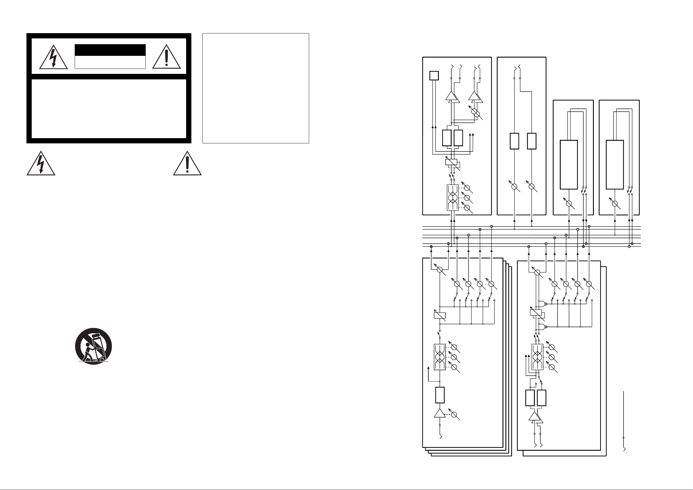
VM08
L
R
INPUT
(-10 ~ -50dBV)
INPUT
(-10 ~ -50dBV)
TRIM
METER
METER
MONO/
STEREO
CH ON
CH ON
GAIN
PAN
GAIN
PAN
POST/PRE
EFF1
EFF2
AUX1
AUX2
A/D
CH1~4
CH5/6 - 7/8
A/D
A/D
LO MID HI
100 1K 10K
ST
L R
EFF
1 2
AUX
1 2
LO MID HI
100 1K 10K
POST/PRE
EFF1
EFF2
AUX1
AUX2
FOOT SW
SCENE UP/DOWN
STEREO ON/OFF
EFF ON/OFF
STEREO MASTER
AUX MASTER
EFF1
EFF2
LO MID HI
100 1K 10K
CH ON
ST MASTER
METER
To DIGITAL OUT
SP_DIF OUT
PHONES VOL
ST BUSS OUT
(-10dBV)
PHONES OUT
(20mW)
AUX 1/2 OUT
(-10dBV)
D/A
D/A
D/A
D/A
EFFECT1
REVERB/DELAY
EFFECT2
MODULATION/DELAY
AUX 1
MASTER
AUX 2
MASTER
EFF1
MASTER
EFF2
MASTER
EFF MUTE
EFF MUTE
“WARNING”
“TO REDUCE THE RISK OF FIRE OR ELECTRIC SHOCK, DO
NOT EXPOSE THIS APPLIANCE TO RAIN OR MOISTURE.”
SAFETY INSTRUCTIONS
1. Read instructions - All the safety and operating instructions
2. Retain instructions - The safety and operating instructions
3. Heed warnings - All warnings on the appliance and in the oper-
4. Follow instructions - All operating and use instructions should
5. Water and Moisture - The appliance should not be used near
6. Carts and Stands - The appliance should be used only with a
7. Wall or Ceiling Mounting - The appliance should be mounted to
8. Ventilation - The appliance should be situated so that its lo-
CAUTION
RISK OF ELECTRIC SHOCK
DO NOT OPEN
CAUTION: TO REDUCE THE RISK OF ELECTRIC SHOCK,
DO NOT REMOVE COVER (OR BACK).
REFER SERVICING TO QUALIFIED SERVICE PERSONNEL.
should be read before the appliance is operated.
should be retained for future reference.
ating instructions should be adhered to.
be followed.
water - for example, near a bathtub, washbowl, kitchen sink,
laundry tub, in a wet basement, or near a swimming pool, and
the like.
cart or stand that is recommended by the manufacturer.
An appliance and cart combination shoumRÛbe moved with
care. Quick stops, excessive force, and uneven surfaces
may cause the appliance and cart combination to overturn.
a wall or ceiling only as recommended by the manufacturer.
cation or position does not interfere with its proper ventilation. For example, the appliance should not be situated on a
bed, sofa, rug, or similar surface that may block the ventilation openings; or, placed in a built-in installation, such as a
bookcase or cabinet that may impede the flow of air through
the ventilation openings.
NO USER-SERVICEABLE PARTS INSIDE.
The lightening flash with arrowhead symbol,
within an equilateral triangle, is intended to
alert the user to the presence of uninsulated
“dangerous voltage” within the product's enclosure that may be of sufficient magnitude to
constitute a risk of electric shock to persons.
CAUTION:
TO PREVENT ELECTRIC SHOCK, MATCH
WIDE BLADE OF PLUG TO WIDE SLOT,
FULLY INSERT.
ATTENTION:
POUR ÉVITER LES CHOCS ÉLECTRIQUES,
INTRODUIRE LA LAME LA PLUS LARGE DE
LA FICHE DANS LA BORNE CORRESPONDANTE DE LA PRISE ET POUSSER
JUSQU' AU FOND.
The exclamation point within an equilateral
triangle is intended to alert the user to the
presence of important operating and maintenance (servicing) instructions in the literature
accompanying the appliance.
9. Heat - The appliance should be situated away from heat
sources such as radiators, heat registers, stoves, or other appliances (including amplifiers) that produce heat.
10. Power Sources - The appliance should be connected to a
power supply only of the type described in the operating instructions or as marked on the appliance.
11. Grounding or Polarization - The precautions that should be
taken so that the grounding or polarization means of an appliance is not defeated.
12. Power Cord Protection - Power supply cords should be routed
so that they are not likely to be walked on or pinched by items
placed upon or against them, paying particular attention to
cords at plugs, convenience receptacles, and the point where
they exit from the appliance.
13. Cleaning - The appliance should be cleaned only as recommended by the manufacturer.
14. Nonuse Periods - The power cord of the appliance should be
unplugged from the outlet when left unused for a long period of
time.
15. Object and Liquid Entry - Care should be taken so that objects
do not fall and liquids are not spilled into the enclosure through
openings.
16. Damage requiring Service - The appliance should be serviced
by qualified service personnel when:
A. The power supply cord or the plug has been damaged;
B. Objects have fallen, or liquid has been spilled into the
C. The appliance has been exposed to rain; or
D. The appliance does not appear to operate normally or
E. The appliance has been dropped, or the enclosure damaged.
17 Servicing - The user should not attempt to service the appli-
ance beyond that described in the operating instructions. All
other servicing should be referred to qualified service personnel.
or
appliance; or
exhibits a marked changed in performance; or
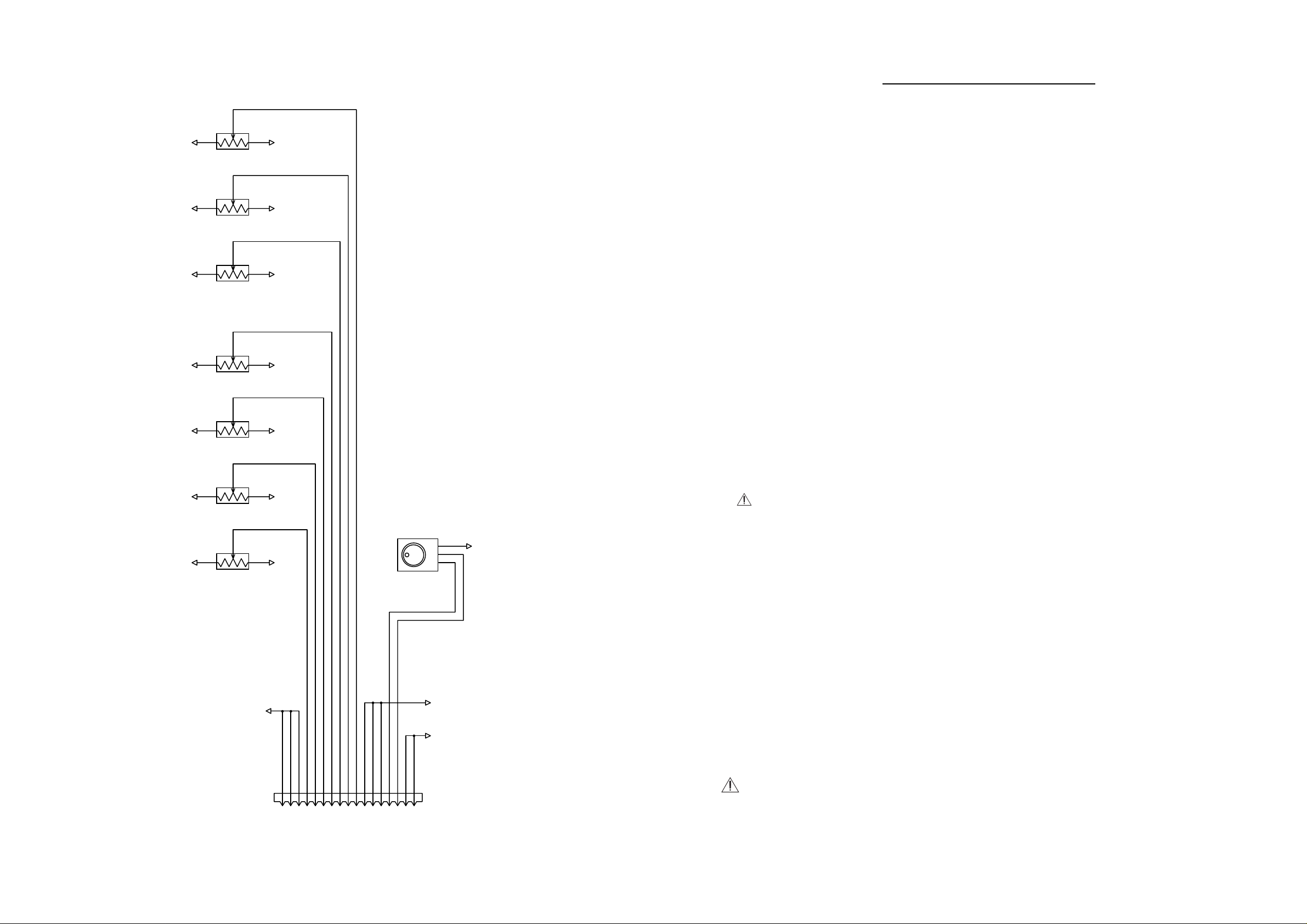
8. BLOCK DIAGRAM
31
Page 3
3
2
1
AD+5
R351
10KB
ADGND
3
2
1
AD+5
R352
10KB
ADGND
3
2
1
AD+5
R353
10KB
ADGND
3
2
1
AD+5
R354
10KB
ADGND
3
2
1
AD+5
R355
10KB
ADGND
3
2
1
AD+5
R356
10KB
ADGND
3
2
1
AD+5
R357
10KB
ADGND
1234567891011121314151617
<<<<<
<
<
AD+5
AD+5
AD+5
VR0
VR1
VR2
VR3
VR4
VR5
VR6
ADGND
ADGND
ADGND
JOG0
JOG1
DGND
DGND
AD+5
A
B
C
1
2
3
J351
FPC-17P
DGND
DGND
U351
EC12E
ADGND
VM08
VM08
TABLE OF CONTENTS
1. SPECIFICATIONS.................................................................................. 4
2. CONTROLS, INDICATORS AND CONNECTORS.......................... 5
3. SERVICE MODE ................................................................................... 6
REPLACING THE BATTERY ................................................................................ 7
4. EXPLODED VIEW ................................................................................ 8
FLAT CABLE CONNECTIONS.............................................................................. 8
5. PARTS LIST........................................................................................... 9
6. PCB PATTERN DRAWING............................................................... 11
7. CIRCUIT DIAGRAMS ........................................................................ 18
8. BLOCK DIAGRAM............................................................................. 31
NOTES
* Parts List and circuit diagrams are given in this manual to assist the service technician in maintaining
the Model VM08.
* The following accessories are supplied with VM08 as the standard accessories.
Owner's manual : 8288448000
AC adaptor AD-9B : 8270818003 (for USA/CND)
* Following is the packing material for the Model VM08.
PACK, SIDE, L, VM08 : 8228456000
: 8270818006 (for EUR)
: 8270818007 (for UK)
: 8270818010 (for JPN)
PACK, SIDE, R, VM08 : 8228457000
CARTON, INNER, VM08 : 8228732000
CARTON, OUTER, VM08 : 8228911000
FADER (1/1)
30
CAUTION
Parts marked with this sign are safety critical components. They must always be replaced with
identical components. Refer to the Fostex Parts List and ensure exact replacement.
3
Page 4
VM08
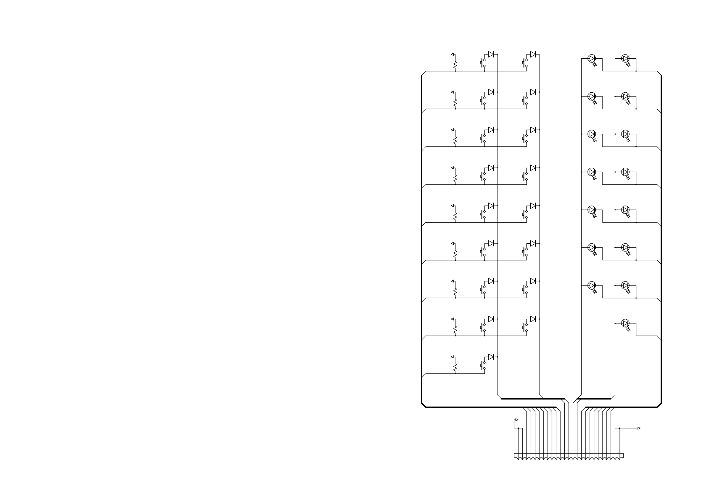
12345678910111213141516171819202122232425
DGND
DGND
CONN-M-25P
DGND
KEY0
KEY1
KEY2
KEY3
KEY4
KEY5
KEY6
KEY7
KEY8
DIG0
DIG1
LED_A0
LED_A1
LED_K0
LED_K1
LED_K2
LED_K3
LED_K4
LED_K5
LED_K6
LED_K7
J252
3
1
KEY[0..8]
DIG0
DIG1
LED_A0
LED_A1
DIG[0..1]LED_A[0..1]
D+5_1
R269
NON
S217
TACT
D209A
DAN202K
KEY8
3 2
13
D+5_1
R261
NON
S201
TACT
ENTER
S216
TACT
FADER ADJ
D201A
DAN202K
D208B
DAN202K
KEY7
3 1
23
D+5_1
R262
NON
S202
TACT
MASTER
S209
TACT
LEVEL ADJ
D201B
DAN202K
D205A
DAN202K
KEY6
3 2
13
D+5_1
R263
NON
S203
TACT
CH7/8
S210
TACT
RECALL
D202A
DAN202K
D205B
DAN202K
KEY5
3
1
23
D+5_1
R264
NON
S204
TACT
CH5/6
S211
TACT
STORE
D202B
DAN202K
D206A
DAN202K
KEY4
3
2
13
D+5_1
R265
NON
S205
TACT
CH4
S212
TACT
EFF1
D203A
DAN202K
D206B
DAN202K
KEY3
3 1
23
D+5_1
R266
NON
S206
TACT
CH3
S213
TACT
EFF2
D203B
DAN202K
D207A
DAN202K
KEY2
3 1
23
D+5_1
R268
NON
S208
TACT
CH1
S215
TACT
EFF/AUX
D204B
DAN202K
D208A
DAN202K
KEY0
3 2
13
D+5_1
R267
NON
S207
TACT
CH2
S214
TACT
PAN/EQ
D204A
DAN202K
D207B
DAN202K
KEY1
EXIT
D256
LED
D263
LED
LED_K1
CH2
PAN/EQ
D255
LED
D262
LED
LED_K2
CH3
EFF2
D254
LED
D261
LED
LED_K3
CH4
EFF1
D253
LED
D260
LED
LED_K4
CH5/6
STORE
D252
LED
D259
LED
LED_K5
CH7/8
RECALL
D251
LED
D258
LED
LED_K6
MASTER
LEVEL ADJ
D265
LED
LED_K7
FADER ADJ
D257
LED
D264
LED
LED_K0
CH1
EFF/AUX
LED_K[0..7]
4
1. SPECIFICATIONS
DEFINITION (Specification Unit : 0 dBV = 1 Vrms)
NORMAL FADER POSITION
Master fader 80 position (Master Fader display)
Input fader 80 position (Channel Fader display)
INPUT 1~4 PAN Fully CCW (L) or CW (R) position
INPUT 5/6, 7/8 PAN Center position
MIXER SECTION
INPUT 1~4
Input Level -50dBV ~ -4dBV
Input Impedance 20kΩ or more
Connector Ø6mm Mono Phone Jack/Unbalanced
INPUT 5/6, 7/8
Input Level -6dBV
Input Impedance 20kΩ or more
Connector Ø6mm TRS Phone Jack/Unbalanced
STEREO OUTPUT (L, R)
Output Level -10dBV
Load Impedance 10kΩ or more
Connector Ø6mm Mono Phone Jack/Unbalanced
AUX SEND 1/2
Output Level -10dBV
Load Impedance 10kΩ or more
Connector Ø6mm TRS Phone Jack/Unbalanced
PHONES OUT
Output Level 30mW MAX (32Ω load)
Load Impedance 16Ω or more
Connector Ø6mm TRS Phone Jack
EQUALIZER
HI (Shelving Type) ±18dB or more (10kHz)
MID (peaking type, Q=1.0) ±18dB or more (1kHz)
LO (Shelving Type) ±18dB or more (100Hz)
FREQUENCY RESPONSE
Input 1~4 (-4dBV) -> Stereo Out (-10dBV) +1, -2dB (20Hz ~ 20kHz)
Input 5~8 (-6dBV) -> Stereo Out (-10dBV) +1, -2dB (20Hz ~ 20kHz)
Input 1~4 (-50dBV) -> Stereo Out (-10dBV) +1, -3dB (20Hz ~ 20kHz)
Input 1~4 (-4dBV) -> Aux Send 1/2 (-10dBV) +1, -2dB (20Hz ~ 20kHz)
Input 5~8 (-6dBV) -> Aux Send 1/2 (-10dBV) +1, -2dB (20Hz ~ 20kHz)
Input 5~8 (-6dBV) -> Phones Out (10mW/16Ω) +1, -3dB (80Hz ~ 10kHz)
S/N (with DAT envelope filter)
Input 1~4 (+8dBV) -> Stereo Out (+2dBV) 86dB or more (IHF-A)
Input 5~8 (+6dBV) -> Stereo Out (+2dBV) 86dB or more (IHF-A)
Input 1~4 (-38dBV) -> Stereo Out (+2dBV) 75dB or more (IHF-A)
Input 1~4 (+8dBV) -> Aux Send 1/2 (+2dBV) 86dB or more (IHF-A)
Input 5~8 (+6dBV) -> Aux Send 1/2 (+2dBV) 86dB or more (IHF-A)
Phones Out Residual Noise (VR : Min) -85dBV or more (IHF-A)
DISTORTION (with DAT envelope filter)
Input 1~4 (+6dBV) -> Stereo Out (0dBV) 0.03% or less (1kHz)
Input 5~8 (+4dBV) -> Stereo Out (0dBV) 0.03% or less (1kHz)
Input 1~4 (-40dBV) -> Stereo Out (0dBV) 0.08% or less (1kHz)
Input 1~4 (+6dBV) -> Aux Send 1/2 (0dBV) 0.03% or less (1kHz)
Input 5~8 (+4dBV) -> Aux Send 1/2 (0dBV) 0.03% or less (1kHz)
Input (0dBV) -> Phones Out (20mW/16Ω) 1.0% or less (1kHz)
CROSSTALK
Input 1~4 (-4dBV) -> Aux Send 1/2 (0dBV)
(Non input channel is measured.) 60dB or more (1kHz)
CLICK NOISE
Power ON/OFF Stereo Out -20dBVp-p or less
Other switching Stereo Out -30dBVp-p or less
SHOCK NOISE -30dBVp-p or less
LEVEL INDICATION
Type LCD Bargraph Meter
Number of Indicated Levels 10dots (-48, -30, -24, -18, -12, -9, -6, -3, -1, OL)
Reference Level (-10dBV) Indication -12dB
DIGITAL SECTION
SAMPLING FREQUENCY 44.1kHz
QUANTIZATION 16 bit linear
A/D CONVERTER 20bit, 64-times Over Sampling, ∆∑
D/A CONVERTER 24bit 128-time, Over Sampling, ∆∑
S/P DIF OUT
Format IEC 60958 (S/P DIF)
Connector Optical
GENERAL
DC IN AD-9B, DC9V, 650mA (Center : Positive)
DIMENSIONS 300 (W) x 212 (D) x 70 (H) mm
WEIGHT Approx. 1.2kg
POWER SUPPLY
USA/CND 120VAC, 60Hz
EUR/UK 230VAC, 50/60Hz
JPN 100VAC, 50/60Hz
* Specifications and appearance are subject to change without notice for product improvement.
Aux Out -20dBVp-p or less
Aux Out -30dBVp-p or less
Tip:Input 5, 7 / Ring:Input 6, 8
Tip:Send 1 / Ring:Send 2
VM08
DISPLAY (2/2) : KEY & LED
29
Page 5
VM08
ST OUTR
L
PHONES
1
TRIM
2
TRIM
3
TRIM
4
TRIM
-10 -50
-10 -50
-10 -50
-10 -50
RESET
OUT
S/P DIF
DC IN
FOOT SW AUX SEND
INPUT
6/5
8/7
7
8
5
6
1
2
AD-9B
ONLY
9V
3 56421101178 9
SETUP
CLEAR
STORERECALL
SCENE
EFF SEL
EFF1 EFF2
SCENE NO.
MASTERCH
MAX
OL
1
6
12
•
•
24
•
48
-
•
MIN
L
R
EFF/AUX
EQ
E1 E2 A1 A2
PAN LO MID HI
12345678LR
PHONES
LEVEL ADJUST FADER ADJUST
PAN / EQ EFF / AUX
MAXMIN
CH PARAM EDIT
CH ON/CH SEL
MAX
MIN
MAX
MIN
MAX
MIN
MAX
MIN
MAX
MIN
MAX
MIN
EXIT ENTER
DATA
MASTER7/85/64321
8CH DIGITAL MIXER WITH
DSP EFFECT
1314 1512 16
17
18
19
20
21
22
232524
30
29
28
27
26
SEG1
SEG2
SEG3
SEG4
SEG5
SEG6
SEG7
SEG8
SEG9
SEG10
SEG11
SEG12
SEG13
SEG14
SEG15
SEG16
SEG17
SEG18
SEG19
SEG20
SEG21
SEG22
SEG23
SEG24
SEG25
SEG26
SEG27
SEG28
SEG29
SEG30
SEG31
SEG32
SEG33
SEG34
SEG35
SEG36
SEG37
SEG38
SEG39
SEG40
SEG5
SEG4
SEG3
SEG2
SEG1
COM9
COM10
COM11
COM12
COM13
COM14
COM15
COM16
SEG6
SEG7
SEG8
SEG9
SEG10
SEG16
SEG37
SEG28
SEG29
SEG40
SEG13
SEG18
SEG23
SEG28
SEG33
COM9
COM10
COM11
COM12
COM13
COM7
COM6
COM5
COM4
COM3
COM2
COM1
123456789
101112131415161718192021222324
6463626160595857565554535251504948474645444342
41
SEG22
SEG21
SEG20
SEG19
SEG18
SEG17
SEG16
SEG15
SEG14
SEG13
SEG12
SEG11
SEG10
SEG9
SEG8
SEG7
SEG6
SEG5
SEG4
SEG3
SEG2
SEG1
SEG39
SEG40
COM16
COM15
COM14
COM13
COM12
COM11
COM10
COM9
COM8
COM7
COM6
COM5
COM4
COM3
COM2
COM1
LCD_D7
LCD_D6
LCD_D5
LCD_D4
LCD_D3
LCD_D2
3
2
1
D+5_1
1
2
3
GND
2
1
DGND
D+5_1
D+5_1
DGND
D+5_1
R256
220K
R2551KR2541KR2531KR2521KR251
1K
R257
3K
J251
FPC-17P
W201
DGND
CON2
D-5
D-5
R260
5KB
25
26
27
28
29
30
31
32
33
34
35
36
37
38
39
40
80
79
78
77
76
75
74
73
72
71
70
69
68
67
66
65
SEG23
SEG24
SEG25
SEG26
SEG27
SEG28
SEG29
SEG30
SEG31
SEG32
SEG33
SEG34
SEG35
SEG36
SEG37
SEG38
RS
R/W
E
LCD_D0
LCD_D1
C280
0.01
SEG22
SEG21
SEG20
SEG19
SEG18
SEG17
SEG16
SEG15
SEG14
SEG13
SEG12
SEG11
SEG10
SEG9
SEG8
SEG7
SEG6
SEG5
SEG4
SEG3
SEG2
SEG1
GND
OSCI
SEG39
SEG40
COM16
COM15
COM14
COM13
COM12
COM11
COM10
COM9
COM8
COM7
COM6
COM5
COM4
COM3
COM2
COM1
DB7
DB6
DB5
DB4
DB3
DB2
SEG23
SEG24
SEG25
SEG26
SEG27
SEG28
SEG29
SEG30
SEG31
SEG32
SEG33
SEG34
SEG35
SEG36
SEG37
SEG38
OSCO
V1
V2
V3
V4
V5
CL1
CL2
VCC
M
D
RS
R/W
E
DB0
DB1
U250
HD44780U
U251
LCD_FD4
1234567891011121314151617
>>>>>>>>>>>
DGND
LCD_D0
LCD_D1
LCD_D2
LCD_D3
LCD_D4
LCD_D5
LCD_D6
LCD_D7ER/WRSD+5
D+5
D+9
DGND
D-5
SEG[1..40]
L202
LAMP
DGND
COM[1..16]
SEG1
SEG2
SEG3
SEG4
SEG5
SEG6
SEG7
SEG8
SEG9
SEG10
SEG11
SEG12
SEG13
SEG14
SEG15
SEG16
SEG17
SEG18
SEG19
SEG20
SEG21
SEG22
SEG23
SEG24
SEG25
SEG26
SEG27
SEG28
SEG29
SEG30
SEG31
SEG32
SEG33
SEG34
SEG35
SEG36
SEG37
SEG38
SEG39
SEG40
1
2
3
4
5
6
7
8
9
10
11
12
13
14
15
16
17
18
19
20
21
22
23
24
25
26
27
28
29
30
31
32
33
34
35
36
37
38
39
40
41
42
43
44
45
46
47
48
49
50
51
52
53
54
55
56
57
58
59
60
61
62
63
64
65
66
67
68
69
70
71
72
73
74
75
76
77
78
79
80
D+9
D+5_2
D+5_2
DGND
D+5_2
D+5_2
R270
NON
R271
0
R272
NON
R273
NON
C283
0.1
C282
0.1
C281
0.1
U252
L78M05T-TL
L201
LAMP
SEG5
SEG4
SEG3
SEG2
SEG1
COM9
COM10
COM11
COM12
COM13
COM14
COM15
COM16
SEG6
SEG7
SEG8
SEG9
SEG10
SEG16
SEG37
SEG28
SEG29
SEG40
SEG13
SEG18
SEG23
SEG28
SEG33
COM9
COM10
COM11
COM12
COM13
COM7
COM6
COM5
COM4
COM3
COM2
COM1
AGND_1DGND
D+9
Vin Vout
U252 R273 R272
R271 R270
D+5_2
D+5_1
D+9
KEY&LED
D+5_1
VM08
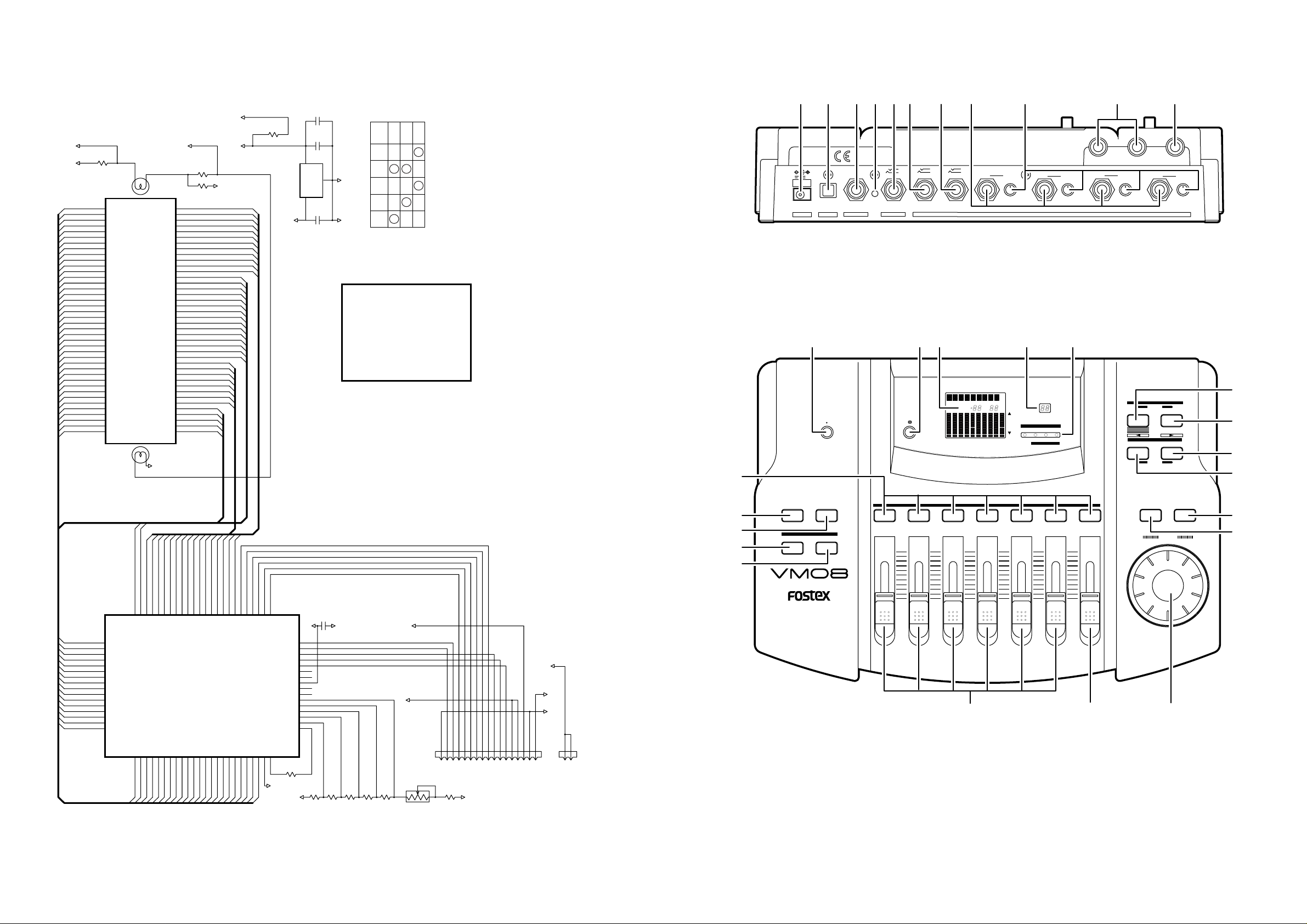
2. CONTROLS, INDICATORS AND CONNECTORS
1. DC INLET connector (Center : Positive)
2. S/P DIF optical output connector [Optical]
3. FOOT SW jack [Ø6 mm Phone] (unlatched)
4. RESET switch
5. AUX SEND jack [Ø6 mm TRS Phone]
6. INPUT 7/8 jack [Ø6 mm TRS Phone]
7. INPUT 5/6 jack [Ø6 mm TRS Phone]
8. INPUT 1/2/3/4 jacks [Ø6 mm Phone]
9. TRIM knobs 1/2/3/4
10. Stereo OUTPUT L/R jacks [Ø6 mm Phone]
11. Headphone jack [Ø6 mm TRS Phone]
DISPLAY (1/2) : LCD
28
12. Headphone volume control knob
13. Contrast adjusting knob
14. LCD display
15. SCENE Number display
16. Status indicator
17. SCENE RECALL key
18. SCENE STORE key
19. EFFECT 2 Select key
20. EFFECT 1 Select key
21. ENTER key
22. EXIT key
23. DATA encoder
24. INPUT faders
25. MASTER fader
26. CHANNEL ON/SELECT keys
27. LEVEL ADJUST key
28. FADER ADJUST key
29. PAN/EQ select key
30. EFF/AUX select key
5
Page 6

VM08
2
1 3
243
1
243
1
6
5
7
2
13
2
13
3
2
84
1
2
13
5
6
7
243
1
3
2
1
5
4
1
1234567
8
C32 5
0.01
2
3
84
1
1
2
J451
CONN-M-8
A+5
STEREO_OUT_L+
STEREO_OUT_L-
STEREO_OUT_R
STEREO_OUT_R-
MUTE
A-5
AGND
W301
CON2
to DISPLAY
A+5_1
AGND
R330
10K
R331
8.2K
C330
0.01
C331
100/10
A+5_1
VBIAS
C311
47/16
R311
3.6K
R312
3.6K
R313
2.4K
R413
2.4K
R415
200
R315
200
C315
820P
C415
820P
C327
NON
C427
NON
AGND
AGND
AGND
AGND
A-5
A+5
AGND
AGND
AGND
AGND
R510A
RK09K12C
AGND
AGND
AGND
AGND
AGND
DGND
AGND
DGND
D+5_1
VBIAS
R319
1K
R320
100K
R321
470
R421
470
U410A
NJM3414
U410B
NJM3414
R420
100K
R419
1K
VBIAS
AGND
AGND
AGND
R510B
RK09K12C
R418
1K
R318
1K
C319
10/16
C320
100/10
C420
100/10
C419
10/16
C421
NON
C423
220/10
R423
10
R323
10
R324
10K
R424
10K
C323
220/10
L413
BEAD
L414
BEAD
C321
NON
C322
10P
R322
4.7K
C324
100/10
R422
4.7K
C422
10P
U413
DTC314TK
U414
DTC314TK
R411
3.6K
C413
0.0068
C414
0.0068
R314
200
R316
2.4K
C316
820P
R414
200
R416
2.4K
C416
820P
C318
0.01
C317
10/16
R317
1K
L411
BEAD
J411
YKB21-5074
J412
YKB21-5074
U411
DTC314TK
U412
DTC314TK
L412
BEAD
AGND
AGND
AGND
AGND
R417
1K
C417
10/16
U210A
NJM4565M
U210B
NJM4565M
C313
0.0068
C314
0.0068
R412
3.6K
C312
47/16
C411
47/16
C412
47/16
MASTR L
(-10dBV)
MASTR R
(-10dBV)
J413
YKB21-5074
PHONES
AGND
C328
0.01
3. SERVICE MODE
3-1 Software Version Check
While holding down both the PAN/EQ and EFF/AUX keys, press the EFF 1 key.
• The LCD Display will show the Software Version of the VM08 for about a second,
and then return to the Normal mode display.
VM08
MASTERCH
6
3-2 Battery Check
While holding down both the PAN/EQ and EFF/AUX keys, press the EFF 2 key.
• The LCD Display will show the voltage of the memory backup battery inside the
VM08 for about a second, and then return to the Normal mode display.
• If the voltage falls below 2.2V , the message “BattEmpty” will appear when powering ON.
• If the message “BattEmpty” is displayed, please replace the battery with the new
one. For exchanging procedure, please refer to page 7.
3-3 Display Check
While holding down both the PAN/EQ and EFF/AUX keys, press the
EXIT key.
• All the LEDs and LCD segments are supposed to start blinking.
Check if they are correctly blinking or not.
• Pressing the ENTER key will change the blinking pattern.
• Pressing the EXIT key will put the VM08 in the condition right
3-4 Fader Check
after powering on.
While holding down both the PAN/EQ and EFF/AUX keys,
press the FADER ADJUST key.
• Confirm that 1~4 channel parameter value (00~99) and the
DATA encoder parameter value (0~9) correctly appears on
the Character Display.
• Confirm that 5/6 channel parameter value (00~99) correctly
appears on the CH FADER Display.
• Confirm that 7/8 channel parameter value (00~99) correctly appears on the MASTER FADER Display.
• Confirm that Master Fader parameter value (00~99) correctly appears on the SCENE NO. Display.
• If the EXIT key is pressed, the VM08 returns to Normal mode display.
3-5 Key Check
While holding down both the PAN/EQ and EFF/AUX keys, press the LEVEL ADJUST key.
• Confirm that the name of the switch you press appears on the Character Display.
• If two or more switches are pressed at the same time, "NG" prompt will be displayed on the Character Display.
• If DATA encoder is rotated, the VM08 returns to Normal mode display.
3-6 Test Scene RECALL
While holding down both the PAN/EQ and EFF/AUX keys, press the SCENE RECALL key
• This mode is designed to use at our manufacturer exclusively. It has nothing to do with servicing the unit.
PHONES
Blink
MAXMIN
LEVEL ADJUST FADER ADJUST
CH PARAM EDIT
PAN / EQ EFF / AUX
8CH DIGITAL MIXER WITH
DSP EFFECT
2ch1ch 4ch
3ch
5/6ch 7/8ch MASTER
1
MAX
MIN
2
MAX
MIN
MASTERCH
OL
1
•
6
•
12
•
24
•
48
-
12345678LR
CH ON/CH SEL
3
MAX
MAX
MIN
MIN
DATA
encoder
MAX
R
E1 E2 A1 A2
L
MIN
PAN LO M ID HI
MAX
EFF/AUX
R
SCENE NO.
EQ
MAX
MIN
MASTER7/85/64
MAX
MIN
SCENE NO.
MASTERCH
SCENE
CLEAR
EFF SEL
EFF1 EFF1
SETUP
EXIT ENTER
STORERECALL
DATA
ANALOG OUT (1/1)
27
Page 7

VM08
2
13
243
1
6
5
7
2
13
AUX_SEND_AL-
AUX_SEND_AL+
AUX_SEND_BL-
AUX_SEND_BL+
AUX_SEND_AR-
AUX_SEND_AR+
AUX_SEND_BR-
AUX_SEND_BR+
AUX_SEND_AR-
AUX_SEND_AR+
AUX_SEND_BR-
AUX_SEND_BR+
AUX_SEND_AL-
AUX_SEND_AL+
AUX_SEND_BL-
AUX_SEND_BL+
2
3
84
1
R111
3.6K
C111
47/16
C113
0.0068
C121
NON
U110A
NJM4565M
U110B
NJM4565M
C116
820P
C115
820P
C117
22/16
R120
1K
U111
DTC314TK
L111
BEAD
R119
100K
C118
0.01
C119
0.01
C114
0.0068
AGND
AGND
AGND
AGND
AGND
C217
22/16
R220
1K
R219
100K
AGND
AGND
AGND
U211
DTC314TK
L211
BEAD
AGND
J111
YKB21-5074
AGND
A-5
A+5
AGND
C112
47/16
C211
47/16
C212
47/16
R113
3.6K
R115
2.4K
C213
0.0068
C214
0.0068
AGND
R215
2.4K
R117
220
R116
220
C221
NON
C216
820P
R217
220
R216
220
R118
2.4K
C215
820P
R218
2.4K
R114
3.6K
R112
3.6K
R211
3.6K
R213
3.6K
R214
3.6K
R212
3.6K
AUX SEND
(-10dBV)
AGND
MUTE
MUTE
3-7 Memory Clear
While holding down both the PAN/EQ and EFF/AUX keys, press the SCENE STORE key
• Pressing the ENTER key would clear the memory and the message
“ClearMem!”appears. All the setup will be initialized.
• Pressing the key other than ENTER returns to the Normal Mix mode display (The
Scene No. 00 is displayed.) and the memory will not be initialized.
• Pressing the RESET SW would also clear the memory and the message “ClearMem!”
appears.
Gain Table
The value appears in the LCD display corresponds to the gain in dB as shown below.
INPUT Fader
MASTER Fader
EFFECT Send
Value Gain (dB)
00 -
01 -72.0
05 -55.0
10 -42.5
15 -35.0
20 -28.75
25 -23.0
30 -18.0
35 -15.5
40 -13.0
45 -10.5
50 -8.5
55 -7.0
60 -5.5
65 -4.0
70 -2.5
75 -1.25
80 0
85 +1.5
90 +3.0
95 +4.67
99 +6.0
∞
INPUT 1~4 PAN
Value Gain (dB)
Left Right
L10 0.0
L9 -0.1 -32.0
L8 -0.25 -23.5
L7 -0.4 -17.6
L6 -0.7 -14.1
L5 -1.0 -11.3
L4 -1.4 -9.0
L3 -1.8 -7.1
L2 -2.2 -5.5
L1 -2.6 -4.2
C -3.0 -3.0
R1 -4.2 -2.6
R2 -5.5 -2.2
R3 -7.1 -1.8
R4 -9.0 -1.4
R5 -11.3 -1.0
R6 -14.1 -0.7
R7 -17.6 -0.4
R8 -23.5 -0.25
R9 -32.0 -0.1
R10
-
∞
-
0.0
Value Gain (dB)
∞
L10 0
L9 0 -36
L8 0 -26
L7 0 -18
L6 0 -12
L5 0 -8
L4 0 -5
L3 0 -3
L2 0 -1.5
L1 0 -0.5
C00
R1 -0.5 0
R2 -1.5 0
R3 -3 0
R4 -5 0
R5 -8 0
R6 -12 0
R7 -18 0
R8 -26 0
R9 -36 0
R10
REPLACING THE BATTERY
If the voltage of the internal memory backup battery falls below
2.2V, the message “BattEmpty” will appear when powering ON.
CAUTION
• Replacing the battery with the new one would basically
initialize the backup data.
• In order to retain the backup data, please replace the battery while powering on.
Part No. : 8239120000
BATTERY, 3V, CR2032
MAIN PCB
INPUT 5/6, 7/8
BAL
MASTER BAL
Left Right
-
∞
VM08
MASTER
MASTER
-
∞
0
MAIN (9/9) : AUX SEND
26
7
Page 8

VM08
3
2
84
1
AGN D
6
5
7
5423781
INPUT5/6
(-10dBV)
J501
YKB21-5006
AGND
AGND
AGND
AGND AGND
A+5
1/2VCC
L501
BEAD
R501
62K
C501
10/16
C503
NON
C505
NON
R507
NON
R505
10K
R506
10K
C504
0.01
R504
0
C502
NON
C506
10/16
R502
47K
R508
1K
R503
100K
U501A
JM2115M
U501B
JM2115M
AIN5+
AIN5-
3
2
84
1
AGN D
6
5
7
AGND
AGND
AGND AGND
A+5
1/2VCC
L601
BEAD
R601
62K
C601
10/16
C603
NON
C605
NON
R607
NON
R605
10K
R606
10K
C604
0.01
R604
0
C602
NON
C606
10/16
R602
47K
R608
1K
R603
100K
U601A
JM2115M
U601B
JM2115M
AIN6+
AIN6-
3
2
84
1
AGN D
6
5
7
5423781
INPUT7/8
(-10dBV)
J601
YKB21-5006
AGND
AGND
AGND
AGND AGND
A+5
1/2VCC
L701
BEAD
R701
56K
C701
10/16
C703
NON
C705
NON
R707
NON
R705
10K
R706
10K
C704
0.01
R704
0
C702
NON
C706
10/16
R702
24K
R708
1K
R703
100K
U701A
JM2115M
U701B
JM2115M
AIN7+
AIN7-
3
2
84
1
AGN D
6
5
7
AGND
AGND
AGND AGND
A+5
1/2VCC
L801
BEAD
R801
56K
C801
10/16
C803
NON
C805
NON
R807
NON
R805
10K
R806
10K
C804
0.01
R804
0
C802
NON
C806
10/16
R802
24K
R808
1K
R803
100K
U801A
JM2115M
U801B
JM2115M
AIN8+
AIN8-
4. EXPLODED VIEW
VM08
11
1
BBT 3X8 BZn
18
13
16
BBT
3X8 BZn
17
BBT
3X8 BZn
2
6
7
3
5
BBT 3X8 BZn
4
B 3X5
BZn
14
BBT
3X8 BZn
15
8
9
10
12
11
19
No. Part No. Description
1 8212664000 PANEL, TOP, VM08
2 8226239001 KNOB, FADER, N4.5
3 8212665000 WINDOW, LCD, VM08
4 8226238000 KNOB, JOG, FD-4/VM08
5 8274229000 PCB ASSY, FADER, VM08
6 8221301000 BRACKET, PHONES, VM08
7 8216731000 SHIELD, PHONES, VM08
8 8204082000 PLATE, MOUNTING, B
9 8274230000 PCB ASSY, PHONES, VM08
10 8274228000 PCB ASSY, DISPLAY, VM08
11 8226246001 BUTTON, 7X13, LED
12 8226246002 BUTTON, 7X13, N4.5
13 8221299000 SHIELD, MAIN, VM08
14 8274227000 PCB ASSY , MAIN, VM08
15 8216714000 SHIELD, EMI, VM08
16 8239120000 BATTERY, 3V, CR2032
17 8216699000 SHEET, BATTERY, VM04/VM08
18 8270818003 AC ADAPTOR, AD-9B/USA, CSA
19 8216723000 SHEET, ISOLATION, VM08
20 8207012000 FOOT, FF-822
21 8221300000 PANEL, BOTTOM, VM08
8270818006 AC ADAPT OR, AD-9B/EUR
8270818007 AC ADAPT OR, AD-9B/UK
8270818010 AC ADAPT OR, AD-9B/JPN
BBT 3X8 BZn
20
BBT
21
3X8 BZn
3X8 BZn
BBT
* Flat Cable Connections
A, MAIN PCB : J2 <-> DISPLAY PCB : J251
CABLE, FLAT, FFC, 17P, L150 (P/N 8276839615)
B, MAIN PCB : J3 <-> FADER PCB : J351
CABLE, FLAT, FFC, 17P, L200 (P/N 8276839620)
C, MAIN PCB : J5 <-> DISPLAY PCB : J252
CABLE, FLAT, FFC, 25P, L150 (P/N 8276840415)
D, MAIN PCB : J6 <-> PHONES PCB : J351
CABLE, FLAT, FFC, 8P, L150 (P/N 8276838715)
MAIN (8/9) : ANALOG IN 2
8
25
Page 9

VM08
C203
2
3
84
1
243
1
J101
YKB21-5074
AGND
AGND
AGND
L101
BEAD
C101
10/16
C105
100/10
R107
100K
R104
82
R109
0
1/2VCC
R110
20KC
C102
NON
C103
100P
U102B
NJM2068M
R103
1M
C107
10/16
C120
NON
C122
NON
C106
NON
C108
0.01
R108
56K
R105
10K
R106
10K
R101
15K
A+5
AGND
AGND
AGND
U101A
NJM2115
U101B
NJM2115
C123
10/16
R102
20K
6
5
7
5
6
7
3
2
1
2
3
84
1
INPUT1
(-10dBV ~ -50dBV)
AIN1-
AIN1+
243
1
J201
YKB21-5074
AGND
AGND
AGND
L201
BEAD
C201
10/16
C205
100/10
R207
100K
R204
82
R209
0
1/2VCC
R210
20KC
C202
NON
A+5
AGND
AGND
A-5
C203
100P
C108
0.01
C109
0.01
U102A
NJM2068M
R203
1M
C207
10/16
C220
NON
C222
NON
C206
NON
C204
0.01
R208
56K
R205
10K
R206
10K
R201
15K
A+5
AGND
AGND
AGND
U201A
NJM2115
U201B
NJM2115
C223
10/16
R202
20K
6
5
7
3
2
1
48
3
2
1
2
3
84
1
INPUT2
(-10dBV ~ -50dBV)
AIN2-
AIN2+
243
1
J301
YKB21-5074
AGND
AGND
AGND
L301
BEAD
C301
10/16
C305
100/10
R307
100K
R304
82
R309
0
1/2VCC
R310
20KC
C302
NON
C303
100P
U202B
NJM2068M
R303
1M
C307
10/16
C120
NON
C322
NON
C306
NON
C308
0.01
R308
56K
R305
10K
R306
10K
R301
15K
A+5
AGND
AGND
AGND
U301A
NJM2115
U301B
NJM2115
C323
10/16
R302
20K
6
5
7
5
6
7
3
2
1
2
3
84
1
INPUT3
(-10dBV ~ -50dBV)
AIN3-
AIN3+
243
1
J401
YKB21-5074
AGND
AGND
AGND
L401
BEAD
C401
10/16
C405
100/10
R407
100K
R404
82
R409
0
1/2VCC
R410
20KC
C402
NON
A+5
AGND
AGND
A-5
C403
100P
C308
0.01
C309
0.01
U202A
NJM2068M
R403
1M
C407
10/16
C220
NON
C422
NON
C406
NON
C404
0.01
R408
56K
R405
10K
R406
10K
R401
15K
A+5
AGND
AGND
AGND
U401A
NJM2115
U401B
NJM2115
C423
10/16
R402
20K
6
5
7
3
2
1
48
3
2
1
2
3
84
1
INPUT4
(-10dBV ~ -50dBV)
AIN4-
AIN4+
A+5
R38
10K
C51
100/10
C50
220/10
1/2VCC
C32
0.01
C34
47/10
C55
NON
C33
0.01
C31
0.01
C30
0.01
R39
10K
AGND
AGND
A+5
U40A
NJM2115
D-5
AGND
A-5
L4
220µH
24
MAIN (7/9) : ANALOG IN 1
VM08
5. PARTS LIST
8274227000 PCB ASSY , MAIN, VM08
ICs
Ref. No. Part No. Description
U001 8236541300 IC, ST, AN, DC-DC, NJM2360AM
U002 8236545014 IC, ST, TSSOP, 74VHC14
U003 8236502500 IC, ST, AN, RESET, NJM2103M
U004 8236086201 IC, QFP, DG, CPU, VM08, MN101C28DFA
U005 8236046701 IC, 220, AN, REGULATOR, TA78DM05S
U006 8236570801 IC, ST, DG, DRIVER, DTB114TK
U007, 008 8236570101 IC, ST, DG, DRIVER, DTC114EK
U009 8236545086 IC, ST, TSSOP, 74VHC86
U010 8236504900 IC, ST, DG, DIGITALOUT, TC9271F
U011 8236540301 IC, ST, AN, REGULATOR, L78M05T-TL
U020 8236541700 IC, ST, DG, ADDA, AK4522
U021~024 8236545000 IC, ST, TSSOP, 74VHC00
U025 8236545010 IC, ST, TSSOP, 74VHC10
U026 8236086100 IC, QFP, DG, DSP, AK7716
U030 8236086100 IC, QFP, DG, DSP, AK7716
U031 8236086100 IC, QFP, DG, DSP, AK7716
U032 8236084600 IC, TSOP, DG, SRAM, TC551001CFT-70L
U040 8236505011 IC, ST, AN, OPAMP, NJM2115M(TEI)
U101~801 8236505011 IC, ST, AN, OPAMP, NJM2115M(TEI)
U102, 202 8236540500 IC, ST, AN, NJM2068MD(TEI)
U110 8236541200 IC, ST, AN, OPAMP, NJM4565M
U111 8236570201 IC, ST, DG, DRIVER, DTC314TK
U212 8236570201 IC, ST, DG, DRIVER, DTC314TK
TRANSISTORs
Ref. No. Part No. Description
Q001, 002 8234100802 TR, VT, PNP, 2SA1150Y
DIODEs
Ref. No. Part No. Description
D001, 002 8234019612 D, VT, DSK10C-ET1
D003 8234108400 D, VT, SCHOTTKEY, EK03W
D004 8234019612 D, VT, DSK10C-ET1
D005 8234502100 D, ST, SCHOTTKY, SB05-05CP
D006, 007 8234502800 D, ST, DAN202K
D008 8234019612 D, VT, DSK10C-ET1
D009~011 8234502800 D, ST, DAN202K
RESISTORs
Ref. No. Part No. Description
R001~003 8230510473 RES, ST, CARBON, 1/15W, 47K, 5%
R004 8230510104 RES, ST, CARBON, 1/15W, 100K, 5%
R005 8230500109 RES, ST, CARBON, 1/10W, 1, 5%
R006 8230510102 RES, ST, CARBON, 1/15W, 1K, 5%
R007 8230510302 RES, ST, CARBON, 1/15W, 3K, 5%
R008~015 8230510750 RES, ST, CARBON, 1/15W, 75, 5%
R016~019 8230510101 RES, ST, CARBON, 1/15W, 100, 5%
R020 8230510102 RES, ST, CARBON, 1/15W, 1K, 5%
R021~025 8230510103 RES, ST, CARBON, 1/15W, 10K, 5%
R026~028 non
R029 8230510103 RES, ST, CARBON, 1/15W, 10K, 5%
R030 8230510103 RES, ST, CARBON, 1/15W, 10K, 5%
R032 8230510103 RES, ST, CARBON, 1/15W, 10K, 5%
R033, 034 8230510102 RES, ST, CARBON, 1/15W, 1K, 5%
R035 8230510222 RES, ST, CARBON, 1/15W, 2.2K, 5%
R036 8230510124 RES, ST, CARBON, 1/15W, 120K, 5%
R037 8230510000 RES, ST, CARBON, 1/15W, 0, 5%
R038, 039 8230510103 RES, ST, CARBON, 1/15W, 10K, 5%
R040~049 8230510473 RES, ST, CARBON, 1/15W, 47K, 5%
R050~053 8230510473 RES, ST, CARBON, 1/15W, 47K, 5%
R054 8242505102 FILTER, ST, EMI, EXC3BB, 102
R055~059 8230510473 RES, ST, CARBON, 1/15W, 47K, 5%
R060~063 8230510331 RES, ST, CARBON, 1/15W, 330, 5%
R072 8230510101 RES, ST, CARBON, 1/15W, 100, 5%
R073 8230510100 RES, ST, CARBON, 1/15W, 10, 5%
R074~080 8230510101 RES, ST, CARBON, 1/15W, 100, 5%
R081 8230510100 RES, ST, CARBON, 1/15W, 10, 5%
R101~401 8230510153 RES, ST, CARBON, 1/15W, 15K, 5%
R102~402 8230510203 RES, ST, CARBON, 1/15W, 20K, 5%
R103~403 8230510105 RES, ST, CARBON, 1/15W, 1M, 5%
R104~404 8230510820 RES, ST, CARBON, 1/15W, 82, 5%
R105~405 8230510103 RES, ST, CARBON, 1/15W, 10K, 5%
R106~406 8230510103 RES, ST, CARBON, 1/15W, 10K, 5%
R107~407 8230510104 RES, ST, CARBON, 1/15W, 100K, 5%
R108~408 8230510563 RES, ST, CARBON, 1/15W, 56K, 5%
R109~409 8230510000 RES, ST, CARBON, 1/15W, 0, 5%
R110~410 8240293003 POT, PL, RT9, 20KC, EVU
R111, 211 8230510362 RES, ST, CARBON, 1/15W, 3.6K, 5%
R112, 212 8230510362 RES, ST, CARBON, 1/15W, 3.6K, 5%
R113, 213 8230510362 RES, ST, CARBON, 1/15W, 3.6K, 5%
R114, 214 8230510362 RES, ST, CARBON, 1/15W, 3.6K, 5%
R115, 215 8230510242 RES, ST, CARBON, 1/15W, 2.4K, 5%
R116, 216 8230510221 RES, ST, CARBON, 1/15W, 220, 5%
R117, 217 8230510221 RES, ST, CARBON, 1/15W, 220, 5%
R118, 218 8230510242 RES, ST, CARBON, 1/15W, 2.4K, 5%
R119, 219 8230510104 RES, ST, CARBON, 1/15W, 100K, 5%
R120, 220 8230510102 RES, ST, CARBON, 1/15W, 1K, 5%
R150~156 8230510101 RES, ST, CARBON, 1/15W, 100, 5%
R157~160 8230510331 RES, ST, CARBON, 1/15W, 330, 5%
Ref. No. Part No. Description
R161 8230510100 RES, ST, CARBON, 1/15W, 10, 5%
R170 8230510100 RES, ST, CARBON, 1/15W, 10, 5%
R171~175 8230510101 RES, ST, CARBON, 1/15W, 100, 5%
R176~179 8230510331 RES, ST, CARBON, 1/15W, 330, 5%
R190 8230510100 RES, ST, CARBON, 1/15W, 10, 5%
R191~193 8230510101 RES, ST, CARBON, 1/15W, 100, 5%
R194~197 8230510331 RES, ST, CARBON, 1/15W, 330, 5%
R501, 601 8230510623 RES, ST, CARBON, 1/15W, 62K, 5%
R701, 801 8230510563 RES, ST, CARBON, 1/15W, 56K, 5%
R502, 602 8230510473 RES, ST, CARBON, 1/15W, 47K, 5%
R702, 802 8230510243 RES, ST, CARBON, 1/15W, 24K, 5%
R503~803 8230510104 RES, ST, CARBON, 1/15W, 100K, 5%
R504~804 8230510000 RES, ST, CARBON, 1/15W, 0, 5%
R505~805 8230510103 RES, ST, CARBON, 1/15W, 10K, 5%
R506~806 8230510103 RES, ST, CARBON, 1/15W, 10K, 5%
R507~807 non
R508~808 8230510102 RES, ST, CARBON, 1/15W, 1K, 5%
Ref. No. Part No. Description
C001, 002 8233515104 CAP, ST, CER, 25V, 0.1µF, +80, CC11F
C003, 004 8233512300 CAP, ST, CER, 50V, 30pF, 5%, CC11SL
C005, 006 8233515104 CAP, ST, CER, 25V, 0.1µF, +80, CC11F
C007~010 8233513103 CAP, ST, CER, 50V, 0.01µF, 15%, CC11R
C011 8233513471 CAP, ST, CER, 50V, 470pF, 15%, CC11R
C012 8232143477 CAP, VT, ALU, 16V, 470µF, 20%, SME-VB
C013~016 8232142107 CAP, VT, ALU, 10V, 100µF, 20%, SME-VB
C017 8232363127 CAP, VT, ALU, 6.3V, 120µF, 20%, LXV, DS
C018, 019 8232143106 CAP, VT, ALU, 16V, 10µF, 20%, SME-VB
C020 8232146105 CAP, VT, ALU, 50V, 1µF, 20%, SME-VB
C021 8232143107 CAP, VT, ALU, 16V, 100µF, 20%, SME-VB
C022~028 8233513103 CAP, ST, CER, 50V, 0.01µF, 15%, CC11R
C029 8232142107 CAP, VT, ALU, 10V, 100µF, 20%, SME-VB
C030~033 8233513103 CAP, ST, CER, 50V, 0.01µF, 15%, CC11R
C034 8232142476 CAP, VT, ALU, 10V, 47µF, 20%, SME-VB
C035, 036 8233513103 CAP, ST, CER, 50V, 0.01µF, 15%, CC11R
C037 8232143106 CAP, VT, ALU, 16V, 10µF, 20%, SME-VB
C040, 041 non
C043 non
C050 8232142227 CAP, VT, ALU, 10V, 220µF, 20%, SME-VB
C051, 052 8232142107 CAP, VT, ALU, 10V, 100µF, 20%, SME-VB
C053 8232142477 CAP, VT, ALU, 10V, 470µF, 20%, SME-VB
C054, 055 non
C060, 061 8233513152 CAP, ST, CER, 50V, .0015µF, 15%, CC11R
C070 8233513103 CAP, ST, CER, 50V, 0.01µF, 15%, CC11R
C076, 077 8233513103 CAP, ST, CER, 50V, 0.01µF, 15%, CC11R
C081 8233513103 CAP, ST, CER, 50V, 0.01µF, 15%, CC11R
C083~086 8232143106 CAP, VT, ALU, 16V, 10µF, 20%, SME-VB
C090~095 8233513103 CAP, ST, CER, 50V, 0.01µF, 15%, CC11R
C101~401 8232143106 CAP, VT, ALU, 16V, 10µF, 20%, SME-VB
C102~402 non
C103~403 8233513101 CAP, ST, CER, 50V, 100pF, 15%, CC11R
C104~404 8233513103 CAP, ST, CER, 50V, 0.01µF, 15%, CC11R
C105~405 8232142107 CAP, VT, ALU, 10V, 100µF, 20%, SME-VB
C106~406 non
C107~407 8232143106 CAP, VT, ALU, 16V, 10µF, 20%, SME-VB
C108 8233513103 CAP, ST, CER, 50V, 0.01µF, 15%, CC11R
C109 8233513103 CAP, ST, CER, 50V, 0.01µF, 15%, CC11R
C111, 211 8232143476 CAP, VT, ALU, 16V, 47µF, 20%, SME-VB
C112, 212 8232143476 CAP, VT, ALU, 16V, 47µF, 20%, SME-VB
C113, 213 8233513682 CAP, ST, CER, 50V, 0.0068µF, 15%, CC11R
C114, 214 8233513682 CAP, ST, CER, 50V, 0.0068µF, 15%, CC11R
C115, 215 8233513821 CAP, ST, CER, 50V, 820pF, 15%, CC11R
C116, 216 8233513821 CAP, ST, CER, 50V, 820pF, 15%, CC11R
C117, 217 8232143226 CAP, VT, ALU, 16V, 22µF, 20%, SME-VB
C118 8233513103 CAP, ST, CER, 50V, 0.01µF, 15%, CC11R
C119 8233513103 CAP, ST, CER, 50V, 0.01µF, 15%, CC11R
C120~420 non
C121~421 non
C122~422 non
C123~423 8232143106 CAP, VT, ALU, 16V, 10µF, 20%, SME-VB
C150~154 8233515104 CAP, ST, CER, 25V, 0.1µF, +80, CC11F
C155, 156 8233512220 CAP, ST, CER, 50V, 22pF, 5%, CC11SL
C157~163 8233513103 CAP, ST, CER, 50V, 0.01µF, 15%, CC11R
C167~170 8232143106 CAP, VT, ALU, 16V, 10µF, 20%, SME-VB
C172, 173 8233513152 CAP, ST, CER, 50V, .0015µF, 15%, CC11R
C180~184 8233515104 CAP, ST, CER, 25V, 0.1µF, +80, CC11F
C185~191 8233513103 CAP, ST, CER, 50V, 0.01µF, 15%, CC11R
C192~195 8232143106 CAP, VT, ALU, 16V, 10µF, 20%, SME-VB
C197, 198 8233513152 CAP, ST, CER, 50V, .0015µF, 15%, CC11R
C250~254 8233515104 CAP, ST, CER, 25V, 0.1µF, +80, CC11F
C255~261 8233513103 CAP, ST, CER, 50V, 0.01µF, 15%, CC11R
C262~266 8232143106 CAP, VT, ALU, 16V, 10µF, 20%, SME-VB
C268, 269 8233513152 CAP, ST, CER, 50V, .0015µF, 15%, CC11R
C270 8233513103 CAP, ST, CER, 50V, 0.01µF, 15%, CC11R
C308, 309 8233513103 CAP, ST, CER, 50V, 0.01µF, 15%, CC11R
C501~801 8232143106 CAP, VT, ALU, 16V, 10µF, 20%, SME-VB
C502~802 non
C503~803 non
C504~804 8233513103 CAP, ST, CER, 50V, 0.01µF, 15%, CC11R
C505~805 non
C506~806 8232143106 CAP, VT, ALU, 16V, 10µF, 20%, SME-VB
RESISTORs
CAPACITORs
ALU = Electrolytic
CER = Ceramic type
9
Page 10

[ANA]
[ANA]
[ANA]
[ANA]
AIN6-
AIN6+
AIN5-
AIN5+
AIN6-
AIN6+
AIN5-
AIN5+
123456789
101112131415161718192021222324
25
TESTI1
/INIT_RESET
/CODEC_RESET
DSP_RESET
SMUTE
DVB
SDINA
SDOUTA
SDOUTD1
SDIND1
SDIND2
SDOUTD2
SDOUT1
SDOUT2
SDIN1
SDIN2
LRCK
BITCLK
CLKO
CTRL
DVDD
DVSS
OPCL
XTI
XTO
EECS
EESK
EEDI
EEDO
DVB
DVDD
DVSS
IO7
IO6
IO5
IO4
IO3
IO2
IO1
IO0
/OE
A16
A15
A14
A13
A12
A11
A10
A9
A8
SMODE
EESEL
JX
/RQ
SCLK
SI
SO
RDY
DRDY
EEST
DVSS
DVDD
/CAS
/RAS
/WE
A0
A1
A2
A3
A4
A5
A6
A7
VDSS
DVDD
AINL+
AINL-
AINR+
AINR-
VRADH
AVDD
AVSS
VRADL
VCOM
VRDAH
AVDD
AVSS
VRDAL
NC
VOUTL1+
VOUTL1-
NC
VOUTR1+
VOUTR1-
NC
VOUTL2+
VOUTL2-
NC
VOUTR2+
VOUTR2-
26
27
28
29
30
31
32
33
34
35
36
37
38
39
40
41
42
43
44
45
46
47
48
49
50
DSP3
SLAVE DSP
EFFECT
U31
AK7716
75747372717069686766656463626160595857565554535251
100
99
98
97
96
95
94
93
92
91
90
89
88
87
86
85
84
83
82
81
80
79
78
77
76
R194
330
R196
330
R195
330
C269
1500P
C268
1500P
C252
0.1
C251
0.1
AGND
AGND
C250
0.1
C263
10/16
C260
0.01
C261
0.01
/RST_INIT2
/RST_CODEC
/RST_DSP3
/RST_INIT2
/RST_CODEC
/RST_DSP3
[CPU]
[CPU]
SELECTOR ->
DSP1_OUT2
DSP2_OUT2
AD_OUT3
DSP3_OUT1
AD_OUT3
DSP3_OUT1
R192
100
R191
100
DSP1 <-
DSP2(SDIN2) <-
DSP1_OUT2
DSP2_OUT2
DSP1(SDOUTD2) ->
DSP2(SDOUTD2) ->
C253
0.1
C254
0.1
C266
10/16
R190
10
A+5
AGND
C264
10/16
R197
330
DGND
AGND
R193
100
WRDY_DSP3
DRDY_DSP3
C43
NON
/WRQ_DSP3
SCK3
SI3
SO3
SELECTOR ->
SELECTOR ->
SELECTOR ->
SELECTOR <-
SELECTOR <-
SELECTOR <-
SMODE Lo : SLAVE MODE
OPCL Hi : SEPARATE MODE
CTRL Lo : CLOCK OUT DISABLE
C262
10/16
C255
0.01
C256
0.01
C257
0.01
C258
0.01
C259
0.01
D+5
LRCK
BCK
MSCK
[DSP]
[DSP]
D7D6D5D4D3D2D1D0A16
A15
A14
A13
A12
A11
A10A9A8
/WE
A0
A1
A2
A3
A4
A5
A6
A7
A0A1A2A3A4A5A6A7A8A9A10
A11
A12
A13
A14
A15
A16
D0D1D2D3D4D5D6
D7
21222325262728
29
3256
30
20191817161514
13
3
2311124117
10
8
24
I/O0
I/O1
I/O2
I/O3
I/O4
I/O5
I/O6
I/O7
/OE
/WE
CE2
/CE1
A0A1A2A3A4A5A6A7A8A9A10
A11
A12
A13
A14
A15
A16
VCC
VSS
U32
TC551001CFT-70L
D+5
C265
10/16
C270
0.01
D+5
DGND
DGND
VM08
MISCELLANEOUS
Ref. No. Part No. Description
B101 8251989201 PLAIN PCB, MAIN, VM08
B001 8239120000 BATTERY, 3V, CR2032
B102 8239121000 HOLDER, BATTERY, BCR20H4
J001 8245544000 CONN, JACK, DC INLET, YKB31-0014
J002, 003 8245272017 CONN, PI, JACK, FPC, 17P
J004 8245339004 CONN, PL, JACK, PHONE, YKB21-5074
J005 8245272025 CONN, PI, JACK, FPC, 25P
J006 8245272008 CONN, PI, JACK, FPC, 8P
J007 8245317000 CONN, OPT, TOTX178
J101~401 8245339004 CONN, PL, JACK, PHONE, YKB21-5074
J111 8245339004 CONN, PL, JACK, PHONE, YKB21-5074
J501, 601 8245339009 CONN, PL, JACK, PHONE, YKB21-5006
L001 8242196223 COIL, PVT, 22µH, 5%, LF5.0S
L002 8242214037 COIL, PVT, 220µH, 5%, LF7.5
L003 8242501121 FILTER, ST, EMI, 120, 25%, MMZ2012S
L004 8242214037 COIL, PVT, 220µH, 5%, LF7.5
L005 8242501102 FILTER, ST, EMI, 1K, 25%, MMZ2012S
L101~801 8242501121 FILTER, ST, EMI, 120, 25%, MMZ2012S
L111, 211 8242501121 FILTER, ST, EMI, 120, 25%, MMZ2012S
S001 8253469000 SW, PLT, TACT, SKHVLH
X001 8256171001 RESONATOR, PT, CER, 20.00MHz, KBR
X002 8256170001 RESONATOR, ST, XTL, 22.579MHz, FUP-FBB3A
Y1601 8245340000 NUT, PHONEJACK
Y1602 8221328000 HEATSINK, VM08
8274228000 PCB ASSY, DISPLAY, VM08
ICs
Ref. No. Part No. Description
U250 8236083600 IC, QFP, DG, LCD DRIVER, HD44780U
U251 8256176000 MODULE, DISPLAY, LCD, FD-4/VM08
U252 8236540301 IC, ST, AN, REGULATOR, L78M05T-TL
Ref. No. Part No. Description
D201~209 8234502800 D, ST, DAN202K
D251 8234504004 OPT, VT, LED, GRN, LT3E31W
D252 8234504004 OPT, VT, LED, GRN, LT3E31W
D253 8234504004 OPT, VT, LED, GRN, LT3E31W
D254 8234504004 OPT, VT, LED, GRN, LT3E31W
D255 8234504004 OPT, VT, LED, GRN, LT3E31W
D256 8234504004 OPT, VT, LED, GRN, LT3E31W
D257 8234504004 OPT, VT, LED, GRN, LT3E31W
D258 8234504001 OPT, VT, LED, RED, LT3D31W
D259 8234504004 OPT, VT, LED, GRN, LT3E31W
D260 8234504001 OPT, VT, LED, RED, LT3D31W
D261 8234504003 OPT, VT, LED, YLW, LT3H31W
D262 8234504003 OPT, VT, LED, YLW, LT3H31W
D263 8234504003 OPT, VT, LED, YLW, LT3H31W
D264 8234504003 OPT, VT, LED, YLW, LT3H31W
D265 8234504001 OPT, VT, LED, RED, LT3D31W
Ref. No. Part No. Description
R251~255 8230510102 RES, ST, CARBON, 1/15W, 1K, 5%
R256 8230510224 RES, ST, CARBON, 1/15W, 220K, 5%
R257 8230510302 RES, ST, CARBON, 1/15W, 3K, 5%
R260 8240151005 POT, PI, RT9, 5KB, L20, KNOB, RK09K113
R261~270 non
R271 8230510000 RES, ST, CARBON, 1/15W, 0, 5%
R272, 273 non
Ref. No. Part No. Description
C280 8233513103 CAP, ST, CER, 50V, 0.01µF, 15%, CC11R
C281, 282 8233515104 CAP, ST, CER, 25V, 0.1µF, +80, CC11F
C283 non
Ref. No. Part No. Description
B102 8251989202 PLAIN PCB, DISPLAY, VM08
J251 8245272117 CONN, PL, JACK, FPC, 17P
J252 8245272125 CONN, PL, JACK, FPC, 25P
L201, 202 8239116000 LAMP, 5V, 75MA
S201~217 8253135002 SW, PT, TACT, SKQNAB
W201 8276629010 CABLE ASSY, 5395-5395, 2P, 100
Y101 8212611000 PLATE, REFLECT, LCD, FD-4
Y102 8216705000 SHEET, LCD, A, VR800
Y103 8216706000 SHEET, LCD, B, VR800
RESISTORs
CAPACITORs
CER = Ceramic type
MISCELLANEOUS
DIODEs
8274230000 PCB ASSY , PHONES, VM08
ICs
Ref. No. Part No. Description
U210 8236541200 IC, ST, AN, OPAMP, NJM4565M
U410 8236046500 IC, ST, AN, OPAMP, NJM3414AMTE1
U411~414 8236570201 IC, ST, DG, DRIVER, DTC314TK
RESISTORs
Ref. No. Part No. Description
R311, 411 8230510362 RES, ST, CARBON, 1/15W, 3.6K, 5%
R312, 412 8230510362 RES, ST, CARBON, 1/15W, 3.6K, 5%
R313, 413 8230510242 RES, ST, CARBON, 1/15W, 2.4K, 5%
R314, 414 8230510201 RES, ST, CARBON, 1/15W, 200, 5%
R315, 415 8230510201 RES, ST, CARBON, 1/15W, 200, 5%
R316, 416 8230510242 RES, ST, CARBON, 1/15W, 2.4K, 5%
R317, 417 8230510102 RES, ST, CARBON, 1/15W, 1K, 5%
R318, 418 8230510102 RES, ST, CARBON, 1/15W, 1K, 5%
R319, 419 8230510102 RES, ST, CARBON, 1/15W, 1K, 5%
R320, 420 8230510104 RES, ST, CARBON, 1/15W, 100K, 5%
R321, 421 8230510471 RES, ST, CARBON, 1/15W, 470, 5%
R322, 422 8230510472 RES, ST, CARBON, 1/15W, 4.7K, 5%
R323, 423 8230510100 RES, ST, CARBON, 1/15W, 10, 5%
R324, 424 8230510103 RES, ST, CARBON, 1/15W, 10K, 5%
R330 8230510103 RES, ST, CARBON, 1/15W, 10K, 5%
R331 8230510822 RES, ST, CARBON, 1/15W, 8.2K, 5%
R510 8240275004 POT, PI, RT9, 50KAA, KNOB, RK09K12C
CAPACITORs
ALU = Electrolytic
CER = Ceramic type
Ref. No. Part No. Description
C311, 411 8232143476 CAP, VT, ALU, 16V, 47µF, 20%, SME-VB
C312, 412 8232143476 CAP, VT, ALU, 16V, 47µF, 20%, SME-VB
C313, 413 8233513682 CAP, ST, CER, 50V, 0.0068µF, 15%, CC11R
C314, 414 8233513682 CAP, ST, CER, 50V, 0.0068µF, 15%, CC11R
C315, 415 8233513821 CAP, ST, CER, 50V, 820pF, 15%, CC11R
C316, 416 8233513821 CAP, ST, CER, 50V, 820pF, 15%, CC11R
C317, 417 8232143106 CAP, VT, ALU, 16V, 10µF, 20%, SME-VB
C318 8233513103 CAP, ST, CER, 50V, 0.01µF, 15%, CC11R
C319, 419 8232143106 CAP, VT, ALU, 16V, 10µF, 20%, SME-VB
C320, 420 8232142107 CAP, VT, ALU, 10V, 100µF, 20%, SME-VB
C321, 421 non
C322, 422 8233512100 CAP, ST, CER, 50V, 10pF, 5%, CC11SL
C323, 423 8232142227 CAP, VT, ALU, 10V, 220µF, 20%, SME-VB
C324 8232142107 CAP, VT, ALU, 10V, 100µF, 20%, SME-VB
C325 8233513103 CAP, ST, CER, 50V, 0.01µF, 15%, CC11R
C326 non
C327, 427 non
C328 8233513103 CAP, ST, CER, 50V, 0.01UF, 15%, CC11R
C330 8233513103 CAP, ST, CER, 50V, 0.01µF, 15%, CC11R
C331 8232142107 CAP, VT, ALU, 10V, 100µF, 20%, SME-VB
Ref. No. Part No. Description
B104 8251989004 PLAIN PCB, PHONES, VM08
J411~413 8245339004 CONN, PL, JACK, PHONE, YKB21-5074
J451 8245272108 CONN, PL, JACK, FPC, 8P
L411~414 8242501121 FILTER, ST, EMI, 120, 25%, MMZ2012S
Ref. No. Part No. Description
U351 8253466000 SW, PI, ENCODER, EC12E24404
8274229000 PCB ASSY , F ADER, VM08
MISCELLANEOUS
ICs
RESISTORs
Ref. No. Part No. Description
R351~357 8240274005 POT, PI, SL30, 10KB, RS30H111
Ref. No. Part No. Description
B103 8251989004 PLAIN PCB, FADER, VM08
J351 8245272117 CONN, PL, JACK, FPC, 17P
MISCELLANEOUS
VM08
MAIN (6/9) : DSP 3
10
23
Page 11

VM08
J601
PCB. MAIN. VM08
8251989201
R104
R107
R207
R110 R210 R310 R410J101 J201 J301 J401 J501
C105
C101
C122
L101
L5
C123
C104
C205
C405
C109
C168
C222
C263
C423
C422
C84
R72
C506
C801
C117
C16
R8
R7
C11
C17
B1
U5
C18
C19
U111
D10 D9
U6
U11
C21
U8
MUTE
U7D8D7D5
D11
U212
C217
C37
C52
C12
C51
C14
C29
C20
C170
C195
C169
C167
C192
C193
C54
C107 C307
C501
C502
C504
R508
C604 C704
C804
R111
R112
R113
R114
R213
R214
R211
R212
R32
R1
R708
C701
C601
R601
C806
R220
R20
C31
R21
C30
C35
R4
R219
C706
C194
C223
C323
C86
C407
C605
C13 C15
C602
C702
R701 R801
R702 R802
R806
C304
C305
C207
C55
C201
C301
C401
C111 C112 C312 C211
C34
C309
C322
8
1
TO PHONES
J6
U101
U102
C106
C172
X2
C173
C150
1
10
20
30 40 50
60
70
8090100
U26
1
10
20
30 40 50
60
70
8090100
U30
1
13
13
1
17
20
30 40 50
60
70
80
60
70 80
40 30
10
1
90100
U31
U4
X1
U32
R156
R175
R152
R153
R150
R154
R151
R173
R155
R192
R174
C198 C197
C182
R109
C106
R105
R105
R160
R159
R158
R157
R179
R178
R177
R176
C266
C264
C262
C265
C85
C83
Q1
Q2
J5
TO DISPLAY
125
J2
TO DISPLAY
117
J2
TO FADER
117
C268 C269
C252
C43
R77
R79
R17
R16
R26
R34
R33
R26
R19
C28
C27
C26
C25
C24
R22 R23
R54
C36C8
C23
C22
R3
C6
R80
R15
R14
R8
R9
R12
R13
R11
R10
R18
C10
R25
R30
R29
R26
C5R2
U25
R76
R75
R74
R193
R78
R197
R195
R196
R194
R190
C251
R172
R171
C41
C152
R161
R170
C180
C40
R191
R106
C120
R108
R102
R204
C202
C203
R202
R203
C102
R103
C109
R101
1
L201
U201
C204
R209
R304
R307
C206
R205
R206
C220
R208
R201
1
L301 L401
L501
L601
L701 L801
L111
L3
L211
J111
S1
J4
J7 J1
U301
C308
C404
R409
R309
C306
C406
R602
C802
C7
C32
C33
D3
L1
L4
L2
C407
R305
R306
R405
C420
R408
R401
C505
C509
C504
C603
R604
R603
R607
R705
R706
C705
C703
R704
R703
R707
C113
C215
R216
C213
R38
C214
R215 R39
C221
R217
R118
C115
R116
C121
C116
R117
R805
R806
C805
R120
R128
C210
R119
C114
R803
R807
C803
R804
R115
R605
R509
R507
R606 C605
R501
R502
R608
R505
R406
R406
C320
C302C303
R302
R404
R402
R403
C402
C403
R303
R308
R301
1
U401
1
U401
1
8
U22
1
U2
1
8
8
U9
1
8
U23
1
8
U21
1
8
U24
1
8
U501
U20
1
U601
1
U701
1
U801
U110
U40
C119
C118
1
1
R1
U3
1
1
U1
1
U202
1
1
D4D2D8
D1
12345678910111213
14
VDD
CKA2
CKA1
LBIT
FR32
CTG3
CTG2
CTG1
IS2
IS1M2M1
DO2
DO1
BLOCK
UBDA
LRS
LRCK
BCK
DATA
VLDY
EMPH
COPY
FS1
FS2
CKS
XI
VSS
28272625242322212019181716
15
213
56
123456789
101112131415161718192021222324
25
TESTI1
/INIT_RESET
/CODEC_RESET
DSP_RESET
SMUTE
DVB
SDINA
SDOUTA
SDOUTD1
SDIND1
SDIND2
SDOUTD2
SDOUT1
SDOUT2
SDIN1
SDIN2
LRCK
BITCLK
CLKO
CTRL
DVDD
DVSS
OPCL
XTI
XTO
EECS
EESK
EEDI
EEDO
DVB
DVDD
DVSS
IO7
IO6
IO5
IO4
IO3
IO2
IO1
IO0
/OE
A16
A15
A14
A13
A12
A11
A10
A9
A8
SMODE
EESEL
JX
/RQ
SCLK
SI
SO
RDY
DRDY
EEST
DVSS
DVDD
/CAS
/RAS
/WE
A0
A1
A2
A3
A4
A5
A6
A7
VDSS
DVDD
AINL+
AINL-
AINR+
AINR-
VRADH
AVDD
AVSS
VRADL
VCOM
VRDAH
AVDD
AVSS
VRDAL
NC
VOUTL1+
VOUTL1-
NC
VOUTR1+
VOUTR1-
NC
VOUTL2+
VOUTL2-
NC
VOUTR2+
VOUTR2-
26
27
28
29
30
31
32
33
34
35
36
37
38
39
40
41
42
43
44
45
46
47
48
49
50
DGND
R175
100
/RST_INIT2
/RST_CODEC
/RST_DSP2
AIN4-
AIN4+
AIN3-
AIN3+
AIN4-
AIN4+
AIN3-
AIN3+
R176
330
C194
1500P
C198
1500P
C182
0.1
C193
10/16
C181
0.1
AGND
AGND
AGND
C180
0.1
C195
10/16
C190
0.01
C191
0.01
C183
0.1
C184
0.1
C194
10/16
DSP2
U30
AK7716
R170
10
A+5
R178
330
R177
330
R179
330
[ANA]
[ANA]
[ANA]
[ANA]
CPU ->
CPU ->
SELECTOR ->
DSP1_OUT1
DSP3_OUT1
AD_OUT1
DSP1_OUT3
DSP2_OUT1
AD_OUT2
DSP2_OUT1
DSP2_OUT2
DSP2_OUT3
AD_OUT2
DSP2_OUT1
DSP2_OUT2
DSP2_OUT3
R174
100
R173
100
R172
100
R171
100
DSP1(SDOUITD1) ->
DSP3(SDOUITD1) ->
DSP1 ->
DSP1(SDOUT1) ->
DSP2(SDOUT1) ->
DSP1 <-
DSP1(SDIND1) <-
DSP3(SDIN2) <-
DSP2(SDIND2) <-
[DSP]
[DSP]
LRCK
BCK
LRCK
BCK
MSCK
MSCK
/RST_INIT2
/RST_CODEC
/RST_DSP2
75747372717069686766656463626160595857565554535251
100
99
98
97
96
95
94
93
92
91
90
89
88
87
86
85
84
83
82
81
80
79
78
77
76
AUX_SEND_AL+
AUX_SEND_AL-
AUX_SEND_AR+
AUX_SEND_AR-
AUX_SEND_AL+
AUX_SEND_AL-
AUX_SEND_AR+
AUX_SEND_AR-
[ANA]
[ANA]
[ANA]
[ANA]
AUX_SEND_BL+
AUX_SEND_BL-
AUX_SEND_BR+
AUX_SEND_BR-
AUX_SEND_BL+
AUX_SEND_BL-
AUX_SEND_BR+
AUX_SEND_BR-
[ANA]
[ANA]
[ANA]
[ANA]
AGND
C41
NON
SELECTOR ->
SELECTOR ->
SELECTOR ->
SELECTOR <-
SELECTOR <-
SELECTOR <-
SCK2
SI2
/WRQ_DSP2
WRDY_DSP2
DRDY_DSP2
SO2
SMODE Lo : SLAVE MODE
OPCL Hi : SEPARATE MODE
CTRL Lo : CLOCK OUT DISABLE
C192
10/16
C185
0.01
C186
0.01
C187
0.01
C188
0.01
C189
0.01
D+5
C36
0.01
U10
TC9271F
U2C
74VHC14
D+5
DGND
D+5
J7
TX178
C37
10/16
C35
0.01
R54
EMI
DGND
DIGITAL OUT
[SYSTEM CLOCK] CKS Hi : 512fs/768fs
[DATA INPUT MODE] IS2 Lo, M1 Lo : MSB-F/DATA-F/BIT-MAX24bit/BCK-32c p ch
[INSIDE MODE] M2 Lo, M1 Lo : INPUT LRCK-LRCK/BCK-BCK/DATA-DIN1/VLDY-VALID
: OUTPUT DO2-DIN1/DO1-DIN1
[CATEGORY CODE] CTG3 Lo, CTG2 Lo, CTG1 Hi : DIGITAL MIXER
[SAMPLING FREQENCY] FS1 Lo, FS2 Lo : 44.1kHz
VM08
6. PCB PATTERN DRAWING
22
MAIN (5/9) : DSP 2
MAIN PCB (Parts Side)
11
Page 12

PCB. MAIN. VM08
C16
C51
C117
C217
C19
C14
C29
C17
C21
B1
C18
C20
C806
C706
C801
C701
C601
C85
C83
Q1
131
3
Q2
C501
C307
C265
C262
C192
C167
C193
C194
C169
C264
C107
C205
C422
C506
C84
C60
C423
C263
C222
C168
C401
C301
C201
C101
C122
C322
C54
C55
J6
8
1
C266
C195
C250
C181
C156C155
C255C258
C185C186
C261
C256
C254
C253
C259
C257
C256
C191
C198
C184
C183
C187
C189
C188
C151
C168
C157
C154
C153
C152
C163
C159
C158
C161
C323
C207
C223
C123
C170
C407
C405
C305
C105
D4D2D8
D1
C52
C37
C12
C15
C13
C34
C211
C212
C112
C111
C606
C86
C91
C92
C95
C96
C270
C93
C94
C9
R36
C6
R27
C77
C76
C73
R61
R60
R63
R62
R45
R44
R53
R42
R46
R58
R56
R53
R59
R57
R55
R52
R51
R50
C5
C1C2
R37
R40
R41
R47
11251
17
J3 J2 5
17
R49
R48
U5
L2
D3
L4
L1
J1
J7
J4
S1
J111
J401
R410 R310 R210 R110
J301 J201 J101
J601 J501
1
23
C61
R81
C70
C81
123456789
101112131415161718192021222324
25
TESTI1
/INIT_RESET
/CODEC_RESET
DSP_RESET
SMUTE
DVB
SDINA
SDOUTA
SDOUTD1
SDIND1
SDIND2
SDOUTD2
SDOUT1
SDOUT2
SDIN1
SDIN2
LRCK
BITCLK
CLKO
CTRL
DVDD
DVSS
OPCL
XTI
XTO
EECS
EESK
EEDI
EEDO
DVB
DVDD
DVSS
IO7
IO6
IO5
IO4
IO3
IO2
IO1
IO0
/OE
A16
A15
A14
A13
A12
A11
A10
A9
A8
SMODE
EESEL
JX
/RQ
SCLK
SI
SO
RDY
DRDY
EEST
DVSS
DVDD
/CAS
/RAS
/WE
A0
A1
A2
A3
A4
A5
A6
A7
VDSS
DVDD
AINL+
AINL-
AINR+
AINR-
VRADH
AVDD
AVSS
VRADL
VCOM
VRDAH
AVDD
AVSS
VRDAL
NC
VOUTL1+
VOUTL1-
NC
VOUTR1+
VOUTR1-
NC
VOUTL2+
VOUTL2-
NC
VOUTR2+
VOUTR2-
26
27
28
29
30
31
32
33
34
35
36
37
38
39
40
41
42
43
44
45
46
47
48
49
50
L5
EMI
DGND
R156
100
/RST_INIT1
/RST_CODEC
/RST_DSP1
AIN2-
AIN2+
AIN1-
AIN1+
AIN2-
AIN2+
AIN1-
AIN1+
R157
330
C173
1500P
C172
1500P
C150
0.1
C169
10/16
C151
0.1
AGND
AGND
AGND
C152
0.1
C168
10/16
C162
0.01
C163
0.01
C154
0.1
C153
0.1
C170
10/16
DSP1
MASTER DSP
U26
AK7716
R161
10
A+5
R159
330
R158
330
R160
330
[ANA]
[ANA]
[ANA]
[ANA]
CPU ->
CPU ->
SELECTOR ->
AD_OUT2
AD_OUT3
AD_OUT4
DSP2_OUT1
AD_OUT1
DSP1_OUT1
DSP1_OUT2
DSP1_OUT3
AD_OUT1
DSP1_OUT1
DSP1_OUT2
DSP1_OUT3
R155
100
R154
100
R150
100
R151
100
R153
100
R152
100
DSP2 ->
DSP3 ->
AD4 ->
DSP2(SD_OUT_D1) ->
DSP2(SINA_12) <-
DSP2(SDIN1) <-
DSP2(SDINA) <-
DSP2(SDIND1) <-
DSP <-
DSP <-
512fs DSP <-
LRCK
BCK
MSCK
LRCK
BCK
MSCK
/RST_INIT1
/RST_CODEC
/RST_DSP1
75747372717069686766656463626160595857565554535251
100
99
98
97
96
95
94
93
92
91
90
89
88
87
86
85
84
83
82
81
80
79
78
77
76
STEREO_OUT_L+
STEREO_OUT_L-
STEREO_OUT_R+
STEREO_OUT_R-
STEREO_OUT_L+
STEREO_OUT_L-
STEREO_OUT_R+
STEREO_OUT_R-
-> CPU J8-PIN2
-> CPU J8-PIN3
-> CPU J8-PIN4
-> CPU J8-PIN5
AGND
C40
NON
SELECTOR ->
SELECTOR ->
SELECTOR ->
SELECTOR <-
SELECTOR <-
SELECTOR <-
SCK1
SI1
/WRQ_DSP1
WRDY_DSP1
DRDY_DSP1
SO1
SMODE Hi : MASTER MODE
OPCL Hi : SEPARATE MODE
CTRL Lo : CLOCK OUT ENABLE
C167
10/16
C160
0.01
X2
22.5792MHz
C155
22P
DGND DGND
C156
22P
C159
0.01
C157
0.01
C158
0.01
C161
0.01
D+5
VM08
12
MAIN PCB (Foil Side)
VM08
MAIN (4/9) : DSP 1
21
Page 13

VM08
PCB. DISPLAY. VM08
S216S209
S211S210
S213S212
S215
S208 S207 S206
S205
J252
J251
17
1
25
1
S204
S203
S202 S217 S201
S214
2
1
W201
TO PHONES
R260
L202
L201
5
4
31
1 40
41 80
U251
1
2
3
4
5
6
9
10
8
12
13
11
VCC
GND
14
7
C90
0.01
U21E
74VHC00
9
10
U23C
74VHC00
/RST_DSP1
/RST_DSP2
/RST_DSP3
U23D
74VHC00
U24A
74VHC00
8
1
2
3
12
13
11
1
2
3
4
5
6
3
6
8
12
13
11
4
5
6
D+5
U24B
74VHC00
U25B
74VHC10
WRDY_DSP1
WRDY_DSP[1..3]
DRDY_DSP[1..3]
WRDY_DSP2
WRDY_DSP3
DRDY_DSP1
U9C
74HC86
U9D
74HC86
DRDY_DSP2
DRDY_DSP3
9
10
8
12
13
11
9
10
8
12
13
11
9
10
11
8
4
5
6
1
2
3
1321
12
543
6
SCK
SI
SI1
SI2
SI3
SO3
SO2
RST_DSP
SO1
D+5
U21A
74VHC00
U21B
74VHC00
U21C
74VHC00
U21D
74VHC00
R74
100
SCK1
SCK2
SCK3
R75
100
R76
100
R78
100
CPU ->
CPU ->
SO
R77
100
SELECT[1..3]
D+5
D+5
D+5
SELECT[1..3]
SELECT1
SELECT2
SELECT3
SELECT1
SELECT2
SELECT3
SELECT1
SELECT2
SELECT3
CPU <-
U22A
74VHC00
U25A
74VHC10
U22B
74VHC00
U22C
74VHC00
1
2
4
5
9
10
U9A
74HC86
U9B
74HC86
U24C
74VHC00
U24D
74VHC00
U25C
74VHC10
WRDY_DSP
R79
100
R80
100
DRDY_DSP
WRQ_DSP
SCK[1..3]
SI[1..3]
SO[1..3]
SCK[1..3]
SI[1..3]
SO[1..3]
/WRQ_DSP1
/WRQ_DSP[1..3]
/RST_DSP[1..3]
/WRQ_DSP[1..3]
/RST_DSP[1..3]
/WRQ_DSP2
/WRQ_DSP3
U22D
74VHC00
U23A
74VHC00
U23B
74VHC00
WRDY_DSP[1..3]
DRDY_DSP[1..3]
VCC
GND
14
7
C91
0.01
U22E
74VHC00
D+5
DGND
VCC
GND
14
7
C92
0.01
U23E
74VHC00
VCC
GND
14
7
C93
0.01
U24E
74VHC00
VCC
GND
14
7
C94
0.01
U25E
74VHC10
VCC
GND
14
7
C95
0.01
U9E
74HC86
VM08
MAIN (3/9) : SELECTOR
20
DISPLAY PCB (Parts Side)
13
Page 14

VM08
PCB. DISPLAY. VM08
S211 S210
LMP VOLTAGE
R270
9V 0 0
5VA 0 0
5VB 0 0
R271 R272 R273 U252
U252
R273
R270
R272
R271
D260D262
S213
S201 S217 S202
D209D201D202D206 D203 D204 D207 D208 D205
D259
C283
C282
C280
L201
L201
R257
R255
R269
R261
R262
R263
R264
R265
R266
R267
R268
2
1
W201
R251
R252
R253
R254
R256
1
140
41
R260
80
24
U250
U251
41 64
25
8065
40
D261
D251
S203
D252
S204
J252
J251
112517
D253
S205
D254
S206
D255
S207
D256
S208
D257
S215
D264 D265
D258
S214
S216 S209
D263
S212
C281
123456789
101112
VREFH
AINR+
AINR-
AINR+
AINR-VAAGND
DIF0
DIF1
LRCK
SCLK
SDTI
VCOM
AOUTR
AOUTL
CMODE
PD
DGND
VD
MCLK
DEM1
DEM0
SMUTE
SDTO
2423222120191817161514
13
AIN1+
AIN1-
AIN2+
AIN2-
AIN3+
AIN3-
AIN4+
AIN4-
AIN5+
AIN5-
AIN6+
AIN6-
AIN7+
AIN7-
AIN8+
AIN8-
ANALOG IN1
CH1~4
DSP1(CH)
DSP2(CH)
AUX SEND
AIN1+
AIN1-
AIN2+
AIN2-
/RST_INIT1
/RST/CODEC
DRDY_DSP1
WRDY_DSP1
/WRQ_DSP1
/RST_DSP1
SO1
SI1
SCK1
MSCK
BCK
LRCK
DSP1_OUT2
DSP2_OUT2
DA3_IN_D1
DA3_IN_D2
DSP3_OUT1
DSP3_OUT2
DSP3_OUT3
DSP3_OUT4
AD_OUT3
/RST/CODEC
DRDY_DSP3
WRDY_DSP3
/WRQ_DSP3
/RST_DSP3
SO3
SI3
SCK3
/RST_INIT2
/RST_CODEC
AD_OUT2
DSP1_OUT1
DSP3_OUT1
DSP1_OUT3
AD_OUT1
DA2_IN_D2
DSP2_OUT1
DSP2_OUT2
DSP2_OUT3
DSP2_OUT4
MSCK
BCK
LRCK
WRDY_DSP2
DRDY_DSP2
/WRQ_DSP2
/RST_DSP2
SO2
SI2
SCK2
AUX_SEND_AL+
AUX_SEND_AL-
AUX_SEND_AR+
AUX_SEND_AR-
AUX_SEND_BL+
AUX_SEND_BL-
AUX_SEND_BR+
AUX_SEND_BR-
AIN3+
AIN3-
AIN4+
AIN4-
AUX_SEND_AL+
AUX_SEND_AL-
AUX_SEND_AR+
AUX_SEND_AR-
AUX_SEND_BL+
AUX_SEND_BL-
AUX_SEND_BR+
AUX_SEND_BR-
WRDY_DSP2
DRDY_DSP2
/WRQ_DSP2
/RST_DSP2
SO2
SI2
SCK2
AD_OUT2
AD_OUT3
AD_OUT4
DSP1_OUT1
DSP1_OUT2
DSP1_OUT3
DSP1_OUT4
AD_OUT1
DSP2_OUT1
DA1_IN_D2
STEREO_OUT_L+
STEREO_OUT_L-
STEREO_OUT_R+
STEREO_OUT_R-
/RST_INIT1
/RST/CODEC
DRDY_DSP1
WRDY_DSP1
/WRQ_DSP1
/RST_DSP1
SO1
SI1
SCK1
MSCK
BCK
LRCK
/RST_CODEC
MUTE
MUTE <- CPU
ANALOG OUT
STEREO_OUT_L+
STEREO_OUT_L-
STEREO_OUT_R+
STEREO_OUT_R-
SCK1
SCK2
SCK3
SI1
SI2
SI3
SO1
SO2
SO3
SCK[1..3]
SI[1..3]
SO[1..3]
/WRQ_DSP[1..3]
/RST_DSP[1..3]
WRDY_DSP[1..3]
DRDY_DSP[1..3]
SELECT3
SELECT2
SELECT1
SCK
SO
SI
WRQ_DSP
RST_DSP
DRDY_DSP
WRDY_DSP
SELECT3
SELECT2
SELECT1
WRQ_DSP
RST_DSP
DRDY_DSP
WRDY_DSP
DRDY_DSP1
DRDY_DSP2
DRDY_DSP3
STEREO_OUT_L+
STEREO_OUT_L-
STEREO_OUT_R+
STEREO_OUT_R-
/RST_INIT1
/RST_INIT2
CPU ->
CPU ->
ANALOG IN2
CH1~4
DSP3(EFFECT)
/WRQ_DSP1
/WRQ_DSP2
/WRQ_DSP3
/RST_DSP1
/RST_DSP2
/RST_DSP3
WRDY_DSP1
WRDY_DSP2
WRDY_DSP3
<- CPU
<- CPU
<- CPU
<- CPU
<- CPU
-> CPU
<- CPU
<- CPU
-> CPU
-> CPU
SCK
SO
SI
/RST_CODEC
/RST_CODEC
AD_OUT4
U20
AK4522
AD4
R60
330
C60
1500P
R81
10
C86
10/16
C81
0.01
C76
0.01
C85
10/16
A+5
AGND
C61
1500P
C84
10/16
C70
0.01
BCK
LRCK
R61
330
R63
330
A+5
AGND
DGND
R62
330
R72
100
C77
0.01
C83
10/16
R73
10
D+5
DGND
AD SETTING
[SYSTEM CLOCK] CMODE N.C.:512fs/44.1kHz
[AUDIO SERIAL INTERFACE FORMAT] DIF1 Lo, DIF0 Hi : 20bit/MSB/LR-HL/SCLK>40fs
SELECTOR
VM08
14
DISPLAY PCB (Foil Side)
MAIN (2/9) : PROCESSOR
19
Page 15

VM08
PCB. FADER. VM08
8251989 004
R351 R352
CH1 CH2 CH3
R353
CH4
R354
CH5/6
R355
CH7/8
R356
MASTER
R357
J351
117
U351
R49
47K
LED7
231
+
1234567891011121314151617
12345678910111213141516171819202122232425
DGND
KEY0
KEY1
KEY2
KEY3
KEY4
KEY5
KEY6
KEY7
KEY8
DIG0
DIG1
LED_DIG0
LED_DIG1
LED0
LED1
LED2
LED3
LED4
LED5
LED6
LED7
DGNDD0D1D2D3D4D5D6D7
LCD_E
LCD_R/W
LCD_RS
D+5
D+5
D+9
DGND
D-5
<><><><><><><><><<<
ES
INV
2
5
GND
CT
CD
CS
4
3
6
SI
V+
7
8
1
12
3
4
243
1
31
31
8
1
2
3
4
Ct
VSC
OUTc
GND
7
6
5
Vsa
Vsb
V+
1
2
3
4
5
6
7
8
9
10
11
12
13
14
15
16
17
18
19
20
40393837363534333231302928272625242322
21
TEST2
/RST_INIT1
STOP
/RST_CODEC
/RST_INIT2
MODE0
SELECT3
SELECT2
SELECT1
60
59
58
57
56
55
54
53
52
51
50
49
48
47
46
45
44
43
42
41
D7
D6
D5
D4
D3
D2
D1
D0
LCD_RS
LCD_R/W
LCD_E
61626364656667686970717273747576777879
80
FOOT_SW
KEY8
KEY0
KEY1
KEY2
KEY3
KEY4
KEY5
KEY6
KEY7
C18
10/16
Vin
3
GND
2
Vout
1
2 3
1
VR0
VR1
VR2
VR3
VR4
VR5
BATT_VOL
VR6
1234567
8
A+5
2
1
3 2
1
3
31
9
8
14
7
VCC
GND
C10
0.01
D+5
D+5
DGND
DGND
DGND
D+5B
DGND
DGND
DGND
C3
30P
X1
20MHz
C4
30P
D+9
/MUTE
R24
10K
U6
DTB114EK
D6A
DAN202K
D7A
DAN202K
R16
100
R27
non
/RST_CODEC
R19
100
DGND
D+5
D+5
U2A
74VHC14
U2B
74VHC14
DGND
C5
0.1
C6
0.1
R3
47K
R2
47K
R22
10K
R22
10K
SCK_DSPSISO_DISP
R18
100
R17
100
U8
DTC114EK
U7
DTC114EK
C21
100/16
R25
10K
R35
2.2K
D-5
MUTE
MUTE
/RST_CPU
R4
100K
C19
10/16
3 1
31
31
3
2
1
D+5_1
J2
FPC-17P
to LCD
J5
FPC-25P
D+5_1
D-5
DGND
DGND
DGND
AD+5
D+9
1234567891011121314151617
AD+5
AD+5
VR0
VR1
VR2
VR3
VR4
VR5
VR6
ADGND
ADGND
ADGND
JOG0
JOG1
DGND
DGND
DGND
GND
D+9
DGND
RESET
R1
47K
R32
10K
C20
1/50
D+5
ADGND
D+9
C12
470/16
C52
100/10
C53
470/10
C13
100/10
C15
100/10
C54
NON
C7
0.01
L1
22µF
C8
0.01
C14
100/10
A+5
AGND
DGND
D+5
R30
10K
R29
10K
BATT_VOL > CPU PIN9
C16
100/10
D+9
R5
1
U1
NJM2360
R6
1K
D-5
R7
3K
C11
470P
L2
220µF
C17
120/6.3
D3
EK13
DGND
DGND
ADGND
AD+5
D+5B
C9
0.01
D1
DSK10C
D2
DSK10C
D8
DSK10C
J3
FPC-17P
to FADER
J1
YKB31-0014
9V DC IN
STOP MODE
STOP MODE SETTING : VCC>7V
STOP
U3
NJM2103
U5
TA78DM05
U11
78M05
Vin
DGND
GND
Vout
B1
CR2032
D4
DSK10C
D5A
SB05-05CP
R1575R14
75R875
R9
75
R1275R13
75
R11
75
R10
75
SCK_DSP
SO_DISP
SI
LED_DIG0
LED_DIG1
Q1
2SA1150
R34
1K
R33
1K
D+5_1
D+5_1
D+5_1
Q2
2SA1150
DIG0
DIG1
CPU PIN63
FOOT_SW
D10
DAN202K
D9
DAN202K
DGND
DGND
D+5
R21
10K
R20
1K
J4
YKB21-5074
U2G
74VHC14
L3
BEAD
FOOT SW
U2F
74VHC14
RESET
/WR_DIF
/RD_DIF
/CS_DIF
/RST_DIF
/+48
STOP
IRQ3,P22
IRQ2,P22
DRDY-DSP
RDY-DSP
/REQ-DSP
/RST-DSP
/RST-CODEC
/RST-INIT
MODE0
RST
DSPSEL3
DSPSEL2
DSPSEL1
SBO1,P03
VREF-
AN0
AN1
AN2
AN3
AN4
AN5
AN6
AN7
VREF+
VDD
OSC2
OSC1
VSS
XI
XO
MMOD
SI-DSP(CPU_TX)
SO-DSP(CPU_RX)
CLK-DSP
/DIG03
/DIG02
/DIG01
/DIG00
A4
A3
A2
A1
A0
D7
D6
D5
D4
D3
D2
D1
D0
RS-LCS
RW-LCD
E-LCD
P64,A4
FOOT/SW1
FOOT/SW0
KEY08
KEY00
KEY01
KEY02
KEY03
KEY04
KEY05
KEY06
KEY07
LED7
LED6
LED5
LED4
LED3
LED2
LED1
LED0
to PHONES
DIGITAL S.PROCESS
JOG0
JOG1
J6
FPC-8P
AGND
MUTE
A-5
SCKSISO
MUTE
DRDY_DSP
WRDY_DSP
WRD_DSP
RST_DSP
/RST_INIT1
/RST_INIT2
/RST_CODEC
SELECT3
SELECT2
SELECT1
MUTE
DRDY_DSP
WRDY_DSP
WRD_DSP
RST_DSP
/RST_INIT1
/RST_INIT2
/RST_CODEC
STEREO_OUT_L+
STEREO_OUT_L-
STEREO_OUT_R+
STEREO_OUT_R-
D9
DAN202K-1
DGND
ADGND
AD+5
D+5B
C1
0.1
C2
0.1
R26
NON
D+5
TEST PORT
MODE0
TEST2
R28
NON
C22
0.01
VR0
C23
0.01
VR1
C24
0.01
VR2
C25
0.01
VR3
C26
0.01
VR4
C27
0.01
VR5
C28
0.01
VR6
ADGND
CPU
U4
MN101C25
9 8
11 10
U2D
74VHC14
U2E
74VHC14
32
D+5
R36
10K
C29
100/10
D9B
DAN202K
DGND
R37
0
/RST_CODEC
R59
47K
KEY8
R58
47K
KEY7
R57
47K
KEY6
R56
47K
KEY5
R55
47K
KEY4
R53
47K
KEY3
R52
47K
KEY2
R51
47K
KEY1
R50
47K
KEY0
R48
47K
LED6
R47
47K
LED5
R46
47K
LED4
R45
47K
LED3
R44
47K
LED2
R43
47K
LED1
R42
47K
LED0
R41
47K
JOGIN2
R40
47K
JOGIN1
DGND
7. CIRCUIT DIAGRAMS
VM08
18
MAIN (1/9) : CPU
FADER PCB (Parts Side)
15
Page 16

VM08
U351
J351
17
1
DGND
AGND AD+5
R357 R356 R355 R354 R353 R352 R351
VM08VM08
PHONES PCB (Parts Side)
C320 C331 C420
C324
C319
C419
1
J451
8
R319
C322
21
R510
C312 C311 C412 C411
C325
C318
R331
R330
R419
C330
C324
C423
C317
C417
J413
J411
J412
PCB. PHONES. VM08
FADER PCB (Foil Side)
PHONES PCB (Foil Side)
J413
J411
J412
R424
R423
C423
L413
L411
L414
U411
U412
L412
R323
C324
R317
R417
C417
C323
R421
C422
R422
C317
R4145
C416
R416
R324
R420
C415
C413
R510
C412
C331
U410
C421
U210
C427
1
C311
R412
C414
R413
R415
C315
C420
C411
R411
PCB. PHONES. VM08
C320
R321
R318
R320
C319
1
C321
R322
2
W301 C419
R418
C321
R312
R313
C314
R315
R311
C327
R314
1
C316
R316
C313
C328
U413U414
1
J451
8
16
17
 Loading...