

Page 1

Service Manual
Model
VM04
4ch Digital Mixer with DSP Effects
FOSTEX CORPORATION 3-2-35 Musashino, Akishima, Tokyo, Japan 196-0021
FOSTEX CORPORATION OF AMERICA 15431 Blackburn Ave., Norwalk, CA 90650, U.S.A.
© PRINTED IN JAPAN MAR 1999 8288778000
Page 2
VM04VM04
CAUTION
RISK OF ELECTRIC SHOCK
DO NOT OPEN
CAUTION: TO REDUCE THE RISK OF ELECTRIC SHOCK,
DO NOT REMOVE COVER (OR BACK).
NO USER-SERVICEABLE PARTS INSIDE.
REFER SERVICING TO QUALIFIED SERVICE PERSONNEL.
The lightening flash with arrowhead symbol,
within an equilateral triangle, is intended to
alert the user to the presence of uninsulated
“dangerous voltage” within the product's enclosure that may be of sufficient magnitude to
constitute a risk of electric shock to persons.
“WARNING”
“TO REDUCE THE RISK OF FIRE OR ELECTRIC SHOCK, DO
NOT EXPOSE THIS APPLIANCE TO RAIN OR MOISTURE.”
CAUTION:
TO PREVENT ELECTRIC SHOCK, MATCH
WIDE BLADE OF PLUG TO WIDE SLOT,
FULLY INSERT.
ATTENTION:
POUR ÉVITER LES CHOCS ÉLECTRIQUES,
INTRODUIRE LA LAME LA PLUS LARGE DE
LA FICHE DANS LA BORNE CORRESPONDANTE DE LA PRISE ET POUSSER
JUSQU' AU FOND.
The exclamation point within an equilateral
triangle is intended to alert the user to the
presence of important operating and maintenance (servicing) instructions in the literature
accompanying the appliance.
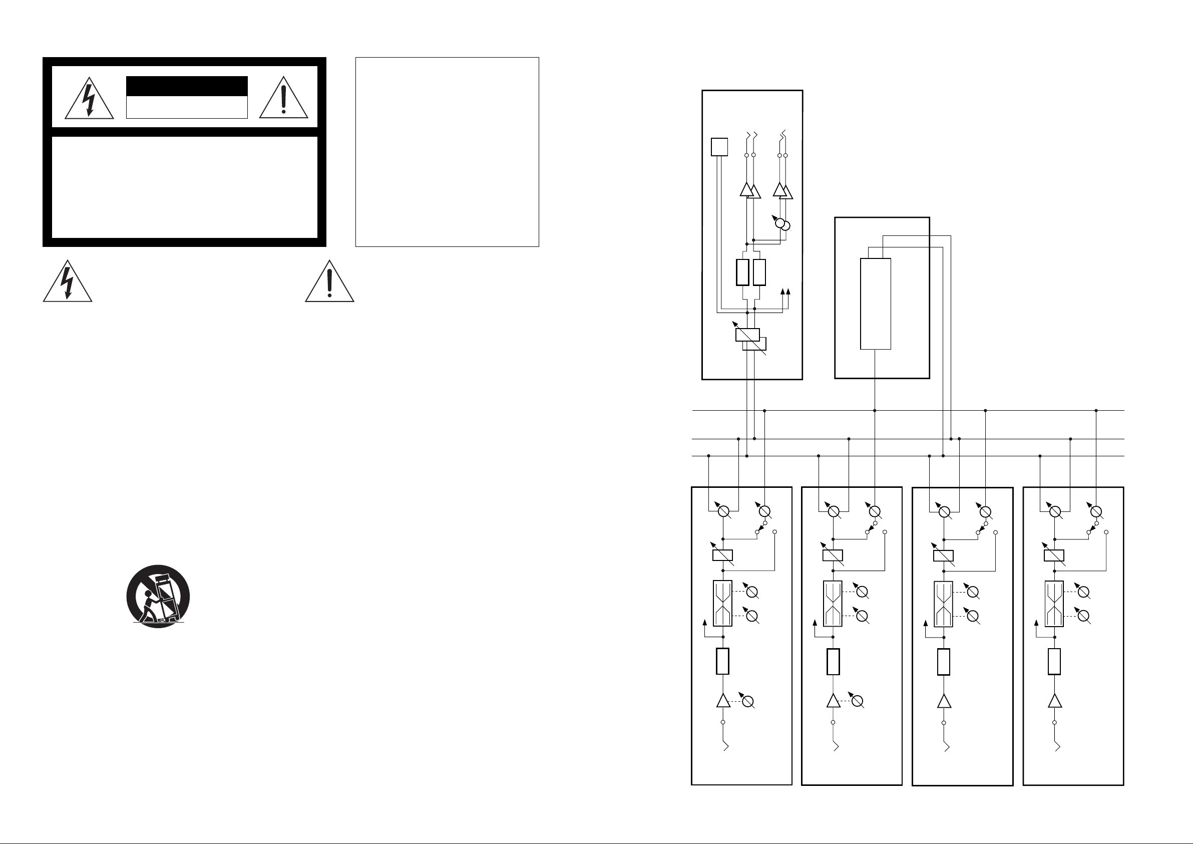
8. BLOCK DIAGRAMS
OUTPUT
(-10dBV)
R
D/A
PHONES
PHONES
METER
MASTER FADER
L
S/P DIF OUT
D/A
MASTER
EFFECT
EFFECT
SAFETY INSTRUCTIONS
1. Read instructions - All the safety and operating instructions
should be read before the appliance is operated.
2. Retain instructions - The safety and operating instructions
should be retained for future reference.
3. Heed warnings - All warnings on the appliance and in the
operating instructions should be adhered to.
4. Follow instructions - All operating and use instructions
should be followed.
5. Water and Moisture - The appliance should not be used near
water - for example, near a bathtub, washbowl, kitchen sink,
laundry tub, in a wet basement, or near a swimming pool,
and the like.
6. Carts and Stands - The appliance should be used only with a
cart or stand that is recommended by the manufacturer.
An appliance and cart combination should be moved with
care. Quick stops, excessive force, and uneven surfaces
may cause the appliance and cart combination to overturn.
7. Wall or Ceiling Mounting - The appliance should be mounted
to a wall or ceiling only as recommended by the manufacturer.
8. Ventilation - The appliance should be situated so that its location or position does not interfere with its proper ventilation. For example, the appliance should not be situated on a
bed, sofa, rug, or similar surface that may block the ventilation openings; or, placed in a built-in installation, such as a
bookcase or cabinet that may impede the flow of air through
the ventilation openings.
9. Heat - The appliance should be situated away from heat
sources such as radiators, heat registers, stoves, or other appliances (including amplifiers) that produce heat.
10. Power Sources - The appliance should be connected to a
power supply only of the type described in the operating instructions or as marked on the appliance.
11. Grounding or Polarization - The precautions that should be
taken so that the grounding or polarization means of an appliance is not defeated.
12. Power Cord Protection - Power supply cords should be routed
so that they are not likely to be walked on or pinched by items
placed upon or against them, paying particular attention to
cords at plugs, convenience receptacles, and the point where
they exit from the appliance.
13. Cleaning - The appliance should be cleaned only as recommended by the manufacturer.
14. Nonuse Periods - The power cord of the appliance should be
unplugged from the outlet when left unused for a long period
of time.
15. Object and Liquid Entry - Care should be taken so that objects
do not fall and liquids are not spilled into the enclosure
through openings.
16. Damage requiring Service - The appliance should be serviced
by qualified service personnel when:
A. The power supply cord or the plug has been damaged;
or
B. Objects have fallen, or liquid has been spilled into the
appliance; or
C. The appliance has been exposed to rain; or
D. The appliance does not appear to operate normally or
exhibits a marked changed in performance; or
E. The appliance has been dropped, or the enclosure dam-
aged.
17 Servicing - The user should not attempt to service the appli-
ance beyond that described in the operating instructions. All
other servicing should be referred to qualified service personnel.
EFFECT
R
L
METER
CH1
PAN
FADER
10kHz100Hz
A/D
INPUT 1
(-10dBV~-50dBV)
HI
LO
TRIM
EFFECT
SEND
PRE/POST
10kHz100Hz
METER
CH2
PAN
FADER
A/D
INPUT 2
(-10dBV~-50dBV)
TRIM
10kHz100Hz
METER
CH4
PAN
FADER
A/D
INPUT 4
(-10dBV)
EFFECT
SEND
PRE/POST
LO HI
METER
10kHz100Hz
PAN
FADER
EFFECT
SEND
PRE/POST
LO HI
EFFECT
SEND
PRE/POST
HI
LO
A/D
CH3
INPUT 3
(-10dBV)
23
Page 3
VM04VM04
TABLE OF CONTENTS
1. SPECIFICATIONS............................................................................ 4
R405
10KB
2
3
AD+5
R404
10KB
3
AD+5
R403
10KB
3
AD+5
1
ADGND
2
1
ADGND
2
1
ADGND
2. CONTROLS, INDICATORS AND CONNECTORS.................... 5
3. SERVICE MODE ............................................................................. 6
REPLACING THE BATTERY .............................................................................7
4. EXPLODED VIEW .......................................................................... 8
5. PARTS LIST..................................................................................... 9
6. PCB PATTERN DRAWING......................................................... 11
7. CIRCUIT DIAGRAMS .................................................................. 16
8. BLOCK DIAGRAMS..................................................................... 23
R402
10KB
2
3
AD+5
1
ADGND
NOTES
* Parts List and circuit diagrams are given in this manual to assist the service technician in maintaining the
Model VM04
R401
10KB
2
3
AD+5
1
ADGND
U401
EC12E
C
3
B
A
DGND
2
1
* The following accessories are supplied with VM04 as the standard accessories.
Owner's manual : 8288440000
AC adaptor AD-9B : 8270818003 (for USA/CND)
: 8270818006 (for EUR)
: 8270818007 (for UK)
: 8270818010 (for JPN)
* Following is the packing material for the Model VM04.
PACK, SIDE, L, VM04 : 8228446000
AD+5
PACK, SIDE, R, VM04 : 8228447000
AD+5
AD+5
AD+5
AD+5
VR0
VR1
VR2
VR3
<<<<<
1234567891011121314151617
ADGND
ADGND
ADGND
VR4
DGND
ADGND
JOG0
JOG1
<
<
DGND ADGND
DGND
CARTON, INNER, VM04 : 8228722000
CARTON, OUTER, VM04 : 8228901000
FADER PCB
J401
FPC-17P
To Main J11
CAUTION
Parts marked with this sign are safety critical components. They must always be replaced with
identical components. Refer to the Fostex Parts List and ensure exact replacement.
322
Page 4
1. SPECIFICATIONS
DEFINITION (Specification Unit : 0 dBV = 1 Vrms)
NORMAL FADER POSITION
Master fader ........................................................................................................... 80 position (Master Fader display)
Input fader........................................................................................................... 80 position (Channel Fader display)
Effect Send.................................................................................................................................................. 00 position
MIXER SECTION
INPUT 1, 2
Input Level .......................................................................................................................................-50dBV ~ -10dBV
Input Impedance ..................................................................................................................................... 20kΩ or more
Connector................................................................................................................... Ø6 mm Phone Jack/Unbalanced
INPUT 3, 4
Input Level ........................................................................................................................................................-10dBV
Input Impedance ..................................................................................................................................... 20kΩ or more
Connector................................................................................................................... Ø6 mm Phone Jack/Unbalanced
OUTPUT (L, R)
Output Level .....................................................................................................................................................-10dBV
Load Impedance...................................................................................................................................... 10kΩ or more
Connector................................................................................................................... Ø6 mm Phone Jack/Unbalanced
PHONES OUT
Output Level .........................................................................................................................20 mW MAX (16Ω load)
Load Impedance........................................................................................................................................ 16Ω or more
Connector............................................................................................................................ Ø6 mm Stereo Phone Jack
EQUALIZER
HI (Shelving Type) ...............................................................................................±18dB or more (-10dBV / 10 kHz)
LO (Shelving Type) ..............................................................................................±18dB or more (-10dBV / 100 Hz)
FREQUENCY RESPONSE
Input (-10dBV) → Stereo Out (-10dBV)............................................................................. +1, -2dB (20Hz ~ 20kHz)
Input (-50dBV) → Stereo Out (-10dBV)............................................................................. +1, -3dB (20Hz ~ 20kHz)
Input (-10dBV) → Phones Out (20mW/16Ω) ..................................................................... +1, -3dB (20Hz ~ 20kHz)
S/N (with DAT envelope filter)
Input (+2dBV) → Stereo Out (+2dBV)....................................................................................86dB or more (IHF-A)
Input (-38dBV) → Stereo Out (+2dBV)...................................................................................66dB or more (IHF-A)
Input ∑4 (+2dBV) → Stereo Out (+2dBV) .............................................................................. 81dB or more (IHF-A)
Phones Out Phones Out Residual Noise ................................................................................... 66dB or more (IHF-A)
DISTORTION (with DAT envelope filter)
Input (+2dBV) → Stereo Out (0dBV) ..........................................................................0.1% or less (100Hz ~ 10kHz)
Input (-40dBV) → Stereo Out (0dBV) .........................................................................0.1% or less (100Hz ~ 10kHz)
Input (0dBV) → Phones Out (20mW/16Ω) ................................................................................. 1.0% or less (1kHz)
CROSSTALK ................................................................................................................................... 60dB or more (1kHz)
SHOCK NOISE ..................................................................................................................................... -30dBVp-p or less
LEVEL INDICATION
Type ............................................................................................................................................ LCD Bargraph Meter
Number of Indicated Levels ...................................................... 11 dots (-48, -30, -24, -18, -12, -9, -6, -3, -1, 0, OL)
Reference Level (-10dBV) Indication ................................................................................................................ -12dB
DIGITAL SECTION
SAMPLING FREQUENCY ..................................................................................................................................44.1kHz
QUANTIZATION ........................................................................................................................................... 16 bit linear
A/D CONVERTER ......................................................20bit, 64 times Over Sampling Enhanced Dual Bit, Delta-Sigma
D/A CONVERTER .................................................................................... 20bit 128-time, Over Sampling, Delta-Sigma
S/P DIF OUT
Format ......................................................................................................................................... IEC 60958 (S/P DIF)
Connector...........................................................................................................................................................Optical
GENERAL
DC IN AD-9B, DC9V, 650 mA (the Center Positive)
DIMENSIONS................................................................................................................ 254 (W) × 186 (D) × 50 (H) mm
WEIGHT .................................................................................................................................................... Approx. 1.1 kg
POWER SUPPLY
USA/CND ............................................................................................................................................ 120VAC, 60Hz
EUR/UK.......................................................................................................................................... 230VAC, 50/60Hz
JPN 100VAC, 50/60Hz
VM04VM04
D303B
DIODE
S306
R326
NON
KEY0
R325
NON
D+5D+5
L302
LAMP
SEG4 0
SEG3 9
SEG3 8
SEG3 7
SEG3 6
SEG3 5
SEG3 4
SEG3 3
SEG3 2
SEG3 1
SEG3 0
SEG2 9
SEG2 8
SEG2 7
SEG2 6
SEG2 5
SEG2 4
SEG2 3
SEG2 2
SEG2 1
SEG2 0
SEG1 9
SEG1 8
SEG1 7
SEG1 6
SEG1 5
SEG1 4
SEG1 3
SEG1 2
SEG1 1
SEG1 0
SEG9
SEG8
SEG7
SEG6
SEG5
SEG4
SEG3
SEG2
SEG1
SEG[ 1. .40]
SEG3 8
SEG3 7
SEG3 6
SEG3 5
SEG3 4
SEG3 3
SEG3 2
SEG3 1
SEG3 0
SEG2 9
SEG2 8
SEG2 7
SEG2 6
SEG2 5
SEG2 4
SEG2 3
SEG4 0
40
SEG3 9
39
SEG3 8
38
SEG3 7
37
SEG3 6
36
SEG3 5
35
SEG3 4
34
SEG3 3
33
SEG3 2
32
SEG3 1
31
SEG3 0
30
SEG2 9
29
SEG2 8
28
SEG2 7
27
SEG2 6
26
SEG2 5
25
SEG2 4
24
SEG2 3
23
SEG2 2
22
SEG2 1
21
SEG2 0
20
SEG1 9
19
SEG1 8
18
SEG1 7
17
SEG1 6
16
SEG1 5
15
SEG1 4
14
SEG1 3
13
SEG1 2
12
SEG1 1
11
SEG1 0
10
SEG9
9
SEG8
8
SEG7
7
SEG6
6
SEG5
5
SEG4
4
SEG3
3
SEG2
2
SEG1
1
L301
SEG39
64
SEG3 8
65
SEG3 7
66
SEG3 6
67
SEG3 5
68
SEG3 4
69
SEG3 3
70
SEG3 2
71
SEG3 1
72
SEG3 0
73
SEG2 9
74
SEG2 8
75
SEG2 7
76
SEG2 6
77
SEG2 5
78
SEG2 4
79
SEG2 3
80
SEG22
COM1
COM2
COM3
COM4
COM5
COM6
COM7
COM13
COM12
COM11
COM10
COM9
SEG3 3
SEG2 8
SEG2 3
SEG1 8
SEG1 3
SEG4 0
SEG3 9
SEG3 8
SEG3 7
SEG1 6
U302
SEG1 0
LCD_FD4
SEG9
SEG8
SEG7
SEG6
COM16
COM15
COM14
COM13
COM12
COM11
COM10
COM9
SEG1
SEG2
SEG3
SEG4
SEG5
LAMP
DGND DGND
SEG40
COM11
COM12
COM13
COM14
COM15
COM16
62
SEG4063SEG39
SEG221SEG212SEG203SEG194SEG185SEG176SEG167SEG158SEG149SEG1310SEG1211SEG1112SEG1013SEG914SEG815SEG716SEG617SEG518SEG419SEG320SEG221SEG122GND23OSCI
SEG15
SEG16
SEG17
SEG18
SEG19
SEG20
SEG21
COM1
80
COM2
79
COM3
78
COM4
77
COM5
76
COM6
75
COM7
74
COM13
73
COM12
72
COM11
71
COM10
70
COM9
69
SEG3 3
68
SEG2 8
67
SEG2 3
66
SEG1 8
65
SEG1 3
64
SEG4 0
63
SEG3 9
62
SEG3 8
61
SEG3 7
60
SEG1 6
59
SEG1 0
58
SEG9
57
SEG8
56
SEG7
55
SEG6
54
COM16
53
COM15
52
COM14
51
COM13
50
COM12
49
COM11
48
COM10
47
COM9
46
SEG1
45
SEG2
44
SEG3
43
SEG4
42
SEG5
41
COM[1..16 ]
LCD_D3
LCD_D4
LCD_D5
LCD_D6
LCD_D7
COM1
COM2
COM3
COM4
COM5
COM6
COM7
COM8
COM9
COM10
55
COM1056COM1157COM1258COM1359COM1460COM1561COM16
U301
SEG11
SEG12
SEG13
SEG14
46
COM147COM248COM349COM450COM551COM652COM753COM854COM9
HD44780U
SEG1
SEG2
SEG3
SEG4
SEG5
SEG6
SEG7
SEG8
SEG9
SEG10
LCD_D2
24
KEY1
R324
NON
KEY2
R323
NON
KEY3
R322
NON
KEY4
D+5 D+5 D+5 D+5 D+5 D+5
R321
NON
KEY5
KEY[0..5]
C302
DB241DB342DB443DB544DB645DB7
R301
DGND
0.01
D+5
DB1
DB0
E
R/W
RS
D
M
VCC
CL2
CL1
V5
V4
V3
V2
V1
OSCO
220K
D+5
DGND
40
39
38
37
36
35
34
33
32
31
30
29
28
27
26
25
R3021KR3031KR3041KR3051KR306
TACT
D303A
DIODE
S305
TACT
D302B
DIODE
S304
TACT
D302A
DIODE
S303
TACT
D301B
DIODE
S302
TACT
D301A
DIODE
FADER ADJ CH1 C H2 CH3 CH4 VIEW
S301
TACT
DIG0
LCD_D1
LCD_D0
E
R/W
RS
1K
D306B
DIODE
S312
TACT
D305B
DIODE
S311
TACT
D304B
DIODE
S310
TACT
D306A
DIODE
S309
TACT
D305A
DIODE
S308
TACT
D304A
DIODE
RECAL L EFF TYPE EXI T STORE EFF PARAM E NTE R
S307
TACT
DIG1
DGND
DGND
KEY0
KEY1
KEY2
KEY3
KEY4
KEY5
DIG0
DIG1
LED_A0
1234567891011121314151617
J302
C301
0.1
DGND
D+5
DGND
LCD_D2
LCD_D3
LCD_D4
LCD_D5
LCD_D6
LCD_D7>
>>>>>>>>>
1234567891011121314151617
J301
5KB
R311
2
R307
3
10K
1
D-12
D356
NON
D355
LED
D354
LED
D353
LED
D352
LED
D351
LED
FADER ADJ CH1 CH2 CH3 CH4
LED_A0
LED_A1
LED_K0
LED_K1
LED_K2
LED_K3
LED_K4
LED_K5
FPC-1 7P
DGND
DGND
D+5
D+5
E
R/WRSLCD_D0
LCD_D1
>
D362
NON
LED_K0
D361
LED
LED_K1
D360
LED
LED_K2
D359
NON
LED_K3
D358
LED
LED_K4
D357
LED
RECAL L EFF TYPE STORE EFF PARAM
LED_K5
LED_A1
LED_A[0..1] DIG[0..1]
LED_K[0..5]
To Mai n J1 3
D-12DGND
D-12
FPC-1 7P
To Main J12
* Specifications and appearance are subject to change without notice for product improvement.
DISPLAY PCB
214
Page 5

J8
S
INPUT
-10-50
TRIMTRIM
-10-50
32 14
OUTPUT
LR
MIN MAX
PHONESFOOT SW
OUT
S/P DIF
9V
DC IN
RESET
123 45 6 7 8 9
EQ
VIEW
CHANNEL EDIT
MASTER4321
MAX
MIN
SCENE No
0
6
12
24
OL
1234LR1234
MIN
R
MAX
EFFHILOPAN
EQ
VIEWLEVEL
FADER ADJUST
ENTEREXIT
DATA
STORERECALL
SCENE
PARAMETERTYPE
EFFECT
SETUP
MAX
MIN
MAX
MIN
MAX
MIN
CH
MASTER
48
L
12 14 15 16
17
18
13
10
11
21
19
20
242522 23
231
4
VM04VM04
2. CONTROLS, INDICATORS AND CONNECTORS
< REAR PANEL >
PHONE
YKB21-5074
AGND
MASTER L
(-10dBV)
J6
YKB21-5074
231
4
AGND
L111
BEAD
U112
DTC314TK
1 3
AGND
2
1K
R115
R114
100K
AGND
C114
10/16
AGND
1
0.01
C113
A+5
C116
R113
27K
10P
84
3
2
C112
NON
R111
C111
10/16
U111A
NJM2115M
AGND
R112
100K
100K
R116
1K
R213
27K
10P
C213
C115
100/10
AGND
VBIAS3
L211
R215
C214
C212
C211
10/16
BEAD
1K
10/16
5
NON
MASTER R
J7
231
4
7
U111B
6
R211
100K
YKB21-5074
L121
(-10dBV)
AGND
BEAD
10
R126
R125
10K
AGND
C125
220/10
L221
C225
BEAD
10
R226
R225
10K
AGND
220/10
1. DC INLET connector [the Center Positive]
2. S/P DIF optical output connector [Optical]
3. FOOT SW (unlatched) jack [Ø6 mm Phone]
4. Headphone jack [Ø6 mm Stereo Phone]
6. Stereo OUTPUT L/R jacks [Ø6 mm Phone]
7. RESET switch
8. INPUT jacks [Ø6 mm Phone]
9. TRIM knobs
5. Headphone volume control knob
U212
DTC314TK
1 3
AGND
R124
4.7K
10P
2
R214
100K
AGND
NJM2115M
R212
100K
C215
R216
1K
VBIAS3
C124
100/10
AGND
C127
C121
10/16
AGND
100/10
84
A+5
3
C123
NON
C122
10/16
1K
R121
2
3
1
U122A
NJM3414AD
AGND
2
R123
470
R122
100K
C126
U121
DTC314TK
1 3
AGND
2
1
AGND
R131A
RK09 K12A
R224
4.7K
10P
C224
100/10
AGND
R127
1K
VBIAS4
C221
7
(DIP-8PIN)
U122B
NJM3414AD
5
6
R223
470
C223
NON
R222
100K
C226
100/10
AGND
C222
10/16
U221
2
1K
R221
4
5
1
R131B
10/16
RK09 K12A
R227
DTC314TK
1K
1 3
AGND
VBIAS4
AGND
< TOP PANEL >
AOUTL
AOUTR
R6
10K
31
D11
DAN202K
D+5
MAIN PCB : ANALOG OUT
R95
100K
C7
100/10
1
U12
DTA114EK
2 3
R94
10K
DGND D-12
DGND
MUTE
10. Contrast control knob
11. FADER ADJUST key
12. LCD display
13. View status indicator
14. SCENE Number display
15. SCENE RECALL key
16. SCENE STORE key
17. EFFECT PARAMETER key
18. EFFECT TYPE key
19. EXIT key
20. ENTER key
21. DATA encoder
22. CHANNEL EDIT key
23. Input faders
24. MASTER fader
25. VIEW key
520
Page 6

3. SERVICE MODE
3-1 Software Version Check
While holding down the EXIT key and ENTER key together, press the EFFECT TYPE key.
The LCD Display will show the Software Version of the VM04 for a second, and then return to
the Normal Mix mode.
3-2 Battery Check
While holding down the EXIT key and ENTER key together, press the EFFECT PARAMETER key .
· The LCD Display will show the voltage of the memor y backup battery inside the VM04 for
a second, and then return to the Normal Mix mode.
· If the voltage falls below 2.2V, the message “BattEmpty” will appear when powering ON.
· If the message “BattEmpty” is displayed, please replace the battery with the new one. For
exchanging procedure, please refer to the page 7.
3-3 Display Check
While holding down the EXIT key and ENTER key together, press the VIEW key.
· All the LEDs and LCD segments are supposed to start blinking. Check if they are correctly
blinking or not.
· Press the ENTER key would change the blinking pattern.
· If the key other than the ENTER key is pressed, the VM04 returns to Normal Mix mode display.
MASTERCH
MASTERCH
MASTERCH
Blink
VM04VM04
AIN3-
AIN3+
7
NJM2115M
U301B
R307 10K
5
6
C305
NON
10K
R306
AGND
1
0.01
C306
R304
0
NON
C303
84
A+5
3
C302
NON
C301
10/16
27K
R301
L301
231
4
U301A
NJM2115M
AGNDR305
2
NON
R303
100K
R302
47K
AGNDAGND
BEAD
C307
10/16
AGND
R308
1K
VBIAS3
C403
C406
R404
0
NON
AIN4+
R407 10K
0.01
84
A+5
C402
C401
10/16
R401
L401
10K
R406
AGND
3
NON
27K
231
AIN4-
7
NJM2115M
U401B
5
6
C405
NON
1
U401A
NJM2115M
AGNDR405
2
NON
R403
100K
R402
47K
AGNDAGND
BEAD
4
C407
10/16
AGND
R408
1K
VBIAS3
3-4 Fader Check
While holding down the EXIT key and ENTER key together , press the FADER ADJUST key.
· Confirm that each channel parameter value correctly appears on the
2ch1ch 4ch DATA encoder3ch
Character Display.
· Confirm that the SCENE NO. Display value would vary when rotating the DATA encoder.
· If any key is pressed, the VM04 returns to Normal Mix mode display.
3-5 Test Scene RECALL
While holding down the EXIT key and ENTER key together, press the SCENE RECALL key
· There are five Test Scenes (Test 1 ~ Test 5).
· Pressing the ENTER key would step forward the Test Scene.
· Pressing the key other than the ENTER key would return the VM04 to the Normal Mix mode display .
· Each Test Scene is set up as shown in the table below.
CH 1 CH 2 CH 3 CH 4
Level PAN Level PAN Level PAN Level PAN 1~4 ch
TEST 1 80 L 80 R 80 L 80 R 80 00 POST TEST 2 80 L 80 R 00 C 00 C 80 00 POST TEST 3 00 C 00 C 80 L 80 R 80 00 POST TEST 480L80L80L80L 80 00 POST -
TEST 500C00C00C00C 80 80 PREDelay
Eff Send
CH
MASTER
MAX
R
EffectMaster Pre/Post
SCENE NO.
MASTERCH
(-10dBV)
J4
YKB21-5074
INPUT3
AIN1-
AIN1+
7
NJM2115M
U101B
R109 10K
5
6
C105
NON
10K
R108
AGND
1
0.01
C106
R104
1M
100P
C103
84
A+5
C102
C101
10/16
18K
R101
3
2
NON
R103
R102
R110
20KC
1
2
U101A
NJM2115M
AGND
100K
22K
AGNDAGND
C107
220/10
R106
130
3
R107
100K
100P
C203
VBIAS1
AIN2+
R209 10K
10K
R208
AGND
0.01
C206
R204
1M
84
A+5
3
C202
NON
C201
10/16
18K
R201
(-10dBV)
J5
YKB21-5074
INPUT4
AIN2-
7
NJM2115M
U201B
5
6
C205
NON
R210
20KC
1
2
1
U201A
NJM2115M
AGND
2
R203
100K
R202
22K
AGNDAGND
C207
220/10
R206
130
3
R207
100K
VBIAS2
TEST 1 Line Check 1~4 Output Level / Frequency Response
TEST2 Line Check 1, 2 Output Level(Trim) / Frequency Response / Distortion / S/N(INPUT : Short)
TEST 3 Line Check 3, 4 Output Level / Frequency Response / Distortion / S/N(INPUT : Short)
TEST 4 Line Check 1~4 S/N(∑4, INPUT : Short)
TEST 5 Effect Check 1~4 Only the effect signal (1 Time Delay) is output.
CAUTION: While in the condition that the Test Scene is recalled, please do not turn off the po wer. Otherwise, correct Scene No. cannot be recalled.
L101
BEAD
231
4
J2
MAIN PCB : ANALOG IN
INPUT1
L201
BEAD
231
4
YKB21-5074
(-10dBV to -50dBV)
J3
YKB21-5074
(-10dBV to -50dBV)
INPUT2
196
Page 7

VM04VM04
D0D1D2D3D4D5D6
I/O021I/O122I/O223I/O325I/O426I/O527I/O628I/O7
D7
29
32
DGND
6
5
30
/OE
CE2
/WE
/CE1
While holding down the
· Pressing the ENTER key would clear the memory and the message “ClearMem!”
appear. All the setup will be initialized.
EXIT key and ENTER key together, press the SCENE ST ORE k ey
MASTER
D+5
· Pressing the key other than ENTER returns to the Normal Mix mode display (The
3-6 Memory Clear
A020A119A218A317A416A515A614A713A8
U8
A0A1A2A3A4A5A6A7A8A9A10
D7
[ANA]
[ANA]
AOUTL
AOUTR
AOUTR
0.1
C69
C70
1500P
R80 330
R82 330
R81 330
AIN4-
AIN4+
AIN3-
AIN3-
AIN4-
AIN4+
[ANA]
[ANA]
[ANA]
C61
1500P
C60
R79 330
AIN3+ AOUTL
10/16
AIN3+
C59
0.1
[ANA]
0.1
C58
10
R71
A+5
76
77
78
79
80
81
82
83
84
85
86
87
88
89
90
91
92
93
94
95
96
97
98
99
100
AGND
C57
0.01
C56
0.01
C55
0.01
C54
0.01
C53
0.01
C52
0.01
C51
10/16
71
75
DZF2
DZF1
NC
AVB
NC
AVSS
NC
AINR-
AINL-
VCO M
AVSS
AVDD
AVB
NC
69
72
70
73
68
DVB74DVB
DVSS
DVSS
DVDD
DVDD
DZFSET
AOUTR2
AOUTL2
AOUTR1
AOUTL1
VRD AL
AVDD
VRD AH
AINR+
AINL+
VRA DL
VRA DH
TSTI11OPCL2/PDAD3/PDDA4/PD5/RST6TSTIO17TSTIO28TSTIO39DVB10DVB11SDIN212SDAD13SDOUT214SDDA15SDDA216SDOUT317SDOUT118SDIN119SMODE20BCLK21LRCK22CLKO23DVDD24DVSS
/PD_ADDA
/PD_DSP
/RST_DSP
/RST_DSP
/PD_ADDA
/PD_DSP
[CPU]
[CPU]
[CPU]
FXS_DATA
FXS_DATA
D0D1D2D3D4D5D6
A0A1A2A3A4A5A6A7A8
59
/OE60IO061IO162IO263IO364IO465IO566IO667IO7
U7
AK7712A
CLOCK MASTER
R73 330
R72 330
DG_OUT_DATA
AIN34_DATA
ST_DATA
AIN34_DATA
ST_DATA
[DSP]
[DSP]
[DSP]
A851A752A653A554A455A356A257A158A0
DVDD
50
DVSS
49
A9
48
A10
A11
A12
A13
A14
A15
A16
/WE
/RASCE
/CASRF
SO
DRDY
WRDY
SI
SCLK
DVDD
DVSS
/WRQ
/CS
TSTI2
XTO
XTI
25
R74 100
R76 330
R75 100
D+5
MSCK
LRCK
BCK
LRCK
MSCK
BCK
[DSP]
[DSP]
[DSP]
A9
47
A10
46
A11
45
A12
44
A13
43
A14
42
A15
41
A16
40
/WE
39
38
37
36
35
34
33
32
31
30
29
28
27
26
X2
C66
0.01
C65
0.01
C64
0.01
C63
0.01
C62
10/16
DGND
1
5
2
3
4
LRS
LRCK
UBDA
BLOCK
U9
28
D+5
C81
0.01
DGND
16.9344MHZ
BCK
DATA6VLDY
3
C68
22P
C67
22P
8
7
9
COPY
EMPH
C82
10/16
D+5
A92A1031A111A1212A134A1411A157A16
A11
A12
A13
A14
A15
DGND DGND
/CS_DSP _EF F
/WRQ_DSP
[CPU]
[CPU]
1312
U5F
74VHC14
1110
U5E
74VHC14
13
14
11
12
XI
FS110FS2
VSS
CKS
DO115DO216M117M218IS119IS220CTG121CTG222CTG323FR3224LBIT25CKA126CKA227VDD
TC9271F
R91
100
C83
0.01
123
10
A16
SO
SCK
[CPU]
[CPU]
DGND
DGND
VSS
VCC
TC551001CFT-70L
8
24
C77
0.01
C76
10/16
D+5
DGND
R77 100
SI
DRDY_DSP_EF F
WRDY_DSP
SI
[CPU]
[CPU]
[CPU]
Scene No. 00 is displayed.) and the memory will not be initialized.
· Pressing the RESET SW would also clear the memory and the message “ClearMem!”
appear.
Gain Table
The value appears in the LCD display corresponds
to the gain in dB as shown below.
INPUT F ader
MASTER Fader
EFFECT Send
Value
00
01
05
10
15
20
25
30
35
40
45
50
55
60
65
70
75
80
85
90
95
99
Gain (dB)
- ∞
-72.0
-55.0
-42.5
-35.0
-28.75
-23.0
-18.0
-15.5
-13.0
-10.5
-8.5
-7.0
-5.5
-4.0
-2.5
-1.25
0
+1.5
+3.0
+4.67
+6.0
REPLACING THE BATTERY
If the voltage of the inside memory backup battery falls below 2.2V,
the message “BattEmpty” will appear when powering ON.
Parts No.:8239120000
CAUTION
· Replacing the battery with the new one would basically
initialize the backup data.
· In order to retain the backup data, please replace the
battery while powering on.
BATTERY, 3V, CR2032
B001
Value
L10
L9
L8
L7
L6
L5
L4
L3
L2
L1
C
R1
R2
R3
R4
R5
R6
R7
R8
R9
R10
PAN
Gain (dB)
Left
0.0
-0.1
-0.25
-0.4
-0.7
-1.0
-1.4
-1.8
-2.2
-2.6
-3.0
-4.2
-5.5
-7.1
-9.0
-11.3
-14.1
-17.6
-23.5
-32.0
- ∞
MASTER
Right
- ∞
-32.0
-23.5
-17.6
-14.1
-11.3
-9.0
-7.1
-5.5
-4.2
-3.0
-2.6
-2.2
-1.8
-1.4
-1.0
-0.7
-0.4
-0.25
-0.1
0.0
MAIN PCB : DSP (EFFECT)
U10
GPIF32T
718
Page 8

4. EXPLODED VIEW
1
2
VM04VM04
A
11
75
73
4
3
BTT 3x8 BZn
12
B 3x8
CZn
13
C47
C48
1500P
1500P
0.1
C41
14
C40
R56 330
R58 330
R57 330
AIN2-
AIN2-
5
6
BTT 3x8 BZn
16
15
[ANA]
R55 330
AIN2+
AIN1-
AIN1+
AIN1-
AIN2+
[ANA]
AIN1+
[ANA]
[ANA]
10/16
C39
0.1
0.1
C38
10
R52
76
77
78
79
80
81
82
83
84
85
86
87
88
89
90
91
92
93
94
95
96
97
98
99
100
C37
C36
C35
C34
C33
C32
DVB74DVB
DZF2
DZF1
NC
AVB
AOUTR2
AOUTL2
NC
AOUTR1
AOUTL1
VRDAL
AVSS
AVDD
VRDAH
NC
AINR-
AINR+
AINL-
AINL+
VCOM
VRADL
AVSS
AVDD
VRADH
AVB
NC
TSTI11OPC L2/PDAD3/PDDA4/PD5/RS T6TSTIO17TSTIO28TSTIO39DVB10DVB11SDIN212SDAD13SDOUT214SDDA15SDDA216SDOUT317SDOUT118SDIN119SMODE20BCLK21LRCK22CLKO23DVDD24DVSS
AGND
0.01
0.01
0.01
0.01
0.01
0.01
68
69
72
70
71
DVSS
DVSS
DVDD
DVDD
DZFS E T
U6
AK7712A
/PD_ADDA
/PD_DS P
/RS T_DSP
/RS T_DSP
/PD_ADDA
/PD_DS P
AIN34_DATA
8
10
C31
8
BTT 3x8
BZn
A+5
10/16
[CPU]
[CPU]
[CPU]
AIN34_DATA
7
59
/OE60IO061IO162IO263IO364IO465IO566IO667IO7
CLOCK SLAVE
R53 330
R54 330
FXS_DATA
ST_DATA
FXS_DATA
ST_DATA
A851A752A653A554A455A356A257A158A0
DVDD
50
DVSS
49
A9
48
A10
47
A11
46
A12
45
A13
44
A14
43
A15
42
A16
41
/WE
40
/RASCE
39
/CASRF
38
SO
37
DRDY
36
WRDY
35
SI
34
SCLK
33
DVDD
32
DVSS
31
/WRQ
30
/CS
29
TSTI2
28
XTO
27
XTI
26
25
MSCK
C46
0.01
C45
LRCK
BCK
C44
LRCK
BCK
[DSP]
[DSP]
C43
C42
D+5
MSCK
0.01
[DSP]
0.01
0.01
10/16
DGND
SCK
/CS _DSP_C H
/WRQ_DS P
[CPU]
[CPU]
[CPU]
R51
100
DRDY_DSP _C H
WRDY_DSP
SO
[CPU]
SI
[CPU]
[CPU]
[CPU]
BTT 3x8
BZn
[DSP]
[DSP]
[DSP]
9
BTT 3x8 BZn
17
18
6
BTT 3x8
A
BZn
MAIN PCB : DSP (CHANNEL)
178
Page 9

VM04VM04
7. CIRCUIT DIAGRAMS
AIN1+
AIN1-
AIN2+
AIN2-
AIN1+
AIN1-
AIN2+
ANALOG IN
ANA_IN.SCH
DSP(CHANNEL)
DSP_CH.SC H
R39
10K
R38
10K
R37
10K
R36
10K
R35
10K
R34
10K
R33
330
R32
10K
D+5
C15
0.1
DGND
D+5B
U5A
R15
R49
D+5
VR[0 .. 4]
AD+5
VR0
AD+5
AD+5
AD+5
AD+5
>
1234567891011121314151617
MAIN PCB : CPU
J11
AIN2-
AIN1+
AIN1-
AIN2+
AIN2-
BCK
AIN2-
AIN1-
AIN2-
AIN1-
AIN2+
AIN1+
AIN2+
AIN1+
/RST_DSP
/CS_DSP_CH
/WRQ_DSP
DRDY_DSP_CH
/RST_DSP
/CS_DSP_CH
/WRQ_DSP
DRDY_DSP_CH
WRDY_DSP
/RST_DSP
/WRQ_DSP
/WRQ_ DSP
/RST_D SP
/CS_DSP_EFF
/CS_DSP_CH
/PD_DSP
SO
SCK
AD+5
/PD_ADDA
VR2
<
52
VR3
<
53
VR4
<
54
<
55
BATT_VOL
<
56
<
57
58
<
59
KEY0
<
KEY1
60
<
KEY2
61
<
KEY3
62
<
KEY4
63
<
KEY5
64
74VHC14
U5C
1 2
5 6
C21
0.01
DGND
47K
R16
47K
10K
R50
10K
D+5
VR1
VR2
VR3
VR4
ADGND
ADGND
ADGND
>
>
>
>
BCK
LRCK
LRCK
MSC K
MSC K
ST_DATA
ST_DATA
FXS_DATA
FXS_DATA
AIN34 _DATA
AIN34 _DATA
/PD_DSP
/PD_ADDA
WRDY_DSP
SI
SCK
SO
/PD_DSP
/PD_ADDA
WRDY_DSP
SI
SCK
SO
SOSISCK
/PD_ADDA
/PD_DSP
/WRQ_DSP
R31 100
0.1
C16
ADGND
VR0
VR1
<
49
51
47
48
VASS
VAREF
P60/AIN050P61/AIN1
P62/AIN2
P63/AIN3
P64/AIN4
P65/AIN5
P66/AIN6
P67/AIN7
VDD
P70
P71
P72
P73
P74
P75
P761P772P003P014P025P036P047P058P069P0710P10//INT011P11/INT112P12/INT2/TC113P13//DVO14P14//PPG15P15/TC216P1617P1718P20//INT5//STOP
<
<
<><><><><><><><> >
R13
10K
D+5
MUTE
LCD_ D0
LCD_ D1
LCD_ D2
74VHC14
C22
0.01
DGND
ADGNDDGND
JOG0
JOG1
DGND
DGND
ADGND
>
>
FPC-17P
TO FADER J401
AIN3+
AIN3-
AIN3+
AIN3-
LRCK
BCK
MSCK
AIN34_DATA
FXS_D AT A
ST_DATA
ST_DATA
ST_DATA
/WRQ_DSP
/WRQ_DSP
DSP(E FFECT)
DSP_EFF.SCH
/WRQ_DSP
/RST_DSP
R30 100
/RST_DSP
/WRQ_DSP
DRDY_DSP_CH
DRDY_DSP_EFF
<
<
<
>< >
44
45
P5346P54
P50/INT3/TC343P51/INT4/TC4
P52//PWM//PDO
LCD_ D3
LCD_ D4
LCD_ D5
LCD_ D6
D+5
DGND
LCD_ D0
<><><><><><><><><<<
1234567891011121314151617
J12
FXS_DATA
FXS_DATA
AIN34 _DATA
AIN34 _DATA
/RST_DSP
/CS_DSP_EFF
/RST_DSP
/CS_DSP_EFF
/RST_DSP
/CS_DSP_EFF
R29
100
/CS_DSP_CH
/CS_DSP_EFF
/PD_DSP
>
>
>
42
40
41
P46/SI2
P47/SO2
U4
TMP87CM40AF
>
JOG_0
LCD_ D7
WRDY_DSP
LCD_ D1
LCD_ D2
LCD_ D3
AIN3+
AIN3-
BCK
BCK
LRCK
LRCK
AIN3+
MSC K
AIN3+
MSC K
/PD_DSP
WRDY_DSP
DRDY_DSP_EFF
/PD_DSP
WRDY_DSP
DRDY_DSP_EFF
/PD_ADDA
/PD_DSP
WRDY_DSP
SO
/CS_DSP_CH
R27 100
R28 100
SI
SCK
SO
/PD_ADDA
<
>
>
>
>
36
39
37
38
P43/SI1
P44/SO1
P42//SCK1
P45//SCK2
><<<<< >
LCD_ E
LCD_ R/W
LCD_ RS
JOG_1
LCD_ D4
LCD_ D5
LCD_ D6
LCD_ D7
LCD_ E
AIN3-
AIN3-
/PD_ADDA
/PD_ADDA
DIG1
>
LCD_ R/W
AIN4+
AIN4+
AIN4+
AIN4+
AIN4+
SO
SO
SOSISCK
DIG0
>
P3633P3734P4035P41
19
/STOP
LCD_ RS
AIN4-
D+5
D+5
AIN4-
AIN4-
AIN4-
AIN4-
SI
SI
SCK
SCK
R26 100
D+5
SCK
SCK
31
R12
L4
BEAD
FOOT SW
DGND
DGND
ANALOG OUT
1K
231
J10
D-12
ANA_OUT.SCH
P35
P34
P33
P32
P31
P30
VSS
XOUT
XIN
/RESET
P22/XTOUT
P21/XTIN
TEST
D+5B
D6
DAN202K
31
4
DGNDD-12
FPC-17P
AOUTL
AOUTR
MUTE
AOUTL
AOUTR
MUTE
AOUTL
AOUTR
A+5
AOUTL
AOUTL
AOUTR
AOUTR
A+5
LED_A0
Q1
2SA1050
D+5
32
31
30
29
28
27
26
25
24
23
22
21
20
R99
C99
D7
TO LCD J3 0 1
D+5
R24
1K
DIG0
<
LED5
<
LED4
<
LED3
<
LED2
<
LED1
<
LED0
<
<
3
DTC114EK
U11
1
DGND
10K
100p
DAN202K
DGND
YKF21-5074
DGND
2
U5B
R2
100K
31
D+5B
D8
DAN202K
D10
3 1
DAN202K-1
U5D
74VHC14
9 8
D+5
3
R96
10K
U1
2
DTC114EK
R92
6.8K
DGND
KEY0
KEY1
KEY2
KEY3
DGND
1234567891011121314151617
J13
5. PARTS LIST
EXPLODED VIEW
VBIAS2
C94
100/10
C93
0.01
R431KR44
1K
AGND
VBIAS1
C92
100/10
C91
0.01
R411KR42
1K
AGND
LED_A1
Q2
2SA1050
R25
1K
DIG1
R23
75
LED_K5
R22
75
LED_K4
R21
75
LED_K3
R20
75
LED_K2
R19
75
LED_K1
R18
75
LED_K0
DGND
X1
8MHZ
33P
C20
C19 33P
DGND
74VHC14
S001
3 4
SKHVL H
DGND
C6
0.01
C18
10/16
DGND
R17
100K
1
DGND
DIG[0. .1 ]
LED_K[0 .. 5]
R93
2.2K
KEY4
KEY5
DIG0
DIG1
LED_K0
LED_K1
LED_K2
LED_K3
LED_K4
LED_A0
LED_A1
VBIAS3
C96
100/10
C95
0.01
R451KR46
A+5
1K
AGND
No. Part No. Description
1 8212653000 WINDOW, LCD, VM04
2 8226239001 KNOB, FADER, N4.5
3 8212652100 PANEL, TOP, VM04
4 8226238000 KNOB, JOG, FD-4
5 8274167000 PCB ASSY , FADER, VM04
6 8276839615 CABLE, FLAT, FFC, 17P, L150
7 8274166000 PCB ASSY , DISPLA Y, VM04
VBIAS4
C98
100/10
C97
0.01
R471KR48
A+5
1K
AGND
8 8226246001 BUTTON, 7X13, LED
9 8226246002 BUTTON, 7X13, N4.5
10 8216 695000 SHEET, LED, VM04
11 822 1266000 SHIELD, MAIN, VM04
12 821 6 6 9 4 0 0 0 SHIELD, EMI, VM04
13 8274165000 PCB ASSY , MAIN, VM04
14 8239 1 20 0 0 0 BATTERY, 3V, CR2032
15 821 6 69 9 0 0 0 SHEET, BATTERY, VM04
16 82212 6 5100 PANEL, BOTTOM, VM04
U5G
VCC14GND
7
74VHC14
17 8260561000 Foot, Assy
18 827 0 8 1 8 0 03 AC adaptor, AD-9B, USA/CND
827081800 6 AC adaptor, AD-9B, EUR
C23
0.01
D+5B
DGND
D-12
C11
100/16
R4
1K
D4
DSK10 C
U3
NJM2360
1
8
1
R3
+12V
R5
8.2K
2
5
ES
INV
CS
CT
GND
CD
V+6SI
7
L3
68UH
C10
0.0012UF
3
4
C9
100/10
DGND
8274165000 PCB ASSY ,MAIN,VM04
Ref.No. Part No. Description
U001 82365701 0 1 IC, ST, DG, DRIVER, DTC114EK
U003 823654130 0 IC, ST, AN, DC-DC, NJM2360AM
U004 823608520 1 IC, QFP, DG, CPU, VM04
U005 823654501 4 IC, ST, TSSOP, 74VHC14
U006, 007 8236084 9 0 0 IC, QFP, DG, DSP, AK7712A
U008 8236084600 IC, TSOP, SRAM, TC551001CFT-70L
U009 82365049 0 0 IC, ST, DG, DIGITAL OUT, TC9271F
U010 8245317000 CONN, OPT, TOTX178
U011 82365701 0 1 IC, ST, DG, DRIVER, DTC114EK
U012 82365704 01 IC, ST, DG, DRIVER, DTA114EK
U013, 014 82365403 01 IC, ST, REGULATOR, NJM78M05DLA
U101~401 8236505011 IC, ST, AN, OPAMP, NJM2115M(TEI)
82708180 0 7 AC adaptor, AD-9B, UK
82708180 1 0 AC adaptor, AD-9B, JPN
ICs
U111 82365050 11 IC, ST, AN, OPAMP, NJM2115M(TEI)
U112, 212 82365702 01 IC, ST, DG, DRIVER, DTC314TK
U121, 221 82365702 01 IC, ST, DG, DRIVER, DTC314TK
BATT _VO L
(To CPU)
C24
10/16
D+5B
D9
AD+5A+5
C5
100/10
C4
0.01
L2
22UH
C3
0.01
AGND ADGNDGND
C2
100/10
C27
0.01
1
O
2
U13
I
78M05DLA
3
LED_A[0 .. 1]
0.01
C26
SB05-05CP
R1
10K
+
DGND
B1
D5
DSK10 C
CR2032
D+5
C8
100/10
D3
DSK10 C
C29
0.01
1
O
2
U14
I
78M05DLA
3
D2
DSC10C
3 1
0.01
C28
U122 823603750 0 IC, DIP, AN, NJM3414AD
TRANSISTOR
Ref.No. Part No. Description
Q001, 002 82341008 02 TR, VT, PNP, 2SA1150Y
DIODEs
Ref.No. Part No. Description
D002~004 8234019612 D, VT, DSK10C-ET1
D005 8234019612 D, VT, DSK10C-ET1
D006, 007 823450280 0 D, ST, DAN202K
D008 823450280 0 D, ST, DAN202K
D009 82345021 0 0 D, ST, SCHOTTKY, SB05-05CP
D010 823450280 0 D, ST, DAN202K
D011 823450280 0 D, ST, DAN202K
RESISTORs
Ref.No. Part No. Description
R001 8230 50 01 0 3 ST, CARBON, 1/10W, 10K, 5%
R002 82305 0 01 04 ST, CARBON, 1/10W, 100K, 5%
R003 82305 0 01 09 ST, CARBON, 1/10W, 1, 5%
R004 82305 00 1 0 2 ST, CARBON, 1/10W, 1K, 5%
C1
470/16
+12V
231
LED_K5
J1
YKB31-0014
R005 8230 50 0 82 2 ST, CARBON, 1/10W, 8.2K, 5%
R006 8230 50 01 0 3 ST, CARBON, 1/10W, 10K, 5%
R012 82305 00 1 0 2 ST, CARBON, 1/10W, 1K, 5%
R013 8230 50 01 0 3 ST, CARBON, 1/10W, 10K, 5%
R015, 016 82 3 05 0 04 7 3 ST, CARBON, 1/10W, 47K, 5%
R017 82305 0 01 04 ST, CARBON, 1/10W, 100K, 5%
R018~023 823050075 0 ST, CARBON, 1/10W, 75, 5%
R024, 025 8230 5001 02 ST, CARBON, 1/10W, 1K, 5%
FPC-17P
TO KEY J302
R026~031 823050010 1 ST, CARBON, 1/10W, 100, 5%
R032 8230 50 01 0 3 ST, CARBON, 1/10W, 10K, 5%
Ref.No. Part No. Description
R033 8230500331 ST, CARBON, 1/10W, 330, 5%
R034~039 8230500103 ST, CARBON, 1/10W, 10K, 5%
R041~046 8230500102 ST, CARBON, 1/10W, 1K, 5%
R047, 048 8230500102 ST, CARBON, 1/10W, 1K, 5%
R049, 050 8230500103 ST, CARBON, 1/10W, 10K, 5%
R051 8230500101 ST, CARBON, 1/10W, 100, 5%
R052 8230500100 ST, CARBON, 1/10W, 10, 5%
R053, 054 8230500331 ST, CARBON, 1/10W, 330, 5%
R055~058 8230500331 ST, CARBON, 1/10W, 330, 5%
R071 8230500100 ST, CARBON, 1/10W, 10, 5%
R072, 073 8230500331 ST, CARBON, 1/10W, 330, 5%
R074, 075 8230500101 ST, CARBON, 1/10W, 100, 5%
R076 8230500331 ST, CARBON, 1/10W, 330, 5%
R077 8230500101 ST, CARBON, 1/10W, 100, 5%
R079~082 8230500331 ST, CARBON, 1/10W, 330, 5%
R090 8230500103 ST, CARBON, 1/10W, 10K, 5%
R091 8230500101 ST, CARBON, 1/10W, 100, 5%
R092 8230500103 ST, CARBON, 1/10W, 10K, 5%
R093 8230500222 ST, CARBON, 1/10W, 2.2K, 5%
R094 8230500103 ST, CARBON, 1/10W, 10K, 5%
R095 8230500104 ST, CARBON, 1/10W, 100K, 5%
R096 8230500103 ST, CARBON, 1/10W, 10K, 5%
R101, 201 8230500183 ST, CARBON, 1/10W, 18K, 5%
R102, 202 8230500223 ST, CARBON, 1/10W, 22K, 5%
R103, 203 8230500104 ST, CARBON, 1/10W, 100K, 5%
R104, 204 8230500105 ST, CARBON, 1/10W, 1M, 5%
R106, 206 8230500131 ST, CARBON, 1/10W, 130, 5%
R107, 207 8230500104 ST, CARBON, 1/10W, 100K, 5%
R108, 208 8230500103 ST, CARBON, 1/10W, 10K, 5%
R109, 209 8230500103 ST, CARBON, 1/10W, 10K, 5%
R110, 210 824015401 0 POT, PL, RT9, 20KC, RK09K111
R111, 211 8230500104 ST, CARBON, 1/10W, 100K, 5%
R112, 212 8230500104 ST, CARBON, 1/10W, 100K, 5%
R113, 213 8230500273 ST, CARBON, 1/10W, 27K, 5%
R114, 214 8230500104 ST, CARBON, 1/10W, 100K, 5%
R115, 215 8230500102 ST, CARBON, 1/10W, 1K, 5%
R116, 216 8230500102 ST, CARBON, 1/10W, 1K, 5%
R121, 221 8230500102 ST, CARBON, 1/10W, 1K, 5%
R122, 222 8230500104 ST, CARBON, 1/10W, 100K, 5%
R123, 223 8230500471 ST, CARBON, 1/10W, 470, 5%
R124, 224 8230500472 ST, CARBON, 1/10W, 4.7K, 5%
R125, 225 8230500103 ST, CARBON, 1/10W, 10K, 5%
R126, 226 8230500100 ST, CARBON, 1/10W, 10, 5%
R127, 227 8230500102 ST, CARBON, 1/10W, 1K, 5%
R131 8240168003 POT, PI, RT 9, 50KAA, RK09K12A
R301, 401 8230500273 ST, CARBON, 1/10W, 27K, 5%
R302, 402 8230500473 ST, CARBON, 1/10W, 47K, 5%
R303, 403 8230500104 ST, CARBON, 1/10W, 100K, 5%
R304, 404 8230500000 ST, CARBON, 1/10W, 0, 5%
R306, 406 8230500103 ST, CARBON, 1/10W, 10K, 5%
R307, 407 8230500103 ST, CARBON, 1/10W, 10K, 5%
R308, 408 8230500102 ST, CARBON, 1/10W, 1K, 5%
Ref.No. Part No. Description
C001 8232143477 VT , ALU, 16V, 470µF, 20%
C002 8232142107 VT , ALU, 10V, 100µF, 20%
C003, 004 8233504103 ST, CER, 25V, 0.01µF, 10%
C005 8232142107 VT , ALU, 10V, 100µF, 20%
C006 8233504103 ST, CER, 25V, 0.01µF, 10%
C007 8232142107 VT , ALU, 10V, 100µF, 20%
C008 8232142107 VT , ALU, 10V, 100µF, 20%
C009 8232143107 VT , ALU, 16V, 100µF, 20%
C010 8233500122 ST, CER, 50V, 0.0012µF, 10%
C011 8232143107 VT , ALU, 16V, 100µF, 20%
C015 8233502104 ST, CER, 50V, 0.1µF, +80
C016 8233502104 ST, CER, 50V, 0.1µF, +80
C018 8232143106 VT , ALU, 16V , 10µF, 20%
C019, 020 8233500330 SAP, ST, CER, 50V, 33pF, 5%
C021, 022 8233504103 ST, CER, 25V, 0.01µF, 10%
C023 8233504103 ST, CER, 25V, 0.01µF, 10%
C024 8232143106 VT , ALU, 16V , 10µF, 20%
C025 8233500101 ST, CER, 50V, 100pF, 5%
RESISTORs
CAPACITORs
ALU = Electrolytic
CER = Ceramic type
916
Page 10

VM04VM04
CAPACITORs
ALU = Electrolytic
CER = Ceramic type
Ref.No. Part No. Description
C026~029 8233504103 ST, CER, 25V, 0.01µF, 10%
C031 8232143106 VT , ALU, 16V, 10µF, 20%
C032~037 8233504103 ST, CER, 25V, 0.01µF, 10%
C038, 039 8233502104 ST, CER, 50V, 0.1µF, +80
C040 8232143106 VT , ALU, 16V, 10µF, 20%
C041 8233502104 ST, CER, 50V, 0.1µF, +80
C042 8232143106 VT , ALU, 16V, 10µF, 20%
C043~046 8233504103 ST, CER, 25V, 0.01µF, 10%
C047, 048 8233500152 ST, CER, 50V, 0.0015µF, 5%
C051 8232143106 VT , ALU, 16V, 10µF, 20%
C052~057 8233504103 ST, CER, 25V, 0.01µF, 10%
C058, 059 8233502104 ST, CER, 50V, 0.1µF, +80
C060 8232143106 VT , ALU, 16V, 10µF, 20%
C061 8233502104 ST, CER, 50V, 0.1µF, +80
C062 8232143106 VT , ALU, 16V, 10µF, 20%
C063~066 8233504103 ST, CER, 25V, 0.01µF, 10%
C067, 068 8233500220 ST, CER, 50V, 22pF, 5%
C069, 070 8233500152 ST, CER, 50V, 0.0015µF, 5%
C076 8232143106 VT , ALU, 16V, 10µF, 20%
C077 8233504103 ST, CER, 25V, 0.01µF, 10%
C081 8233504103 ST, CER, 25V, 0.01µF, 10%
C082 8232143106 VT , ALU, 16V, 10µF, 20%
C083 8233504103 ST, CER, 25V, 0.01µF, 10%
C091 8233504103 ST, CER, 25V, 0.01µF, 10%
C092 8232142107 VT , ALU , 10V, 100µF, 20%
C093 8233504103 ST, CER, 25V, 0.01µF, 10%
C094 8232142107 VT , ALU , 10V, 100µF, 20%
C095 8233504103 ST, CER, 25V, 0.01µF, 10%
C096 8232142107 VT , ALU , 10V, 100µF, 20%
C097 8233504103 ST, CER, 25V, 0.01µF, 10%
C098 8232142107 VT , ALU , 10V, 100µF, 20%
C101, 201 8232143106 VT, ALU, 16V, 10µF, 20%
C103, 203 8233500101 ST, CER, 50V, 100pF, 5%
C106, 206 8233504103 ST, CER, 25V, 0.01µF, 10%
C107, 207 8232142227 VT, ALU, 10V, 220µF, 20%
C111, 211 8232143106 VT, ALU, 16V, 10µF, 20%
C113, 213 8233500100 ST, CER, 50V, 10PF, 5%
C114, 214 8232143106 VT, ALU, 16V, 10µF, 20%
C115, 215 8232142107 VT, ALU, 10V, 100µF, 20%
C116 8233504103 ST, CER, 25V, 0.01µF, 10%
C121, 221 8232143106 VT, ALU, 16V, 10µF, 20%
C122, 222 8232143106 VT, ALU, 16V, 10µF, 20%
C124, 224 8233500100 ST, CER, 50V, 10pF, 5%
C125, 225 8232142227 VT, ALU, 10V, 220µF, 20%
C126, 226 8232142107 VT, ALU, 10V, 100µF, 20%
C127 8232142107 VT , ALU , 10V, 100µF, 20%
C301, 401 8232143106 VT, ALU, 16V, 10µF, 20%
C306, 406 8233504103 ST, CER, 25V, 0.01µF, 10%
C307, 407 8232143106 VT, ALU, 16V, 10µF, 20%
MISCELLANEOUS
Ref.No. Part No. Description
B001 8239121000 HOLDER, BATTERY, BCR20H4
E801 8239120000 BATTERY, 3V, CR2032
J001 8245544000 CONN, DC INLET, YKB31-0014
J002~005 8245339004 CONN, JACK, PHONE, YKB21-5074
J006, 007 8245339004 CONN, JACK, PHONE, YKB21-5074
J008 8245339004 CONN, JACK, PHONE, YKB21-5074
J010 8245339004 CONN, JACK, PHONE, YKB21-5074
J011 8245272017 CONN, PI, JACK, FPC 17P
J012 8245272017 CONN, PI, JACK, FPC 17P
J013 8245272017 CONN, PI, JACK, FPC 17P
L002 8242196223 COIL, PVT, 22µH, 5%, LF5.0S
L003 8242214031 COIL, PVT, 68µH, 5%, ELES
L004 8242501121 FILTER, EMI, 120, 25%, MMZ2012S
L101~401 8242501121 FILTER, EMI, 120, 25%, MMZ2012S
L111, 211 8242501121 FILTER, EMI, 120, 25%, MMZ2012S
L121, 221 8242501121 FILTER, EMI, 120, 25%, MMZ2012S
S001 8253469000 SW, PLT, TACT, SKHVLH
X001 8256134003 RESONATOR, PF, CER, 8.00MHZ
X002 8256170004 RESONATOR, ST, XTL, 16.9344MHZ
Y1501 8245340000 NUT, PHONEJACK
8251972201 Plain PCB, MAIN, VM04
8274165000 PCB ASSY , DISPLA Y , VM04
ICs
Ref.No. Part No. Description
U301 8236083600 IC, QFP, DG, LCD DRIVER, HD44780
U302 8256176000 MODULE, DISPLAY, LCD, FD-4
DIODEs
Ref.No. Part No. Description
D301~306 8234502800 D, ST, DAN202K
D351 8234504001 OPT, VT , LED, RED, LT3D31W
D352 8234504003 OPT, VT , LED, YLW, L T3H31W
D353 8234504003 OPT, VT , LED, YLW, L T3H31W
D354 8234504003 OPT, VT , LED, YLW, L T3H31W
D355 8234504003 OPT, VT , LED, YLW, L T3H31W
D357 8234504004 OPT, VT , LED, GRN, LT3E31W
D358 8234504003 OPT, VT , LED, YLW, L T3H31W
D360 8234504001 OPT, VT , LED, RED, LT3D31W
D361 8234504003 OPT, VT , LED, YLW, L T3H31W
RESISTORs
Ref.No. Part No. Description
R301 8230500224 ST, CARBON, 1/10W, 220K, 5%
R302~306 8230500102 ST, CARBON, 1/10W, 1K, 5%
R307 8230500752 ST, CARBON, 1/10W, 7.5K, 5%
R311 8240151004 POT, PI, RT9, 5KB, L20, RK09K113
R321~326 8230500103 ST, CARBON, 1/10W, 10K, 5%
CAPACITORs
CER = Ceramic type
Ref.No. Part No. Description
C301 8233502104 ST, CER, 50V, 0.1µF, +80
C302 8233504103 ST, CER, 25V, 0.01µF, 10%
MISCELLANEOUS
Ref.No. Part No. Description
J301, 302 8245272117 CONN, PL, JACK, FPC, 17P
L301, 302 8239116000 LAMP, 5V, 75MA
S301~312 8253135002 SW, PT, TACT, SOR-112HS
Y301 8212611000 PLATE, REFLECT, LCD, FD-4
8251972102 Plain PCB, DISPLAY, VM04
8274167000 PCB ASSY , FADER, VM04
IC
Ref.No. PartNo. Description
U401 8253466000 SW, PI, ENCODER, EC12E
RESISTOR
Ref.No. PartNo. Description
R401~405 8240274005 POT, PI, SL30, 10KB, RS30H111
MISCELLANEOUS
Ref.No. PartNo. Description
J401 8245272117 CONN, PL, JACK, FPC, 17P
8251972003 Plain PCB, FADER, VM04
U401
R405
R404
R403
R402
R401
FADER PCB : PARTS SIDE
J401
17
1
8251972 003
F ADER, VM04
U401
FADER PCB : FOIL SIDE
R401
R402
R403
R404
R405
J401
17 1
1510
Page 11

DISPLAY PCB : FOIL SIDE
S302
DISPLAY, VM04
8251972 102
D301
D352
D353
1
S303
D354
17
S304
J302 KEY J301 LCD
D355
S305
17
R321
R322
D303
R323
R324
R325
R326
D356
S306
D359
D306
S312 S309
D362
1
D302
R307
D351
S301
R311
R306
R305
R303
R304
L301
4180
R302
R301
24
25
U301
1
80
C302
40
65
4164
U302
D305
S308
D358
S311
D361
D304
C301
L302
S307
D357
S310
D360
40 1
MAIN PCB : PARTS SIDE
C5
C24
R1
D9
D7
B1
L2
C3
D2D3D5
U14
C28 C29
C1
U10
C2
U13
C26 C27
C82
C83
C225 C125
R12 L4
C4
J1
R13
C127
R91
D6
U9
15
C81
C9
R224 R223
C224 C223
U122
C124 C123
R124
R123
R225
R226
R3
L221
1
5
C226
R122
C126
R125
C23
U3
R126
R2
R92
R222
L121
8
R96
1
R227
D8
U5
U1
D4
R127
C222
C122
C121
R221
L3
C98
R121
1
C11
R131
R50
R49
U221
U121
C221
R214
C96
17
R23
17
R17
Q2 Q1
E
D10 U11
C214
TO FADER
R19
R20
R21
R22
E
C7
R211
R216
R212
C215
U212
L211
R215
TO KEY
R18
D11
R6
C211 C111
C212
R213
C213
C114
R114
R112
U12
U111
R115
1
C116
J13
J11
R95
R111
C112
C113
U112
C16
1
1
R94
17
R116
C115
R113
L111
U4
R408
C407
R405
C403
J12
R404
C406
C402
U401
R401 L401
TO LCD
R403
C401
R402 R301 L301
S1
1
R407
C405
C18
R308
R303
C301
R302
C25
C17
R90
C307
R305
C303
6. PCB PATTERN DRAWING
8251972 200
MAIN, VM04
R51
R55
C106
U101
30
C40
C105
C41
R110
20
C8
1
R53
R54
C38
R109
C62
1
50
40
U8
X1
17
C306
C302
R304
U301
R307
C51
C305
60
70
R71
R43
C94 C201
R202
80 90 100
C70 C69
R82
R81
C203
R201
U7
R77
R80
R204
R79
30
C202
L201
C60
X2
R76
R75
R74
R73
20
R72
C58
1
C61
C206
U201
R209
C205
R102
C207 C107
R210
60
70
R52
C31
R41
C103
C92 C101
R101
C42
50
C48 C47
40
U6
80 90 100
R58
R57
R56
R104
C102
L101
1114
J10 J8
J7 J6
J5 J4 J3 J2
VM04VM04
Page 12

MAIN PCB : FOIL SIDE
R109
1
C38
20
R54
R53
C8
C213
C211 C111
R18
R213
L211
R212
C7
E
R19
R211
R20
J7 J6
R131
C96
R215
R214
C214
U212
C215
R216
Q2 Q1
C221
U121
U221
D10 U11
E
R17
C11
17
R23
R21
R22
17
TO FADER
R49
R50
L121
R221
R121
C121
C122
C222
R222
C98
R227
R127
L3
1
D4
U3
R96
R92
U1
1
C23
8
U5
R2
D8
R126
C126
R122
C226
1
R125
5
L221
R3
R226
R123
U9
R225
R124
C124 C123
U122
C224 C223
R224 R223
C9
C81
15
J10 J8
U10
C83
C82
C26 C27
R12 L4
C225 C125
C127
R13
D7
D6
D9
C24
R91
U13
U14
D2
D3
D5
C2
B1
R1
C3
C5
J1
C1
C28 C29
L2
C4
J5 J4 J3 J2
C92 C101
R41
R102
R209
R72
R73
R74
R75
R76
R210
C207 C107
C302
17
R302
C405
U401
R407
C301
C303
R303
C18
C406
R404
J12
1
R90
R305
C307
R308
C25
X1
C17
C58
C205
1
20
U201
C206
C61
X2
C60
L201
C202
R79
30
R204
R80
R77
R202
R201
C305
U301
R307
C94 C201
C203
R43
R82
R81
C70 C69
80 90 100
R71
U7
40
70
60
50
C62
C306
R304
C51
U8
1
C402
U4
S1
R115
R401 L401
R402 R301L301
L111
U112
R113
C401
C403
R405
C407
R408
R403
C115
R111
R116
R95
TO LCD
17
R94
1
R114
C114
C116
C113
1
C112
U111
C212
R112
R6
D11
U12
J13
TO KEY
J11
1
C16
R110
L101
C102
R57
40
R104
R58
C48 C47
80 90 100
R101
C103
C31
R52
70
60
50
C42
C41
C105
C40
U101
30
C106
R55
R51
R56
U6
MAIN, VM04
8251972 200
DISPLAY PCB : PARTS SIDE
U302
R311
1
3
L301 L302
D351
S301
1
41
40
D357
S307
D358
80
S308
D360
S310
D361
S311
1312
D352
S302
J301
(LCD)
D353
1
S303
D354
17
S304
1
D355
S305
17
J302
(KEY & LED)
D356
S306
D359
S309
D362
S312
VM04VM04
 Loading...