

Page 1

Service Manual
Model
VC-8
ADAT/ANALOG Converter
Page 2
CAUTION
RISK OF ELECTRIC SHOCK
DO NOT OPEN
CAUTION:
TO PREVENT ELECTRIC SHOCK, MATCH
WIDE BLADE OF PLUG TO WIDE SLOT,
FULLY INSERT.
CAUTION: TO REDUCE THE RISK OF ELECTRIC SHOCK,
DO NOT REMOVE COVER (OR BACK).
NO USER-SERVICEABLE PARTS INSIDE.
REFER SERVICING TO QUALIFIED SERVICE PERSONNEL.
The lightening flash with arrowhead symbol,
within an equilateral triangle, is intended to
alert the user to the presence of uninsulated
“dangerous voltage” within the product's enclosure that may be of sufficient magnitude to
constitute a risk of electric shock to persons.
“WARNING”
“TO REDUCE THE RISK OF FIRE OR ELECTRIC SHOCK, DO
NOT EXPOSE THIS APPLIANCE TO RAIN OR MOISTURE.”
SAFETY INSTRUCTIONS
1. Read instructions - All the safety and operating instructions
should be read before the appliance is operated.
2. Retain instructions - The safety and operating instructions
should be retained for future reference.
3. Heed warnings - All warnings on the appliance and in the operating instructions should be adhered to.
4. Follow instructions - All operating and use instructions should
be followed.
5. Water and Moisture - The appliance should not be used near
water - for example, near a bathtub, washbowl, kitchen sink,
laundry tub, in a wet basement, or near a swimming pool, and
the like.
6. Carts and Stands - The appliance should be used only with a
cart or stand that is recommended by the manufacturer.
An appliance and cart combination should be moved with
care. Quick stops, excessive force, and uneven surfaces
may cause the appliance and cart combination to overturn.
7. Wall or Ceiling Mounting - The appliance should be mounted to
a wall or ceiling only as recommended by the manufacturer.
8. Ventilation - The appliance should be situated so that its location or position does not interfere with its proper ventilation. For example, the appliance should not be situated on a
bed, sofa, rug, or similar surface that may block the ventilation openings; or, placed in a built-in installation, such as a
bookcase or cabinet that may impede the flow of air through
the ventilation openings.
ATTENTION:
POUR ÉVITER LES CHOCS ÉLECTRIQUES,
INTRODUIRE LA LAME LA PLUS LARGE DE
LA FICHE DANS LA BORNE CORRESPONDANTE DE LA PRISE ET POUSSER
JUSQU' AU FOND.
The exclamation point within an equilateral
triangle is intended to alert the user to the
presence of important operating and maintenance (servicing) instructions in the literature
accompanying the appliance.
9. Heat - The appliance should be situated away from heat
sources such as radiators, heat registers, stoves, or other appliances (including amplifiers) that produce heat.
10. Power Sources - The appliance should be connected to a
power supply only of the type described in the operating instructions or as marked on the appliance.
11. Grounding or Polarization - The precautions that should be
taken so that the grounding or polarization means of an appliance is not defeated.
12. Power Cord Protection - Power supply cords should be routed
so that they are not likely to be walked on or pinched by items
placed upon or against them, paying particular attention to
cords at plugs, convenience receptacles, and the point where
they exit from the appliance.
13. Cleaning - The appliance should be cleaned only as recommended by the manufacturer.
14. Nonuse Periods - The power cord of the appliance should be
unplugged from the outlet when left unused for a long period of
time.
15. Object and Liquid Entry - Care should be taken so that objects
do not fall and liquids are not spilled into the enclosure through
openings.
16. Damage requiring Service - The appliance should be serviced
by qualified service personnel when:
A. The power supply cord or the plug has been damaged;
or
B. Objects have fallen, or liquid has been spilled into the
appliance; or
C. The appliance has been exposed to rain; or
D. The appliance does not appear to operate normally or
exhibits a marked changed in performance; or
E. The appliance has been dropped, or the enclosure damaged.
17 Servicing - The user should not attempt to service the appli-
ance beyond that described in the operating instructions. All
other servicing should be referred to qualified service personnel.
Page 3

TABLE OF CONTENTS
1. SPECIFICATIONS.............................................................................................4
2. CONTROLS, INDICATORS AND CONNECTORS..................................... 5
3. EXPLODED VIEW ...........................................................................................6
4. PARTS LIST......................................................................................................8
5. PCB PATTERN DRAWING..........................................................................10
6. CIRCUIT DIAGRAMS ...................................................................................12
VC-8
NOTES
* Parts List and circuit diagrams are given in this manual to assist the service technician in
maintaining the Model VC-8.
* The following accessories are supplied with VC-8 as the standard accessories.
Owner's manual, VC-8, MLT : 8288444000
AC adaptor AD-12A : 8270727003 (for USA/CND)
: 8270727006 (for EUR)
: 8270727007 (for UK)
: 8270727010 (for JPN)
* Following is the packing material for the Model VC-8.
PACK, SIDE, L, DE-1 : 8228454000
PACK, SIDE, R, DE-1 : 8228455000
CARTON, INNER, VC-8 : 8228727000
CARTON, OUTER, VC-8 : 8228906000
CAUTION
Parts marked with this sign are safety critical components. They must always be replaced
with identical components. Refer to the Fostex Parts List and ensure exact replacement.
3
Page 4

VC-8
1. SPECIFICATIONS (Specification Unit : 0 dBV = 1 Vrms)
INPUT 1~8
Connector RCA pin jack
Input Impedance 20kΩ or more
Input Level -10dBV
OUTPUT 1~8
Connector RCA pin jack
Load Impedance 10kΩ or more
Output Level -10dBV
DATA IN/OUT
Connector Square shape optical
Format IEC60958 (S/P DIF)
ALESIS Proprietary Multi Channel Optical Interface
WORD IN
Connector BNC type
Input Impedance Terminate switch ON : 75Ω
Terminate switch OFF : Hi impedance
Input Level Hi Level : 3.5~5V
Lo Level : 0~1V
DIGITAL SECTION
Quantization 20-bit linear
AD Converter 20 bit 64 times over sampling ∆∑ modulation
DA Converter 20 bit 128times over sampling ∆∑ modulation
Sampling Frequency INT mode : 44.1kHz
OPTICAL/WORD mode : 32~48kHz
CHARACTERISTICS
Overall Frequency Responce +1, -2dB (20Hz~20kHz)
Dynamic Range (overall) 90dB or more
T.H.D. 0.008% or less (at 1kHz,+2dB)
Channel Separation 80dB or more (at 1kHz)
S/N (overall) 90dB or more
Phase Difference between Channel 20˚ or less
Click Noise Power ON/OFF : -20dBV or less
GENERAL
Dimensions 220 (W) x 43 (H) x 200 (D) mm
Weight 1.0kg (Excluding accessories)
Power Supply DC12V, 600mA, Exclusive AC Adaptor (AD-12A)
* Specifications and appearance are subjects to change without notice for product improvement.
* Adat and the marks are trademarks of Alesis Corporation.
4
Page 5
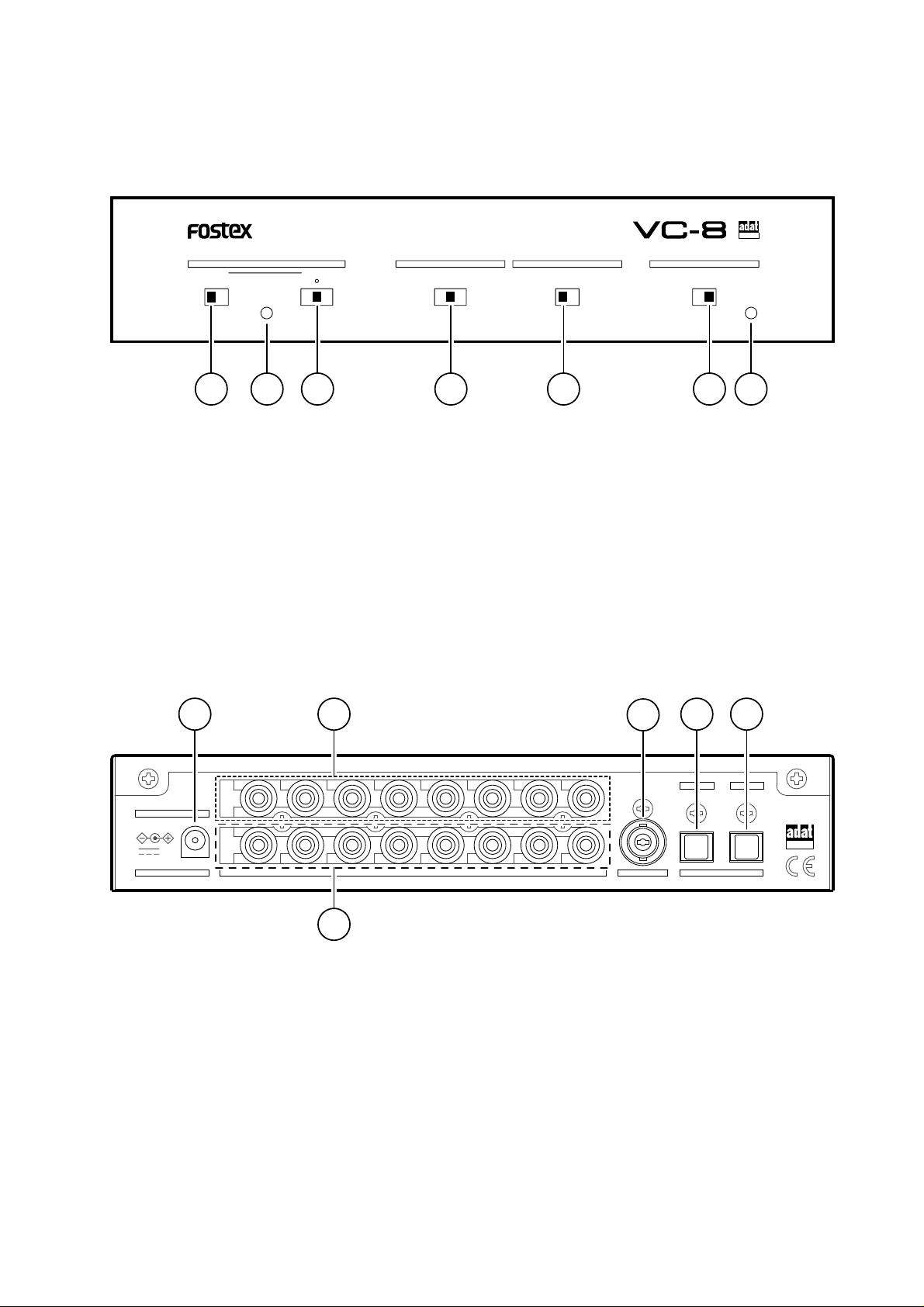
2. CONTROLS, INDICATORS AND CONNECTORS
< Front Side >
VC-8
75Ω
OFFON
< Rear Side >
WORD
LOCKED
ANALOG INPUT MODECLOCK DIGITAL MODE
1-4 1-81-2 ONSTBYINT(44.1k)OPTICAL
1. WORD IN terminate switch
2. LOCKED LED
3. CLOCK select switch
4. ANALOG INPUT MODE switch
5. DIGITAL MODE select switch
6. POWER switch
7. POWER LED
ADAT/ANALOG CONVERTER
POWER
S/P DIFADAT
5432167
OPTICAL
8 9
AD-12A ONLY
12V
DC IN
IN
OUT
8
11
768
76
54321
ANALOG
WORD IN DIGITAL
10
8. DC IN jack [Center: Plus +]
9. ANALOG INPUT connectors 1~8 [RCA]
10. ANALOG OUTPUT connectors 1~8 [RCA]
11. WORD IN connector [BNC]
12. DIGITAL INPUT connectors [Square shape optical]
13. DIGITAL OUTPUT connectors [Square shape optical]
1312
OUTIN54321
OPTICAL
5
Page 6
VC-8
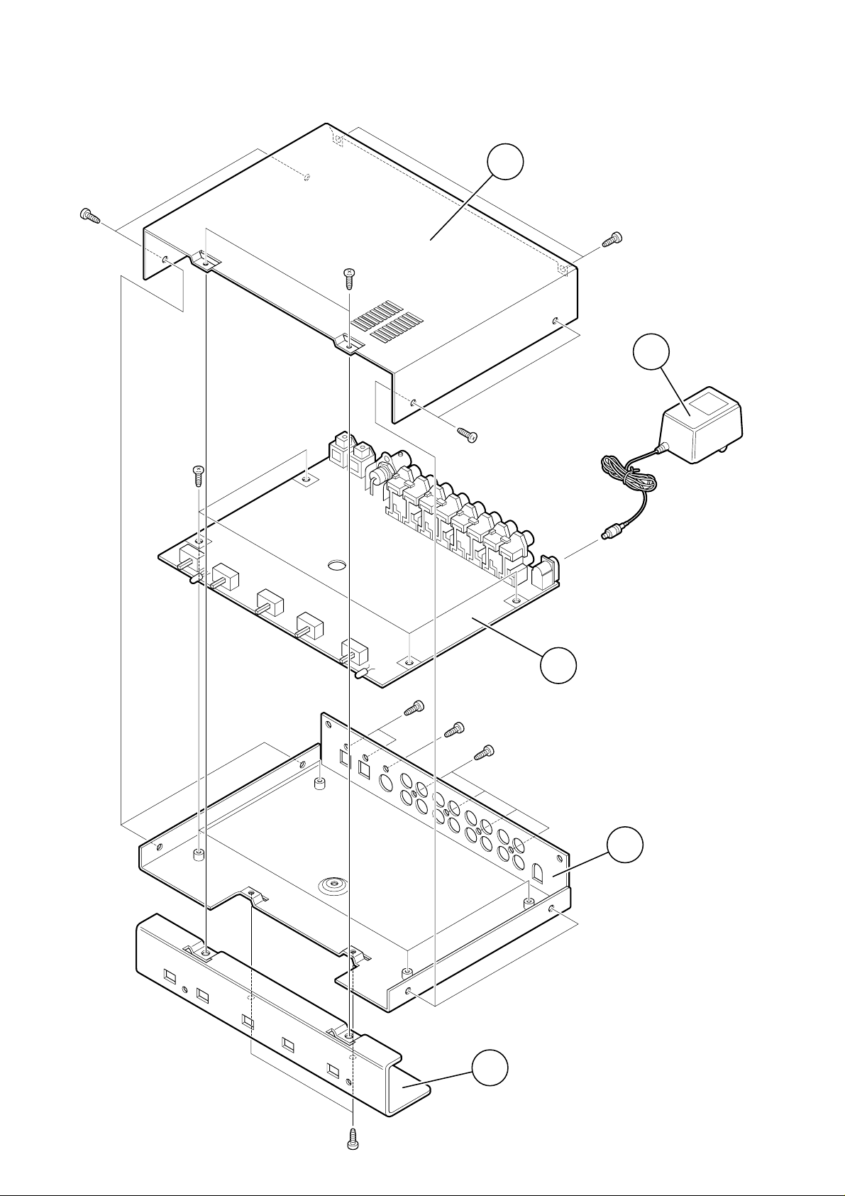
3. EXPLODED VIEW
1
BBT3x8
BZn
BBT3x8
BZn
BBT3x8
BZn
2
BBT3x8
BZn
B3x6
CZn
BBT3x8
BZn
B3x6
BZn
3
BBT3x8
BZn
4
5
BBT3x8
BZn
6
Page 7

Ref. No. Part No. Description
1 8221288000 PANEL ,TOP, DE-1
2 8270727003 AC ADAPTOR, AD-12A, USA/CND
8270727006 AC ADAPTOR, AD-12A, EUR
8270727007 AC ADAPTOR, AD-12A, UK
8270727010 AC ADAPTOR, AD-12A, JPN
3 8274201000 PCB_ASSY, VC-8
4 8221291000 CHASSIS, VC-8
5 8221290000 PANEL, FRONT, VC-8
8260561000 FOOT_ASSY, S
VC-8
CAUTION :
The “PARITY SW (S001)” on the MAIN PCB assy must be set “ON”.
7
Page 8

VC-8
4. PARTS LIST
• MAIN PCB ASSY
Ref. No. Part No. Description
8274201000 PCB_ASSY, VC-8
B101 8251525200 PLAIN_PCB, VC-8
ICs
Ref. No. Part No. Description
U001 8236541610 ST, AN, REGULATOR, UPD29M10T
U002~004 8236540301 ST, AN, REGULATOR, L78M05T-TL
U005 8236545904 ST, TSSOP, 74VHCU04
U006 8236085000 QFP, DG, GATE_ARRAY, DIF
U007 8236502500 ST, AN, RESET, NJM2103M
U008, 009 8236545163 ST, TSSOP, TC74VHC163
U010, 011 8236545153 ST, TSSOP, TC74VHC153
U012 8236503400 ST, DG, VCO, TC9246F
U013, 014 8236570101 ST, DG, DRIVER, DTC114EK
U015~017 8236545074 ST, TSSOP, 74VHC74
U018 8236545000 ST, TSSOP, 74VHC00
U019 8236545161 ST, TSSOP, 74VHC161
U020 8236545086 ST, TSSOP, 74VHC86
U021, 022 8236570101 ST, DG, DRIVER, DTC114EK
U023 8236570801 ST, DG, DRIVER, DTB114TK
U024 8236545074 ST, TSSOP, 74VHC74
U025 8236545904 ST, TSSOP, 74VHCU04
U026 8236503400 ST, DG, VCO, TC9246F
U027 8236570401 ST, DG, DRIVER, DTA114EK
U029, 030 8236545157 ST, TSSOP, 74VHC157
U031 8236545000 ST, TSSOP, 74VHC00
U032 8236541300 ST, AN, DC-DC, NJM2360AM
U034, 035 8236570401 ST, DG, DRIVER, DTA114EK
U101~801 8236505011 ST, AN, OPAMP, NJM2115M(TEI)
U151~451 8236541700 ST, DG, ADDA, AK4522
U153~453 8236541200 ST, AN, OPAMP, NJM4565M
U157~857 8236570201 ST, DG, DRIVER, DTC314TK
DIODEs
Ref. No. Part No. Description
D001 8234101400 OPT, VT, LED, GRN, LT3K8B
D002 8234502800 D, ST, DAN202K
D003 8234750600 D, ST, RB400D
D004 non
D005 8234202700 OPT, V, LED, GRN-RED, GL3ED8
D006, 007 8234502800 D, ST, DAN202K
D008 8234108400 D, VT, SCHOTTKEY, EK03W
D009~011 8234502800 D, ST, DAN202K
RESISTORs
Ref. No. Part No. Description
R001 8230500681 ST, CARBON, 1/10W, 680, 5%
R002 8230500101 ST, CARBON, 1/10W, 100, 5%
R003 8230500332 ST, CARBON, 1/10W, 3.3K, 5%
R004 8230500222 ST, CARBON, 1/10W, 2.2K, 5%
R005 8230500105 ST, CARBON, 1/10W, 1M, 5%
R006 8230500000 ST, CARBON, 1/10W, 0, 5%
R007 8230500101 ST, CARBON, 1/10W, 100, 5%
R008 8230500561 ST, CARBON, 1/10W, 560, 5%
RESISTORs
Ref. No. Part No. Description
R009 8230500331 ST, CARBON, 1/10W, 330, 5%
R010 8230500101 ST, CARBON, 1/10W, 100, 5%
R011~013 8230500103 ST, CARBON, 1/10W, 10K, 5%
R014 8230500101 ST, CARBON, 1/10W, 100, 5%
R015 8230500751 ST, CARBON, 1/10W, 750, 5%
R016 8230500472 ST, CARBON, 1/10W, 4.7K, 5%
R017 non
R018 8230500331 ST, CARBON, 1/10W, 330, 5%
R019 non
R020, 021 8230500101 ST, CARBON, 1/10W, 100, 5%
R022 non
R023 8230500102 ST, CARBON, 1/10W, 1K, 5%
R024, 025 8230500103 ST, CARBON, 1/10W, 10K, 5%
R026 8230508101 R, ST, ARRAY, 100x4, 5%, CN1J4
R027 8230500101 ST, CARBON, 1/10W, 100, 5%
R029 8230500103 ST, CARBON, 1/10W, 10K, 5%
R030 8230500222 ST, CARBON, 1/10W, 2.2K, 5%
R031, 032 8230500102 ST, CARBON, 1/10W, 1K, 5%
R033, 034 8230500104 ST, CARBON, 1/10W, 100K, 5%
R035 8230500561 ST, CARBON, 1/10W, 560, 5%
R036 8230500152 ST, CARBON, 1/10W, 1.5K, 5%
R037 8230500224 ST, CARBON, 1/10W, 220K, 5%
R038, 039 8230500101 ST, CARBON, 1/10W, 100, 5%
R040 8230500681 ST, CARBON, 1/10W, 680, 5%
R041~043 8230500101 ST, CARBON, 1/10W, 100, 5%
R044 8230500681 ST, CARBON, 1/10W, 680, 5%
R045 8230500104 ST, CARBON, 1/10W, 100K, 5%
R048 8230500104 ST, CARBON, 1/10W, 100K, 5%
R049 8230500103 ST, CARBON, 1/10W, 10K, 5%
R050, 051 8230500101 ST, CARBON, 1/10W, 100, 5%
R054 8230500103 ST, CARBON, 1/10W, 10K, 5%
R055 8230500101 ST, CARBON, 1/10W, 100, 5%
R056 8230500750 ST, CARBON, 1/10W, 75, 5%
R057 8230500103 ST, CARBON, 1/10W, 10K, 5%
R058 8230500159 ST, CARBON, 1/10W, 1.5, 5%
R059 8230500105 ST, CARBON, 1/10W, 1M, 5%
R060, 061 8230500561 ST, CARBON, 1/10W, 560, 5%
R062 8230500103 ST, CARBON, 1/10W, 10K, 5%
R063, 064 8230500473 ST, CARBON, 1/10W, 47K, 5%
R065 8230500101 ST, CARBON, 1/10W, 100, 5%
R101~801 8230500183 ST, CARBON, 1/10W, 18K, 5%
R102~802 8230500752 ST, CARBON, 1/10W, 7.5K, 5%
R103~803 8230500103 ST, CARBON, 1/10W, 10K, 5%
R104~804 8230500103 ST, CARBON, 1/10W, 10K, 5%
R105~805 8230500331 ST, CARBON, 1/10W, 330, 5%
R106~806 8230500331 ST, CARBON, 1/10W, 330, 5%
R109~809 8230500104 ST, CARBON, 1/10W, 100K, 5%
R111~811 8230500103 ST, CARBON, 1/10W, 10K, 5%
R112~812 8230500123 ST, CARBON, 1/10W, 12K, 5%
R113~813 8230500222 ST, CARBON, 1/10W, 2.2K, 5%
R114~814 8230500104 ST, CARBON, 1/10W, 100K, 5%
R151~451 8230500100 ST, CARBON, 1/10W, 10, 5%
R152~452 8230500101 ST, CARBON, 1/10W, 100, 5%
R153~453 8230500100 ST, CARBON, 1/10W, 10, 5%
R156~856 8230500101 ST, CARBON, 1/10W, 100, 5%
8
Page 9

VC-8
CAPACITORs
ALU = Electrolytic type
CER = Ceramic type
Ref. No. Part No. Description
C001~003 8232143106 VT, ALU, 16V, 10µF, 20%, SME-VB
C004 8232142107 VT, ALU, 10V, 100µF, 20%, SME-VB
C005~008 8232143106 VT, ALU, 16V, 10µF, 20%, SME-VB
C009 8232143477 VT, ALU, 16V, 470µF, 20%, SME-VB
C010~012 8232143106 VT, ALU, 16V, 10µF, 20%, SME-VB
C013~020 8233502104 ST, CER, 50V, 0.1µF, +80, CC20F
C021~024 8233504103 ST, CER, 25V, 0.01µF, 10%, CC20R
C025 8233500471 ST, CER, 50V, 470pF, 5%, CC20SL
C026, 027 8233504103 ST, CER, 25V, 0.01µF, 10%, CC20R
C028, 029 8233500471 ST, CER, 50V, 470pF, 5%, CC20SL
C030~034 8233504103 ST, CER, 25V, 0.01µF, 10%, CC20R
C035 8233502104 ST, CER, 50V, 0.1µF, +80, CC20F
C036~042 8233504103 ST, CER, 25V, 0.01µF, 10%, CC20R
C043, 044 8233500101 ST, CER, 50V, 100pF, 5%, CC20SL
C045 8233500470 ST, CER, 50V, 47pF, 5%, CC20SL
C046 8233504103 ST, CER, 25V, 0.01µF, 10%, CC20R
C047, 048 8233500220 ST, CER, 50V, 22pF, 5%, CC20SL
C049~051 8233504103 ST, CER, 25V, 0.01µF, 10%, CC20R
C052 8233500150 ST, CER, 50V, 15pF, 5%, CC20SL
C053 8233509474 ST, CER, 25V, 0.47µF, 20%, KC30E
C054 8233504103 ST, CER, 25V, 0.01µF, 10%, CC20R
C055 8232144107 VT, ALU, 25V, 100µF, 20%, SME-VB
C056 8233504103 ST, CER, 25V, 0.01µF, 10%, CC20R
C057 8232142107 VT, ALU, 10V, 100µF, 20%, SME-VB
C058 8233502104 ST, CER, 50V, 0.1µF, +80, CC20F
C059~062 8233504103 ST, CER, 25V, 0.01µF, 10%, CC20R
C063 8233500222 ST, CER, 50V, 0.0022µF , 5%, CC20SL
C064 8232143107 VT, ALU, 16V, 100µF, 20%, SME-VB
C065 8232143476 VT, ALU, 16V, 47µF, 20%, SME-VB
C066 8233504103 ST, CER, 25V, 0.01µF, 10%, CC20R
C067 non
C068, 069 8233504103 ST, CER, 25V, 0.01µF, 10%, CC20R
C070 8232143106 VT, ALU, 16V, 10µF, 20%, SME-VB
C071 8233504103 ST, CER, 25V, 0.01µF, 10%, CC20R
C072 8233502104 ST, CER, 50V, 0.1µF, +80, CC20F
C073 8233509474 ST, CER, 25V, 0.47µF, 20%, KC30E
C074 8233504103 ST, CER, 25V, 0.01µF, 10%, CC20R
C075 8233500150 ST, CER, 50V, 15pF, 5%, CC20SL
C076 8233500470 ST, CER, 50V, 47pF, 5%, CC20SL
C077 8232357477 VT, ALU, 16V, 470µF, 20%, LXV, D10
C078 8233504103 ST, CER, 25V, 0.01µF, 10%, CC20R
C079~081 8233502104 ST, CER, 50V, 0.1µF, +80, CC20F
C101~801 8232143106 VT, ALU, 16V, 10µF, 20%, SME-VB
C102~802 8233500152 ST, CER, 50V, 0.0015µF , 5%, CC20R
C103~803 8233504103 ST, CER, 25V, 0.01µF, 10%, CC20R
C104~804 8233504103 ST, CER, 25V, 0.01µF, 10%, CC20R
C107~807 non
C108~808 non
C111~811 8232143106 VT, ALU, 16V, 10µF, 20%, SME-VB
C112~812 8233500681 ST, CER, 50V, 680pF, 5%, CC20SL
C113~413 8233504103 ST, CER, 25V, 0.01µF, 10%, CC20R
CAPACITORs
Ref. No. Part No. Description
C114 8233504103 ST, CER, 25V, 0.01µF, 10%, CC20R
C115~815 non
C116~816 8232143107 VT, ALU, 16V, 100µF , 20%, SME-VB
C151~451 8232143106 VT, ALU, 16V, 10µF, 20%, SME-VB
C152~452 8233504103 ST, CER, 25V, 0.01µF, 10%, CC20R
C153~453 8232143106 VT, ALU, 16V, 10µF, 20%, SME-VB
C154~454 8233504103 ST, CER, 25V, 0.01µF, 10%, CC20R
C155~455 8233504103 ST, CER, 25V, 0.01µF, 10%, CC20R
C156~456 8232143106 VT, ALU, 16V, 10µF, 20%, SME-VB
C157~457 8233504103 ST , CER, 25V, 0.01µF, 10%, CC20R
C158~458 8232143106 VT, ALU, 16V, 10µF, 20%, SME-VB
C314 8233504103 ST, CER, 25V, 0.01µF, 10%, CC20R
C514 8233504103 ST, CER, 25V, 0.01µF, 10%, CC20R
C714 8233504103 ST, CER, 25V, 0.01µF, 10%, CC20R
MISCELLANEOUS
Ref. No. Part No. Description
J001 8245541000 CONN, PL, JACK, DC-INLET,
YKB31-0012
J002 8245552010 CONN, OPT, GPIF38T2
J003 8245553010 CONN, OPT, GPIF37R1
J004 8245325000 CONN, PL, JACK, BNC, YKS11-001 1
J101~104 8245286000 CONN, PL, JACK, RCA, 4P,
YKC21-3077
L001, 002 8242502560 CORE, ST, CDRH104, 56µH
L003 8242196223 COIL, PVT, 22µH, 5%, LF5.0S
L004 8242134001 FILTER, EMI, 6HOLE
L005 8242196223 COIL, PVT, 22µH, 5%, LF5.0S
L006 8242501121 FILTER, ST, EMI, 120, 25%,
MMZ2012S
L007 8242503221 CORE, ST, CDPH73, 220µH
L101~801 8242501121 FILTER, ST, EMI, 120, 25%,
MMZ2012S
L102~802 8242501121 FILTER, ST, EMI, 120, 25%,
MMZ2012S
S001 8253457002 SW, PI, SLIDE, 1-3, NONSH,
SSSS91, L4
S002, 003 8253655002 SW, SLIDE, 2-3, NONSH, SSSF1
S004 8253655018 SW, PL, SLIDE, 2-2, NONSH,
SSSF122, L06, COVER
S005 8253655017 SW, PL, SLIDE, 1-2, NONSH,
SSSF1, L06, COVER
S007 8253655017 SW, PL, SLIDE, 1-2, NONSH,
SSSF1, L06, COVER
X001 8256170005 RESONATOR, ST, XTL,
11.2896MHZ, FUP-FBB3A
Y701 8276873002 TUBE, UL, BLACK, 1, L05
9
Page 10

VC-8
J2
OUT
J3
J101 J102 J103 J104 J1
L4
IN
J4
WORD IN
R3
R7
R4
R55
R56
R156 R256
R356
R456
U257U157
U457U357
R556
R656
U657U557
R756
R856
U857
U23D3
U22D2
U21
U14
U13
R29
U757
C10
C201
C301
C401
C501
C701
C801
C65
C601
C101
C153
C151
C156
C158
C111 C211 C311 C411
C116 C216
C316 C516
C416
C616
C716
C816
C76
R153
R253
R152
C154
C152
C157 C155
C113
C114
U153
4565
5
1
U151
AK4522
13
1
C253
C251
C256
C258
R252
C254
C252
C257 C255
U251
AK4522
13
1
R353
C353
C351
C356
C358
R352
C354
C352
C357 C355
U351
AK4522
13
1
R453
C453
C451
C456
C458
R452
C454
C452
C457 C455
U451
AK4522
13
1
C104
C103
U101
2115
5
1
C204
C203
U201
2115
5
1
C304
C303
U301
2115
5
1
C404
C403
U401
2115
5
1
C504
C503
U501
2115
5
1
C604
C603
U601
2115
5
1
C704
C703
U701
2115
5
1
C804
C803
U801
2115
5
1
C213
C314
U253
4565
5
1
C511 C611
C711 C811
C313
C514
U353
4565
5
1
C413
C714
U453
4565
U32
C56
C20
C16
R30
C15
D8
C63
R39
R40
L7
L2
L1
C64
R32 R31
C7
C7
U3
C17
C58
R1
D1
S4
S5
S3S7
S2
X1
R5
R60
C28 C29
R45
INPUT
MODE
CLOCK
LOCK
R59
R42
R23
C12 C70
C54
R21
C35
R41
R43
U7
2103
U5
U04
U17
74
U118
00
U19
161
U20
86
U12
9246
U26
C74
U15
74
U24
74
U16
74
U31
00
U8
163
U9
163
1
1
8
1
1
89
1
1
9
8
1
8
1
1
1
9
9
8
1
9
1
8
1
8
1
8
5
U4
C4
R11
C44
C43
R35C72
C11
POWER
OFF ON
C6C2
C5
C13
C1
U1
U2
R58
C57
C77
C55
C9
C3
C19
C18
C14
ADAT
SPDIF
C30
R24 R25
C39
C41
C38
C37
C25
R2
C42
C40
C69
C27
C59
U30
157
1
9
C58
R26
U11
153
1
9
C33
U10
153
U29
157
PCB. VC-8
U6
TP1
LOCK
ADAT
TP2
LOCK
SPDIF
ON
PARITY
OFFIF
1
9
U25
U04
1
8
50 40
30
60
70
80
S1
90
U27
R
D5
G
R54
D7 D6
U34
100
10
1
1
9
C32
C45
R50
R17
R18
C34
C50
L3
C50
L5
C51
C61
C71
R51
R34
R33
R12
R62
R44
R61
ON
75
OFF
1-2
1-4
1-8
OPT
WORD
INT
C31
5
1
L6
5. PCB PATTERN DRAWING
10
• PARTS SIDE
Page 11

VC-8
D1
D5
G
R
D8
L4
J1
J103 J102J104
C5
C6
C8
C7
C57
C2
C55
C64
C458
C70
L5
C12
L3
R451
R805
C802
R806
R38
C73
R37
R36
C75
R20
C53
R16
R19
R22
R49
R8
R9
R10
C21
C22
C66
C24
C79
R63
C48
R6
C78
C47
R27
R64
R65
R48
S1
1
3
C23
R52
R15
C36
C702
R705
R706
R803
R802
R804C808
C807 R801
R712
C816
R711
R813
R812
R713
R811
C812
C712
R709
R803
R802
R804C808
C807 R801
C456
C358
C356
C77
C811
C711
C701
C715
C46
C815
R814
C716
R714
L802
L801
L601
L401
J101 J4
J3
C49
J2
L201
L702
L701
L602
L502
L501
L301
L202
L102
L101
L402
L302
R709
C801
C453C451
R351
C258
C256
R251
C158
C156
R151
R605
C602
R606
C502
R505
R506
R603
R602
R604C608
C607 R601
R503
R502
R504C508
C507 R501
C353C351
R405
C402
R406
C302
R305
R306
R403
R402
R404C408
C407 R401
R303
R302
R304C308
C307 R301
C253C251
R205
C202
R206
C102
R105
R106
R203
R202
R204C208
C207 R201
R103
R102
R104C108
C107
C81C80
R101
C153C151
C10
D10
D11
D9
U35
TP2
TP1
C65
R57
C1
S4 S5 S3 S2 S7
C9
C3
C4
C11
R512
C616
R511
R613
R612
R513
R611
C812
C512
R509
C611
C511
C501
C515
C615
R614
C516
R514
R609
C601
R312
C416
R311
R413
R313
R411
R412
C412
C312
C411
C311
C301
C315
C415
R414
C316
R414
R409
R309
C401
R112
C216
R111
R213
R113
R211
R212
C212
C112
C211
C111
C101
C115
C215
R214
C116
R114
R209
R109
C201
• FOIL SIDE
11
Page 12

VC-8
ADDA GA TE ARRAY
I
3
O
1
G
2
I
3
O
1
G
2
AGND
I
3
O
1
G
2
21
D1
LED
1
2
3
I
3
O
1
G
2
GND
CT
CDV+
CS
SI
V+
ES
INV
21
AD_D[1..4]
DA_D[1..4]
/LRCK
BCK_ADDA
MSCK_ADDA
VCO+5
VCOGND
SMUTE
/MUTE
/RST
D+5
DGND
AD_D[1..4]
DA_D[1..4]
/LRCK
BCK_ADDA
MSCK_ADDA
SMUTE
/MUTE
/RST
D+5
DGND
VCOGND
VCO+5
AD_D[1..4]
DA_D[1..4]
/LRCK
BCK_ADDA
MSCK_ADDA
SMUTE
/MUTE
/RST
A+10
A-10
A+10
A-10
A+5
AGND
D+5_1
DGND1
D+5
DGND
A+5
AGND
D+5_1
DGND1
D+5
DGND
D+5
+12
8
7
3
2
1
6
5
4
S4
SSSF122
R4
680
C9
470/16
L4
6HOLE
J1
CONN-DC_IN
CONNECT
CONNECT
CONNECT
L1
56µH
C19
0.1
C18
0.1
C14
0.1
C13
0.1
C1
10/16
C5
10/16
C17
0.1
C15
0.1
C16
0.1
C20
0.1
C4
100/10
C2
10/16
C58
0.1
C6
10/16
C8
10/16
C7
10/16
C3
10/16
U1
UPC29M10T
U3
78M05
U2
78M05
U4
78M05
A+10 A+5 D+5_1
DGND1
A-10
AGND
VCO+5
A+10
DGND
VCOGND
D+5
DGND
7
6
2
5
4
3
8
1
R58
1.5
C64
100/16
C63
2200p
C77
470/16LXV
L2
56µH
U32
NJM2360
D8
EK03
R39
100
R40
680
L7
220µH
6. CIRCUIT DIAGRAMS
12
• ROOT
Page 13

VC-8
ADDA
DGND
DGND
DGND
GND
J2
GPIF38T2
J3
GPIF37R1
1 2
14
3 4
1312
DGND
D+5
D+5
D+5D+5
1
1110
GND
4
VCC
5
3456710291
1413121115
16
8
DGND
DGND
D+5
D+5
DGND
D+5
DGND
D+5
DGND
D+5
11 10
13 12
DGND
DGND
DGND
DGND
A0
A1
DGND
D+5
4
14
1
5
6
DGND
D+5
SR
10
13
Q
Q
R41
100
R10
100
R8
560
R9
330
D+5
9 8
56
DGND
DGND
1
DGND
D+5
C66
0.01
DGND
4
5
DGND
13
13
D6
DAN202K
D7
DAN202K
1Y2Y3Y4YVCC
1A1B2A2B3A3B4A
4B
A/B
G
DGND
D+5
DGND
C68
0.01
D+5
11
5
4
3
2
1
10
9
8
7
6
12
11
DGND
DGND
D+5
R61
560
G
W256FS
R
23
1
23
1
DGND
3
14
6
8
DGND
D+5
23
1
100
99989796959493929190898887868584838281
TDO_FS1O
W_OUT
W_IN2
W_IN1
256FSO
BCKO
LRCKO
LRCKI
BCKI
VDD
VSS
FS256I
PCMBW0
PCMBW1
CK_SEL0
CK_SEL1
CK_SEL2
PLL2_CONT
LOCK2B
FCONT2
SOUT1_MD
SOUT2_MD
TDI_FS1I
TDI_FS0I
TDI_EMPI
SINA_12
SINA_34
SINA_56
SINA_78
VSS
VDD
SINB_12
SINB_34
SINB_56
SINB_78
SIN_DIF
DI1
DI2
DI_SEL
DI_FS1O
PD2
MCK2
VSS
PLL1_CONT
LOCK1B
FCONT1
PD1
MCK1
DO_SEL0
DO_SEL1
ADAT_MD
DO2
DO1
DO_EMP1
VSS
VDD
DO_FS0I
DO_FS1I
SOUT_DI
SOUT2_78
SOUT2_56
SOUT2_34
SOUT2_21
VSS
SOUT1_78
SOUT1_56
SOUT1_34
SOUT1_12
DI_EMPI
DI_FS0O
TDO_FS0O
TDO_EMPO
PI
PO
TEST1
TEST2
VDD
A4
A3
A2
A1
A0
WRB
RDB
VSS
CSB
RESETB
D0
D1
D2
D3
D4
D5
D6
D7
CTL_PIN
VDD
VSS
EN_IFB
SINA_MD
TP1
TP
MLRCK
W256FS
/W_LOCK
SPDIF
POSITION
7 ON
8 ON
9 ON
SIN12
AD_D1
AD_D1
AD_D1
1-2
1-4
1-8
SIN34
AD_D1
AD_D2
AD_D2
SIN56
AD_D1
AD_D1
AD_D3
SIN78
AD_D1
AD_D2
AD_D4
A0
010
A1
001
DATA SEL
R5
1M
R59
1M
R27
560
C78
0.01
C31
0.01
U5C
74VHCU04
U5A
74VHCU04
U5B
74VHCU04
R6
0
C47
22p
C48
22p
X1
11.2896MHz
C30
0.01
C11
10/16
R11
10k
267
1
VSC
VSB
VSA
CT
OC
RST
3
8
U7
NJM2103
U5F
74VHCU04
U5E
74VHCU04
R62
10k
D+5
U31A
74VHC00
U31B
74VHC00
U31C
74VHC00
U35
DTA114EK
D5
LED GRN-RED
R44
680
U5D
74VHCU04
4
5
1
2
10
9
C69
0.01
DGND
D+5
DGND
DGND
D+5
POWER
POWER
VCOGND
VCO+5
VCOGND
VCO+5
12
11
9
8
U24B
74VHC74
D
C
R60
560
D+5
3
2
1
R7
100
R3
3.3k
R4
2.2k
S
VCC
R
Q
Q
D
C
U24A
74VHC74
2
3
AD_D[1..4]
AD_D[1..4]
PARALLEL INPUT
2-4-8
S3
SSSF1_2-3
1
2
3
4
5
6
7
8
9
10
11
12
R33
100k
R34
100k
DGND
65431
1011121315
14
2
1C0
1C1
1C2
1C31G2C0
2C1
2C2
2C32GA
B
DGND
D+5
C32
0.01
U10
TC74VHC153
7
9
16
8
1Y
2Y
VCC
GND
65431
1011121315
14
2
1C0
1C1
1C2
1C31G2C0
2C1
2C2
2C32GA
B
DGND
D+5
C33
0.01
U11
TC74VHC153
7
9
16
8
1Y
2Y
VCC
GND
AD_D1
AD_D2
AD_D1
AD_D3
AD_D1
AD_D2
AD_D4
AD_D1
AD2_D2
AD2_D3
AD2_D4
SPDIF
DA_D[1..4]
DA_D[1..4]
DA_D4
DA_D3
DA_D2
DA_D1
753
1
864
2
479
12
16
2356111014131
15
1Y2Y3Y4YVCC
1A1B2A2B3A3B4A
4B
A/B
G
R26
100x4
U29
74VHC157
DA2_D4
DA2_D3
DA2_D2
DA2_D1
AD2_D[1..4]
D+5
R45
100k
VCO
U34
DTA114EK
U27
DTA114EK
C59
0.01
S2
SSSF1_2-3
/RST
D+5
R12
10k
PLL2_CONT
FCONT2
/LOCK2B
PD2
MCK2
FCONT1
PD1
/SPDIF
ADAT_IN
P0P1P2P3CEP
CETCPLOAD
RESET
U9
TC74VHC163
Q0Q1Q2
Q3
TC
VCC
GND
3456710291
1413121115
16
8
FS128
FS64
FS32
FS16
P0P1P2P3CEP
CETCPLOAD
RESET
U8
TC74VHC163
Q0Q1Q2
Q3
TC
VCC
GND
C29
470p
C28
470p
C27
0.01
C26
0.01
FS8
FS4
FS2
FS
R43
100
R42
100
/LRCK
FS256
R14
100
U25F
74VHCU04
MSCK_ADDA
BCK_ADDA
1-2 ON : OPTICAL
1-3 ON : WORD
1-4 ON : INT
SPDIF
TP2
TP
SMUTE
/MUTE
U25E
74VHCU04
PD2
MCK2
FCONT1
PD1
/SPDIF
D+5
R48
100k
123
OFF
ON
PARITY
S1
SSSS91_1-3
R2
100
1
2
3
4
5
6
7
8
9
10
11
12
13
14
15
16
17
18
19
20
21
22
23
24
25
26
27
28
29
30
/RST
C25
470p
AD_D1
AD2_D2
AD2_D3
AD2_D4
31323334353637383940414243444546474849
50
80
79
78
77
76
75
74
73
72
71
70
69
68
67
66
65
64
63
62
61
60
59
58
57
56
55
54
53
52
51
U6
DIFGA
LOCK1B
12
13
U31D
74VHC00
U30
74VHC157
235
6
11
101413115
479
12
16
DO_FS0O
DO_FS1O
DI_FS1O
DI_FS0O
/SPDIF
/SPDIF
ADAT
DIFSEL
123
S5
SSSF1_1-2
C21
0.01
C22
0.01
C23
0.01
C24
0.01
C46
0.01
213
456
213
456
DATA OUT(OPT)
DATA IN(OPT)
C10
10/16
C46
0.01
• GATE ARRAY
13
Page 14

VC-8
D+5
DGND
FCONT
DGND
21
4 5
ON
OFF
1
2
5
6
12
14
13
D10
D11
13
/SPDIF
SPDIF
ADAT_IN
MLRCK
/LOCK2B
D+5
DGND
MCK2
FCONT2_2
PLL2_CONT
FCONT2
/SPDIF
SPDIF
ADAT_IN
MLRCK
/LOCK2B
DIF_GR
DIF_GR
PD2
FCONT1
PD1
R50
100
R49
10k
R22
non
R19
non
R51
100
R17
non
R15
750
R16
4.7k
R20
100
R18
330
C36
0.01
C62
0.01
C54
0.01
C50
0.01
L3
22µH
C51
0.01
C21
100
U25C
74VHCU04
U25A
74VHCU04
C35
560
C35
0.1
C72
0.1
C12
10/16
C34
0.01
C71
0.01
C53
0.47
C52
15p
VCO+5
VCO+5
U12
TC9246F
U26
TC9246F
VCO+5
VCOGND
VCOGND
VCOGND
VCOGND
VCOGND
DGND
DGND
DGND
DGND
D+5
GND
C60
0.01
L5
22µH
C61
0.01
C70
10/16
VCOGND
VCOGND
R38
100
C75
15p
C76
47p
R37
220k
R36
1.5k
R65
100
R55
100
S7
SSSF1_1-2
L6
BEAD-MMZ
J4
BNC
WORD_IN
R56
75
C74
0.01
C73
0.47
1234567
8
16151413121110
9
REFPDVDDA
AMPI
AMPO
VSSAXIXO
VDD
LOCK
S2
S1
M2
M1
CKO
VSS
1234567
8
16151413121110
9
REFPDVDDA
AMPI
AMPO
VSSAXIXO
VDD
LOCK
S2
S1
M2
M1
CKO
VSS
DIF_GR
DIF_GR
MCK2
/W_LOCK
W256FS
321
• VCO
14
Page 15

2 3
1
1
10T
11T
1
1013
S
VCC
R
1
12
11
1013
9
8
4
14
1
12
11
2
3
5
6
1013
9
8
6
8
11
3
14
6
9
10
8
11
3456710291
1413121115
16
QA
QB
QC
QD
RCO
VCC
98
1 3
D9
OPT_IN
D+5
2
3
4
14
5
6
D+5
D+5
D+5
DGND
DGND
DGND
C38
0.01
DGND
D+5
D+5
DIF-GR
MCK2
ADAT_IN
D
C
Q
Q
S
VCC
R
C42
0.01
C37
0.01
1
2
5
4
U20A
74VHC86
U15A
74VHC74
U20B
74VHC86
U19
TC74VHC161
U18D
74VHC00
U18C
74VHC00
U18B
74VHC00
ABCDENP
ENTCKLOAD
CLR
4
5
9
10
12
13
2
3
5
6
C44
100p
C43
100p
C40
0.01
4
14
DGND
DGND
DGND
DGND
DGND
D+5
U16A
74VHC74
U16B
74VHC74
U17B
74VHC74
U17A
74VHC74
D
C
Q
Q
S
VCC
R
D
C
Q
Q
S
VCC
R
D
C
Q
Q
S
VCC
R
D
C
Q
Q
D+5
D+5
D+5
DGND
DGND GND
DGND
C39
0.01
FCONT2_2
VCO
U13
DTA114EK
U14
DTC114EK
R24
10k
R25
10k
S
VCC
R
D
C
Q
Q
12
11
9
8
U15B
74VHC74
R23
1k
13
12
U20D
74VHC86
U20C
74VHC86
D+5
D+5
D+5
MLRCK
/LOCK2B
DIF-GR
/SPDIF
C45
47p
SPDIF
R54
10k
U25D
74VHCU04
VC-8
• FCONT
15
Page 16

VC-8
DGND
A+10
U21
DTC114EK
R29
10k
U22
DTC114EK
R30
2.2k
R57
10k
A-10
C55
100/25
MUTE
AGND
U23
DTB114TK
U557
DTC314TK
R556
100
R656
100
R756
100
R856
100
U657
DTC314TK
U757
DTC314TK
U857
DTC314TK
U157
DTC314TK
U257
DTC314TK
U357
DTC314TK
U457
DTC314TK
AGND
23
1
2
1
3
13
2
1
3
23
7
7
7
7
2
1
3
AGND
2
1
3
2
1
3
2
1
3
2
1
3
2
1
3
2
1
3
2
1
3
/MUTE
3 4
1
2
3
14
AIN[1..8] AIN+[1..8]
AIN-[1..8]
AIN+[1..8]
AIN-[1..8]
A+5
AGNG
VBIAS
A+5
AGNG
A+5
AGND
R311kR32
1k
C56
0.01
C57
100/10
AIN[1..8]
ADDA_IN
ADDA
ADDA_OUT
VBIAS
AIN+[1..8]
AIN-[1..8]
AOUT+[1..8]
AOUT+[1..8]
A+5
AGNG
D+5_1
DGND1
AD_D[1..4]
DA_D[1..4]
/RST_ADDA
SMUTE
MSCK_ADDA
LRCK_ADDA
BCK_ADDA
MSCK_ADDA
/LRCK
BCK_ADDA
/RST_ADDA
AD_D[1..4]
DA_D[1..4]
A+5
AGNG
D+5_1
DGND1
AD_D[1..4]
DA_D[1..4]
GR
GR
GR
GR
SMUTE
MSCK_ADDA
/LRCK
BCK_ADDA
C41
0.01
R63
47k
R64
47k
U25B
74VHCU04
U18A
74VHC00
C79
0.1
DGND
D+5
DGND
/RST
AOUT+[1..8]
A+10
AGND
A-10
A+10
AGND
A-10
AOUT[1..8]
AOUT[1..8]
AOUT1
AOUT2
AOUT3
AOUT4
AOUT5
AOUT6
AOUT7
AOUT8
A+10
A+5
AGND
A-10
A+10
A+5
AGND
A-10
D+5_1
DGND1
D+5
DGND
D+5_1
DGND1
D+5_1
DGND GND
R156
100
R256
100
R356
100
R456
100
D3
RB400D
D2
DAN202K
463
251
OUT
CH1
IN
OUT
CH2
IN
2
2
2
2
L101
L102
L201
L202
AIN1
AIN2
1
1
1
1
J101
YKC21-3077
463
251
OUT
CH3
IN
OUT
CH4
IN
2
2
2
2
L301
L302
L401
L402
AIN3
AIN4
1
1
1
1
J102
YKC21-3077
463
251
OUT
CH5
IN
OUT
CH6
IN
2
2
2
2
L501
L502
L601
L602
AIN5
AIN6
1
1
1
1
J103
YKC21-3077
463
251
OUT
CH7
IN
OUT
CH8
IN
2
2
2
2
L701
L702
L801
L802
AIN7
AIN8
1
1
1
1
J104
YKC21-3077
• ROOT AD-DA
16
Page 17
AGND
AGND
A+5
84
1
AGND
AGND
7
-10dBV
AIN[1..8]
AIN[1..8]
G=-7.5dB
G=-7.5dB
AIN1
C101
10/16
R101
18k
R103
10k
R104
10k
R105
330
R106
330
R102
7.5k
C107
non
C108
non C102
1500p
C104
0.01
C103
0.01
R109
100k
6
5
2
3
U101B
NJM2115M
U101A
NJM2115M
-17.5dBv
AIN+1
-17.5dBv
AIN-1
AIN[1..8]
AIN+[1..8]
AIN-[1..8]
AIN+[1..8]
AIN-[1..8]
AGND
AGND
A+5
84
1
7
AIN2
C201
10/16
R201
18k
R203
10k
R204
10k
R205
330
R206
330
R202
7.5k
C207
non
C208
non C202
1500p
C204
0.01
C203
0.01
R209
100k
6
5
2
3
U201B
NJM2115M
U201A
NJM2115M
AIN+2
AIN-2
AGND
A+5
84
1
7
AIN3
C301
10/16
R301
18k
R303
10k
R304
10k
R305
330
R306
330
R302
7.5k
C307
non
C308
non C302
1500p
C304
0.01
C303
0.01
R309
100k
6
5
2
3
U301B
NJM2115M
U301A
NJM2115M
AIN+3
AIN-3
AGND
A+5
AGND
84
1
7
AIN5
C501
10/16
R501
18k
R503
10k
R504
10k
R505
330
R506
330
R502
7.5k
C507
non
C508
non C502
1500p
C504
0.01
C503
0.01
R509
100k
6
5
2
3
U501B
NJM2115M
U501A
NJM2115M
AIN+5
AIN-5
AGND
A+5
84
1
7
AIN4
C401
10/16
R401
18k
R403
10k
R404
10k
R405
330
R406
330
R402
7.5k
C407
non
C408
non C402
1500p
C404
0.01
C403
0.01
R409
100k
6
5
2
3
U401B
NJM2115M
U401A
NJM2115M
AIN+4
AIN-4
VBIAS
VBIAS
AIN+[1..8]
AIN-[1..8]
AGND
A+5
AGND
84
1
7
AIN6
C601
10/16
R601
18k
R603
10k
R604
10k
R605
330
R606
330
R602
7.5k
C607
non
C608
non C602
1500p
C604
0.01
C603
0.01
R609
100k
6
5
2
3
U601B
NJM2115M
U601A
NJM2115M
AIN+6
AIN-6
AGND
A+5
AGND
84
1
7
AIN7
C701
10/16
R701
18k
R703
10k
R704
10k
R705
330
R706
330
R702
7.5k
C707
non
C708
non C702
1500p
C704
0.01
C703
0.01
R709
100k
6
5
2
3
U701B
NJM2115M
U701A
NJM2115M
AIN+7
AIN-7
AGND
A+5
AGND
84
1
7
AIN8
C801
10/16
R801
18k
R803
10k
R804
10k
R805
330
R806
330
R802
7.5k
C807
non
C808
non C802
1500p
C804
0.01
C803
0.01
R809
100k
6
5
2
3
U801B
NJM2115M
U801A
NJM2115M
AIN+8
AIN-8
VC-8
• AD-DA IN
17
Page 18
VC-8
DGND1
D+5_1
DGND
AGND
AGND
DGND1
C151
10/16
C152
0.01
R152
100
R252
100
R153
10
C153
10/16
C154
0.01
C155
0.01
C156
10/16
AGND
AGND
AGND
A+5
C253
10/16
C254
0.01
C256
10/16
C255
0.01
C251
10/16
C252
0.01
R253
10
AGND
DGND1
AGND
AGND
DGND1
DGND
123456789
101112
U151
AK4522
VREFH
AINR+
AINR-
AINL+
AINL-VAAGND
DIF0
DIF1
LRCK
SCLK
SDTI
VCOM
AOUTR
AOUTL
CMODE
PD
DGND
VD
MCKI
DEM1
DEM0
SMUTE
SDTO
123456789
101112
2423222120191817161514
13
2423222120191817161514
13
AIN+[1..8]
AIN-[1..8]
AIN+[1..8]
AIN-[1..8]
AIN+2
AIN-2
AIN+1
AIN-1
DA_D1
A+5
AOUT+2
AOUT+1
AD_D1
AD_D2
AOUT+4
AOUT+3
C157
0.01
C158
10/16
R151
10
DGND1
D+5_1
C257
0.01
C258
10/16
R251
10
AIN+4
AIN-4
AIN+3
AIN-3
DA_D2
ADC : 20bit MSB
DAC : 20bit LSB
DA_D[1..4] DA_D[1..4]
AOUT+[1..8]
DA_D[1..4]
DA_D[1..4]
LRCK_ADDA
BCK_ADDA
MSCK_ADDA
/RST_ADDA
SMUTE
U251
AK4522
VREFH
AINR+
AINR-
AINL+
AINL-VAAGND
DIF0
DIF1
LRCK
SCLK
SDTI
VCOM
AOUTR
AOUTL
CMODE
PD
DGND
VD
MCKI
DEM1
DEM0
SMUTE
SDTO
D+5_1
DGND1
D+5_1
DGND1
C80
0.1
C81
0.1
A+5
AGND
A+5
AGND
LRCK_ADDA
BCK_ADDA
MSCK_ADDA
/RST_ADDA
SMUTE
AOUT+[1..8]
AD_D[1..4]
AOUT+[1..8]
AD_D[1..4]
U351
AK4522
VREFH
AINR+
AINR-
AINL+
AINL-VAAGND
DIF0
DIF1
LRCK
SCLK
SDTI
VCOM
AOUTR
AOUTL
CMODE
PD
DGND
VD
MCKI
DEM1
DEM0
SMUTE
SDTO
123456789
101112
2423222120191817161514
13
U451
AK4522
VREFH
AINR+
AINR-
AINL+
AINL-VAAGND
DIF0
DIF1
LRCK
SCLK
SDTI
VCOM
AOUTR
AOUTL
CMODE
PD
DGND
VD
MCKI
DEM1
DEM0
SMUTE
SDTO
123456789
101112
2423222120191817161514
13
AGND
AGND
DGND1
C351
10/16
C352
0.01
R353
10
C353
10/16
C354
0.01
AIN+6
AIN-6
AIN+5
AIN-5
DA_D3
AIN+8
AIN-8
AIN+7
AIN-7
DA_D4
A+5
AGND
AGND
C451
10/16
C452
0.01
R453
10
C453
10/16
C454
0.01
A+5
C356
10/16
C355
0.01
C456
10/16
C455
0.01
AOUT+6
AOUT+5
AD_D3
AOUT+8
AOUT+7
AD_D4
R352
100
R452
100
D+5_1
DGND1
C357
0.01
C358
10/16
R351
10
D+5_1
DGND1
C457
0.01
C458
10/16
R451
10
AIN+[1..8]
AIN-[1..8]
18
• AD-DA
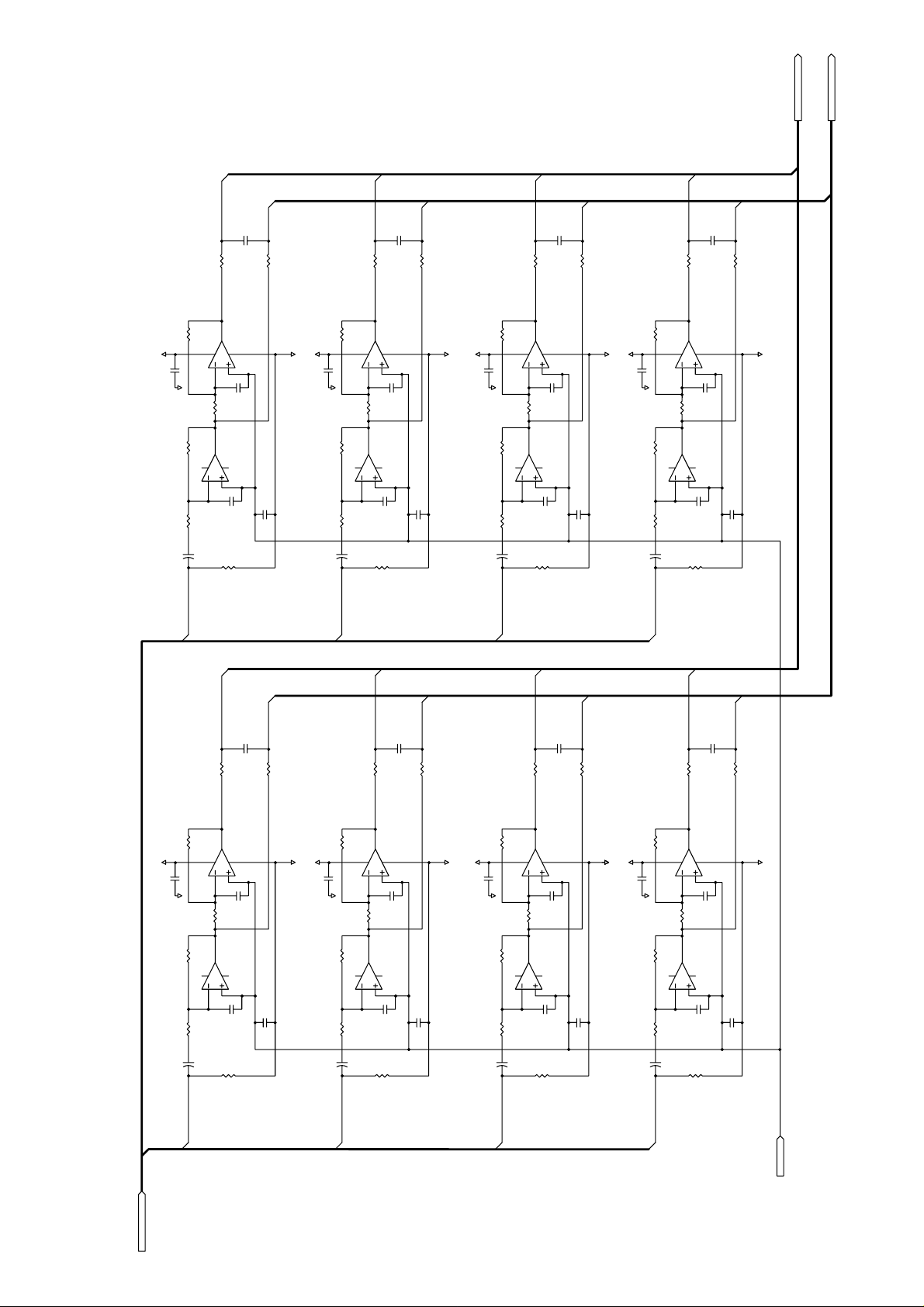
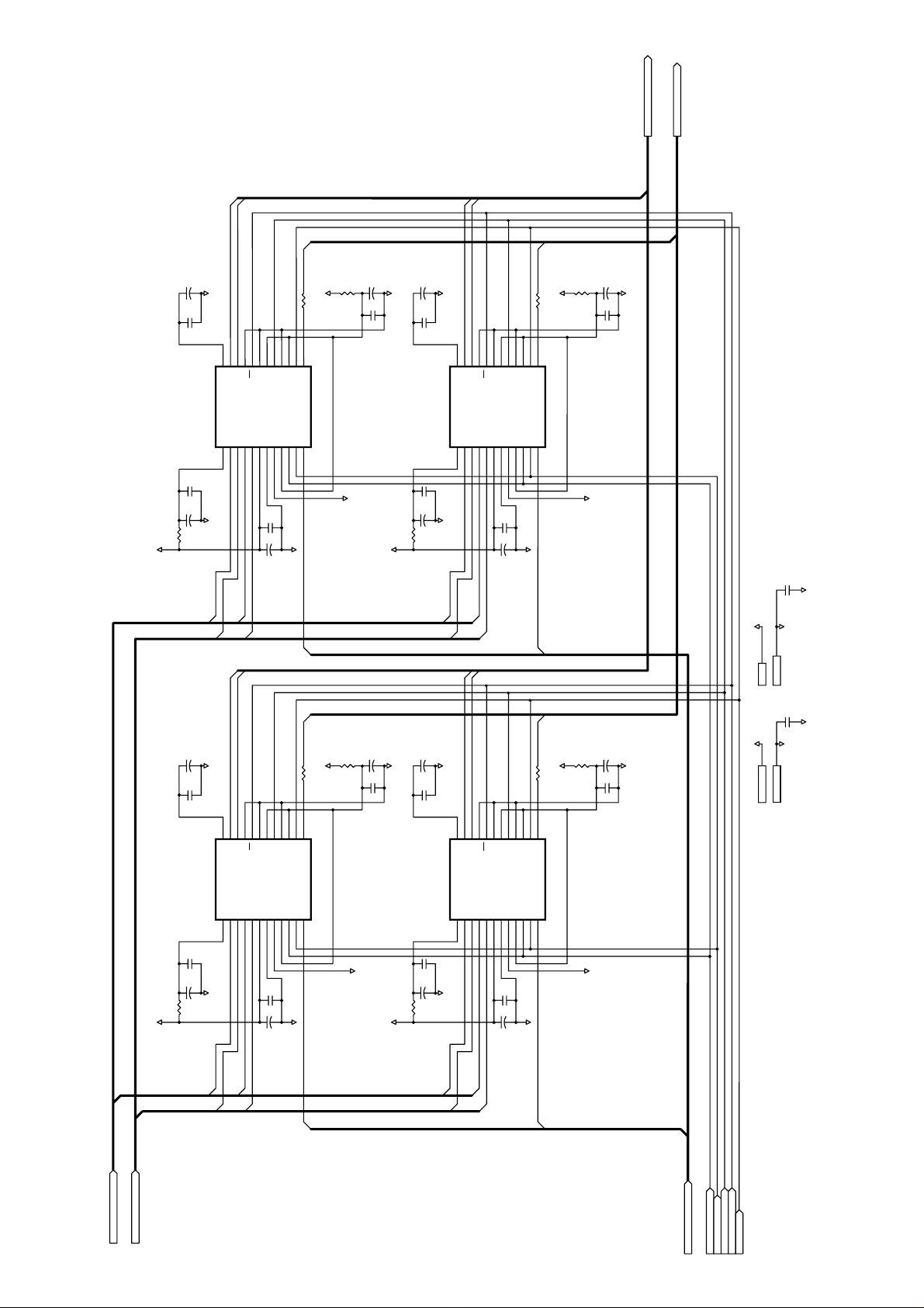
Page 19

-11.5dBV
AOUT+[1..8]
AOUT+[1..8] AOUT+[1..8]
3
2
84
1
AGND
AOUT+1
C111
10/16
U153A
NJM4565M
C115
non
C112
680p
C114
0.01
C113
0.01
C116
100/16
R111
10k
R113
2.2k
R114
100k
AOUT1
R112
12k
A-10
AGND
AGND
AGND
A+10
G=1.5dB
5
6
7
AGND
AOUT+2
C211
10/16
U153B
NJM4565M
C215
non
C212
680p
C216
100/16
R211
10k
R213
2.2k
R214
100k
AOUT2
R212
12k
AGND
3
2
84
1
AGND
AOUT+5
AOUT+6
C511
10/16
U353A
NJM4565M
C515
non
C512
680p
C514
0.01
C313
0.01
C516
100/16
R511
10k
R513
2.2k
R514
100k
AOUT5
AOUT6
R512
12k
A-10
AGND
AGND
AGND
A+10
5
6
7
AGND
C611
10/16
U353B
NJM4565M
C615
non
C612
680p
C616
100/16
R611
10k
R613
2.2k
R614
100k
R612
12k
AGND
3
2
84
1
AGND
AOUT+7
AOUT+8
C711
10/16
U453A
NJM4565M
C715
non
C712
680p
C714
0.01
C413
0.01
C716
100/16
R711
10k
R713
2.2k
R714
100k
AOUT7
AOUT8
R712
12k
A-10
AGND
AGND
AGND
A+10
5
6
7
AGND
C811
10/16
U453B
NJM4565M
C815
non
C812
680p
C816
100/16
R811
10k
R813
2.2k
R814
100k
R812
12k
AGND
3
2
84
1
AGND
AOUT+3
C311
10/16
U253A
NJM4565M
C315
non
C312
680p
C314
0.01
C213
0.01
C316
100/16
R311
10k
R313
2.2k
R314
100k
AOUT3
R312
12k
A-10
AGND
AGND
AGND
A+10
5
6
7
AGND
AOUT+4
C411
10/16
U353B
NJM4565M
C415
non
C412
680p
C416
100/16
R411
10k
R413
2.2k
R414
100k
AOUT4
R412
12k
AGND
AGND
A+10
C65
47/16
AOUT[1..8] AOUT[1..8]
AOUT[1..8]
-10dBV
VC-8
• AD-DA OUT
19
Page 20

FOSTEX CORPORATION 3-2-35 Musashino, Akishima, Tokyo, Japan 196-0021
FOSTEX CORPORATION OF AMERICA 15431 Blackburn Ave., Norwalk, CA 90650, U.S.A.
© PRINTED IN JAPAN JUN 1999 8288784000
 Loading...