

Fostex UR-2 Owners Manual
POWER
Model UR-2
STEREO RACK MEMORY RECORDER
PLAY
SHIFT
MODE
PHONES
USB
USBPC
(KYBD ONLY)
MIN
MAX
HOST
SD-1 SD-2
AUTO PLAY
EJECT
READY
SD-1
SD-2
EDIT
REPEAT
FILE SEL DISPLAY
STRG SEL
TIME
STEREO RACK MEMORY RECORDER
REC RDY
REC
UR-2
EXIT
MRGN RST
STOP
ABS 0
REC END
MENU / ENTER
PLAY
FILE/CURSOR
CUEPREV NEXT
REW
CUE/LOCATE MIC IN
F FWD
MIN
TIME EDIT
MAX
8289647000
(480799)
PHANTOM
MIC SET
MIN
MAX
MIC GAIN MIC ININPUT LEVEL
Owner’ s Man ual
Model UR-2
CAUTION
RISK OF ELECTRIC SHOCK
DO NOT OPEN
CAUTION: TO REDUCE THE RISK OF ELECTRIC SHOCK,
DO NOT REMOVE COVER (OR BACK).
NO USER - SERVICEABLE PARTS INSIDE.
REFER SERVICING TO QUALIFIED SERVICE PERSONNEL.
"WARNING"
"TO REDUCE THE RISK OF FIRE OR ELECTRIC
SHOCK, DO NOT EXPOSE THIS APPLIANCE TO RAIN
OR MOISTURE."
SAFETY INSTRUCTIONS
1. Read Instructions - All the safety and operating instructions
should be read before the appliance is operated.
2. Retain Instructions - The safety and operating instructions
should be retained for future reference.
3. Heed Warnings - All warnings on the appliance and in the
operating instructions should be adhered to.
4. Follow Instructions - All operating and use instructions should
be followed.
5. Water and Moisture - The appliance should not be used near
water - for example, near a bathtub, washbowl, kitchen sink,
laundry tub, in a wet basement, or near a swimming pool, and
the like.
6. Carts and Stands - The appliance should be used only with a
cart or stand that is recommended by the manufacturer.
An appliance and cart combination should be moved with care.
Quick stops, excessive force, and uneven surfaces may cause
the appliance and cart combination to overturn.
7. Wall or Ceiling Mounting - The appliance should be mounted
to a wall or ceiling only as recommended by the manufacturer.
8. Ventilation - The appliance should be situated so that its location
or position dose not interfere with its proper ventilation.
For example, the appliance should not be situated on a bed,
sofa, rug, or similar surface that may block the ventilation
openings; or, placed in a built-in installation, such as a bookcase
or cabinet that may impede the flow of air through the ventilation
openings.
9. Heat - The appliance should be situated away from heat sources
such as radiators, heat registers, stoves, or other appliances
(including amplifiers) that produce heat.
10. Power Sources - The appliance should be connected to a power
supply only of the type described in the operating instructions
or as marked on the appliance.
11. Grounding or Polarization - The precautions that should be
taken so that the grounding or polarization means of an
appliance is not defeated.
CAUTION:
TO PREVENT ELECTRIC SHOCK, MATCH WIDE
BLADE OF PLUG TO WIDE SLOT, FULLY INSERT.
ATTENTION:
POUR EVITER LES CHOCS ELECTRIQUES,
INTRODUIRE LA LAME LA PLUS LARGE DE LA FICHE
DANS LA BORNE CORRESPONDANTE DE LA PRISE
ET POUSSER JUSQU' AU FOND.
The lightning flash with arrowhead symbol, within an
equilateral triangle, is intended to alert the user to the
presence of uninsulated "dangerous voltage" within the
product's enclosure that may be of sufficient magnitude
to constitute a risk of electric shock to persons.
The exclamation point within an equilateral triangle is
intended to alert the user to the presence of important
operating and maintenance (servicing) instructions in the
literature accompanying the appliance.
12. Power Cord Protection - Power supply cords should be routed
so that they are not likely to be walked on or pinched by items
placed upon or against them, paying particular attention to cords
at plugs, convenience receptacles, and the point where they
exit from the appliance.
13. Cleaning - The appliance should be cleaned only as
recommended by the manufacturer.
14. Nonuse Periods - The power cord of the appliance should be
unplugged from the outlet when left unused for a long period of
time.
15. Object and Liquid Entry - Care should be taken so that objects
do not fall and liquids are not spilled into the enclosure through
openings.
16. Damage Requiring Service - The appliance should be serviced
by qualified service personnel when:
A. The power supply cord or the plug has been damaged; or
B. Objects have fallen, or liquid has been spilled into the appliance;
or
C. The appliance has been exposed to rain; or
D. The appliance does not appear to operate normally or exhibits
a marked change in performance; or
E. The appliance has been dropped, or the enclosure damaged.
17. Servicing - The user should not attempt to service the appliance
beyond that described in the operating instructions.
All other servicing should be referred to qualified service
personnel.
18. The appliance should be situated away from drops of water or
spray of water.
19. Objects containing liquid such as vase must not be put on the
appliance.
20. The appliance is not completely isolated from the power supply
even if the power switch is at off position.
21. Apparatus shall not be exposed to dripping or splashing and
no objects filled with liquids, such as vases, shall be placed on
the apparatus.
22. Only use attachments/accessories specified by the
manufacturer.
23. An appliance with a protective earth terminal should be
connected to a mains outlet with a protective earth connection.
24. An appliance should be placed in a position where an AC plug
/ inlet can be easily pulled out by hand.
25. Main plug is used as the disconnection device. It shall remain
readily operable and should not be obstructed during intended
use. To be completely disconnected the apparatus from supply
mains, the mains plug of the apparatus shall be disconnected
from the mains socket outlet completely.
-2-
Important Safety Instructions
Model UR-2
1) Read these instructions.
2) Keep these instructions.
3) Heed all warnings.
4) Follow all instructions.
5) Do not use this apparatus near water.
6) Clean only with dry cloth.
7) Do not block any ventilation openings.
Install in accordance with the
manufacturer's instructions.
8) Do not install near any heat sources such
as radiators, heat registers, stoves, or
other apparatus (including amplifiers) that
produce heat.
9) Do not defeat the safety purpose of the
polarized or grounding-type plug.
A polarized plug has two blades with one
wider than the other. A grounding type
plug has two blades and a third grounding
prong. The wide blade or the third prong
are provided for your safety.
If the provided plug does not fit into your
outlet, consult an electrician for
replacement of the obsolete outlet.
11) Only use attachments/accessories
specified by the manufacturer.
12) Use only with the cart, stand, tripod,
bracket, or table specified by the
manufacturer, or sold with the apparatus.
When a cart is used, use caution when
moving the cart/apparatus combination
to avoid injury from tip-over.
13) Unplug this apparatus during lightning
storms or when unused for long periods
of time.
14) Refer all servicing to qualified service
personnel. Servicing is required when the
apparatus has been damaged in any
way, such as power-supply cord or plug
is damaged, liquid has been spilled or
objects have fallen into the apparatus, the
apparatus has been exposed to rain or
moisture, does not operate normally, or
has been dropped.
10) Protect the power cord from being walked
on or pinched particularly at plugs,
convenience receptacles, and the point
where they exit from the apparatus.
-3-

Model UR-2
Safety Instructions .............................................................................................................. 2
Introduction
Precaution ................................................................................................................................10
Precautions on installation ....................................................................................................10
About storage devices ............................................................................................................11
Formatting of a storage device ..............................................................................................11
About version upgrade ...........................................................................................................11
Notes on moisture condensation .........................................................................................11
Overview
Table of contents
Main features ............................................................................................................................12
Names and functions
Front panel ................................................................................................................................13
Rear panel .................................................................................................................................16
Screen details ..........................................................................................................................17
Home screen in stop or playback mode .................................................................................17
Home screen in record or input monitor mode ......................................................................18
Screens in MENU mode ........................................................................................................19
Other screens .........................................................................................................................20
Preparation
Connection to external devices (fr om the front panel ) ......................................................21
Connection to headphones ....................................................................................................21
Connection to a computer ......................................................................................................21
Connection to a USB keyboard ..............................................................................................21
Connection to an external microphone ..................................................................................21
Connection to external devices (from the rear panel) ........................................................22
Analog audio connection .......................................................................................................22
Digital audio connection .........................................................................................................22
-4-

Model UR-2
Foot switch connection ..........................................................................................................22
Pow er connection ..................................................................................................................22
RS232C connection ..............................................................................................................22
Parallel remote connection .................................................................................................... 22
T urning on the power ..............................................................................................................23
Setting the internal clock .......................................................................................................23
Adjusting the display ..............................................................................................................24
Adjusting the brightness of the display ..................................................................................24
Inversing the display ..............................................................................................................24
Enlarging the file name display ..............................................................................................25
Inserting a storage device .....................................................................................................26
Removing a storage device ...................................................................................................27
Selecting a storage device .....................................................................................................28
Basic knowledge about folders and files on a storage de vice .........................................29
Recording
Recording system ...................................................................................................................29
Recording time ........................................................................................................................29
Setup before you start recording ..........................................................................................29
SYSTEM SETUP menu item ..................................................................................................30
Default file name ....................................................................................................................30
Recording source ..................................................................................................................30
Sampling frequency/Quantization bit ....................................................................................30
Recording channels ..............................................................................................................30
Maximum file size ..................................................................................................................30
Peak hold time .......................................................................................................................30
Reference lev el ......................................................................................................................30
MIC IN SETUP menu item .......................................................................................................31
Enabling/disabling the [MIC IN] ke y .......................................................................................31
[MIC IN] key function ..............................................................................................................31
Enabling/disabling [MIC IN] ke y during recording .................................................................31
Phantom power on/off ...........................................................................................................31
Basic recording ............................................................................................................... ........32
Inserting a storage device .....................................................................................................32
-5-

Model UR-2
Setting a CUE point .................................................................................................................35
Adjusting the recording level ................................................................................................. .32
When recording a digital source ..........................................................................33
When recording a microphone source ......................................................................33
Checking the remaining time .................................................................................................33
Start recording .......................................................................................................................34
Setting a CUE point on-the-fly during recording ...................................................................35
Viewing CUE points ............................................................................................................ ...35
Editing a CUE point ........................................................................................................... .....36
Editing a CUE label ....................................................................................................36
Editing CUE time data ................................................................................................36
Deleting a CUE point ..................................................................................................36
Setting a new CUE point using the CUE LIST screen ..........................................................37
Using an external microphone
Using a microphone for recor ding .......................................................................................38
Using a microphone during playbac k ..................................................................................38
Setting in the MIC IN SETUP menu .......................................................................................39
Enabling/disabling the [MIC IN] ke y ......................................................................................39
[MIC IN] key function ..............................................................................................................39
Attenuating playback le vel .................................................................................................... .40
Enabling/disabling the [MIC IN] ke y during recording ...........................................................40
Phantom power on/off ...........................................................................................................40
Playback
Play mode ................................................................................................................................41
Playback in SINGLE pla y mode ............................................................................................41
Selecting a playback file ........................................................................................................42
Using the [ ] and [ ] k eys ................................................................................42
Using the file selection screen ...................................................................................42
Playback in ALL pla y mode ...................................................................................................43
Playback in RELAY play mode ..............................................................................................43
Playback in CHAIN SINGLE pla y mode ...............................................................................44
Playback in CHAIN ALL pla y mode ......................................................................................44
-6-

Model UR-2
Playback in MEMOR Y play mode .........................................................................................45
Playback in TIMER pla y mode ...............................................................................................46
Creating the chain play list ....................................................................................................46
Editing the chain play list .......................................................................................................47
Editing a point using the time edit function ............................................................................47
Replacing a point with CUE time ...........................................................................................48
Fine-adjusting using digital scrub ..........................................................................................49
Inserting a file to the list ..........................................................................................................49
Deleting a file from the chain play list .....................................................................................50
Creating the timer play list .................................................................................................. ...51
Editing the timer play list ........................................................................................................52
Changing a file .......................................................................................................................52
Editing the time and days of the week ...................................................................................53
Editing the playback area of a file (Using the time edit function) ...........................................53
Editing the playback area of a file (Replacing with a CUE time) ...........................................53
Cueing function .......................................................................................................................54
Repeat function .......................................................................................................................54
Auto play function ...................................................................................................................54
Power on pla y function ...........................................................................................................54
Digital scrub function .............................................................................................................55
PLA Y SETUP menu details ....................................................................................................56
Play mode setting ..................................................................................................................56
Repeat function .....................................................................................................................57
Auto play function ..................................................................................................................57
Pow er on play function ........................................................................................................ ...58
Mono mix function .................................................................................................................58
Locate / skip
Skipping among files ..............................................................................................................59
Skipping among CUE points .................................................................................................59
Locating the beginning of a file .............................................................................................60
Locating the end of a file ........................................................................................................60
Locating a CUE point ..............................................................................................................60
Locating a position by specifying the time .........................................................................60
Direct locate using the numeric keys ...................................................................................60
-7-

Model UR-2
Controlling from an e xternal de vice
Setting REMOTE SET menu ..................................................................................................61
Using [P ARALLEL REMOTE] connector .............................................................................61
Using [FOOT SW] jac k ............................................................................................................62
Setting “Foot SW . Mode” ........................................................................................................62
Using the [RS232C] port ........................................................................................................63
Setting “RS232C Setup” menu .............................................................................................63
Command control list .............................................................................................................64
File transfer between the unit and your computer
Connecting a computer to the unit .......................................................................................65
Copying a file to a computer ..................................................................................................66
Copying a file from a computer .............................................................................................66
Using a USB keyboard
Keys on a keyboar d and assigned functions ......................................................................67
Function keys on a USB ke yboard ........................................................................................67
Control keys on a USB ke yboard ..........................................................................................68
Shortcut keys on a USB keyboard ........................................................................................68
Other keys on a USB ke yboard .............................................................................................68
Keys on a n umeric keyboard .................................................................................................68
Upgrading the UR-2
Executing upgrade file ...........................................................................................................69
MENU mode
About MENU mode .................................................................................................................70
SYSTEM SETUP menu details ..............................................................................................71
Basic operation of SYSTEM SETUP menu .........................................................................72
Setting a file name .................................................................................................................73
Selecting the input source .....................................................................................................74
Selecting the FS and bit ...................................................................................................... ...74
Selecting stereo or mono recording mode ............................................................................75
-8-

Model UR-2
Setting the maximum file length ............................................................................................75
Setting the peak hold time .....................................................................................................76
Setting the reference lev el .....................................................................................................76
Setting cue monitor output destination ..................................................................................77
Setting the output digital signal format ..................................................................................77
Setting the USB keyboard type .............................................................................................78
Saving system memory data ................................................................................................78
Loading the system memory data .........................................................................................79
Initializing the setup data .......................................................................................................80
Initializing flash memory ........................................................................................................80
Checking the system version ................................................................................................81
STORA GE UTILITY menu details ..........................................................................................82
Basic operation of STORA GE UTILITY menu .....................................................................82
Editing a file name .................................................................................................................83
Viewing the file information .................................................................................................. ..83
Copying files ..........................................................................................................................84
Deleting a file .........................................................................................................................85
Erasing all data on the storage device ...................................................................................86
Editing the volume label .........................................................................................................87
Creating a file information file in CSV format .........................................................................87
Chain play list / Timer play list (e xamples) ...........................................................................88
Main specifications
Inputs/outputs ................................................................................................................ .........89
Recording/playbac k ...............................................................................................................89
General .....................................................................................................................................90
Physical dimensions ........................................................................................................... ...90
Index .........................................................................................................................................91
Declaration of EC Directive ...................................................................................................92
For the US Customers Only (Fostex America Limited W arranty ) ....................................93
-9-
Model UR-2 <Introduction / Overview>
PHONES
MAX
MIN
MAX
MIN
MAX
MIN
MIC GAIN MIC ININPUT LEVEL
ABS 0
REC END
POWER
USB
(KYBD ONLY)
READY
EJECT
SHIFT
MODE
PLAY
TIME
REC RDY
EXIT
EDIT
REPEAT
CUE/LOCATE MIC IN
PHANTOM
MIC SET
FILE SEL DISPLAY
FILE/CURSOR
MENU / ENTER
REC
STOP
PLAY
REW
F FWD
MRGN RST
STRG SEL
SD-2
USBPC
HOST
SD-1
AUTO PLAY
CUEPREV NEXT
TIME EDIT
UR-2
STEREO RACK MEMORY RECORDER
SD-1 SD-2
Introduction
Thank you very much for purchasing the
Model UR-2 recorder. Read this manual and
follow all instructions before using this unit,
and retain it for future reference.
Precautions
• You can supply the power either from the
dedicated Fostex AC adaptor or external
battery. When you use an external battery, be
sure that the battery can stably supply the
rated power voltage.
• While the unit is accessing a storage device
(an SD card or USB memory) (i.e. during
recording or playback), do not turn off the
power or remove the device.
Otherwise, recorded data may be lost or the
storage device may be damaged. Make sure
that the unit completely stops accessing the
storage device and the access indicator is
unlit before you remove the device.
• Do not let water or other liquid, or metal
objects such as pins, accidentally enter the
inside of the unit because this may lead to
electric shock or damage. Should water enter
the inside of the unit, turn off the power,
unplug the AC adaptor, and consult your
dealer or the nearest FOSTEX service station.
Precautions on installation
• Do not install the unit in the following
conditions.
* In an extremely hot or cold place
* In a moist place
* In a vibrated place
* In a dusty place
* In a strong magnetic field or near a device
which generates a magnetic field
* In the direct sunshine
* In the direct shower or rain
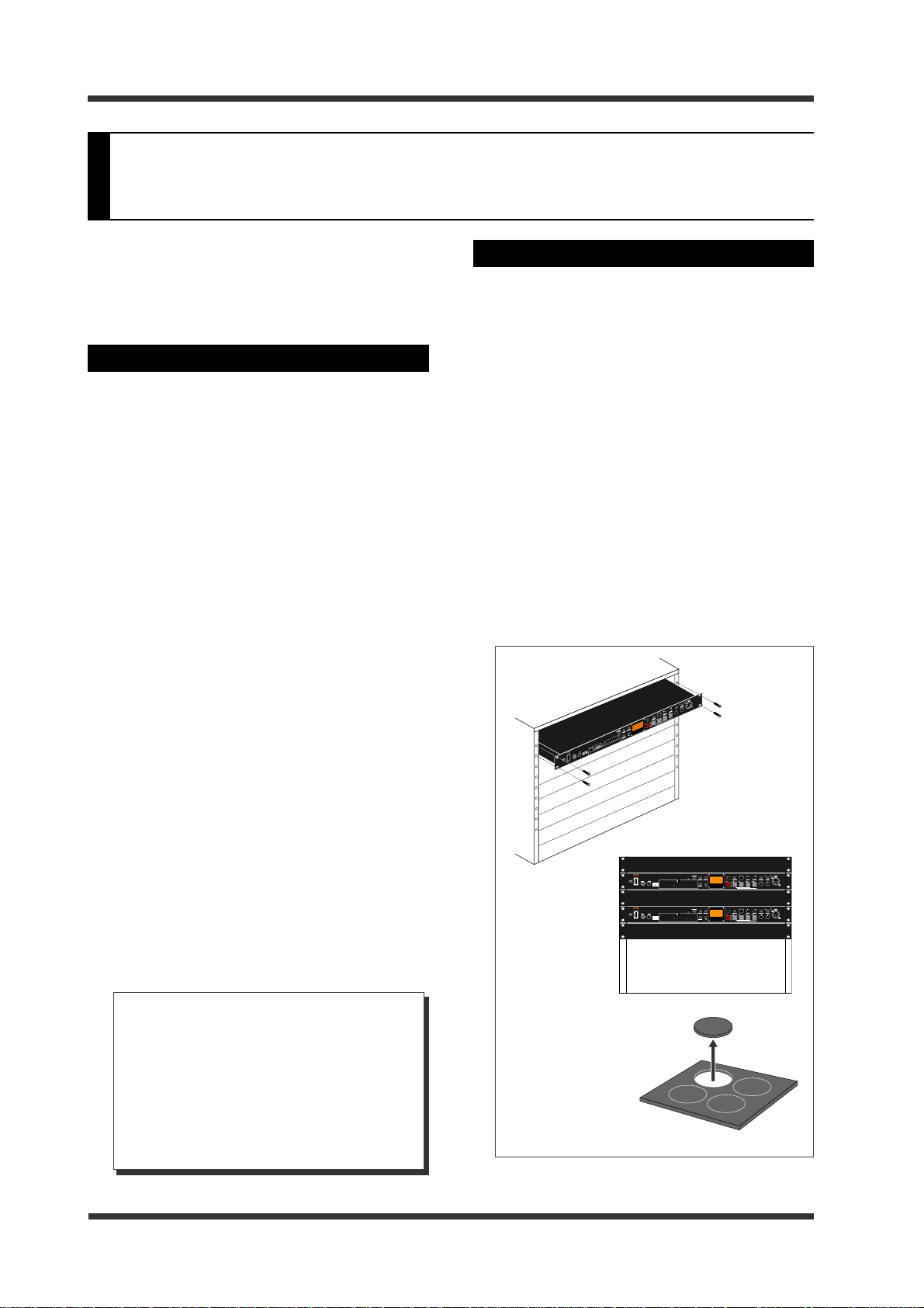
• When you mount the unit to an EIA rack, use
the appropriate mounting screws (note that
the mounting screws are not supplied with the
unit).
It is recommended to leave at least one empty
rack space above and below the unit for
reducing the amount of heat transferred.
PHANTOM
CUE MIC IN
MIC SET
FILE/CURSOR
MAX
MIN
F FWD
CUEPREV NEXT
MENU / ENTER
MIC GAIN MIC ININPUT LEVEL
MAX
MIN
REW
EXIT
PLAY
REC RDY
MRGN RST
STOP
REC
ABS 0
REC END
TIME
PLAY
MODE
REPEAT
UR-2
SHIFT
EDIT
DISPLAY
STEREO RACK MEMORY RECORDER
FILE SEL
AUTO PLAY
EJECT
READY
STRG SEL
SD-2
SD-1
HOST
USBPC
USB
(KYBD ONLY)
POWER
PHONES
MAX
MIN
• Do not drop the unit or give it a strong shock.
Doing so may damage the internal circuits,
display or panels. Handle the unit with great
care because it is a precision mechanical
device.
• Do not open the case or touch inside the unit
because of the danger of electric shock and
failure.
<About replacing the lithium battery>
The unit contains the internal lithium battery for running the internal clock. The
battery should be replaced approximately
every five years. To replace the battery,
ask your dealer or the nearest FOSTEX service station. If the battery is not correctly
Put the supplied
rubber feet on the
bottom of the unit
for slip-proof if
required.
replaced, there may be a risk of explosion,
etc.
-10-
Model UR-2 <Introduction / Overview>
About storage devices
The unit uses an SD card (SDHC supported) or
USB memory as a storage device for recording
and playback.
It supports both FAT 16 and FAT 32 file formats.
For an SD card, the maximum recording capacity is 32 GB, while the minimum recording capacity is 128 MB. For a USB memory, the maximum recording capacity is not limited.
You can use any SD card or USB memory which
is FAT 16/32 formatted.
<Note>:
ibility problem between the unit and the
controller on a USB memory, the unit may
not recognize the USB memory or recording may become unstable.
<Note>:
an SD card or USB memory used for recording and playback of the unit as a "storage
device".
Please note that due to a compat-
In this manual, we sometimes call
About version upgrade
The software of the unit may be upgraded with
the feature/function enhancement.
You can check the latest software version information via the Fostex website (http://
www.fostex.com) or your nearest Fostex service
station.
You can download the upgrade via the Fostex
website and upgrade the unit by yourself. See
page 69 of this manual for details.
Notes on moisture condensation
When you bring the unit from a cold place to a
warm place, moisture may condense on the drive,
display, panels, etc. In such a case, leave the unit
for a while until it warms up and evaporates any
moisture.
Formatting of a storage device
After you buy a new storage device (an SD (SDHC)
card or USB memory), you do not need to format
it before using with the unit.
However an SD (SDHC) card which has been formatted using a formatting software for a computer cannot be used with the unit (though a USB
memory which has been formatted using a formatting software for a computer can be used with
the unit).
To use such an SD (SDHC) card with the unit,
download the software (freeware) from the SD
Association website (see URL below) and format
the card using it. This software formats an SD
(SDHC) card to conform to the SD or SDHC specification (see the SD Association website for details).
http://www.sdcard.org/about/downloads/
-11-

Model UR-2 <Introduction / Overview>
Overview
Main features
• You can make stereo or mono recording/
playback of the WAV (BWF) file using an SD
card or USB memory.
•␣ You can make recording at "16-bit, 44.1 or
48 kHz" or "24-bit, 44.1, 48, 88.2 or 96 kHz".
• A USB 2.0 port is provided for high-speed file
transfer between a computer and the UR-2.
• The unit is equipped with two SD card slots
and a USB port ([USB-HOST]) dedicated for a
USB memory. You can record a file to an SD
card or a USB memory. You can even make
continuous playback over storage devices.
Note that you cannot use a USB memory while
a computer is connected to the [USB-PC] port.
• Supporting the FAT file format, you can use
an SD card or a USB memory which has been
used with the unit to a computer.
• Comprehensive playback functions including
chain play and memory play allow you to use
the unit in various circumstances.
• In addition to the balanced (XLR) and
unbalanced (RCA) analog inputs/outputs, the
unit provides the digital input and output
(XLR) ports.
• The organic electroluminescence display
provides high level of visibility including wide
viewing angle and high contract.
• Supports external controls via the footswitch,
parallel remote (D-sub 25-pin connector) and
RS232C (D-sub 9-pin connector).
• A dedicated USB port for a USB keyboard is
provided. You can edit a file name as well as
control the transport from a USB keyboard.
• By adopting DC power supply, you can
supply power from an external battery as well
as from the AC adaptor.
This is a great advantage for outdoor event or
location recording.
•␣ By installing the optional MIDI port (available
soon), you can use MMC and MTC.
• Functions such as timer play or power-on play
are useful for an audio installation system.
You can ring a chime or broadcast a regular
announcement.
• Each play mode list can be created in the form
of CSV format, allowing editing easily using a
text editor or a spreadsheet software on PC.
• When creating the chain play list, you can
fine-adjust the start and end points by
checking the waveform on the display using
the digital scrub function.
• A microphone input connector supporting the
+48 V phantom power is provided on the front
panel. Not only you can record a microphone
source, but also you can mix an
announcement from the microphone with the
playback sound.
-12-
Model UR-2 <Names and functions>
Names and functions
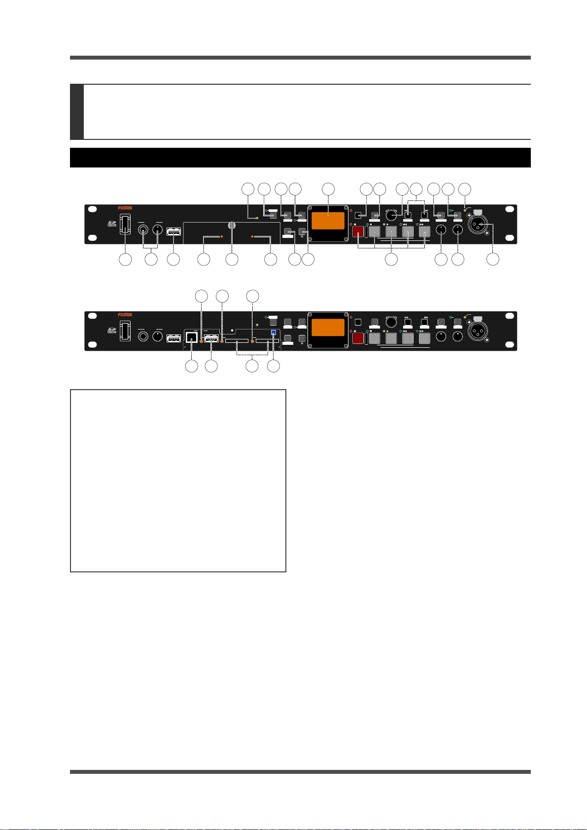
Front panel
When the slot protection panel
is fitted
POWER
POWER
PHONES
USB
(KYBD ONLY)
MIN
MAX
2
1
PHONES
3
USB
(KYBD ONLY)
MIN
MAX
USBPC
HOST
45
29
USBPC
HOST
28 27
24
SD-1
SD-1 SD-2
4
SD-1
AUTO PLAY
6
AUTO PLAY
26
About Non-shift mode and Shift mode
*Some keys have the secondary function which
is available when the SHIFT indicator is lit (i.e.
in the Shift mode), while the primary function
is available when the SHIFT indicator is unlit
(i.e. in the Non-shift mode).
The secondary function is called "Shift function"
and printed under a key on the white background. When you turn on the power, the unit
boots up in the Non-shift mode.
In this manual, we sometimes say "when
SHIFTed" and "when unSHIFTed", instead of
"when the SHIFT indicator is lit" (or "in the Shift
mode") and "when the SHIFT indicator is unlit"
(or "in the Non-shift mode") respectively.
1) [POWER] switc h
Turns on or off the power of the unit.
2) [PHONES] jack, [PHONES] contr ol
You can connect a stereo headphones plug to
the [PHONES] jack and control the headphones
volume using the [PHONES] control.
3) [USB (KYBD ONLY)] port
This port is used for connecting a USB keyboard.
When you use a USB keyboard, set the keyboard
type (US or JAPAN) appropriately using the
“Keyboard type” menu item in the “SYSTEM
SETUP” menu of the MENU mode (see page 78
for details).
22
READY
READY
21
PLAY
SHIFT
MODE
EDIT
EJECT
FILE SEL DISPLAY
STRG SEL
78
6
TIME
REPEAT
STEREO RACK MEMORY RECORDER
20
UR-2
REC RDY
19
EXIT
MRGN RST
REC
STOP
ABS 0
REC END
When the slot protection panel is not fitted
PLAY
SHIFT
MODE
TIME
EDIT
EJECT
REPEAT
FILE SEL DISPLAY
STRG SEL
UR-2
STEREO RACK MEMORY RECORDER
REC RDY
EXIT
MRGN RST
REC
STOP
ABS 0
REC END
MENU / ENTER
PLAY
9
MENU / ENTER
PLAY
16
1718
FILE/CURSOR
REW
FILE/CURSOR
REW
CUEPREV NEXT
CUEPREV NEXT
1415
13
PHANTOM
MIC IN
CUE/LOCATE
MIC SET
TIME EDIT
F FWD
MIN
MIN
MAX
MAX
MIC GAIN MIC ININPUT LEVEL
11
10
CUE/LOCATE
MIC IN
TIME EDIT
F FWD
MIC SET
MIN
MIN
MAX
MIC GAIN MIC ININPUT LEVEL
12
PHANTOM
MAX
23
SD-2
SD-2
25
4) [SD-1] indicator
Indicates the condition of the SD card inserted
on the [SD-1] slot. You can see the indicator
regardless of whether or not the slot protection
panel is fitted.
• Lit in orange: The unit is reading data.
• Lit in red: The unit is writing data.
• Lit in green: The unit is not accessing the SD
card.
• Unlit: No SD card is inserted or the unit is in
sleep mode.
5) Fixing screw for the slot protection panel
The protection panel protects the card slots and
USB port for the storage devices.
To access the slot/port, loosen the fixing screw
and open the slot protection panel (see page 26
for details).
6) [SD-2] indicator
Indicates the condition of the SD card inserted
on the [SD-2] slot.
You can see the indicator regardless of whether
or not the slot protection panel is fitted.
See [SD-1] indicator above for the indicator
status.
7) [FILE SEL] / [STRG SEL] key
This key has primary (unSHIFTed) and secondary (SHIFTed) functions.
When unSHIFTed:
Pressing this key enters the file select mode
(see page 42).
-13-
Model UR-2 <Names and functions>
When SHIFTed:
Pressing this key enters the storage select mode
(see page 28).
8) [DISPLAY] / [ ] key
This key has primary (unSHIFTed) and secondary (SHIFTed) functions.
When unSHIFTed:
Pressing this key switches the display mode (see
page 25).
When SHIFTed:
Pressing this key enters the display brightness
control mode (see page 24).
9) Transport control key
PLAY] key
[
Pressing this key starts playback.
Pressing this key while holding down the [STOP]
key starts digital scrubbing (see page 55).
[ REC] key
Pressing this key while the [REC RDY] indicator
is lit starts recording (see page 35).
[ STOP] key
Pressing this key stops playback or recording.
When the unit is stopped, pressing the [REW]
or [F FWD] key while pressing down this key
skips to the beginning or the last recording position of the current file.
[ REW] key
Pressing this key while stopped starts fastrewind at up to 30 times the normal playback
speed. Pressing this key during playback executes backward cueing playback (see page 54).
While stopped, pressing this key while holding
down the [STOP] key skips to the beginning (ABS
0) of the current file (see page 60).
[ F FWD] key
Pressing this key while stopped starts fastforward at up to 30 times the normal playback
speed. Pressing this key during playback executes forward cueing playback (see page 54).
While stopped, pressing this key while holding
down the [STOP] key skips to the last recording
position of the current file (see page 60).
10) [INPUT LEVEL] control
Adjusts the input level of analog signals fed to
the [ANALOG INPUT] connectors (see page 33).
You can check and adjust the input level in the
input monitor mode.
11) [MIC GAIN] control
Adjusts the input gain of an external microphone signal fed to the [MIC IN] connector on
the front panel.
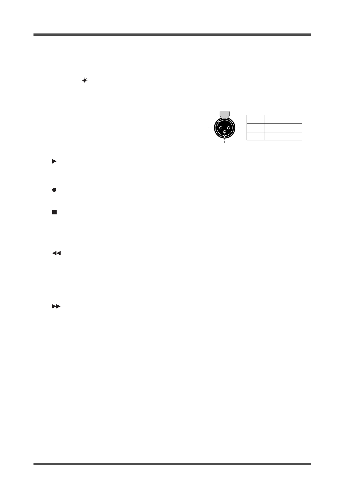
12) [MIC IN] connector
Connects an external microphone.
By turning on the [MIC IN] indicator by pressing the [MIC IN] key, you can make recording
using an external microphone as well as can mix
playback signal of a file playback and an
external microphone signal.
You can supply the phantom power to the
[MIC IN] connector (see page 40).
1
2
2
1
3
GND
HOT
COLD
3
13) [PHANTOM] indicator
By setting the "Phantom" menu item in the MIC
IN SETUP menu of the MENU mode to "On", the
phantom power is supplied to the [MIC IN]
connector and this indicator is lit (see page 40).
14) [MIC IN] / [MIC IN] indicator, [MIC SET] key
This key has primary (unSHIFTed) and secondary (SHIFTed) functions.
When unSHIFTed:
Pressing this key switches on or off the microphone input.
When on, the indicator lights up. When off, it is
unlit (see page 34).
If you press this key to switch on the microphone input during recording, the microphone
input takes priority and you can starts microphone recording (see pages 34 and 38).
If you switch on the microphone input during
playback, you can mix the microphone signal
to the playback signal (see pages 38 and 42).
When SHIFTed:
Pressing this key enters the MIC IN SETUP menu
of the MENU mode. In this menu, you can make
settings for using an external microphone. (see
page 39).
15) [CUE/LOCATE] / [TIME EDIT] key
This key has primary (unSHIFTed) and secondary (SHIFTed) functions.
When unSHIFTed:
During recording, pressing this key sets a CUE
mark at the current position on-the-fly (see page
35).
While stopped or during playback, pressing this
key brings up the CUE list. While the list is
shown, you can skip to the desired CUE mark or
edit the CUE label and time data (see page 35).
When SHIFTed:
Pressing this key enters the time edit mode.
Pressing this key again after editing the time
locates the edited time position (see page 60).
-14-
Model UR-2 <Names and functions>
16) [ FILE/CURSOR ] key,
PREV
[
These keys have primary (unSHIFTed) and secondary (SHIFTed) functions.
CUE
NEXT
] keys
When unSHIFTed:
Pressing the key skips to the beginning of the
previous or next file (see page 59).
While the display shows a file name entry screen
in the MENU mode, pressing the key moves the
cursor position.
When SHIFTed:
Pressing the key skips to the previous or next
CUE point (see page 59).
17) [MENU] dial / [ENTER] key
This knob has dual functions: the [MENU] dial
for selecting an option and the [ENTER] key for
confirming the selection.
[ENTER] key function:
Pressing the [ENTER] key while stopped enters
the MENU mode (see page 70).
[MENU] dial function:
In the MENU mode, rotating the [MENU] dial
selects the menu item, selects an alphanumerical
character, etc.
18) [EXIT] / [
This key has primary (unSHIFTed) and secondary (SHIFTed) functions.
MRGN RST
] key
When unSHIFTed:
Pressing this key exits the MENU mode or
cancels setting operation.
When SHIFTed:
In the input monitor mode or during recording, pressing this key resets the margin indication which shows remaining margin to the peak
level.
19) [REC RDY] ke y and indicator
Pressing the key switches on or off the input
monitor mode. When on, the indicator starts
flashing. When recording starts, it lights solid
(see page 33).
20) Organic electroluminescence display
Displays the audio level during recording or
playback, time information, etc., as well as a
menu screen (see page 17).
21) [TIME] / [
This key has primary (unSHIFTed) and secondary (SHIFTed) functions.
REPEAT
] key, [
REPEAT
] indicator
When unSHIFTed:
Pressing the key switches the display mode
between the time display and the remain
display on the Home screen (see page 34).
When SHIFTed:
Pressing the key switches the repeat mode on
or off (see page 54).
When the repeat mode is on, the indicator lights.
22) [PLAY MODE] / [
This key has primary (unSHIFTed) and secondary (SHIFTed) functions.
EDIT
] key
When unSHIFTed:
Pressing this key switches the play mode (see
page 41).
When SHIFTed:
Depending on the current play mode, pressing
this key enters the PLAY SETUP menu or CHAIN
PLAY SET menu of the MENU mode.
23) [
SHIFT
] key and indicator
Pressing this key switches between the Shift and
non-shift mode. In the Shift mode, the indicator lights. In the non-shift mode, the indicator
is unlit.
24) [AUT O PLAY] indicator
This indicator lights when the auto play mode
is on. The auto play mode can be set using the
"Auto play" item in the PLAY SETUP menu of
the MENU mode (see page 57).
25) [EJECT READY] key
Press this key before you remove a storage
device (SD card or USB memory) from the slot
when the power is on (see page 27).
26) SD card slots [SD-1] and [SD-2]
You can set an SD card to each slot (see page
26).
27) [USB-HOST] port
This port is used for connecting a USB memory
(see page 26).
28) [USB-PC] port
This port is used for connecting a computer (see
page 27).
<Note>:
You cannot use the [USB-HOST]
and [USB-PC] ports simultaneously.
29) [USB] indicator
Indicates the condition of the USB memory
inserted on the [USB-HOST] port.
• Lit in orange: The unit is reading data.
• Lit in red: The unit is writing data.
• Lit in green: The unit is not accessing the
USB memory.
• Unlit: No USB memory is inserted or the unit
is in sleep mode.
-15-
Model UR-2 <Names and functions>
1
13
1425
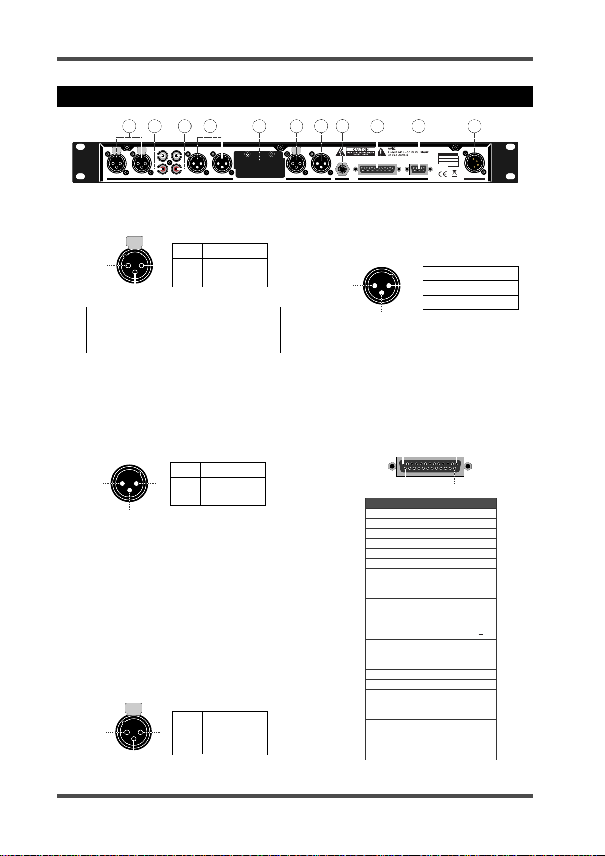
Rear panel
L
R
R
BALANCED [+4dBu]BALANCED [+4dBu]
ANALOG OUTPUT
4
L
5 6
MIDI
1 2 3
LLR
R
UNBALANCED [-10dBV]
ANALOG INPUT
1) [ANALOG INPUT L/R (BALANCED)] connectors
These connectors are the XLR-3-31 type and
accept +4dBu analog signals.
1
2
2
1
3
GND
HOT
COLD
3
<Note>:
unbalanced RCA jack, the balanced input is cut.
2) [ANALOG INPUT L/R (UNBALANCED)] connectors
These connectors are RCA pin jack type and
accept -10 dBV analog signals.
3) [ANALOG OUTPUT L/R (BALANCED)] connectors
These connectors are the XLR-3-32 type and
send +4dBu analog signals.
When a plug is connected to the
7 8
INPUTINPUT
OUTPUTOUTPUT
DIGITAL
FOOT SW
9
REMOTE
RS-232CPARALLEL
10
XLR DC-IN
1:GND
2:HOT
3:COLD
1:GND
2:NC
3:NC
4:12-24V
7) [DIGITAL OUTPUT (BALANCED)] connector
This connector is the XLR-3-31 type and sends
a digital signal conformed to IEC-60958 (AES/
EBU) or IEC-60958 (S/P DIF). The digital output
signal format can be selected via the SYSTEM
SETUP menu of the MENU mode (see page 77).
1
1
2
2
3
3
8) [FOOT SW] jack
By connecting a footswitch or fader start
terminals to this jack, you can start or stop
playback (page 61).
9) [REMOTE PARALLEL] connector
This connector is the D-sub 25 pin type and
used for controlling the unit from an external
device (see page 61).
11
12-24V
DC-IN
GND
HOT
COLD
1
1
2
2
3
GND
HOT
COLD
3
4) [ANALOG OUTPUT L/R (UNBALANCED)] connectors
These connectors are RCA pin jack type and send
-10 dBV analog signals.
5) Blank panel
You can install the optional MIDI IN/OUT board
here (available soon).
6) [DIGITAL INPUT (BALANCED)] connector
This connector is the XLR-3-31 type and accepts
a digital signal conformed to IEC-60958 (AES/
EBU) or IEC-60958 (S/P DIF).
The unit automatically recognizes the digital
signal format.
1
2
1
2
3
GND
HOT
COLD
3
Pin No.
1
2
3
4
5
6
7
8
9
10
11
12
13
14
15
16
17
18
19
20
21
22
23
24
25
Signal IN/OUT
STOP TALL Y
REC T ALLY
STOP
REC
FF (SKIP)
SHIFT
10key-0
10key-2
10key-4
10key-6
10key-8
FOOT SW
GND
PLAY TALLY
+10key IN
PLAY
REC RDY
REW (SKIP)
MIC IN
10key-1
10key-3
10key-5
10key-7
10key-9
VCC (+5V)
OC: Open corrector
OUT (OC)
OUT (OC)
IN
IN
IN
IN
IN
IN
IN
IN
IN
IN
OUT (OC)
IN
IN
IN
IN
IN
IN
IN
IN
IN
-16-
Model UR-2 <Names and functions>
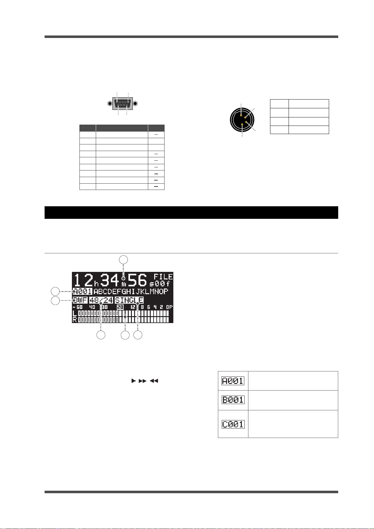
10) [REMOTE RS232C] connector
This RS232C connector is the D-sub 9 pin type
and used for controlling the unit from a
computer, etc. (see page 61).
5
1
69
Pin No. Signal
1
2
3
4
5
6
7
8
9
NC
TX
RX
NC
GND
NC
NC
NC
NC
IN/OUT
OUT
IN
11) [DC-IN] connector
This connector is the XLR-4-32 type and accepts
the DC power from 12 V to 24 V.
Connect the supplied AC adaptor or an
appropriate external battery.
1
2
3
1
2
3
4
4
GND
NC
NC
12-24V
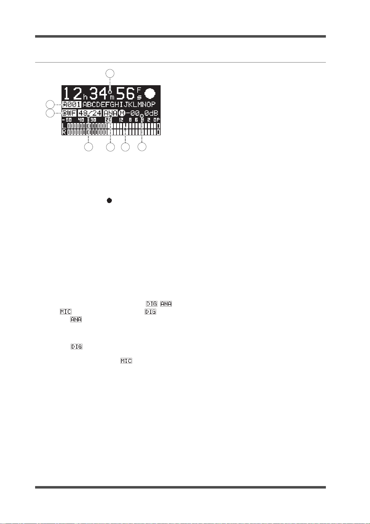
Screen details
When the unit starts up, the Home screen is shown. The Home screen displays the current file information, the level meters and the current status.
Home screen in stop or playback mode
1
6
5
4
1) Time information
While stopped or during playback, the current
playback position is shown.
Pressing the [TIME] key switches between the
time display and the remain display.
Also the appropriate icon ( , , ) which
shows transport status is lit in the top right of
the display during playback, fast forward or
rewind.
2) Play mode
The currently selected play mode is shown (by
default, SINGLE). You can switch the play mode
by pressing the [PLAY MODE] key (see page 41).
2
3
4) Sampling frequency/quantization bit
The Fs and bit information of the current file
(BWF) is displayed.
5) File format
The file format of the current file is displayed.
6) File number/file name
The file number and file name are displayed.
You can edit the file name using the "Edit File
Name" item in the STORAGE UTILITY menu of
the MENU mode (see page 83).
The first alphabetical character in a file
number shows the storage device where the
current file is recorded.
"A" is shown when a file recorded on
an SD card set to SD-1 is loaded.
"B" is shown when a file recorded
on an SD card set to SD-2 is loaded.
"C" is shown when a file recorded on
an USB memory set to the [USBHOST] port is loaded.
3) Level meters
The playback levels are displayed during play
back. The meters show no levels while stopped.
The reference level is -20 dBFS by default (see
page 76).
-17-
Model UR-2 <Names and functions>
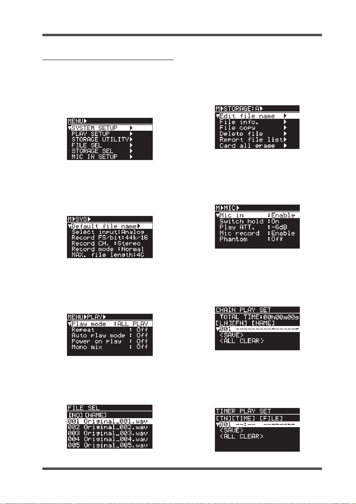
Home screen in record or input monitor mode
1
7
6
5
1) Time information
During recording or in input monitor mode, the
current recorder position is shown.
Pressing the [TIME] key switches between the
time display and the remaining time display of
the storage device.
Also the record icon ( ) is lit in the top right of
the display during recording.
2) Margin
The margin of the input signal level is displayed
during recording or in input monitor mode.
The margin display can be reset by pressing the
[MRGN RST] key in shift mode.
3) Level meters
The input (recording) levels are displayed
during recording or in the input monitor mode
(see page 33).
4) Input source
The currently selected input source ( ,
or ) is displayed. You can select (Digital) or (Analog) using the "Select input"
item in the SYSTEM SETUP menu of the MENU
mode (Note that even if you select Digital, when
the unit does not lock to the digital input
signal, flashes quickly).
When turning on the [MIC IN] indicator by
pressing the [MIC IN] key, is selected (see
page 34).
3
4
7) File number/file name
In the input monitor mode, "NEXT" is displayed
in the file number field, while the file name of
the next recording is displayed in the file name
field.
During recording, the current file number and
file name are displayed.
As with the file number shown on the Home
screen in stop or playback mode, the first
alphabetical character in a file number shows
2
the storage device where the current file is
recorded (such as A001, B001 and C001).
The file name format depends on the selection
of the "Default file name" item in the SYSTEM
SETUP menu of the MENU mode (see page 73).
• When Date is selected:
The internal realtime clock data when
recording starts (with ".wav", the file extension)
is set to the file name.
Example: B15h09m27s10aug2008.wav
• When Take is selected (default):
"Scene name + Take Number" (with ".wav", the
file extension) is set to the file name.
Example: SCENE_001.wav
• When Reel is selected:
"Reel number + File number" (with ".wav", the
file extension) is set to the file name.
Example: 12082008_001.wav
5) Sampling frequency/quantization bit
The Fs and bit information of the current file is
displayed. You can select the desired Fs and bit
using the "Record FS/bit" item in the SYSTEM
SETUP menu of the MENU mode (see page 74).
6) File format
The file format of the current file (BWF) is
displayed.
-18-
Model UR-2 <Names and functions>
Screens in MENU mode
When the unit enters the MENU mode by pressing the [ENTER] key while the unit is stopped,
the menu list screen as below is shown.
There are ten main menus. To bring up a main
menu screen, use the [MENU] dial to highlight a
desired main menu from the menu list and press
the [ENTER] key.
• SYSTEM SETUP menu
By highlighting "SYSTEM SETUP" in the menu
list and pressing the [ENTER] key, the following screen is shown. In the SYSTEM SETUP
menu, you can make system settings (see page
71).
• STORAGE UTILITY menu
By highlighting "STORAGE UTILITY" in the
menu list and pressing the [ENTER] key, the
following screen is shown. In the STORAGE
UTILITY menu, there are menu items regarding storage devices and recorded files (see
page 82).
• MIC IN SETUP menu
By highlighting "MIC IN SETUP" in the menu
list and pressing the [ENTER] key, the following screen is shown. In the MIC IN SETUP menu,
you can make settings for using an external
microphone (see page 39).
• PLAY SETUP menu
By highlighting "PLAY SETUP" in the menu list
and pressing the [ENTER] key, the following
screen is shown. In the PLAY SETUP menu, you
can make settings regarding playback
functions (see page 56).
• FILE SEL menu
By highlighting "FILE SEL" in the menu list and
pressing the [ENTER] key, the following screen
is shown. In the FILE SEL menu, you can select
a file to be played back (see page 42).
• CHAIN PLAY SET menu
By highlighting "CHAIN PLAY SET" in the menu
list and pressing the [ENTER] key, the following screen is shown. In the CHAIN PLAY SET
menu, you can make playlist which is used in
chain play (see page 46).
• TIMER PLAY SET menu
By highlighting "TIMER PLAY SET" in the menu
list and pressing the [ENTER] key, the following screen is shown. In the TIMER PLAY SET
menu, you can set the start time and end time
which are used in timer play (see page 51).
-19-
Model UR-2 <Names and functions>
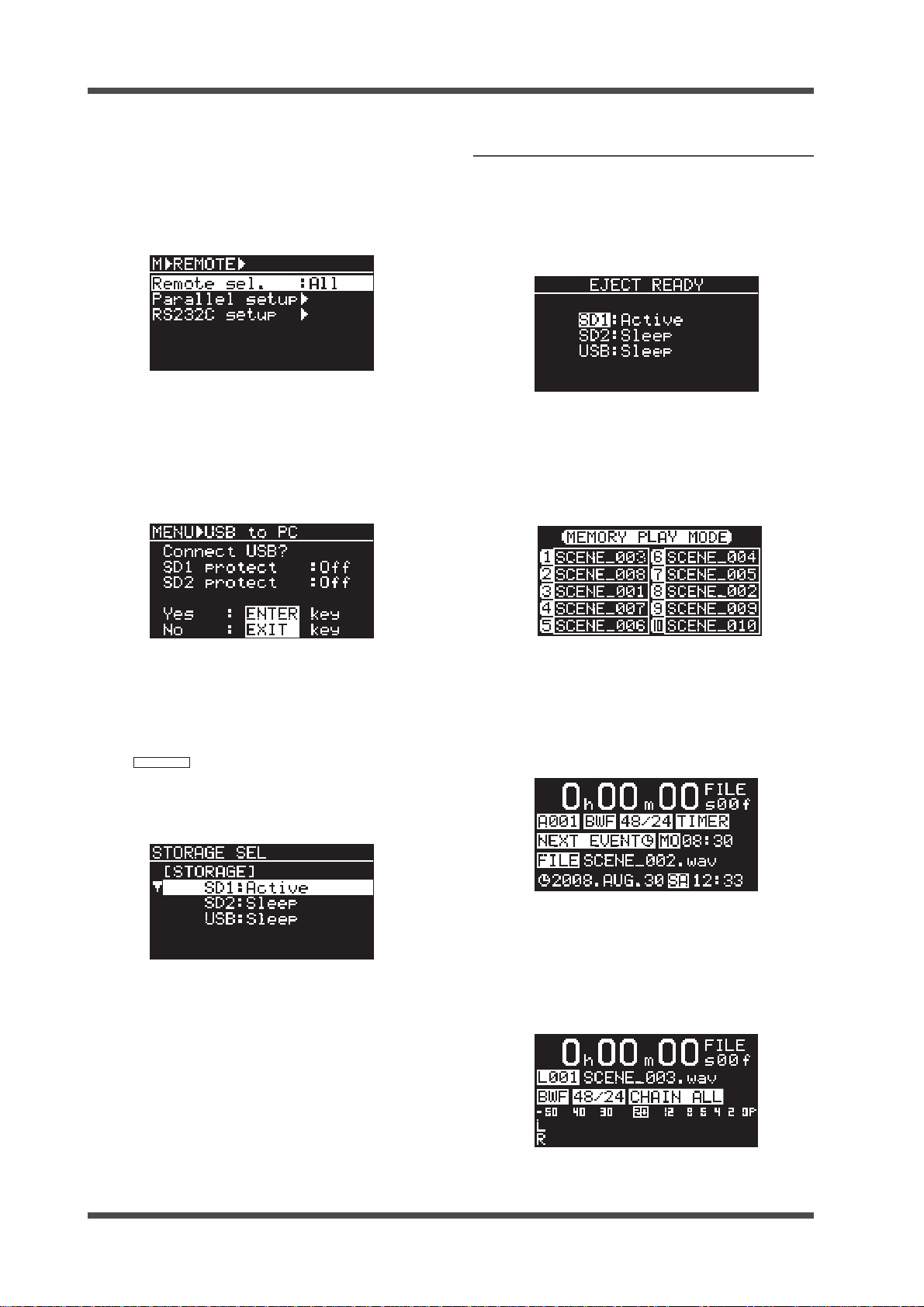
• REMO TE SET menu
By highlighting "REMOTE SET" in the menu
list and pressing the [ENTER] key, the following screen is shown. In the REMOTE SET menu,
you can make settings for controlling the unit
remotely (see page 61).
• USB to PC menu
By highlighting "USB to PC" in the menu list
and pressing the [ENTER] key, the following
screen is shown. In the "USB to PC" menu, you
can make settings for transferring files
between the unit and a computer (see page
65).
Other screens
• EJECT READY screen
Pressing the [EJECT READY] key while the unit
is stopped brings up the following screen.
Use this screen when you eject the current
storage device (see page 27).
• Memory play screen
When you set the play mode to "MEMORY",
the memory play screen is shown (see page
45). The memory play screen is shown only
when the playlist for memory play is created
(see page 46).
• STORAGE SEL menu
By highlighting "STORAGE SEL" in the menu
list and pressing the [ENTER] key, the following screen is shown. Alternatively you can
bring up this screen by pressing the [FILE SEL]
STRG SEL
/ [[
In the STORAGE SEL menu, you can select the
current storage device for recording/playback
(see page 28).
] key in SHIFT mode.
• Timer play screen
When you execute timer play, the timer play
screen is shown (see page 45).
The timer play screen is shown only when
the playlist for timer play is created (see page
51).
• Chain play screen
When you execute chain play, the “CHAIN-S”
or “CHAIN-A” screen is shown (see page 44).
The chain play screen is shown only when
the playlist for chain play is created (see page
46).
-20-
Preparation
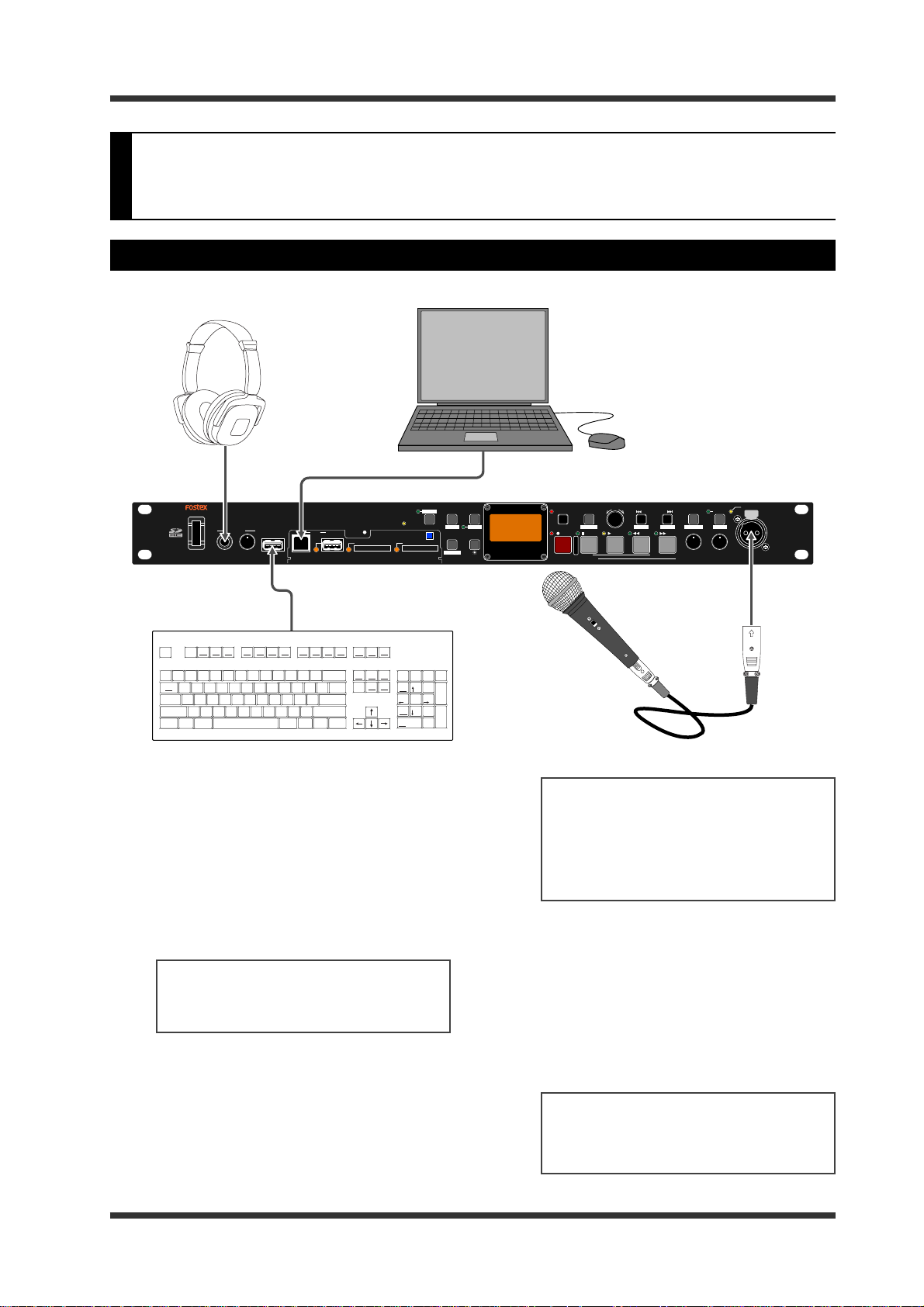
Connection to external devices (fr om the fr ont panel)
Model UR-2 <Preparation>
[PHONES] jack
POWER
PHONES
USB
(KYBD ONLY)
MIN
MAX
[USB (PC)] port
USBPC
HOST
[USB (KYBD ONLY)] port
F1
ESC
~
`
TAB
Caps Lock
SHIFT
Ctrl
!
1
F2
F3
Help
$
@2#
4
3
EWQ
ASDF
ZXCV
Alt
F5
F4
%5^
&
6
7
GHJ K
BNM
F8F7F6
(
)
*
8
9
0
UYTR
LJK
<
>
,
Alt
F12F11
F10F9
_
Back Space
-+=
{
}
|
POI
[
]
/
ENTER
?
SHIFT
.
/
Ctrl
Connection of headphones
Connect headphones to the [PHONES] jack.
Use the [PHONES] control to adjust the
headphone level.
Connection to a computer
Connect a computer to the [USB-PC] (USB
2.0) port. You can transfer a file between
the unit and computer at high speed (see
page 65).
<Note>:
When a USB memory is connected to the [USB HOST] port, you cannot use the [USB-PC] (USB2.0) port.
Connection of a USB keyboard
Connect a USB keyboard (or a numeric
keyboard) to the [USB (KYBD ONLY)] port.
You can edit a file name and control the
transport from a USB keyboard (see page
67).
PLAY
SHIFT
MODE
AUTO PLAY
EJECT
READY
SD-1
SD-2
TIME
EDIT
REPEAT
FILE SEL DISPLAY
STRG SEL
STEREO RACK MEMORY RECORDER
REC RDY
UR-2
MENU / ENTER
EXIT
MRGN RST
REC
STOP
ABS 0
REC END
FILE/CURSOR
CUE/LOCATE
CUEPREV NEXT
TIME EDIT
PLAY
F FWD
REW
MIN
PHANTOM
MIC IN
MIC SET
MIN
MAX
MAX
MIC GAIN MIC ININPUT LEVEL
[MIC IN] connector
Print
Scroll
Pause
Screen
Lock
Break
SysReq
Page
Num
Insert
Home
Up
Page
End
Delete
Down
Lock
89
7
Home
45
2
1
End
0
Ins
-
/
*
Pg Up
+
6
3
Pg Dn
Enter
.
Del
<Note>:
When you use a USB keyboard,
set the keyboard type (US or JAPAN)
appropriately using the “Keyboard
Type” menu item in the “SYSTEM SETUP”
menu of the MENU mode (see page 78
for details).
Connection of an external microphone
Connect an external microphone to the
[MIC IN] connector.
To enable the microphone input, press the
[MIC IN] key to turn on the [MIC IN] indicator.
The [MIC IN] connector supports +48 V
phantom power, therefore, you can use a
condenser microphone.
<Note>:
external microphone with the unit, see
"Using an external microphone" (page
38).
For details about how to use an
-21-
Model UR-2 <Preparation>
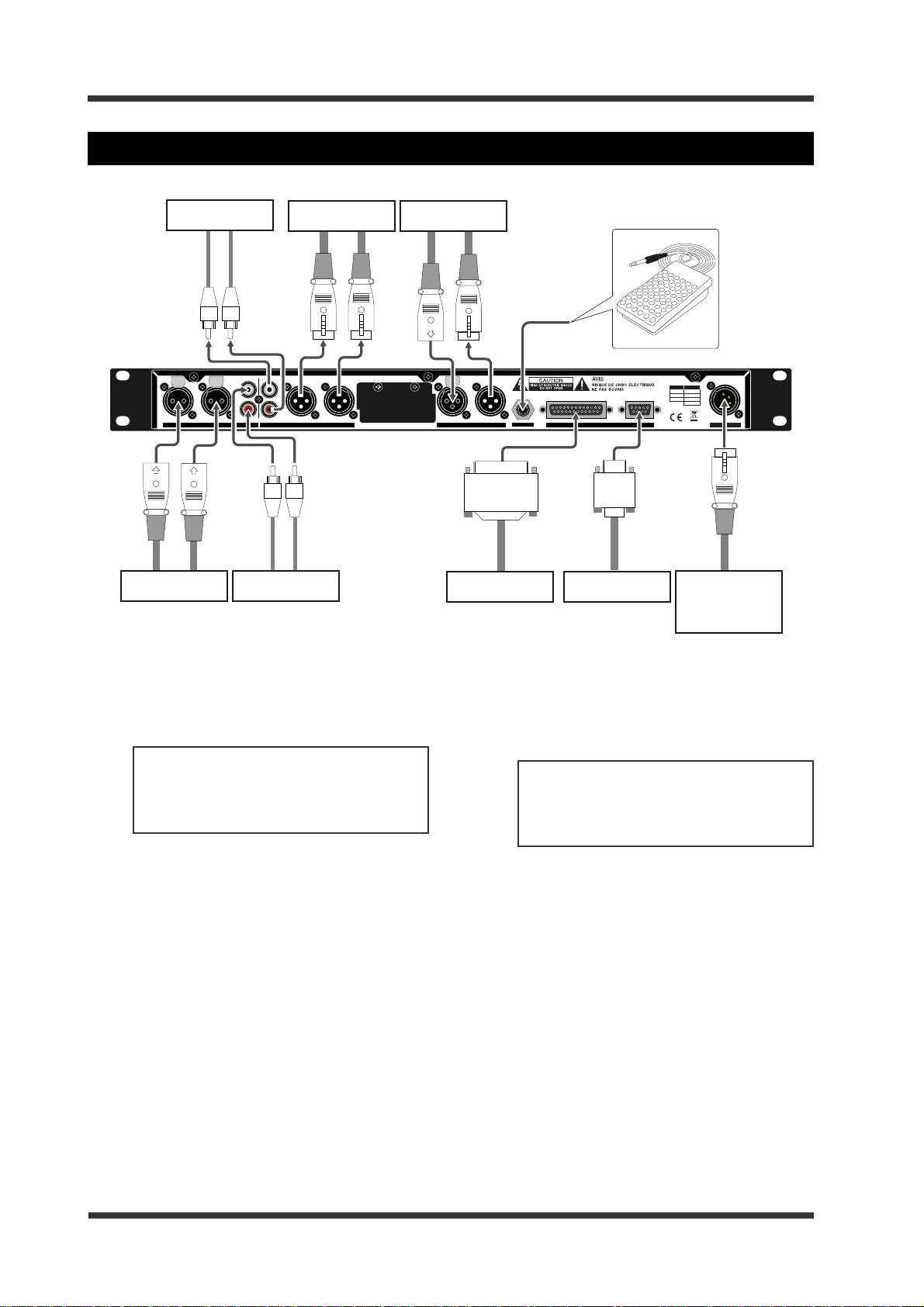
Connection to external devices (fr om the rear panel)
Analog device
LLR
R
UNBALANCED [-10dBV]
ANALOG INPUT
Analog device Digital device
R
L
R
BALANCED [+4dBu]BALANCED [+4dBu]
ANALOG OUTPUT
Analog device Analog device
Analog audio connection
For analog audio input/output connection,
the UR-2 provides both the +4 dBu
balanced XLR and -10 dBV unbalanced RCA
input/output connectors.
<Note>:
inputs simultaneously. If you connect
devices to both inputs, the RCA input is
enabled.
You cannot use the XLR and RCA
L
MIDI
INPUTINPUT
OUTPUTOUTPUT
DIGITAL
External controller
FOOT SW
REMOTE
Computer
XLR DC-IN
1:GND
1:GND
2:HOT
3:COLD
2:NC
3:NC
4:12-24V
12-24V
DC-IN
RS-232CPARALLEL
AC adaptor
or
external battery
Power connection
Connects the supplied AC adaptor or an
appropriate external battery with the DC
power from 12V to 24V to the [DC IN]
connector.
The connector is the XLR-4-32 type.
<Note>:
from an external battery, make sure that
the battery can supply stable rated voltage.
When you supply the power
Digital audio connection
For digital audio input/output connection,
the UR-2 provides the balanced XLR
connectors which support IEC-60958 (AES/
EBU) and IEC-60958 (S/P DIF).
The unit automatically recognizes the
digital signal format, while the digital
output signal format can be selected via
the "Digital out" menu item in the SYSTEM
SETUP menu of the MENU mode (see page
77).
Footswitch or equipment with fader start terminal
By connecting a footswitch or fader start
terminal to the [FOOT SW] jack, you can
start or stop playback (page 61).
RS232C connection
By connecting the [REMOTE RS232C]
connector to the RS-232C port of a
computer, you can control the unit from
the computer (see page 61).
Parallel remote connection
By using the [REMOTE PARALLEL]
connector, you can control the unit from
an external controller.
The [REMOTE PARALLEL] connector is the
D-sub 25 pin type. For details about the
pin assignment of the [REMOTE PARALLEL]
connector, see "Parallel remote control" on
page 61.
-22-
Model UR-2 <Preparation>
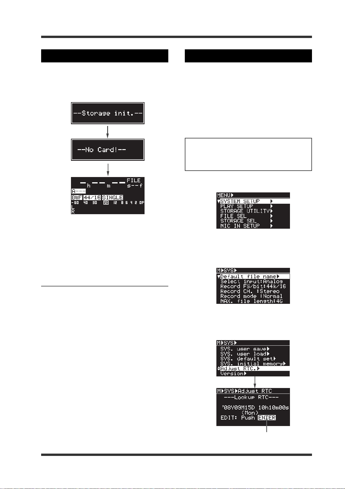
Turning on the power
By pressing the [POWER] switch, you can power
on the unit.
If the unit starts up without any storage devices
inserted, the display shows the following Home
screen.
Setting the internal clock
The UR-2 has the internal clock, which is adjusted
according to the local time when shipped. Therefore, set the time to your local time before using
the unit.
The internal clock time is used for the default
file name of a file which is created when recording, the file creation date/time, the time stamp
of a BWF file, and the start time of the timer play
function. Therefore, it is recommended to set the
internal clock correctly.
<Note>:
the "Default File name" item in the SYSTEM
SETUP menu of the MENU mode appropriately
(see page 73).
1) Press the [ENTER] key to enter the MENU mode.
To add the time data to a file name, set
For details about the display shown when starting up the unit with a storage device inserted,
see "Setting a storage device" on page 26.
Turning off the power
To turn off the power, simply press the [POWER]
switch.
However, during playback or recording, the
[POWER] switch is disabled and you cannot turn
off the power by pressing the [POWER] switch.
2) While "SYSTEM SETUP" is highlighted, press
the [ENTER] key.
The display now shows the menu items of
the SYSTEM SETUP menu.
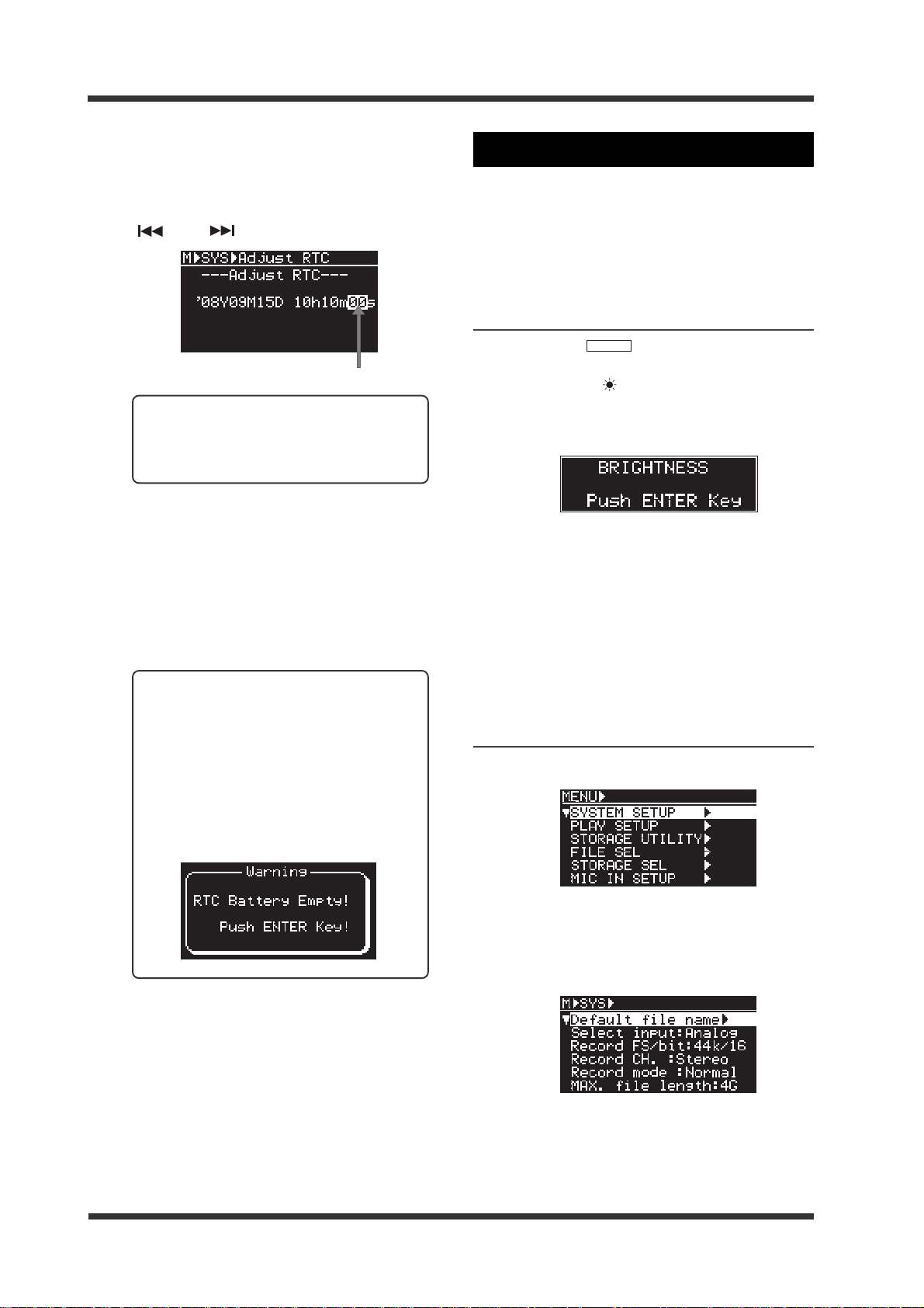
3) Use the [MENU] dial to highlight "Adjust RTC."
and press the [ENTER] key.
The display now shows the current date/
time of the internal clock.
-23-
Flashing
Model UR-2 <Preparation>
4) Press the [ENTER] key.
The second digit starts flashing.
You can edit the value at the flashing point
using the [MENU] dial.
You can move the flashing point using the
[ ] and [ ] keys.
Flashing
<Memo>: When a USB keyboard is connected to the unit, you can also enter
time data from the keyboard (see page
67).
5) After editing time data, press the [ENTER] key
to confirm the editing.
By pressing the [ENTER] key at the timing
of time signal, you can set the exact time.
6) Press the [STOP] key to e xit the MENU mode.
You can also exit the MENU mode by
pressing the [EXIT] key repeatedly.
Adjusting the display
You can adjust the brightness of the display, inverse the display and enlarge the file name display.
In the following description, it is assumed that
the unit is stopped.
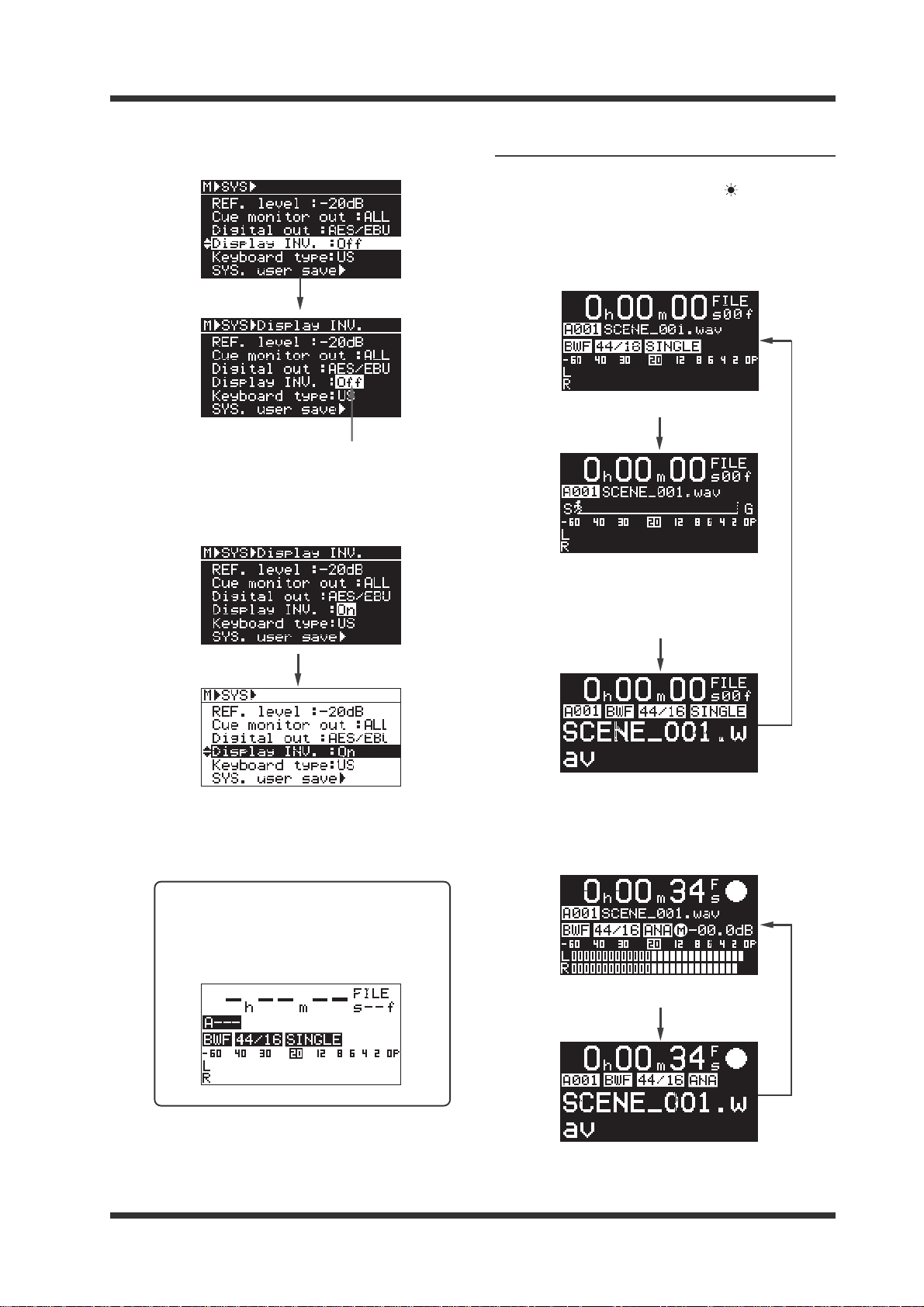
Adjusting the brightness of the display
1) Press the [
(light up the SHIFT indicator) and press the
[DISPLAY] / [
The following popup window appears on
the display.
2) Use the [MENU] dial to adjust the brightness
and press the [ENTER] key to confirm the
setting.
The default brightness value is the
maximum brightness.
Pressing the [ENTER] key dismisses the
popup window.
SHIFT
] key to enter the shift mode
] key.
<Memo>: The unit has an internal
lithium battery which is used for driving the realtime clock. The battery life
is approximately four or five years.
Battery replacement must be performed
by an authorized person only.
If the following message appears on the
display, ask your local Fostex dealer or
sale office for battery replacement.
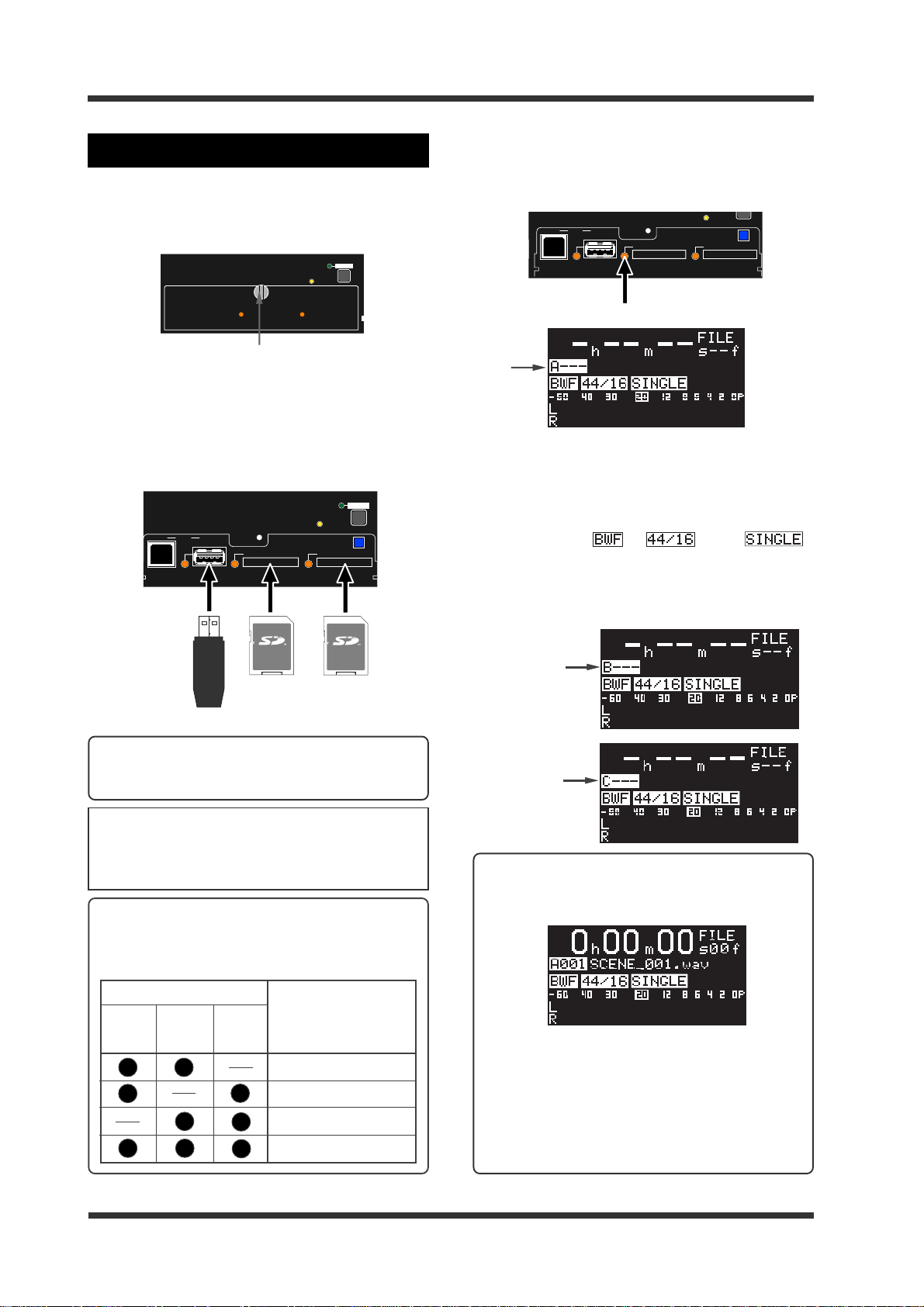
Inversing the displa y
1) Press the [ENTER] key to enter the MENU mode.
2) While "SYSTEM SETUP" is highlighted, press
the [ENTER] key.
The display now shows the menu items of
the SYSTEM SETUP menu.
3) Use the [MENU] dial to highlight "Display INV."
and press the [ENTER] key.
-24-
Model UR-2 <Preparation>
The current setting (Off by default) flashes.
You can select Off or On.
Flashing
4) Use the [MENU] dial to select "On" and press
the [ENTER] key.
The display is inversed.
Enlarging the file name display
In Non-shift mode (when the SHIFT indicator is
unlit), pressing the [DISPLAY] / [ ] key switches
the display as follows.
<While the unit is stopped>
<Normal display>
<Playback position display>
While playback proceeds, the
runner moves from S (start)
towards G (goal).
5) Press the [STOP] key to exit the MENU mode.
You can also exit the MENU mode by
pressing the [EXIT] key repeatedly.
<Memo>: When you set "Display INV."
to "On", the display looks like the following (the following shows the Home
screen when no storage device is inserted).
<Enlarged file name>
<During recording>
<Normal display>
<Enlarged file name>
-25-
Model UR-2 <Preparation>
F
S
)
Inserting a storage device
To insert a storage device, loosen the fixing screw
and open the protection cover for the slots (you
can remove the cover by opening it approximately 45 degrees and pulling it up).
SHIFT
AUTO PLAY
USBPC
HOST
SD-1
SD-1 SD-2
Fixing screw
You can insert up to three storage devices into the
slots/ports: two SD (SDHS) cards to the [SD-1] and
[SD-2] slots and a USB memory to the [USB HOST]
port. If you insert more than one storage device
after turning on the power, the first device you insert is selected as the current storage device.
USBPC
HOST
SD-1
LOCK
EJECT
READY
SD-2
AUTO PLAY
SD-2
LOCK
EJECT
READY
SHIFT
For example, when an unrecorded SD card is inserted, the unit turns on the [SD-1] indicator in green
and brings up the following screen after reading
the card information.
USBPC
HOST
SD-1
SD-2
EJECT
READY
Lit
"A" is added to the beginning of a file number. This
means the SD card on the [SD-1] slot is now selected
as the current storage device.
You can also see the file format, FD/bit and play
mode under the file number. On the screen example
below, they are "
", " " and " ".
When the SD card on the [SD-2] slot or USB memory
is selected as the current storage, the appropriate
alphabetical character is added to the beginning of
a file number, as shown below.
SD (SDHC) card
USB memory
<Memo>: The protection cover can be closed even
when both the [SD-1] and [SD-2] slots are occupied.
<Note>:
See "Changing the current storage device"
described on page 28 for details about how to
change the current storage device when more
than one device is inserted.
<Memo>: When you turn on the power with more
than one storage device inserted, the following
device is selected as the current storage device
preferentially.
Storage device inserted
The storage device
selected as the current
SD-1SD-1
SD-1
SD-1SD-1
SD-2SD-2
SD-2
SD-2SD-2
USBUSB
USB
USBUSB
storage device
preferentially
SD card on the [SD-1] slot
SD card on the [SD-1] slot
SD card on the [SD-2] slot
SD card on the [SD-1] slot
The current
storage device is
SD-2
The current
storage device is
USB
<Memo>: When the unit is turned on while the
current storage device has one or more recorded
files, it stops at the beginning of the first recorded
file.
You can automatically start playback after turning on the power when a recorded storage device is inserted to the slot/port (see page 58).
When the unit is turned on while the current storage device has any folder other than the BWFF
folder, the display shows the screen for selecting
a folder (see pages 28 and 29).
-26-
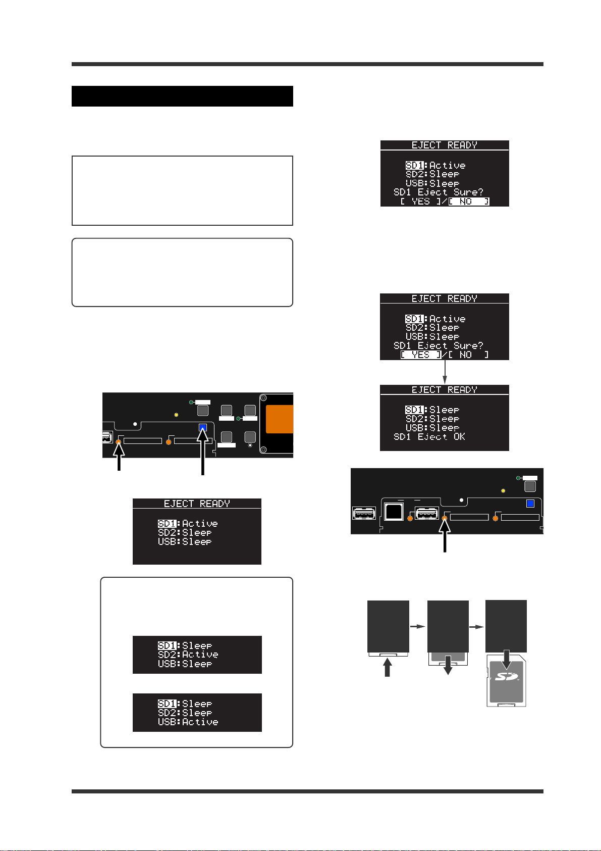
Model UR-2 <Preparation>
R
M
Removing a storage device
The following shows the procedure of removing
a storage device on the [SD-1] slot when the power
is on. It is assumed that the unit is stopped.
<Note>:
the power is on, turn off the associated slot
indicator in the following manner. If you remove a storage device when the associated slot
indicator is lit, recorded data may be damaged.
<Memo>: If you remove a storage device when
the power is off, no special operation is required.
For an SD care, push it down and then pull it
out. For a USB memory, simply pull out the
memory.
1) Press the [EJECT READ Y] ke y.
If you remove a storage device when
The display shows the screen below.
You can see SD1 is active (i.e. selected as
the current storage device).
2) While "SD1" is highlighted, press the [ENTER]
key .
"NO" at the bottom of the screen is now
highlighted.
3) Use the [MENU] dial to highlight "[YES]" and
press the [ENTER] key.
The screen shows that the SD1 condition
changes to "Sleep", while the SD1
indicator on the front panel turns off.
You can now eject the SD card.
PLAY
SHIFT
MODE
AUTO PLAY
T
SD-1
Lit
EJECT
READY
SD-2
[EJECT READ Y] key
TIME
EDIT
REPEAT
FILE SEL DISPLAY
STRG SEL
STEREO RACK ME
<Memo>: When SD-2 or USB memory is
active, the screen shows as follows.
The current storage device is SD-2
The current storage device is USB
U
SD-2
EJECT
READY
SHIFT
USB
(KYBD ONLY)
AUTO PLAY
USBPC
HOST
SD-1
Light off
4) Push down the SD card set in the [SD-1] slot
and then pull it out.
LOCK
LOCK
LOCK
5) Press the [EXIT] key (or [STOP] key) to exit eject
mode.
-27-
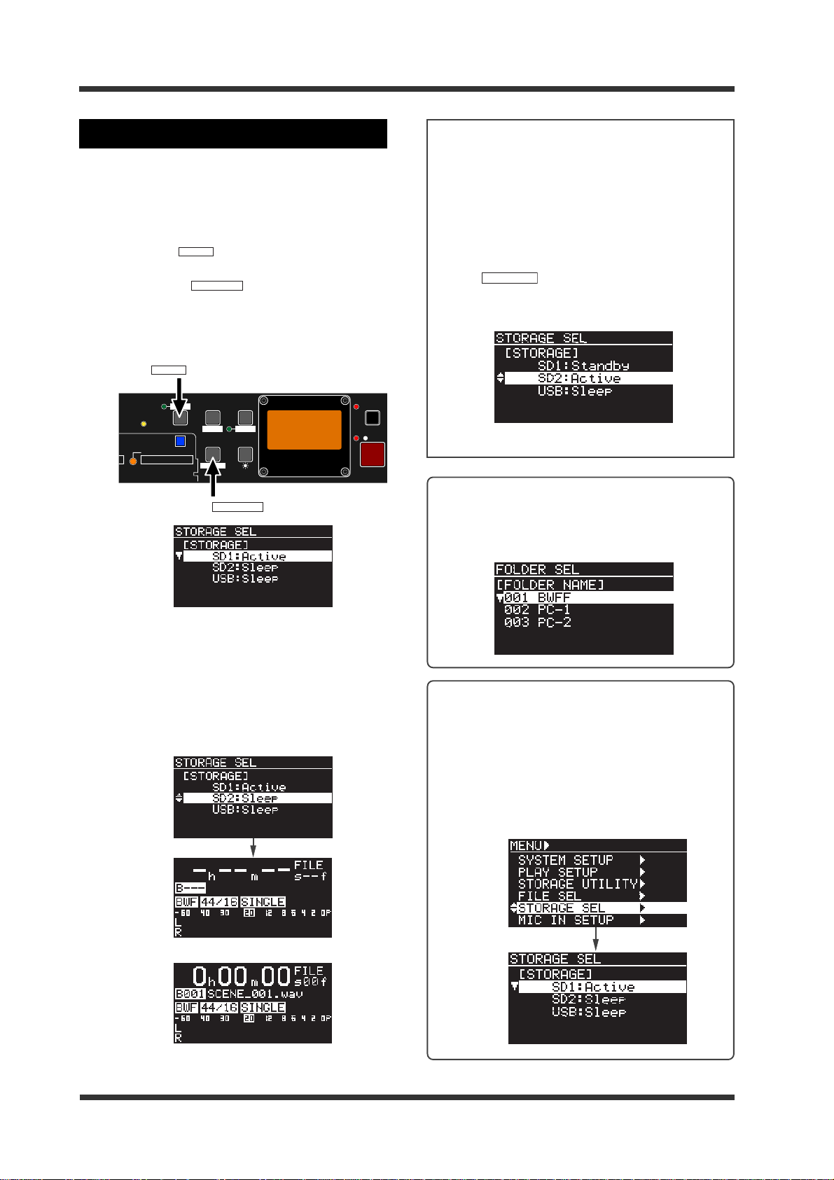
Model UR-2 <Preparation>
STRG SEL
Selecting a storage device
When more than one storage device is set, you
can select the desired device as the current storage. The following shows the procedure example
in which the current storage device is changed
from SD-1 to SD-2.
1) Press the [
(light up the SHIFT indicator) and press the
[FILE SEL] / [
The display now shows the storage device
selection screen. For the current storage device,
"Active" is shown. For another storage device,
"Sleep" is shown.
AUTO PLAY
SHIFT
STRG SEL
SHIFT
[
] key
SHIFT
EJECT
READY
SD-2
[FILE SEL] / [
] key to enter the shift mode
] key .
PLAY
MODE
TIME
EDIT
REPEAT
FILE SEL DISPLAY
UR-2
STRG SEL
STRG SEL
STEREO RACK MEMORY RECORDER
] key
REC RDY
REC
<Note>:
When you switch the current storage
device from SD1 to SD2, both SD1 and SD2 indicators light in green.
This means both cards are mounted to the unit
and get power from the unit even though the
current storage device is switched.
You can check the current storage device by the
first character of the file number.
If you press the [SHIFT] key followed by the [FILE
SEL] / [
] key (or if you press the [EJECT
READY] key) in this condition, SD2 becomes
"Active" while SD1 becomes "Standby".
Example of the storage selection screen
<Memo>: When the unit is turned on while the
current storage device has any folder other than
the BWFF folder, the display shows the screen
for selecting a folder, as shown below (see next
page).
2) Use the [MENU] dial to select SD2 and press the
[ENTER] key .
The current storage is now changed to SD2.
Depending on whether the SD card in the
[SD-2] slot is new or recorded, the screen looks
differently (see below). In both cases, the file
number starts with "B", showing that the
current storage device is SD2.
<When a new SD card is set>
<Memo>: You can also select the current stor-
age device by the following procedure.
1) While the unit is stopped, press the
[ENTER] key to enter the MENU mode.
2) Use the [MENU] dial to select "STORAGE
SEL" and press the [ENTER] key.
The display shows the storage selection
screen.
<When a recorded SD card is set>
-28-
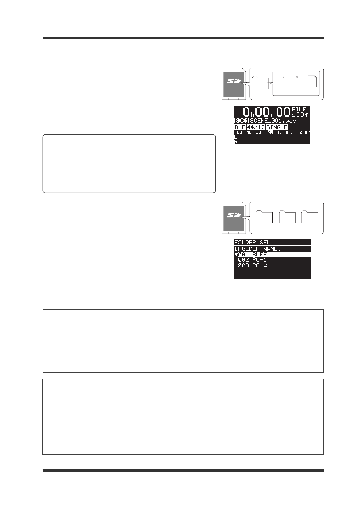
Model UR-2 <Preparation>
<Basic knowledge about folder s and files on a storage device>
The first time you make recording to a new storage device, the
"BWFF" folder is automatically created on the root (the top level
folder), and a BWF file is created in the "BWFF" folder. The unit
does not create more than one "BWFF" folder on a storage device.
As far as you repeat recording using the unit, a created BWF file is
stored in the one and only "BWFF" folder.
When you turn on the unit whose current storage device has only
the "BWFF" folder, it locates the beginning of the first recorded file
(see page 28).
<Memo>: If you copy a folder (with BWF files) named "BWFF"
from a computer to a new storage device and use it as the current storage device of the unit, then the unit locates the beginning of the first created file, as same as above. If you want to
copy the BWF files stored in the "BWFF" folder from a computer
to the storage device in which the "BWFF" folder already exists,
copy only the files to the existing “BWFF” folder in the storage
device or rename the “BWFF” folder.
You can create a folder (other than the "BWFF" folder) using a computer. The right shows the example of a storage device which has
the "BWFF" folder created by the unit and two folders created by a
computer.
When the current storage device has more than one folder as the
example in the upper right, the unit shows the folder selection screen
as in the lower right.
If the folder selection screen is shown, use the [MENU] dial to select
a desired folder and press the [ENTER] key. You can record an audio file to the selected folder, as well as play back an audio file on
the selected folder. To select another folder, press the [SHIFT] key
to enter the shift mode and press the [FILE SEL] key, then use the
[MENU] dial to select the active storage device and press the [ENTER] key. The folder selection screen appears and you can select
the desired folder.
LOCK
LOCK
BWFF
BWFF
SCENE_002.wav
SCENE_001.wav
PC-1 PC-2
SCENE_nnn.wav
<Notes on copying a file from a computer>
When you copy a file from a computer, note the following (see "Copying a file from a computer" on page 65).
(1) When you only copy a file, cop y destination must be the "BWFF" f older (or a folder created using a computer).
If you copy a file directly to the root directory, the unit cannot recognize it.
(2) Name the folder using one-byte alphan umeric character s.
(3) You can create folders only in the r oot directory.
The subfolder cannot be recognized.
<Notes on using a storage device which has more than one folder>
When the current storage device has more than one folder, do not use the following UR-2 functions. These
functions are available with a storage device which has only the "BWFF" folder.
(1) Power on play function (which automatically starts playback after the unit is turned on. See page 58.)
When the unit is turned on, the folder selection screen is shown. The unit does not start playback
automatically.
(2) Relay play mode (which allows playback of all files on all the storage devices continuously. See page 43).
When the unit switches the current storage device to the one which has more than one folder, the folder
selection screen is shown and playback stops.
-29-
 Loading...