

Page 1
Owner’s Manual
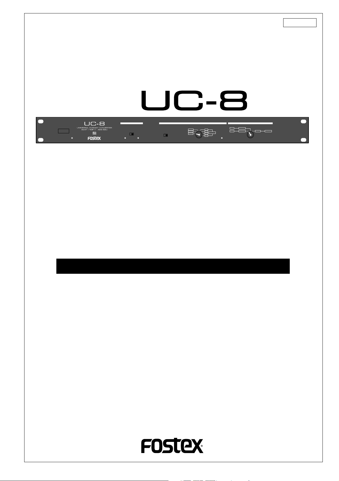
Universal Format Converter
Model
8288 485 000
POWER
FS SELECT
ADAT
75Ω
48kHz44.1kHz
TERMINATION
ON OFF
TDIF-1
WORD
1-2
3-4
AES/EBU
5-6
LOCKED
7-8
FORMAT CONVERSIONCLOCK SELECT
ADAT
TDIF-1
AES/EBUADAT
TDIF-1
AES/EBU
Introduction
The Model UC-8 is a universal format converter that converts the format of the digital input
signal to different format. It can convert between adat digital and AES/EBU, adat digital and
TDIF-1, and AES/EBU and TDIF-1.
By inserting the UC-8 between two digital recorders which have different digital formats, you
can digitally transfer signals between them (44.1 kHz/48 kHz, 24-bit digital signals only).
Please read this manual thoroughly before using the converter.
Table of Contents
Safety Instructions.......................................................................................................2
Names and Functions..................................................................................................3
Basic Connections and Settings................................................................................4
Between adat and TDIF-1 devices...............................................................................4
Between adat and AES/EBU devices...........................................................................5
Between AES/EBU and TDIF-1 devices.......................................................................6
Specifications...............................................................................................................7
Page 2
CAUTION
RISK OF ELECTRIC SHOCK
DO NOT OPEN
CAUTION: TO REDUCE THE RISK OF ELECTRIC SHOCK,
DO NOT REMOVE COVER (OR BACK).
NO USER - SERVICEABLE PARTS INSIDE.
REFER SERVICING TO QUALIFIED SERVICE PERSONNEL.
"WARNING"
"TO REDUCE THE RISK OF FIRE OR ELECTRIC SHOCK,
DO NOT EXPOSE THIS APPLIANCE TO RAIN OR
MOISTURE."
CAUTION:
TO PREVENT ELECTRIC SHOCK, MATCH WIDE BLADE OF
PLUG TO WIDE SLOT, FULLY INSERT.
ATTENTION:
POUR EVITER LES CHOCS ELECTRIQUES, INTRODUIRE
LA LAME LA PLUS LARGE DE LA FICHE DANS LA BORNE
CORRESPONDANTE DE LA PRISE ET POUSSER JUSQU'
AU FOND.
The lightning flash with arrowhead symbol, within an equilateral
triangle, is intended to alert the user to the presence of
uninsulated "dangerous voltage" within the product's enclosure
that may be of sufficient magnitude to constitute a risk of electric
shock to persons.
The exclamation point within an equilateral triangle is intended
to alert the user to the presence of important operating and
maintenance (servicing) instructions in the literature
accompanying the appliance.
SAFETY INSTRUCTIONS
1. Read Instructions - All the safety and operating instructions
should be read before the appliance is operated.
2. Retain Instructions - The safety and operating instructions
should be retained for future reference.
3. Heed Warnings - All warnings on the appliance and in the
operating instructions should be adhered to.
4. Follow Instructions - All operating and use instructions should
be followed.
5. Water and Moisture - The appliance should not be used near
water - for example, near a bathtub, washbowl, kitchen sink,
laundry tub, in a wet basement, or near a swimming pool, and
the like.
6. Carts and Stands - The appliance should be used only with a
cart or stand that is recommended by the manufacturer.
An appliance and cart combination should be moved with care.
Quick stops, excessive force, and uneven surfaces may cause
the appliance and cart combination to overturn.
7. Wall or Ceiling Mounting - The appliance should be mounted to
a wall or ceiling only as recommended by the manufacturer.
8. Ventilation - The appliance should be situated so that its location
or position dose not interfere with its proper ventilation.
For example, the appliance should not be situated on a bed,
sofa, rug, or similar surface that may block the ventilation
openings; or, placed in a built-in installation, such as a bookcase
or cabinet that may impede the flow of air through the ventilation
openings.
9. Heat - The appliance should be situated away from heat sources
such as radiators, heat registers, stoves, or other appliances
(including amplifiers) that produce heat.
10. Power Sources - The appliance should be connected to a power
supply only of the type described in the operating instructions or
as marked on the appliance.
11. Grounding or Polarization - The precautions that should be taken
so that the grounding or polarization means of an appliance is
not defeated.
12. Power Cord Protection - Power supply cords should be routed
so that they are not likely to be walked on or pinched by items
placed upon or against them, paying particular attention to cords
at plugs, convenience receptacles, and the point where they
exit from the appliance.
13. Cleaning - The appliance should be cleaned only as
recommended by the manufacturer.
14. Nonuse Periods - The power cord of the appliance should be
unplugged from the outlet when left unused for a long period of
time.
15. Object and Liquid Entry - Care should be taken so that objects
do not fall and liquids are not spilled into the enclosure through
openings.
16. Damage Requiring Service - The appliance should be serviced
by qualified service personnel when:
A. The power supply cord or the plug has been damaged; or
B. Objects have fallen, or liquid has been spilled into the appliance; or
C. The appliance has been exposed to rain; or
D. The appliance does not appear to operate normally or
exhibits a marked change in performance; or
E. The appliance has been dropped, or the enclosure damaged.
17. Servicing - The user should not attempt to service the appliance
beyond that described in the operating instructions.
All other servicing should be referred to qualified service
personnel.
2
Page 3
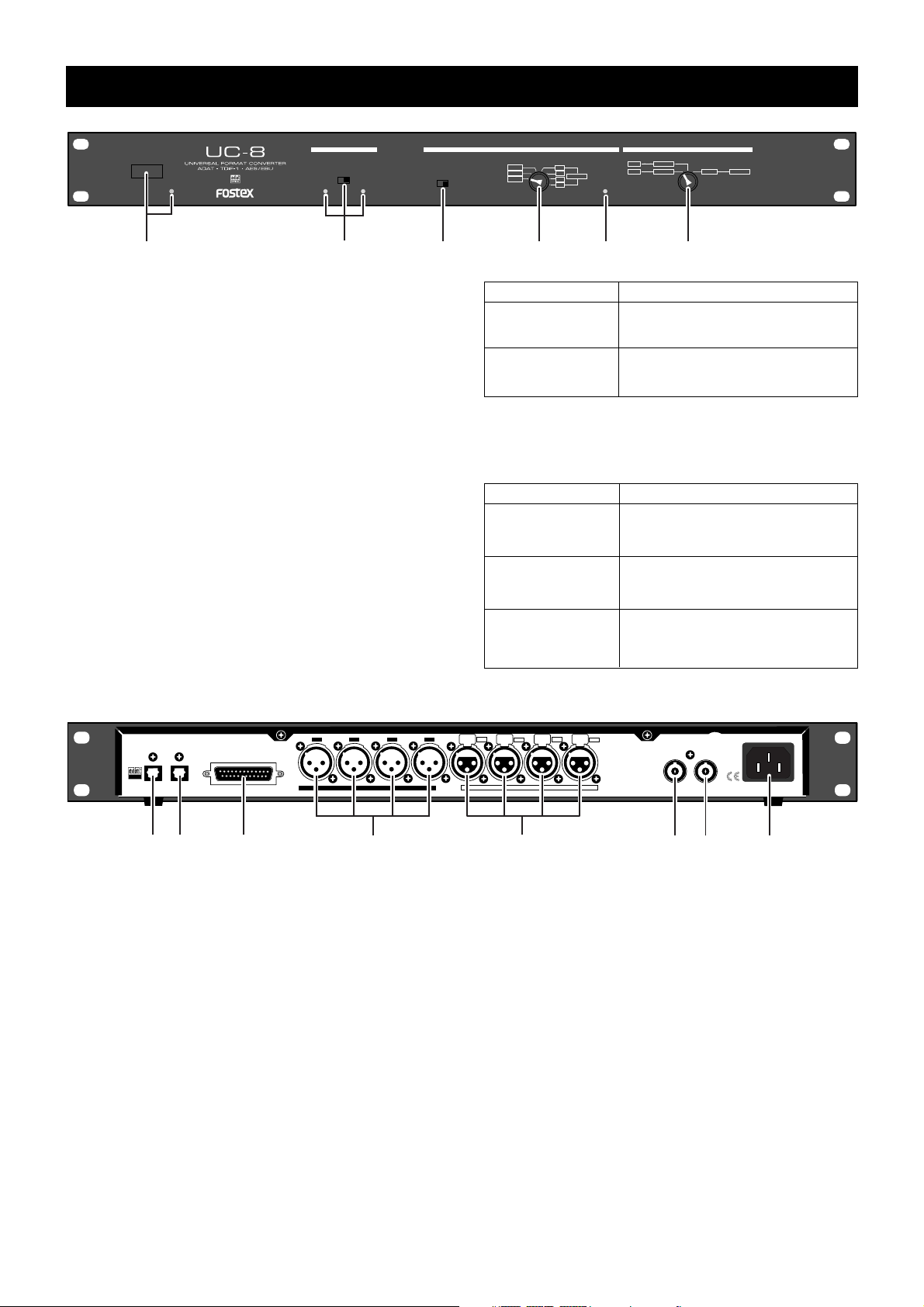
Names and Functions
FS SELECT
POWER
1
48kHz44.1kHz
2
1. POWER switch and indicator
Turns on or off the power to the UC-8.
When on, the indicator illuminates on green.
2. Fs SELECT switch and indicator s
Selects the Fs when converting an adat digital signal
that does not have the Fs status information in the
signal. You can select 44.1 kHz or 48 kHz, and the
appropriate indicator illuminates.
When converting signals which contains the Fs status
information in the signals, it takes priority and the
setting of the Fs SELECT switch is ineffective.
3. 75Ω TERMINA TION switch
Set the switch to ON when receiving an external word
clock. Otherwise, set the switch to OFF.
4. CLOCK SELECT switch
Selects the master clock.
See "Basic Connections and Settings" for details.
5. LOCKED indicator
Shows the status of the clock selected by the CLOCK
SELECT switch as follows.
75Ω
TERMINATION
ON OFF
ADAT
TDIF-1
WORD
34
1-2
3-4
AES/EBU
5-6
LOCKED
7-8
5
CLOCK Select
ADAT or AES/EBU
TDIF-1 or WORD
6. FORMAT CONVERSION switch
Selects the combination of source and destination formats. You can select from the following:
Format Conversion
ADAT <--> AES/EBU
ADAT <--> TDIF-1
TDIF-1 <--> AES/EBU
FORMAT CONVERSIONCLOCK SELECT
ADAT
TDIF-1
AES/EBUADAT
TDIF-1
AES/EBU
6
Indicator Status
Lights up when the UC-8 is locked to
an incoming master clock.
Lights up when receiving the appropriate clock.
Note
Select this when converting an adat
signal to AES/EBU signals, or vice
versa.
Select this when converting an adat
signal to TDIF signals, or vice versa.
Select this when converting TDIF signals to AES/EBU signals, or vice
versa.
INPUTOUTPUT
OPTICAL
7
89
8-7
TDIF-1
OUTPUT
10
2-14-36-5
7. adat OUTPUT connector
Feeds the signal converted to the adat format to an
external unit.
8. adat INPUT connector
Receives an adat format signal from an external device.
9. TDIF-1 connector
Receives TDIF-1 format signals from an external device, or feeds the signal converted to the TDIF-1 format to an external unit.
10. AES/EBU OUTPUT connectors
Feeds the signal converted to the AES/EBU format to
an external unit.
11. AES/EBU OUTPUT connectors
Receives an AES/EBU format signal from an external
device.
8-7
AES/EBU
6-5
INPUT
11
4-3
2-1
1:GND
2:HOT
3:COLD
WORD
OUTPUT INPUT
13 14
12
12. WORD OUTPUT connector
Feeds a word clock to an external device when the
UC-8 acts as a clock master.
13. WORD INPUT connector
Receives a word clock from an external digital device
when the UC-8 is slaved to an external word clock.
Make sure that the 75Ω TERMINATION switch on the
front panel is set to ON when the unit is slaved to an
external clock.
14. AC IN connector
Connects the supplied power cord.
AC IN
3
Page 4

Basic Connections and Settings
<Notes>
• Make sure that the unit is turned off when connect or disconnect cables.
• Make sure that the unit is turned off when changing the select switch setting. If you change the setting when
the power is on, unwanted noise may be generated.
• If you try to convert a signal other than signals with a 44.1 kHz or 48 kHz sampling frequency and 24-bit
quantization, the UC-8 may generate noise.
Between adat and TDIF-1 devices
To convert an adat signal to a TDIF-1 signal or vice verse, connect the devices and set the switches on
the front panel as follows:
<Fs SELECT switch setting>
In this case, you do not have to set the Fs SELECT switch because the Fs of the converted signal depends on
the Fs information in the TDIF-1 signal.
device supporting the
adat digital
INPUTOUTPUT
OPTICAL
TDIF-1
8-7
OUTPUT
device supporting the TDIF-1
To convert an adat signal to a TDIF-1 signal, set
the CLOCK SELECT switch to "ADAT".
ADAT
TDIF-1
WORD
POWER
1-2
3-4
5-6
7-8
AES/EBU
FS SELECT
48kHz44.1kHz
2-14-36-5
AES/EBU
LOCKED
75Ω
TERMINATION
ON OFF
8-7
4-3
6-5
INPUT
2-1
1:GND
2:HOT
3:COLD
WORD
OUTPUT INPUT
To convert a TDIF-1 signal to an adat signal, set
the CLOCK SELECT switch to "TDIF-1".
TDIF-1
WORD
ADAT
TDIF-1
WORD
ADAT
1-2
3-4
AES/EBU
5-6
LOCKED
7-8
1-2
3-4
AES/EBU
5-6
7-8
FORMAT CONVERSIONCLOCK SELECT
ADAT
TDIF-1
AES/EBUADAT
TDIF-1
AES/EBU
AC IN
LOCKED
<About WORD clock>
In the connection example above, the UC-8 is locked to an
incoming digital signal (adat or TDIF-1).
However, if the while system is lock to another WORD clock,
feed the master clock to the WORD INPUT of the UC-8 as
well as the other devices. In this case, set the CLOCK SELECT switch to "WORD" and the 75Ω TERMINATION to "ON".
If you use the TASCAM DA-88 for a TDIF-1 device in the
connection above, connect the WORD OUT connector of
the UC-8 and the WORD IN connector of the DA-88, so that
the word clock is supplied to the DA-88 from the UC-8.
4
ADAT
ADAT
TDIF-1
AES/EBU
TDIF-1
AES/EBU
Set the FORMAT CONVERSION switch to "ADAT <-->
TDIF-1".
Page 5

Between adat and AES/EBU devices
To convert an adat signal to AES/EBU signals or vice verse, connect the devices and set the switches on
the front panel as follows:
<Fs SELECT switch setting>
If both of the AES/EBU INPUT and OUTPUT connectors are connected to an AES/EBU device, you do not
have to set the Fs SELECT switch when converting an adat signal to AES/EBU signals, because the Fs of the
converted signal depends on the Fs information in the AES/EBU signal. However, if you convert an adat
signal to AES/EBU signals when the AES/EBU INPUT connectors are not connected, set the Fs SELECT switch
correctly to match the Fs of the adat signal.
device supporting the AES/EBU
INPUTOUTPUT
OPTICAL
device supporting the
adat digital
Set the Fs SELECT switch
when AES/EBU INPUT connectors are not used (see
"Fs SELECT switch setting"
above for details).
POWER
TDIF-1
8-7
FS SELECT
OUTPUT
2-14-36-5
8-7
AES/EBU
4-3
6-5
INPUT
2-1
1:GND
2:HOT
3:COLD
WORD
OUTPUT INPUT
AC IN
To convert AES/EBU signals to an adat signal, set
the CLOCK SELECT switch to "1-2", "3-4", "5-6",
or "7-8" appropriately according to the connector
to be used. If all eight AES/EB U input channels are
used, you may set an y of the f our positions abo v e .
ADAT
TDIF-1
48kHz44.1kHz
48kHz44.1kHz
WORD
75Ω
TERMINATION
ON OFF
TDIF-1
WORD
ADAT
1-2
3-4
AES/EBU
5-6
7-8
1-2
3-4
AES/EBU
5-6
LOCKED
7-8
LOCKED
FORMAT CONVERSIONCLOCK SELECT
ADAT
TDIF-1
AES/EBUADAT
TDIF-1
AES/EBU
ADAT
TDIF-1
WORD
1-2
3-4
5-6
7-8
AES/EBU
LOCKED
To convert an adat signal to AES/EBU signals, set
the CLOCK SELECT switch to "ADAT".
ADAT
ADAT
TDIF-1
AES/EBU
TDIF-1
AES/EBU
Set the FORMAT CONVERSION switch to "ADAT <-->
AES/EBU".
<About WORD clock>
In the connection example above, the UC-8 is locked to an incoming digital signal (adat or AES/EBU).
However, if the while system is lock to another WORD clock, feed the master clock to the WORD INPUT of
the UC-8 as well as the other devices. In this case, set the CLOCK SELECT switch to "WORD" and the 75Ω
TERMINATION to "ON".
5
Page 6

Between AES/EBU and TDIF-1 devices
To convert AES/EBU signals to a TDIF-1 signal or vice verse, connect devices and set the switches on
the front panel as follows.
<Fs SELECT switch setting>
You do not have to set the Fs SELECT switch when converting AES/EBU signals to a TDIF-1 signal or vice
verse. The Fs of the converted signals matches the Fs of the source signals.
device supporting the AES/EBU
INPUTOUTPUT
OPTICAL
TDIF-1
8-7
OUTPUT
device supporting the TDIF-1
To convert a TDIF-1 signal to AES/EBU signals,
set the CLOCK SELECT switch to "TDIF-1".
ADAT
TDIF-1
WORD
POWER
1-2
3-4
5-6
7-8
AES/EBU
FS SELECT
48kHz44.1kHz
2-14-36-5
AES/EBU
LOCKED
75Ω
TERMINATION
ON OFF
8-7
4-3
6-5
INPUT
2-1
1:GND
2:HOT
3:COLD
WORD
OUTPUT INPUT
To convert AES/EBU signals to a TDIF-1 signal,
set the CLOCK SELECT switch to "1-2", "3-4", "56", or "7-8" appropriately according to the connector to be used. If all eight AES/EBU input channels
are used, you may set any of the four positions
above.
ADAT
TDIF-1
WORD
ADAT
TDIF-1
WORD
1-2
3-4
AES/EBU
5-6
LOCKED
7-8
1-2
3-4
AES/EBU
5-6
7-8
FORMAT CONVERSIONCLOCK SELECT
ADAT
TDIF-1
AES/EBUADAT
TDIF-1
AES/EBU
AC IN
LOCKED
ADAT
ADAT
TDIF-1
AES/EBU
TDIF-1
AES/EBU
Set the FORMAT CONVERSION switch to "TDIF-1 <-
-> AES/EBU".
<About WORD clock>
In the connection example above, the UC-8 is locked to an incoming digital signal (TDIF-1 or AES/EBU).
However, if the while system is lock to another WORD clock, feed the master clock to the WORD INPUT of
the UC-8 as well as the other devices. In this case, set the CLOCK SELECT switch to "WORD" and the 75Ω
TERMINATION to "ON".
6
Page 7

Specifications
1
2
3
TDIF-1 In/Out
Connector : D-sub 25 pin (female)
Format : TDIF-1 (TEAC Digital Interface-1)
adat Output
Connector : OPTICAL
Format : Alesis Proprietary Multi Channel
Optical Digital Interface (adat)
adat Input
Connector : OPTICAL
Format : Alesis Proprietary Multi Channel
Optical Digital Interface (adat)
AES/EBU Output
Connector : XLR-3-31 (2pin HOT)
Format : IEC 60958 (AES/EBU)
AES/EBU Input
Connector : XLR-3-32 (2pin HOT)
Format : IEC 60958 (AES/EBU)
WORD Output
Connector : BNC type
Output level : TTL level
WORD Input
Connector : BNC type
Input level : TTL level
(included 75Ω termination switch)
Connector Pin Assign (TDIF-1)
23
10
22
21
20
789
5
6
18
19
14
15
16
17
18
19
20
21
22
23
24
25
1
DOUT1/2
2
DOUT3/4
3
DOUT5/6
4
DOUT7/8
5
LRCKOUT
6
FS0OUT
7
GROUND
8
FS0IN
9
LRCKIN
DIN7/8
10
11
DIN5/6
12
DIN3/4
13
DIN1/2
13
11
12
24
25
1
3
2
4
16
14
17
15
GROUND
GROUND
GROUND
GROUND
EMPHASISOUT
FS1OUT
FS1IN
EMPHASISIN
GROUND
GROUND
GROUND
GROUND
Sampling Freq. : 44.1kHz/48kHz
Quantization : 24bits
Power Suppl y : 120VAC 60Hz
: 230V~ 50/60Hz (AC inlet type)
Dimensions : 482 (W) x 44 (H) x 220 (D) mm
Weights : 2kg
* Specifications and appearance are subject to change
without notice for product improvement.
* “TDIF-1” is trademark of TEAC Corporation.
* “Adat” and the
Corporation.
symbol are trademarks of Alesis
Connector Pin Assign (AES/EBU)
OUTPUT
2
1
GROUND
2
HOT
3
COLD
INPUT
1
3
7
Page 8

Declaration of EC Directive
This equipment is compatible with the EMC Directive (89/336/EEC) - Directive on approximation of member
nation's ordinance concerning the electromagnetic compatibility and with the Low Voltage Directive (73/23/EEC)
- Directive on approximation of member nation's ordinance concerning electric equipment designed to be used
within the specified voltage range.
The Affect of Immunity on This Equipment
The affect of the European Specification EN50082-1 (coexistence of electromagnetic waves - common
immunity specification) on this equipment are as shown below.
* In the electrical fast transient/burst requirements, surge, conducted disturbances by radio-frequency fields,
power frequency magnetic field, radiate electromagnetic field requirements and static electricity discharging
environment, this could be affected by generation of noise in some cases.
FOSTEX DISTRIBUTORS LIST IN EUROPE
* Including non-EU countries. (as of January, 2002)
<AUSTRIA>
NAME: ATEC Audio-u. Videogeraete VertriebsgesmbH.
ADD: Im Winkel 5, A-2325 Velm, Austria
TEL: (+43) 2234-74004, FAX: (+43) 2234-74074
<BELGIUM>
NAME: EML Sound Industries NV
ADD: Bijvennestraat 1A, B3500 Hasselt, Belgium
TEL: (+32) 11-232355, FAX: (+32) 11-232172
<DENMARK>
NAME: SC Sound ApS
ADD: Malervej 2, DK-2630 Taastrup, Denmark
TEL: (+45) 4399-8877, FAX: (+45) 4399-8077
<FINLAND>
NAME: Noretron Oy Audio
ADD: P. O. Box 22, FIN-02631 Espoo, Finland
TEL: (+358) 9-5259330, FAX: (+358) 9-52593352
<FRANCE>
NAME: Guillard Musiques
ADD: ZAC de Folliouses, B. P. 609, Les Echets, 01706 Miribel,
France
TEL: (+33) 472 26 27 00, FAX: (+33) 472 26 27 01
<GERMANY>
NAME: Studiosound & Music GmbH
ADD: Industriestrasse 20, D-35041 Marburg, F. R. Germany
TEL: (+49) 6421-92510, FAX: (+49) 6421-925119
<THE NETHERLANDS>
NAME: IEMKE ROOS AUDIO B. V.
ADD: Kuiperbergweg 20, 1101 AG Amsterdam, The Netherlands
TEL: (+31) 20-697-2121, FAX: (+31) 20-697-4201
<NORWAY>
NAME: Siv. Ing. Benum A/S
ADD: P. O. Box 145 Vinderen, 0319 Oslo 3, Norway
TEL: (+47) 22-139900, FAX: (+47) 22-148259
<PORTUGAL>
NAME: Caius - Tecnologias Audio e Musica, Lda.
ADD: Rua de Santa Catarina, 131 4000 Porto, Portugal
TEL: (+351) 2-2086009/2001394,
FAX: (+351) 2-2054760/2087488
<SPAIN>
NAME: Multitracker, S. A.
ADD: C/Garcilaso No.9, Madrid 28010, Spain
TEL: (+34) 91-4470700, 91-4470898, FAX: (+34) 91-5930716
<SWEDEN>
NAME: TTS Scandinavia AB
ADD: Kavallerivagen 24, 172 48 Sundbyberg, Sweden
TEL: (+46) 8-59798000, FAX: (+46) 8-59798001
<SWITZERLAND>
NAME: Audio Bauer Pro AG
ADD: Bernerstrasse-Nord 182, CH-8064 Zurich, Switzerland
TEL: (+41) 1-4323230, FAX: (+41) 1-4326558
<GREECE>
NAME: Bon Studio S. A.
ADD: 6 Zaimi Street, Exarchia, 106.83 Athens, Greece
TEL: (+30) 1-3809605-8, 3302059, FAX: (+30) 1-3845755
<ICELAND>
NAME: I. D. elrf. electronic Ltd.
ADD: ARMULA 38 108 REYKJAVIK, ICELAND
TEL: (+354) 588 5010, FAX: (+354) 588 5011
<ITALY>
NAME: Proel S. p. A.
ADD: Zona Artigianale 64047-Sant’ Omero (Teramo), Italy
TEL: (+39) 0861-81241, FAX: (+39) 0861-887862
<UK>
NAME: SCV London
ADD: 40 Chigwell Lane, Oakwood Hill Industrial Estate,
Loughton, Essex IG10 3NY U.K.
TEL: (+44) 020-8418-0778, FAX: (+44) 020-8418-0624
8
 Loading...