

Page 1

Service Manual
Model
PD-6
DVD LOCATION RECORDER
<DANGER>
VISIBLE OR INVISIBLE LASER RADIATION WHEN OPEN.
AVOID DIRECT EXPOSURE TO BEAM.
<CAUTION>
• Use of controls or adjustments or performance of procedures
other than those specified herein may result in hazardous
radiation exposure.
• The use of optical instruments with this product will increase
eye hazard.
Page 2
CAUTION
RISK OF ELECTRIC SHOCK
DO NOT OPEN
CAUTION:
TO PREVENT ELECTRIC SHOCK, MATCH
WIDE BLADE OF PLUG TO WIDE SLOT,
FULLY INSERT.
CAUTION: TO REDUCE THE RISK OF ELECTRIC SHOCK,
DO NOT REMOVE COVER (OR BACK).
NO USER-SERVICEABLE PARTS INSIDE.
REFER SERVICING TO QUALIFIED SERVICE PERSONNEL.
The lightening flash with arrowhead symbol,
within an equilateral triangle, is intended to
alert the user to the presence of uninsulated
“dangerous voltage” within the product's
enclosure that may be of sufficient magnitude to constitute a risk of electric shock to
persons.
“WARNING”
“TO REDUCE THE RISK OF FIRE OR ELECTRIC SHOCK,
DO NOT EXPOSE THIS APPLIANCE TO RAIN OR MOISTURE.”
SAFETY INSTRUCTIONS
Read instructions - All the safety and operating instruc-
1.
tions should be read before the appliance is operated.
Retain instructions - The safety and operating instructions
2.
should be retained for future reference.
Heed warnings - All warnings on the appliance and in the
3.
operating instructions should be adhered to.
Follow instructions - All operating and use instructions
4.
should be followed.
Water and Moisture - The appliance should not be used
5.
near water - for example, near a bathtub, washbowl,
kitchen sink, laundry tub, in a wet basement, or near a
swimming pool, and the like.
Carts and Stands - The appliance should be used only
6.
with a cart or stand that is recommended by the manufacturer.
An appliance and cart combination should be moved with
care. Quick stops, excessive force, and uneven surfaces
may cause the appliance and cart combination to overturn.
Wall or Ceiling Mounting - The appliance should be
7.
mounted to a wall or ceiling only as recommended by the
manufacturer.
Ventilation - The appliance should be situated so that its
8.
location or position does not interfere with its proper ventilation. For example, the appliance should not be situated on a bed, sofa, rug, or similar surface that may block
the ventilation openings; or, placed in a built-in installation, such as a bookcase or cabinet that may impede the
flow of air through the ventilation openings.
ATTENTION:
POUR ÉVITER LES CHOCS ÉLECTRIQUES,
INTRODUIRE LA LAME LA PLUS LARGE DE
LA FICHE DANS LA BORNE CORRESPONDANTE DE LA PRISE ET POUSSER
JUSQU' AU FOND.
The exclamation point within an equilateral
triangle is intended to alert the user to the
presence of important operating and maintenance (servicing) instructions in the literature accompanying the appliance.
Heat - The appliance should be situated away from heat
9.
sources such as radiators, heat registers, stoves, or other
appliances (including amplifiers) that produce heat.
Power Sources - The appliance should be connected to a
10.
power supply only of the type described in the operating
instructions or as marked on the appliance.
Grounding or Polarization - The precautions that should
11.
be taken so that the grounding or polarization means of
an appliance is not defeated.
Power Cord Protection - Power supply cords should be
12.
routed so that they are not likely to be walked on or
pinched by items placed upon or against them, paying
particular attention to cords at plugs, convenience receptacles, and the point where they exit from the appliance.
Cleaning - The appliance should be cleaned only as rec-
13.
ommended by the manufacturer.
Nonuse Periods - The power cord of the appliance should
14.
be unplugged from the outlet when left unused for a long
period of time.
Object and Liquid Entry - Care should be taken so that
15.
objects do not fall and liquids are not spilled into the enclosure through openings.
Damage requiring Service - The appliance should be ser-
16.
viced by qualified service personnel when:
The power supply cord or the plug has been damaged;
A.
or
Objects have fallen, or liquid has been spilled into the
B.
appliance; or
The appliance has been exposed to rain; or
C.
The appliance does not appear to operate normally or
D.
exhibits a marked changed in performance; or
The appliance has been dropped, or the enclosure
E.
damaged.
Servicing - The user should not attempt to service the ap-
17.
pliance beyond that described in the operating instructions. All other servicing should be referred to qualified
service personnel.
Page 3

TABLE OF CONTENTS
PD-6 Service Manual
1.
SPECIFICATIONS . . . . . . . . . . . . . . . . . . . . . . . . . . . . . . . . . . . . . . . . . . . . . . . . . . . . . . .
2.
CONTROLS, INDICATORS & CONNECTORS . . . . . . . . . . . . . . . . . . . . . . . . . . . . . . . .
3.
SOFTWARE UPDATE . . . . . . . . . . . . . . . . . . . . . . . . . . . . . . . . . . . . . . . . . . . . . . . . . . . .
4.
SERVICE MENUS . . . . . . . . . . . . . . . . . . . . . . . . . . . . . . . . . . . . . . . . . . . . . . . . . . . . . . .
5.
ERROR CODE LIST . . . . . . . . . . . . . . . . . . . . . . . . . . . . . . . . . . . . . . . . . . . . . . . . . . . . . .
6.
EXPLODED VIEW, PCB ASSEMBLY & PARTS LIST . . . . . . . . . . . . . . . . . . . . . . . . . .
7.
CIRCUIT & BLOCK DIAGRAMS . . . . . . . . . . . . . . . . . . . . . . . . . . . . . . . . . . . . . . . . . . .
8.
LOCATION OF IDENTIFICATION / CERTIFICATION LABEL . . . . . . . . . . . . . . . . . .
4
8
11
14
21
22
52
83
NOTES
* Service menus, exploded view, PCB assembly, parts list and circuit diagrams are given in this manual to assist
the service technician in maintaining the Model PD-6.
* The following accessories are supplied with PD-6 as the standard accessories.
PD-6 owner's manual, English : 8288498000
PD-6 owner's manual, Japanese : 8288499000
PD-6 owner’s manual supplement, 1.01, ENG : 8289602000
PD-6 owner’s manual supplement, 1.01, JPN : 8289603000
PD-6 owner’s manual supplement, 1.02, ENG : 8289604000
PD-6 owner’s manual supplement, 1.02, JPN : 8289605000
Shoulder belt assy : 8260374200
DVD-RAM disk, DRMS-V28R 1P : 8266097000
* Following is the packing material for the Model PD-6.
Carton, inner, PD-6 : 8228753000
Carton, outer, PD-6 : 8228932000
Packing, side, L, PD-6 : 8228477001
Packing, side, R, PD-6 : 8228477002
CAUTION
Parts marked with this sign are safety critical components. They must always be replaced with identical
components. Refer to the Fostex Parts List and ensure exact replacement.
3
Page 4
PD-6 Service Manual
1. SPECIFICATIONS
SPECIFICA TION UNIT
0 dBu = 0.775 V r.m.s.
INPUT & OUTPUT
REFERENCE LEVEL -18 dB / -20 dB (default) (Switchable by SETUP mode)
ANALOG INPUT (CH 1 ~ 6)
Connector XLR-3-31 type (Pin 1: GND, Pin 2: HOT , Pin 3: COLD)
Input Impedance 10 kΩ or more
LINE
Input Level - 30 ~ + 4 dBu (± 5 dB)
Maximum Input Level (REF: -20 dB) + 24 dBu (+ 41 dBu (pre fader))
MIC
Input Level - 60 ~ - 26 dBu (± 5 dB)
Maximum Input Level (REF: -20 dB) - 40 dBu (- 23 dBu (pre fader))
ANALOG OUTPUT (TRK 1 ~ 6)
Connector XLR-3-32 type (Pin 1: GND, Pin 2: HOT , Pin 3: COLD)
Load Impedance 10 kΩ or more
Standard Output Level + 4 dBu
Maximum Output Level + 24 dBu
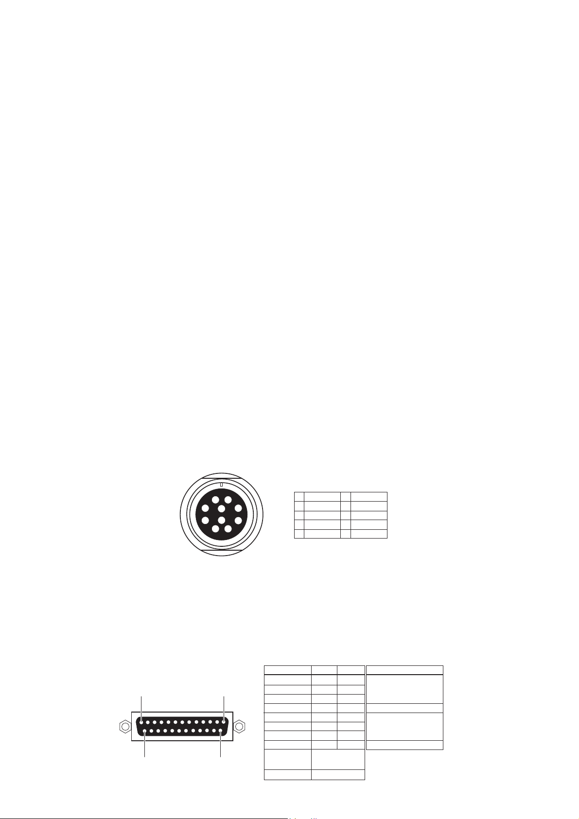
AUX I/O
Connector Hirose RM15TRD-10S, female
Input Balanced audio input for monitoring purpose
Input Impedance 10 kΩ or more
Standard Input Level + 4 dBu
Maximum Input Level + 24 dBu
Output Balanced ST BUSS OUT
Load Impedance 10 kΩ or more
Standard Output Level + 4 dBu / - 10 dBu / - 60 dBu (switchable)
Maximum Output Level + 24 dBu
1
1
8
7
2
9
10
3
465
L OUT +
2
L OUT -
3
R OUT +
4
R OUT -
5
R IN +
10
6
7
8
9
R IN L IN +
L IN GND
GND
DIGIT AL I/O (CH 1 ~ 6)
Connector D-SUB 25-pin
Format
Input Detect either IEC60958 PART 3 (AES/EBU) or IEC60958
PART 2 (S/P DIF) automatically
Output Either IEC60958 PART 3 (AES/EBU) or IEC60958 PART 2
(S/P DIF) is selectable by SETUP menu
Signal
Input 1/2
13
1
1425
Input 3/4
Input 5/6
Input 7/8
Output 1/2
Output 3/4
Output 5/6
Output 7/8
Frame GND
Open
Hot
Cold
1
14
2
15
3
16
4
17
5
18
6
19
7
20
8
21
10, 12, 13, 22,
23, 24, 25
9, 11
Terminal Treatment
Open
GND
4
Page 5
PD-6 Service Manual
TIME CODE INPUT
Connector XLR-3-31 type (Pin 1: GND, Pin 2: HOT , Pin 3: COLD)
Format SMPTE / EBU
Input Impedance 20 kΩ or more
Standard Input Level 2 V p-p
Minimum Input Level 0.25 V p-p
TIME CODE OUTPUT
Connector XLR-3-32 type (Pin 1: GND, Pin 2: HOT , Pin 3: COLD)
Format SMPTE / EBU
Output Impedance 1 kΩ or less
Standard Output Level 2 V p-p
Load Impedance 600 Ω or more
VIDEO/WORD INPUT
Connector BNC (Automatically switchable)
Standard Input Level TTL level (with 75 Ω terminate switch)
WORD OUTPUT
Connector BNC
Standard Output Level TTL level
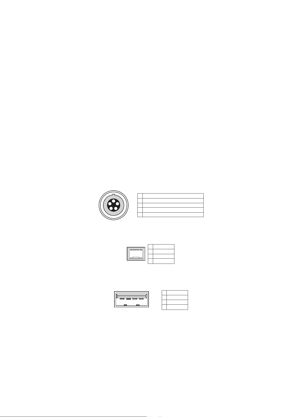
AA TON I/O (optional)
Connector LEMO 5-pin connector
Format ASCII I/O & L TC I/O (parallel with TC I/O)
1
1
2
5
4
3
GND
2
LTC OUT
3
ASCII IN-OUT
4
AUDIO TAPE (not compatible)
5
LTC IN
IEEE1394
Format Comply to P1394a Draft 2.0, 4-pin, for PC connection
1
2314
2
3
4
TPB TPB +
TPA TPA +
USB
Connector Series A receptacle, for connecting a USB keyboard only
1
VBUS
2
2314
D -
3
D +
4
GND
PHONES (MONO / MS / SOLO/ PFL / AUX IN /
ST BUS / 1+2 / 1, 3, 5 + 2, 4, 6 / 3, 5 + 4, 6)
Connector ø 6.35 mm stereo phone jack
Load Impedance 32 Ω or more
Maximum Output Level 200 mW at 32 Ω
SPEAKER (with Drip-proof type sheet)
Impedance 4 Ω
Maximum Output Level 720 mW
5
Page 6
PD-6 Service Manual
SLA TE MIC Switch between 1 kHz reference tone and analog input signal.
SLA TE TONE Switch between internal microphone and analog input signal.
LIMITER
Attack Time About 20 msec
Release Time About 150 msec
Threshold Full Scale level - 6 / - 12 dB (Selectable by SETUP mode)
Ratio 1 : 5 / 1 :2 3 (Selectable by SETUP mode)
Link MONO / 1-2 CH / 1-6 CH (Selectable by SETUP mode)
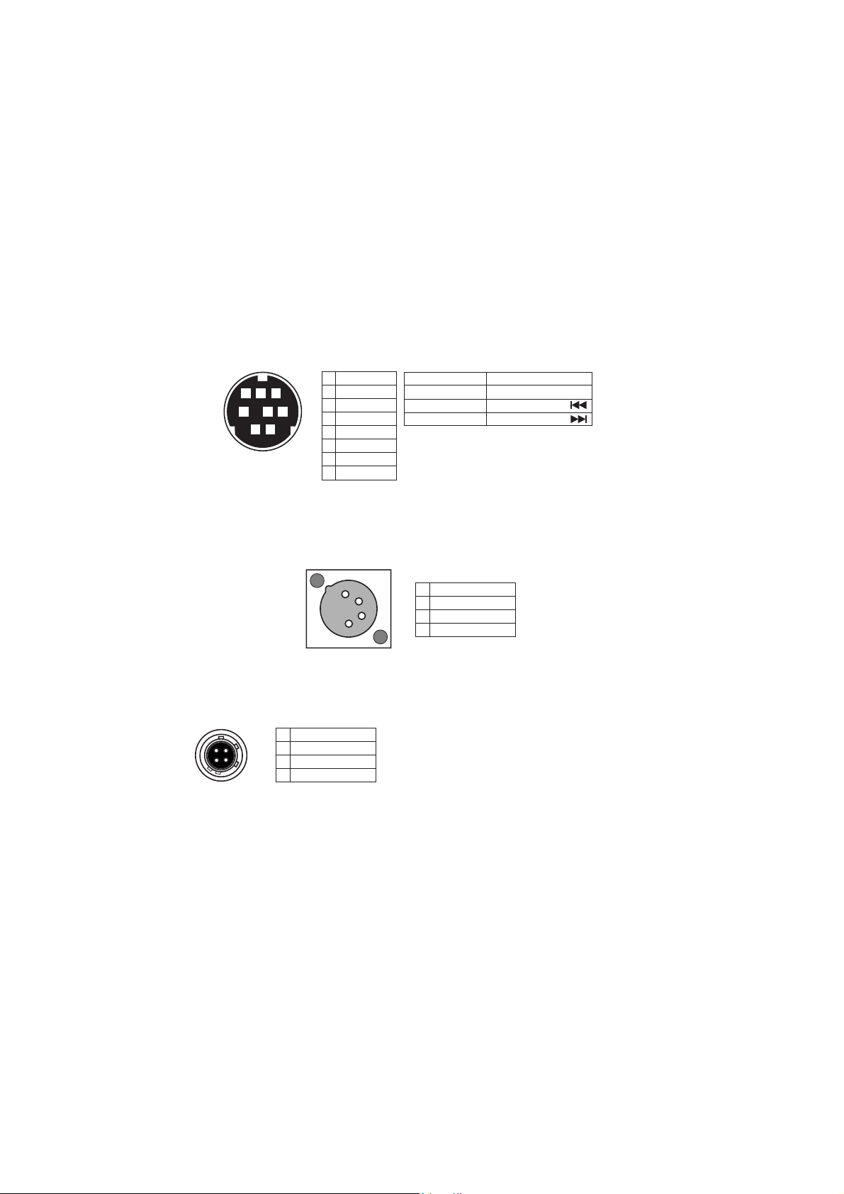
PARALLEL REMOTE
Connector Mini DIN, 8-pin, female
Pin assignment Comply to PD-2 / PD-4. It functions regardless of PANEL
87
2
It can be used for Input / Master fader adjustment.
LOCK key. Connecting a terminal to GND activates a function.
1
PLAY
2
STOP
3
3465
1
REC
4
GND
5
SHIFT
6
REWIND
7
VBATT*
8
FF
SHIFT + STOP
SHIFT + REC
SHIFT + REW
SHIFT + FF
DC + 12 ~ 18 V, MAX 500 mA.
*
DC voltage is output regardless
of PD-6 POWER ON/OFF condition.
CUE
PAUSE
SKIP/CURSOR
SKIP/CURSOR
DC 12 V IN
Connector XLR-4-32 type, male
Pin assignment Comply to PD-2. It functions regardless of P ANEL LOCK key .
4
3
2
1
1
GND
2
NC
3
NC
4
DC +12 ~ 18 V
DC 12 V OUT (x 2)
Connector Hirose HR10-7R-4S, 4-pin, female
Output DC voltage input to DC 12V IN terminal is output.
3
1
42
GND
2
NC
3
NC
4
DC OUT*
DC voltage input to DC IN via protection
*
components are output regardless of
PD-6 POWER ON/OFF condition.
1
RECORD & PLA YBACK
MEDIUM ATAPI (E-IDE) standard 8 cm DVD-RAM drive / disk
RESOLUTION / SAMPLING FREQUENCY 16 bits: 44.1 / 48 kHz
24 bits: 44.1 / 48 / 88.2 / 96 kHz
TRACK MODE
2TRK 44.1 / 48 / 88.2 / 96 kHz
4TRK 44.1 / 48 kHz
5TRK 44.1 / 48 kHz
6TRK 44.1 / 48 kHz
2 + 4TRK 44.1 / 48 kHz
1 + 5TRK 44.1 / 48 kHz
RECORDING TIME (on one side of 8 cm DVD-RAM
disk (about 1.2GB capacity after UDF formatting))
16 bits, 2TRK, 44.1 / 48 kHz About 118 / 108 minutes
24 bits, 2TRK, 44.1 / 48 / 88.2 / 96 kHz About 78 / 72 / 39 / 36 minutes
24 bits, 6TRK, 44.1 / 48 kHz About 26 / 24 minutes
6
Page 7

PD-6 Service Manual
OPERATION
LOCA TE MEMOR Y Cue Point Chunk: 100
EXT / INT BATT key
DISPLAY
DIMENSIONS
WEIGHT
USAGE CONDITION
POWER
INTERNAL NP-1 type battery
EXTERNAL AD-15C
BACKUP BATTERY CR2032 lithium battery (lasting about 3 years)
POWER CONSUMPTION
Black & White LCD (128 x 64 dots)
Bargraph level meter, various time display / mode, setting and
battery remain display
329 (W) x 110 (H) x 245 (D) mm
About 3.4 kg (without NP-1 type battery)
Horizontal / vertical continuous operation
DC 11.5 ~ 18 V (Switchable by INT/EXT SW)
25 W
REGULA TED ENVIRONMENT
ST ANDARD TEMPERA TURE 20 ± 5 °C
ST ANDARD HUMIDITY 65 ± 5 %
ENVIRONMENT AL CONDITION
CHARACTERISTICS GUARANTEED
Temperature 0 ~ + 45 °C
Humidity 30 ~ 70 %
Power Supply Deviation DC 11.5 ~ 18 V
OPERA TION GUARANTEED
Temperature - 10 ~ + 50 °C
Humidity 85 % or less (without water droplet attached)
Power Supply Deviation DC 11.5 ~ 18 V
CHARACTERISTICS
REC / PLA Y FREQUENCY RESPONSE
FS: 44.1 / 48 kHz 20 ~ 20,000 Hz ± 1 dB
FS: 88.2 / 96 kHz 20 ~ 40,000 Hz ± 1 dB
S/N (ADC - DAC, 24 bits, REF: -20 dB, FS; 48 kHz)
(INPUT GAIN: + 4 dBu)
LINE
(INPUT GAIN: -60 dBu, AMP GAIN: 40 dB)
MIC
DYNAMIC RANGE (ADC - DAC, 24 bits, REF: -20 dB,
FS; 48 kHz)
(INPUT GAIN: + 4 dBu)
LINE
THD (ADC - DAC, 24 bits, REF: -20 dB, FS; 48 kHz)
(INPUT GAIN: + 4 dBu)
LINE
(INPUT GAIN: - 60 dBu)
MIC
CLOCK DEVIA TION ± 3 ppm
CHANNEL SEPARATION 90 dB or more at 1 kHz, 0 dB, 24 bits, REF: -0 dB, FS: 48 kHz
PHASE DIFFERENCE 20 ° or less at 20 kHz
CLICK NOISE
Power On/Off - 30 dBVp-p (- 16 dBup-p) or less
SAFETY ST ANDARD
97 dB
84 dB
97 dB
0.008 % or less (at 1 kHz, - 1 dB)
0.010 % or less (at 1 kHz, - 1 dB)
Comply to UES60065, IEC60825-1.
OTHER ST ANDARDS
EMI EN 55011 Class A, EN 61000-3-2/3-3
EMS EN61000-6-1
Specifications and physical appearance are subject to change without notice for product improvement.
7
Page 8
PD-6 Service Manual
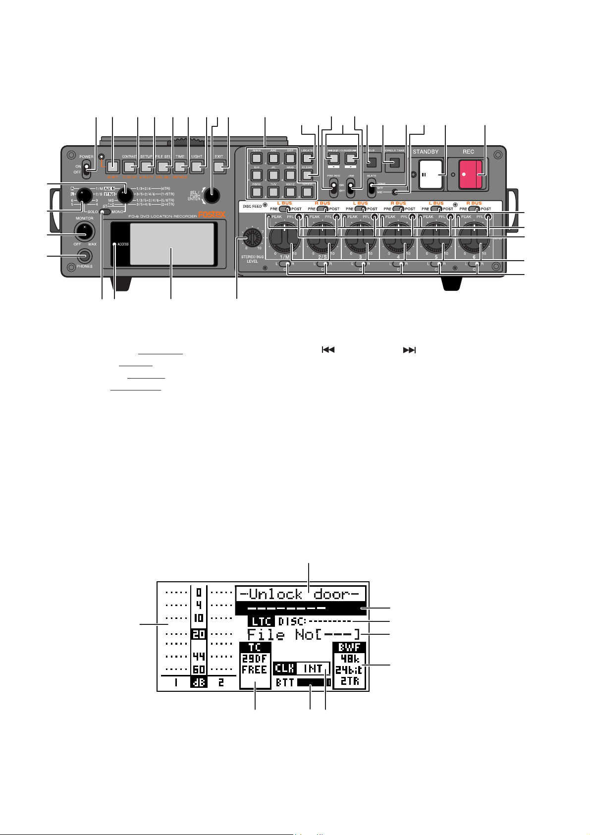
2. CONTROLS, INDICATORS & CONNECTORS
< FRONT PANEL Section >
12 34 56798
16
15
13
12
11 1014
1. [POWER] switch
2. [SHIFT] key / LED
3. [CONTRAST /
4. [SETUP / UTILITY] key
5. [FILE SEL / EDL SEL] key
6. [TIME /
7. [LIGHT] key
8. [EXIT] key
9. [SEL] dial / [ENTER] key
10. LCD display
11. [ACCESS] LED
12. [PHONES] jack
13. [MONITOR] knob
14. [SOLO] monitor select switch
15. Monitor mode select switch
16. [ST/MONO] monitor select switch
17. 10 key
TC SETUP] key
DISP MODE] key
34
17
282027
18 19
18. [LOCATE] key
19. [CLEAR] keys
20. [
21. [CUE] key
22. [CIRCLE TAKE] key
23. [STANDBY] key / Indicator (green)
24. [REC] key / Indicator (red)
25. Slate microphone
26. [SLATE] select switch
27. [JAM] switch
28. [PRE REC] ON/OFF switch
29. [DISK FEED] switch
30. [PEAK] indicator
31. [PFL (Pre Fader Listen)] key
32. [LEVEL] knob
33. [PAN] switch
34. [STEREO BUS LEVEL] knob
21 22 26 23 24
SKIP/CURSOR ] key
25
29
30
31
32
33
< LCD DISPLAY Section >
2
3
1
789
1. Level meter section
2. File name field
3. Time display field
4. Remain field
5. File number field
6. File information field
7. Clock field
8. Battery field
9. TC field
8
4
5
6
Page 9
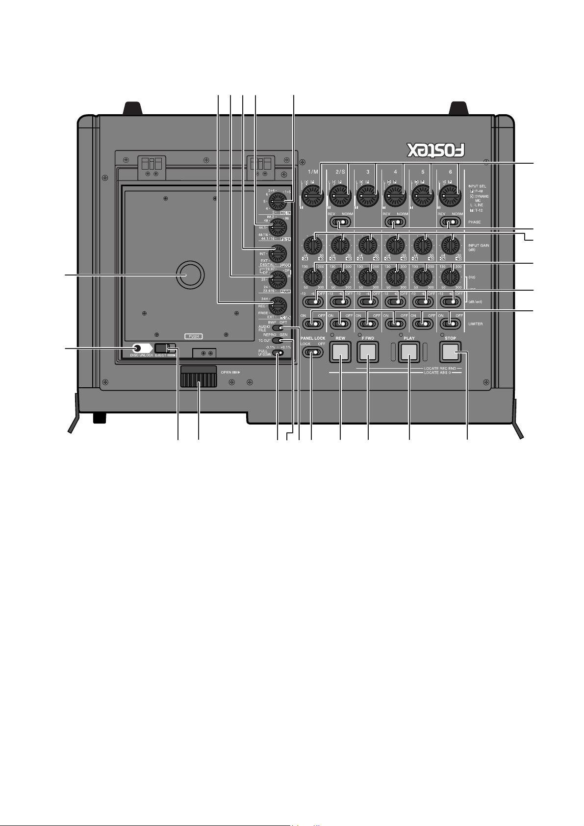
< TOP PANEL Section >
78 6910
11
12
54321
23 22 21 20 19
18
17
16
15
14
13
PD-6 Service Manual
1. [TC GEN] switch
2. [FRAME] switch
3. [CLOCK] switch
4. [FS/24] select switch
5. [REC TR] select switch
6. [AUDIO FILE] select switch
7. [TC OUT] switch
8. [PULL UP/DOWN] switch
9. [OPEN] lever
10. [EJECT] lever
11. [DISC UNLOCK] button
12. Disc tray section
13. [INPUT MODE] switch
14. [PHASE] switch
15. [INPUT GAIN] knob
16. [HPF] knob
17. [HPF] switch
18. [LIMITER] switch
19. [STOP] key / Indicator (green)
20. [PLAY] key / Indicator (green)
21. [F FWD] key / Indicator (green)
22. [REW] key / Indicator (green)
23. [PANEL LOCK] switch
9
Page 10
PD-6 Service Manual
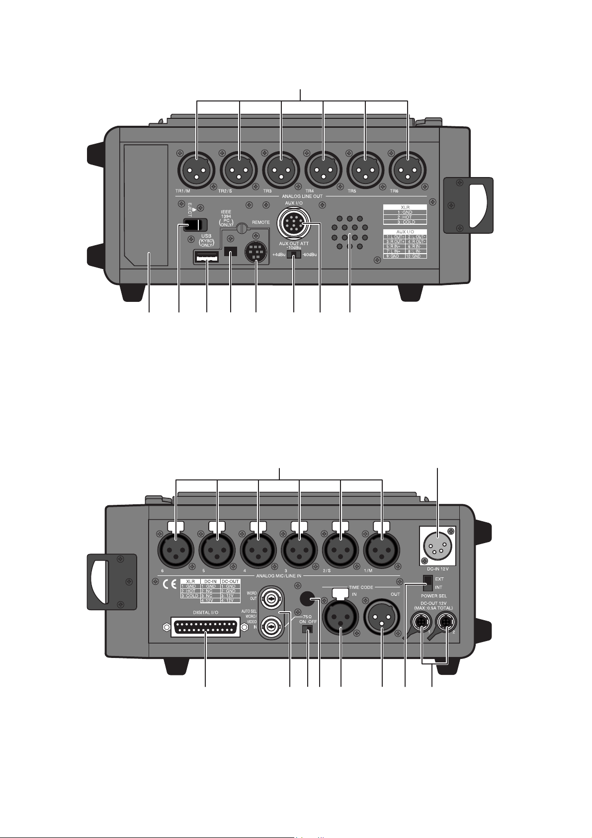
< SIDE PANEL (left) Section >
1
8 7 6 5 43 29
1. [ANALOG LINE OUT] connectors
2. Internal monitor speaker
3. [AUX I/O] connector
4. [AUX OUT ATT] switch
5. [REMOTE] connector
< SIDE PANEL (right) Section >
6. [IEEE1394] connector
7. [USB] connector
8. [EJECT] lever
9. Battery housing
1
2
10
10
1. [ANALOG MIC/LINE IN] connectors
2. [DC-IN 12V] connector
3. [POWER SEL (INT/EXT)] switch
4. [DC OUT] connector
5. [TIME CODE OUT] connector
8 5 4
6. [TIME CODE IN] connector
7. [WORD IN] terminate switch
8. Blank cap for installing options
9. [WORD/VIDEO IN], [WORD/OUT] connector
10. [DIGITAL I/O] connector–
37 69
Page 11
PD-6 Service Manual
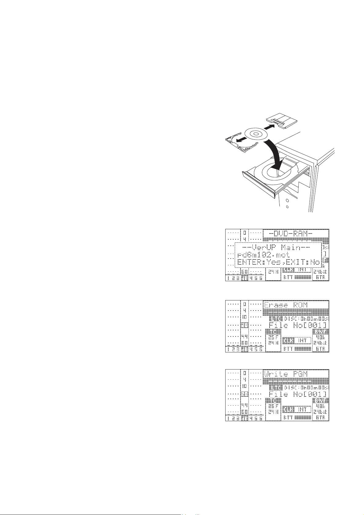
3. SOFTWARE UPDATE
The PD-6 software can be updated by placing a software update file in the top directory tree on the 8 cm DVD-RAM
disk formatted by PD-6. There are two ways of copying the software update file from PC to the disk. Read through the
following procedures for proper software update.
3-1. MAIN PCB Software Update Procedures
3-1-1. There is an ATAPI, IEEE1394 or USB DVD-RAM drive exists in your PC environment;
1) Push down 2 pcs. of lock pins located at the lower left side on both
A and B sides of 8 cm DVD-RAM disk by using the tip of a ball
point pen, etc. Then, spin and move the lock pins out and around.
2) Take out the 8 cm DVD-RAM disk out of the cartridge and place
it in the indent of the DVD-RAM drive tray.
3) Extract the WinZip compressed software file “PD6VXXX.zip” and
copy the newly created software update file “pd6mXXX.mot” to
the top directory tree of the DVD-RAM disk. (“XXX” indicates
the software version number. If the software version is V1.02, the
software update file name will be “pd6m102.mot”.)
4) After copying the software, take out the 8cm DVD-RAM disk, put
it back to the cartridge and load it to the PD-6 DVD-RAM drive.
When putting a bare DVD-RAM disk back to the cartridge, be
sure that the side A of the disk conforms with the cartridge’s A
marking.
5) Power on PD-6. In the initialize stage, PD-6 automatically finds
the software update file placed in the top directory tree and is put
into the software update mode. The LCD example on the right
indicates that the PD-6 MAIN software is going to be updated to
V1.02 using the software file “pd6m102.mot”.
6) In the condition that the LCD example on the right is displayed,
press the ENTER key (knob) to update the software.
PD-6 starts updating the MAIN software. The LCD shows “Erase
ROM” (flashing) and then “Write PGM” (flashing).
7) After updating the software is completed, PD-6 is automatically
put initialized, booted up again and is put into the software update
mode. Press the EXIT key. (Depending on the current software
version, there is a case that powering off and then back on PD-6
might be required. Also there is a case that the display contents
differ from those listed in this page.)
8) Confirm the software version by the “Version” SETUP menu explained later.
DVD-RAM cartridge
DVD-RAM Drive
11
Page 12
PD-6 Service Manual
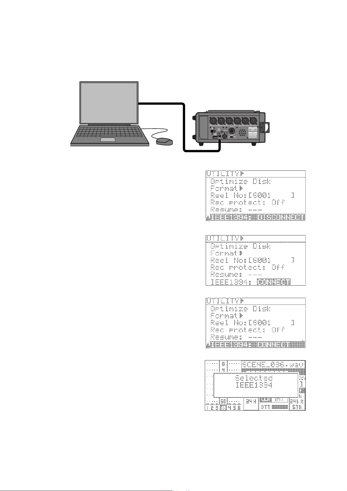
3-1-2. There is no ATAPI, IEEE1394 or USB DVD-RAM drive exists in your PC environment;
NOTE:
As mentioned in the PD-6 owner’s manual, depending on the operating system running on your computer, an
IEEE1394 driver software must be installed in your computer to allow to recognize the UDF formatted PD-6
DVD-RAM disk as a rewritable medium prior to the software update.
1) Select the IEEE1394 Utility menu and press the ENTER knob.
Then, turn the ENTER knob to right to select “CONNECT” and
press the ENTER knob again.
By putting PD-6 into the IEEE1394 mode, all functions are
disabled.
2) Connect the IEEE1394 cable between PC (Desktop PC: 6-pin,
Laptop PC: 4 or 6-pin) and PD-6 (4-pin) IEEE1394 ports.
3) Wait for a while until PC recognizes PD-6 with 8 cm DVD-RAM
disk loaded as an external rewritable removable drive / disk.
4) Extract the WinZip compressed software file “PD6VXXX.zip”
and copy the newly created software update file “pd6mXXX.mot”
to the top directory tree of the DVD-RAM disk. (“XXX” indicates
the software version number.)
5) After copying the software, select PD-6 (FOSTEX FX-FIRE IEEE
1394 SBP2 Device - (*)) and remove it from PC. (*: Drive No. on
your PC)
6) Disconnect the IEEE1394 cable from the PC / PD-6 and turn off
the IEEE1394 mode.
In the initializing stage, PD-6 automatically finds the software
update file placed in the first directory tree and is put into the
software update mode.
7) Press the ENTER key (knob) to update the software.
PD-6 starts updating the MAIN software. The LCD shows “Erase
ROM” (flashing) and then “Write PGM” (flashing).
8) After the software update is completed, power off PD-6 and then
back on. (Depending on the software version, there is a case that
PD-6 is automatically initialized and is booted up.)
9) Confirm the software version by the “Version” SETUP menu.
12
Page 13
PD-6 Service Manual
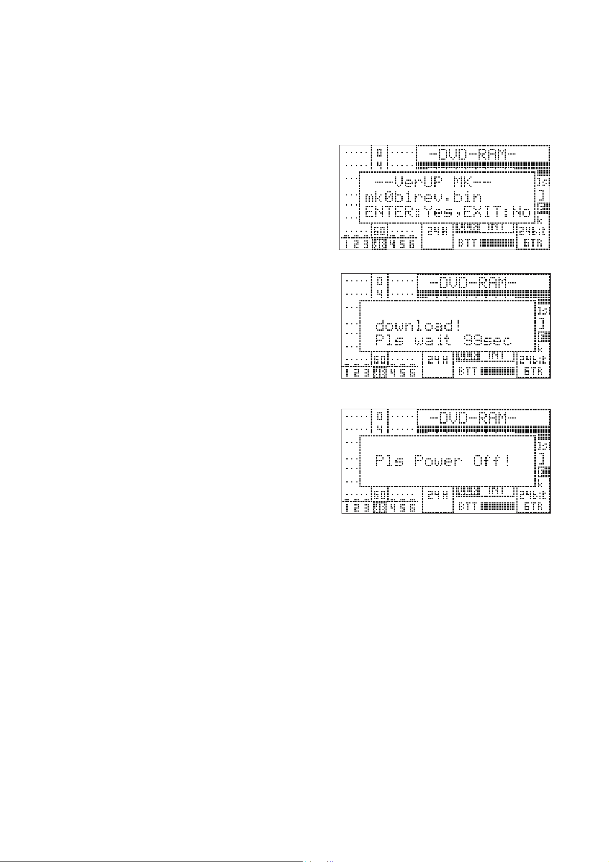
3-2. DVD-RAM Drive Firmware Update Procedures
There are two firmwares for DVD-RAM drive, which can be updated by a similar method explained before. Although
the DVD-RAM drive firmware update will not occur as many times as the MAIN PCB software update, read through
the following explanation for correct update procedures.
1) Copy the DVD-RAM drive firmware update file
“mkXXXrev.bin” to the top directory of the DVD-RAM
disk either by direct software file copy onto a 8 cm DVDRAM bare disk or by putting PD-6 into the IEEE1394
mode and connecting to PC.
2) In the initialize stage, PD-6 automatically finds the
firmware update file in the top directory tree and is put
into the update mode. The example on the right indicates
that there is a firmware update file “mk0b1rev.bin” exists
in the top directory tree.
3) Press the ENTER knob to update the DVD-RAM drive
firmware.
The firmware update remaining time starts counting down.
It will take about 100 seconds (1 minute and 40 seconds)
to complete the firmware update.
4) After the software update is completed, the message “Pls
Power Off!” will appear on the PD-6 LCD. Power off
PD-6 and then back on. (Depending on the software version, there is a case that PD-6 is automatically initialized
and is booted up again.)
5) Select “Reset setup memory” in the SERVICE menu ex-
plained later in this manual, press the ENTER knob and
press the ENTER knob again while “SURE?” is flashing
on the LCD to reset the memory.
6) Confirm the software version by the “Version” SETUP
menu.
13
Page 14
PD-6 Service Manual
4. SERVICE MENUS
Various Service menus in addition to the normal SETUP menus are
available on PD-6 in order to judge if the unit is working correctly.
4-1. Accessing to Service Menus
1) Power on PD-6.
2) While holding down the STOP key, press the SETUP key.
The Service menus are displayed in addition to the normal menus.
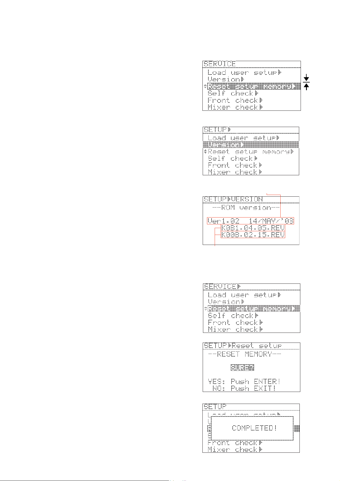
4-2. Software & Firmware Version
Although this is not a Service menu, the PD-6 MAIN software
version as well as the DVD-RAM drive firmware version can be
confirmed. To check, select the “Version” menu and press the
ENTER knob.
There are three versions displayed in the “Version” menu.
The top one (“Ver1.02 14/MAY/’03” on the right example) is the
PD-6 MAIN software version number. The middle one
(“K0B1.04.05.REV” on the right example) and the bottom one
(“K00B.02.15REV on the right example) indicate the DVD-RAM
drive firmware version number.
If the new MAIN software and / or the DVD-RAM drive firmware
are sent from us, check the version number in this menu after updating
the software / firmware.
MAIN software version
and programming date
DVD-RAM drive firmware version
and programming date
MENU
SETUP
MENU
SERVICE
4-3. Reset setup memory
This menu is used for resetting various parameters in the SETUP
menus to the default value such as “Ref.level” to “-20dB” and “Peak
hold” to “3sec”. Also executing the MEMORY RESET is nececsary
after updating the MAIN software.
To reset the setup memory, select the “Reset setup memory” Service
menu and press the ENTER knob. Then, while “SURE?” is flashing,
press the ENTER knob again. After the “Completed!” message
appears for a short while, the LCD returns to the SETUP / SERVICE
menu select display.
CAUTION:
Every time the MAIN software is updated, execute the “Reset setup
memory”.
14
Page 15
PD-6 Service Manual
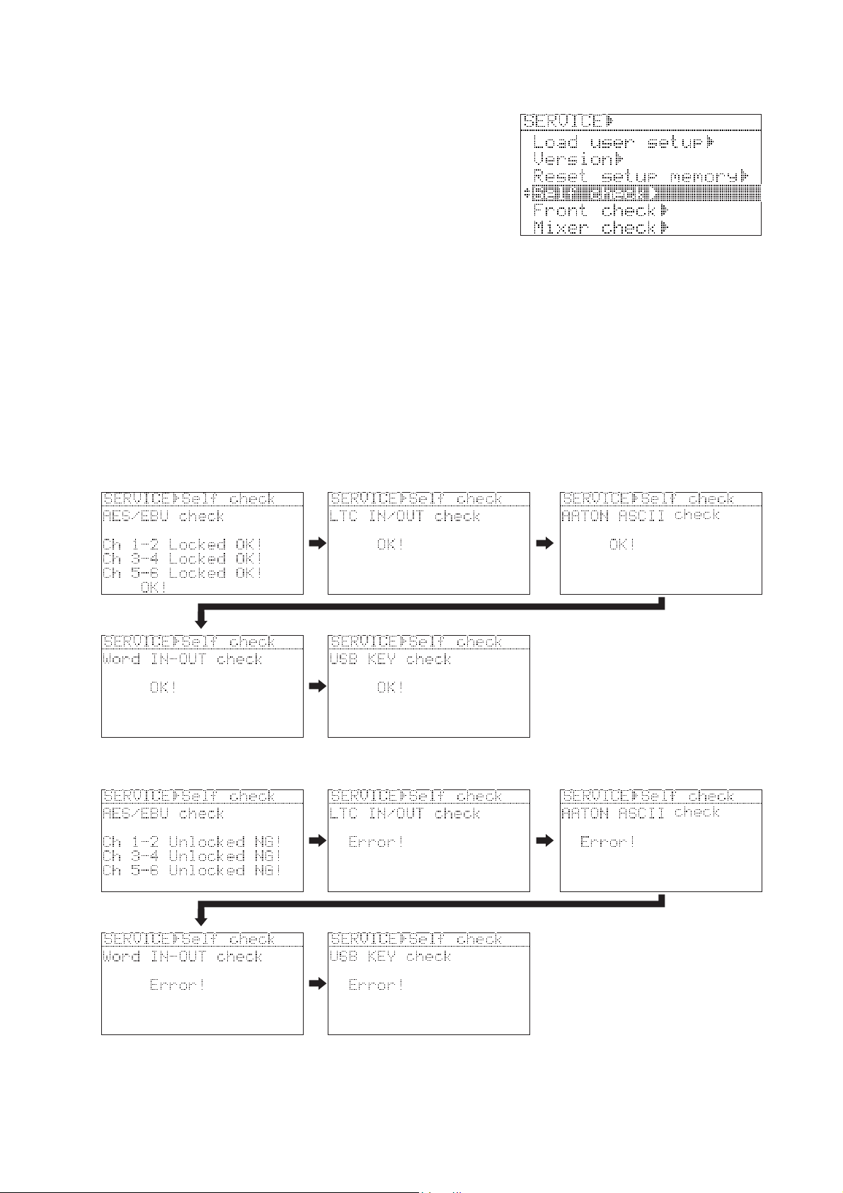
4-4. Self Check
The Self Check Service menu checks if the following circuits works
properly in order.
•AES/EBU IN and OUT circuit
• LTC IN and OUT circuit
• AATON ASCII circuit
• WORD IN and OUT circuit
• USB circuit
Preparation:
Before executing the Self Check menu, the following PD-6 connectors must be connected.
• AES/EBU CH 1-2/3-4/5-6 INPUT and CH 1-2/3-4/5-6 OUTPUT using a D-SUB 25-pin <-> XLR male x 4 / XLR
female x 4 cable such as HOSA DBK-258
• LTC IN and OUT using a XLR male <-> female cable
• WORD IN and OUT using a BNC <-> BNC cable
• USB keyboard
To execute, press the ENTER knob in the condition that “Self Check” is highlighted. PD-6 automatically checks
the above mentioned circuits. In order to skip one or some of the above checking items, press the EXIT key.
• Display example when PD-6 circuit works properly:
• Display example when PD-6 circuit does not work properly:
15
Page 16
PD-6 Service Manual
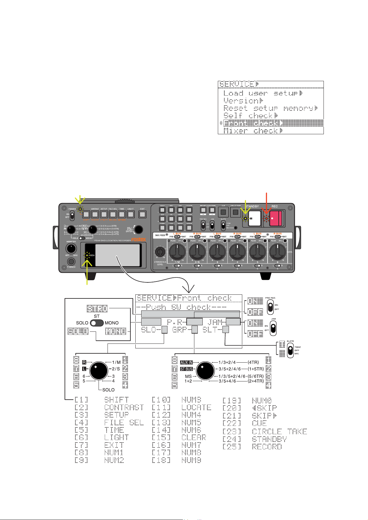
4-5. Front Check
This menu checks if the toggle / rotary / tact switches and LEDs on the PD-6 front panel are correctly working. To
check the switches and LEDs operation on the front panel, select the “Front Check” Service menu and press the
ENTER knob. To get out of this menu, press the ENTER knob again.
• Tact switches (25 pcs. in total)
The switch number 1 through 25 and the corresponding name (i.e.:
[1] SHIFT) are displayed on the LCD every time the tact switch is
pressed.
• Rotary switches (2 pcs. in total)
The number 1 through 8 is displayed on the LCD depending on the
SOLO and MONITOR rotary switch position.
• Toggle switches (4 pcs.)
STRO (stereo) / MONO / SOLO, ON / OFF and T / none (blank) are displayed on the LCD depending on the
SOLO monitor select / PRE REC / JAM / SLATE select toggle SW position respectively.
• LEDs
The REC LED flashes in RED and the STANDBY, SHIFT and ACCESS LEDs flash in GREEN.
Flash in green
Flash in green
Flash in red
Flash in green
16
Page 17
PD-6 Service Manual
Flash in green
Flash in green
Flash in green
Flash in green
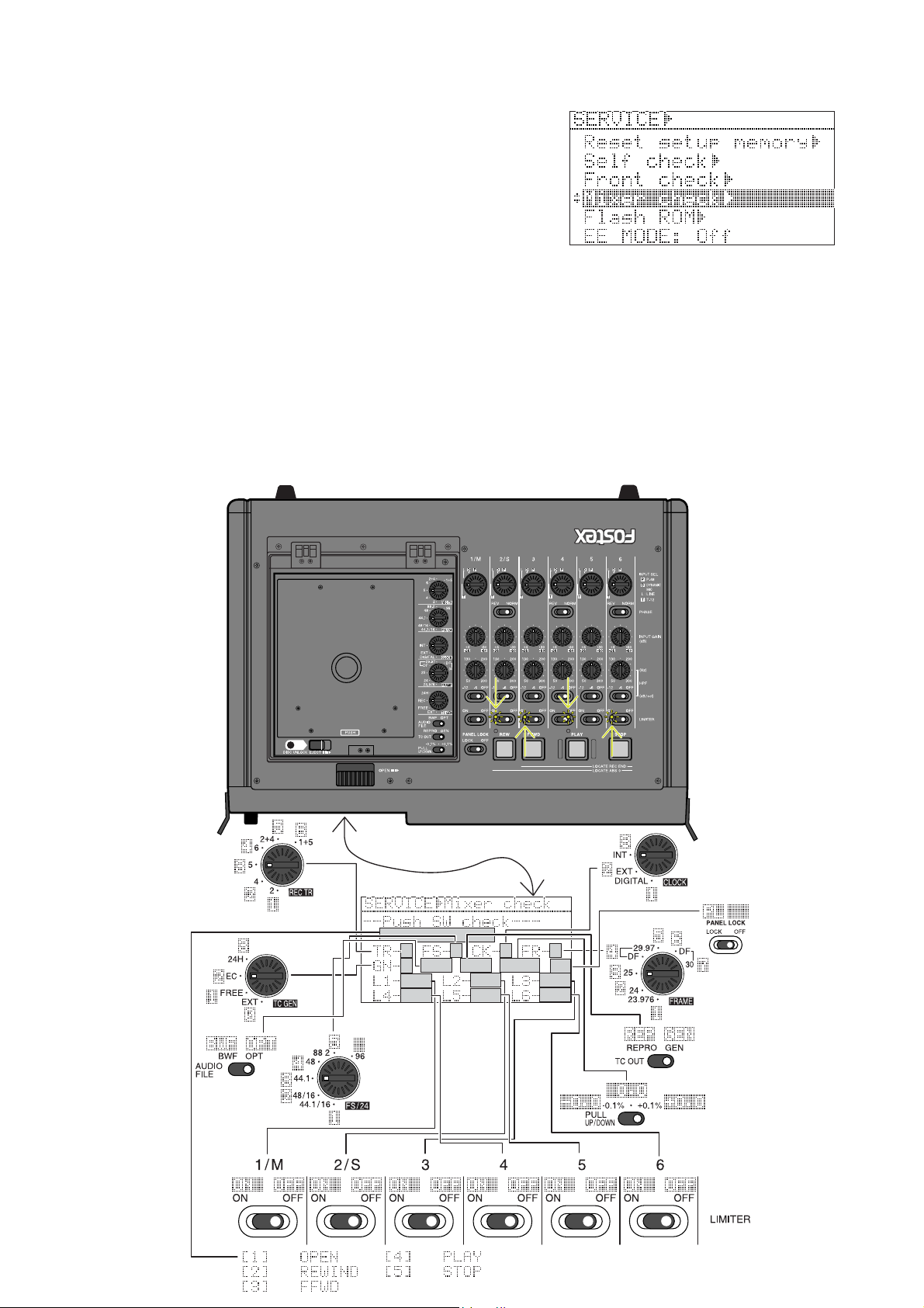
4-6. Mixer Check
This menu checks if the toggle / rotary / tact switches and LEDs on
the PD-6 top panel are correctly working. To check the switches
and LEDs operation on the top panel, select the “Front Check”
Service menu and press the ENTER knob. To get out of this menu,
press the ENTER knob again.
• Tact switches (5 pcs. in total)
The switch number 1 through 5 and the corresponding name (i.e.:
[1] OPEN) are displayed on the LCD every time the tact switch is pressed.
• Rotary switches (5 pcs. in total)
The number is displayed on the LCD depending on the REC TR, FS/24, CLOCK, FRAME and TC GEN rotary
switch position.
• Toggle switch (10 pcs.)
BWF / OPT, REPRO / GEN, -0.1 / 0.0 / +0.1 and ON / OFF are displayed on the LCD depending on the AUDIO
FILE, TC OUT, PULL UP/DOWN, CH1 ~ 6 LIMITER ON/OFF and PANEL LOCK toggle SW position
respectively.
• LEDs
The REWIND, F FWD, PLAY and STOP LEDs flash in GREEN.
Flash in green
Flash in green
Flash in green
Flash in green
17
Page 18
PD-6 Service Manual
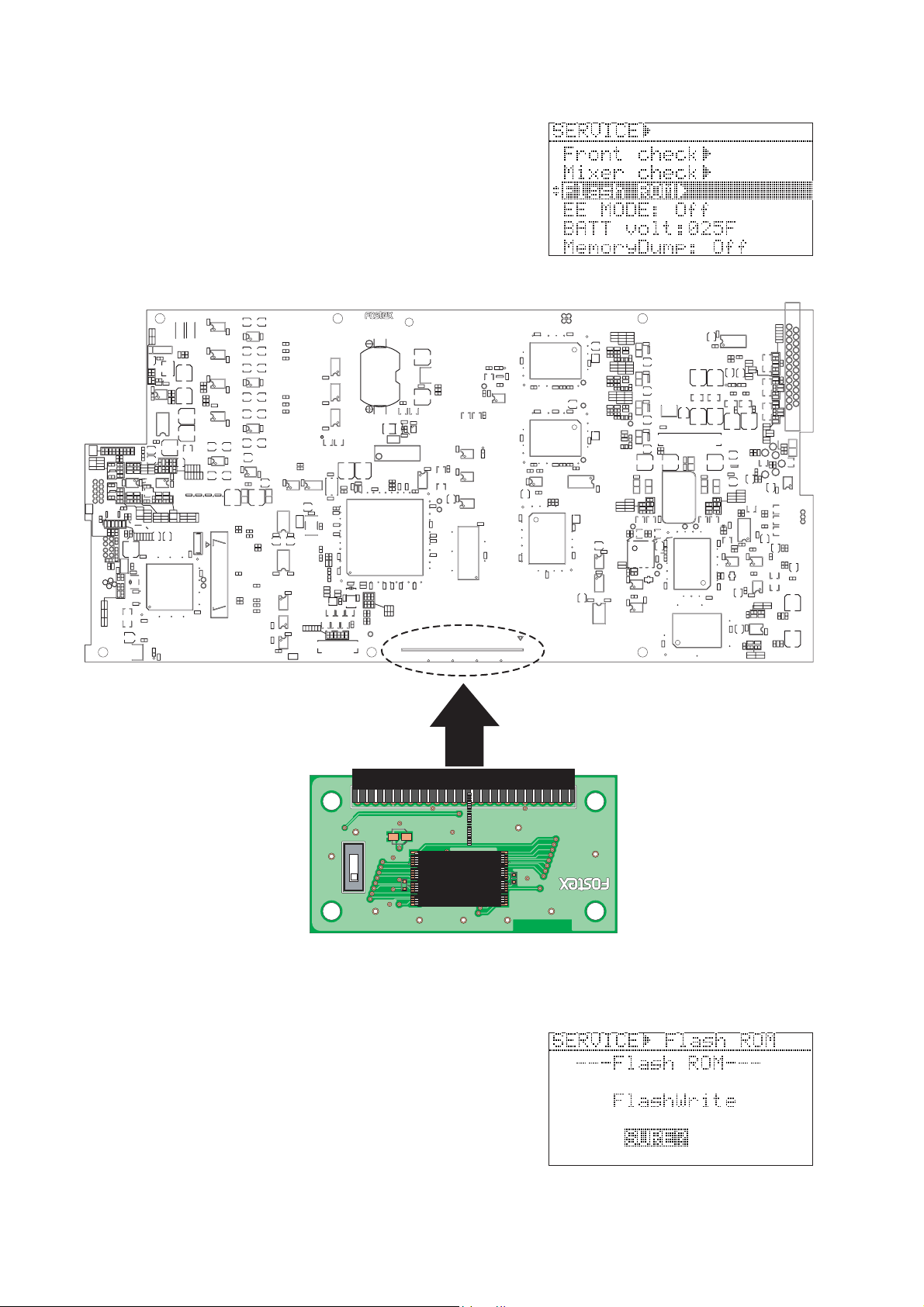
4-7. Flash ROM
There is a Flash ROM Card PCB prepared for the PD-6 MAIN
PCB. The Flash ROM Card PCB (P/N: 8274354000) is used if
something wrong happens during software update (i.e. power
shutdown, blackout). The Flash ROM Card PCB allows to boot up
PD-6, copy the system software in the Flash ROM Card PCB to the
Flash ROM on the PD-6 MAIN PCB using this “Flash ROM”
Service menu. Furthermore, you can rewrite the programming inside
the Flash ROM on the Flash ROM PCB.
U711
C744
1
C746
1
C750
1
U710
1
C809
C734
1
E1152
E1151
C771
+
+
C736+C737
U717U718U719U720
+
J1152
9
9
U712
9
U713
9
C824
8
EXT DRIVE
U703
C745
C706
1
C742
C747C749
C741
U702
1
C740
C739
U701
C772
C702 C704
1
C738
U706
C733
C762
1
R862
+
L701
C825+C826
R1188
W1151
W1153
R1156
R1192
+
+
8
W708
+
W707
+
W706
C723
C722
+
+
8
C703 C705
+
+
C721
C720
+
+
8
C701
+
+
C719
+
C770
5
C763
C766
+
C79
L702
13
U13
W1152
C66
R1175
C90
+
R1158
13
R1157
C89
R1152
C1152
1
R1154
R1155
8
R1153
C1151
1
C62
R1176
W705
W704
W703
R67
R66
U14
1
9
1
8
RED
U19
C76
8
1
1
J5
1
2
1
C64
2
+
C85
U18
1
C87
U1151
U1154
R47
R48
R58
C71
U12
POWER
J902
11
U35
C82
1
11
U24
B1
1
C74
11
U27
C75
1
U37U38
E5
C21+C22
C14
+
11
C50
C24
C29
1234
R17
X1
C15
181
+
C5
R18
C3
C42
X5
C52
R51
C44
34
R19
C17
R68
R69
W1
C10
C12
R20
C18
240
W2
1
C26
C92
C97
C84
C83
C94
R64
C23
R70
D5
D6
R49
R50
R59
D8
D4
D7
19
JTAG
J2
C25
C28
C9
C7
X2
C27
U41
R4
R65
C13
+
15
C20
+
C19
R37
D1
D2
C53
C51
X3
U7
R34
C54
J1
12
8
1
C40
R3
14
7
C96
TMS
TDI
TDO
TCK
1
/TRST
/RESET
/ASEBRK
U29
R2
C38
C49
R8
R25
R33
120
C36
61
U6
C33
60
C35
C37
C39
C47
R12
R13
R11
R6
R7
R5R9R10
49
502
R863
R771
R858
R859
C755
R856
U721
R772
R773
C760
C757
W701
1
+
J702
+
2
C761
R766
C819
C820
R784
+
5
R785
R756
R759
R786
C821
R783
R765
R782
C751
1
R781
U723
C822
R755
+
C773
U716
+
W702
C774
C777
U907
52 13
3
R1184
R1182
C1155
610
U908
64
78
4
1
R1183
R1181
R1185 R1187
C803
R842R843
R819
R820
C789
1
U705
C805
C806
8
R934
R840
R835
R933
Q706
R836
R837
R839
R932
R838
R1189
C937
C939
C940
C941
R1190
C1172
C1160
C1157
+
108
R1177
C1181
C1159
C1156
X1004
2
C1182
C1154
43
1
21
D903 D904
C1164
+
R928
C932
U904
L801
~
L809
R822
R815
R816
Q705
R817
R818R821
51
L910
~
L916
R931
+
+
C804
R807R811
R806
C786C787
8
C796C797
R826
C799
R827R829
C1165+C1166
+
C938
C942
U1152
D905
C930
15
1
U707
R823
D703
R841
20
+
C794
R834
R828
C798 C800
C807C808
C779 C780
C781 C782
R803
R800 R801
J1154
(FIRE-USB1 LOAD)
DGND
D+
D-
C1161
80100
U714
U704
R824
R833
R825
R830
R831 R832
C795
R804
USB
4
1
72
C1162
40
C1163
36
PCB,MAIN,PD-6
U381
C395
D3
U5
E3
E4
C34
C48
C43
C41
R14
1
U3
50
C2
U2
R16
E1
R21
R22
R23
U25
R39
U28
+
C31
28
U10
8
C1
R1
1
U26
U21
U1
R41
C78C11
1
1
C57
1
C60
J3
C196
8
U181
50
U40
D10
8
R1007
U1005
U16
9
C1002
U9
1
C1018
10
U1002
20
C59
C1016
1
EXT ROM
C724
Front Side
C743
1243
U902
R948
+
D918 D919
C951+C952
POWER
R1059
C1094
U1020
L1013
C1086
20
C908
R911
C924
9
C923
R910
C914
R946
R921
C909
R913
C926
C925
R922
R912
R924
C915
1
1
Q904
D906 D909D910D912 D915D916
W903
W904
C905
R905
C918
C917
R918
R1066
L1019
R904
3
C911
C1120
4
C1119
R1065
L1018
2
+
R1070
1
1
R1048
D1006
U1007
+
R1035
C1068
R1031R1032
R1060
8
C1024
R1009
8
C1095
+
C1109
+
R1046
D1007
R1072
U1030
R1052
5
6
C1116
+
R1073
R1074
1
+
D1008
C1089
C1088
R1077
13
D1009D1010D1011
R1076
R1078
U1026
+
C1090
C1112
L1014
R1067
R1039
1
C1091
R1038
8
2H
R1061
R1071
3C
C1079
L1015
1
R1040
5
R1043
C1098
R1047
5
C1099
C1102
R1054
C1113
+
U1028
D1005
1
R1062
G
S4
+
1
D1004
U1029
R1055
R1064
C1103
C1107
R1063
C1115
C1108
L1017
C1118
1
R1069
U1031
G
C
H
C1110
+
C1114
C1117
L1016
R1068
C904
C382
C384
10
30
20
1
C385 C387
R386
C391
R382 R383
R381
R385
C389
L381
C381
C388
R384
+
R387
C285 C287
R282 R283
R281
C397
E381
60
80
R389R390
R391
C396
C181
C182
C183
C195
30
20
R191
60
C197
R1008
8
C1021
+
1
R1004
R1075
100
L1003
R1005
30
50
C1004
1
C185 C187
R182 R183
R181
E281
10
1
100
R187
C184
80
R189R190
L1004
1
9
U1004
C1019
80
R1006
C73
C1006
+
60
C68
1
C1017
U30
9
1
C93
U20
11
+
C65
C63
C67
1
U15
13
R1002
C1008
C1007
C1011
R285
R284
R185
R184
E1001
R1022
C1041 C1044
R1019 R1020
E1002
X1001
C1123
R1037
U1019
R1010
U382
1
R388
C386
+
R286
C291
C289
L281
C288
U282
1
C286
+
R186
C191
L181
C189
C188
U182
1
C186
+
R188 R288
15
C1009
L1001
1
U1032
R1001R1003
1
W902
+
C1005
W901
+
C1049
1
C1054
C1053
L1006
L1007
X1002
R1023
C1046
C1060
U1009
U1010
R1027
U1011
D1001
D1002
2
C1052
U1012
1
R1028
R1024
R1012
3
70
6
C1025
E1006
R1034
E1005
C1022
L1005
C1048
1
U1008
C1030
C1124
1
52
U1034
U1024
C1082
C903
+
1
R903
R947
C947+C950
C949
C948
+
+
U903
1
R943 R944
+
Q9011Q902
Q903
+
+
C931
C929
C935+C936
J901
C1028
11
C1071
+
+
C1055
L1008
C1056
C1032
C1075
C1034
L1011
L1012
R1033
C1064 C1066
U1015
E1003
80
51
64
1
U1016
40
50
D1003
E1004
R1036
C1042
30
U1017
C1026
C1045
20
1
R1011
C1029
1
C1051
100
C1035
90
33
32
19
MAIN PCB
Flash ROM card PCB
50
49
(FLASH)
+
C1
25
C2
INT
S1
EXT
J1
TC58FVT160FT-10
TOSHIBA K29284
Connector J3 Location on MAIN PCB
• Rewriting the Flash ROM Program on Flash ROM Card PCB
NOTE:
In order to rewrite the Flash ROM program on the Flash ROM Card
PCB, PD-6 which works in good order must be prepared.
1) Power off PD-6 and disconnect the power cable from the AC adapter
AD-15C or remove the NP-1 type internal battery.
2) Open up the bottom cover.
3) Set the SW S1 on the Flash ROM PCB to “INT” side and plug it
into the 50-pin connector J3 on the MAIN PCB.
R1
1
U1
PCB,FLASH-ROM CARD
2
1
8252510001
18
Page 19
PD-6 Service Manual
4) Connect the AC cable from the AC adapter AD-15C or insert the
NP-1 type battery.
In this condition, PD-6 is booted up using the software program
inside the Flash ROM on the PD-6 MAIN PCB.
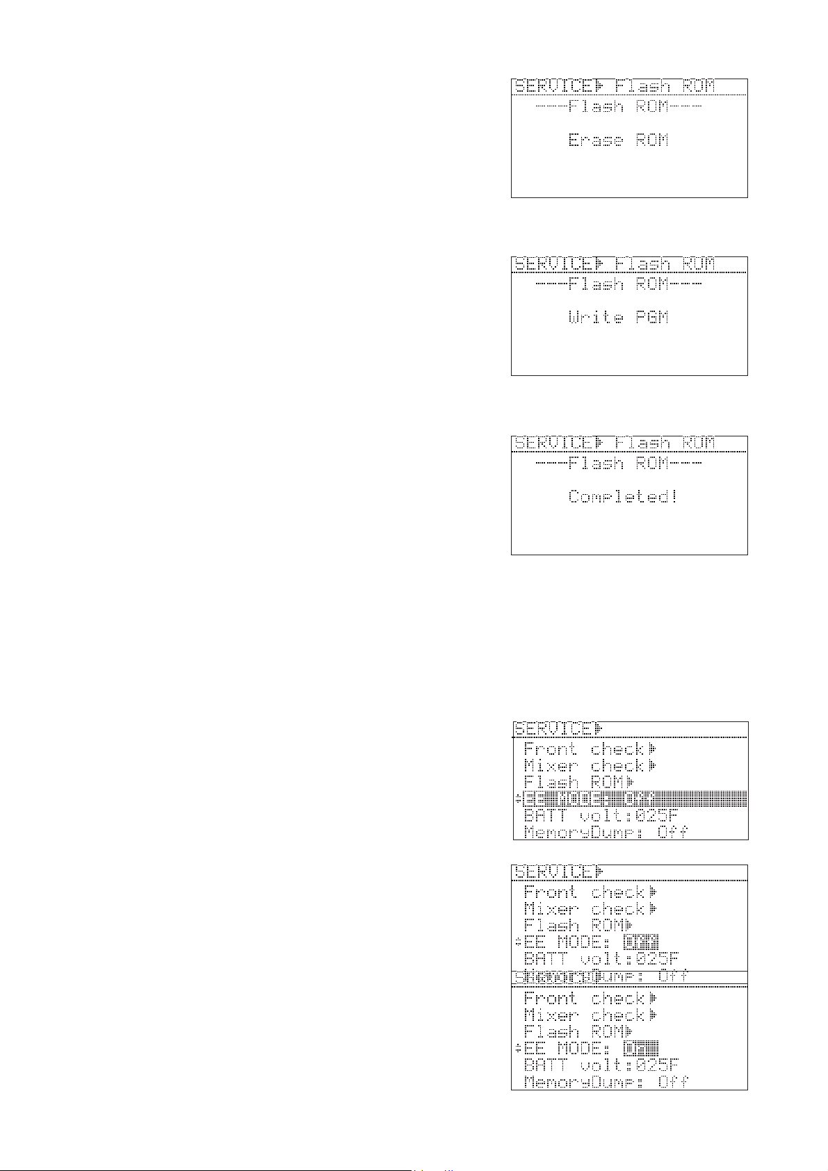
5) Select the “Flash ROM” Service menu and press the “ENTER” knob.
6) While “SURE?” flashes, press the ENTER knob.
“Erase ROM”, “Write PGM” and then “Completed!” will appear
on the PD-6 LCD in order.
7) Press the EXIT key or ENTER knob to go back to the SETUP /
SERVICE menu select display.
With the above procedures, the program inside the Flash ROM on
the PD-6 MAIN PCB is transferred to the Flash ROM on the Flash
ROM Card PCB.
• Rewriting Flash ROM Program on the MAIN PCB
1) Power off PD-6 and disconnect the power cable from the AC adapter
AD-15C or remove the NP-1 type internal battery.
2) Open up the bottom cover.
3) Set the SW S1 on the Flash ROM PCB to “EXT (FLASH)” side
and plug it into the 50-pin connector J3 on the MAIN PCB.
4) Connect the AC cable from the AC adapter AD-15C or insert the
NP-1 type battery.
In this condition, PD-6 is booted up using the software program
inside the Flash ROM on the Flash ROM PCB.
5) Select the “Flash ROM” Service menu and press the “ENTER” knob.
6) While “SURE?” flashes, press the ENTER knob.
“Erase ROM”, “Write PGM” and then “Completed!” will appear
on the PD-6 LCD in order.
7) Press the EXIT key or ENTER knob to go back to the SETUP / SERVICE menu select display.
With the above procedures, the program inside the Flash ROM on the Flash ROM Card PCB is transferred to the
Flash ROM on the PD-6 MAIN PCB.
4-8. EE Mode
By turning on the EE mode, the A-to-D and D-to-A converters
circuitry on PD-6 are directly connected. This menu is used for
measuring the frequency response, S/N and Dynamic Range value
for Quality Control purpose.
• Turning on the EE mode
1) Press the ENTER knob while the EE mode menu is selected.
The default setting “Off” flashes.
2) Rotate the ENTER knob to change the setting to “On” and press the
ENTER knob again.
NOTE:
The EE mode on / off condition will not be battery backed up. Even
if the PD-6 power is turned off with “EE MODE: On” condition,
powering on PD-6 again will initialize the EE mode setting to the
default value (Off condition).
19
Page 20
PD-6 Service Manual
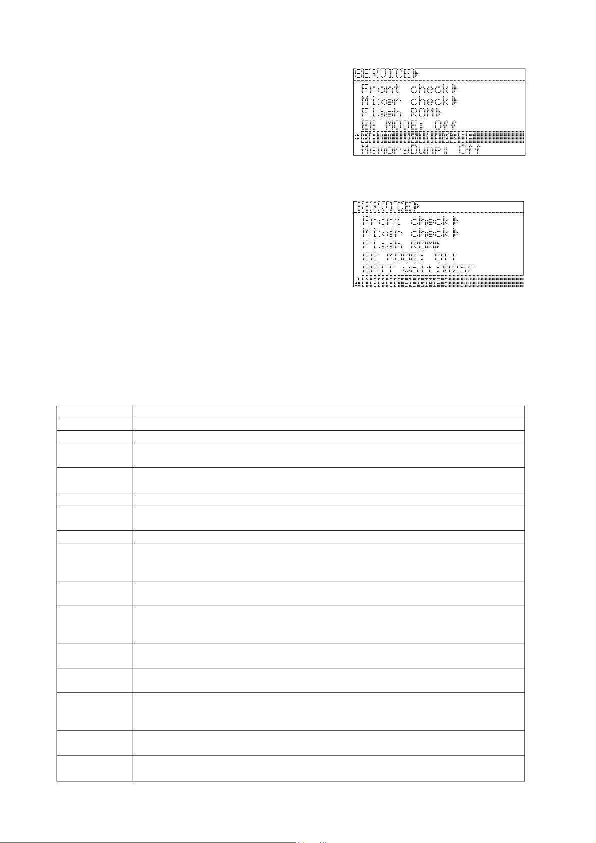
4-9. BATT volt (Battery Voltage)
This menu monitors either the AC adapter DC voltage (POWER
SEL SW setting: EXT, EXT_PWR_DETECT fed to pin-238 (AN6/
PTL6/DA1) of CPU U6 (SH7727)) or the NP-1 type battery DC
voltage (POWER SEL SW setting: INT, INT_BATT_DETECT fed
to pin-239 (AN7/PTL7/DA0) of CPU U6). If the DC voltage is
around 15V, the 4-digit hexadecimal value will be around 0240.
4-10. MemoryDump
This menu is only utilized at our manufacturer and has nothing to
do with servicing PD-6.
5. ERROR CODE / ALERT LIST
The Table below indicates the error code number and corresponding description. Since the error code list is basically
designed for our engineers to improve the software, the description is quite technical. If you find PD-6 displaying the
error codes, we encourage you to update the software to the latest one first. In case updating the software does not solve
the problem, we would like you to contact us.
Error / Alert
ERROR=0
ERROR=1
ERROR=20
ERROR=21
ERROR=83
TimeOut Read!
Read Error!
Disc Error! Write
Write Error
Event Over!
Diagnoses write!
Rec Timeout Err!
Rec Caution!
File Size Over!
Write Error!
Not defined.
Trying to access the sector address other than the accessible region on disc.
The file size exceeded the specified capacity (2GB or 4GB) while in REC mode. This error code will be
deleted on V1.03 software onwards.
Shortage of capacity while in REC mode occurred. This error code will be deleted on V1.03 software onwards.
Failed to Block-Erase while in the Flash ROM SAVE (writing) mode.
Time-out occurred when reading out data. Drive malfunction, disc failure, dust & dirt on the DVD-RAM
disc.
An error occurred when reading out data. Disc failure, dust & dirt on the DVD-RAM disc.
Time-out occurred when writing in data. After this error message appears, PD-6 initializes the DVD-RAM
drive. Disc failure, dust & dirt on the disc. Changing to a new disc or physical-format a disc is highly
recommended.
An error occurred when writing in data. Disc failure, dust & dirt on the DVD-RAM disc. Changing to a new
disc or physical-format a disc is highly recommended.
Too much disc fragmentation (discontinuous sector region) exceeding the UDF management while recording an audio files. The disc on which editings were executed on PC were used on PD-6. This error rarely
occurs. The cause could be other than PD-6.
An error list information "file name.dia" was created because an error occurred when writing in audio data
on the disc.
A cache buffer overflowed and audio files could not be completed recorded on the disc. Dust & dirt on the
disc, failure sectors forcing the frequent retry of writing in data and / or many alternative sectors are used.
There is a possibility that a cache buffer overflowed and audio files could not be completed recorded on the
disc. Dust & dirt on the disc, failure sectors forcing the frequent retry of writing in data and / or many
alternative sectors are used.
The file size exceeded the specified capacity (2GB or 4GB) while in REC mode. Rarely occurs. It is considered that some sort of system error occurred.
A Verify Error occurred when recording audio files. Dust & dirt of disk, failure sectors. Since alternative
sectors are used, this error rarely occurs.
Description, cause and treatment
20
Page 21

PD-6 Service Manual
Error / Alert
ModifyEntry ERR!
malloc Err!
Reboot!
Erase error!
Write error!
Verify error!
File Open Error!
Disk Error!
RW LVIntegrity
No BWFF Dir.
NewFile Failed!
CheckBackupBA TT!
IllegalDrive!
No DVD Drive!
Song Num. Full!
Wait Emergency!
Out of Zone!
Load error!
BATT Empty!
Void Data!
Illegal Name!
RTC Error!
Illegal REC TR!
Illegal FS or TR!
Fmt. Completed!
No Area!
menu_tb busy
Unlock door!
Panel locked!
Write protected!
HIGH T emperature
PwrOff&ChgDisc!
Post Recording!
New Rec Active!
Selected
IEEE1394
Sys Write Error!
Description, cause and treatment
Modifying audio file UDF Entry failed after recording. Rarely occurs. It is considered that some sort of
system error occurred.
Stands for System Memory Allocation Error. Allocating the system memory failed. Rarely occurs. Some sort
of system error occurred.
The system executes rebooting as the needs arise. The system reboots after the occurrence of "malloc Err!"
or the update of system software.
Erasing data in the Flash ROM when updating the software failed. Rarely occurs. Some sort of system error
occurred.
Writing data into the Flash ROM when updating the software failed. Rarely occurs. Some sort of system
error occurred.
Verifying after the software update data writing on the Flash ROM failed. Rarely occurs. Some sort of
system error occurred.
Opening a particular file failed. A problem exists on the file to be opened.
Indicates a problem on the disc. A disc other than the specified one by the DVD-RAM standards was used or
a problem on the DVD-RAM drive exists.
The UDF Logical Volume Integrity was rewritten. The actual number of directory and unused region do not
correspond with the information written in the UDF Logical Volume Integrity, it is rewritten.
The BWF folder does not exist. The disc formatted by other than PD-6 was used. This does not cause any
problems.
Creating a new audio file when REC mode was initiated failed. Disc failure, malfunction of DVD-RAM
drive.
Check the internal backup lithium battery voltage. The backup lithium battery voltage (CR2032 on the
MAIN PCB) might be too low.
The connected DVD-RAM drive does not correspond with the DVD-RAM specifications. Rarely occurs.
Some sort of system error and / or the drive failure occurred.
The system could not detect the DVD-RAM drive. Rarely occurs. Some sort of system error and / or the
drive failure occurred.
The number of songs exceeded the upper limit of 199. Deleting songs (files) or changing the disk is required.
The system forces the emergency shutdown when recording audio files. Wait for a while for recovery. If it
takes too long to write data in the disc, this message will appear.
The specified time is out of region. The specified time when in Locating, etc. is out of playback region.
Restoring audio files failed. This error rarely occurs. It is considered that some sort of system error occurred.
The NP-1 type battery voltage is too low. Change the battery.
Invalid data was input.
An improper name was input.
The internal Real Time Clock is not working. The internal lithium battery voltage is too low.
An incorrect Fs and REC TR setting is selected. Change the FS and / or REC TR setting.
An incorrect Fs and REC TR setting is selected. Change the FS and / or REC TR setting.
Formatting the disk was correctly completed.
The objective area does not exist. If this error occurs while in the Descriptor Edit mode, there is a possibility
that the recorded file format is not BWF.
The memory table for editing operation is occupied. Rarely occurs. It is considered that some sort of system
error occurred.
The DVD-RAM drive lid is open.
The PANEL LOCK switch on the top panel is at ON.
The Write Protection on the disc is set to ON.
The drive temperature exceeds the upper limit. This message occurs when recording continuously for extended periods of time under extreme hot weather conditions at high bit / sampling rates and maximum track
capability. Take out the unit from the shoulder back if it is in and ventilate.
Power off the disc and replace it with the new one. There is a case that this message is displayed after the
Emergency Stop appears.
PD-6 is executing the post-record when the PRE REC mode is turned on.
REC key is engaged while PD-6 is executing the post-record. After the post-record is completed, PD-6 starts
recording a new file immediately.
The IEEE1394 mode is being turned on and PD-6 works as a IEEE1394 slave device. No controlling is
possible in this mode.
Write Error of the File System section occurred. Retry is possible by pressing the ENTER knob. Dust & dirt
on the disc.
21
Page 22

PD-6 Service Manual
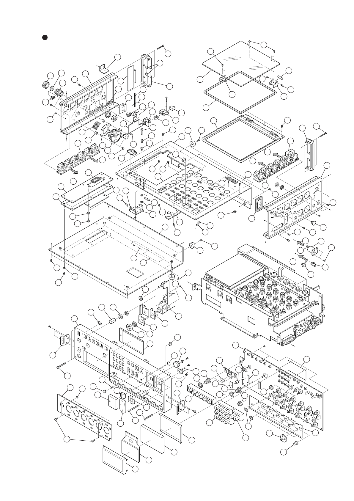
6. EXPLODED VIEW, PCB ASSEMBLY & PARTS LIST
PD-6 OVERALL EXPLODED VIEW 1 Parts List
Ref. No. Part No. Description
1 8221 3900 00 Panel, side, L, PD-6
2 8274 3750 00 PCB assy, XLR OUT, PD-6
3 8221 4290 00 Stopper, eject, battery, B, PD-6
4 8221 4070 00 Stopper, eject, battery, PD-6
5 8221 4060 00 Bracket, eject, battery, PD-6
6 8221 4081 00 Spacer, eject, battery, A
7 8226 2761 00 Knob, lock, PD-6
8 8214 4040 00 Spring, eject, PD-6
9 8204 0830 04 Screw, precision, M 2.6 x 6 BZn
10 8221 4160 00 Bracket, panel, connector, PD-6
11 8278 0170 00 Speaker, C035AS122S11
12 8277 2892 10 Cable assy, 2P, ORG, ZHR/F-WIRE/3,
13 8216 8050 00 Cushion, speaker, PD-6
14 8216 7810 00 Sheet, speaker
15 8204 1160 03 Spacer, speaker, M 2.6 x 10
16 8245 4150 00 Connector, receptacle, 10P,
17 8277 5590 07 Cable assy, 10P, 10-COLORS,
18 8277 5543 15 Cable assy, shield, 2CX3, 9P, BLK,
19 8277 5553 15 Cable assy, shield, 2CX3, 9P, RED,
20 8216 8040 00 Cushion, battery, B, PD-6
21 8260 5930 00 Cushion assy, PD-6
22 8216 8120 00 Sheet, eject, battery, PD-6
23 8221 3910 00 Panel, side, R, PD-6
24 8274 3740 00 PCB assy, XLR IN, PD-6
25 8216 7970 00 Shield, power, PD-6
26 8245 4030 02 Connector, cannon, 4P, male, HA16RA-4P
27 8277 1050 05 Cable assy, separate, 6P, L50
28 8245 4160 00 Connector, receptacle, 4P,
29 8277 5580 05 Cable assy, 4P, BLK, ZH/F-WIRE, L50
30 8207 0142 00 Cap, connector, HR10-7R-C
31 8207 0109 00 Cap
32 8216 7850 00 Packing, panel, BNC, PD-6
33 8277 5553 15 Cable assy, shield, 2CX3, 9P, RED,
34 8277 5543 15 Cable assy, shield, 2CX3, 9P, BLK,
35 8274 3730 00 PCB assy, Front, PD-6
36 8216 7821 00 Sheet, LCD, PD-6
37 8212 7070 00 Plate, reflect, LCD, PD-6
38 8216 7880 00 Spacer, reflect, LCD, PD-6
39 8221 4271 00 Guide, knob, PD-6
40 8216 7790 02 Sheet, toggle, PD-6
41 8226 2750 01 Knob, rotary, C
42 8216 7990 00 Sheet, knob, rotary, PD-6
L100
RM15TRD-10S
ZH/F-WIRE, L70
ZH/F-ZH/F, L150
ZH/F-ZH/F, L150
HR10A-7R-4S
ZH/F-ZH/F,L150
ZH/F-ZH/F, L150
Ref. No. Part No. Description
43 8226 2750 02 Knob, rotary, D
44 8260 5910 00 LCD assy, PD-6
45 8221 4020 00 Bracket, LCD, PD-6
46 8276 8710 03 Tube, UL, 5.3 x 7
47 8216 7930 00 Sheet, LED, PD-6
48 8216 5550 03 Washer, 12 x 2.5 x T2, PD-4
49 8216 7951 00 Cover, PCB, front
50 8216 7790 00 Cushion, toggle, PD-6
51 8212 7061 00 Window, LCD, PD-6
52 8226 1842 12 Button, 6 x 6 x 16.8, N3
53 8214 2700 00 Spring, 8 x 3, 0.2
54 8226 1540 00 Button, tact, PAUSE
55 8216 4080 01 Cushion, search
56 8226 1531 00 Button, REC
57 8216 6260 00 Sheet, slide, PD-4
58 8212 3260 00 Slider, REC
59 8216 3791 00 Cap, button
60 8216 7830 00 Sheet, mic, PD-6
61 8212 2682 00 Lens, LED
62 8214 4020 00 Spring, door, DV40
63 8226 2180 00 Knob, phone, PD-4
64 8260 5920 00 Button, SW assy, PD-6
65 8260 5920 00 Button, SW assy, PD-6
66 8260 5920 00 Button, SW assy, PD-6
67 8274 3710 00 PCB assy, Phones, PD-6
68 8216 3610 00 Shield, phone
69 8216 5550 03 Washer, 12 x 2.5 x T2, PD-4
70 8221 4140 00 Bracket, phones, PD-6
71 8216 5550 01 Washer, 12 x 6 x T4, PD-4
72 8216 5550 02 Washer, 15 x 10 x T4
73 8245 3400 00 Nut, phone jack
74 8216 7980 00 Sheet, front, PD-6
75 8204 0830 03 Precision, M 2.6 x 4 BZn
76 8221 3930 00 Panel, input, volume, PD-6
77 8216 7870 00 Sheet, input, volume, PD-6
78 8204 0730 02 Screw, precision, M 2 x 5 BZn
79 8226 2710 02 Knob, rotary, B
80 8226 2740 01 Knob, input
81 8226 2720 01 Button, push
82 8221 3941 00 Panel, top, A, PD-6
83 8221 3953 00 Panel, top, B, PD-6
84 8212 7080 00 Frame, cover, PD-6
85 8221 4170 00 Stopper, knob, PD-6
86 8204 2460 51 Screw, precision, TB 1.7 x 5 CZn
87 8220 8490 00 Emblem, Fostex
88 8204 0370 01 Ring, CSTW-2
89 8212 3840 01 Protector, REC, BLK
90 8216 8070 00 Tape, 5 x 5 x 0.5
91 8221 3992 00 Lock, cover, B, PD-6
92 8223 3140 00 Shaft, open, PD-6
22
Page 23
PD-6 Service Manual
PD-6 OVERALL EXPLODED VIEW 1
6
5
92
93
86
91
70
122
121
M 2 x 10 BZn
8
78
83
105
86
106
68
123
17
BBT
2.6 x 8
BZn
9
B
F 2.6 x 8 BZn
115
124
16
107
108
9
78
9
A
H
14
2
B
Cable assy (RED)
19
111
110
112
127
113
76
77
78
1
15
13
18
Cable assy (BLK)
To J1152
122
63
61
53
52
54
10
118
20
22
119
120
7
21
94
12
11
9
95
A
109
103
Nut, M4
102
104
BBT 3 x 6 BZn
126
125
D
69
Attached to
71
the jack
73
72
51
55
57
113
114
56
117
9
89
101
60
3
4
82
85
86
67
61
59
62
116
99
9
101
C
J
101
9
H
75
FBT 2.6 x 6 CZn
W 2.6 x 7.5 x 0.5
BPT 2 x 6 CZn
58
42
66
F 2.6 x 8 BZn
36
41
61
98
65
78
90
84
40
47
78
97
78
78
100
96
9
122
117
25
Attached to
the connector
9
Cable assy
F
G
Cable assy
E
128
27
23
E
F
9
G
BBT 2.6 x 8 BZn
31
75
26
9
34
Cable assy
(BLK)
33
Cable assy
(RED)
9
87
J
88
9
32
24
9
C
I
Attached to
the connector
D
29
28
30
B 3 x 6 BZn
39
42
43
35
46
79
38
48
I
74
50
64
80
49
45
44
37
81
23
Page 24
PD-6 Service Manual
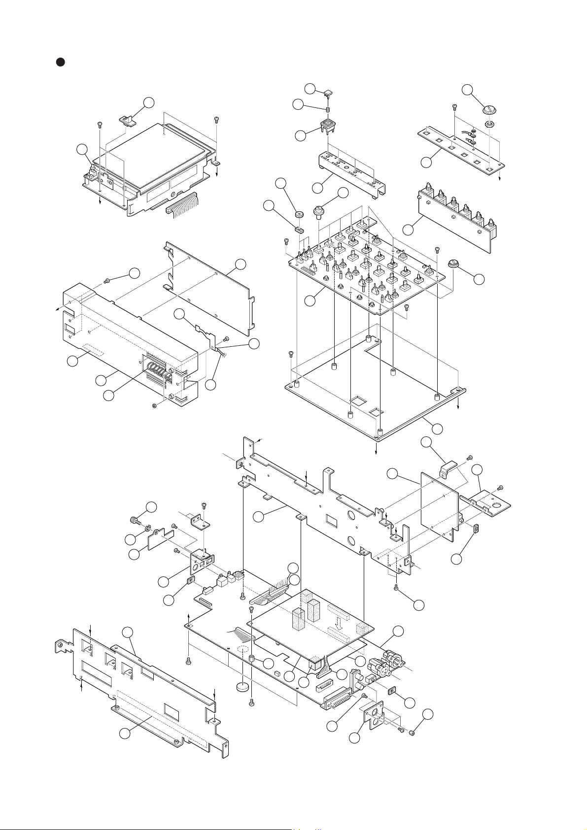
PD-6 OVERALL EXPLODED VIEW 2
B 3 x 6 BZn
40
B 3 x 6 BZn
37
38
B 3 x 6 BZn
33
Attached
to VR
39
41
D
E
Precision
2.6 x 6
36
35
B 3 x 6 BZn
46
21
29
32
28
G
3
B 2 x 3 CZn
5
B 3 x 6 BZn
31
A
30
B 3 x 6 BZn
34
B 3 x 6 BZn
6
1
4
2
N2
45
BBT 3 x 6 BZn
B 3 x 6 BZn
19
G
D
C
22
A
23
B
B
20
B 3 x 6 BZn
24
B 3 x 6 BZn
44
B 3 x 4 BZn
43
25
42
12
13
47
15
Precision
2.6 x 4
10
16
14
8
Precision
2.6 x 6
BBT 3 x 6 BZn
21
7
26
9
11
26
E
B 3 x 6 BZn
F
B 3 x 4 BZn
17
C
F
B 3 x 4 BZn
18
24
Page 25

PD-6 OVERALL EXPLODED VIEW 1 Parts List (continued)
PD-6 Service Manual
Ref. No. Part No. Description
93 8214 4033 00 Spring, cover, PD-6
94 8223 3150 00 Sleeve, open, PD-6
95 8226 2202 00 Knob, lock, PD-4
96 8221 4220 00 Bracket, shaft, cover, PD-6
97 8223 3090 00 Shaft, cover, B
98 8260 5930 00 Cushion assy
99 8212 7041 00 Cover, PD-6
100 8221 3982 00 Lock, cover, A, PD-6
101 8207 0086 01 Foot, rubber, K-15
102 8214 1030 00 Spring, brake
103 8276 9330 15 Tube, UL, SUMI TUBE, 820, F,
D5L15MM
104 8204 2250 03 Washer, RET-RING, E-1.5 ZMB
105 8216 8110 00 Cushion, drive, PD-6
106 8221 3961 00 Panel, bottom, PD-6
107 8221 4260 00 Bracket, cover, EXT, PD-6
108 8216 8000 00 Spacer, cover, EXT, PD-6
109 8221 4250 00 Cover, EXT, PD-6
110 8214 3630 00 Screw, rollet, B, M3
Ref. No. Part No. Description
111 8260 5930 00 Cushion assy, PD-6
112 8204 2440 00 PSW, 2.1 x 4 x 0.5
113 8204 0040 09 Screw, HSB, M 3 x 20 BZn
114 8204 0040 11 Screw, HSB, M 3 x 30 BZn
115 8221 3970 01 Guide, belt, L, PD-6
116 8221 3970 02 Guide, belt, R, PD-6
117 8212 7030 00 Pad, corner, PD-6
118 8221 0872 00 Cover, battery, PD-4
119 8223 3080 00 Shaft, cover, PD-6
120 8214 2911 00 Spring, cover, PD-4
121 8216 8031 00 Cushion, battery, A, PD-6
122 8216 7940 00 Cushion, EXT, PD-6
123 8223 3120 00 Cap, connector, RM15TRD-10S
124 8216 8060 00 Cushion, cap, connector, PD-6
125 N/A Label, serial number
126 8218 8200 00 Label, identification, PD-6
127 8210 0460 00 PANEL, DRESS, PD-6
128 8216 9320 10 Tube, UL, SUMI, 820, F, D4, L10
PD-6 OVERALL EXPLODED VIEW 2 Parts List
Ref. No. Part No. Description
1 8212 4942 00 Case, battery, PD-4
2 8214 3340 00 Spring, battery, PD-4
3 8214 1992 00 Spring, NP-1
4 8277 1050 15 Cable assy, separate, 6P, L150
5 8216 9320 10 Tube, UL, SUMI, 820, F, D4, L10
6 8216 6271 00 Spacer, battery, PD-4
7 8274 3770 00 PCB assy, Main, PD-6
8 8221 4240 00 Panel, BNC, PD-6
9 8204 1160 04 Spacer, M2.6 x 5
10 8204 0830 03 Precision, M 2.6 x 4 BZn
11 8221 4190 00 Panel, conn, PD-6
12 8204 0090 02 Spacer, M 3 x 8
13 8274 3780 00 PCB assy, AD/DA, PD-6
14 8216 7960 00 Shield, ADDA, PD-6
15 8216 8020 00 Cushion, PCB, main, PD-6
16 8277 5630 25 Cable assy, 10P, PH/F-8283/F, L250,
AWG26
17 8221 4100 00 Chassis, front, PD-6
18 8216 8090 00 Sheet, isolation, ADDA, PD-6
19 8221 4110 00 Chassis, rear, PD-6
20 8221 4130 00 Bracket, PCB, input, PD-6
21 8204 0830 04 Screw, precision, M 2.6 x 6 BZn
22 8274 3700 00 PCB assy, Power, PD-6
23 8221 4301 00 Heat sink, power, B, PD-6
Ref. No. Part No. Description
24 8221 4230 00 Heat sink, power, PD-6
25 8216 5370 00 Sheet, SW, PD-4
26 8216 7910 00 Sheet, SW, PD-6
27 8216 8100 00 Cushion, PCB, ADDA, PD-6
28 8274 3690 00 PCB assy, Input amp, PD-6
29 8221 4200 00 Spacer, escutcheon, PD-6
30 8274 3790 00 PCB assy, Input sel, PD-6
31 8221 4120 00 Bracket, PCB, I M, PD-6
32 8226 2710 01 Knob, rotary, A
33 8226 1461 01 Knob, rotary switch, C
34 8226 2800 01 Knob, rotary, B
35 8216 7790 01 Cushion, toggle, B, PD-6
36 8216 5550 03 Washer, 12 x 6 x T4, PD-4
37 8226 1831 08 Button, 11 x 11, N3
38 8214 2700 00 Spring, 8 x 3, 0.2
39 8226 2730 01 Escutcheon, button
40 8226 2761 00 Knob, lock, PD-6
41 8226 2720 01 Button, push
42 8277 4651 15 Cable assy, flat, 50P, P1.0, L150
43 8221 4151 00 Cover, connector, PD-6
44 8204 2250 04 Washer, RET-RING E-2 ZMB
45 8214 3630 00 Screw, rollet, B, M3
46 8221 4180 00 Cover, case, PD-6
47 8216 8250 00 Cushion, core, PD-6
25
Page 26

PD-6 Service Manual
PD-6 OVERALL EXPLODED VIEW 3 Parts List
Ref. No. Part No. Description
1 8221 4310 00 Plate, cover, lock, PD-6
2 8221 4000 00 Bracket, cover, PD-6
3 8204 2450 42 Screw, precision, M 1.7 x 4 BZn
4 8212 7051 00 Window, drive, PD-6
5 8221 4051 00 Bracket, drive, rear, PD-6
6 8204 2460 51 Screw, precision, TB 1.7 x 5 CZn
7 8270 9180 00 DVD-RAM drive assy, PC-2
8 8223 3100 03 Spacer, 5
9 8223 3100 02 Spacer, 4.5
10 8223 3100 01 Spacer, 3.5
11 8221 4041 00 Bracket, drive, front, PD-6
12 8223 3110 00 Shaft, bar, eject, PD-6
13 8221 4030 00 Bar, eject, PD-6
14 8204 2260 00 PSW, 3.1 x 5.4 x 0.13
Ref. No. Part No. Description
15 8204 2250 04 Washer, RET-RING E-2 ZMB
16 8204 0730 02 Screw, precision, M 2 x 5 BZn
17 8274 3900 00 PCB assy, SW-DISC-UNLOCK
18 8277 5660 00 Cable assy, FPC, 70P,
5602/P-5602/P, PD-6
19 8216 8010 00 Cushion, FPC, PD-6
20 8221 4210 00 Bracket, PCB, drive, PD-6
21 8274 3720 00 PCB assy, Drive, PD-6
22 8221 4280 00 Bracket, FPC, PD-6
23 8218 8130 00 Label, laser, caution, PD-6
24 8218 7060 00 Label, push, PD-4
25 8277 5710 06 Cable assy, earth lug, D3-D2,
#22, L60
26 8204 0090 03 Spacer, M3 X 10
PD-6 CABLE ASSY & CONNECTION
Ref. No. Part No. Description Connection
W001 8277 0912 25 Cable assy, 6P, ORG, ZH/F-ZH/F, L250 MAIN J704 <-> PHONES J704
W002 8277 0941 22 Cable assy, 9P, RED, ZH/F-ZH/F, L220 MAIN J902 <-> POWER J805
W003 8277 1050 05 Cable assy, separate, 6P, 50mm DC IN connector <-> POWER J804
W004 8277 1050 15 Cable assy, separate, 6P, 150mm NP-1 Battery section <-> J803
W005 8277 5504 15 Cable assy, SHIELD1CX4, 8P, BLK, ZH/F-ZH/F, L150 INPUT AMP J4 <-> FRONT J1
W006 8277 5514 25 Cable assy, SHIELD1CX4, 8P, RED, ZH/F-ZH/F, L250 MAIN J703 <-> FRONT J3
W007 8277 5503 15 Cable assy, SHIELD1CX3, 6P, BLK, ZH/F-ZH/F, L150 INPUT AMP J5 <-> FRONT J2
W008 8277 5503 10 Cable assy, SHIELD1CX3, 6P, BLK, ZH/F-ZH/F, L100 ADDA2 J2 <-> MAIN J705
W009 8277 5513 10 Cable assy, SHIELD1CX3, 6P, RED, ZH/F-ZH/F, L100 ADDA2 J3 <-> MAIN J706
W010 8277 5502 25 Cable assy, SHIELD1CX2, 4P, BLK, ZH/F-ZH/F, L250 ADDA2 J101 <-> FRONT J101
W011 8277 5512 15 Cable assy, SHIELD1CX2, 4P, RED, ZH/F-ZH/F, L150 ADDA2 J301 <-> FRONT J301
W012 8277 5522 10 Cable assy, SHIELD1CX2, 4P, ORG, ZH/F-ZH/F, L100 ADDA2 J501 <-> FRONT J501
W013 8277 5543 15 Cable assy, SHIELD2CX3, 9P, BLK, ZH/F-ZH/F, L150 XLR OUT J709 <-> ADDA2 J4
W014 8277 5543 15 Cable assy, SHIELD2CX3, 9P, BLK, ZH/F-ZH/F, L150 XLR IN J707 <-> INPUT SEL J701
W015 8277 5553 15 Cable assy, SHIELD2CX3, 9P, RED, ZH/F-ZH/F, L150 XLR OUT J710 <-> ADDA2 J5
W016 8277 5553 15 Cable assy, SHIELD2CX3, 9P, RED, ZH/F-ZH/F, L150 XLR IN J708 <-> INPUT SEL J702
W017 8277 5563 10 Cable assy, SHIELD2CX3, 9P, ORG, ZH/F-ZH/F, L100 MAIN J701 <-> PHONES J703
W018 8277 4651 15 Cable assy, FLAT, 50P, P1.0, L150, CORE DRIVE J902 <-> MAIN J1151
W019 8277 5640 10 Cable assy, FLAT, 20P, P1.0, L100 INPUT AMP J2 <-> FRONT J6
W020 8277 5650 15 Cable assy, FLAT, 34P, P1.0, L150 FRONT J4 <-> MAIN J4
W021 8277 5580 05 Cable assy, 4P, BLK, ZH/F-WIRE, L50 POWER J801 <-> DC OUT connector
W022 8277 5580 05 Cable assy, 4P, BLK, ZH/F-WIRE, L50 POWER J802 <-> DC OUT connector
W023 8277 5590 07 Cable assy, 10P, 10-COLORS, ZH/F-WIRE, L70 AUX I/O connector <-> MAIN J801
W027 8277 5611 25 Cable assy, 11P, PH/F-PH/F, L250, AWG24 MAIN J901 <-> POWER J806
W028 8277 5630 25 Cable assy, 10P, PH/F-8283/F, L250, AWG26 MAIN J908 <-> INPUT AMP J9
W029 8277 2892 10 Cable assy, 2P, ORG, ZHR/F-WIRE/3, L100 Monitor speaker <-> MAIN J702
W030 8277 0870 20 Cable assy, 2P, BLK, ZH/F-ZH/F, L200 SW UNLOCK J801 <-> INPUT AMP J3
W031 8277 5602 30 Cable assy, 2P, PH/F-PH/F, L300, AWG24 POWER J807 <-> DRIVE J903
W032 8277 5710 06 Cable assy, EARTHLUG, D3-D2, #22, L60 DVD-RAM drive <-> Chassis
W033 8277 5720 06 Cable assy, EARTHLUG, D3-D2, DUBLE, #22, L60 DVD-RAM drive <-> Chassis
26
Page 27

PD-6 OVERALL EXPLODED VIEW 3
PD-6 Service Manual
17
B 3 x 6 BZn
24
3
3
4
2
23
1
8
6
3
10
9
9
5
6
25
7
14
13
15
26
12
16
25
11
3
12
20
21
6
18
19
22
16
27
Page 28

PD-6 Service Manual
PD-6 PCB ASSEMBLIES
• Parts Side of ADDA PCB
C5
C6
+
D103
D104
D105
D101
D204
D203
D8
D205
D201
D303
D304
D305
D404
D403
D12
D405
D503 D504 D505
D603
D16
D604
D605
C4
Q2
+
C2
L3
+
+
+
C3
1
1
Q1
+
C1
U6U7 U8
U5
2919
2010
J1 30
MAIN
91
2
W1
U1
C7
15
U3
C12
1
L1L2
Q102
D106
C125
C132
C101
R137
C112
U108
K101
C105
C111
R111
C116
+
U105
R112
C128
C134
+
U101
C102
+
C126
U102
R108
R110
+
D7
Q101
C129
R129
R126 R226
C131
R131
R114
C114
R113
C107
C130
+
C103
1
+
C104
C124R148
1
C138
+
C137
C139
C127
C109
C136
R109
C110
C118 C119
U104
R142
R141
15
C121
R118
C10
+
C151
C152
R156
U4
C17
+
+
C14
C163
C13
+
C122
5
C168
R151
R155
R152
Q152
R173
R153
C155
R170
C154
C162
C161
C158
R168
U151
12
R154
C153
U152
+
+
R164 R264
Q202
C212
D206
+
U109
C232
U205
R212
U208
+
4
5
J101
BLACK RED ORANGE
U206
C204
C224 R348
D202
D102
U106
C239
C238
C202
C227
C205
U202
C236
R107
R209
R210
R211
+
C117
1
W102
W103
C123
C120
C169
U153
Q252
1
R270
C255
U251U252
1
K151
D151
C263
C164
+
+
+
C228
U201
C234
C231
C230
C254
C229
R214
C210
C258
C261
R213
C203
C237
C262
R273
R268
C207
R248
R253
C201
R208
R255
R231
C214
R229
Q201
C225
C226
C208
+
U209
R237
R204R205
C301
R337
C211
C312
+
C332
U308
C311
C305
R311
C316
R342
Q302
D306
R310
R312
C326
R308
U305
U302
+
+
C325
C302
+
C328
C331
C334
C330
R314
R313
C303
C338
C310
U304
C412
C329
U309
C432
R329
R326 R426 R526
R331
C314
C307
U408
1
U301
U406
C304
C324
C339
C337
C336
R309
C318 C319
D402
D302
U306
+
C438
C327
C309
C405
R307
R411
+
1
R341
15
C321
R318
R251
C251
C252
1
C253
C264
+
R252
C352
R256
R254
C363
C351
R356
R351
R352
R353
R354
C353
C354
C362
U352
+
+
R364
R355
C361
+
C358
C322
Q352
R368
R373
C355
C368
U351
12
R370
5
K351
+
C320
D351
C364
U353
C463
+
+
C424
1
+
D406
R412
4
J301
R410
C323
R470
R409
1
U405
C439
C427
U402
C436
C369
U451U452
R464
+
5
C404
C402
C317
W302
W303
Q452
C455
C428
U401
C431
C434
C430
C410
R414
C403
C458
C462
C429
R413
C437
R473
C454
C461
R468
Q402
C407
C401
R448
R408
R453
R455
C512
+
U409
C532
R429
R431
C414
C425
U508
C501
R537
R437
C511
C411
C505
+
R511
R404R405
C426
C408
C516
R542
R541
R518
R451
R452
C451
C551
C552
C452
R556
R456
1
C453
R454
C464
R554
C563
+
+
D506
U505
R512
C528
C531
C534
R514
C530
+
C525
R548
C538
C502
+
C526
U502
R508 R509
R510
+
C510
15
C521
R551
R555
R552
R553
C553
C554
C562
U552
+
R564
R513
C503
U504
C558
C561
C504
+
C522
Q502
C529
C507
C536
Q552
R568
U509
R529
R531
C514
1
U501
C524
D502
C539
+
C537
C527
C509
R507
C518 C519
C520
5
C568
R573
C555
R570
U551
12
K551
+
FRONTFRONTFRONT
U606
D551
C564
U553
C612
C632
U608
C605
1
R611
C663
Q602
D606
+
C629
R613
U601
C637C638
R626
C607
R648
C636
C601
R608
R631
C614
C626
R629
U609
C625
R637
C611
+
R604
4
3
MAIN
+
D602
U506
C624
U605
R612
C628
C631
C634
R614
C630
+
C603
4
5
J501
C604
C639
+
C602
C627
U602
R610
C610
R609
C517
W502
W503
C523
C569
R673
R651
R653
R655
Q652
1
R670
C655
U651
1
U652
+
R664
+
C658
C654
C662
C661
R668
R652
C651
C652
R656
R654
1
C653
C664
+
28
C16
R265
Q151
R169
R165
D153
BLACK
C165
C166
C15
+
+
XLR OUT
Q251
R269
C266
16
MAIN
1
Q351 Q451
C366
R369
C265
J2
9
J4
R365
C365
D353
8251724100
R465
R469
C466
PCB,ADDA2,PD-6
C465
MAIN
J5
C566
Q551
R569
1
J3
1
R565
6
C666
C565
RED
9
XLR OUT
D553
R665
R669
Q651
C665
Page 29

• Foil Side of ADDA PCB
PD-6 Service Manual
R628
R622
U607
R619
R623
R634
R624
R632
R633
R630
C613
R640
R603
C633
R602
R601
R639
8
51
C608
R605
24
31
R625
R620
U603
R647
K601
R606
R621
R615
R646
R616
R645
R638
C606
R643
R627
C615
R607
R617
R644
R635
D17
R636
12
C609
J501
D14
R523
R534
14
R536
1
12
J7
R522
C513
R535
R532
R530
C515
U507
R519
R524
R533
U503
R547
R501
R520
R525
R521
D15
U510U610
K501
R506
R528
R515
R546
R516
R538
R545
R527
R503
R505
C506
R543
R539
R428
R422
U407
R438
R419
R517
R502
R423
R434
R544
C533
R540
R402
5
C433
R425
R416
R424
R415
R421
R432
R433
R420
R445
R446
C406
R430
C413
R443
U403
R447
R403
R440
R427
R444
C415
R435
R401
U410
R439
8
K401
8
51
R504
C508
R406
R407
D13
R323
R417
41
J301
R436
D10
12
C409
R334
R122
R322
R328
U307
R338
R336
1
C313
R335
R332
R330
C315
R319
R324
R333
U303
R347
R301
R320
R325
R321
D11
U310
R315
R346
R316
R345
R327
R303
C306
R343
R339
R317
R302
C333
R340
R344
R223
R202
R234
C233
K301
R306
R305
8
R304
C308
12
R228
U207
R222
R219
R224
R232
R233
R230
C213
R240
R247
R203
R201
R239
8
R220
R225
U203
R221
R215
R246
U210
R216
R245
R238
C206
R243
R227
C215
R217
R244
R235
R236
D9
R123
R134
4
J101
D5
125
K201
51
C209
R206
R207
R128
U107
R138
R119
R125
R117
R116
R124
R115
R132
R133
R120
R121
R145
R146
C106
R130
R127
R143
U103
C113
R147
R103
D6
1
R135
C115
R139
R101
R136
U110
1
K101
12 8
R105
R106
R102
R104
C108
R1
R2
D1
D2
D3
C18
R3
R5
R144
C133
R140
5
D4
C19
R4
R6
R7
R8
32
31
J1
1
2
R661
R674
R672
R659
R657
R675
C667
D552
R658
K551
R558
8
51
R671
12
R676
R667
R663
C660
R662
R666
R561
R574
R572
R575
C567
R567R571
R562
R559
R557
R563
R566
R576
16
R257R259
R275
R267
D152
8
51
R258
K151
R158
R171
R263R271
C260
R262
R266
R161
R174
R172
R175
C167
R167
12
R276
J2
19
J4
R162
R159
R157
R163
R166
R176
C160
D352
R459
R457
K351
R358
R359
R357
8
5
R458
R471
1
12
R476
R472R474
C467
R467
R475
R462
R463 R466
C460
R361
C367
R372R374
C560
R461
J3
R375
R367R371
R362
R363
R366
R376
C360
R261
C267
R272R274
61
19
J5
29
Page 30

PD-6 Service Manual
• Parts Side of INPUT AMP PCB
REC TR
2+4
5+1
1
3C
6
5
S19
4
10
2
FS
88.2
1563C
10
1
10
1
44.1/16
DIGITAL
29.97
96
3C
DF
3C
48
S1
44.1
48/16
CLOCK
S2
INT
EXT
FRAME
DF 30
5
MAIN
6
10 1
56
+
C4
+
C5
56
J9
C1
1423
C2
+
+
J1
C101
C102
+
C103
C109
C104
+
R121 R221
J6
S204
62
1
5
C201
+
C110
R112
C202
+
C204
+
C209
+
C203
R212
C210
+
C309
C302
+
C303
C304
R321
C301
+
J7
S404
62
1
5
C401
R312
C310
C402
+
+
C404
C409
R421
C403
C502
+
+
C503
C410
C509
R412
C504
+
R521
J8
62
1
5
C501
C601
+
C510
C602
R512
+
+
C604
C609
R621
S604
+
C603
C610
GAINHPF
INPUT
R612
25
S4
24
23.976
10
TC GEN
1
24H
S3
REC
FREE
EXT
BWF
OPT
S6
REPRO GEN
S5
-0.1% +0.1%NORM
S7 S8
56103C
AUDIO
FILE
TC
OUT
PULL
UP/DOWN
2
J2
+
C117
OFF
-12 -6 -12 -12 -12 -12 -12-6 -6 -6 -6 -6OFF OFF OFF OFF OFF
S103 S203
W1
S9 S10
C3
ON OFF ON ONOFF OFF OFF OFFOFF ONONON
+
DISK
J3
1
UNLOCK
PANEL
OFFLOCK
191
• Parts Side of DRIVE PCB
ANA
4.75V
15
U902
C902
MECH
W903
+
L902
R903R904
15
U901
C907
C901
1
C621
S603
S18
D11
S13
L904
+
+
LIMITER
+
C421
+
C517
D12
S14
PLAY STOPFRONT
PCB,INPUT AMP,PD-6
+
R909R910
4.75V4.75V
S15
DIG
W902
L901
+
C221
+
C317
D14
R905R906
+
C121
+
C217
K1
1
12
D17
D13
20
REWIND F FWD
+
R901
+
C321
+
C417
S303 S403 S503
S11 S12
D18
S16
K2
1
12
8252515101
L903 L905
+
+
C521
+
C617
S17
K3
1
12
D19
3.15V2.45V
R907
C909
R902
15
U903
C906
C903
C908
15
U905
C905
W901 W904
15
C910
U904
C904
C912
R908
+
502
1
49
30
J903
DRIVE
DRIVE
J901
69 55 35 15 1
70 50 30 10 2
8252516204
PCB,DRIVE,PD-6
J902
MAIN
D901
J904
POWER
12
Page 31

• Foil Side of INPUT AMP PCB
PD-6 Service Manual
3C
56
D7
1
62
654
5
321
R604
R603
R627
R628
D601
C608
C622
4
C605
R614
C613
C611
R619
R616
C612
1
R625
R620
R602
D602
C623
R514
R615
1
C606
C607
1
R613
R618
R617
U602
C614
R622
R624
R629
R630
R631
R632
214563
123
C618C619
456
5
R503
R504
1
R501
R601
D501
R528
C508
C522
4
C505
R519
R516
C512
1
C624
R525
8
R502
D502
D401
R527
C523
C422
R414
R515
1
C506
C507
1
C511C513
R518
R517
U502
C514
R531
R532
214563
123
456
R520
4
C405
C413
R419
R513
C412
1
R522
R524
R529
C524
R530
R425
C518C519
16
1
123123
12
R403
R428
C408
U401
R416
J5
62
654
321
R404
R427
C423
1
C406
C407
1
C411
R417
R418
U402
C414
R424
R431
R432
214563
123
R420
5
R203
R228
C211
R216
2
3
546
R220
J4
62
654
5
321
R204
R227
D202
C223
1
C206
C207
1
R217
R218
U202
C214
R224
R231
R232
24563
1
1
5
1
1
R101
R201
D101
R202
R128
C122
R114
R215
4
C105
R119
R213
C112
R222
R229
R230
C224
R125
C218C219
8
12
R303
R304
1
5
R301
R401
D301
D402
R328
C308
C322
R314R402
R415
4
C305
C313
R319
R413
C312
1
R422
R429
R430
C424
R325
C418C419
8
1
12
R302
D302
D201
R327
C323
U301
1
C306
C307
1
R317
R318
R316
U302
C314
R324
R331
R332
1
24563
23
1
456456
R320
8
123123
C208
C222
R315
R214
4
C205
C213
R219
R313
C212
1
R322
R329
R330
C324
R225
C318C319
1
BLACKBLACK
C108
U101U201
R116
1
123123
42
R103
R104
3
D102
R127
1
C106
C107
1
C111C113C311
R117
R118
U102
C114
R131
R132
145632
231
456
R120
56
1
R102
10
56
C123
R115
R113
R122
R124
R129
R130
C118C119
56
C124
56
D5
U1
3C
3C
D4
3C
D6
3C
123
10
1
10 1
101
10
1
101
D10
• Foil Side of DRIVE PCB
W905
21
J904
R911
1
D9
D15
D16
D8
123
D2
123
D1
D3
123
20 10 2
1919
J903
1
C913
C914
R912
31
Page 32

PD-6 Service Manual
C151
C152
C153
C154
C251
C252
C253
C254
C351
C352
C353
C354
J701
1
9
13
4
J703
2
J704
1
2
5
6
J705
1
2
5
6
R151
R152
R156
R157
R158
R160
R161
R251
R252
R256
R257
R258
R259
R260
R261
R351
R352
R356
R357
R358
R359
R360
R361
R452
R459
1511
16 20
S101
10
5
6
1
1511
16 20
S201
10
5
6
1
1511
10
16 20
S301
5
6
1
C702
W701
R159
C451
C452
C453
C454
C551
C552
C553
C554
C651
C652
J702
1
9
J706
1
2
5
6
R451
R456
R457
R458
R460
R461
R551
R552
R556
R557
R558
R559
R560
R561
R651
R652
R659
1511
16 20
S401
10
5
6
1
1511
16 20
S501
5
10
6
1
C653
C654
R656
R657
R658
R660
R661
1511
16 20
S601
5
10
6
1
21
S4
GH
J501
C3
21
S4
GH
J601
3C
J708
91
L501
L502
L601
L602
21
S4
GH
J301
3C
21
S4
GH
J401
3C
L301
L302
L401
L402
21
S4
GH
J101
C3
21
S4
GH
J201
3C
J707
19
L101
L102
L201
L202
• Parts & Foil Side of INPUT SEL PCB
1
+
L701
S101
20
15
10
5
12431
19
XLR IN
J701
C701
16
20
R153R154 R155
11
15
10
R162
6
1
6
2
5
INAMP INAMP INAMPINAMP PCB,INPUT SEL,PD-6
BLACK
S201
16
11
6
5
1
8252515104
R253R254 R255
R262
20
15
10
5
+
16
11
6
1
2
R353R354 R355
R362
165
C703
S401
20
15
10
5
U701
32/S1/M 4 5 6
S301
19
J702
XLR IN
RED
L702
S501
16
20
R453R454 R455
11
15
10
R462
6
1
5
16
11
6
1
2
165
+
R553R554 R555
R562
C704
20
15
10
5
S601
16
R653R654 R655
11
R662
6
1
• Parts & Foil Side of PHONES PCB
19
J703
ORANGE TO MAIN
J702
R702
16
TO MAIN
J704
ORANGE
PCB,PHONE,PD-6
8252515103
• Parts & Foil Side of XLR IN PCB
J101
J707
to INPUT SEL
J201
J301
1
9
S701
OFF
8252516002
POWER
ON
PCB,XLR IN,PD-6
31
6524
J401
J708
to INPUT SEL
J501
J703
J704
16
19
78
W701
654
123
W702
L701 L702
32
7645
1
J601
1
9
REDBLACK
32
Page 33

• Parts Side of MAIN PCB
8251721400
U721
R858
R859
C755
R856
+
C757
R755
R756
R759
R766
U716
W701
C819
C820
C821
C822
1
5
U723
W706
W707
W708
R863
C703 C705
+
C722
+
C723
+
C724
+
C741
+
C742
+
C743
C744
C745
C746
C750
C760
+
C761
J702
2
1
R765
R771
R772
R773
R784
R785
R786
1
8
U702
1
8
U703
1
9
U711
1
9
U712
W702
W703
W704
W705
C701
C706
+
C719
+
C720
+
C721
+
C738
+
C739
+
C740
C747C749
+
C751
C762
C772
+
C773
+
C774
+
C777
+
C794
C795
C798 C800
+
C803
+
C809
L801
L809
Q705
R781
R782
R783
R815
R816
R817
R818R821
R822
R824
R825
R828
R830
R831 R832
R833
R834
1
8
U701
1
8
U704
1
5
U706
1
9
U710
1
9
U713
U714
C79
R66
R67
R862
L702
C702 C704
C733
C734
+
C736
+
C737
+
C766
C771
1
8
U14
1
8
U707
U717U718U719U720
+
C824
52 13
64
78
+
C825
+
C826
4
1
J1154
L701
C763
+
C770
C779 C780
C781 C782
C786C787
C789
C796C797
C799
C806
C937
C938
C939
C940
C941
C942
C1157
+
C1172
J1152
L910
L916
Q706
R800 R801
R803
R804
R806
R807R811
R819
R820
R826
R827R829
R835
R836
R837
R838
R839
R840
R842R843
R932
R1189
R1190
51
610
C804
C805
C807C808
C1161
+
C1165
+
C1166
D703
R823
R841
1
8
U705
80100
36
20
1
40
72
U1152
108
R931
R933
R934
U908
1
2
3
4
C930
+
C932
C1154
C1155
C1160
C1164
C1181
C1182
D903 D904
D905
43
21
R928
R1177
R1181
R1182
R1183
R1184
R1185 R1187
15
U904
U907
C1156
C1162
E1151
E1152
R1152
R1153
R1154
R1156
R1157
R1158
R1188
W1151
X1004
W1153
R1192
2
34
1
X5
C3
+
C5
C10
C12
C17
C23
C26
C27
C33
C35
C62
C64
C66
C71
+
C85
+
C90
R65
U41
R68
R69
C83
C84
C92
C94
C97
R64
R70
C1151
C1152
C1163
19
J902
R3
R4
R5
R9
R10
R11
R19
R20
R47
R48
R49
R50
R51
R58
R59
R1155
R1175
R1176
1
60
61
240
120
181
U6
1
8
U12
1
13
U13
1
13
U18
1
8
U1154
W1
W2
W1152
X2
J5
1
2
C7
C9
C18
C87
C89
D4
D5
D6
D7
D8
1
9
U1151
C15
C29
C42
C44
C52
1
23
4
X1
R6R7R12
R13
R17
R18
1
11
U19
B1
C78C11
C14
+
C19
C20
+
C21
+
C22
C24
C25
C28
+
C31
C36
C38
C40
C49
C50
C51
C53
C74
C75
C76
C82
C96
U37U38
1
11
U24
1
11
U27
1
11
U35
E5
D1
D2
E3
E4
14
178
/RESET
TDO
TMS
TDI
/ASEBRK
/TRST
TCK
J2
R2
R8
R21
R22
R23
R25
R33
R37
R39
U21
U25
U28
1
U29
X3
+
C13
15
U5
C34
C43
C48
C54
C57
1
8
U40
J1
12
R34
U7
1
28
U10
1
8
U16
C1
C2
1
24
3
C181
C182
C183
C184
C185 C187
C188
C191
C195
C196
C197
D10
C285 C287
C288
C291
+
C381
C382
C384
C385 C387
C388
C391
C395
C397
+
C1002
C1007
C1008
C1011
D3
E1
E281
E381
E1001
L1003
L1004
R1
R14
R16
R41
R181
R182 R183
R184
R185
R186
R187
R189R190
R191
R281
R282 R283
R284
R285
R286
R381
R382 R383
R384
R385
R386
R387
R389R390
R391
R1002
R1004
R1005
R1007
R1008
R1075
U2
1
U3
1
9
U9
U26
1
10
20
30
50
60
80
100
U181
1
10
20
30
50
60
80
U381
10
20
50
60
100
80
30
U1002
1
1
9
U1004
1
8
U1005
C396
+
C1005
C1019
C1041 C1044
C1046
+
C1049
C1053
L181
L281
L381
L1001
R188 R288
R388
R1001R1003
R1019 R1020
R1022
R1023
1
8
U1
6
2
1
3
X1001
C59
C60
+
C63
C65
C67
C68
+
C73
W901
W902
+
C186
C929
+
C931
C1004
C1006
C1009
C1016
C1017
C1018
C1021
C1022
C1030
C1048
+
C1054
C1060
C1123
E1002
E1005
E1006
L1005
L1006
L1007
R1006
R1010
R1012
R1024
R1027
R1034
R1037
1
11
U20
1
9
U30
20
40
50
90
80
100
30
70
U1008
1
U1009
U1010
U1011
1
U1019
1
U1032
1
X1002
C93
C1024
C1025
C1026
C1029
C1032
+
C1034
C1035
C1042
C1045
C1051
C1052
C1064 C1066
C1068
C1075
C1082
C1086
+
C1095
+
C1109
D1001
D1002
D1003
E1003
E1004
L1011
L1012
L1013
R1009
R1011
R1028
R1031R1032
R1033
R1035
R1036
R1046
R1059
R1060
1
13
U15
U1012
U1015
U1016
U1017
1
8
U1020
1
33
20
19
32
51
52
64
U1024
C1124
1
U1034
C1079
+
C1088
C1089
C1091
C1094
C1098
C1099
C1102
C1103
C1107
C1108
C1110
C1112
+
C1113
+
C1114
+
C1115
+
C1116
C1117
C1118
D1004
D1005
D1007
D1008
D1009D1010D1011
1S4G
2H
3C
L1014
L1015
L1016
L1017
R1038
R1039
R1040
R1043
R1047
R1054
R1055
R1061
R1063
R1064
R1067
R1068
R1069
R1071
R1072
R1073
R1074
13
1
U1007
1
8
U1026
1
8
U1028
1
5
U1029
1
U1030
5
1
U1031
+
C1090
G
C
H
1
5
6
4
3
2
R1052
R1062
R1076
R1077
R1078
+
C948
+
C947
+
C950
+
C951
+
C952
1
Q903
1
Q904
R943 R944
C189
+
C286
R946
R948
+
C386
C389
+
C903
C904
C905
C908
C909
C911
C914
C915
C917
C918
C923
C924
C925
C926
+
C935
+
C936
+
C949
+
C1028
11
J901
1
C1055
C1056
+
C1071
C1119
C1120
D906 D909D910D912 D915D916
D1006
L1008
L1018
L1019
1
Q901
1
Q902
R903
R904
R905
R910
R911
R912
R913
R918
R921
R1048
R1065
R1066
R1070
1
U182
1
U282
1
U382
1
9
U902
15
U903
D918 D919
W903
W904
C289
R947
R922
R924
C1159
C41
49
502
1
J3
C37
C39
C47
POWER
EXT ROM
POWER
RED
PCB,MAIN,PD-6
JTAG
EXT DRIVE
USB
(FIRE-USB1 LOAD)
D-
DGND
D+
~
~
PD-6 Service Manual
33
Page 34

PD-6 Service Manual
WORD I/O
VIDEO IN
INAMP
C945
+
110
J908
R945
C901
+
C902
C907
C910
C916
C921
C922
C927
C928
C944
+
D901D902
D907 D908D911
D913 D914D917
J905
64
3
215
J1003
R901
R902
R909
R914
R915
R919
R920
R923
R927
R941
R942
1
9
U901
C906
C919
C920
R907
C912
R906
C913
R908
TC IN
75
C1061
C1069
+
C1070
C1073
C1074
+
C1076
C1077
+
C1078
C1080
+
C1084
+
C1097
C1100
C1101
+
C1104
C1105
C1106
+
C1111
+
C1121
C1122
E1004
J1002
15
J1004
L1010
L1020
L1021
L1023
L1024
L1025
L1026
R1029
R1030
R1044
R1045
R1049
R1050
R1051
R1053
R1056
R1057
R1058
S1001
1
10
20
40
50
70
90
100
30
80
U1014
U1018
1
1
U1021
1
U1023
1
5
U1027
1
8
U1033
GND
OUT
VIN1
VCC
2
4
3
C1063
C1072
AATON
C1081
C1083
C1085
+
C1092
+
C1093
+
C1096
+
R1041
R1042
111
2212
3323
34
44
U1025
J1001
E1003
R1021
TC OUT
+
C1023
C1062
C1067
E1005
E1006
C1015
C1027
+
C1031
C1037C1038
C1039
C1040
C1043
C1047
+
C1050
C1057
C1058
+
C1059
C1065
E1002
L1009
R1013
R1014
R1015
R1016
R1017
R1018
R1025
R1026
1
U1006
1
9
U1013
C1036
5
U1022
1
C295
C1010
+
C1012
E181
R287
1
10
20
30
80 60
50
100
U281
1
9
U1003
C6
C69
J6
32
31
1
2
W905
C1003
C1020
+
R35
R36
R60
R62
25
1
U8
1
28
U11
1
8
U34
ADDA
R61
C55
C56
C58
R38
ADDA
1
2
4
3
J7
C199
+
C299
+
C399
+
C1033
+
C190
+
C192
C194
C282
C283
C284
C290
+
C293
C294
C296
C383
C390
+
C392
C393
C394
C1013
C1014
E281
E381
E1001
L182
L282
L382
L1002
R289 R290
R291
1
9
U183
1
9
U283
1
9
U383
C193
C292
C91
1
9
U39
C281
+
C297
E1
R42
R43
R44
C4
C8
C30
C32
+
C45
C61
C70
C80
C81
1
8
U4
C77
R15
R24
1
8
U23
1
8
U32
E2
J704
16
+
C16
+
C46
C86 C88
C95
C1153
R52
R53
R1151
R1159 R1160 R1161 R1162
R1163
1
13
U17
1
11
U22
D9
1
11
U1155
2
1
PHONES
ORANGE
116
49
32
64
U1153
17
1
U1156
R1199
41
J1154
R1198
R1200 R1201
U1157
C1167
C1168
C1169
C1170
C1171
C1173
C1176
C1177
C1178
C1180
C1183
E1151
E1152
49
502
1
J1151
21
22
1
220
19
40
39
R1164
R1165
R1166
R1167
R1168
R1169
R1170
R1178
R1179
R1180
R1191
X1003
DRIVE
J705
61
34
33
1
2
J4
R860
R861
U725
C707
C713
C725C726
C727
C735
C748
C754
C756
+
C764
+
C765
C767
C768
C769
C775
C776
C778
C783
+
C784
C785
C788
+
C790
C792
+
C793
+
D704
Q701
Q702
R701
R702
R713R719
R725
R726
R727
R728
R729
R730
R731
R732
R744 R745R746
R747
R748
R753
R754
R757
R760
R761
R762
R764
R768
R770
R774
R775
R776
R777
R778
R779
R780
R787
R788
R791
R792
R793
R794
R795
R796
R797
R798R799
R802
R805
R808
R809
R810R812
R813
R814
U708
U722
C823
U910
C810
C811
C812
C813
C814
R844 R845
R846R847
R848
R849
R850
R851
R857
ADDA
ORANGE
ADDA
FRONT
RED
BLACK
J706
61
C709
C710
C711
C715
C716
C717
C729
C730
C731
R705
R706
R707
R708
R709
R710
R715
R716
R717
R721
R722
R723
R736
R737
R738
R739
R740
R741
R749
R750
R751
C815
C816
C817
R852
R853
R854
C708
C714
C728
R703
R704
R714R720
R733
R734
R735
C712
C718
C732
R711
R712
R718R724 R742
R743
R752
C818
R855
+
C758
D701
D702
J701
1
9
J703
1
8
1
Q704
U709
U715
FRONT
PHONES
RED
1
C752
C753
+
C759
J801110
R758
R763
R767
R769
R789
R790
8P
J904
+
C791
+
C801
+
C802
R929
R935
R936
R937
R938
R939
R940
U906
L1101 L1102
C1158
C1174
C1175
R930
S701
AUX
I/O
REMOTE
+4-60 -10
AUX
ATT
J1153
C1179
J903
L906
L908
R916
R917
R925
R926
R1186
USB
IEEE1394
C72
R45
R46
R54
R55
R63
E3
E4
2
1
14
7
14
TDO
TMS
/ASEBRK
TDI
/TRST
TCK
/RESET
DGND 8
1
R26
R27
R28
R29
R30
R31
R32
R40
R56 R57
8
U36
1
1
8
U33
• Foil Side of MAIN PCB
34
Page 35

8252516201
D17
GR
D18
D21
D23
D24
R47
R48
R49 R50
R51
R52
R53
R54
S1
S4
S5
10
65
1
3C
+
C5
C13
+
C19
+
C20
+
C27
+
C29
C43
C45
+
C48
D53
J5
2
20
19
1
1
12
K1
Q4 Q5 Q6 Q7 Q8
R3
R37 R38
R39
R40
R41
S2 S3 S6 S7 S8 S9
S10
2B3C1A
S30
10
65
1
3C
5
1U2
U8
1
8
1
11
U9
1
9
U10
1
9
U11
1
5
U16
+
C14
C25
+
C28
+
C30
C31
C32
C44
C46
+
C106
+
C107
GR
D101
GR
D201
R101
S11
S12
S13
S15
S16
S17
S18
S20
S21
S22
S23
S31
S101
S103
1
5
U1
5
1
U4
C51
C52
C12
C26
C101
+
C104
+
C105
+
C206
+
C207
S102
S201
1
U101
5
+
C2
C6
C7
+
C8
+
C9
+
C34
+
C38
C102
C301
+
C304
+
C305
+
C306
+
C307
+
C406
+
C407
C501
C502
+
C504
+
C505
+
C506
+
C507
+
C607
D19 D20
GR
D301
GR
D401
GR
D501
GR
D601
R201 R301 R401 R501
S14 S19
S24 S25
S26 S27
S28
S51
S202
S203
S301
S302
S303
S401
S402
S403
S501
S502
S503
S602
1
5
U3
U6
1
U301
5
+
C33
C36
C302
+
C606
R601
S29
S601
S603
1
U501
5
PRE POST
PFL
LC R
PEAK PEAK PEAK PEAK PEAK PEAK
PRE PRE PRE PRE PREPOST POST POST POST POST
PFL PFL PFL PFL PFL
LLLLLCCCCCRRRRR
LEVELLEVEL LEVEL LEVEL LEVEL
LEVEL
1/3/5+2/4/6
AUX IN
ST BUS
MS
1+2 3/5+4/6
1/3/+2/4
3/5+2/4/6
4TR
5TR
6TR
2+4TR
SOLO ST MONO
CONTRASTSHIFT SET UP EXITLIGHTDISPFILE SEL
space
JKL
LOCATEDEFABC
CLEARGHI
PQRS WXYZ symbol
123
456
79TUV8
MNO
UTILITY EDL SEL FILE INFOTC SETUP
SKIP/CURSOR
CIRCLE TAKECUE
PRE REC
ON
OFF
JAM
SLATE
MIC
OFF
TONE
MIC
REC
PAUSE
R-BUSL-BUSR-BUSL-BUSR-BUSL-BUS
R
L
6
1/M
45
3
2/S
TAPE
MODE
DVD
to LCD
ROTARY ENCODER
PUSH/ENTER
PCB,FRONT,PD-6
8252515102
EXT POWER INT. BATTERY
INTEXT
D+9
D+3.3
PCB,POWER,PD-6
AGND
D+5.5
D+5.5
D3.3
DGND
DGND
VB
+12
-12
P48
MAIN
EXT12V
D+5.5
DRIVE
MAIN
RED
+12
P48
-12 SP PWR
D+5.5
C810
+
C804
+
C805
C809
C813
+
C812
+
C819
C822
+
C826
+
C818
+
C821
+
C824
J806
11 1
L808
D806
L809
J8031
6
9
J805
1
1
Q803
3
31
Q801
1
Q802
15
U803
U802
1
U804
21
J807
L801
L802
L804
L812
15
U816
1
U817
+
C802
F801
J801
1
4
4
J802
1
J804 61
D816
L805
S801
D3.3
D+5.5
D+5.5
DGND
DGND
AGND
P48
VBATT
A+
-12
+12
213
645
C820
C825
D812
D814
11
1
C828
D802
D809
D810
D811
R844
D817
D818
R846
R847
R822 R823
R824
R825
R826
R849
R828
R829R830
R831
U814U805
12
U810
R817
W804
C801
L810
C803
C806
C817
C811
D801
D813
C827
C829
D807
14
41
91
D815
R845
R848
R801
R802
R803
R804
R807
R811R812
R820
R821
W802
R835
R839
R841
R843
U815
R850
W801
D804
1
Q804
W803
W805
D803
R806
R832
R833
6161
R805 R808
R809
R810
R838
R840
R842
1
5
U801
U820
5
1
D805
R813
R814
R815
R816 R818
R819
1
5
U808
• Parts Side of FRONT PCB
PD-6 Service Manual
• Parts & Foil Side of POWER PCB
35
Page 36

PD-6 Service Manual
8252516005
INAMP
PCB,SW-DISK-UNLOCK
J801
1
S801
1
4
13
6
8252516003
ADDA
RED
PCB,XLR OUT,PD-6
ADDA
BLACK
J102J202
1
9
J709
J302J402J502J602
1
9
J710
H
G
4
1
32
J102
CS
SCH
3
1
2
G
J202
4
91
J709
L103
L104
L203
L204
SCH
G
J302
4
13
2
H
G
J402
4
1
3
2
CS
L303
L304
SCH
3
2
G
J502
4
1
SCH
G
J602
4
3
2
1
19
J710
L403
L404
L503
L504
L603
L604
C1
C35
C37
C503
C603
D16
D19
D20
D22
C47
D302
D501
G
R
D502
D601
G
R
D602
16
J2
J3
81
41
J501
Q1
Q2
Q601
R15
R21
R22
R23
R25
R26 R28
R29
R30
R401
234
1
R402
R405
R408
R409
R410
R411
R412
R413
R414
R415
R431
R501
1234
R503
R505
R508
R509
R513
R514
R515
R531
R601
1234
R602
R603
R604
R605
R606
R608
R609
R610
R611
R612
R613
R614
R615
R631
S27
S28
S29
S401
123
456
S403
4
13
6
S501
456
321
S601
123
654
S603
4
13
6
21
U7
U402
U403
U502
U503
U602
U603
W2
C50
D403
D503
D603
R56
R57
U15
R432
R532
R632
W3
D402
Q401
Q501
R20
R24
R27
R502
R510
R511
R512
4
13
6
D52
C103
C203
C303
C403
D11 D13
D14
D51
D201
G
R
D202
D301
G
R
D401
G
R
18
J1
J301
4
1
Q201
R19
R102
R201
1234
R202
R203
R208
R209
R210
R213
R214
R215
R231
R301
4321
R302
R303
R308
R309
R310
R311
R312
R313
R314
R315
R331
R403
S14
321
S18
S19
321
S20
S21
S22
S23
S24
S25
S26
S31
654
31
S51
2
S103
4
13
6
S201
456
321
S203
4
13
6
S301
456
321
S303
4
13
6
U202
U203
U302
U303
W1
D203
R232
R332
D15
D102
J101
41
Q101Q301
R105
R131
R205
R211
R212
R305
S202
321
654
S302
456
321
S402
456
321
D303
C3
C4
C10
C15
C17
C21
C22
C23
C24
D7
D8D9 D10 D12
RG
D101
1
234
33
J4
210 20
1991
J6
19
2
1
20
8
51
12
K1
R1
R2
64321
5
R3
R4
R5
R6
R7
R8
R9
R10
R11
R12
R14
R16
R17
R18
R31
R32
R101
432 1
R103
R104
R107
R108
R109
R110
R111
R112
R113
R114
R115
S8S9
S10
1A3C2B
S11
S12
S13
S15
S16
S17
S101
123
456
S102
123
654
U5
U102
U103
C49
C53
C54
C55
C56
D103
R58
R59
R60
R61
R62
R63
R132
C11
C39
C40
D1
D2
D3
D4D5
D6
D17
RG
D18
D21
D23
D24
R33
R34
R42
R43
R44
R45
R46
R55
S1S2S3
S4
123
1
3C
5
S5
10
6
S6S7
1
3C
56
10
S30
U12
U13
U14
C41
C42
R35
R36
C16
C18
R13
R106
R204
R206
R207
R307
R304
R306
R404
R406
R407
R504
R506
R507
S502
123
456
R607
S602
123
546
to INAMP
to INAMP
to INAMP
BLACK
BLACK
to MAIN
RED
RED
ADDA
to ADDA
ADDA
ORANGE
BLACK
to MAIN
8252517101
+
C1
+
C10
J1
191
D1
R6
R7R8
C2
C3
C4
C5
C6
+
C7
+
C8
+
C9
R1
R2
R3
PCB,LCD,PD-6
19 9 1
20
2
1
36
• Foil Side of FRONT PCB
• Parts & Foil Side of SW UNLOCK PCB
• Parts & Foil Side of LCD PCB
• Parts & Foil Side of XLR OUT PCB
Page 37

PD-6 Service Manual
PD-6 PCB Assy Parts List
• AD/DA-2 PCB assy
Ref. No. Part No. Description
8274 3940 00 PCB assy, AD/DA-2, PD-6
B00001 8251 7240 00 Plain PCB, AD/DA-2, PD-6
ICs
Ref. No. Part No. Description
U001 8236 5659 02 ST, AN, regulator, PQ05DZ5U
U003 8236 5655 50 ST, AN, regulator, PQ1X501M2ZP
U004 8236 5056 00 ST, DG, driver, DTD113ZK
U005, 06 8236 5710 02 ST, DG, driver, IMH11A
U007, 08 8236 5709 02 ST, DG, driver, IMB11A
U101~601 8236 5405 00 ST, AN , op a mp, N JM20 68M ( TEI)
U102~602 8236 5405 00 ST, AN , op a mp, N JM20 68M ( TEI)
U103~603 8236 5702 01 ST, DG, driver, DTC314TK
U104 8236 5646 00 ST, DG, CODEC, AK4528
U105~605 8236 5405 00 ST, AN , op a mp, N JM20 68M ( TEI)
U106~606 8236 5701 01 ST, DG, driver, DTC114EK
U107~607 8236 5702 01 ST, DG, driver, DTC314TK
U108~608 8236 0877 00 SIP, AN, RMS-DET, 2252
U109~609 8236 0876 00 SIP, AN, VCA, 2151
U110~610 8236 5702 01 ST, DG, driver, DTC314TK
U151~651 8236 5405 00 ST, AN , op a mp, N JM20 68M ( TEI)
U152~652 8236 5031 00 ST, AN, op amp, NJM4580E
U153 8236 5405 00 ST , AN, op am p, NJ M206 8M (T EI)
U304 8236 5646 00 ST, DG, CODEC, AK4528
U353 8236 5405 00 ST , AN, op am p, NJ M206 8M (T EI)
U504 8236 5646 00 ST, DG, CODEC, AK4528
U553 8236 5405 00 ST , AN, op am p, NJ M206 8M (T EI)
TRANSISTORs
Ref. No. Part No. Description
Q001 8234 6500 03 ST, NPN, 2SD1615GK
Q002 8234 5024 06 ST, PNP, 2SB1115YM/YL/YK
Q101 8234 7001 02 ST, FET, 2SJ106GR
Q102~602 8234 7001 02 ST, FET, 2SJ106GR
Q151~651 8234 5057 00 ST, NPN, HN1C03F
Q152~652 8234 6002 03 ST, NPN, 2SC3326A/B
Q201 8234 7001 02 ST, FET, 2SJ106GR
DIODEs
Ref. No. Part No. Description
D001, 02 8234 7508 55 ST, zener, DZD11X
D003, 04 8234 5059 00 ST, 1SS355TE-17
D005~17 8234 5029 00 ST, DAP202K-T146
D101 8234 5059 00 ST, 1SS355TE-17
D102~602 8234 5059 00 ST, 1SS355TE-17
D103~603 8234 5028 00 ST, DAN202K
D104~604 8234 5028 00 ST, DAN202K
D105~605 8234 5028 00 ST, DAN202K
D106~606 8234 5059 00 ST, 1SS355TE-17
D151 8234 5059 00 ST, 1SS355TE-17
D152 8234 5029 00 ST, DAP202K-T146
Ref. No. Part No. Description
D153 8234 5029 00 ST, DAP202K-T146
D201 8234 5059 00 ST, 1SS355TE-17
D351 8234 5059 00 ST, 1SS355TE-17
D352 8234 5029 00 ST, DAP202K-T146
D353 8234 5029 00 ST, DAP202K-T146
D551 8234 5059 00 ST, 1SS355TE-17
D552 8234 5029 00 ST, DAP202K-T146
D553 8234 5029 00 ST, DAP202K-T146
RESISTORs
Ref. No. Part No. Description
R001, 02 8230 5101 02 ST, carbon, 1/15W, 1kΩ, 5%
R003, 04 8230 5104 73 ST, carbon, 1/15W, 47kΩ, 5%
R005, 06 8230 5101 04 ST, carbon, 1/15W, 100kΩ, 5%
R007, 08 N/A
R101~601 8230 5104 73 ST, carbon, 1/15W, 47kΩ, 5%
R102~602 8230 5104 73 ST, carbon, 1/15W, 47kΩ, 5%
R103~603 8230 5111 53 ST, carbon, 1/15W, 15kΩ, 1%
R104~604 8230 5111 53 ST, carbon, 1/15W, 15kΩ, 1%
R105~605 8230 5111 53 ST, carbon, 1/15W, 15kΩ, 1%
R106~606 8230 5111 53 ST, carbon, 1/15W, 15kΩ, 1%
R107~607 8230 5111 53 ST, carbon, 1/15W, 15kΩ, 1%
R108~608 8230 5113 31 ST, carbon, 1/15W, 330Ω, 1%
R109~609 8230 5113 31 ST, carbon, 1/15W, 330Ω, 1%
R110~610 8230 5101 53 ST, carbon, 1/15W, 15kΩ, 5%
R111~611 8230 5106 22 ST, carbon, 1/15W, 6.2kΩ, 5%
R112~612 8230 5101 02 ST, carbon, 1/15W, 1kΩ, 5%
R113~613 8230 5102 43 ST, carbon, 1/15W, 24kΩ, 5%
R114~614 8230 5102 23 ST, carbon, 1/15W, 22kΩ, 5%
R115~615 8230 5102 43 ST, carbon, 1/15W, 24kΩ, 5%
R116~616 8230 5101 64 ST, carbon, 1/15W, 160kΩ, 5%
R117~617 8230 5102 02 ST, carbon, 1/15W, 2kΩ, 5%
R118 8230 5101 00 ST, carbon, 1/15W, 10Ω, 5%
R119~619 8230 5103 01 ST, carbon, 1/15W, 300Ω, 5%
R120~620 8230 5102 43 ST, carbon, 1/15W, 24kΩ, 5%
R121~621 8230 5102 43 ST, carbon, 1/15W, 24kΩ, 5%
R122~622 8230 5101 02 ST, carbon, 1/15W, 1kΩ, 5%
R123~623 8230 5105 62 ST, carbon, 1/15W, 5.6kΩ, 5%
R124~624 8230 5102 02 ST, carbon, 1/15W, 2kΩ, 5%
R125~625 8230 5102 44 ST, carbon, 1/15W, 240kΩ, 5%
R126~626 8230 5102 02 ST, carbon, 1/15W, 2kΩ, 5%
R127~627 8230 5106 23 ST, carbon, 1/15W, 62kΩ, 5%
R128~628 8230 5101 03 ST, carbon, 1/15W, 10kΩ, 5%
R129~629 8230 5102 03 ST, carbon, 1/15W, 20kΩ, 5%
R130~630 8230 5105 12 ST, carbon, 1/15W, 5.1kΩ, 5%
R131~631 8230 5105 10 ST, carbon, 1/15W, 51Ω, 5%
R132~632 8230 5104 74 ST, carbon, 1/15W, 470kΩ, 5%
R133~633 8230 5102 43 ST, carbon, 1/15W, 24kΩ, 5%
R134~634 8230 5102 43 ST, carbon, 1/15W, 24kΩ, 5%
R135~635 8230 5102 03 ST, carbon, 1/15W, 20kΩ, 5%
R136~636 8230 5104 73 ST, carbon, 1/15W, 47kΩ, 5%
R137~637 8230 5104 73 ST, carbon, 1/15W, 47kΩ, 5%
R138~638 8230 5102 02 ST, carbon, 1/15W, 2kΩ, 5%
R139~639 8230 5111 53 ST, carbon, 1/15W, 15kΩ, 1%
R140~640 8230 5115 12 ST, carbon, 1/15W, 5.1kΩ, 1%
37
Page 38

PD-6 Service Manual
Ref. No. Part No. Description
R141 8230 5101 01 ST, carbon, 1/15W, 100Ω, 5%
R142 8230 5081 01 ST, array, 100Ω x 4, 5%, CN1J4
R143~643 8230 5105 64 ST, carbon, 1/15W, 560kΩ, 5%
R144~644 8230 5102 00 ST, carbon, 1/15W, 20Ω, 5%
R145~645 8230 5101 05 ST, carbon, 1/15W, 1kΩ, 5%
R146~646 8230 5100 00 ST, carbon, 1/15W, 0Ω, 5%
R147~647 8230 5104 73 ST, carbon, 1/15W, 47kΩ, 5%
R151~651 8230 5114 72 ST, carbon, 1/15W, 4.7kΩ, 1%
R152~652 8230 5114 72 ST, carbon, 1/15W, 4.7kΩ, 1%
R153~653 8230 5112 42 ST, carbon, 1/15W, 2.4kΩ, 1%
R154~654 8230 5112 42 ST, carbon, 1/15W, 2.4kΩ, 1%
R155~655 8230 5112 01 ST, carbon, 1/15W, 200Ω, 1%
R156~656 8230 5112 01 ST, carbon, 1/15W, 200Ω, 1%
R157~657 8230 5111 02 ST, carbon, 1/15W, 1kΩ, 1%
R158~658 8230 5113 92 ST, carbon, 1/15W, 3.9kΩ, 1%
R159~659 8230 5113 02 ST, carbon, 1/15W, 3kΩ, 1%
R161~661 8230 5114 72 ST, carbon, 1/15W, 4.7kΩ, 1%
R162~662 8230 5114 72 ST, carbon, 1/15W, 4.7kΩ, 1%
R163~663 8230 5113 63 ST, carbon, 1/15W, 36kΩ, 1%
R164~664 8230 5111 02 ST, carbon, 1/15W, 1kΩ, 1%
R165~665 8230 5111 02 ST, carbon, 1/15W, 1kΩ, 1%
R166~666 8230 5104 72 ST, carbon, 1/15W, 4.7kΩ, 5%
R167~667 8230 5104 72 ST, carbon, 1/15W, 4.7kΩ, 5%
R168~668 8230 5101 04 ST, carbon, 1/15W, 100kΩ, 5%
R169~669 8230 5101 04 ST, carbon, 1/15W, 100kΩ, 5%
R170~670 8230 5104 73 ST, carbon, 1/15W, 47kΩ, 5%
R171~671 8230 5104 73 ST, carbon, 1/15W, 47kΩ, 5%
R172~672 8230 5104 73 ST, carbon, 1/15W, 47kΩ, 5%
R173~673 8230 5101 03 ST, carbon, 1/15W, 10kΩ, 5%
R174~674 8230 5114 33 ST, carbon, 1/15W, 43kΩ, 1%
R175~675 8230 5116 22 ST, carbon, 1/15W, 6.2kΩ, 1%
R176~676 8230 5111 32 ST, carbon, 1/15W, 1.3kΩ, 1%
R318 8230 5101 00 ST, carbon, 1/15W, 10Ω, 5%
R341 8230 5101 01 ST, carbon, 1/15W, 100Ω, 5%
R342 8230 5081 01 ST, array, 100Ω x 4, 5%, CN1J4
R344 8230 5102 00 ST, carbon, 1/15W, 20Ω, 5%
R518 8230 5101 00 ST, carbon, 1/15W, 10Ω, 5%
R541 8230 5101 01 ST, carbon, 1/15W, 100Ω, 5%
R542 8230 5081 01 ST, array, 100Ω x 4, 5%, CN1J4
CAPACITORs
ALU = Electrolytic type
CER = Ceramic type
FLM = Film type
Ref. No. Part No. Description
C001, 02 8233 0494 76 ST, ALU, 16V , 47µF, 20%, MV
C003, 04 8233 0491 06 ST, ALU, 16V , 10µF, 20%, MV
C005, 06 8233 0494 76 ST, ALU, 16V , 47µF, 20%, MV
C007 8233 5151 04 ST, CER, 25V, 0.1µF, +80, CC11F
C010 8233 3451 07 ST, ALU, 6.3V , 100µF, 20%, CV-EX
C012, 13 8233 5151 04 ST, CER, 25V, 0.1µF, +80, CC11F
C014 8233 0494 76 ST, ALU, 16V , 47µF, 20%, MV
C015~17 8233 3221 07 ST, ALU, 16V, 100µF, 20%, MVY
C018, 19 8233 5172 24 ST, CER, 16V, 0.22µF, 20%, KC11E
C101~601 8233 0491 06 ST, ALU, 16V, 10µF, 20%, MV
Ref. No. Part No. Description
C102~602 8233 5131 03 ST, CER, 50V, 0.01µF, 15%, CC11R
C103~603 8233 5131 03 ST, CER, 50V, 0.01µF, 15%, CC11R
C104~604 8233 5131 03 ST, CER, 50V, 0.01µF, 15%, CC11R
C105~605 8233 0491 06 ST, ALU, 16V, 10µF, 20%, MV
C106~606 8233 5131 03 ST, CER, 50V, 0.01µF, 15%, CC11R
C107~607 8233 0491 06 ST, ALU, 16V, 10µF, 20%, MV
C108~608 8233 5122 20 ST, CER, 50V, 22pF , 5%, CC1 1SL
C109~609 8233 5122 20 ST, CER, 50V, 22pF , 5%, CC1 1SL
C110~610 8233 6051 52 ST, FLM, 50V, 0.0015µF, 5%, CHA
C111~611 8233 3332 26 ST, ALU, 16V , 22µF, 20%, MVA
C112~612 8233 0491 06 ST, ALU, 16V , 10µF, 20%, MV
C113~613 8233 5131 03 ST, CER, 50V, 0.01µF, 15%, CC11R
C114~614 8233 5131 03 ST, CER, 50V, 0.01µF, 15%, CC11R
C115~615 8233 5124 70 ST, CER, 50V, 47pF , 5%, CC1 1SL
C116 8233 0491 06 ST, ALU, 16V , 10µF, 20%, MV
C117 8233 0542 25 ST, ALU, 35V , 2.2µF, 20%, MV
C118 8233 5151 04 ST, CER, 25V, 0.1µF, +80, CC11F
C119 8233 5151 04 ST, CER, 25V, 0.1µF, +80, CC11F
C120 8233 5151 04 ST, CER, 25V, 0.1µF, +80, CC11F
C121 8233 5151 04 ST, CER, 25V, 0.1µF, +80, CC11F
C122 8233 0491 06 ST, ALU, 16V , 10µF, 20%, MV
C123 N/A
C124~624 8233 0491 06 ST, ALU, 16V, 10µF, 20%, MV
C125~625 8233 3332 26 ST, ALU, 16V, 22µF, 20%, MV A
C126~626 N/A
C127~627 N/A
C128~628 8233 5131 03 ST, CER, 50V, 0.01µF, 15%, CC11R
C129~629 8233 5131 03 ST, CER, 50V, 0.01µF, 15%, CC11R
C130~630 8233 0491 06 ST, ALU, 16V, 10µF, 20%, MV
C131~631 8233 0496 85 ST, ALU, 16V, 6.8µF, 20%, MV
C132~632 8233 5131 03 ST, CER, 50V, 0.01µF, 15%, CC11R
C133~633 8233 5121 01 ST, CER, 50V, 100pF , 5%, CC1 1SL
C134~634 8233 0551 05 ST, ALU, 50V, 1µF, 20%, MV
C136~636 8233 5131 03 ST, CER, 50V, 0.01µF, 15%, CC11R
C137~637 8233 5131 03 ST, CER, 50V, 0.01µF, 15%, CC11R
C138~638 8233 0491 06 ST, ALU, 16V, 10µF, 20%, MV
C139~639 8233 0491 06 ST, ALU, 16V, 10µF, 20%, MV
C151~651 8233 6053 32 ST, FLM, 50V, 0.0033µF, 5%, CHA
C152~652 8233 6054 71 ST, FLM, 50V, 470pF , 5%, CHA
C153~653 8233 6054 71 ST, FLM, 50V, 470pF , 5%, CHA
C154~654 8233 5131 03 ST, CER, 50V, 0.01µF, 15%, CC11R
C155~655 8233 5131 03 ST, CER, 50V, 0.01µF, 15%, CC11R
C158~658 8233 3332 26 ST, ALU, 16V, 22µF, 20%, MV A
C160~660 8233 5122 20 ST, CER, 50V, 22pF , 5%, CC1 1SL
C161~661 8233 5131 03 ST, CER, 50V, 0.01µF, 15%, CC11R
C162~662 8233 5131 03 ST, CER, 50V, 0.01µF, 15%, CC11R
C163~663 8233 0491 06 ST, ALU, 16V, 10µF, 20%, MV
C164~664 8233 0491 06 ST, ALU, 16V, 10µF, 20%, MV
C165~665 8233 0494 76 ST, ALU, 16V, 47µF, 20%, MV
C166~666 8233 0494 76 ST, ALU, 16V, 47µF, 20%, MV
C167~667 8233 5122 20 ST, CER, 50V, 22pF , 5%, CC1 1SL
C168, 169 8233 5131 03 ST, CER, 50V, 0.01µF, 15%, CC11R
C316 8233 0491 06 ST, ALU, 16V , 10µF, 20%, MV
C317 8233 0542 25 ST, ALU, 35V , 2.2µF, 20%, MV
C318~321 8233 5151 04 ST, CER, 25V, 0.1µF, +80, CC11F
38
Page 39

PD-6 Service Manual
Ref. No. Part No. Description
C322 8233 0491 06 ST, ALU, 16V , 10µF, 20%, MV
C323 N/A
C368, 369 8233 5131 03 ST, CER, 50V, 0.01µF, 15%, CC11R
C516 8233 0491 06 ST, ALU, 16V , 10µF, 20%, MV
C517 8233 0542 25 ST, ALU, 35V , 2.2µF, 20%, MV
C518~521 8233 5151 04 ST, CER, 25V, 0.1µF, +80, CC11F
C522 8233 0491 06 ST, ALU, 16V , 10µF, 20%, MV
C523 N/A
C568, 569 8233 5131 03 ST, CER, 50V, 0.01µF, 15%, CC11R
MISCELLANEOUS
Ref. No. Part No. Description
J001 8245 4100 16 CONN, PI, header, 16P, P2.0,
9220B-16Z22-GF
J002, 03 8245 5300 06 CONN, PI, jack, ZH, 6P
J004, 05 8245 5300 09 CONN, PI, jack, ZH, 9P
J007 8245 4100 04 CONN,PI, header, 4P, P2.0,
9220B-04Z22-GF
J101 8245 5300 04 CONN, PI, jack, ZH, 4P
J301 8245 5300 04 CONN, PI, jack, ZH, 4P
J501 8245 5300 04 CONN, PI, jack, ZH, 4P
K101~601 8248 0240 01 Relay, TXS2-4.5V, ATXS206
K151 8248 0240 01 Relay, TXS2-4.5V, ATXS206
K351 8248 0240 01 Relay, TXS2-4.5V, ATXS206
K551 8248 0240 01 Relay, TXS2-4.5V, ATXS206
L001~03 8242 5132 21 Core, ST, CDRH104R, 220µH
W001 8277 4080 15 Cable assy, EARTHLUG-KINK,
#22, L150
W00102 N/A
W00103 N/A
W00302 N/A
W00303 N/A
W00502 N/A
W00503 N/A
Ref. No. Part No. Description
R906 8230 5111 32 ST, carbon, 1/15W, 1.3kΩ, 1%
R907 8230 5111 52 ST, carbon, 1/15W, 1.5kΩ, 1%
R908 8230 5111 02 ST, carbon, 1/15W, 1kΩ, 1%
R909 8230 5101 82 ST, carbon, 1/15W, 1.8kΩ, 5%
R910 8230 5111 02 ST, carbon, 1/15W, 1kΩ, 1%
R911 8230 5102 02 ST, carbon, 1/15W, 2kΩ, 5%
CAPACITORs
ALU = Electrolytic type
CER = Ceramic type
Ref. No. Part No. Description
C901~05 8233 5151 04 ST, CER, 25V, 0.1µF, +80, CC11F
C906~10 8233 3314 76 ST, ALU, 6.3V, 47µF, 20%, MV A
C912 8233 3451 07 ST, ALU, 6.3V , 100µF, 20%, CV-EX
C913, 14 8233 5124 71 ST, CER, 50V, 470pF, 5%, CC11SL
MISCELLANEOUS
Ref. No. Part No. Description
J901 8245 8163 70 CONN, SIT, receptacle, 5602, 70P
J902 8245 8120 50 CONN, SIT, header, 50P
J903 8245 4180 02 CONN, PL, 2P, CHP1702-0101,
1.25mm
J904 8245 5480 02 CONN, PL, jack, PH, 2P
L901~05 8242 5111 21 Filter, ST, EMI,
MLB-160808-0120L
W901~03 N/A
W904, 05 8230 5100 00 Resistor, ST, carbon, 1/15W, 0Ω,
5%
• XLR IN PCB assy
Ref. No. Part No. Description
8274 3740 00 PCB assy, XLR In, PD-6
B001 8252 5160 02 Plain PCB, XLR In, PD-6
• DRIVE PCB assy
Ref. No. Part No. Description
8274 3720 00 PCB assy, Drive, PD-6
B001 8252 5162 04 Plain PCB, Drive, PD-6
ICs
Ref. No. Part No. Description
U901~05 8236 5654 01 ST, AN, regulator, PQ070XZ5MZP
RESISTORs
Ref. No. Part No. Description
R901 8230 5103 62 ST, carbon, 1/15W, 3.6kΩ, 5%
R902 8230 5111 32 ST, carbon, 1/15W, 1.3kΩ, 1%
R903 8230 5103 62 ST, carbon, 1/15W, 3.6kΩ, 5%
R904 8230 5111 32 ST, carbon, 1/15W, 1.3kΩ, 1%
R905 8230 5103 62 ST, carbon, 1/15W, 3.6kΩ, 5%
Ref. No. Part No. Description
J101~601 8245 2680 02 CONN, PL, jack, XLR31, NC3FAH2
J707, 08 8245 5300 09 CONN, PI, jack, ZH, 9P
L101~601 8242 5111 21 Filter, ST , EMI, MLB-160808-0120L
L102~602 8242 5111 21 Filter, ST , EMI, MLB-160808-0120L
• XLR OUT PCB assy
Ref. No. Part No. Description
8274 3750 00 PCB assy, XLR Out, PD-6
B001 8252 5160 03 PCB, XLR Out, PD-6
Ref. No. Part No. Description
J102~602 8245 2670 02 CONN, PL, jack, XLR32, NC3MAH
J709, 10 8245 5300 09 CONN, PI, jack, ZH, 9P
L103~603 8242 5111 21 Filter, ST , EMI, MLB-160808-0120L
L104~604 8242 5111 21 Filter, ST , EMI, MLB-160808-0120L
39
Page 40

PD-6 Service Manual
• Front PCB assy
Ref. No. Part No. Description
8274 3730 00 PCB assy, Front, PD-6
B001 8252 5162 01 Plain PCB, Front, PD-6
ICs
Ref. No. Part No. Description
U001 8236 5405 00 ST, AN, NJM2068MD (TEI)
U002 8236 5405 00 ST, AN, NJM2068MD (TEI)
U003 8236 5024 00 ST, AN, op amp, NJM4562M
U004 8236 5024 00 ST, AN, op amp, NJM4562M
U005 8236 5701 01 ST, DG, driver, DTC114EK
U006 8278 0140 00 Microphone, KUC-2123
U007 N/A
U008 8236 5450 14 ST, TSSOP, 74VHC14
U009 8236 5455 41 ST, TSSOP, 74VHC541
U010, 11 823615441138 ST, TSSOP, 74VHCT138
U012, 13 8236 5056 00 ST, DG, driver, DTD113ZK
U014 8236 5701 01 ST, DG, driver, DTC114EK
U015 N/A
U016 8236 5405 00 ST, AN, NJM2068MD (TEI)
U101 8236 5405 00 ST, AN, NJM2068MD (TEI)
U102~602 8236 5709 02 ST, DG, driver, IMB11A
U103~603 8236 5701 01 ST, DG, driver, DTC114EK
U301 8236 5405 00 ST, AN, NJM2068MD (TEI)
U501 8236 5405 00 ST, AN, NJM2068MD (TEI)
TRANSISTORs
Ref. No. Part No. Description
Q001, 02 8234 6003 05 ST, NPN, 2SC2412KR/S
Q004~08 8234 5001 04 ST, PNP, 2SA1577Q/R
Q101~601 8234 5057 00 ST, NPN, HN1C03F
DIODEs
Ref. No. Part No. Description
D001, 02 8234 5059 00 ST, 1SS355TE-17
D003~05 8234 5028 00 ST, DAN202K
D006 8234 5059 00 ST, 1SS355TE-17
D007~16 8234 5028 00 ST, DAN202K
D017 N/A
D018 8234 2027 00 OPT, V, LED, GRN-RED, GL3ED8
D019 8234 5003 00 OPT, V T, LED, GRN, SLR56MT A49
D020 8234 5002 00 OPT, V T, LED, RED, SLR56VCA49
D021 8234 5003 00 OPT, V T, LED, GRN, SLR56MT A49
D022 8234 5028 00 ST, DAN202K
D023, 24 8234 2059 03 OPT, V, LED, YL W , SLI-343YC
D051 8234 5028 00 ST, DAN202K
D052, 53 8234 5059 00 ST, 1SS355TE-17
D101~601 8234 2027 00 OPT , V, LED, GRN-RED, GL3ED8
D102~602 8234 5059 00 ST, 1SS355TE-17
D103~603 8234 5059 00 ST, 1SS355TE-17
RESISTORs
Ref. No. Part No. Description
R001 8230 5108 22 ST, carbon, 1/15W, 8.2kΩ, 5%
R002 8230 5108 22 ST, carbon, 1/15W, 8.2kΩ, 5%
R003 8240 2980 04 POT, PI , RK12, 10kΩA x 2,
RK12L12C0C01, L15
R004~07 8230 5104 72 ST, carbon, 1/15W, 4.7kΩ, 5%
R008, 09 N/A
R010, 11 8230 5101 03 ST, carbon, 1/15W, 10kΩ, 5%
R012, 13 N/A
R014, 15 8230 5104 73 ST, carbon, 1/15W, 47kΩ, 5%
R016, 17 8230 5101 03 ST, carbon, 1/15W, 10kΩ, 5%
R018 8230 5104 73 ST, carbon, 1/15W, 47kΩ, 5%
R019 8230 5100 00 ST, carbon, 1/15W, 0Ω, 5%
R020~22 8230 5101 02 ST, carbon, 1/15W, 1kΩ, 5%
R023, 24 8230 5101 04 ST, carbon, 1/15W, 100kΩ, 5%
R025 8230 5103 31 ST, carbon, 1/15W, 330Ω, 5%
R026 8230 5104 73 ST, carbon, 1/15W, 47kΩ, 5%
R027 8230 5101 04 ST, carbon, 1/15W, 100kΩ, 5%
R028 8230 5102 02 ST, carbon, 1/15W, 2kΩ, 5%
R029 8230 5104 72 ST, carbon, 1/15W, 4.7kΩ, 5%
R030 8230 5101 01 ST, carbon, 1/15W, 100Ω, 5%
R031, 32 8230 5101 03 ST, carbon, 1/15W, 10kΩ, 5%
R033~36 8230 5101 04 ST, carbon, 1/15W, 100kΩ, 5%
R037~41 8230 5101 02 ST, carbon, 1/15W, 1kΩ, 5%
R042~46 8230 5021 01 ST, carbon, 1/4W, 100Ω, 5%
R047~54 8230 5101 04 ST, carbon, 1/15W, 100kΩ, 5%
R055 8230 5106 80 ST, carbon, 1/15W, 68Ω, 5%
R056 8230 5101 53 ST, carbon, 1/15W, 15kΩ, 5%
R057 8230 5103 02 ST, carbon, 1/15W, 3kΩ, 5%
R058, 59 8230 5104 72 ST, carbon, 1/15W, 4.7kΩ, 5%
R060, 61 8230 5101 03 ST, carbon, 1/15W, 10kΩ, 5%
R062, 63 8230 5101 33 ST, carbon, 1/15W, 13kΩ, 5%
R101~601 8240 2570 01 POT, PL, RT11, 10kΩA,
RK11K113, L15
R102~602 8230 5114 72 ST, carbon, 1/15W, 4.7kΩ, 1%
R103~603 8230 5111 03 ST, carbon, 1/15W, 10kΩ, 1%
R104~604 8230 5101 23 ST, carbon, 1/15W, 12kΩ, 5%
R105~605 8230 5101 23 ST, carbon, 1/15W, 12kΩ, 5%
R106~606 8230 5101 53 ST, carbon, 1/15W, 15kΩ, 5%
R107~607 8230 5101 53 ST, carbon, 1/15W, 15kΩ, 5%
R108~608 8230 5101 14 ST, carbon, 1/15W, 110kΩ, 5%
R109~609 8230 5101 03 ST, carbon, 1/15W, 10kΩ, 5%
R110~610 8230 5106 83 ST, carbon, 1/15W, 68kΩ, 5%
R111~611 8230 5101 03 ST, carbon, 1/15W, 10kΩ, 5%
R112~612 8230 5104 74 ST, carbon, 1/15W, 470kΩ, 5%
R113~613 8230 5107 51 ST, carbon, 1/15W, 750Ω, 5%
R114~614 8230 5104 74 ST, carbon, 1/15W, 470kΩ, 5%
R115~615 8230 5107 51 ST, carbon, 1/15W, 750Ω, 5%
R116~616 8230 5101 33 ST, carbon, 1/15W, 13kΩ, 5%
R131~631 8230 5102 23 ST, carbon, 1/15W, 22kΩ, 5%
R132~632 8230 5101 33 ST, carbon, 1/15W, 13kΩ, 5%
40
Page 41

PD-6 Service Manual
C505 8233 0491 06 ST, A L U , 1 6 V, 1 0 µF, 20%, MV
CAPACITORs
ALU = Electrolytic type
CER = Ceramic type
Ref. No. Part No. Description
C001 N/A
C002 8233 0491 06 ST, ALU, 16V , 10µF, 20%, MV
C003 N/A
C004 8233 5121 01 ST, CER, 50V, 100pF, 5%, CC11SL
C005 8233 0491 06 ST, ALU, 16V , 10µF, 20%, MV
C006, 07 8233 5131 03 ST, CER, 50V, 0.01µF, 15%, CC11R
C008, 09 8233 0491 06 ST, ALU, 16V , 10µF, 20%, MV
C010 N/A
C011 8233 5121 01 ST, CER, 50V, 100pF, 5%, CC11SL
C012, 13 8233 5131 03 ST, CER, 50V, 0.01µF, 15%, CC11R
C014 8233 0491 06 ST, ALU, 16V , 10µF, 20%, MV
C015 N/A
C016 N/A
C017, 18 8233 5121 01 ST, CER, 50V, 100pF, 5%, CC11SL
C019~22 N/A
C023, 24 8233 5121 01 ST, CER, 50V, 100pF, 5%, CC11SL
C025, 26 8233 5131 03 ST, CER, 50V, 0.01µF, 15%, CC11R
C027, 28 8233 0491 06 ST, ALU, 16V , 10µF, 20%, MV
C029, 30 N/A
C031, 32 8233 5131 03 ST, CER, 50V, 0.01µF, 15%, CC11R
C033, 34 8233 0491 06 ST, ALU, 16V , 10µF, 20%, MV
C035 8233 5121 01 ST, CER, 50V, 100pF, 5%, CC11SL
C036 N/A
C037 8233 5151 04 ST, CER, 25V, 0.1µF, +80, CC11F
C038 8233 0551 05 ST, ALU, 50V , 1µF, 20%, MV
C039, 40 8233 5131 03 ST, CER, 50V, 0.01µF, 15%, CC11R
C041, 42 8233 5124 71 ST, CER, 50V, 470pF, 5%, CC11SL
C043~46 8233 5131 03 ST, CER, 50V, 0.01µF, 15%, CC11R
C047 8233 5121 01 ST, CER, 50V, 100pF, 5%, CC11SL
C048 8233 3221 07 ST, ALU, 16V , 100µF, 20%, MVY
C049, 50 N/A
C051 8233 5131 03 ST, CER, 50V, 0.01µF, 15%, CC11R
C052 8233 5131 03 ST, CER, 50V, 0.01µF, 15%, CC11R
C053 N/A
C054 N/A
C055, 56 8233 5121 01 ST, CER, 50V, 100pF, 5%, CC11SL
C101 8233 5131 03 ST, CER, 50V, 0.01µF, 15%, CC11R
C102 8233 5131 03 ST, CER, 50V, 0.01µF, 15%, CC11R
C103~603 8233 5121 01 ST, CER, 50V, 100pF , 5%, CC1 1SL
C104 8233 0491 06 ST, ALU, 16V , 10µF, 20%, MV
C105 8233 0491 06 ST, ALU, 16V , 10µF, 20%, MV
C106~606 8233 0542 25 ST, ALU, 35V, 2.2µF, 20%, MV
C107~607 8233 0551 05 ST, ALU, 50V, 1µF, 20%, MV
C301 8233 5131 03 ST, CER, 50V, 0.01µF, 15%, CC11R
C302 8233 5131 03 ST, CER, 50V, 0.01µF, 15%, CC11R
C304 8233 0491 06 ST, ALU, 16V , 10µF, 20%, MV
C305 8233 0491 06 ST, ALU, 16V , 10µF, 20%, MV
C501 8233 5131 03 ST, CER, 50V, 0.01µF, 15%, CC11R
C502 8233 5131 03 ST, CER, 50V, 0.01µF, 15%, CC11R
C504 8233 0491 06 ST, ALU, 16V , 10µF, 20%, MV
MISCELLANEOUS
Ref. No. Part No. Description
J001 8245 8110 08 CONN, SIT, jack, ZH, 8P
J002 8245 8110 06 CONN, SIT, jack, ZH, 6P
J003 8245 8110 08 CONN, SIT, jack, ZH, 8P
J004 8245 8120 20 CONN, SIT , header , 20P
Y008 8245 8120 14 CONN, SIT, header , 14P
J005 8245 3220 20 CONN, PI, header, 20P, P2.0, 9210B
J006 8245 8120 20 CONN, SIT , header , 20P
J101 8245 8110 04 CONN, SIT, jack, ZH, 4P
J301 8245 8110 04 CONN, SIT, jack, ZH, 4P
J501 8245 8110 04 CONN, SIT, jack, ZH, 4P
K001 8248 0240 01 Relay, TXS2-4.5V, ATXS206
S001~03 8253 1350 02 SW, PT, tact, SKQNAB
S004 8253 9610 02 SW, toggle, 1C, ON-OFF-ON,
A-13JB
S005 8253 4830 02 SW, rotary, 1-9, NONSH,
SRBQ490100
S006~09 8253 1350 02 SW, PT, tact, SKQNAB
S010 8253 4720 02 SW, PI, encoder, EC12E2424407
S011~13 8253 1350 02 SW, PT, tact, SKQNAB
S014 8253 4810 01 SW, toggle, 1C, ON-ON, A-12AB
S015~18 8253 1350 02 SW, PT, tact, SKQNAB
S019 8253 4810 03 SW, toggle, 1C, <ON>-ON,
A-15AB
S020~28 8253 1350 02 SW, PT, tact, SKQNAB
S029 8253 4490 00 SW, PL, tact, SKQPLA
S030 8253 4830 02 SW, rotary, 1-9, NONSH,
SRBQ490100
S031 8253 1350 02 SW, PT, tact, SKQNAB
S051 8253 4810 04 SW, toggle, 2C,
<ON>-OFF-<ON>, A-28AB
S101~601 8253 9610 06 SW, toggle, 1C, ON-ON-ON,
A-24JB
S102~602 8253 9610 06 SW, toggle, 1C, ON-ON-ON,
A-24JB
S103~603 8253 4820 01 SW, push, APE2F-2M-10
W001, 02 N/A
W003 8230 5100 00 Res i s t o r, ST, c a r bon, 1/15W, 0Ω, 5%
Y001 8207 0141 00 Bracket, SW, APE, AZ0005
Y002 8207 0051 06 Spacer, LED, 8
Y003 8207 0100 02 Spacer, LED, 2
Y004 8207 0051 03 Spacer, LED, 3
Y005 8207 0123 00 Holder, mic, D9.2
Y006 8207 0100 04 Spacer, LED, 4
Y007 8216 7921 00 Spacer, LED, LCD, PD-6
41
Page 42

PD-6 Service Manual
• INPUT AMP PCB assy
Ref. No. Part No. Description
8274 3690 00 PCB assy, Input Amp, PD-6
B001 8252 5151 01 Plain PCB, Input Amp, PD-6
ICs
Ref. No. Part No. Description
U001 8236 5701 01 ST, DG, driver, DTC114EK
U101~601 8236 0903 00 ST, AN, NJM2122M
U102~602 8236 5405 00 ST, AN, NJM2068MD (TEI)
DIODEs
Ref. No. Part No. Description
D001 8234 5059 00 ST, 1SS355TE-17
D002~04 8234 5028 00 ST, DAN202K
D005~10 8234 5059 00 ST, 1SS355TE-17
D011~14 8234 5003 00 OPT , VT , LED, GRN, SLR56MT A49
D015, 16 8234 5028 00 D, ST, DAN202K
D017~19 8234 5059 00 D, ST, 1SS355TE-17
D101~601 8234 5501 00 D, ST, DAN217-T146
D102~602 8234 5501 00 D, ST, DAN217-T146
RESISTORs
Ref. No. Part No. Description
R101~601 8230 5101 04 ST, carbon, 1/15W, 100kΩ, 5%
R102~602 8230 5101 04 ST, carbon, 1/15W, 100kΩ, 5%
R103~603 8230 5102 23 ST, carbon, 1/15W, 22kΩ, 5%
R104~604 8230 5102 23 ST, carbon, 1/15W, 22kΩ, 5%
R112~612 8240 1700 45 Pot, PI, RK11, 20kΩC, RK1 1K11 , L20
R113~613 8230 5131 31 ST, metal, 1/8W, 130Ω, 1%, MELF
R114~614 8230 5134 72 ST, metal, 1/8W, 4.7kΩ, 1%, MELF
R115~615 8230 5134 72 ST, metal, 1/8W, 4.7kΩ, 1%, MELF
R116~616 8230 5131 03 ST, metal, 1/8W, 10kΩ, 1%, MELF
R117~617 8230 5131 03 ST, metal, 1/8W, 10kΩ, 1%, MELF
R118~618 8230 5131 53 ST, metal, 1/8W, 15kΩ, 1%, MELF
R119~619 8230 5131 53 ST, metal, 1/8W, 15kΩ, 1%, MELF
R120~620 8230 5104 73 ST, carbon, 1/15W, 47kΩ, 5%
R121~621 8240 2980 03 Pot, PI, RK12, 100kΩC, RK12, L20
R122~622 8230 5102 03 ST, carbon, 1/15W, 20kΩ, 5%
R124~624 8230 5102 03 ST, carbon, 1/15W, 20kΩ, 5%
R125~625 8230 5104 73 ST, carbon, 1/15W, 47kΩ, 5%
R127~627 8230 5131 00 ST, metal, 1/8W, 10Ω, 1%, MELF
R128~628 8230 5131 00 ST, metal, 1/8W, 10Ω, 1%, MELF
R129~629 8230 5104 72 ST, carbon, 1/15W, 4.7kΩ, 5%
R130~630 8230 5101 83 ST, carbon, 1/15W, 18kΩ, 5%
R131~631 8230 5101 82 ST, carbon, 1/15W, 1.8kΩ, 5%
R132~632 8230 0000 00 N/A
CAPACITORs
ALU = Electrolytic type
CER = Ceramic type
PES = Mylar type
FLM = Film type
Ref. No. Part No. Description
C001 8233 3364 76 ST, ALU, 50V , 47µF, 20%, MV A
Ref. No. Part No. Description
C002 8233 0494 76 ST, A L U , 1 6 V, 4 7 µF, 20%, MV
C003 8233 3314 76 ST, ALU, 6.3V , 47µF, 20%, MV A
C004, 05 8233 0491 06 ST, A L U , 1 6 V, 1 0 µF, 20%, MV
C101~601 8232 2962 26 VT, ALU, 50V, 22µF, 20%, LLA
C102~602 8232 2962 26 VT, ALU, 50V, 22µF, 20%, LLA
C103~603 8232 9014 71 VT, PES, 50V, 470pF, 5%, AMZV
C104~604 8233 3224 77 ST, ALU, 16V, 470µF, 20%, MVY
C105~605 8233 5121 01 ST, CER, 50V, 100pF , 5%, CC11SL
C106~606 8233 5131 03 ST, CER, 50V, 0.01µF, 15%, CC11R
C107~607 8233 5121 01 ST, CER, 50V, 100pF , 5%, CC11SL
C108~608 8233 5131 03 ST, CER, 50V, 0.01µF, 15%, CC11R
C109~609 8233 0491 06 ST , ALU , 1 6 V, 1 0 µF, 20%, MV
C110~610 8233 0491 06 ST , ALU , 1 6 V, 1 0 µF, 20%, MV
C111~611 8233 5124 70 ST, CER, 50V, 47pF , 5%, CC1 1SL
C112~612 8233 5131 03 ST, CER, 50V, 0.01µF, 15%, CC11R
C113~613 8233 5124 70 ST, CER, 50V, 47pF , 5%, CC11SL
C114~614 8233 5131 03 ST, CER, 50V, 0.01µF, 15%, CC11R
C117~617 8233 0494 76 ST , ALU , 1 6 V, 4 7 µF, 20%, MV
C118~618 8233 6052 73 ST, FLM, 50V, 0.027µF, 5%, CHA
C119~619 8233 6052 73 ST, FLM, 50V, 0.027µF, 5%, CHA
C121~621 8233 0491 06 ST , ALU , 1 6 V, 1 0 µF, 20%, MV
C122~422 N/A
C123~423 N/A
C124~624 N/A
MISCELLANEOUS
Ref. No. Part No. Description
J001 8245 4101 04 CONN, PL, header, 4P, P2.0,
9220B-04A-GF
J002 8245 3220 20 CONN, PI, header, 20P, P2.0, 9210B
J003 8245 5300 02 CONN, PI, jack, ZH, 2P
J004 8245 8110 08 CONN, SIT, jack, ZH, 8P
J005 8245 8110 06 CONN, SIT, jack, ZH, 6P
J006~08 8245 4101 06 CONN, PL, header, 6P, P2.0,
9220B-06A-GF
J009 8245 1711 10 CONN, PI, jack, 8283, 10P , WHT
K001~03 8248 0240 01 Relay , TXS2-4.5V, ATXS206
S001~04 8253 4830 02 SW, rotary, 1-9, NONSH,
SRBQ490100
S005, 06 8253 4810 01 SW, toggle, 1C, ON-ON, A-12AB
S007 8253 4810 05 SW, toggle, 1C, ON-OFF-ON,
A-13AB
S008~12 8253 4810 01 SW, toggle ,1C, ON-ON, A-12AB
S013~16 8253 4480 00 SW, PI, tact, SKQPAA
S017, 18 8253 4810 01 SW, toggle ,1C, ON-ON, A-12AB
S019 8253 4830 02 SW, rotary, 1-9, NONSH,
SRBQ490100
S103~603 8253 4810 02 SW, toggle, 1C, ON-ON-ON,
A-24AB
S204 8253 4810 06 SW, toggle, 2C, ON-ON, A-22AB
S404 8253 4810 06 SW, toggle, 2C, ON-ON, A-22AB
S604 8253 4810 06 SW, toggle, 2C, ON-ON, A-22AB
W00001 8277 4080 15 Cable assy, earth lug-kink, #22,
L150
Y00001 8207 0100 10 Spacer, LED, 10
42
Page 43

PD-6 Service Manual
• LCD PCB assy
Ref. No. Part No. Description
8274 3760 00 PCB assy, LCD, PD-6
B001 8252 5171 01 Plain PCB, LCD, PD-6
RESISTORs
Ref. No. Part No. Description
R001 N/A
R002 8230 5100 00 ST, carbon, 1/15W, 0Ω, 5%
R003 N/A
R006 8230 5101 03 ST, carbon, 1/15W, 10kΩ, 5%
R007 8230 5107 53 ST, carbon, 1/15W, 75kΩ, 5%
R008 8230 5101 03 ST, carbon, 1/15W, 10kΩ, 5%
CAPACITORs
ALU = Electrolytic type
CER = Ceramic type
Ref. No. Part No. Description
C001 8233 0491 06 ST, ALU, 16V , 10µF, 20%, MV
C002~06 8233 5151 04 ST, CER, 25V, 0.1µF, +80, CC11F
C007 8233 0542 25 ST, ALU, 35V , 2.2µF, 20%, MV
C008 N/A
C009, 10 8233 0542 25 ST, ALU, 35V , 2.2µF, 20%, MV
MISCELLANEOUS
Ref. No. Part No. Description
J001 8245 3230 20 PI, socket, 20P, P2.0, 9269S-B
• PHONES PCB assy
Ref. No. Part No. Description
8274 3710 00 PCB assy, Phones, PD-6
B001 8252 5151 03 Plain PCB, Phones, PD-6
Ref. No. Part No. Description
D701 N/A
J702 8245 3390 09 CONN, PL, jack, phone, YKB21-5006
J703 8245 5310 09 CONN, PL, jack, ZH, 9P
J704 8245 5310 06 CONN, PL, jack, ZH, 6P
L701, 02 8242 5111 21 Filter, ST, EMI, MLB-160808-0120L
R702 8240 2130 03 Pot, PL, RT 9, 10kΩA,
RK097122V, L25, SW PUSH
S701 8253 4850 01 SW, toggle, 2C, ON-ON, A-22JH
W701, 02 8230 5100 00 Resistor, ST, carbon, 1/15W, 0Ω, 5%
• INPUT SEL PCB assy
Ref. No. Part No. Description
8274 3790 00 PCB assy, Input Sel, PD-6
B001 8252 5151 04 Plain PCB, Input Sel, PD-6
ICs
Ref. No. Part No. Description
U701 8236 0904 12 AN, regulator, PQ12RA1
RESISTORs
Ref. No. Part No. Description
R151~651 N/A
R152~652 N/A
R153~653 8230 5131 53 ST, metal, 1/8W, 15kΩ, 1%, MELF
R154~654 8230 5131 53 ST, metal, 1/8W, 15kΩ, 1%, MELF
R155~655 8230 5134 71 ST, metal, 1/8W, 470Ω, 1%, MELF
R156~656 8230 5131 81 ST, metal, 1/8W, 180Ω, 1%, MELF
R157~657 8230 5131 81 ST, metal, 1/8W, 180Ω, 1%, MELF
R158~658 8230 5146 82 ST, metal, 1/4W, 6.8kΩ, 1%, MELF
R159~659 8230 5146 82 ST, metal, 1/4W, 6.8kΩ, 1%, MELF
R160~660 N/A
R161~661 N/A
R162~662 8230 5134 71 ST, metal, 1/8W, 470Ω, 1%,MELF
CAPACITORs
ALU = Electrolytic type
CER = Ceramic type
Ref. No. Part No. Description
C151~651 N/A
C152~652 N/A
C153~653 N/A
C154~654 N/A
C701 8233 3233 37 ST, ALU, 25V , 330µF, 20%, MVY
C702 8233 5151 04 ST, CER, 25V, 0.1µF, +80, CC11F
C703, 704 8233 3224 77 ST, ALU, 16V , 470µF, 20%, MVY
MISCELLANEOUS
Ref. No. Part No. Description
J701, 02 8245 5300 09 CONN, PI, jack, ZH, 9P
J703 8245 3230 04 CONN, PI, socket, 4P , P2.0, 9269S-B
J704~06 8245 3230 06 CONN,PI, socket, 6P , P2.0, 9269S-B
L701, 02 8242 5161 02 Core, ST, CDRH105R, 1MH
S101~601 8253 7710 05 SW, PL, rotary, 4-4, NONSH,
SRBM24, L20, F00
W701 N/A
• SW-DISC-UNLOCK PCB assy
Ref. No. Part No. Description
8274 3900 00 PCB assy, SW-DISC-UNLOCK,
PD-6
B001 8252 5160 05 Plain PCB, SW-DISC-UNLOCK,
PD-6
J801 8245 5300 02 CONN, PI, jack, ZH, 2P
S801 8253 4820 01 SW, push, APE2F-2M-10
Y001 8207 0141 00 Bracket, SW, APE, AZ0005
43
Page 44

PD-6 Service Manual
• MAIN PCB assy
Ref. No. Part No. Description
8274 3770 00 PCB assy, Main, PD-6
B00002 8251 7214 00 Plain PCB, Main, PD-6
ICs
Ref. No. Part No. Description
U001 8236 5450 14 ST, TSSOP, 74VHC14
U002 8236 5704 01 ST, DG, driver, DTA114EK
U003 8236 5645 01 ST, AN, reset, PST598IN
U004 8236 5450 04 ST, TSSOP, 74VHC04
U005 8236 5654 01 ST, AN, regulator, PQ070XZ5MZP
U006 8236 0891 00 QFP , DG, CPU, SH7727, 160MHz,
HQFP-240
U007 8236 5642 00 ST, DG, timer, NJU6350R
U008 8236 0908 00 TSOP, DG, FROM,
M29W160DT90N1
U009 8236 5451 57 ST, TSSOP, 74VHC157
U010, 11 8236 0901 00 TSOP, DG, SDRAM,
K4S561632D-TC75
U012 8236 5450 04 ST, TSSOP, 74VHC04
U013 8236 5641 00 ST, SSOP, 74LVXC3245FS
U014 8236 5450 08 ST, TSSOP, 74VHC08
U015 8236 5641 00 ST, SSOP, 74LVXC3245FS
U016 8236 5450 32 ST, TSSOP, 74VHC32
U017, 18 8236 5641 00 ST, SSOP, 74LVXC3245FS
U019, 20 8236 5445 41 ST, TSSOP, 74VHCT541
U021 8236 5701 01 ST, DG, driver, DTC114EK
U022 8236 5445 41 ST, TSSOP, 74VHCT541
U023 8236 5440 08 ST, TSSOP, 74VHCT08
U024 8236 5452 73 ST, TSSOP, 74VHC273
U025 8236 5708 03 ST, DG, driver, DTB114EK
U026 8236 5708 03 ST, DG, driver, DTB114EK
U027 8236 5452 73 ST, TSSOP, 74VHC273
U028 8236 5701 01 ST, DG, driver, DTC114EK
U029 8236 5445 41 ST, TSSOP, 74VHCT541
U030 8236 5441 38 ST, TSSOP, 74VHCT138
U031 8236 5701 01 ST, DG, driver, DTC114EK
U032 8236 5450 32 ST, TSSOP, 74VHC32
U033 8236 5450 74 ST, TSSOP, 74VHC74
U034 8236 5450 00 ST, TSSOP, 74VHC00
U035 8236 5452 73 ST, TSSOP, 74VHC273
U036 8236 5450 14 ST, TSSOP, 74VHC14
U037 N/A
U038 8236 5701 01 ST, DG, driver, DTC114EK
U039 8236 5451 38 ST, TSSOP, 74VHC138
U040 8236 5450 32 ST, TSSOP, 74VHC32
U041 8236 5701 01 ST, DG, driver, DTC114EK
U181~381 8236 0850 00 QFP, DG, gate array, DIF
U182~382 8236 5655 50 ST, AN, regulator,
PQ1X501M2ZP
U183~383 8236 5034 00 ST, DG, VCO, TC9246F
U701~705 8236 5656 00 ST, AN, op amp, NJM3403AV
U706 8236 5024 00 ST, AN, op amp, NJM4562M
U707 8236 5656 00 ST, AN, op amp, NJM3403AV
Ref. No. Part No. Description
U708, 09 8236 5710 02 ST, DG, driver, IMH11A
U710~712 8236 5657 00 ST, DG, NJU4051BV
U713 8236 5658 00 ST, DG, NJU4052BV
U714, 15 8236 5704 01 ST, DG, driver, DTA114EK
U716 8236 0459 00 DIP, AN, op amp, LA6517
U717~20 8236 5710 02 ST, DG, driver, IMH11A
U721 8236 0380 00 ST, AN, power amp, LA4425A
U722 8236 5704 01 ST, DG, driver, DTA114EK
U723 8236 5024 00 ST, AN, op amp, NJM4562M
U725 8236 5704 01 ST, DG, driver, DTA114EK
U726 8236 5701 01 ST, DG, driver, DTC114EK
U901, 02 8236 5426 00 ST, transceiver, SN75C1168NSR
U903, 04 8236 5659 02 ST, AN, regulator, PQ05DZ5U
U906~08 8236 5709 02 IC, ST, DG, driver, IMB11A
U910 8256 1910 50 Protector, V, PTH, 0.5A, 60V, 60R050
U1001 N/A
U1002 8236 0851 00 QFP, DG, gate array, SPPS
U1003 8236 5034 00 ST, DG, VCO, TC9246F
U1004 8236 5601 51 ST, DG, 74HC151
U1005 8236 5450 04 ST, TSSOP, 74VHC04
U1006, 07 8236 5655 50 ST, AN, regulator, PQ1X501M2ZP
U1008 8236 8200 00 QFP, DG, gate array,
UPD65640GF-215-3BA
U1009 8236 5701 01 ST, DG, driver, DTC114EK
U1010 8236 5704 01 ST, DG, driver, DTA114EK
U1011 8236 5701 01 ST, DG, driver, DTC114EK
U1012 N/A
U1013 8236 5034 00 ST, DG, VCO, TC9246F
U1014 8236 8200 00 QFP, DG, gate array,
UPD65640GF-215-3BA
U1015 8236 5701 01 ST, DG, driver, DTC114EK
U1016 8236 5704 01 ST, DG, driver, DTA114EK
U1017 8236 5701 01 ST, DG, driver, DTC114EK
U1018 8236 5034 00 ST, DG, VCO, TC9246F
U1019 8236 5459 04 ST, TSSOP, 74VHCU04
U1020 8236 5450 74 ST, TSSOP, 74VHC74
U1021 8236 5459 04 ST, TSSOP, 74VHCU04
U1022 8236 5050 11 ST, AN, op amp, NJM2115M (TEI)
U1023 8236 5655 50 ST, AN, regulator, PQ1X501M2ZP
U1024 8236 0619 00 QFP, DG, gate array, TCG
U1025 8236 0762 00 QFP, DG, gate array, TCR
U1026 8236 7211 00 ST, AN, NJM2207M
U1027 8236 7210 00 ST, AN, NJM 592M
U1028 8236 5450 14 ST, TSSOP, 74VHC14
U1029 8236 5055 00 ST, AN, comparator, NJM311M
U1030 8236 5440 04 ST, TSSOP, 74VHCT04
U1031 8236 5031 00 ST, AN, op amp, NJM4580E
U1032 8236 5655 50 ST, AN, regulator,
PQ1X501M2ZP
U1033 8236 5450 32 ST, TSSOP, 74VHC32
U1034 8236 5450 04 ST, TSSOP, 74VHC04
U1151 8236 5451 38 ST, TSSOP, 74VHC138
U1152 8236 0897 00 QFP, DG, FIRE USB-1
U1153 8236 0898 00 LQFP, DG, PHY 1394, UPD72852
U1154 8236 5440 32 ST, TSSOP, 74VHCT32
44
Page 45

PD-6 Service Manual
Ref. No. Part No. Description
U1155 8236 5455 41 ST, TSSOP, 74VHC541
U1156 8236 0899 00 TSOP, DG, FROM, M29W010B
U1157 8236 5704 01 ST, DG, driver, DTA114EK
TRANSISTORs
Ref. No. Part No. Description
Q701 8234 6003 05 ST, NPN, 2SC2412KR/S
Q702 8234 5057 00 ST, NPN, HN1C03F
Q704 8234 5024 06 ST, PNP, 2SB1115YM/YL/YK
Q705 8234 5057 00 ST, NPN, HN1C03F
Q706 8234 5057 00 ST, NPN, HN1C03F
Q901 8234 6500 03 ST, NPN, 2SD1615GK
Q902 8234 5024 06 ST, PNP, 2SB1115YM/YL/YK
Q903 8234 6500 03 ST, NPN, 2SD1615GK
Q904 8234 5024 06 ST, PNP, 2SB1115YM/YL/YK
DIODEs
Ref. No. Part No. Description
D001, 02 8234 5021 00 ST, SCHOTTKY, SB05-05CP
D003 8234 5059 00 ST, 1SS355TE-17
D004~08 8234 5501 00 ST, DAN217-T146
D00009 8234 5028 00 ST, DAN202K
D010 N/A
D701 N/A
D702 8234 7506 00 ST, RB400D
D703, 04 8234 5029 00 ST, DAP202K-T146
D901, 02 8234 7508 55 ST, zener, DZD11X
D903 8234 5028 00 ST, DAN202K
D904 8234 5029 00 ST, DAP202K-T146
D905 8234 5059 00 ST, 1SS355TE-17
D906~11 8234 5028 00 ST, DAN202K
D912~17 8234 5029 00 ST, DAP202K-T146
D918, 19 8234 5508 10 ST, zener, UDZS8.2B
D1001~03 N/A
D1004 8234 5028 00 ST, DAN202K
D1005 8234 5029 00 ST, DAP202K-T146
D1006~11 8234 5501 00 ST, DAN217-T146
RESISTORs
Ref. No. Part No. Description
R001, 02 8230 5101 03 ST, carbon, 1/15W, 10kΩ, 5%
R003 N/A
R004, 05 8230 5101 03 ST, carbon, 1/15W, 10kΩ, 5%
R006 N/A
R007 8230 5101 03 ST, carbon, 1/15W, 10kΩ, 5%
R008 N/A
R009 8230 5101 03 ST, carbon, 1/15W, 10kΩ, 5%
R010, 11 N/A
R012 8230 5101 03 ST, carbon, 1/15W, 10kΩ, 5%
R013 N/A
R014, 15 8230 5101 03 ST, carbon, 1/15W, 10kΩ, 5%
R016 8230 5104 72 ST, carbon, 1/15W, 4.7kΩ, 5%
R017 8230 5100 00 ST, carbon, 1/15W, 0Ω, 5%
R018~20 8230 5101 00 ST, carbon, 1/15W, 10Ω, 5%
Ref. No. Part No. Description
R021 8230 5101 02 ST, carbon, 1/15W, 1kΩ, 5%
R022, 23 8230 5101 12 ST, carbon, 1/15W, 1.1kΩ, 5%
R024, 25 8230 5101 03 ST, carbon, 1/15W, 10kΩ, 5%
R026~32 8230 5104 72 ST, carbon, 1/15W, 4.7kΩ, 5%
R033 8230 5101 01 ST, carbon, 1/15W, 100Ω, 5%
R034 N/A
R035 8230 5101 03 ST, carbon, 1/15W, 10kΩ, 5%
R036 N/A
R037~39 8230 5101 03 ST, carbon, 1/15W, 10kΩ, 5%
R040 8230 5104 73 ST, carbon, 1/15W, 47kΩ, 5%
R041~44 8230 5101 03 ST, carbon, 1/15W, 10kΩ, 5%
R045, 46 8230 5104 72 ST, carbon, 1/15W, 4.7kΩ, 5%
R047 8230 5111 02 ST, carbon, 1/15W, 1kΩ, 1%
R048 8230 5116 82 ST, carbon, 1/15W, 6.8kΩ, 1%
R049 8230 5111 02 ST, carbon, 1/15W, 1kΩ, 1%
R050 N/A
R051 8230 5101 00 ST, carbon, 1/15W, 10Ω, 5%
R052 N/A
R053 8230 5101 03 ST, carbon, 1/15W, 10kΩ, 5%
R054, 55 8230 5104 72 ST, carbon, 1/15W, 4.7kΩ, 5%
R056, 57 8230 5101 01 ST, carbon, 1/15W, 100Ω, 5%
R058 N/A
R059 8230 5111 02 ST, carbon, 1/15W, 1kΩ, 1%
R060 N/A
R061 8230 5100 00 ST, carbon, 1/15W, 0Ω, 5%
R062 8230 5101 01 ST, carbon, 1/15W, 100Ω, 5%
R063 8230 5104 72 ST, carbon, 1/15W, 4.7kΩ, 5%
R064 8230 5081 01 ST, array, 100Ω x 4, 5%, CN1J4
R065~67 8230 5101 03 ST, carbon, 1/15W, 10kΩ, 5%
R068, 69 8230 5101 53 ST, carbon, 1/15W, 15kΩ, 5%
R070 8230 5101 01 ST, carbon, 1/15W, 100Ω, 5%
R181~381 8230 5101 01 ST, carbon, 1/15W, 100Ω, 5%
R182~382 8230 5103 31 ST, carbon, 1/15W, 330Ω, 5%
R183~383 8230 5101 01 ST, carbon, 1/15W, 100Ω, 5%
R184~384 8230 5104 72 ST, carbon, 1/15W, 4.7kΩ, 5%
R185~385 8230 5101 03 ST, carbon, 1/15W, 10kΩ, 5%
R186~386 8230 5105 62 ST, carbon, 1/15W, 5.6kΩ, 5%
R187~387 8230 5081 01 ST, array, 100Ω x 4, 5%, CN1J4
R188~388 8230 5101 01 ST, carbon, 1/15W, 100Ω, 5%
R189~389 8230 5101 01 ST, carbon, 1/15W, 100Ω, 5%
R190~390 8230 5101 01 ST, carbon, 1/15W, 100Ω, 5%
R191~391 8230 5101 01 ST, carbon, 1/15W, 100Ω, 5%
R701~18 8230 5102 23 ST, carbon, 1/15W, 22kΩ, 5%
R719~24 8230 5104 73 ST, carbon, 1/15W, 47kΩ, 5%
R725~44 8230 5102 23 ST, carbon, 1/15W, 22kΩ, 5%
R745~52 8230 5104 73 ST, carbon, 1/15W, 47kΩ, 5%
R753, 54 8230 5102 23 ST, carbon, 1/15W, 22kΩ, 5%
R755 8233 5151 04 CA P, S T, CER, 25V, 0.1µF, +80,
CC11F
R756 8230 5101 04 ST, carbon, 1/15W, 100kΩ, 5%
R757 8230 5102 23 ST, carbon, 1/15W, 22kΩ, 5%
R758 8230 5101 53 ST, carbon, 1/15W, 15kΩ, 5%
R759 N/A
R760, 61 8230 5102 72 ST, carbon, 1/15W, 2.7kΩ, 5%
R762~64 8230 5102 23 ST, carbon, 1/15W, 22kΩ, 5%
45
Page 46

PD-6 Service Manual
Ref. No. Part No. Description
R765 8230 5101 02 ST, carbon, 1/15W, 1kΩ, 5%
R766 8230 5103 34 ST, carbon, 1/15W, 330kΩ, 5%
R767 8230 5101 03 ST, carbon, 1/15W, 10kΩ, 5%
R768, 69 8230 5104 73 ST, carbon, 1/15W, 47kΩ, 5%
R770 8230 5104 72 ST, carbon, 1/15W, 4.7kΩ, 5%
R771 8230 5176 89 ST, carbon, 1W, 6.8Ω, 5%
R772 8230 5104 73 ST, carbon, 1/15W, 47kΩ, 5%
R773 8230 5101 03 ST, carbon, 1/15W, 10kΩ, 5%
R774 8230 5104 73 ST, carbon, 1/15W, 47kΩ, 5%
R775 8230 5101 02 ST, carbon, 1/15W, 1kΩ, 5%
R776 8230 5103 33 ST, carbon, 1/15W, 33kΩ, 5%
R777, 78 8230 5101 04 ST, carbon, 1/15W, 100kΩ, 5%
R779 8230 5104 73 ST, carbon, 1/15W, 47kΩ, 5%
R780 8230 5101 01 ST, carbon, 1/15W, 100Ω, 5%
R781~88 8230 5104 73 ST, carbon, 1/15W, 47kΩ, 5%
R789~91 8230 5104 72 ST, carbon, 1/15W, 4.7kΩ, 5%
R792 8230 5104 71 ST, carbon, 1/15W, 470Ω, 5%
R793 8230 5102 22 ST, carbon, 1/15W, 2.2kΩ, 5%
R794 8230 5107 54 ST, carbon, 1/15W, 750kΩ, 5%
R795 8230 5104 71 ST, carbon, 1/15W, 470Ω, 5%
R796 8230 5102 22 ST, carbon, 1/15W, 2.2kΩ, 5%
R797 8230 5107 54 ST, carbon, 1/15W, 750kΩ, 5%
R798, 99 8230 5101 31 ST, carbon, 1/15W, 130Ω, 5%
R800, 01 8230 5103 62 ST, carbon, 1/15W, 3.6kΩ, 5%
R802 8230 5104 73 ST, carbon, 1/15W, 47kΩ, 5%
R803, 04 8230 5101 31 ST, carbon, 1/15W, 130Ω, 5%
R805 8230 5102 23 ST, carbon, 1/15W, 22kΩ, 5%
R806, 07 8230 5104 72 ST, carbon, 1/15W, 4.7kΩ, 5%
R808~10 8230 5102 23 ST, carbon, 1/15W, 22kΩ, 5%
R811 8230 5104 72 ST, carbon, 1/15W, 4.7kΩ, 5%
R812 8230 5102 22 ST, carbon, 1/15W, 2.2kΩ, 5%
R813, 14 8230 5101 53 ST, carbon, 1/15W, 15kΩ, 5%
R815 8230 5101 02 ST, carbon, 1/15W, 1kΩ, 5%
R816, 17 8230 5101 04 ST, carbon, 1/15W, 100kΩ, 5%
R818 8230 5101 02 ST, carbon, 1/15W, 1kΩ, 5%
R819, 20 8230 5101 04 ST, carbon, 1/15W, 100kΩ, 5%
R821, 22 8230 5104 72 ST, carbon, 1/15W, 4.7kΩ, 5%
R823, 24 8230 5104 73 ST, carbon, 1/15W, 47kΩ, 5%
R825 8230 5102 23 ST, carbon, 1/15W, 22kΩ, 5%
R826, 27 8230 5104 72 ST, carbon, 1/15W, 4.7kΩ, 5%
R828 8230 5102 23 ST, carbon, 1/15W, 22kΩ, 5%
R829 8230 5104 72 ST, carbon, 1/15W, 4.7kΩ, 5%
R830, 31 8230 5102 23 ST, carbon, 1/15W, 22kΩ, 5%
R832 8230 5102 22 ST, carbon, 1/15W, 2.2kΩ, 5%
R833, 34 8230 5101 53 ST, carbon, 1/15W, 15kΩ, 5%
R835 8230 5101 02 ST, carbon, 1/15W, 1kΩ, 5%
R836, 37 8230 5101 04 ST, carbon, 1/15W, 100kΩ, 5%
R838 8230 5101 02 ST, carbon, 1/15W, 1kΩ, 5%
R839, 40 8230 5104 72 ST, carbon, 1/15W, 4.7kΩ, 5%
R841 8230 5104 73 ST, carbon, 1/15W, 47kΩ, 5%
R842, 43 8230 5101 04 ST, carbon, 1/15W, 100kΩ, 5%
R844, 45 8230 5102 23 ST, carbon, 1/15W, 22kΩ, 5%
R846 8230 5104 73 ST, carbon, 1/15W, 47kΩ, 5%
R847~55 8230 5102 23 ST, carbon, 1/15W, 22kΩ, 5%
R856, 57 8230 5104 73 ST, carbon, 1/15W, 47kΩ, 5%
Ref. No. Part No. Description
R858 8230 5102 23 ST, carbon, 1/15W, 22kΩ, 5%
R859 8230 5104 72 ST, carbon, 1/15W, 4.7kΩ, 5%
R860, 61 8230 5024 70 ST, carbon, 1/4W, 47Ω, 5%
R862 8230 5101 04 ST, carbon, 1/15W, 100kΩ, 5%
R863, 8230 5176 89 ST, carbon, 1W, 6.8Ω, 5%
R901~05 8230 5101 01 ST, carbon, 1/15W, 100Ω, 5%
R906 8230 5102 20 ST, carbon, 1/15W, 22Ω, 5%
R907 8230 5102 20 ST, carbon, 1/15W, 22Ω, 5%
R908, 09 8230 5101 01 ST, carbon, 1/15W, 100Ω, 5%
R910, 11 8230 5102 20 ST, carbon, 1/15W, 22Ω, 5%
R912, 13 8230 5101 01 ST, carbon, 1/15W, 100Ω, 5%
R914, 15 8230 5102 20 ST, carbon, 1/15W, 22Ω, 5%
R916, 17 8230 5102 70 ST, carbon, 1/15W, 27Ω, 5%
R918 8230 5101 11 ST, carbon, 1/15W, 110Ω, 5%
R919 8230 5103 31 ST, carbon, 1/15W, 330Ω, 5%
R920 8230 5101 11 ST, carbon, 1/15W, 110Ω, 5%
R921 8230 5103 31 ST, carbon, 1/15W, 330Ω, 5%
R922 8230 5101 11 ST, carbon, 1/15W, 110Ω, 5%
R923 8230 5103 31 ST, carbon, 1/15W, 330Ω, 5%
R924 8230 5101 11 ST, carbon, 1/15W, 110Ω, 5%
R925, 26 8230 5101 53 ST, carbon, 1/15W, 15kΩ, 5%
R927 8230 5100 00 ST, carbon, 1/15W, 0Ω, 5%
R928~34 8230 5104 73 ST, carbon, 1/15W, 47kΩ, 5%
R935~40 8230 5104 72 ST, carbon, 1/15W, 4.7kΩ, 5%
R941~44 8230 5101 02 ST, carbon, 1/15W, 1kΩ, 5%
R946~48 8230 5101 03 ST, carbon, 1/15W, 10kΩ, 5%
R1001 8230 5101 52 ST, carbon, 1/15W, 1.5kΩ, 5%
R1002 8230 5102 24 ST, carbon, 1/15W, 220kΩ, 5%
R1003 8230 5101 01 ST, carbon, 1/15W, 100Ω, 5%
R1004 8230 5103 31 ST, carbon, 1/15W, 330Ω, 5%
R1005 8230 5100 00 ST, carbon, 1/15W, 0Ω, 5%
R1006 8230 5081 01 ST, array, 100Ω x 4, 5%, CN1J4
R1007, 08 8230 5101 01 ST, carbon, 1/15W, 100Ω, 5%
R1009 8230 5101 03 ST, carbon, 1/15W, 10kΩ, 5%
R1010~13 8230 5101 01 ST, carbon, 1/15W, 100Ω, 5%
R1014, 15 8230 5114 72 ST, carbon, 1/15W, 4.7kΩ, 1%
R1016 8230 5101 01 ST, carbon, 1/15W, 100Ω, 5%
R1017 8230 5101 52 ST, carbon, 1/15W, 1.5kΩ, 5%
R1018 8230 5101 02 ST, carbon, 1/15W, 1kΩ, 5%
R1019 8230 5101 52 ST, carbon, 1/15W, 1.5kΩ, 5%
R1020 8230 5101 52 ST, carbon, 1/15W, 1.5kΩ, 5%
R1021 8230 5101 03 ST, carbon, 1/15W, 10kΩ, 5%
R1022 8230 5102 24 ST, carbon, 1/15W, 220kΩ, 5%
R1023, 24 8230 5101 01 ST, carbon, 1/15W, 100Ω, 5%
R1025 8230 5101 03 ST, carbon, 1/15W, 10kΩ, 5%
R1026 8230 5102 22 ST, carbon, 1/15W, 2.2kΩ, 5%
R1027 8230 5102 71 ST, carbon, 1/15W, 270Ω, 5%
R1028 N/A
R1029 8230 5106 81 ST, carbon, 1/15W, 680Ω, 5%
R1030 8230 5101 05 ST, carbon, 1/15W, 1MΩ, 5%
R1031, 32 8230 5101 52 ST, carbon, 1/15W, 1.5kΩ, 5%
R1033 8230 5102 24 ST, carbon, 1/15W, 220kΩ, 5%
R1034, 35 8230 5101 01 ST, carbon, 1/15W, 100Ω, 5%
R1036 8230 5102 71 ST, carbon, 1/15W, 270Ω, 5%
R1037 8230 5101 05 ST, carbon, 1/15W, 1MΩ, 5%
46
Page 47

PD-6 Service Manual
Ref. No. Part No. Description
R1038, 39 8230 5101 01 ST, carbon, 1/15W, 100Ω, 5%
R1040 8230 5101 05 ST, carbon, 1/15W, 1MΩ, 5%
R1041, 42 8230 5114 72 ST, carbon, 1/15W, 4.7kΩ, 1%
R1043 8230 5102 72 ST, carbon, 1/15W, 2.7kΩ, 5%
R1044 8230 5101 05 ST, carbon, 1/15W, 1MΩ, 5%
R1045 8230 5101 04 ST, carbon, 1/15W, 100kΩ, 5%
R1046, 47 8230 5101 03 ST, carbon, 1/15W, 10kΩ, 5%
R1048 8230 5101 01 ST, carbon, 1/15W, 100Ω, 5%
R1049 8230 5103 32 ST, carbon, 1/15W, 3.3kΩ, 5%
R1050, 51 8230 5111 03 ST, carbon, 1/15W, 10kΩ, 1%
R1052 8230 5101 05 ST, carbon, 1/15W, 1MΩ, 5%
R1053 8230 5111 03 ST, carbon, 1/15W, 10kΩ, 1%
R1054, 55 8230 5102 02 ST, carbon, 1/15W, 2kΩ, 5%
R1056 8230 5111 03 ST, carbon, 1/15W, 10kΩ, 1%
R1057~60 8230 5111 02 ST, carbon, 1/15W, 1kΩ, 1%
R1061, 62 8230 5101 03 ST, carbon, 1/15W, 10kΩ, 5%
R1063, 64 8230 5101 51 ST, carbon, 1/15W, 150Ω, 5%
R1065 8230 5101 01 ST, carbon, 1/15W, 100Ω, 5%
R1066 8230 5031 00 ST, carbon, 1/2W, 10Ω, 5%
R1067 8230 5101 04 ST, carbon, 1/15W, 100kΩ, 5%
R1068, 69 8230 5104 73 ST, carbon, 1/15W, 47kΩ, 5%
R1070 8230 5101 02 ST, carbon, 1/15W, 1kΩ, 5%
R1071, 72 8230 5101 04 ST, carbon, 1/15W, 100kΩ, 5%
R1073 8230 5101 02 ST, carbon, 1/15W, 1kΩ, 5%
R1074 8230 5107 50 ST, carbon, 1/15W, 75Ω, 5%
R1075 8230 5101 01 ST, carbon, 1/15W, 100Ω, 5%
R1076 8230 5101 02 ST, carbon, 1/15W, 1kΩ, 5%
R1077 8230 5101 04 ST, carbon, 1/15W, 100kΩ, 5%
R1078 8230 5101 02 ST, carbon, 1/15W, 1kΩ, 5%
R1079, 80 N/A
R1151 N/A
R1152 8230 5105 62 ST, carbon, 1/15W, 5.6kΩ, 5%
R1153~56 8230 5101 02 ST, carbon, 1/15W, 1kΩ, 5%
R1157 8230 0000 00 N/A
R1158 8230 5101 03 ST, carbon, 1/15W, 10kΩ, 5%
R1159~63 8230 5083 30 ST, array, 33Ω x 4, 5%, CN1J4
R1164 8230 5108 20 ST, carbon, 1/15W, 82Ω, 5%
R1165, 66 8230 5102 20 ST, carbon, 1/15W, 22Ω, 5%
R1167 8230 5108 20 ST, carbon, 1/15W, 82Ω, 5%
R1168 8230 5102 20 ST, carbon, 1/15W, 22Ω, 5%
R1169 8230 5108 20 ST, carbon, 1/15W, 82Ω, 5%
R1170 8230 5103 30 ST, carbon, 1/15W, 33Ω, 5%
R1171~74 N/A
R1175, 76 8230 5104 72 ST, carbon, 1/15W, 4.7kΩ, 5%
R1177, 78 8230 5101 03 ST, carbon, 1/15W, 10kΩ, 5%
R1179, 80 8230 5105 63 ST, carbon, 1/15W, 56kΩ, 5%
R1181~84 8230 5105 60 ST, carbon, 1/15W, 56Ω, 5%
R1185 8230 5105 12 ST, carbon, 1/15W, 5.1kΩ, 5%
R1186 8230 5109 12 ST, carbon, 1/15W, 9.1kΩ, 5%
R1187 8230 5101 05 ST, carbon, 1/15W, 1MΩ, 5%
R1188 8230 5101 03 ST, carbon, 1/15W, 10kΩ, 5%
R1189, 90 8230 5100 00 ST, carbon, 1/15W, 0Ω, 5%
R1191 8230 5101 04 ST, carbon, 1/15W, 100kΩ, 5%
R1192 8230 5101 03 ST, carbon, 1/15W, 10kΩ, 5%
R1198 8230 5101 22 ST, carbon, 1/15W, 1.2kΩ, 5%
Ref. No. Part No. Description
R1199 8230 5101 03 ST, carbon, 1/15W, 10kΩ, 5%
R1200 8230 5102 70 ST, carbon, 1/15W, 27Ω, 5%
R1201 8230 5102 70 ST, carbon, 1/15W, 27Ω, 5%
CAPACITORs
ALU = Electrolytic type
CER = Ceramic type
Ref. No. Part No. Description
C001, 02 8233 5131 03 ST, CER, 50V, 0.01µF, 15%, CC11R
C003 8233 5151 04 ST, CER, 25V, 0.1µF, +80, CC11F
C004 8233 5124 71 ST, CER, 50V, 470pF, 5%, CC11SL
C005 8233 0491 06 ST, A L U , 1 6 V, 1 0 µF, 20%, MV
C006 8233 5131 03 ST, CER, 50V, 0.01µF, 15%, CC11R
C007 8233 5124 70 ST, CER, 50V, 47pF, 5%, CC11SL
C008 8233 5124 70 ST, CER, 50V, 47pF, 5%, CC11SL
C009 8233 5124 71 ST, CER, 50V, 470pF, 5%, CC11SL
C010 8233 5124 70 ST, CER, 50V, 47pF, 5%, CC11SL
C011 8233 5131 03 ST, CER, 50V, 0.01µF, 15%, CC11R
C012 8233 5124 70 ST, CER, 50V, 47pF, 5%, CC11SL
C013 8233 3221 07 ST, ALU, 16V , 100µF, 20%, MVY
C014, 15 8233 5122 00 ST, CER, 50V, 20pF, 5%, MCH185A
C016 8233 3451 07 ST, ALU, 6.3V , 100µF, 20%, CV-EX
C017, 18 8233 5151 04 ST, CER, 25V, 0.1µF, +80, CC11F
C019 8233 3221 07 ST, ALU, 16V , 100µF, 20%, MVY
C020 8233 5151 04 ST, CER, 25V, 0.1µF, +80, CC11F
C021, 22 8233 3451 07 ST, ALU, 6.3V , 100µF, 20%, CV-EX
C023 8233 5121 80 ST, CER, 50V, 18pF, 5%, CC11SL
C024, 25 8233 5131 03 ST, CER, 50V, 0.01µF, 15%, CC11R
C026 8233 5151 04 ST, CER, 25V, 0.1µF, +80, CC11F
C027 8233 5121 80 ST, CER, 50V, 18pF, 5%, CC11SL
C028~30 8233 5124 71 ST, CER, 50V, 470pF, 5%, CC11SL
C031, 32 8233 0491 06 ST, A L U , 1 6 V, 1 0 µF, 20%, MV
C033~44 8233 5151 04 ST, CER, 25V, 0.1µF, +80, CC11F
C045 8233 5131 03 ST, CER, 50V, 0.01µF, 15%, CC11R
C046 8233 3451 07 ST, ALU, 6.3V , 100µF, 20%, CV-EX
C047~52 8233 5151 04 ST, CER, 25V, 0.1µF, +80, CC11F
C053, 54 N/A
C055~60 8233 5151 04 ST, CER, 25V, 0.1µF, +80, CC11F
C061, 62 8233 5121 01 ST, CER, 50V, 100pF, 5%, CC11SL
C063 8233 0491 06 ST, A L U , 1 6 V, 1 0 µF, 20%, MV
C064~68 8233 5131 03 ST, CER, 50V, 0.01µF, 15%, CC11R
C069 8233 5121 01 ST, CER, 50V, 100pF, 5%, CC11SL
C070~72 8233 5131 03 ST, CER, 50V, 0.01µF, 15%, CC11R
C073 8233 0491 06 ST, A L U , 1 6 V, 1 0 µF, 20%, MV
C074~76 8233 5131 03 ST, CER, 50V, 0.01µF, 15%, CC11R
C077 8233 5124 70 ST, CER, 50V, 47pF, 5%, CC11SL
C078~82 8233 5131 03 ST, CER, 50V, 0.01µF, 15%, CC11R
C083, 84 8233 5151 04 ST, CER, 25V, 0.1µF, +80, CC11F
C085 8233 0491 06 ST, A L U , 1 6 V, 1 0 µF, 20%, MV
C086~89 8233 5131 03 ST, CER, 50V, 0.01µF, 15%, CC11R
C090 8233 0491 06 ST, A L U , 1 6 V, 1 0 µF, 20%, MV
C091 8233 5131 03 ST, CER, 50V, 0.01µF, 15%, CC11R
C092 8233 5151 04 ST, CER, 25V, 0.1µF, +80, CC11F
C093 8233 5131 03 ST, CER, 50V, 0.01µF, 15%, CC11R
C094 8233 5151 04 ST, CER, 25V, 0.1µF, +80, CC11F
47
Page 48

PD-6 Service Manual
Ref. No. Part No. Description
C095, 96 8233 5131 03 ST, CER, 50V, 0.01µF, 15%, CC11R
C097 8233 5151 04 ST, CER, 25V, 0.1µF, +80, CC11F
C181~381 8233 0491 06 ST, ALU, 16V, 10µF, 20%, MV
C182~382 8233 5131 03 ST, CER, 50V, 0.01µF, 15%, CC11R
C183~383 8233 5121 01 ST, CER, 50V, 100pF , 5%, CC1 1SL
C184~384 8233 5131 03 ST, CER, 50V, 0.01µF, 15%, CC11R
C185~385 8233 5131 03 ST, CER, 50V, 0.01µF, 15%, CC11R
C186~386 8233 0551 05 ST, ALU, 50V, 1µF, 20%, MV
C187~387 8233 5121 50 ST, CER, 50V, 15pF , 5%, CC1 1SL
C188~388 8233 5164 74 ST, CER, 16V, 0.47µF, 20%, KC20E
C189~389 8233 5151 04 ST, CER, 25V, 0.1µF, +80, CC11F
C190~390 8233 0491 06 ST, ALU, 16V, 10µF, 20%, MV
C191~391 8233 5131 03 ST, CER, 50V, 0.01µF, 15%, CC11R
C192~392 8233 5131 03 ST, CER, 50V, 0.01µF, 15%, CC11R
C193~393 8233 5131 03 ST, CER, 50V, 0.01µF, 15%, CC11R
C194~394 8233 5151 04 ST, CER, 25V, 0.1µF, +80, CC11F
C195~395 8233 5131 03 ST, CER, 50V, 0.01µF, 15%, CC11R
C196~396 8233 5131 03 ST, CER, 50V, 0.01µF, 15%, CC11R
C197~397 8233 5131 03 ST, CER, 50V, 0.01µF, 15%, CC11R
C199~399 8233 0491 06 ST, ALU, 16V, 10µF, 20%, MV
C701~06 8233 5131 03 ST, CER, 50V, 0.01µF, 15%, CC11R
C707~12 N/A
C713~18 8233 5122 20 ST, CER, 50V, 22pF, 5%, CC11SL
C719~24 8233 0491 06 ST, ALU, 16V, 10µF, 20%, MV
C725~732 N/A
C733, 34 8233 5131 03 ST, CER, 50V, 0.01µF, 15%, CC11R
C735 8233 5122 20 ST, CER, 50V, 22pF, 5%, CC11SL
C736~43 8233 0491 06 ST, ALU, 16V, 10µF, 20%, MV
C744~47 8233 5131 03 ST, CER, 50V, 0.01µF, 15%, CC11R
C748 N/A
C749, 50 8233 5131 03 ST, CER, 50V, 0.01µF, 15%, CC11R
C751 8233 3344 76 ST, ALU, 25V , 47µF, 20%, MV A
C752 N/A
C753 8233 5131 02 ST, CER, 50V, 0.001µF, 15%,
CC11R+I2170
C754 8233 5124 70 ST, CER, 50V, 47pF, 5%, CC1 1SL
C755 8233 5131 03 ST, CER, 50V, 0.01µF, 15%, CC11R
C756 8233 5124 70 ST, CER, 50V, 47pF, 5%, CC1 1SL
C757 8233 0542 25 ST, ALU, 35V , 2.2µF, 20%, MV
C758 8233 3231 07 ST, ALU, 25V , 100µF, 20%, MVY
C759 8233 3224 77 ST, ALU, 16V , 470µF, 20%, MVY
C760 8233 5131 03 ST, CER, 50V, 0.01µF, 15%, CC11R
C761 8233 3344 76 ST, ALU, 25V , 47µF, 20%, MV A
C762, 63 8233 5131 03 ST, CER, 50V, 0.01µF, 15%, CC11R
C764, 65 8233 3221 07 ST, ALU, 16V , 100µF, 20%, MVY
C766 8233 0542 25 ST, ALU, 35V , 2.2µF, 20%, MV
C767 8233 5131 03 ST, CER, 50V, 0.01µF, 15%, CC11R
C768 N/A
C769 8233 5151 04 ST, CER, 25V, 0.1µF, +80, CC11F
C770 8233 0491 06 ST, ALU, 16V , 10µF, 20%, MV
C771, 72 8233 5131 03 ST, CER, 50V, 0.01µF, 15%, CC11R
C773, 74 8233 3222 27 ST, ALU, 16V , 220µF, 20%, MVY
C775, 76 8233 5131 03 ST, CER, 50V, 0.01µF, 15%, CC11R
C777, 78 8233 3221 07 ST, ALU, 16V , 100µF, 20%, MVY
C779, 80 N/A
Ref. No. Part No. Description
C781, 82 8233 5121 01 ST, CER, 50V, 100pF, 5%, CC11SL
C783 8233 0491 06 ST, A L U , 1 6 V, 1 0 µF, 20%, MV
C784, 85 8233 5121 01 ST, CER, 50V, 100pF, 5%, CC11SL
C786, 87 N/A
C788, 89 8233 5121 01 ST, CER, 50V, 100pF, 5%, CC11SL
C790, 91 8233 0494 76 ST, A L U , 1 6 V, 4 7 µF, 20%, MV
C792~94 8233 0491 06 ST , ALU , 1 6 V, 1 0 µF, 20%, MV
C795 8233 5121 01 ST, CER, 50V, 100pF, 5%, CC11SL
C796, 97 N/A
C798, 99 8233 5121 01 ST, CER, 50V, 100pF, 5%, CC11SL
C800 8233 5121 01 ST, CER, 50V, 100pF, 5%, CC11SL
C801, 02 8233 0494 76 ST, A L U , 1 6 V, 4 7 µF, 20%, MV
C803, 04 8233 0491 06 ST, A L U , 1 6 V, 1 0 µF, 20%, MV
C805~08 8233 5131 03 ST, CER, 50V, 0.01µF, 15%, CC11R
C809 8233 0491 06 ST, A L U , 1 6 V, 1 0 µF, 20%, MV
C810~18 8233 5122 20 ST, CER, 50V, 22pF , 5%, CC11SL
C819 8233 5131 02 ST, CER, 50V, 0.001µF, 15%, CC11R
C820 N/A
C821, 22 8233 5131 03 ST, CER, 50V, 0.01µF, 15%, CC11R
C823 N/A
C824 8233 0491 06 ST, A L U , 1 6 V, 1 0 µF, 20%, MV
C825, 26 8233 3221 07 ST, ALU, 16V , 100µF, 20%, MVY
C901 8233 0491 06 ST, A L U , 1 6 V, 1 0 µF, 20%, MV
C902 8233 5131 03 ST, CER, 50V, 0.01µF, 15%, CC11R
C903 8233 0491 06 ST, A L U , 1 6 V, 1 0 µF, 20%, MV
C904 8233 5131 03 ST, CER, 50V, 0.01µF, 15%, CC11R
C905~16 8233 5124 70 ST, CER, 50V, 47pF , 5%, CC11SL
C917~30 8233 5151 04 ST, CER, 25V, 0.1µF, +80, CC11F
C931, 32 8233 3314 76 ST, ALU, 6.3V , 47µF, 20%, MV A
C935, 36 8233 0494 76 ST, A L U , 1 6 V, 4 7 µF, 20%, MV
C937~42 8233 5131 03 ST, CER, 50V, 0.01µF, 15%, CC11R
C944, 45 8233 0491 06 ST, A L U , 1 6 V, 1 0 µF, 20%, MV
C946 8233 0494 76 ST, A L U , 1 6 V, 4 7 µF, 20%, MV
C947 8233 0491 06 ST, A L U , 1 6 V, 1 0 µF, 20%, MV
C948~49 8233 0494 76 ST , ALU , 1 6 V, 4 7 µF, 20%, MV
C950 8233 0491 06 ST, A L U , 1 6 V, 1 0 µF, 20%, MV
C951, 52 8233 0494 76 ST, A L U , 1 6 V, 4 7 µF, 20%, MV
C1001 8233 5131 03 ST, CER, 50V, 0.01µF, 15%, CC11R
C1002 8233 0491 06 ST, A L U , 1 6 V, 1 0 µF, 20%, MV
C1003, 04 8233 5131 03 ST, CER, 50V, 0.01µF, 15%, CC11R
C1005 8233 0551 05 ST, ALU, 50V , 1µF, 20%, MV
C1006 8233 5131 03 ST, CER, 50V, 0.01µF, 15%, CC11R
C1007 8233 5121 50 ST, CER, 50V, 15pF , 5%, CC1 1SL
C1008 8233 5164 74 ST, CER, 16V, 0.47µF, 20%, KC20E
C1009 8233 5151 04 ST, CER, 25V, 0.1µF, +80, CC11F
C1010 8233 0491 06 ST, A L U , 1 6 V, 1 0 µF, 20%, MV
C1011~13 8233 5131 03 ST, CER, 50V, 0.01µF, 15%, CC11R
C1014 8233 5151 04 ST, CER, 25V, 0.1µF, +80, CC11F
C1015 8233 5121 01 ST, CER, 50V, 100pF , 5%, CC1 1SL
C1016~19 8233 5131 03 ST, CER, 50V, 0.01µF, 15%, CC11R
C1020 8233 0491 06 ST, A L U , 1 6 V, 1 0 µF, 20%, MV
C1021, 22 8233 5131 03 ST, CER, 50V, 0.01µF, 15%, CC11R
C1023 8233 3451 07 ST, ALU, 6.3V , 100µF, 20%, CV -EX
C1024 8233 5132 22 ST, CER, 50V, 0.0022µF, 15%,
CC11R
48
Page 49

PD-6 Service Manual
Ref. No. Part No. Description
C1025 8233 5151 04 ST, CER, 25V, 0.1µF, +80, CC11F
C1026 8233 5131 03 ST, CER, 50V, 0.01µF, 15%, CC11R
C1027, 28 8233 0491 06 ST, ALU, 16V , 10µF, 20%, MV
C1029, 30 8233 5124 71 ST, CER, 50V, 470pF, 5%, CC11SL
C1031, 32 8233 5151 04 ST, CER, 25V, 0.1µF, +80, CC11F
C1033, 34 8233 0491 06 ST, ALU, 16V , 10µF, 20%, MV
C1035 8233 5121 01 ST, CER, 50V, 100pF , 5%, CC1 1SL
C1036 8233 5131 03 ST, CER, 50V, 0.01µF, 15%, CC11R
C1037 N/A
C1038, 39 8233 5131 03 ST, CER, 50V, 0.01µF, 15%, CC11R
C1040 8233 5151 04 ST, CER, 25V, 0.1µF, +80, CC11F
C1041 8233 5121 50 ST, CER, 50V, 15pF , 5%, CC1 1SL
C1042 8233 5131 03 ST, CER, 50V, 0.01µF, 15%, CC11R
C1043 N/A
C1044, 45 8233 5131 03 ST, CER, 50V, 0.01µF, 15%, CC11R
C1046 8233 5164 74 ST, CER, 16V, 0.47µF, 20%, KC20E
C1047 8233 0491 06 ST, ALU, 16V , 10µF, 20%, MV
C1048 8233 5131 03 ST, CER, 50V, 0.01µF, 15%, CC11R
C1049 8233 3221 07 ST, ALU, 16V , 100µF, 20%, MVY
C1050, 51 8233 5131 03 ST, CER, 50V, 0.01µF, 15%, CC11R
C1052 8233 0491 06 ST, ALU, 16V , 10µF, 20%, MV
C1053 8233 5131 03 ST, CER, 50V, 0.01µF, 15%, CC11R
C1054 8233 3221 07 ST, ALU, 16V , 100µF, 20%, MVY
C1055~57 8233 5131 03 ST, CER, 50V, 0.01µF, 15%, CC11R
C1058 8233 0491 06 ST, ALU, 16V , 10µF, 20%, MV
C1059, 60 8233 5151 04 ST, CER, 25V, 0.1µF, +80, CC11F
C1061 8233 5125 60 ST, CER, 50V, 56pF , 5%, CC1 1SL
C1062 8233 5121 01 ST, CER, 50V, 100pF , 5%, CC1 1SL
C1063 8233 5131 03 ST, CER, 50V, 0.01µF, 15%, CC11R
C1064 8233 5121 50 ST, CER, 50V, 15pF , 5%, CC1 1SL
C1065~67 8233 5131 03 ST, CER, 50V, 0.01µF, 15%, CC11R
C1068 8233 5164 74 ST, CER, 16V, 0.47µF, 20%, KC20E
C1069 8233 0491 06 ST, ALU, 16V , 10µF, 20%, MV
C1070 8233 5131 03 ST, CER, 50V, 0.01µF, 15%, CC11R
C1071 8233 3221 07 ST, ALU, 16V , 100µF, 20%, MVY
C1072, 73 8233 5131 03 ST, CER, 50V, 0.01µF, 15%, CC11R
C1074 8233 0491 06 ST, ALU, 16V , 10µF, 20%, MV
C1075 8233 5131 03 ST, CER, 50V, 0.01µF, 15%, CC11R
C1076 8233 5131 03 ST, CER, 50V, 0.01µF, 15%, CC11R
C1077 8233 0491 06 ST, ALU, 16V , 10µF, 20%, MV
C1078 8233 5151 04 ST, CER, 25V, 0.1µF, +80, CC11F
C1079 8233 5131 03 ST, CER, 50V, 0.01µF, 15%, CC11R
C1080 8233 0491 06 ST, ALU, 16V , 10µF, 20%, MV
C1081, 82 8233 5121 01 ST, CER, 50V, 100pF, 5%, CC11SL
C1083 8233 5131 03 ST, CER, 50V, 0.01µF, 15%, CC11R
C1084, 85 8233 0491 06 ST, ALU, 16V , 10µF, 20%, MV
C1086 8233 5131 03 ST, CER, 50V, 0.01µF, 15%, CC11R
C1088 8233 0491 06 ST, ALU, 16V , 10µF, 20%, MV
C1089 8233 5131 03 ST, CER, 50V, 0.01µF, 15%, CC11R
C1090 8233 0491 06 ST, ALU, 16V , 10µF, 20%, MV
C1091 8233 5131 03 ST, CER, 50V, 0.01µF, 15%, CC11R
C1092, 93 8233 0491 06 ST, ALU, 16V , 10µF, 20%, MV
C1094 8233 5122 21 ST, CER, 50V, 220pF , 5%, CC1 1SL
C1095, 96 8233 0491 06 ST, ALU, 16V , 10µF, 20%, MV
C1097~99 8233 5131 03 ST, CER, 50V, 0.01µF, 15%, CC11R
Ref. No. Part No. Description
C1100 8233 5131 03 ST, CER, 50V, 0.01µF, 15%, CC11R
C1101 8233 0491 06 ST, A L U , 1 6 V, 1 0 µF, 20%, MV
C1102, 03 N/A
C1104, 05 8233 5131 03 ST, CER, 50V, 0.01µF, 15%, CC11R
C1106 8233 0491 06 ST, A L U , 1 6 V, 1 0 µF, 20%, MV
C1107, 08 8233 5135 62 ST, CER, 50V , 0.0056µF, 15%, CC11R
C1109 8233 0491 06 ST, A L U , 1 6 V, 1 0 µF, 20%, MV
C1110 8233 5131 03 ST, CER, 50V, 0.01µF, 15%, CC11R
C111 1~13 8233 0491 06 ST, A L U , 1 6 V, 1 0 µF, 20%, MV
C1114, 15 8233 0494 76 ST, A L U , 1 6 V, 4 7 µF, 20%, MV
C1116 8233 0491 06 ST, A L U , 1 6 V, 1 0 µF, 20%, MV
C1117~20 8233 5124 70 ST, CER, 50V, 47pF , 5%, CC1 1SL
C1121 8233 5151 04 ST, CER, 25V, 0.1µF, +80, CC11F
C1122 8233 5131 03 ST, CER, 50V, 0.01µF, 15%, CC11R
C1123 8233 5151 04 ST, CER, 25V, 0.1µF, +80, CC11F
C1124 8233 5131 03 ST, CER, 50V, 0.01µF, 15%, CC11R
C1151~53 8233 5131 03 ST, CER, 50V, 0.01µF, 15%, CC11R
C1154 8233 5121 01 ST, CER, 50V, 100pF , 5%, CC1 1SL
C1155 8233 5122 71 ST, CER, 50V, 270pF , 5%, CC1 1SL
C1156 8233 5131 03 ST, CER, 50V, 0.01µF, 15%, CC11R
C1157, 58 8233 5051 05 ST, CER, 16V, 1µF, 20%, KC30E
C1159~64 8233 5151 04 ST, CER, 25V, 0.1µF, +80, CC11F
C1165, 66 8233 0491 06 ST, A L U , 1 6 V, 1 0 µF, 20%, MV
C1167~71 8233 5151 04 ST, CER, 25V, 0.1µF, +80, CC11F
C1172 8233 3451 07 ST, ALU, 6.3V, 100 µF, 20%, CV -EX
C01173~78 8233 5151 04 ST, CER, 25V, 0.1µF, +80, CC11F
C01179~82 8233 5121 00 ST, CER, 50V, 10pF, 5%, CC1 1SL
C01183 8233 5151 04 ST, CER, 25V, 0.1µF, +80, CC11F
MISCELLANEOUS
The internal battery CR2032 (Ref. No.: B001) must be replaced with exactly the identical part. Otherwise, it might
explode.
Ref. No. Part No. Description
B001 8239 1200 00 Battery, 3V, CR2032
E001~04 N/A
E005 8239 1220 00 Holder, battery, 20H-1T
E181 N/A
E281 N/A
E381 N/A
E1001~04 N/A
E1005, 06 8276 9010 00 Pin, header, CLIP
E1151~54 N/A
J001, 02 N/A
J003 8245 8120 50 CONN, SIT, header, 50P
J004 8245 8120 20 CONN, SIT, header, 20P
J005 8245 3590 02 Pin header, 2P, P2.0, 9210B-1
J006 8245 8130 32 CONN, SIT, receptacle, 32P
J007 8245 3230 04 CONN,PI ,socket, 4P, P2.0,
9269S-B
J701 8245 8110 09 CONN, SIT, jack, ZH, 9P
J702 8245 8110 02 CONN, SIT, jack, ZH, 2P
J703 8245 8110 08 CONN, SIT, jack, ZH, 8P
J704~06 8245 8110 06 CONN, SIT, jack, ZH, 6P
49
Page 50

PD-6 Service Manual
Ref. No. Part No. Description
J801 8245 8110 10 CONN, SIT, jack, ZH, 10P
J901 8245 8140 11 CONN, SIT, jack, PH, 11P
J902 8245 8110 09 CONN, SIT, jack, ZH, 9P
J903 8245 4120 00 CONN, PL, USB, YKF45-0001
J904 8245 4590 00 CONN, PL, jack, DIN, 8P,
TCS7927-28-401
J905 8245 3120 05 CONN, PL, jack, D-SUB, 25P,
70057-025, EMIFIL
J908 8245 8140 10 CONN, SIT, jack, PH, 10P
J1001 8245 2670 02 CONN, PL, jack, XLR32,
NC3MAH
J1002 8245 2680 02 CONN, PL, jack, XLR31,
NC3FAH2
J1003 8245 3750 01 CONN, PL, jack, BNC, 2P, P2388
J1004 8245 8110 05 CONN, SIT, jack, ZH, 5P
J1151 8245 8120 50 CONN, SIT, header, 50P
J1152 8245 4170 40 CONN, PI, header, 40P,
FX2C-40P-1.27DSAL
J1153 8245 4130 00 CONN, PL, 1394, YKF45-5003
L181 8242 5000 21 Coil, ST, 22µH, LFC32
L182 8242 5091 02 Filter, ST, EMI, MLB-160808-1000A
L281 8242 5000 21 Coil, ST, 22µH, LFC32
L282 8242 5091 02 Filter, ST, EMI, MLB-160808-1000A
L381 8242 5000 21 Coil, ST, 22µH, LFC32
L382 8242 5091 02 Filter, ST, EMI, MLB-160808-1000A
L701, 02 8242 5000 21 Coil, ST, 22µH, LFC32
L801~09 8242 5111 21 Filter, ST, EMI, MLB-160808-0120L
L906 8242 5111 21 Filter, ST, EMI, MLB-160808-0120L
L907 8242 5151 81 Filter, ST, LINE, 181, DLW21SN
L908 8242 5111 21 Filter, ST, EMI, MLB-160808-0120L
L910~16 8242 5111 21 Filter, ST, EMI, MLB-160808-0120L
L1001 8242 5000 21 Coil, ST, 22µH, LFC32
L1002 8242 5091 02 Filter, ST, EMI, MLB-160808-1000A
L1003 8230 5101 01 Resistor, ST, carbon, 1/15W , 100Ω, 5%
L1004 8242 5091 02 Filter, ST, EMI, MLB-160808-1000A
L1005 8242 5064 73 FILTER, ST , EMI, ST, 22µH, LFC32
L1009 8230 5101 01 Resistor, ST, carbon, 1/15W , 100Ω, 5%
L1010 8242 5091 02 Filter, ST, EMI, MLB-160808-1000A
L1011, 12 8242 5000 21 Coil, ST , 22µH, LFC32
L1013 8242 5064 73 Filter, ST, EMI, 47M, LFA20
L1014~19 8242 5111 21 Filter, ST, EMI, MLB-160808-0120L
L1020 8242 5091 02 Filter, ST, EMI, MLB-160808-1000A
L1021 8230 5101 01 Resistor, ST , carbon, 1/15W , 100Ω, 5%
L1022 N/A
L1023~26 8242 5111 21 Filter, ST, EMI, MLB-160808-0120L
L1027, 28 N/A
L1101, 02 8242 5151 81 Filter, ST , LINE, 181, DLW21SN
S701 8253 6550 02 SW, PL, slide, 2-3, NONSH, SSSF12
S1001 8253 6550 04 SW, PL, slide, 1-2, NONSH, SSSF1
W001, 02 8230 5100 00 Resistor, ST, carbon, 1/15W, 0Ω, 5%
W701, 02 N/A
W703~08 8230 5100 00 Resistor, ST , carbon, 1/15W, 0Ω, 5%
W901, 02 8230 5100 00 Resistor, ST, carbon, 1/15W, 0Ω, 5%
W1151 8230 5100 00 Resistor, ST , carbon, 1/15W, 0Ω, 5%
W1152 8242 5111 21 Filter, ST , EMI, MLB-160808-0120L
Ref. No. Part No. Description
W1153 8230 5100 00 Res i s t o r, ST, ca rbon, 1/15W, 0Ω, 5%
X001 8256 5008 00 Resonator, ST , XTAL, 16MHz,
FSX-7M
X002, 03 8256 1850 00 Resonator, ST , XTL, 32.768KHz,
DMX-26
X005 8256 5007 48 Module, ST,VCO, 48MHz, FCO-736
X1001 8256 1930 01 Module, S, TCXO, 16.000MHz, 1PPM
X1002 8256 1780 00 Module, VCO, 28.224MHz, F100
X01003 8256 1700 02 Resonator, ST, XTL, 24.576MHz,
FUP-FBB3A
X01004 8256 1830 06 Resonator, ST, CER, 33.000MHz,
EFOD
Y00004 8245 8120 14 CONN, SIT , header , 14P, A3A-2SV
• POWER PCB assy
Ref. No. Part No. Description
8274 3700 00 PCB assy, Power, PD-6
B001 8252 5151 02 Plain PCB, Power, PD-6
ICs
Ref. No. Part No. Description
U801 8236 5711 00 ST, AN, DC-DC, NJM2374AM
U802 8256 1910 50 Protector, V, PTH, 0.5A, 60V, 60R050
U803 8236 5651 00 ST, AN, regulator, PQ1CZ21H2ZP
U804 8236 5652 00 ST , A N, regulator, PQ1CY1032ZP
U805 8236 5709 02 ST, DG, driver, IMH11A
U807 8236 5701 01 ST, DG, driver, DTC114EK
U808 8236 5711 00 ST, AN, DC-DC, NJM2374AM
U810 8236 5710 02 ST, DG, driver, IMH11A
U814 8236 5709 02 ST, DG, driver, IMH11A
U815 8236 5710 02 ST, DG, driver, IMH11A
U816 8236 5651 00 ST, AN, regulator, PQ1CZ21H2ZP
U817 8236 5652 00 ST , A N, regulator, PQ1CY1032ZP
U820 8236 5653 00 ST, AN, op amp, NJM2119M
TRANSISTORs
Ref. No. Part No. Description
Q801 8234 5023 04 ST, NPN, 2SD1804T
Q802 8234 5024 06 ST, PNP, 2SB1115YM/YL/YK
Q803 8234 5023 04 ST, NPN, 2SD1804T
DIODEs
Ref. No. Part No. Description
D801 8234 5507 00 ST, SCHOTTKY, SFPB-56
D802, 03 8234 5509 00 ST, SCHOTTKY, SFPB-66
D804 8234 5059 00 ST, 1SS355TE-17
D805 8234 5509 00 ST, SCHOTTKY, SFPB-66
D806, 07 8234 5506 00 ST, SCHOTTKY, SFPA-73
D809 8234 5028 00 ST, DAN202K
D810, 11 8234 5509 00 ST, SCHOTTKY, SFPB-66
D812, 13 N/A
D814 8234 5059 00 ST, 1SS355TE-17
D815, 16 8234 5506 00 ST, SCHOTTKY, SFPA-73
D817, 18 8234 5509 00 ST, SCHOTTKY, SFPB-66
50
Page 51

PD-6 Service Manual
RESISTORs
Ref. No. Part No. Description
R801 8230 5102 21 ST, carbon, 1/15W, 220Ω, 5%
R802 8230 5111 62 ST, carbon, 1/15W, 1.6kΩ, 1%
R803 8230 5116 23 ST, carbon, 1/15W, 62kΩ, 1%
R804 8230 5111 33 ST, carbon, 1/15W, 13kΩ, 1%
R805 8230 5101 82 ST, carbon, 1/15W, 1.8kΩ, 5%
R806 8230 5101 02 ST, carbon, 1/15W, 1kΩ, 5%
R807 8230 5111 52 ST, carbon, 1/15W, 1.5kΩ, 1%
R808~10 8230 5101 09 ST, carbon, 1/15W, 1Ω, 5%
R811 8230 5111 52 ST, carbon, 1/15W, 1.5kΩ, 1%
R812 8230 5111 33 ST, carbon, 1/15W, 13kΩ, 1%
R813 8230 5101 81 ST, carbon, 1/15W, 180Ω, 5%
R814 8230 5102 21 ST, carbon, 1/15W, 220Ω, 5%
R815 8230 5101 09 ST, carbon, 1/15W, 1Ω, 5%
R816 8230 5101 01 ST, carbon, 1/15W, 100Ω, 5%
R818, 19 8230 5101 09 ST, carbon, 1/15W, 1Ω, 5%
R820 8230 5101 04 ST, carbon, 1/15W, 100kΩ, 5%
R821 8230 5104 73 ST, carbon, 1/15W, 47kΩ, 5%
R822 8230 5111 02 ST, carbon, 1/15W, 1kΩ, 1%
R823 8230 5111 62 ST, carbon, 1/15W, 1.6kΩ, 1%
R824 8230 5104 73 ST, carbon, 1/15W, 47kΩ, 5%
R825 8230 5112 22 ST, carbon, 1/15W, 2.2kΩ, 1%
R826 8230 5117 52 ST, carbon, 1/15W, 7.5kΩ, 1%
R828 8230 5104 73 ST, carbon, 1/15W, 47kΩ, 5%
R829 8230 5111 33 ST, carbon, 1/15W, 13kΩ, 1%
R830 8230 5113 02 ST, carbon, 1/15W, 3kΩ, 1%
R831 8230 5104 73 ST, carbon, 1/15W, 47kΩ, 5%
R832, 33 8230 5101 03 ST, carbon, 1/15W, 10kΩ, 5%
R834 8230 5100 00 ST, carbon, 1/15W, 0Ω, 5%
R835 8230 5101 02 ST, carbon, 1/15W, 1kΩ, 5%
R838, 39 8230 5161 00 ST, carbon, 1W, 0.01Ω, 5%
R840, 41 8230 5116 81 ST, carbon, 1/15W, 680Ω, 1%
R842, 43 8230 5116 83 ST, carbon, 1/15W, 68kΩ, 1%
R844, 45 N/A
R846 8230 5101 03 ST, carbon, 1/15W, 10kΩ, 5%
R847, 48 N/A
R849 8230 5102 22 ST, carbon, 1/15W, 2.2kΩ, 5%
R850 8230 5102 24 ST, carbon, 1/15W, 220kΩ, 5%
Ref. No. Part No. Description
C819 8233 3463 37 ST, ALU, 10V , 330µF, 20%, CV-EX
C820 8233 5204 74 ST, CE R , 2 5 V, 0.47µF, 20%, GRM21
C821 8233 3233 37 ST, ALU, 25V , 330µF, 20%, MVY
C822 8233 3463 37 ST, ALU, 10V , 330µF, 20%, CV-EX
C824 8233 3233 37 ST, ALU, 25V , 330µF, 20%, MVY
C825 8233 5204 74 ST, CE R , 2 5 V, 0.47µF, 20%, GRM21
C826 8233 3471 07 ST, ALU, 16V , 100µF, 20%, CV-EX
C827 8233 5131 03 ST, CER, 50V, 0.01µF, 15%, CC11R
C828 8233 5162 24 ST, CER, 25V, 0.22µF, 20%, KC20E
C829 8233 5204 74 ST, CE R , 2 5 V, 0.47µF, 20%, GRM21
MISCELLANEOUS
Ref. No. Part No. Description
F801 8239 8000 01 Protector, ST, PCF, 3.15A
J801, 02 8245 5300 04 CONN, PI, jack, ZH, 4P
J803, 04 8245 5300 06 CONN, PI, jack, ZH, 6P
J805 8245 5300 09 CONN, PI, jack, ZH, 9P
J806 8245 5470 11 CONN, PI, jack, PH, 11P, WHT
J807 8245 5470 02 CONN, PI, jack, PH, 2P
K801 8248 0240 01 Relay, TXS2-4.5V, ATXS206
L801, 02 8242 2891 51 Core , V, DC- D C , 2 A , 1 5 0 µH,
DN-158
L804 8242 2891 51 Co r e , V, D C - D C , 2 A , 1 5 0 µH,
DN-158
L805 8242 1340 01 Filter, EMI, 6HOLE
L808, 09 8242 2640 01 Coil, DC-DC, R17, 256µH
L810 8242 5111 21 Filter, ST, EMI, MLB-160808-0120L
L812 8242 2891 51 Co r e , V, D C - D C , 2 A , 1 5 0 µH,
DN-158
S801 8253 4360 01 SW, PL, slide, 2-2, NONSH,
MFS201N-16
W801 8230 5100 00 Res i s t o r, ST, car bon, 1/15W, 0Ω, 5%
W802 N/A
W803 8230 5100 00 Res i s t o r, ST, car bon, 1/15W, 0Ω, 5%
W804 N/A
CAPACITORs
ALU = Electrolytic type
CER = Ceramic type
Ref. No. Part No. Description
C801 8233 5123 31 ST, CER, 50V, 330pF, 5%, CC11SL
C803 8233 5204 74 ST, CER, 25V, 0.47µF, 20%, GRM21
C804 8233 3231 07 ST, ALU, 25V , 100µF, 20%, MVY
C805 8233 3251 07 ST, ALU, 50V , 100µF, 20%, MVY
C806 8233 5151 04 ST, CER, 25V, 0.1µF, +80, CC11F
C809 8233 3233 37 ST, ALU, 25V , 330µF, 20%, MVY
C810 8232 4531 28 ST, ALU, 16V , 1200µF, 20%, LXZ
C811 8233 5121 21 ST, CER, 50V, 120pF, 5%, CC11SL
C812 8233 3221 07 ST, ALU, 16V , 100µF, 20%, MVY
C813 8232 4531 28 ST, ALU, 16V , 1200µF, 20%, LXZ
C817 8233 5151 04 ST, CER, 25V, 0.1µF, +80, CC11F
C818 8233 3233 37 ST, ALU, 25V , 330µF, 20%, MVY
Abbreviation
S: Surface mount
V: Vertical mount
P: Penetrate mount
T: Taping device
F: Forming device
L: L form
I: I form
SOJ: Small Outline package with J leads
QFP: Quad Flat Package
SSOP: Shrink Small Outline Package
TSOP: Thin Small Outline Package
TSSOP: This Shrink Small Outline Package
DG: Digital
AN: Analog
LQFP: Low profile Quad Flat Package
CONN: Connector
51
Page 52

PD-6 Service Manual
ZH-9P-S
J5
1
2
3
4
5
6
7
8
9
ZH-9P-S
J4
1
2
3
4
5
6
7
8
9
AGND
A+12
AGND
DGND
A-12
47/16MV
C6
47/16MV
C1
D+5.5
47/16MV
C5
A+5D
10/16MV
C4
1KJ
R1
47/16MV
C2
A-12M
1KJ
R2
DZD11X
D2
2
3
1
10/16MV
C3
100/6.3CV-EX
C10
PQ05DZ51
U1
IN
1
C
2
OUT
3
GND
5
VCC-
VCC+
A+12M
AGND
DZD11X
D1
2
3
1
0.1UF
C7
J1
HEADER-32P-P2.0-9220B
1
2
3
4
5
6
7
8
9
10
11
12
13
14
15
16
17
18
19
20
21
22
23
24
25
26
27
28
29
30
31
32
AGND
A+12M
A-12M
D+5.5M
DGND
ZH-6P-S
J2
1
2
3
4
5
6
ZH-6P-S
J3
1
2
3
4
5
6
AGND
DGND
PQ1X501M2ZP
U3
C
3
VIN
1
GND
2
NR
4
VOUT
5
DGND
0.1UF
C12
0.1UF
C13
47/6.3MVA
C14
D+5
AGND
DTD113ZK
U4
1
2
3
DGND
2SD1615GK
Q1
1
2
3
2SB1115YM/YL/YK
Q2
1
2
3
220UH
L2
220UH
L1
A+12M
A-12M
EARTH-LUG
W1
1
100/16MVY
C15
AGND
100/16MVY
C16
220UH
L3
D+5.5M
100/16MVY
C17
DGND
IMH11A
U5
6
5
1
IMH11A
U5
3
2
4
IMB11A
U7
6
51
IMB11A
U7
3
24
IMH11A
U6
3
2
4
IMH11A
U6
6
5
1
IMB11A
U8
6
51
IMB11A
U8
3
24
DGND
VCC+
VCC-
47KJ
R3
47KJ
R4
VCC+
100KJ
R5
100KJ
R6
0.22UF
C18
0.22UF
C19
1SS355
D3
1
2
1SS355
D4
12
NON
R8
VCC-
VCC-
D+5
NON
R7
J7
HEADER-4P-P2.0-9220B
1
2
3
4
MON[3]
MON[2]
MON[4]
MON[1]
MON[6]
MON[5]
AOUT_C[5]
AOUT_C[1]
AOUT_H[2]
AOUT_H[1]
AOUT_H[4]
AOUT_H[5]
AOUT_H[3]
AOUT_H[6]
AOUT_C[4]
AOUT_C[6]
AOUT_C[2]
AOUT_C[3]
AGND
DGND
REF
MUTE_LINE
DFS
LIM_THRU[1]
LIM_THRU[2]
LIM_THRU[6]
LIM_THRU[5]
LIM_THRU[3]
LIM_THRU[4]
THRESHOLD_MAIN
/PD_ADDA[1]
/PD_ADDA[2]
/PD_ADDA[3]
MSCK_ADDA
BCK_ADDA
/LRCK
AD_DATA[1]
AD_DATA[2]
AD_DATA[3]
DA_DATA[1]
DA_DATA[2]
DA_DATA[3]
/OUTPUT_SEL
OUTPUT_SEL
A+12
A-12
RATIO_MAIN
/LINK_ST_MAIN
/LINK_ALL_MAIN
/LINK_ST
/LINK_ALL
THRESHOLD
RATIO
XLR OUT
ADDA
ADDA
ADDA
ADDA,RMS
ADDA
MAX 0.5A
ADDA
MAIN
MAIN
MAIN
MAX 0.35A
(RELAY)
(ADDA)
RMS
ADDA
NC
To
Monitor, MAIN
J705
To
Monitor, MAIN
J706
To
XLR OUT
J709
To
XLR OUT
J710
To
Connect, Power
MAIN
J6
To
Connect, Power
MAIN
J7
4. CIRCUIT & BLOCK DIAGRAMS
52
Root, ADDA-2 PCB, PD-6
Page 53

PD-6 Service Manual
10/16MV
C130
1/50MV
C134
10/16MV
C112
R127
62KJ
R145
1MJ
R143
560KJ
R112
1KJ
1SS355
D106
12
R117
2KJ
R138 2KJ
R124
2KJ
R126
2KJ
R125
240KJ
VCC+
VCC+
VCC-
VCC-
VCC-
VCC-
R144
20J
R146
0J
5.6KJ
R123
1KJ
R122
300J
R119
24KJ
R120
24KJ
R121
6.8/16MV
C131
0.01UF
C132
0.01UF
C106
THAT2252
U108
IN
1
BIAS
2
GND
3
SYM
4
V-
5
CAP
6
OUT
7
V+
8
100PF
C133
5.1KF
R140
15KF
R139
NJM2068M
U101
675
15KF
R103
10/16MV
C101
47KJ
R102
DAP202K
D5
1
2
3
R116
160KJ
VCC+
24KJ
R113
22KJ
R114
NJM2068M
U105
675
AGND
NJM2068M
U105
8
4
VCC+
0.01UF
C129
0.01UF
C128
VCC-
24KJ
R115
DTC314TK
U103
1
2
3
DTC314TK
U107
1
2
3
VCC-
10KJ
R128
NJM2068M
U105
213
DAN202K
D103
1
2
3
DAN202K
D104
1
2
3
DAN202K
D105
1
2
3
2SJ106GR
Q101
3
1
2
2SJ106GR
Q102
3
1
2
1SS355
D101
12
VCC+
1SS355
D206
12
10/16MV
C201
VCC-
R245
1MJ
NJM2068M
U205
675
NJM2068M
U205
213
R227
62KJ
10KJ
R228
DTC314TK
U203
1
2
3
VCC-
0.01UF
C228
0.01UF
C232
0.01UF
C206
R217
2KJ
R244
20J
VCC-
R226
2KJ
24KJ
R220
24KJ
R221
DTC314TK
U207
1
2
3
1SS355
D201
12
VCC-
NJM2068M
U205
8
4
R238
2KJ
DAN202K
D205
1
2
3
6.8/16MV
C231
R216
160KJ
2SJ106GR
Q201
3
1
2
VCC-
R224
2KJ
1/50MV
C234
VCC+
15KF
R203
0.01UF
C229
VCC-
R212
1KJ
5.6KJ
R223
24KJ
R213
R225
240KJ
VCC+
VCC-
10/16MV
C212
R243
560KJ
24KJ
R215
AGND
100PF
C233
47KJ
R202
R246
0J
DAN202K
D204
1
2
3
NJM2068M
U201
213
DAN202K
D203
1
2
3
VCC+
5.1KF
R240
2SJ106GR
Q202
3
1
2
300J
R219
22KJ
R214
THAT2252
U208
IN
1
BIAS
2
GND
3
SYM
4
V-
5
CAP
6
OUT
7
V+
8
1KJ
R222
15KF
R239
AGND
AGND
ZH-4P-S
J101
123
4
AGND
DAP202K
D9
1
2
3
DTC314TK
U110
1
2
3
DTC314TK
U210
1
2
3
47KJ
R201
VCC-
47KJ
R101
0.01UF
C428
DAN202K
D305
1
2
3
R346
0J
NJM2068M
U405
213
0.01UF
C332
R417
2KJ
10/16MV
C401
10/16MV
C301
R343
560KJ
300J
R319
THAT2252
U308
IN
1
BIAS
2
GND
3
SYM
4
V-
5
CAP
6
OUT
7
V+
8
R412
1KJ
0.01UF
C328
1KJ
R322
24KJ
R315
THAT2252
U408
IN
1
BIAS
2
GND
3
SYM
4
V-
5
CAP
6
OUT
7
V+
8
R324
2KJ
VCC-
DTC314TK
U410
1
2
3
6.8/16MV
C431
R416
160KJ
NJM2068M
U401
213
24KJ
R413
VCC-
VCC-
VCC-
47KJ
R401
R427
62KJ
DTC314TK
U307
1
2
3
47KJ
R302
DAN202K
D304
1
2
3
VCC+
ZH-4P-S
J301
123
4
VCC-
R444
20J
100PF
C433
DAP202K
D10
1
2
3
NJM2068M
U405
8
4
1SS355
D306
12
5.1KF
R440
VCC+
10KJ
R328
R424
2KJ
24KJ
R321
47KJ
R301
AGND
DAP202K
D13
1
2
3
VCC-
10/16MV
C412
R425
240KJ
R443
560KJ
R438
2KJ
DAN202K
D405
1
2
3
15KF
R303
15KF
R403
1SS355
D406
12
47KJ
R402
NJM2068M
U405
675
24KJ
R313
2SJ106GR
Q402
3
1
2
R316
160KJ
VCC-
NJM2068M
U305
213
R445
1MJ
DTC314TK
U403
1
2
3
DAN202K
D403
1
2
3
15KF
R339
VCC-
R338
2KJ
22KJ
R314
AGND
1/50MV
C334
R312
1KJ
24KJ
R415
VCC+
R326
2KJ
AGND
10/16MV
C330
R327
62KJ
24KJ
R421
0.01UF
C429
R344
20J
VCC+
VCC-
R345
1MJ
DTC314TK
U310
1
2
3
R446
0J
0.01UF
C432
1KJ
R422
NJM2068M
U305
8
4
VCC+
0.01UF
C306
AGND
10/16MV
C312
10KJ
R428
300J
R419
R325
240KJ
AGND
DAN202K
D303
1
2
3
VCC-
DTC314TK
U407
1
2
3
NJM2068M
U301
675
24KJ
R320
6.8/16MV
C331
2SJ106GR
Q302
3
1
2
VCC+
5.6KJ
R423
10/16MV
C430
VCC+
DAN202K
D404
1
2
3
100PF
C333
DTC314TK
U303
1
2
3
5.6KJ
R323
15KF
R439
VCC-
VCC-
VCC-
0.01UF
C406
NJM2068M
U305
675
22KJ
R414
24KJ
R420
1/50MV
C434
R317
2KJ
5.1KF
R340
VCC+
R426
2KJ
VCC-
0.01UF
C329
R626
2KJ
10/16MV
C630
VCC-
24KJ
R620
0.01UF
C628
15KF
R639
300J
R519
R544
20J
0.01UF
C629
AGND
10KJ
R628
VCC+
R643
560KJ
VCC+
THAT2252
U508
IN
1
BIAS
2
GND
3
SYM
4
V-
5
CAP
6
OUT
7
V+
8
6.8/16MV
C531
DTC314TK
U503
1
2
3
15KF
R603
R526
2KJ
NJM2068M
U501
675
DTC314TK
U607
1
2
3
R546
0J
2SJ106GR
Q502
3
1
2
DAN202K
D603
1
2
3
15KF
R539
R512
1KJ
VCC+
1SS355
D506
12
R545
1MJ
R525
240KJ
10/16MV
C530
VCC-
DAP202K
D17
1
2
3
R527
62KJ
1/50MV
C634
VCC-
VCC-
R645
1MJ
DAN202K
D503
1
2
3
300J
R619
NJM2068M
U601
2
1
3
VCC-
24KJ
R613
5.1KF
R640
VCC+
NJM2068M
U605
213
6.8/16MV
C631
10/16MV
C501
R543
560KJ
5.6KJ
R623
AGND
1KJ
R622
AGND
0.01UF
C606
R646
0J
2SJ106GR
Q602
3
1
2
VCC-
VCC-
VCC-
DAN202K
D504
1
2
3
24KJ
R615
VCC-
AGND
1KJ
R522
R616
160KJ
10/16MV
C601
NJM2068M
U605
675
VCC-
VCC+
ZH-4P-S
J501
123
4
R624
2KJ
47KJ
R501
R638
2KJ
R538
2KJ
R617
2KJ
0.01UF
C506
24KJ
R520
DAN202K
D604
1
2
3
THAT2252
U608
IN1
BIAS
2
GND
3
SYM
4
V-
5
CAP
6
OUT
7
V+
8
1SS355
D606
12
NJM2068M
U505
675
10/16MV
C612
NJM2068M
U505
8
4
R627
62KJ
VCC-
VCC+
47KJ
R502
0.01UF
C632
10/16MV
C512
VCC-
VCC-
R625
240KJ
R517
2KJ
DAN202K
D505
1
2
3
0.01UF
C529
47KJ
R602
DTC314TK
U510
1
2
3
R516
160KJ
AGND
24KJ
R521
DTC314TK
U610
1
2
3
24KJ
R513
R644
20J
R524
2KJ
VCC+
22KJ
R614
DAN202K
D605
1
2
3
5.6KJ
R523
22KJ
R514
DTC314TK
U603
1
2
3
24KJ
R515
0.01UF
C528
24KJ
R621
0.01UF
C532
15KF
R503
100PF
C533
R612
1KJ
DAP202K
D14
1
2
3
VCC-
NJM2068M
U505
213
5.1KF
R540
VCC+
1/50MV
C534
47KJ
R601
100PF
C633
10KJ
R528
DTC314TK
U507
1
2
3
NJM2068M
U605
8
4
10/16MV
C230
47KJ
R147
47KJ
R247
VCC-
VCC-
47KJ
R447
47KJ
R347
VCC-
47KJ
R647
47KJ
R547
DAP202K
D7
1
2
3
DAP202K
D8
1
2
3
DAP202K
D12
1
2
3
DAP202K
D16
1
2
3
DAP202K
D6
1
2
3
DAP202K
D11
1
2
3
DAP202K
D15
1
2
3
LIM_CONT[1]
LIM_IN[1]
LIM_CONT[2]
LIM_IN[2]
IN_VOL[1]
IN_VOL[2]
LINK_L
/LINK_ST
IN_VOL[4]
IN_VOL[3]
LIM_IN[4]
LIM_CONT[4]
LIM_CONT[3]
LIM_IN[3]
LIM_CONT[6]
IN_VOL[6]
LIM_IN[5]
IN_VOL[5]
LIM_CONT[5]
LIM_IN[6]
LINK_R
LINK[1]
LINK[1]
LINK[1]
LINK[1]
LINK[1]
LINK[1]
LINK[2]
LINK[2]
LINK[2]
LINK[2]
LINK[2]
LINK[2]
LINK[3]
LINK[3]
LINK[3]
LINK[3]
LINK[3]
LINK[3]
LINK[4]
LINK[4]
LINK[4]
LINK[4]
LINK[4]
LINK[4]
LINK[5]
LINK[5]
LINK[5]
LINK[5]
LINK[5]
LINK[5]
LINK[6]
LINK[6]
LINK[6]
LINK[6]
LINK[6]
LINK[6]
/LINK_ALL
RATIO
THRESHOLD
REF
Ratio
Gain
REF-20
G=+2.11dB
(+2.24)
REF-18
G=+4.11dB
(+4.12)
Threshold
3:1
5:1
-12dBFS
-6dBFS
REF-20
G=+2.11dB
(+2.24)
3:1
Threshold
Gain
Ratio
5:1
REF-18
G=+4.11dB
(+4.12)
FRONT
3:1
Ratio
Threshold
Gain
REF-20
G=+2.11dB
(+2.24)
5:1
REF-18
G=+4.11dB
(+4.12)
3:1
Ratio
REF-20
G=+2.11dB
(+2.24)
Threshold
5:1
FRONT
REF-18
G=+4.11dB
(+4.12)
Gain
REF-20
G=+2.11dB
(+2.24)
5:1
REF-18
G=+4.11dB
(+4.12)
3:1
Ratio
REF-20
G=+2.11dB
(+2.24)
Threshold
5:1
FRONT
Threshold
REF-18
G=+4.11dB
(+4.12)
3:1
Ratio
Gain
Gain
ADDA
ADDA
ADDA
ADDA
ADDA
ADDA
ADDA
ADDA
ADDA
ADDA
ADDA
ADDA
ADDA
ADDA
ROOT
ROOT
ROOT
ROOT
-6dBFS
-12dBFS
-6dBFS
-12dBFS
-6dBFS
-12dBFS
-6dBFS
-12dBFS
-6dBFS
-12dBFS
-20dBu
-20dBu
-20dBu
To
CH 1-2
Input Volume,
FRONT
J101
To
CH 3-4
Input Volume,
FRONT
J301
To
CH 5-6
Input Volume,
FRONT
J501
RMS, ADDA-2 PCB, PD-6
53
Page 54

PD-6 Service Manual
NJM2068M
U101
8
4
NJM2068M
U102
8
4
15KF
R104
15KF
R105
15KF
R106
15KF
R107
330F
R108
330F
R109
15KJ
R110
6.2KJ
R111
0.01UF
C102
0.01UF
C137
0.01UF
C136
10/16MV
C105
10/16MV
C138
10/16MV
C139
22PF
C108
22PF
C109
0.0015UF
C110
VCC+
AGND
0.01UF
C104
0.01UF
C103
AGND
VCC+
VCC+
10/16MV
C205
AGND
NJM2068M
U202
8
4
VCC+
330F
R208
15KF
R206
15KF
R204
0.01UF
C236
0.0015UF
C210
15KF
R207
22PF
C208
VCC+
0.01UF
C203
15KF
R205
VCC+
AGND
0.01UF
C237
6.2KJ
R211
0.01UF
C202
330F
R209
0.01UF
C204
10/16MV
C239
NJM2068M
U201
8
4
15KJ
R210
22PF
C209
10/16MV
C238
AK4528
U104
1
VCOM2AINR+3AINR-4AINL+5AINL-6VREF7AGND8VA9P/S10MCLK11LRCK12BICK13SDTO
14
SDTI
15
CKS016CKS1
17
DIF
18
DFS
19
PDN
20
DEM021DEM1
22VT23VD24
DGND
25
AOUTL-
26
AOUTL+
27
AOUTR-
28
AOUTR+
0.1UF
C120
A+5D
10J
R118
DGND
2.2/35MV
C117
0.1UF
C118
NON
C123
A+5D
0.1UF
C121
0.1UF
C119
10/16MV
C122
10/16MV
C116
D+5
AGND
VCC-
DGND
VCC+
NON
C126
NON
C127
NON
C227
NON
C226
VCC-
VCC-
VCC-
VCC-
NJM4580E
U252
8
4
4.7KJR267
4.7KF
R151
100KJ
R269
NJM4580E
U252
213
47KJ
R170
HN1C03F
Q251
5
3
4
A-12
A-12
A+12
100KJ
R268
36KF
R163
4.7KF
R261
AGND
NJM2068M
U151
8
4
200F
R155
10/16MV
C264
TXS2-4.5V
K151
1
+
3
4
8
5
9
12
-
10
A+12
0.01UF
C154
AGND
1KF
R264
1KF
R165
0.01UF
C261
HN1C03F
Q151
2
6
1
A-12
NJM2068M
U251
8
4
NJM2068M
U151
675
AGND
22/16MVA
C258
AGND
3KF
R159
47KJ
R271
A+12
470PF
C152
NJM2068M
U151
213
AGND
4.7KF
R251
2.4KF
R253
0.01UF
C255
2.4KF
R154
4.7KJ
R266
22/16MVA
C158
100KJ
R168
47/16MV
C165
2.4KF
R153
47/16MV
C166
1SS355
D151
12
0.01UF
C162
4.7KJR167
100KJ
R169
0.0033UF
C251
A-12
200F
R255
200F
R156
2.4KF
R254
NJM4580E
U152
8
4
AGND
A-12
4.7KF
R252
4.7KF
R162
10/16MV
C263
0.01UF
C155
10/16MV
C163
NJM4580E
U152
675
470PF
C153
10/16MV
C164
1KF
R265
0.01UF
C161
47/16MV
C266
A-12
470PF
C252
A+12
0.01UF
C254
47/16MV
C265
1KF
R157
AGND
4.7KJ
R166
200F
R256
NJM4580E
U152
213
1KF
R164
47KJ
R270
HN1C03F
Q251
2
6
1
AGND
4.7KF
R262
NJM4580E
U252
675
47KJ
R171
0.0033UF
C151
0.01UF
C262
36KF
R263
470PF
C253
3.9KF
R158
HN1C03F
Q151
5
3
4
4.7KF
R152
AGND
47KJ
R272
A-12
DAP202K
D153
1
2
3
47KJ
R172
A-12
100J
R141
A+5D
AGND
2SC3326A/B
Q252
2
3
1
2SC3326A/B
Q152
2
3
1
10KJ
R173
43KF
R174
4.7KF
R161
6.2KF
R175
1.3KF
R176
43KF
R274
6.2KF
R275
1.3KF
R276
10KJ
R273
1KF
R257
3.9KF
R258
3KF
R259
1SS355
D202
12
D+5
D+5
DTC114EK
U206
1
2
3
DGND
D+5
VCC-
47KJ
R470
0.1UF
C318
4.7KJ
R366
6.2KF
R375
0.01UF
C355
0.0033UF
C451
100KJ
R368
A+12
3KF
R359
AGND
0.0015UF
C410
A-12
0.01UF
C402
A+12
10/16MV
C363
47/16MV
C466
A-12
DGND
22PF
C409
2SC3326A/B
Q352
2
3
1
0.1UF
C320
22/16MVA
330F
R309
43KF
R474
AGND
36KF
R363
1KF
R365
6.2KJ
R411
22PF
C308
VCC+
0.01UF
C304
15KF
R404
2SC3326A/B
Q452
2
3
1
200F
R355
36KF
R463
10/16MV
C405
1KF
R457
4.7KJR367
4.7KF
R451
3.9KF
R458
0.01UF
C461
3.9KF
R358
10KJ
R473
15KF
R407
0.01UF
C437
15KF
R304
D+5
15KF
R405
10/16MV
C316
47KJ
R370
HN1C03F
Q351
5
3
4
43KF
R374
D+5
47KJ
R472
A-12
15KJ
R410
10/16MV
C322
4.7KF
R352
47/16MV
C365
0.0033UF
C351
VCC-
VCC+
AGND
0.01UF
C454
200F
R455
NJM4580E
U452
675
1KF
R364
200F
R456
330F
R409
A-12
0.01UF
C362
0.01UF
C455
100KJ
R468
47KJ
R372
NJM4580E
U452
8
4
100KJ
R369
10/16MV
C463
1KF
R464
15KF
R306
4.7KF
R452
NJM4580E
U352
213
4.7KJR467
1KF
R357
A+5D
VCC+
VCC+
VCC+
470PF
C352
NON
C326
NON
C323
NJM2068M
U301
8
4
NON
C426
AK4528
U304
1
VCOM2AINR+3AINR-4AINL+5AINL-6VREF7AGND8VA9P/S10MCLK11LRCK12BICK13SDTO
14
SDTI
15
CKS016CKS1
17
DIF
18
DFS
19
PDN
20
DEM021DEM1
22VT23VD24
DGND
25
AOUTL-
26
AOUTL+
27
AOUTR-
28
AOUTR+
6.2KF
R475
330F
R308
4.7KF
R361
4.7KF
R362
0.1UF
C319
TXS2-4.5V
K351
1
+
3
4
8
5
9
12
-
10
HN1C03F
Q351
2
6
1
4.7KJ
R466
AGND
22PF
C309
HN1C03F
Q451
5
3
4
AGND
DTC114EK
U306
1
2
3
15KFR305
AGND
330F
R408
1SS355
D351
12
0.0015UF
C310
470PF
C452
10/16MV
C364
AGND
0.01UF
C354
4.7KF
R461
10/16MV
C439
470PF
C453
47KJ
R371
A-12
10/16MV
C339
22PF
C408
A-12
A-12
0.01UF
C361
VCC+
A+12
0.01UF
C436
NJM2068M
U451
8
4
NJM4580E
U352
8
4
10/16MV
C305
15KF
R307
2.4KF
R453
10/16MV
C338
10/16MV
C464
0.01UF
C303
NJM2068M
U351
213
A+5D
NJM2068M
U351
675
1.3KF
R476
3KF
R459
0.1UF
C321
2.4KF
R454
10J
R318
47/16MV
C465
NJM2068M
U401
8
4
100KJ
R469
22/16MVA
C458
DTC114EK
U406
1
2
3
2.4KF
R354
4.7KF
R351
0.01UF
C462
1KF
R465
47KJ
R471
VCC-
D+5
200F
R356
AGND
NJM4580E
U452
213
0.01UF
C404
HN1C03F
Q451
2
6
1
NJM2068M
U402
8
4
A-12
VCC-
47/16MV
C366
10KJ
R373
10/16MV
C438
15KJ
R310
0.01UF
C302
AGND
NJM2068M
U302
8
4
2.2/35MV
C317
1.3KF
R376
AGND
470PF
C353
AGND
100J
R341
A+12
AGND
0.01UF
C337
0.01UF
C403
NJM2068M
U351
8
4
AGND
1SS355
D302
12
NJM4580E
U352
675
15KF
R406
0.01UF
C336
4.7KF
R462
AGND
DGND
2.4KF
R353
DGND
6.2KJ
R311
NON
C327
NON
C427
DAP202K
D353
1
2
3
A+12
A-12
100Jx4
R142
12
34
56
78
100Jx4
R342
12
34
56
78
NJM2068M
U102
675
NJM2068M
U102
213
NJM2068M
U302
675
NJM2068M
U302
213
AGND
AGND
AGND
AGND
AGND
AGND
NJM2068M
U251
213
NJM2068M
U251
675
NJM2068M
U451
213
NJM2068M
U451
675
TXS2-4.5V
K401
1
+
3
4
8
5
9
12
-
10
D+5
1SS355
D402
12
TXS2-4.5V
K301
1
+
3
4
8
5
9
12
-
10
TXS2-4.5V
K201
1
+
3
4
8
5
9
12
-
10
NJM2068M
U202
213
NJM2068M
U202
675
NJM2068M
U402
213
NJM2068M
U402
675
NON
W302
NON
W103
NON
W303
NON
W102
22PF
C167
22PF
C160
22PF
C460
22PF
C260
22PF
C467
22PF
C360
22PF
C267
22PF
C367
24KJ
R134
VCC-
THAT2151
U109
I
1
Ec+2
Ec-3Ec+4
V-5G6V+7
O8
R131
51J
VCC-
10/16MV
C107
R135
20KJ
20KJ
R129
VCC+
VCC+
C115
47PF
24KJ
R133
0.01UF
C114
0.01UF
C113
R130
5.1KJ
R132
470KJ
DGND
DTC114EK
U106
1
2
3
1SS355
D102
12
TXS2-4.5V
K101
1
+
3
4
8
5
9
12
-
10
D+5
47KJ
R136
10/16MV
C124
AGND
22/16MVA
C125
47KJ
R137
NJM2068M
U101
213
AGND
10/16MV
C224
22/16MVA
C225
R230
5.1KJ
0.01UF
C214
NJM2068M
U201
675
0.01UF
C213
R235
20KJ
47KJ
R236
VCC+
R232
470KJ
VCC-
C215
47PF
24KJ
R233
VCC-
47KJ
R237
10/16MV
C207
VCC+
R231
51J
THAT2151
U209
I1
Ec+2
Ec-3Ec+4
V-5G6V+7
O8
24KJ
R234
20KJ
R229
AGND
AGND
R431
51J
10/16MV
C424
22/16MVA
C325
10/16MV
C324
NJM2068M
U401
675
0.01UF
C413
0.01UF
C414
R430
5.1KJ
VCC-
22/16MVA
C425
47KJ
R437
R330
5.1KJ
0.01UF
C314
VCC-
R432
470KJ
NJM2068M
U301
213
0.01UF
C313
R335
20KJ
THAT2151
U409
I1
Ec+2
Ec-3Ec+4
V-5G6V+7
O8
AGND
47KJ
R336
R332
470KJ
VCC+
24KJ
R433
VCC-
C315
47PF
24KJ
R333
VCC-
47KJ
R337
10/16MV
C307
24KJ
R434
VCC+
R331
51J
THAT2151
U309
I
1
Ec+2
Ec-3Ec+4
V-5G6V+7
O8
VCC+
VCC+
24KJ
R334
AGND
10/16MV
C407
C415
47PF
20KJ
R329
47KJ
R436
20KJ
R429
R435
20KJ
AGND
AGND
DAP202K
D352
1
2
3
DAP202K
D152
1
2
3
NON
R148
NON
R248
NON
R348
NON
R448
22/16MVA
C111
22/16MVA
C211
22/16MVA
C311
22/16MVA
C411
NJM2068M
U153
213
NJM2068M
U153
675
NJM2068M
U153
8
4
A-12
0.01UF
C169
AGND
A+12
0.01UF
C168
NJM2068M
U353
675
NJM2068M
U353
213
A+12
AGND
NJM2068M
U353
8
4
A-12
0.01UF
C369
0.01UF
C368
/PD_ADDA[1]
AGND
DGND
VCC+
VCC-
AIN-[1]
AIN+[1]
AIN-[2]
AIN+[2]
AOUT+[1]
AOUT-[1]
AOUT-[2]
AOUT+[2]
AOUT_C[2]
AOUT_H[2]
AOUT_C[1]
AOUT_H[1]
DA_DATA[1]
AD_DATA[1]
MON[1]
MON[2]
A+5D
D+5
LIM_THRU[2]
LIM_THRU[3]
LIM_THRU[4]
AIN-[4]
AIN+[4]
AOUT_H[4]
AIN+[3]
AOUT+[4]
AOUT+[3]
MON[3]
AOUT_H[3]
MON[4]
AIN-[3]
AOUT-[3]
AOUT_C[3]
AOUT-[4]
AOUT_C[4]
MUTE_LINE
/OUTPUT_SEL
REF
DFS
MSCK_ADDA
/LRCK
BCK_ADDA
AD_DATA[2]
DA_DATA[2]
/PD_ADDA[2]
A+12
A-12
LIM_CONT[1]
LIM_THRU[1]
LIM_IN[1]
LIM_CONT[2]
LIM_IN[2]
LIM_IN[4]
LIM_CONT[4]
LIM_CONT[3]
LIM_IN[3]
IN_VOL[1]
IN_VOL[2]
IN_VOL[3]
IN_VOL[4]
REF-18:-15.89dBu
REF-20:-17.89dBu
ROOT
G=-5.84dB
FS:5.4Vp-p
ROOT
ROOT
REF-18:-16.2dB
REF-20:-18.2dB
REF-20dB
ATT=-1.98dB
(-1.98)
REF-18dB
ATT=- 3.98dB
(- 4.02)
-20dBu
(REF-20:-20)
(REF-18:-20.04)
G=+18dB
(+17.99)
G=+18dB
(+17.99)
FS:–2.8Vp-p
G=+18dB
(+17.99)
FS:5.4Vp-p
FS:–2.8Vp-p
G=+18dB
(+17.99)
G=-5.84dB
REF-12:- 9.89dBu
REF-20:-17.89dBu
ROOT
ROOT
-20dBu
(REF-20:-20)
(REF-18:-20.04)
OFF:REPRO
ON :THRU OUT
ON :THRU OUT
OFF:REPRO
ROOT
ROOT
ROOT
ROOT
ROOT
ROOT
ROOT
Sym
ROOT
Sym
Sym
Sym
RMS
RMS
RMS
RMS
RMS
RMS
RMS
RMS
ROOT
ROOT
REF-20:-18.02dB
REF-18:-16.02dB
REF-20:-18.2dB
REF-18:-16.2dB
REF-20:-18.02dB
REF-18:-16.02dB
REF-20dB
ATT=-1.98dB
(-1.98)
REF-18dB
ATT=- 3.98dB
(- 4.02)
RMS
RMS
RMS
RMS
54
CH1-4, ADDA-2 PCB, PD-6
Page 55

PD-6 Service Manual
NJM2068M
U501
8
4
NJM2068M
U502
8
4
15KF
R504
15KF
R505
15KF
R506
15KF
R507
330F
R508
330F
R509
15KJ
R510
6.2KJ
R511
0.01UF
C502
0.01UF
C537
0.01UF
C536
10/16MV
C505
10/16MV
C538
10/16MV
C539
22PF
C508
22PF
C509
0.0015UF
C510
VCC+
AGND
0.01UF
C504
0.01UF
C503
AGND
VCC+
VCC+
10/16MV
C605
AGND
NJM2068M
U602
8
4
VCC+
330F
R608
15KF
R606
15KF
R604
0.01UF
C636
0.0015UF
C610
15KF
R607
22PF
C608
VCC+
0.01UF
C603
15KF
R605
VCC+
AGND
0.01UF
C637
6.2KJ
R611
0.01UF
C602
330F
R609
0.01UF
C604
10/16MV
C639
NJM2068M
U601
8
4
15KJ
R610
22PF
C609
10/16MV
C638
AK4528
U504
1
VCOM2AINR+3AINR-4AINL+5AINL-6VREF7AGND8VA9P/S10MCLK11LRCK12BICK13SDTO
14
SDTI
15
CKS016CKS1
17
DIF
18
DFS
19
PDN
20
DEM021DEM1
22VT23VD24
DGND
25
AOUTL-
26
AOUTL+
27
AOUTR-
28
AOUTR+
0.1UF
C520
A+5D
10J
R518
DGND
2.2/35MV
C517
0.1UF
C518
NON
C523
A+5D
0.1UF
C521
0.1UF
C519
10/16MV
C522
10/16MV
C516
D+5
NON
C526
NON
C527
NON
C627
NON
C626
VCC-
VCC-
VCC-
NJM4580E
U652
8
4
4.7KJR667
4.7KF
R551
100KJ
R669
47KJ
R570
HN1C03F
Q651
5
3
4
A-12
A-12
A+12
100KJ
R668
36KF
R563
4.7KF
R661
AGND
NJM2068M
U551
8
4
200F
R555
10/16MV
C664
A+12
0.01UF
C554
AGND
1KF
R664
1KF
R565
0.01UF
C661
HN1C03F
Q551
2
6
1
A-12
NJM2068M
U651
8
4
NJM2068M
U551
675
AGND
22/16MVA
C658
AGND
3KF
R559
47KJ
R671
A+12
470PF
C552
NJM2068M
U551
213
AGND
4.7KF
R651
2.4KF
R653
0.01UF
C655
2.4KF
R554
4.7KJ
R666
22/16MVA
C558
100KJ
R568
47/16MV
C565
2.4KF
R553
47/16MV
C566
0.01UF
C562
4.7KJR567
100KJ
R569
0.0033UF
C651
A-12
200F
R655
200F
R556
2.4KF
R654
NJM4580E
U552
8
4
AGND
A-12
4.7KF
R652
4.7KF
R562
10/16MV
C663
0.01UF
C555
10/16MV
C563
NJM4580E
U552
675
470PF
C553
10/16MV
C564
1KF
R665
0.01UF
C561
47/16MV
C666
A-12
470PF
C652
A+12
0.01UF
C654
47/16MV
C665
1KF
R557
AGND
4.7KJ
R566
200F
R656
NJM4580E
U552
213
1KF
R564
47KJ
R670
HN1C03F
Q651
2
6
1
AGND
4.7KF
R662
NJM4580E
U652
675
47KJ
R571
0.0033UF
C551
0.01UF
C662
36KF
R663
470PF
C653
3.9KF
R558
HN1C03F
Q551
5
3
4
4.7KF
R552
AGND
47KJ
R672
A-12
DAP202K
D553
1
2
3
47KJ
R572
A-12
100J
R541
AGND
2SC3326A/B
Q652
2
3
1
2SC3326A/B
Q552
2
3
1
10KJ
R573
43KF
R574
4.7KF
R561
6.2KF
R575
1.3KF
R576
43KF
R674
6.2KF
R675
1.3KF
R676
10KJ
R673
1KF
R657
3.9KF
R658
3KF
R659
1SS355
D502
12
1SS355
D602
12
DTC114EK
U506
1
2
3
D+5
DGND
DTC114EK
U606
1
2
3
DGND
D+5
VCC-
TXS2-4.5V
K551
1
+
3
4
8
5
9
12
-
10
1SS355
D551
12
D+5
100Jx4
R542
12
34
56
78
NJM2068M
U502
213
NJM2068M
U502
6
7
5
AGND
AGND
AGND
NJM4580E
U652
213
NJM2068M
U651
2
1
3
NJM2068M
U651
675
TXS2-4.5V
K601
1
+
3
4
8
5
9
12
-
10
TXS2-4.5V
K501
1
+
3
4
8
5
9
12
-
10
NJM2068M
U602
213
NJM2068M
U602
675
NON
W503
NON
W502
22PF
C667
22PF
C560
22PF
C660
22PF
C567
VCC-
R530
5.1KJ
AGND
20KJ
R529
24KJ
R534
C515
47PF
R531
51J
24KJ
R633
22/16MVA
C625
VCC-
R635
20KJ
VCC-
C615
47PF
VCC+
NJM2068M
U601
675
VCC+
22/16MVA
C525
NJM2068M
U501
213
10/16MV
C624
20KJ
R629
24KJ
R533
10/16MV
C607
VCC+
24KJ
R634
R630
5.1KJ
47KJ
R637
0.01UF
C614
R631
51J
R532
470KJ
AGND
VCC-
0.01UF
C513
47KJ
R536
AGND
THAT2151
U609
I1
Ec+2
Ec-3Ec+4
V-5G6V+7
O8
47KJ
R636
AGND
THAT2151
U509
I1
Ec+2
Ec-3Ec+4
V-5G6V+7
O8
R535
20KJ
10/16MV
C507
0.01UF
C613
0.01UF
C514
VCC+
47KJ
R537
10/16MV
C524
R632
470KJ
VCC+
DGND
VCC-
A+12
A-12
A+5D
AGND
D+5
NON
R648
NON
R548
22/16MVA
C511
22/16MVA
C611
DAP202K
D552
1
2
3
NJM2068M
U553
675
NJM2068M
U553
213
NJM2068M
U553
8
4
A-12
0.01UF
C569
AGND
A+12
0.01UF
C568
1
1
DFS
/PD_ADDA[3]
AIN-[5]
AIN+[5]
AIN-[6]
AIN+[6]
AOUT+[5]
AOUT-[5]
AOUT-[6]
AOUT+[6]
AOUT_C[6]
AOUT_H[6]
AOUT_C[5]
AOUT_H[5]
DA_DATA[3]
AD_DATA[3]
BCK_ADDA
/LRCK
MSCK_ADDA
MON[5]
MON[6]
MUTE_LINE
REF
LIM_THRU[6]
LIM_THRU[5]
/OUTPUT_SEL
LIM_CONT[6]
LIM_IN[5]
LIM_IN[6]
LIM_CONT[5]
VCC+
D+5
A+5D
DGND
AGND
A-12
A+12
VCC-
IN_VOL[5]
IN_VOL[6]
REF-12:- 9.89dBu
REF-20:-17.89dBu
G=-5.84dB
FS:5.4Vp-p
ROOT
ROOT
ROOT
-20dBu
(REF-20:-20)
(REF-18:-20.04)
G=+18dB
(+17.99)
G=+18dB
(+17.99)
ROOT ROOT
FS: –2.8Vp-p
ROOT
ROOT
RMS
RMS
Sym
RMS
Sym
RMS
ROOT
REF-20:-18.2dB
REF-18:-16.2dB
REF-20:-18.02dB
REF-18:-16.02dB
REF-20dB
ATT=-1.98dB
(-1.98)
REF-18dB
ATT=- 3.98dB
(- 4.02)
RMS
RMS
CH5-6, ADDA-2 PCB, PD-6
55
Page 56

PD-6 Service Manual
DGND
D+3.3
32.768KHZ-DMX-26
X2
12
34
18PF
C23
18PF
C27
DGND
D+1.9
100/6.3CV-EX
C22
100/6.3CV-EX
C21
0.01UF
C24
0.01UF
C25
470PFC29
470PF
C28
D+1.9
PQ070XZ5MZ
U5
IN
1
C
2
OUT
3
GND
5
ADJ
4
74VHC157
U9
16
8
DGND
10KJ
R25
D+3.3
100/16MVY
C13
1KJ
R21
1.1KJ
R23
DGND
100/16MVY
C19
0.1UF
C20
1.1KJ
R22
0.1UF
C43
0.1UF
C39
0.1UF
C55
0.1UF
C57
470PF
C9
47PF
C7
47PF
C8
/INTRQ3.3
74VHC157
U9
1
A/B
2
1A31B
4
1Y
52A6
2B
72Y9
3Y
103B11
3A
12
4Y
13
4B144A
15
G
0.1UF
C36
D+1.9
DGND
100J
R33
D+3.3
D+5
DGND
D+3.3
DGND
D+5
D+3.3
D+1.9
DGND
DGND
DGND
D+3.3
D+3.3
DGND
D+3.3
DGND
D+3.3
D+3.3
DGND
DGND
0.1UF
C56
D+3.3
0.1UF
C58
0.1UF
C60
D+3.3
0.1UF
C59
DGND
470PF
C4
DGND
DGND
NON
R36
TC58FVT160FT-10
U8
1
A152A14
3
A134A125A11
6
A107A9
8A89
A1910NC
11WE12
RESET13NC
14NC15
RY/BY16A1817A1718A7
19
A620A521A4
22
A3
23A224
A1
25
A0
26CE27
VSS
28OE29
DQ0
30
DQ831DQ132DQ9
33
DQ2
34
DQ10
35
DQ3
36
DQ11
37
VCC
38
DQ4
39
DQ12
40
DQ5
41
DQ13
42
DQ6
43
DQ14
44
DQ7
45
DQ15
46
VSS
47
BYTE
48
A16
10J
R18
10KJ
R15
D+3.3
10KJ
R35
D+3.3
10KJ
R7
10KJ
R12
10KJ
R9
10KJ
R4
NON
R8
NON
R3
D+3.3
10KJ
R2
NON
R6
NON
R10
NON
R11
DGND
10KJ
R5
NON
R13
D+5
D+3.3
D+3.3
DGND
10KJ
R38
D+3.3
0.01UF
C1
DGND
74VHC14
U1
14
7
DGND
1SS355
D3
12
PST598IN-200ms-2.9v
U3
1
M/R2SUB3GND
4
VOUT
5
VCC
4.7KJ
R16
0.01UF
C2
D+3.3
NON
C54
NON
R34
32.768KHZ,DMX-26
X3
1
2
34
0.1UF
C51
NJU6350R
U7
1
FOUT
2XT3XT4
Vss
6
CLK7DATA8Vdd5CE
DGND
VDD_RTC
NON
C53
DGND
4.7KJ
R31
4.7KJ
R29
4.7KJ
R26
4.7KJ
R28
4.7KJ
R32
4.7KJ
R30
4.7KJ
R27
E2
1
10KJ
R24
470PF
C30
D+3.3
DGND
74VHC14
U1
11 10
10KJ
R1
DGND
D+3.3
10KJ
R14
E1
1
DTA114EK
U2
1
23
D+5
74VHC14
U1
13 12
JTAG14-HUDI
J2
1234567
8
9
1011121314
D+3.3
D+3.3
DGND
DGND
D2
SB05-05CP
2
3
1
10KJ
R37
D1
SB05-05CP
2
3
1
D+3.3
VDD_RTC
E3
1
DGND
E4
1
SH7727
U6
1
VCC-RTC
2
XTAL2
3
EXTAL2
4
VSS-RTC
5
MD1
6
MD2
7
NMI
8
IRQ0/IRL0/PTH0
9
IRQ1/IRL1/PTH1
10
IRQ2/IRL2/PTH2
11
IRQ3/IRL3/PTH3
12
IRQ4/PTH4
13
VEPWC
14
VCPWC
15
MD5
16
BREQ
17
BACK
18
VSSQ
19
CKIO2
20
VCCQ
21
D31
22
D30
23
D29
24
D28
25
D27
26
D26
27
D25
28
D24
29
VSSQ
30
D23
31
VCCQ
32
D22
33
D21
34
D20
35
VSS
36
D19
37
VCC
38
D18
39
D17
40
D16
41
D15
42
VSSQ
43
D14
44
VCCQ
45
D13
46
D12
47
D11
48
D10
49
D9
50
D8
51
D7
52
D6
53
VSSQ
54
D5
55
VCCQ
56
D4
57
D3
58
D2
59
D1
60
D0
61A062A163A264
VSSQ
65A366
VCCQ
67A468A569A670A771A872A973
A1074A11
75
VSSQ
76
A12
77
VCCQ
78
A1379A1480A1581A1682A1783A1884A1985A20
86
VSSQ
87
A21
88
VCCQ
89
A2290A23
91
VSS
92
A24
93
VCC
94
A25
95
BS/PTK4
96RD97
WE0/DQMLL
98
WE1/DQMLU/WE
99
WE2/DQMUL/ICIORD/PTK6
100
VSSQ
101
WE3/DQMUU/ICIOWR/PTK7
102
VCCQ
103
RD/WR
104
PTE7/PCC0RDY/AUDSYNC
105
CS0
106
CS2
107
CS3
108
CS4/PTK2
109
CS5/CE1A/PTK3
110
CS6/CE1B
111
CE2A/PTE4
112
CE2B/PTE5
113
USB1D_DPLS
114
USB1D_DMNS
115
VSSQ
116
USB1D_TXDPLS
117
VCCQ
118
PTM7
119
PTM6
120
PTM5
121
USB1D_TDMNS
122
USB1D_SUSPEND
123
USB1_OVR_CRNT
124
USB2_OVR_CRNT
125
RTS2/USB1D_TXENL
126
PTE2/USB1_PWR_EN
127
PTE1/USB2_PWR_EN
128
CKE/PTK5
129
RAS3/PTJ0
130
RESERVED/PTJ1
131
RESERVED/CAS/PTJ2
132
VSSQ
133
RESERVED/PTJ3
134
VCCQ
135
RESERVED/PTJ4
136
RESERVED/PTJ5
137
VSS
138
PTD5/CL1
139
VCC
140
PTD7/DON
141
PTE6/M_DISP
142
PTE3/FLM
143
PTE0/TDO
144
PCC0RESET/DRAKO
145
PCC0DRV/DACK0
146
WAIT
147
RESETM
148
ADTRG/PTH5
149
IOIS16/PTG7
150
ASEMD0
151
PTG5/ASEBRAKAK
152
PTG4
153
PCC0BVD2/AUDATA3
154
PCC0BVD1/AUDATA2
155
VSS
156
PCC0CD2/AUDATA1
157
VCC
158
PCC0CD1/AUDATA0
159
VSSQ
160
PTF7/PINT15/TRST
161
VCCQ
162
PTF6/PINT14/TMS
163
PTF5/PINT13/TDI
164
PTF4/PINT12/TCK
165
PTF3/PINT11
166
PCCREG/PTF2
167
PCC0VS1/PTF1
168
PCC0VS2/PTF0
169
MD0
170
VCC-PLL1
171
CAP1
172
VSS-PLL1
173
VSS-PLL2
174
CAP2
175
VCC-PLL2
176
PCC0WAIT/PTH6/AUDCK
177
VSS
178
VCC
179
XTAL
180
EXTAL
181
LCD15/PTM3/PINT10
182
LCD14/PTM2/PINT9
183
LCD13/PTM1/PINT8
184
LCD12/PTM0
185
STATUS0/PTJ6
186
STATAUS1/PTJ7
187
CL2/PTH7
188
VSSQ
189
CKIO
190
VCCQ
191
TXD0/SCPT0
192
SCK0/SCPT1
193
TXD_SIO/SCPT2
194
SIOMCLK/SCPT3
195
TXD2/SCPT4
196
SCK_SIO/SCPT5
197
SIOFSYNC/SCPT6
198
RXD0/SCPT0
199
RXD_SIO/SCPT2
200
VSS
201
RXD2/SCPT4
202
VCC
203
SCPT7/CTS2/IRQ5
204
LCD11/PTC7/PINT3
205
LCD10/PTC6/PINT2
206
LCD9/PTC5/PINT1
207
VSSQ
208
LCD8/PTC4/PINT0
209
VCCQ
210
LCD7/PTD3
211
LCD6/PTD2
212
LCD5/PTC3
213
LCD4/PTC2
214
LCD3/PTC1
215
LCD2/PTC0
216
LCD1/PTD1
217
LCD0/PTD0
218
DREQ0/PTD4
219
LCK/UCLK/PTD6
220
RESETP
221
CA
222
MD3
223
MD4
224
SCAN_TESTN
225
AVCC_USB
226
USB1_P_ANALOG
227
USB1_M_ANALOG
228
AVSS_USB
229
USB2_P_ANALOG
230
USB2_M_ANALOG
231
AVCC_USB
232
AVSS
233
AN2/PTL2
234
AN3/PTL3
235
AN4/PTL4
236
AN5/PTL5
237
AVCC
238
AN6/PTL6/DA1
239
AN7/PTL7/DA0
240
AVSS
D[0-31]
10J
R20
10J
R19
W1
0J
W2
0J
10/16MV
C31
0.1UF
C26
D+3.3
DGND
0.1UF
C33
0.1UF
C37
0.1UF
C41
0.1UF
C34
0.1UF
C38
0.1UF
C40
0.1UF
C42
0.1UF
C35
0.1UF
C44
10/16MV
C32
0.1UF
C47
0.1UF
C48
0.1UF
C52
0.1UF
C49
0.1UF
C50
D+3.3
DGND
HEADER-50P
J3
12345678910111213141516171819202122232425262728293031323334353637383940414243444546474849
50
DGND
D+3.3
D+5.5
D+5.5
47PF
C10
47PF
C12
IRQ[2]
IRQ[4]
DGND
JOG[0]
6.8KF
R48
DAN217
D4
1
2
3
DGND
1KF
R47
VBATT2
VBATT2
100/6.3CV-EX
C16
0.1UF
C17
0.1UF
C18
100/6.3CV-EX
C46
0JR17
48MHz-XTAL-OSC
X5
1
E/D
2
VSS
3
OUT4VDD
0.1UF
C3
10/16MV
C5
10J
R51
D+3.3
DGND
DGND
74VHC14
U1
56
74VHC14
U1
98
100JR57
100J
R56
A[0-21]
DGND
DAN217
D5
1
2
3
1KF
R49
NON
R50
VBATT2
DGND
DAN217
D7
1
2
3
1KF
R59
NON
R58
100J
R62
D+3.3
NON
R60
74VHC00
U34
1
2
3
74VHC00
U34
4
5
6
100PF
C69
DGND
74VHC00
U34
9
10
8
74VHC00
U34
12
13
11
74VHC00
U34
14
7
0.01UF
C6
D+3.3
DGND
DGND
100J
R61
D+5
VCC-
DTB114EK
U25
1
23
10KJ
R39
DTC114EK
U28
1
2
3
DGND
VCC-
VCC-
+
B1
20H-1T
12
20PF
C14
20PF
C15
DGND
HEADER2P-P2.0-9210B
J5
1
2
NON
J1
1
2
74VHC14
U1
12
74VHC14
U1
34
74VHC04
U4
56
74VHC04
U49874VHC04
U4
11 10
74VHC04
U4
13 12
74VHC04
U4
14
7
0.01UF
C45
DGND
D+3.3
DGND
DGND
D+5
AATON_ASCII
NON
R52
DGND
74VHC04
U4
12
47PF
C77
R45
R46
R54
R55
R63
D+3.3
DTC114EK
U41
1
2
3
10KJ
R65
D+3.3
DGND
DAN217
D6
1
2
3
DAN217
D8
1
2
3
DGND
D+3.3
D+3.3
DGND
15KJR68
15KJ
R69
U11
K4S561632D
VCC1DQ02VCCQ3DQ14DQ25VSSQ6DQ37DQ48VCCQ9DQ510DQ611VSSQ12DQ713VCC14DQML15WE16CAS17RAS18CS19BA020BA121A1022A023A124A225A326VCC
27
VSS
28A429
A530A631A732A833A9
34
A1135A12
36
CKE
37
CLK
38
DQMU
39
NC/RFU
40
VSS
41
DQ8
42
VCCQ
43
DQ9
44
DQ10
45
VSSQ
46
DQ1147DQ12
48
VCCQ
49
DQ1350DQ14
51
VSSQ
52
DQ15
53
VSS
54
U10
K4S561632D
VCC1DQ02VCCQ3DQ14DQ25VSSQ6DQ37DQ48VCCQ9DQ510DQ611VSSQ12DQ713VCC14DQML15WE16CAS17RAS18CS19BA020BA121A1022A023A124A225A326VCC
27
VSS
28A429A530A631A732A833A934
A1135A12
36
CKE
37
CLK
38
DQMU
39
NC/RFU
40
VSS
41
DQ8
42
VCCQ
43
DQ9
44
DQ10
45
VSSQ
46
DQ1147DQ12
48
VCCQ
49
DQ1350DQ14
51
VSSQ
52
DQ15
53
VSS
54
16MHz-FSX-7M
X1
13
24
2
10KJ
R53
DAN202K
D9
1
2
3
74VHC04
U4
34
100Jx4
R64
123456
78
100J
R70
0.1UF
C83
0.1UF
C84
0.1UF
C92
0.1UF
C94
0.1UF
C97
D[1]
D[2]
D[3]
D[4]
D[5]
D[6]
D[7]
D[8]
D[9]
D[10]
D[11]
D[12]
D[13]
D[14]
D[15]
D[16]
D[18]
D[19]
D[20]
D[21]
D[22]
D[23]
D[24]
D[25]
D[26]
D[27]
D[28]
D[29]
D[30]
D[31]
A[0]
A[1]
A[2]
A[3]
A[4]
A[5]
A[6]
A[7]
A[8]
A[9]
A[10]
D[12]
A[10]
A[7]
D[0]
A[16]
A[17]
D[5]
A[8]
D[6]
D[11]
D[2]
A[3]
A[6]
A[5]
D[10]
A[4]
A[2]
A[11]
D[3]
D[14]
D[1]
A[12]
D[9]
A[15]
D[4]
A[13]
D[7]
D[8]
D[13]
A[9]
D[15]
A[18]
A[19]
FR_PT[0-5]
FR_PT[0]
FR_PT[1]
FR_PT[2]
FR_PT[3]
FR_PT[4]
FR_PT[5]
RESETM
/WAIT
/WAIT
DACK0
DACK0
/DREQ[0]
A[21]
A[1]
D+5
D+3.3
DGND
D[0]
D[17]
CAP1
CAP2
D[31]
D[30]
D[29]
D[28]
D[27]
D[26]
D[25]
D[24]
A[13]
A[11]
A[10]
A[9]
A[8]
A[7]
A[6]
A[4]
A[5]
A[15]
A[12]
A[2]
A[16]
A[3]
D[23]
D[21]
D[22]
D[18]
D[19]
D[20]
D[17]
D[16]
D[9]
A[5]
A[15]
A[12]
D[4]
A[7]
A[2]
A[16]
D[15]
A[3]
A[6]
D[1]
A[13]
D[8]
D[0]
A[10]
A[9]
D[12]
A[11]
D[7]
D[14]
D[13]
D[6]
D[2]
D[3]
A[4]
D[10]
D[11]
A[8]
D[5]
A[0-21]
A[20]
/CA
A[1]
A[2]
A[3]
D[8]
A[4]
D[7]
A[5]
D[6]
D[5]
A[21]
A[20]
A[6]
A[7]
A[8]
A[9]
A[10]
A[11]
A[12]
D[12]
A[13]
D[11]
D[10]
A[15]
D[9]
A[17]
A[18]
D[4]
A[19]
D[3]
D[1]
D[2]
D[15]
D[0]
D[14]
A[0]
D[13]
M_RESET
/CS_EXTROM
/CS_EXTROM
/M_RESET
RTC_DATA
RTC_DATA
RTC_CLK
RTC_CLK
RTC_CE
RTC_CE
TCK
TCK
TDI
TDI
TMS
TMS
/ASEBREAK
TDO
TDO
/TRST
/TRST
/RD
/RD
/RD
DQMLU
DQMLU
DQMLU
DQMUL
DQMUL
DQMUL
DQMUU
DQMUU
DQMUU
RD/WR
RD/WR
RD/WR
RD/WR
/CS[0]
/CS[2]
EN_FIRE
/ATA_RST
/CS_IDE
/CS[5]
/EXTROM
/EXTROM
/RAS3L
/RAS3L
/RAS3L
/CAS
/CAS
/CAS
CKE
CKE
CKE
CKIO1
CKIO_RAM
CKIO_RAM
CKIO_RAM
/RST_EXT
/RST_EXT
MD[0]
MD[0]
MD[1]
MD[1]
MD[2]
MD[2]
MD[3]
MD[3]
MD[4]
MD[4]
MD[5]
MD[5]
NMI
NMI
D+5.5
/INTRQ3.3
IRQ[2]
IRQ[4]
/CS[3]
/CS[3]
/CS[3]
/CS[4]
PTJ[7]
PTJ[6]
PTD[0]
/LCD_RST
/LCD_STB
S_TONE_ON
JOG[1]
PFL_ON
VBATT_VOLTAGE
/RESETP
/RESETP
/RESETP
/RESETP
/LINK_ST
RATIO
THRESHOLD
SLATE_EN
/LINK_ALL
RM_FF
RM_REW
RM_SHIFT
RM_REC
RM_STOP
RM_PLAY
PWR_ON/OFF_CPU
PWR_ON/OFF_ANA
VBATT2
AVCC_USB
48M_A
A[11]
A[12]
A[13]
A[15]
A[16]
A[18]
A[17]
A[19]
A[20]
A[21]
VBATT2
INT_BATT
/WE[0]
/WE[0]
/WE[0]
/WE[0]
MUTE_LINE
AMUTE
/MUTE_PH
VCC-
AVCC
CV_OPEN
48M_B
ASEMD0
PEAK_3.3
JOG[0]
PWR_ON/OFF_SW
USB_D-
USB_D+
AVSS_USB
A[14]
A[14]
USB_PWR_ON
/USB_OVR_CRNT
A[14]
A[14]
A[16]
A[14]
RXD[2]
TXD[2]
EXT_PWR_DETECT
INT_BATT_DETECT
AVSS
RESET
(HEADER2P-P2.0-9210B)
JTAG
EXT.
RTC
SPPS,BUF,IDE
BUF,IDE
SPPS
BUF
CONNECT
BUF
MAX:18V
CONNECT
BUF
CONNECT
BUF
CONNECT
BUF
CONNECT
CONNECT
BUF
BUF,SPPS,IDE
BUF
BUF,SPPS
CONNECT
BUF
SELF CHK
USB CLK
INT.
RTC
FLASH
ROM-CARD
BUF,SPPS
Voltage Detect
MAX:16V(Li-ion)
MAX:24V
CONNECT
MONITOR
MONITOR
CONNECT Current Detect
IDE
J1 Shout
JTAG:Enable
Short
Fire USB-1
Programing Mode
TC GR
4.7KJx5
MONITOR
56
CPU, MAIN PCB, PD-6
Page 57

PD-6 Service Manual
74LVXC3245FS
U15
1
VA
2
DIR
3
A1
4
A2
5
A3
6
A4
7
A5
8
A6
9
A7
10
A8
11
VSS
12
VSS
13
VSS
14
B8
15
B7
16
B6
17
B5
18
B4
19
B3
20
B2
21
B1
22
G
23
NC
24
VB
74LVXC3245FS
U17
1
VA
2
DIR
3
A1
4
A2
5
A3
6
A4
7
A5
8
A6
9
A7
10
A8
11
VSS
12
VSS
13
VSS
14
B8
15
B7
16
B6
17
B5
18
B4
19
B3
20
B2
21
B1
22
G
23
NC
24
VB
74LVXC3245FS
U18
1
VA
2
DIR
3
A1
4
A2
5
A3
6
A4
7
A5
8
A6
9
A7
10
A8
11
VSS
12
VSS
13
VSS
14
B8
15
B7
16
B6
17
B5
18
B4
19
B3
20
B2
21
B1
22
G
23
NC
24
VB
D+3.3
D+5
DGND
DGND
D+3.3
D+5
DGND
0.01UF
C86
0.01UF
C88
0.01UF
C89
0.01UF
C87
D+3.3
DGND
0.01UF
C79
0.01UF
C81
DGND
D+5
74VHC14
U36
14
7
0.01UF
C68
74VHC04
U12
14
7
0.01UF
C70
D+5
DGND
0.01UF
C95
D+5
DGND
74VHC74
U33
PRE
4
D
2
CLK
3
CLR
1
Q
5
Q
6
74VHC74
U33
PRE
10
D
12
CLK
11
CLR
13
Q
9
Q
8
74VHC74
U33
14
7
74VHC32
U32
9
10
8
74VHC32
U32
14
7
0.01UF
C71
0.01UF
C72
D+3.3
D+3.3
100PF
C61
DGND
DGND
D+5
D+3.3
DGND
D+5
D+3.3
DGND
D+3.3
DGND
D+5
DGND
D+3.3
DGND
D+3.3
DGND
DGND
D+3.3
DGND
D+3.3
74VHCT541
U22
1
OE1
2
A13A2
4A35
A46A5
7A68
A7
9
A8
11
Y812Y7
13
Y6
14Y515Y416
Y3
17
Y2
18
Y1
19
OE2
74VHCT541
U22
20
10
D+5
DGND
10/16MV
C85
10/16MV
C90
VCC-
VCC-
100PFC62
DGND
VCC+
VCC+
47KJ
R40
D+3.3
DGND
D+5
DGND
74VHC04
U12
13 12
74VHC14
U36
12
74VHC04
U12
12
D+3.3
74LVXC3245FS
U13
1
VA
2
DIR
3
A1
4
A2
5
A3
6
A4
7
A5
8
A6
9
A7
10
A8
11
VSS
12
VSS
13
VSS
14
B8
15
B7
16
B6
17
B5
18
B4
19
B3
20
B2
21
B1
22
G
23
NC
24
VB
DGND
10/16MV
C63
DGND
D+3.3
D+5
DGND
10/16MV
C73
0.01UF
C65
0.01UF
C67
74VHCT541
U19
20
10
VCC+
VCC-
0.01UF
C76
D+5
DGND
DGND
0.01UF
C80
DGND
DTB114EK
U26
1
23
D+5
74VHCT541
U19
1
OE1
2A13A24
A3
5
A46A5
7
A68A7
9
A8
11Y812
Y7
13
Y614Y5
15Y416
Y317Y2
18
Y1
19
OE2
74VHCT08
U23
2
1
3
74VHCT08
U23
5
4
6
74VHCT08
U23
10
9
8
74VHCT08
U23
14
7
D+5
D+5
74VHC08
U14
2
1
3
74VHC08
U14
5
4
6
74VHC08
U14
10
9
8
74VHC08
U14
13
12
11
D+3.3
74VHC08
U14
14
7
DGND
DGND
DGND
D+5
VCC-
10KJ
R41
74VHCT541
U29
1
OE1
2
A1
3A24
A3
5
A4
6A57A68
A79A8
11Y812
Y713Y6
14
Y5
15
Y416Y3
17
Y218Y1
19
OE2
74VHCT541
U29
20
10
0.01UF
C96
DGND
D+5
DGND
DGND
DGND
10KJ
R42
10KJ
R43
10KJ
R44
DGND
74VHC04
U12
98
74VHC04
U12
34
74VHC04
U12
56
74VHC14
U36
11 10
74VHC14
U36
13 12
74VHC32
U32
1
2
3
74VHC32
U32
4
5
6
D+5
AGND
D+3.3
74VHCT541
U20
1
OE1
2A13
A2
4A35
A46A5
7A68
A79A8
11Y812
Y7
13Y614
Y515Y416Y3
17Y218
Y1
19
OE2
74VHCT541
U20
20
10
0.01UF
C93
74VHCT138U30
1
A
2
B
3
C
4
G2A5G2B
6
G1
7
Y7
9
Y6
10
Y5
11
Y4
12
Y3
13
Y2
14
Y1
15
Y0
74VHCT138
U30
16
8
DGND
0.01UF
C11
D+3.3
DGND
DTC114EK
U21
1
2
3
74VHC14
U36
34
74VHC14
U36
98
74VHCT08
U23
13
12
11
DGND
RD/WR
NON
U37
1
23
DTC114EK
U38
1
2
3
DGND
D+3.3
0.01UF
C64
0.01UF
C66
D+3.3
DGND
DGND
D+5
74VHC273
U24
20
10
74VHC273
U27
20
10
74VHC273
U35
20
10
0.01UF
C74
0.01UF
C75
0.01UF
C82
74VHC32
U16
1
2
3
74VHC32
U16
9
10
8
74VHC32
U16
4
5
6
74VHC32
U16
14
7
74VHC32
U16
12
13
11
74VHCT138U39
1
A
2
B
3
C
4
G2A5G2B
6
G1
7
Y7
9
Y6
10
Y5
11
Y4
12
Y3
13
Y2
14
Y1
15
Y0
74VHCT138
U39
16
8
0.01UF
C91
74VHC32
U40
1
2
3
74VHC32
U40
4
5
6
74VHC32
U40
9
10
8
74VHC32
U40
14
7
0.01UF
C78
DGND
D+5
DGND
D+5
DGND
74VHC273
U27
1
CLR
2
1Q
3
1D
4
2D
5
2Q
6
3Q
7
3D
8
4D
9
4Q
11
CLK
12
5Q
13
5D
14
6D
15
6Q
16
7Q
17
7D
18
8D
19
8Q
74VHC273
U35
1
CLR
2
1Q
3
1D
4
2D
5
2Q
6
3Q
7
3D
8
4D
9
4Q
11
CLK
12
5Q
13
5D
14
6D
15
6Q
16
7Q
17
7D
18
8D
19
8Q
74VHC273
U24
1
CLR
2
1Q
3
1D
4
2D
5
2Q
6
3Q
7
3D
8
4D
9
4Q
11
CLK
12
5Q
13
5D
14
6D
15
6Q
16
7Q
17
7D
18
8D
19
8Q
J4
A3A-34P
1
2
3
4
5
6
7
8
9
10
11
12
13
14
15
16
17
18
19
20
21
22
23
24
25
26
27
28
29
30
31
32
33
34
74VHC14
U36
56
74VHC04
U12
11 10
74VHC32
U32
12
13
11
74VHC32
U40
12
13
11
DGND
E5
1
10KJ
R66
10KJ
R67
DGND
NON
D10
12
D[3]
D[2]
D[1]
D[0]
D[4]
D[5]
D[7]
D[6]
D[2]
D[10]
D[8]
D[9]
D[4]
D[3]
D[11]
D[5]
D[7]
D[6]
D[0]
D[14]
D[1]
D[15]
D[12]
D[13]
DD[2]
DD[10]
DD[8]
DD[9]
DD[4]
DD[3]
DD[11]
DD[5]
DD[7]
DD[6]
DD[0]
DD[14]
DD[1]
DD[15]
DD[12]
DD[13]
5V_D[5]
5V_D[3]
5V_D[4]
5V_D[2]
5V_D[0]
5V_D[1]
5V_D[7]
5V_D[6]
5V_D[0-7]
A[2]
A[8]
A[3]
DA[2-3,8-10]
/INTRQ3.3
A[10]
A[9]
A[8]
IRQ[4]
PTJ[7]
PTD[0]
DMARQ
LRCK
D+5
D+3.3
DGND
VCC-
INTRQ
VCC+
PTJ[6]
A[9]
A[10]
DA[9]
DA[3]
DA[2]
DA[8]
DA[10]
/ATA_RST
DACK0
EN_FIRE
/ATA_RST_5
DACK0_5
/CS_IDE_5
IRQ[2]
D[0-15]
D[0]
D[1]
D[2]
D[6]
D[3]
D[7]
D[5]
D[4]
FR_D[4]
FR_D[0]
FR_D[5]
FR_D[7]
FR_D[2]
FR_D[1]
FR_D[3]
FR_D[6]
FR_D[4]
FR_D[6]
FR_D[0]
FR_D[5]
FR_D[7]
FR_D[2]
FR_D[3]
FR_D[1]
FR_A[1]
FR_RD/WR
FR_D[0-7]
FR_D[0-7]
FR_PT_5[5]
FR_PT_5[4]
FR_PT_5[3]
FR_PT_5[2]
FR_PT_5[1]
FR_PT_5[0]
IORDY
JOG_5[1]
D[0-15]
REF
FS96/48
JOG[0]
JOG[1]
S_TONE_ON
PFL_ON
/ERR_TONE
MONO_SEL[2]
MONO_SEL[1]
MONO_SEL[0]
ST_SEL[2]
ST_SEL[1]
ST_SEL[0]
LIM_THRU[5]
LIM_THRU[3]
SP_ON_CPU
MON_SEL[1]
MON_SEL[0]
D+5USB
/USB_OVR_CRNT
5V_A[1-5]
5V_A[1]
5V_A[4]
5V_A[3]
5V_A[2]
5V_A[5]
A[1]
A[4]
A[3]
A[2]
A[5]
/DREQ[0]
/WAIT
/RST_5
/WR_5
JOG_5[0]
BACK_LIGHT_ON
BACK_LIGHT_ON
/RD_5
RD/WR
RD/WR
RD/WR
/CS_IDE
/CS_TC_CLK[0]
/TC_IRQ
/RD
/CS_LCD
/CS_LCD
/CS_LCD
/CS_TCG
/CS_DIF[3]
/CS_DIF[1]
/CS_TC_CLK[1]
/CS_DIF[2]
/CS_TCR
RD/WR
PEAK_FR
FR_PT[0]
FR_PT[3]
FR_PT[4]
FR_PT[1]
FR_PT[2]
FR_PT[5]
/LCD_STB
/LCD_RST
/LCD_RST_5
/LCD_STB_5
/LINK_ALL
THRESHOLD
RATIO
/LINK_ST
SLATE_EN
THRESHOLD_5
RATIO_5
/LINK_ST_5
/LINK_ALL_5
LIM_THRU[2]
LIM_THRU[1]
LIM_THRU[4]
LIM_THRU[6]
DFS
OUTPUT_SEL
/PD_ADDA[3]
/PD_ADDA[2]
/PD_ADDA[1]
FR_D[7]
FR_D[6]
FR_D[5]
FR_D[4]
FR_D[3]
FR_D[2]
FR_D[1]
FR_D[0]
FR_D[7]
FR_D[3]
FR_D[5]
FR_D[0]
FR_D[6]
FR_D[4]
FR_D[1]
FR_D[2]
FR_D[7]
FR_D[3]
FR_D[5]
FR_D[0]
FR_D[6]
FR_D[4]
FR_D[1]
FR_D[2]
/CS_FR_D
/CS_5V_D
A[11]
A[11]
A[10]
A[9]
A[8]
A[11]
A[11]
/CS[5]
/CS[5]
/CS[5]
/CS[5]
/CS_LCD_B
/CS_LCD_B
/CS_KEY
A[1]
DD[0-15]
DQMLU
DQMLU
/CS_PORT[0]
/CS_PORT[1]
/CS_PORT[2]
/CS_PORT_B[0]
/CS_PORT_B[1]
/CS_PORT_B[2]
A[0-11]
/RESETP
/RESETP
/RESETP
/RESETP
/RESETP
PFL_ON_5
S_TONE_ON_5
PEAK_3.3
SLATE_EN5
SLATE_ON
DIF
IRQ[0]
IDE
DIF,TC
IDE
IDE
SPPS
5>>3.3
5>>3.3
5>>3.3
5>>3.3
3.3<>5
3.3<>5
3.3>>5
TC
3.3>>5
3.3<>5
DIF,TC
5>>3.3
5>>3.3
/CS6
3.3<>5
3.3<<5
5>>3.3
CPU
CPU
FRONT
SPPS
3.3>>5
CONNECT
CONNECT
CPU
3.3>>5
3.3>>5
3.3<<5
3.3<<5
3.3<<5
MONITOR
CPU
CPU
3.3>>5
3.3>>5
3.3>>5
CONNECT
TC
CPU
CPU
CPU
IDE
CONNECT
CONNECT
CONNECT
CONNECT
B4000000 - 700
B4000800 - F00
3.3>>5
NEW CLOCK
5V
5V
5V
5V
5V
CHK
To
Root, MAIN
J4
Buffer, MAIN PCB, PD-6
57
Page 58

PD-6 Service Manual
33J R1170
82J R1164
82J R1167
82J R1169
22J R1165
22J R1166
22J R1168
DGND
D+5.5
10KJ
R1158
5.6KJ
R1152
1KJ
R1153
DGND
D+5
0.01UF
C1152
DGND
D+5
0.01UF
C1151
D+5
DGND
DGND
R1151
NON
D+5
DGND
DA[2-3,8-10]
DGND
NON
R1157
33Jx4
R1159
123456
78
R1160
123456
78
R1161
123456
78
R1162
123456
78
33Jx4
R1163
123456
78
DGND
74VHCT32
U1154
14
7
74VHCT32
U1154
4
5
6
74VHCT32
U1154
9
10
8
74VHC541
U1155
1
OE12A1
3A24A35
A4
6A57
A68A7
9
A8
11Y812Y713
Y6
14Y515
Y4
16Y317
Y218Y1
19
OE2
74VHC541
U1155
20
10
74VHC138
U1151
1
A
2
B3C
4
G2A5G2B
6
G1
7
Y7
9
Y610Y511Y412Y313Y214Y115Y0
74VHC138
U1151
16
8
0.01UF
C1153
DGND
D+5
D+5
4.7KJ
R1175
1KJ
R1155
1KJ
R1156
D+5
1KJ
R1154
100PF
C1154
DGND
4.7KJ
R1176
10KJ
R1177
10KJ
R1178
56KJ
R1179
56KJ
R1180
DGND
D+3.3
D+5
D+3.3
56J
R1181
56J
R1182
56J
R1183
56J
R1184
5.1KJ
R1185
270PF
C1155
AG_PHY
0.01UF
C1156
1UF
C1158
9.1KJ
R1186
AG_PHY
1UF
C1157
0.1UF
C1159
1MJ
R1187
0.1UF
C1160
0.1UF
C1161
0.1UF
C1162
0.1UF
C1163
0.1UF
C1164
10/16MV
C1165
D+3.3
DGND
10/16MV
C1166
0.1UF
C1167
0.1UF
C1168
0.1UF
C1169
DGND
D+3.3
AG_PHY
AVDD_PHY
100/6.3CV-EX
C1172
0.1UF
C1170
0.1UF
C1171
0.1UF
C1175
0.1UF
C1173
0.1UF
C1174
0.1UF
C1176
0.1UF
C1177
0.1UF
C1178
24.576MHZ
X1003
10PF
C1179
10PF
C1180
DGND
0J
R1189
0J
R1190
DGND
D+3.3
D+5.5
J1153
1394-4P
1
TPBn
2
TPBp
3
TPAn
4
TPAp
5
FG
6
FG
7
FG
8
FG
33MHZ-EFOD
X1004
10PF
C1181
10PF
C1182
DGND
FIRE-USB1
U1152
1
VDD
2
VDD
3
IDE_CS1
4
IDE_CS0
5
IDE_DA0
6
IDE_DA2
7
IDE_DA1
8
GND
9
IDE_INTRQ
10
GND
11
IDE_IORDY
12
GND
13
/IDE_DIOR
14
/IDE_DIOW
15
GND
16
IDE_DD15
17
IDE_DD0
18
IDE_DD14
19
IDE_DD1
20
IDE_DD13
21
IDE_DD2
22
IDE_DD12
23
IDE_DD3
24
GND
25
IDE_DD11
26
IDE_DD4
27
IDE_DD10
28
IDE_DD5
29
IDE_DD9
30
IDE_DD6
31
IDE_DD8
32
IDE_DD7
33
GND
34
/IDE_RESET
35
VDD
36
VDD
37
GND
38
GND
39
PHY_D7
40
PHY_D641PHY_D5
42
PHY_D443PHY_D344PHY_D2
45
PHY_D146PHY_D0
47
VDD
48
CTL149CTL0
50
GND
51
SCLK
52
GND
53
LREQ
54
LPS
55
DIRECT
56
LINK_ON
57
GND58GND
59
GND60GND
61
XT48I
62
XT48O
63
VDD
64
GND
65DP66
DN
67
GND
68
GND
69
IEN
70
IENO
71
GND72GND
73
VDD
74
VDD
75
/ROM_ME
76
GND
77
ROM_A16
78
ROM_A15
79
ROM_A13
80
ROM_A8
81
ROM_A14
82
ROM_A7
83
ROM_A9
84
ROM_A6
85
GND
86
ROM_A10
87
ROM_A5
88
ROM_A12
89
ROM_A4
90
GND
91
/ROM_OE
92
GND
93
ROM_A3
94
ROM_A11
95
ROM_A2
96
/ROM_CE0
97
/RAM_CE0
98
ROM_A1
99
/ROM_CE1/A0
100
/RAM_CE1/AO
101
GND
102
ROM_D7
103
ROM_D0
104
ROM_D6
105
ROM_D1
106
ROM_D5
107
VDD
108
VDD
109
GND
110
GND
111
ROM_D2
112
ROM_D4
113
ROM_D3
114
GND
115
ROM_D15
116
ROM_D8
117
ROM_D14
118
ROM_D9
119
ROM_D13
120
ROM_D10
121
ROM_D12
122
ROM_D11
123
GND
124
XT33I
125
XT33O
126
GND
127
GPIO7//INT
128
GPIO6/DMARQ
129
GPIO5//DMACK
130
GPIO4/VCCD
131
GPIO3//CD
132
GPIO2
133
GPIO1(SCLK_ROM)
134
GPIO0(SDATA_ROM)
135
GND
136
GND
137
/NMI
138
GND
139NC140
GND
141
GND
142
/RESET
143
GND
144
GND
uPD72852
U1153
1 DGND
2 SCLK
3 IC(DL)
4 DVDD
5 CTL0
6 CTL1
7 DGND
8D0
9D1
10 DVDD
11 D2
12 D3
13 DGND
14 D4
15 D5
16 DGND
17D6
18D7
19SUS/RES
20DVDD
21DGND
22XO
23XI
24AGND
25AVDD
26PC0
27PC1
28PC2
29IC(AL)
30CMC
31AVDD
32CPS
33AGND
34RI1
35AGND
36TPB0n
37TPB0p
38TPA0n
39TPA0p
40AVDD
41TPBias0
42AGND
43TPB1n
44TPB1p
45TPA1n
46TPA1p
47AVDD
48TPBias1
49 AGND
50 DIRECT
51 IC(AL)
52 AGND
53 AGND
54 AVDD
55 RESETB
56 DVDD
57 DGND
58 LKON
59 LPS
60 DVDD
61 SPD
62 TEST
63 LREQ
64 DGND
DGND
D+3.3
DGND
0.1UF
C1183
M29W010U1156
1
A11
2
A93A8
4
A135A14
6NC7
/WE
8
VCC9NC10A16
11
A1512A12
13A714
A6
15A516
A4
17
A3
18
A219A1
20A021
DQ022DQ1
23
DQ2
24
VSS
25
DQ326DQ4
27
DQ528DQ629DQ7
30
/CE
31
A10
32
/OE
E1152
1
E1151
1
74VHCT32
U1154
1
2
3
DGND
74VHCT32
U1154
12
13
11
DGND
DGND
100KJR1191
0J
W1151
D+3.3
10KJ
R1188
D+3.3
HEADER-50P
J1151
12345678910111213141516171819202122232425262728293031323334353637383940414243444546474849
50
DGND
FX2C-40P-1.27DSL
J1152
12345678910111213141516171819
20
21222324252627282930313233343536373839
40
0J
W1153
10KJ
R1192
NON
J1154
123
4
27J
R1200
27JR1201
1.2KJ
R1198
DTA114EK
U1157
1
23
D+3.3
10KJ
R1199
DGND
D+3.3
L1101
DLW21SN181
1
3
2
4
L1102
DLW21SN181
1
3
2
4
D+5
MLB-0120L
W1152
12
DA[10]
DA[9]
DA[2]
DD[14]
DD[15]
DD[0]
DD[1]
DD[12]
DD[13]
DD[2]
DD[3]
DD[10]
DD[11]
DD[4]
DD[5]
DD[8]
DD[9]
DA[2-3,8-10]
DQMUL
DQMUU
DD[0-15]
DA[3]
DA[8]
DD[7]
DD[6]
/ATA_RST_5
DD[15]
DD[0]
DD[14]
DD[1]
DD[12]
DD[13]
DD[3]
DD[2]
DD[10]
DD[11]
DD[5]
DD[4]
DD[8]
DD[9]
DD[7]
DD[6]
/DIOW
/DIOR
IORDY
IORDY
INTRQ
INTRQ
/DD_CS[0]
/DD_CS[0]
DA[9]
DA[2]
DA[10]
DMARQ
DMARQ
DMARQ
/DMACK
/DMACK
PHY_D[0]
PHY_D[1]
PHY_D[2]
PHY_D[3]
PHY_D[4]
PHY_D[5]
PHY_D[7]
PHY_D[6]
PHY_D[0]
PHY_D[1]
PHY_D[3]
PHY_D[2]
PHY_D[5]
PHY_D[4]
PHY_D[6]
PHY_D[7]
SCLK
CTL[0]
CTL[1]
LREQ
LPS
PHY_D[0-7]
ROM_D[4]
ROM_D[3]
ROM_D[2]
ROM_D[5]
ROM_D[1]
ROM_D[6]
ROM_D[0]
ROM_D[7]
ROM_D[0]
ROM_D[1]
ROM_D[2]
ROM_D[4]
ROM_D[5]
ROM_D[3]
ROM_D[6]
ROM_D[7]
ROM_D[0-7]
ROM_A[11]
ROM_A[9]
ROM_A[13]
ROM_A[8]
ROM_A[15]
ROM_A[16]
ROM_A[7]
ROM_A[12]
ROM_A[5]
ROM_A[6]
ROM_A[4]
ROM_A[14]
ROM_A[1]
ROM_A[3]
ROM_A[2]
ROM_A[10]
ROM_A[10]
ROM_A[0]
ROM_A[1]
ROM_A[2]
ROM_A[11]
ROM_A[3]
ROM_A[5]
ROM_A[12]
ROM_A[4]
ROM_A[7]
ROM_A[9]
ROM_A[6]
ROM_A[13]
ROM_A[8]
ROM_A[14]
ROM_A[15]
ROM_A[16]
ROM_A[10]
ROM_A[0]
ROM_A[0-16]
/ROM_WE
/ROM_WE
/ROM_CE
/ROM_CE
/ROM_OE
/ROM_OE
EN_FIRE
/CS_IDE_5
DACK0_5
EN_FIRE_5
EN_FIRE_5
CV_OPEN
/RESETP
/ATA_RST_C
/ATA_RST_C
DD_B[7]
DD_B[8]
DD_B[6]
DD_B[9]
DD_B[5]
DD_B[10]
DD_B[4]
DD_B[11]
DD_B[3]
DD_B[12]
DD_B[2]
DD_B[13]
DD_B[1]
DD_B[14]
DD_B[0]
DD_B[15]
DMARQ_B
/DIOW_B
/DIOR_B
IORDY_B
/DMACK_B
INTRQ_B
DA_B[10]
/PDIAG
DA_B[9]
DA_B[2]
48M_B
D-
D+
PULL_UP_ON
PULL_UP_ON
VBUS
VBUS
VBUS
/DD_CS_B[1]
/DD_CS_B[0]
/DD_CS[1]
/DD_CS[1]
/DASP
<<<<>>>>>>
<<
BUF
EXT. DRIVE
(OPTION)
DRIVE-JOINT
CONNECT
BUF
(A1)
(A0)
(A2)
IEEE1394
PHY
Cable Power : Class-0
BUF
3.3>>5
3.3>>5
3.3>>5
3.3>>5
CPU
CPU
/IOCS16(nc)
CSEL
EXT DRV_ON
CPU
Fire USB-1
PHY
DRIVE
PD-6 EXT DRIVE
CONNECT IEEE1394
ON : Disable
OFF : Enable
EXT DRIVE
RESET
1394
Connecting to
an external crystal
oscillator
Connecting to
an external USB device
for writing firmware
IDE IEEE1394 I/F, MAIN PCB, PD-6
58
Page 59

0.01UF
C1042
0.01UF
C1045
0.01UF
C1048
DGND
D+5
0.01UF
C1051
0.01UF
C1065
0.01UF
C1067
0.01UF
C1070
0.01UF
C1073
D+5
DGND
DTA114EK
U1010
1
23
DTC114EK
U1009
1
2
3
TC9246F
U1013
1
REF
2
PD
3
VDDA
4
AMPI
5
AMPO
6
VSSA
7
XI
8
XO
9
VSS
10
CKO
11
M1
12
M2
13
S1
14
S2
15
LOCK
16
VDD
1.5KJ
R1019
1.5KJ
R1020
220KJ
R1022
100J
R1023
0.47UF
C1046
0.01UF
C1044
0.01UF
C1050
0.01UF
C1053
0.01UF
C1057
15PF
C1041
10/16MV
C1047
10/16MV
C1058
VCO_GND
TC_VCO+5
0.47UF
C1068
0.01UF
C1066
0.01UF
C1076
10/16MV
C1077
10/16MV
C1069
0.01UF
C1075
220KJ
R1033
100J
R1035
DTC114EK
U1015
1
2
3
TC_VCO+5
15PF
C1064
0.01UF
C1072
1.5KJ
R1031
TC9246F
U1018
1
REF
2
PD
3
VDDA
4
AMPI
5
AMPO
6
VSSA
7
XI
8
XO
9
VSS
10
CKO
11
M1
12
M2
13
S1
14
S2
15
LOCK
16
VDD
DTA114EK
U1016
1
23
1.5KJ
R1032
VCO_GND
NJM2115M
U1022
2
1
3
4
8
100J
R1013
100J
R1016
1.5KJ
R1017
1KJ
R1018
4.7KF
R1014
4.7KF
R1015
10KJ
R1021
10KJ
R1025
2.2KJ
R1026
74VHCU04
U1021
12
74VHCU04
U1021
34
74VHCU04
U1021
56
74VHCU04
U1021
98
74VHCU04
U1021
11 10
74VHCU04
U1021
13 12
74VHCU04
U1021
14
7
680J
R1029
1MJ
R1030
0.01UF
C1038
0.01UF
C1036
0.01UF
C1039
0.1UF
C1040
NON
C1037
NON
C1043
0.01UF
C1056
56PF
C1061
0.01UF
C1063
VCO_GND
VCO_GND
TC_VCO+5
TC_VCO+5
TC_VCO+5
TC_VCO+5
74VHCU04
U1019
14
7
0.01UF
C1022
0.1UF
C1025
TCXO_GND
TCXO+5
100JR1011
470PF
C1029
74VHC74
U1020
14
7
10KJ
R1009
0.0022UF
C1024
0.01UF
C1026
D+5
D+5
DGND
DGND
470PF
C1030
100J
R1012
100J
R1010
DGND
NON
U1012
1
2
3
DTC114EK
U1011
1
2
3
270J
R1027
NON
R1028
RED,LT3D31W
D1001
12
NON
D1002
12
DGND
D+5
RED,LT3D31W
D1003
12
270J
R1036
DTC114EK
U1017
1
2
3
D+5
DGND
100J
R1024
NJM2115M
U1022
6
7
5
22UH-LFC32
L1012
22UH-LFC32
L1011
22UH-LFC32
L1006
22UH-LFC32
L1007
UPD65640
U1008
GND1
VDD2
16M3
LTCF4
FRMP5
AUXF6
FRMR7
FW8
FWM9
FWO10
C1RB11
EDGB12
28M13
GND14
FRMM15
FRMS16
C1SB17
TCFM18
TCFP19
INTW20
C3R21
EXTW22
DIGW23
AUXW24
WREF25
TCCK26
C2R27
GND28
VDD29
C2CK30
GND31
256F32
128F33
FS34
GND35
C3CK36
C3S37
C1PT38
C1NT39
GND40
C1HB41
C1L142
C2PT43
C2NT44
S2HB45
C2LI46
C3PT47
C3NT48
C3HB49
C3LI50
C1UL 51
VDD 52
GND 53
C2UL 54
C3UL 55
A56
B57
Q58
TCFI 59
LTFI 60
GND 61
NJCK 62
FSYN 63
MPX1 64
MPX2 65
LRCK 66
HXCK 67
MCK1 68
MCK2 69
VITI 70
VCKI 71
CSYB 72
VITC 73
TST0 74
TST1 75
TST2 76
TST3 77
TST4 78
VDD 79
GND 80
A0 81
A1 82
A2 83
A3 84
A4 85
GND 86
D0 87
D1 88
D2 89
D3 90
D4 91
D5 92
D5 93
D7 94
GND 95
RDB 96
WRB 97
CSB 98
IRQB 99
RSTB 100
UPD65640
U1014
GND1
VDD2
16M3
LTCF4
FRMP5
AUXF6
FRMR7
FW8
FWM9
FWO10
C1RB11
EDGB12
28M13
GND14
FRMM15
FRMS16
C1SB17
TCFM18
TCFP19
INTW20
C3R21
EXTW22
DIGW23
AUXW24
WREF25
TCCK26
C2R27
GND28
VDD29
C2CK30
GND31
256F32
128F33
FS34
GND35
C3CK36
C3S37
C1PT38
C1NT39
GND40
C1HB41
C1L142
C2PT43
C2NT44
S2HB45
C2LI46
C3PT47
C3NT48
C3HB49
C3LI50
C1UL 51
VDD 52
GND 53
C2UL 54
C3UL 55
A56
B57
Q58
TCFI 59
LTFI 60
GND 61
NJCK 62
FSYN 63
MPX1 64
MPX2 65
LRCK 66
HXCK 67
MCK1 68
MCK2 69
VITI 70
VCKI 71
CSYB 72
VITC 73
TST0 74
TST1 75
TST2 76
TST3 77
TST4 78
VDD 79
GND 80
A0 81
A1 82
A2 83
A3 84
A4 85
GND 86
D0 87
D1 88
D2 89
D3 90
D4 91
D5 92
D5 93
D7 94
GND 95
RDB 96
WRB 97
CSB 98
IRQB 99
RSTB 100
D+3.3
VCO_GND
DGND
D+5.5
10/16MV
C1052
10/16MV
C1074
100/16MVY
C1054
E1002
1
E1003
1
E1004
1
28.224MHZ-VCO-F100
X1002
Vin
1
VCC
2
OUT
3
GND
4
22UH-LFC32
L1008
0.01UF
C1055
74VHC74
U1020
PRE
10
D
12
CLK
11
CLR
13
Q
9
Q
8
100PF
C1035
100PF
C1062
0.1UF
C1059
0.1UF
C1078
0.1UF
C1060
DGND
DGND
DGND
100/16MVY
C1049
100/16MVY
C1071
VCO_GND
VCO_GND
10/16MV
C1028
10/16MV
C1034
TC_VCO+5
100J
L1009
12
EXC3BB,1K
L1010
12
PQ1X501M2ZP
U1007
C
3
VIN
1
GND
2
NR
4
VOUT
5
0.1UF
C1032
10/16MV
C1027
0.1UF
C1031
TCXO+5
100/6.3CV-EX
C1023
100J
L1021
12
TXO64-16MHz
X1001
1
GND
2
GND
3
OUT
4
GND
5
NC
6
+VCC
PQ1X501M2ZP
U1006
C
3
VIN
1
GND
2
NR
4
VOUT
5
TCXO+5
E1006
1
E1005
1
0.1UF
C1123
100J
R1034
1MJR1037
LFA20-47M
L1005
DGND
0.01UF
C1124
DGND
DGND
D+5
D+5
74VHC04
U1034
12
74VHC04
U1034
34
74VHC04
U1034
56
74VHC04U1034
98
74VHC04
U1034
1110
74VHC04
U1034
1312
74VHC04
U1034
14
7
TCXO_GND
TCXO_GND
EXC3BB,1K
L1020
12
74VHCU04
U1019
56
74VHCU04
U1019
13 12
74VHCU04
U1019
11 10
74VHCU04
U1019
98
74VHCU04
U1019
12
74VHCU04
U1019
34
TCXO_GND
DGND
FRMP
EDGE
/CS_TC_CLK[1]
/TC_IRQ
/CS_TC_CLK[0]
/WR_5
/RD_5
5V_D[0-7]
5V_A[1-5]
/LRCK_TC
5V_A[1]
5V_A[2]
5V_A[3]
5V_A[4]
5V_A[5]
5V_D[0]
5V_D[1]
5V_D[2]
5V_D[3]
5V_D[4]
5V_D[5]
5V_D[6]
5V_D[7]
5V_A[1]
5V_A[2]
5V_A[3]
5V_A[4]
5V_A[5]
5V_D[0]
5V_D[1]
5V_D[2]
5V_D[3]
5V_D[4]
5V_D[5]
5V_D[6]
5V_D[7]
EXT_LRCK
28M_INT
28M_INT
/RST_5
WORD_OUT
WORD_OUT_TC
28M_EXT
28M_EXT
LTCF
4R8M
16M
WORD_IN
WORD_IN
TC R/G
TCR/G
SPPS,BUF
TC R/G
CONNECT
TCR/G
BUF
BUF
16M ADJ.Point
DIF1
New Clock, MAIN PCB, PD-6
PD-6 Service Manual
59
Page 60

PD-6 Service Manual
NJM311M
U1029
2
1
3
4
8
56
7
DAN202K
D1004
1
2
3
DAP202K
D1005
1
2
3
EXC3BP,120
L1014
12
EXC3BP,120
L1015
12
EXC3BP,120
L1016
12
EXC3BP,120
L1017
12
10/16MV
C1112
10/16MV
C1113
100KJ
R1067
100KJ
R1071
10KJ
R1061
10KJ
R1062
10KF
R1051
10KF
R1050
1KF
R1057
1KF
R1058
10/16MV
C1106
0.01UF
C1104
100KJ
R1045
2.7KJ
R1043
1MJ
R1040
0.01UF
C1098
0.01UF
C1086
0.01UF
C1083
100PF
C1081
100PF
C1082
47PF
C1117
47PF
C1118
47/16MV
C1114
47/16MV
C1115
47KJ
R1069
47KJ
R1068
150J
R1063
150J
R1064
2KJR1055
2KJ
R1054
10KJ
R1046
10KJ
R1047
0.0056UF
C1107
0.0056UF
C1108
NON
C1103
NON
C1102
0.01UF
C1099
10/16MV
C1096
4.7KF
R1041
4.7KF
R1042
0.01UF
C1110
DGND
DGND
DGND
AGND
TC_IO+5
TC_IO+5
D+5
D+5
D+5
D+5
DGND
0.01UF
C1079
100J
R1038
10/16MV
C1092
10/16MV
C1093
D+5
DGND
NJM4580E
U1031
6
7
5
10/16MV
C1085
10/16MV
C1109
10/16MV
C1095
NJM4580E
U1031
2
1
3
4
8
TC_IO+5
AGND
74VHC74
U1020
PRE
4
D
2
CLK
3
CLR
1
Q
5
Q
6
10KF
R1056
0.01UF
C1097
0.01UF
C1091
0.01UF
C1100
NJM592M
U1027
2
1
3
4
8
5
67
1MJ
R1044
1KF
R1059
220PF
C1094
10/16MV
C1101
1KF
R1060
47PF
C1119
10KF
R1053
100J
R1039
0.01UF
C1105
TC_IO+5
3.3KJ
R1049
75J
R1074
10/16MV
C1111
NJM2207M
U1026
Vthr
1
VSo
2
VCC
3
/VSo
4
Vout
5
Y2
6
VB
7
VC
8
Y1
9
Vin
10
GND
11
Sin
12
HSo
13
/HSo
14
DAN217
D1008
1
2
3
10/16MV
C1116
10/16MV
C1090
SLIDE,SSSF1,1-2
S1001
1
2
3
4
5
EXC3BP,120
L1018
12
1KJ
R1073
AGND
100KJ
R1072
47PF
C1120
EXC3BP,120
L1019
12
DGND
74VHCT04
U1030
56
74VHCT04
U1030
12
74VHCT04
U1030
34
74VHCT04
U1030
98
74VHCT04
U1030
1110
74VHCT04
U1030
13 12
100J
R1048
10J
R1066
0.01UF
C1089
1MJ
R1052
10/16MV
C1088
74VHCT04
U1030
14
7
100J
R1065
1KJ
R1070
DAN217
D1006
1
2
3
DAN217
D1007
1
2
3
DGND
DGND
D+5
D+5
D+5.5
AGND
10/16MV
C1084
10/16MV
C1080
TC_IO+5
GA-TCR
U1025
1 B1M
2 XOUT
3 FRMP
4 VDDT
5 FLMK
6 NTSB
7 SMPB
8 VSBO
9 VSYB
10 X0O
11 X0I
12VCKI
13VCKO
14SYNC
15CSYB
16VITC
17GND
188M
19LCKO
20LCKI
21LDTO
22LDTI
23X1I
24X1O
25LTCF
26LTC
27A0
28A1
29A2
30A3
31CSB
32WRB
33RDB
34 IO0
35 IO1
36 IO2
37 IO3
38 IO4
39 VDD
40 IO5
41 IO6
42 IO7
43 IRQB
44 RSTB
GA-TCG
U1024
1 F3L0
2 F3L1
3DF
4 CDWN
5 STIL
6 RVRS
7 SYNC
8 EDGE
9 4R8M
10 256F
11 2BCO
12 2BCI
13 BCO
14 BCI
15 3FTR
16 3FTO
17 3FTI
18 RPEO
19 RPEI
20NCKO
21NCKI
22TRGO
23TRGI
24FSYN
25NTM
26GND
27VDD
28SFMO
29SFMI
30FRCO
31FRCI
32EMPT
33PORT
34TNRZ
35TGEN
36LTC
37TCR
38LTCO
39LTCB
40FSO
41FSI
42LTCF
43NJGT
44NJ
45A0
46A1
47A2
48A3
49CSB
50WRB
51RDB
52 D0
53 D1
54 D2
55 D3
56 D4
57 D5
58 GND
59 TEST
60 D6
61 D7
62 IRQB
63 RSTB
64 SBYB
PQ1X501M2ZP
U1023
C
3
VIN
1
GND
2
NR
4
VOUT
5
0.1UF
C1121
ZH-5P-S
J1004
1
2
3
4
5
DGND
L1023
12
L1024
12
L1025
12
74VHC32
U1033
9
10
8
74VHC32
U1033
12
13
11
74VHC32
U1033
14
7
L1026
12
DAN217
D1009
1
2
3
DAN217
D1010
1
2
3
DAN217
D1011
1
2
3
D+5
1KJ
R1078
74VHC14
U1028
14
7
DGND
0.01UF
C1122
DGND
D+5
DGND
1KJ
R1076
100KJ
R1077
XLR31-NC3FAH2
J1002
12
34
XLR32-NC3MAH
J1001
12
34
DGND
LFA20-47M
L1013
74VHC14
U1028
12
74VHC14
U1028
34
74VHC14
U1028
1312
74VHC14
U1028
1110
74VHC32
U1033
4
5
6
74VHC32
U1033
1
2
3
DGND
DGND
D+5
P2388
J1003
1
2
3
4
5
6
74VHC14
U1028
98
74VHC14
U1028
56
/WR_5
/RD_5
/CS_TCR
LTCF
FRMP
/TC_IRQ
/RST_5
EDGE
4R8M
V_SYNC_IN
16M
5V_A[1-4]
5V_D[0-7]
5V_D[7]
5V_D[6]
5V_D[5]
5V_D[4]
5V_D[3]
5V_D[2]
5V_D[1]
5V_D[0]
5V_A[1]
5V_A[2]
5V_A[3]
5V_A[4]
5V_A[1]
5V_A[2]
5V_A[3]
5V_A[4]
5V_D[0]
5V_D[1]
5V_D[2]
5V_D[3]
5V_D[4]
5V_D[5]
5V_D[6]
5V_D[7]
/CS_TCG
LTCO
WORD_OUT_TC
WORD_IN
8M
AATON_ASCII
LTCB
LTC_IN
LTC_IN
AATON_TC_IN
TC IN
TC OUT
NEW CLOCK
NEW CLOCK
CONNECT
BUF
VIDEO IN
or
WORD IN
WORD OUT ONLY
NEW CLOCK
BUF
AATON
(OPTION)
BUF
TC R/G, MAIN PCB, PD-6
60
Page 61

PD-6 Service Manual
SP_POWER
2.2/35MV
C757
AGND
10KJ
R773
VBATT2
47KJ
R772
LA4425A
U721
2
1
345
15KJ
R758
RB400D
D702
2
3
1
1W
6.8J
R771
0.01UF
C760
SP_PWR
22KJ
R757
SP_PWR
470/16MVY
C759
0.001UF
C753
ZH-2P-S
J702
1
2
AGND_SP
22KJ
R763
22KJ
R702
22KJR730
22KJ
R709
AGND
AGND
22KJ
R712
47KJ
R719
47KJ
R721
22KJR739
22KJ
R716
47KJ
R750
0.01UF
C746
47KJ
R722
22KJ
R737
0.01UF
C745
AGND
47KJ
R745
22KJ
R711
22KJ
R717
0.01UF
C771
47KJ
R723
10/16MV
C724
22KJ
R703
22KJR732
10/16MV
C737
47KJ
R748
10/16MV
C740
VCC+
22KJ
R701
10/16MV
C722
22KJR738
AGND
VCC+
47KJ
R746
22KJR728
10/16MV
C723
47KJ
R720
0.01UF
C744
AGND
22KJ
R707
AGND
47KJ
R724
22KJ
R704
VCC-
10/16MV
C721
22KJ
R708
10/16MV
C736
22KJR729
22KJ
R705
VCC+
22KJ
R710
22KJ
R715
10/16MV
C741
AGND
VCC-
22KJR735
22KJR731
22KJ
R713
22KJ
R706
22KJ
R718
0.01UF
C772
AGND
10/16MV
C719
10/16MV
C720
22KJ
R736
10/16MV
C739
VCC-
22KJ
R725
0.01UF
C747
47KJ
R749
22KJ
R714
22KJR733
22KJR734
22KJ
R726
100KJ
R777
DGND
33KJ
R776
D+5
2.2/35MV
C766
VCC-
DTA114EK
U722
1
23
0.1UF
C769
100J
R780
0.01UF
C767
100KJ
R778
47KJ
R774
AGND
SP_POWER
VCC+
A-12
VCC-
100/16MVY
C764
100/16MVY
C765
DGND
A+12
D+5
VCC+
AGND
AGND
0.01UF
C703
0.01UF
C701
VCC+
0.01UF
C706
0.01UF
C704
AGND
VCC-
VCC-
0.01UF
C705
0.01UF
C702
VCC-
VCC+
AGND
0.01UF
C762
0.01UF
C805
VCC-
0.01UF
C733
AGND
0.01UF
C734
VCC+
VCC+
VCC-
0.01UF
C806
AGND
0.01UF
C763
U711
NJU4051B
416
2
Y-COM
3
745
5
INH
6C9
B10A
11
312013114215VEE
7
GND8VCC
16
U710
NJU4051B
416
2
Y-COM
3
745
5
INH
6C9
B10A
11
312013114215VEE
7
GND8VCC
16
U712
NJU4051B
416
2
Y-COM
3
745
5
INH
6C9
B10A
11
312013114215VEE
7
GND8VCC
16
47KJ
R752
10/16MV
C743
AGND
22KJR742
22KJR743
22KJR741
10/16MV
C742
AGND
22KJR740
47KJ
R751
AGND
AGND
AGND
AGND
AGND
AGND
NJU4052
U713
0Y12Y
2
Y-COM
3
3Y41Y
5
INH
6B9
A
10
3X110X
12
X-COM
13
1X142X
15
VEE
7
GND8VCC
16
NJM3403AV
U701
4
11
NJM3403AV
U702
4
11
NJM3403AV
U703
4
11
NJM3403AV
U704
4
11
NJM3403AV
U704
9
8
10
NJM3403AV
U705
4
11
NJM4562M
U706
213
NJM4562M
U706
675
NJM4562M
U706
8
4
0.01UF
C808
VCC-
VCC+
0.01UF
C807
AGND
22KJR753
22KJ
R754
NON
C707
NON
C708
NON
C728
NON
C709
NON
C710
NON
C730
NON
C711
NON
C712
NON
C731
NON
C732
NON
C725
NON
C726
NON
C748
NON
C752
NON
C729
0.01UF
C749
0.01UF
C750
AGND
VCC+
VCC-
ZH-10P-S
J801
123456789
10
DAP202K
D703
1
2
3
15KJ
R833
15KJ
R834
2.2KJ
R832
100KJ
R842
100KJ
R843
22KJ
R830
22KJ
R831
22KJ
R828
22KJ
R825
100PF
C800
100PF
C798
100PF
C795
10/16MV
C803
10/16MV
C804
AGND
10/16MV
C794
47KJ
R824
100KJ
R820
47KJ
R802
15KJ
R813
22KJ
R810
10/16MV
C792
2.2KJ
R812
100PF
C788
22KJ
R808
10/16MV
C793
10/16MV
C783
22KJ
R805
100KJ
R819
100PF
C785
100PF
C784
22KJ
R809
15KJ
R814
AGND
L806
12
L801
12
L807
12
L802
12
L808
12
L803
12
L809
12
L804
12
EXC3BP,120
L805
12
AGND
ZH-8P-S
J703
1234567
8
AGND
1KJ
R775
NON
C768
10/16MV
C770
47KJ
R779
AGND
AGND
HN1C03F
Q705
2
6
1
4.7KJ
R822
4.7KJ
R821
AGND
HN1C03F
Q705
5
3
4
47KJ
R823
A-12AUX
IMH11A
U708
6
5
1
IMH11A
U708
3
2
4
IMH11A
U709
6
5
1
IMH11A
U709
3
2
4
47KJ
R781
47KJ
R783
47KJ
R786
47KJ
R784
47KJ
R787
47KJ
R788
IMH11A
U718
6
5
1
IMH11A
U718
3
2
4
IMH11A
U719
6
5
1
VCC+
DGND
VCC+
IMH11A
U719
3
2
4
DGND
DGND
AGND_PH
DAP202K
D704
1
2
3
LA6517
U716
2
4
4.7KJ
R790
0.01UF
C775
100/16MVY
C778
A-12
D+5
47PF
C754
4.7KJ
R791
4.7KJ
R770
22KJ
R762
47KJ
R768
DTA114EK
U714
1
23
HN1C03F
Q702
5
3
4
47KJ
R769
4.7KJ
R789
47PF
C756
10KJ
R767
HN1C03F
Q702
2
6
1
A-12
100/16MVY
C777
0.01UF
C776
22KJ
R764
ZH-9P-S
J701
123456789
A-12
A+12
A-12AUX
A+12AUX
AGND_PH
AGND_PH
AGND_PH
NON
W701
DTA114EK
U715
1
23
2SC2412KR/S
Q701
2
3
1
100KJ
R756
47/25MVA
C751
NON
R759
A+12
VCC+
47KJ
R785
47KJ
R782
NJM3403AV
U707
213
NJM3403AV
U707
675
NJM3403AV
U707
4
11
4.7KJ
R811
100PF
C789
4.7KJ
R806
NJM3403AV
U705
675
NJM3403AV
U705
213
100KJ
R817
47/16MV
C790
NON
C787
47/16MV
C791
NON
C786
100KJ
R816
4.7KJ
R807
1KJ
R818
1KJ
R815
4.7KJ
R827
100KJ
R836
A-12AUX
AGND
NON
C796
1KJ
R838
47/16MV
C802
4.7KJ
R840
NON
C797
47/16MV
C801
100KJ
R837
1KJ
R835
NJM3403AV
U705
131412
HN1C03F
Q706
2
6
1
47KJ
R841
NJM3403AV
U705
9
8
10
4.7KJ
R826
4.7KJ
R839
100PF
C799
HN1C03F
Q706
5
3
4
4.7KJ
R829
470J
R792
2.2KJ
R793
130J
R798
750KJ
R794
3.6KJ
R800
130J
R803
100PF
C781
NON
C779
AGND
100PF
C782
2.2KJ
R796
3.6KJ
R801
NON
C780
130J
R799
470J
R795
AGND
750KJ
R797
130J
R804
AGND
SLIDE-SSSF1_2-3-L06
S701
1
2
3
4
5
6
7
8
9
10
11
12
DGND
ZH-6P-S
J704
12345
6
NJM3403AV
U707
9
8
10
NJM3403AV
U707
131412
NJM3403AV
U704
131412
22KJ
R844
22KJ
R845
47KJ
R846
10/16MV
C809
AGND
22KJ
R847
22KJ
R848
AGND
NJM3403AV
U704
213
22KJ
R849
22KJR850
22KJR851
22KJR852
22KJR853
22KJR854
22KJR855
NJM3403AV
U704
675
22KJ
R744
AGND
22KJ
R727
NJM3403AV
U701
131412
NJM3403AV
U702
131412
NJM3403AV
U703
131412
10/16MV
C738
47KJ
R747
NON
C727
AGND
2.7KJ
R760
2.7KJ
R761
1KJ
R765
330KJR766
0.01UF
C755
NJM4562M
U723
2
1
3
NJM4562M
U723
675
NJM4562M
U723
8
4
0.001UF
C819
47KJ
R856
NON
C820
0.01UF
C821
0.01UF
C822
A-12
A+12
AGND
LA6517
U716
536
VBATT2
NJM3403AV
U701
213
NJM3403AV
U702
213
NJM3403AV
U703
213
NJM3403AV
U701
675
NJM3403AV
U701
9810
NJM3403AV
U702
675
NJM3403AV
U702
9810
NJM3403AV
U703
675
NJM3403AV
U703
9810
NON
C823
10/16MV
C824
47KJ
R857
AGND
IMH11A
U717
6
5
1
IMH11A
U717
3
2
4
IMH11A
U720
6
5
1
IMH11A
U720
3
2
4
AGND
ZH-6P-S
J705
12345
6
ZH-6P-S
J706
12345
6
AGND
0JW706
0JW708
0JW707
0JW705
0JW704
0JW703
100/16MVY
C825
100/16MVY
C826
2SB1115YM/YL/YK
Q704
1
2
3
100KJ
R862
AGND
AGND
AGND
AGND
LA6517
U716
817
1/4W
47J
R861
1/4W
47J
R860
22KJ
R858
4.7KJ
R859
DTA114EK
U725
1
23
DTC114EK
U726
1
2
3
A+12
AGND
22PF
C718
22PF
C714
22PF
C716
22PF
C817
22PF
C815
22PF
C816
22PF
C715
22PF
C818
22PF
C814
22PF
C713
22PF
C813
22PF
C717
22PF
C811
22PF
C735
22PF
C812
22PF
C810
220/16MVA
C773
220/16MVA
C774
NON
W702
22UH-LFC32
L701
22UH-LFC32
L702
A+12
A-12
1W
6.8J
R863
100/25MVY
C758
47/25MVA
C761
0.1UF
R755
SP_ON_CPU
/ERR_TONE
ERR_TONE_1KHZ
D+5
SP_POWER
VCC+
AGND
A+12
A-12
VCC-
DGND
M+S
M-S
M-S
1/3
1/3
MON_B[1]
MON_B[1]
MON_B[1]
MON_B[1]
MON_B[1]
MON_B[1]
MON_B[2]
MON_B[2]
MON_B[2]
MON_B[2]
MON_B[2]
MON_B[3]
MON_B[3]
MON_B[5]
MON_B[5]
MON_B[4]
MON_B[4]
MON_B[6]
MON_B[6]
3/5
3/5
2/4
2/4
2/4/6
2/4/6
4/6
4/6
PH_IN_L
PH_IN_R
MON_ST_R
MON_ST_L
PWR_ON/OFF_SW
EXT_PWR
VBATT_VOLTAGE
MUTE_LINE
SLATE_TONE
MON_PFL
MON_PFL
MONO_SEL[0]
MONO_SEL[1]
MONO_SEL[2]
ST_SEL[0]
ST_SEL[1]
ST_SEL[2]
MON_SEL[1]
MON_SEL[0]
MUTE_PH
/MUTE_PH
AUXOUT_L+
AUXOUT_L-
AUXOUT_R-
AUXOUT_R+
AUXIN_R+
AUXIN_R-
AUXIN_L-
AUXIN_L+
MON_TR
MON_TR
1/3/5
1/3/5
PH_VOL_L
PH_VOL_L
PH_VOL_R
PH_VOL_R
VBATT2
MON_ST_MIX
MON[3]
MON[2]
MON[2]
MON[1]
MON[1]
MON[4]
MON[4]
MON[5]
MON[5]
MON[6]
MON[6]
ST_BUS_L
ST_BUS_L
ST_BUS_L
ST_BUS_R
ST_BUS_R
ST_BUS_R
PH_OUT_L
PH_OUT_R
/SP_ON_PH
/SP_ON_PH
AUX_IN_R
AUX_IN_R
AUX_IN_L
AUX_IN_L
CONNECT,CPU
MONITOR SPEAKER MIX
BUF
PHONES
SPEAKER AMP.
SPEAKER AMP.
AUTO POWER OFF
SPEAKER UNIT
BUF
-20dBu
M+S
2/4/6
1/3
2/4
M-S
BUF
POWER
POWER
4/6
3/5
CPU
CONNECT
BUF
(AUX_OUT)
FRONT
(AUX_OUT)
+4dBu
-10dBu
-60dBu
-20dBu
-20dBu
+4dBu
G=-6dB
PAD=-24dB
-20dBu
-60dBu : -46dB
-10dBu : +4dB
GAIN
+ 4dBu : +18dB
AUX OUT LEVEL SEL.
LEVEL
AUX I/O
-20dBu
-20dBu
-20dBu
G=0dB
G=+50dB
-20dBu
-20dBu
BUF
BUF
BUF
G=+19.22dB
PHONES
+4dBu: -2dBu
-10dBu:-16dBu
-60dbu:-66dBu
-60dBu
-10dBu
+4dBu
1/3/5
ADDA
CONNECT
CONNECT
Headphone amp power supply should be
branched off from MAIN power connector.
GND should be connected to the chassis frame.
*
To
Root, ADDA-2
J2
To
Root, ADDA-2
J3
To
Bus/Slate,
FRONT
J3
To
PHONES
J701
To
PHONES
J704
Monitor, MAIN PCB, PD-6
61
Page 62

PD-6 Service Manual
DAN202K
D906
1
2
3
DAP202K
D912
1
2
3
D+5
DAN202K
D907
1
2
3
DAP202K
D913
1
2
3
D+5
DAP202K
D915
1
2
3
DAN202K
D908
1
2
3
DAP202K
D914
1
2
3
DAN202K
D909
1
2
3
D+5
D+5
0.01UF
C902
10/16MV
C901
DGND
D+5
DGND
100J
R901
100J
R902
4.7KJ
R937
4.7KJ
R938
4.7KJ
R939
4.7KJ
R940
47KJ
R931
47KJ
R932
47KJ
R933
47KJ
R934
0.01UF
C939
0.01UF
C940
0.01UF
C941
0.01UF
C942
DGND
75C1168
U901
1
23
4
5
6
7
8
910
11
12
13
1415
16
DAP202K
D917
1
2
3
DAN202K
D910
1
2
3
100J
R903
D+5
DGND
DAN202K
D911
1
2
3
75C1168
U902
1
23
4
5
6
7
8
910
11
12
13
1415
16
10/16MV
C903
DAP202K
D916
1
2
3
D+5
D+5
0.01UF
C904
DGND
47KJ
R930
0.01UF
C938
4.7KJ
R936
47KJ
R929
0.01UF
C937
4.7KJ
R935
D-SUB25P-FILTER
J905
1
2
3
4
5
6
7
8
9
10
11
12
13
14
15
16
17
18
19
20
21
22
23
24
25
26
27
DGND
EXC3BP,120
L914
12
EXC3BP,120
L916
12
MINI-DIN-8P
J904
1
2
3
45
6
7
8
9
10
11
EXC3BP,120
L913
12
EXC3BP,120
L910
12
DGND
VBATT
EXC3BP,120
L911
12
EXC3BP,120
L915
12
EXC3BP,120
L912
12
47PF
C905
0.1UF
C917
330J
R919
47PF
C912
0.1UF
C919
0.1UF
C920
0.1UF
C918
22J
R906
100J
R904
22J
R907
47PF
C911
47PF
C906
100J
R905
DGND
DGND
100J
R909
0.1UF
C923
47PF
C908
22J
R911
47PF
C907
47PF
C914
0.1UF
C921
100J
R908
22J
R910
DGND
47PF
C913
DGND
0.1UF
C922
330J
R921
0.1UF
C924
100J
R913
0.1UF
C927
47PF
C910
22J
R915
47PF
C909
47PF
C916
0.1UF
C925
100J
R912
22J
R914
DGND
47PF
C915
DGND
0.1UF
C926
330J
R923
0.1UF
C928
110J
R924
D+3.3
DGND
D+5.5
A+12
P48
SP_POWER
A-12
AGND
0.1UF
C929
DGND
PQ05DZ51
U903
IN
1
C
2
OUT
3
GND
5
47/6.3MVA
C931
D+5.5
D+5
0.1UF
C930
PQ05DZ51
U904
IN
1
C
2
OUT
3
GND
5
47/6.3MVA
C932
D+5USB
EXC3BP,120
L906
12
EXC3BP,120
L908
12
D+5USB
DGND
USB_D-
USB_D+
27J
R916
27J
R917
15KJ
R925
15KJ
R926
DAN202K
D903
1
2
3
DAP202K
D904
1
2
3
DGND
D+3.3
1SS355
D905
12
47KJ
R928
DGND
D+5
IMB11A
U906
6
51
IMB11A
U906
3
24
IMB11A
U907
6
51
IMB11A
U907
3
24
IMB11A
U908
6
51
IMB11A
U908
3
24
D+3.3
D+3.3
D+3.3
D+3.3
D+3.3
D+3.3
YKF45-0001
J903
1
VBUS
2
D-
3
D+
4
GND
5
6
AGND
ZR-9P-S-SMT
J902
1
2
3
4
5
6
7
8
9
60R050
U910
TCXO_GND
VCO_GND
PH11P-SMT
J901
1
2
3
4
5
6
7
8
9
10
11
P48
D+5
A+12
T12
VBATT2
DZD11X
D901
2
3
1
AGND
A+12
VCC+
VCC-
10/16MV
C944
DZD11X
D902
2
3
1
1KJ
R941
A-12
47/16MV
C936
1KJ
R942
10/16MV
C945
47/16MV
C948
47/16MV
C935
47/16MV
C949
AGND
A+12
J6
A3A-32P
1
2
3
4
5
6
7
8
9
10
11
12
13
14
15
16
17
18
19
20
21
22
23
24
25
26
27
28
29
30
31
32
D+5.5
DGND
A-12
DGND
J7
HEADER-4P-S
1
2
3
4
0J
W901
0J
W902
110J
R922
110J
R920
110J
R918
47/16MV
C952
AGND
10/16MV
C950
10/16MV
C947
A+7
A-7
VCC-
1KJ
R944
1KJ
R943
VCC+
47/16MV
C951
A+7
A-7
VCC-
VCC+
PH-10P-SMT
J908
1
2
3
4
5
6
7
8
9
10
NON
W903
NON
W904
2SD1615GK
Q901
1
2
3
2SD1615GK
Q903
1
2
3
2SB1115YM/YL/YK
Q904
1
2
3
2SB1115YM/YL/YK
Q902
1
2
3
D918
UDZS8.2B
12
D919
UDZS8.2B
12
NONW905
VBATT
VBATT
0J
R927
NON
R945
L907
DLW21SN181
1
3
2
4
10KJ
R946
10KJR947
10KJ
R948
AES_IN[1]
AES_OUT[1]
AES_IN[2]
AES_OUT[2]
RM_REC
RM_SHIFT
RM_REW
RM_FF
AES_OUT[3]
AES_IN[3]
RM_STOP
RM_PLAY
DIG_IN_C[3]
DIG_OUT_H[2]
DIG_OUT_H[3]
DIG_OUT_C[3]
PLAY
STOP
REC
SHIFT
REW
FF
DIG_OUT_C[2]
DIG_OUT_H[1]
DIG_OUT_C[1]
D_IN_C[1]
D_IN_H[1]
D_OUT_H[1]
D_OUT_C[1]
D_IN_H[2]
D_IN_C[2]
D_OUT_H[2]
D_OUT_C[2]
D_IN_H[3]
D_IN_C[3]
D_OUT_H[3]
D_OUT_C[3]
EXT_PWR
INT_BATT
USB_PWR_ON
PWR_ON/OFF_ANA
PWR_ON/OFF_CPU
PWR_ON/OFF_SW
EXT_PWR_DETECT
INT_BATT_DETECT
LIM_THRU[1]
LIM_THRU[3]
RATIO_5
REF
/LINK_ST_5
MUTE_LINE
THRESHOLD_5
DFS
LIM_THRU[2]
LIM_THRU[4]
LIM_THRU[6]
/LINK_ALL_5
LIM_THRU[5]
OUTPUT_SEL
/PD_ADDA[2]
DA_DATA[3]
DA_DATA[1]
/PD_ADDA[3]
/PD_ADDA[1]
DA_DATA[2]
MSCK_ADDA
/LRCK
AD_DATA[1]
AD_DATA[2]
BCK_ADDA
AD_DATA[3]
SLATE_ON
DIG_IN_H[3]
DIG_IN_C[1]
DIG_IN_H[1]
DIG_IN_C[2]
DIG_IN_H[2]
AES/EBU I/O
BUF
DIF1
DIF3
NC
NC
PARALLEL REMOTE
POWER
POWER
CPU,SPPS,
DIF,TC
ADDA,IDE
ADDA
PHONES
INAMP
MONITOR
CPU,SPPS,
DIF,ADDA
CPU,SPPS,
DIF,TC,BUF
CPU
CPU
USB1.0
MAX 0.5A
MAX 0.5A
CPU
DIF2
INAMP
TC
SPPS,DIF,
TC
BUF
MONITOR
FRONT
INAMP
ADDA
BUF
SPPS
DIF
CPU
BUF
BUF
SPPS
INAMP
+10V
-10V
NC
To
Root, ADDA-2
J1
To
Root, ADDA-2
J7
To
POWER
J805
To
POWER
J806
To
Root,
INPUT
AMP
J9
Connect, Power, MAIN PCB, PD-6
62
Page 63

SPPS, MAIN PCB, PD-6
C1007
15PF
VCO_GND
0.01UF
1
3
CLK_SEL[0]
CLK_SEL[1]
CLK_SEL[2]
C1006
U1032
PQ1X501M2ZP
5
VIN
VOUT
4
C
GND
NR
2
VCO_GND
C1010
10/16MV
R1001
1.5KJ
R1002
220KJ
R1003
100J
C1008
0.47UF
D[0]
D[1]
D[2]
D[3]
D[4]
D[5]
D[6]
D[7]
D[8]
D[9]
D[10]
D[11]
D[12]
D[13]
D[14]
D[15]
D[16]
D[17]
D[18]
D[19]
D[20]
D[21]
C1009
0.1UF
C1011
0.01UF
1 VDD
2 VSS
3 UVDD
4D0
5D1
6D2
7D3
8 VSS
9D4
10D5
11D6
12D7
13D8
14D9
15VSS
16D10
17D11
18D12
19D13
20D14
21D15
22D16
23D17
24D18
25D19
26D20
27UVDD
28VSS
29UVDD
30D21
TC
DIF
C1002
10/16MV
CONNECT
EXT_LRCK
D+5
DGND
C1003
0.01UF
D+5.5
C1005
1/50MV
C1004
0.01UF
D+5
D+3.3
DGND
D+5.5
C1012
0.01UF
L1001
22UH-LFC32
U1003
1
REF
2
PD
3
VDDA
4
AMPI
5
AMPO
6
VSSA
7
XI
8
XO
TC9246F
98SCK
99SC
100SDATA
97B16
95PI
96PO
C1033
10/16MV
16
VDD
15
LOCK
14
S2
13
S1
12
M2
11
M1
10
CKO
VSS
91VDD
92LRCKI
93BCKI
94FS256I
U1002
GA-SPPS
C1013
0.01UF
9
C1014
0.1UF
VCO_GND
DIF
87BCKO
88FS128O
89FS256O
90VSS
---CLOCK MODE-- S2 S1
48KHz L H 512fs (24.576MHz)
96KHz H L 256fs (24.576MHz)
E1001
1
12
L1002
EXC3BB,1K
DGND
DIF256[1]
DIF256[2]
DIF256[3]
L1003
100J
330JR1004
R1005 0J
81
82M_SSEL
83VLRCKO
84FS512I2
85FS512I1
86LRCKO
SOUT_89
SOUT_67
80
79SOUT_45
78VSS
77SOUT_23
76SOUT_01
75SIN_89
74SIN_67
73VDD
72SIN_45
71SIN_23
70SIN_01
69MUTE
68TRPB
67PCMBW1
66VSS
65PCMBW0
64C5VOUT2
63C5VOUT1
62C3VIN1
61UVDD
60CTL_PIN
59RESET
58C3VOUT1
57C5VIN2
56C5VIN1
55A0
54A1
53UVDD
52UVDD
51A2
U1005
74VHC04
U1005
74VHC04
12
DGND
11 10
13 12
A[0]
A[1]
A[2]
14
7
FS96/48
7
11
10
9
4
3
2
1
15
14
13
12
DGND
U1005
74VHC04
R1006
12
34
56
78
100Jx4
D+5
C1021
0.01UF
DGND
U1004
74HC151
G
A
B
C
D05Y
6
D1
W
D2
D3
D4
D5
D6
D7
FS256I
98
5634
DA_DATA[3]
DA_DATA[2]
DA_DATA[1]
DI[3]
DI[2]
DI[1]
/RESETP
C1015
100PF
DGND
C1019
0.01UF
R1008
100J
R1075
100J
R1007
100J
BUF
D+5
DGND
12
L1004
EXC3BB,1K
MSCK
MSCK_ADDA
BCK_ADDA
LRCK
/LRCK
PD-6 Service Manual
U1004
16
74HC151
8
BCK
DIF,CONNECT
DIF,CONNECT
DIF
CPU
CPU
VCO_GND
D[0-31]
/CS[4]
A[0-7]A[0-7]
/RD
DQMUL
31D22
D[22]
32D23
D[23]
33D24
D[24]
34D25
D[25]
35D26
D[26]
36D27
D[27]
37D28
D[28]
38D29
D[29]
39D30
D+5
D[30]
40VSS
41VDD
42D31
D[31]
43CS
/RD
/CS[4]
44RD
45WR
A[7]
DQMUL
46A7
47A6
48A5
49A4
A[6]
A[5]
A[4]
A[3]
50A3
C1016
0.01UF
C1017
0.01UF
C1018
0.01UF
D+3.3
DGND
C1020
10/16MV
63
Page 64

PD-6 Service Manual
100J
R190
100J
R191
GA-DIF
U181
1
TDO_FS0O
2 TDO_EMPO
3PI
4PO
5 TEST1
6 TEST2
7 UVDD
8A4
9A3
10A2
11A1
12A0
13WR
14RD
15VSS
16CS
17RESET
18D0
19D1
20D2
21D3
22D4
23D5
24D6
25D7
26CTL_PIN
27UVDD
28VSS
29EN_IF
30
SINA_MD
31SOUT1_MD
32SOUT2_MD
33TDI_FS1I
34TDI_FS0I
35TDI_EMPI
36SINA_12
37SINA_34
38SINA_56
39SINA_78
40VSS
41VDD
42SINB_12
43SINB_34
44SINB_56
45SINB_78
46SIN_DIF
47DI1
48DI2
49DI_SEL
50
DI_FS1O
51
DI_FS0O
52DI_EMPO
53SOUT1_12
54SOUT1_34
55SOUT1_56
56SOUT1_78
57VSS
58SOUT2_12
59SOUT2_34
60SOUT2_56
61SOUT2_78
62SOUT_DI
63DO_FS1I
64DO_FS0I
65VDD
66VSS
67DO_EMPI
68DO1
69DO2
70ADAT_MD
71DO_SEL1
72DO_SEL0
73MCK1
74PD1
75FCONT1
76LOCK1
77PLL1_CONT
78VSS
79MCK2
80PD2
81FCONT2
82LOCK2
83PLL2_CONT
84CK_SEL2
85CK_SEL1
86CK_SEL0
87PCMBW1
88PCMBW0
89FS256I
90VSS
91VDD
92BCKI
93LRCKI
94LRCKO
95BCKO
96FS256O
97W_IN1
98W_IN2
99W_OUT
100
TDO_FS1O
0.01UF
C184
0.01UF
C182
D+5
DGND
0.01UF
C292
15PF
C287
DGND
22UH-LFC32
L281
0.01UF
C285
0.01UF
C282
100J
R288
0.01UF
C293
330J
R282
100J
R283
0.47UF
C288
100J
R281
VCO_GND
GA-DIF
U281
1
TDO_FS0O
2 TDO_EMPO
3PI
4PO
5 TEST1
6 TEST2
7 UVDD
8A4
9A3
10A2
11A1
12A0
13WR
14RD
15VSS
16CS
17RESET
18D0
19D1
20D2
21D3
22D4
23D5
24D6
25D7
26CTL_PIN
27UVDD
28VSS
29EN_IF
30
SINA_MD
31
SOUT1_MD
32SOUT2_MD
33TDI_FS1I
34TDI_FS0I
35TDI_EMPI
36SINA_12
37SINA_34
38SINA_56
39SINA_78
40VSS
41VDD
42SINB_12
43SINB_34
44SINB_56
45SINB_78
46SIN_DIF
47DI1
48DI2
49DI_SEL
50
DI_FS1O
51DI_FS0O
52DI_EMPO
53SOUT1_12
54SOUT1_34
55SOUT1_56
56SOUT1_78
57VSS
58SOUT2_12
59SOUT2_34
60SOUT2_56
61SOUT2_78
62SOUT_DI
63DO_FS1I
64DO_FS0I
65VDD
66VSS
67DO_EMPI
68DO1
69DO2
70ADAT_MD
71DO_SEL1
72DO_SEL0
73MCK1
74PD1
75FCONT1
76LOCK1
77PLL1_CONT
78VSS
79MCK2
80PD2
81FCONT2
82LOCK2
83PLL2_CONT
84CK_SEL2
85CK_SEL1
86CK_SEL0
87PCMBW1
88PCMBW0
89FS256I
90VSS
91VDD
92BCKI
93LRCKI
94LRCKO
95BCKO
96FS256O
97W_IN1
98W_IN2
99W_OUT
100
TDO_FS1O
100J
R291
4.7KJR284
D+5
VCO_GND
10KJR285
100J
R290
10/16MV
C290
TC9246F
U283
1
REF
2
PD
3
VDDA
4
AMPI
5
AMPO
6
VSSA
7
XI
8
XO
9
VSS
10
CKO
11
M1
12
M2
13
S1
14
S2
15
LOCK
16
VDD
0.01UF
C284
0.01UF
C291
5.6KJ
R286
VCO_GND
D+5
D+5.5
DGND
100PF
C183
100PF
C283
DGND
DGND
0.01UF
C185
TC9246F
U183
1
REF
2
PD
3
VDDA
4
AMPI
5
AMPO
6
VSSA
7
XI
8
XO
9
VSS
10
CKO
11
M1
12
M2
13
S1
14
S2
15
LOCK
16
VDD
100J
R181
15PF
C187
10/16MV
C190
VCO_GND
100J
R183
4.7KJR184
100J
R188
0.01UF
C191
22UH-LFC32
L181
5.6KJ
R186
10KJR185
0.01UF
C192
VCO_GND
0.01UF
C193
0.47UF
C188
330J
R182
10/16MV
C181
10/16MV
C281
E181
1
E281
1
0.1UF
C194
0.1UF
C294
DGND
DGND
EXC3BB,1K
L182
12
EXC3BB,1K
L282
12
1/50MV
C186
VCO_GND
D+5.5
D+5.5
1/50MV
C286
VCO_GND
0.01UF
C197
0.01UF
C196
0.01UF
C195
0.01UF
C296
0.01UF
C297
0.01UF
C295
PQ1X501M2ZP
U182
C
3
VIN
1
GND
2
NR
4
VOUT
5
PQ1X501M2ZP
U282
C
3
VIN
1
GND
2
NR
4
VOUT
5
100Jx4
R187
1
2
34
5
6
78
100Jx4
R287
12
34
56
78
100J
R189
100J
R289
0.1UF
C289
0.1UF
C189
DGND
D+5
D+5
DGND
10/16MV
C199
10/16MV
C299
5V_A[5]
5V_A[4]
5V_A[2]
5V_A[3]
5V_D[2]
5V_D[3]
5V_D[1]
5V_D[0]
5V_D[6]
5V_D[7]
5V_D[5]
5V_D[4]
5V_A[1]
AD_DATA[1]
DA_DATA[1]
AES_IN[1]
AES_OUT[1]
DI[1]
AES_IN[2]
5V_A[3]
5V_D[1]
5V_D[3]
5V_D[2]
5V_A[2]
5V_D[4]
5V_D[7]
5V_D[5]
AES_OUT[2]
5V_D[6]
5V_A[4]
5V_D[0]
PD1[2]
5V_A[1]
/PLL1_CONT1[2]
DI[2]
5V_A[5]
/WR_5
/WR_5
/WR_5
/RD_5
/RD_5
/RD_5
5V_D[0-7]
5V_A[1-5]
/CS_DIF[2]
/CS_DIF[1]
AD_DATA[2]
DA_DATA[2]
/RST_5
/RST_5
/RST_5
CLK_SEL[0]
CLK_SEL[1]
FCONT1[1]
/PLL1_CONT1[1]
PD1[1]
FCONT1[2]
VCO_P_ON[2]
VCO_P_ON[1]
WORD_OUT
LRCK
LRCK
BCK
BCK
MSCK
MSCK
DIF256[1]
DIF256[2]
SPPS
SPPS
CONNECT
CONNECT
CONNECT
SPPS
SPPS
CONNECT
CONNECT
SPPS
SPPS
SPPS
TC_GR
BUF
SPPS
BUF
SPPS
BUF
CONNECT
CONNECT
64
DIF 1/2, MAIN PCB, PD-6
Page 65

DIF3, MAIN PCB, PD-6
D+5
CONNECT
DGND
D+5.5
VCO_GND
R381
100J
0.01UF
R382
330J
C385
C386
1/50MV
D+5.5
R383
100J
C387
15PF
U382
PQ1X501M2ZP
1
VIN
VOUT
3
C
GND
NR
2
VCO_GND
4.7KJR384
10KJR385
R386
R388
5.6KJ
100J
C388
0.47UF
PD1[3]
FCONT1[3]
/PLL1_CONT1[3]
VCO_P_ON[3]
5
4
C390
10/16MV
C389
0.1UF
C391
0.01UF
C392
0.01UF
L381
22UH-LFC32
U383
1
REF
2
PD
3
VDDA
4
AMPI
5
AMPO
6
VSSA
7
XI
8
XO
TC9246F
C399
10/16MV
VDD
LOCK
S2
S1
M2
M1
CKO
VSS
C393
0.01UF
16
15
14
13
12
11
10
9
VCO_GND
L382
EXC3BB,1K
12
C394
0.1UF
PD-6 Service Manual
DIF256[3]
DGNDVCO_GND
SPPS
SPPS
BUF
SPPS
10/16MV
C381
D+5
DGND
0.01UF
C382
0.01UF
CLK_SEL[2]
C384
DGND
C383
100PF
5V_A[5]
5V_A[4]
5V_A[3]
5V_A[2]
5V_A[1]
/WR_5
/RD_5
/CS_DIF[3]
/RST_5
5V_D[0]
5V_D[1]
5V_D[2]
5V_D[3]
5V_D[4]
5V_D[5]
5V_D[6]
5V_D[7]
MSCK
BCK
LRCK
1
TDO_FS0O
2 TDO_EMPO
3PI
4PO
5 TEST1
6 TEST2
7 UVDD
8A4
9A3
10A2
11A1
12A0
13WR
14RD
15VSS
16CS
17RESET
18D0
19D1
20D2
21D3
22D4
23D5
24D6
25D7
26CTL_PIN
27UVDD
28VSS
29EN_IF
30
SINA_MD
R387
100Jx4
97W_IN1
98W_IN2
99W_OUT
100
TDO_FS1O
SOUT1_MD
31
32SOUT2_MD
33TDI_FS1I
34TDI_FS0I
1234567
94LRCKO
95BCKO
96FS256O
35TDI_EMPI
36SINA_12
37SINA_34
8
91VDD
92BCKI
93LRCKI
U381
GA-DIF
40VSS
38SINA_56
39SINA_78
89FS256I
90VSS
41VDD
42SINB_12
86CK_SEL0
87PCMBW1
88PCMBW0
43SINB_34
44SINB_56
45SINB_78
83PLL2_CONT
84CK_SEL2
85CK_SEL1
46SIN_DIF
47DI1
48DI2
81FCONT2
82LOCK2
DI_FS0O
DI_FS1O
49DI_SEL
50
E381
1
80PD2
79MCK2
78VSS
77PLL1_CONT
76LOCK1
75FCONT1
74PD1
73MCK1
72DO_SEL0
71DO_SEL1
70ADAT_MD
69DO2
68DO1
67DO_EMPI
66VSS
65VDD
64DO_FS0I
63DO_FS1I
62SOUT_DI
61SOUT2_78
60SOUT2_56
59SOUT2_34
58SOUT2_12
57VSS
56SOUT1_78
55SOUT1_56
54SOUT1_34
53SOUT1_12
52DI_EMPO
51
R389
100J
R390
100J
R391
100J
AES_OUT[3]
DI[3]
C396
0.01UF
CONNECT
SPPS
D+5
BUF
/WR_5
/RD_5
/RST_5
5V_A[1-5]
5V_D[0-7]
CONNECT
SPPS
CONNECT
AD_DATA[3]
DA_DATA[3]
AES_IN[3]
C395
0.01UF
C397
0.01UF
DGND
65
Page 66

PD-6 Service Manual
1SS355
D402
12
1SS355
D102
12
1SS355
D602
12
1SS355
D302
12
1SS355
D502
12
1SS355
D202
12
VCC-
VCC+
AGND
DGND
D+5
VCC-
J6
A3A-20P
1
2
3
4
5
6
7
8
9
10
11
12
13
14
15
16
17
18
19
20
74VHC541
U9
20
10
74VHCT138 U10
1
A
2
B
3
C
4
G2A5G2B
6
G1
7
Y7
9
Y6
10
Y5
11
Y4
12
Y3
13
Y2
14
Y1
15
Y0
74VHCT138
U10
16
8
DGND
J5
HEADER20P-P2.0-9210B
1
2
3
4
5
6
7
8
9
10
11
12
13
14
15
16
17
18
19
20
74VHC541
U9
1
OE1
2
A1
3
A2
4
A3
5
A4
6
A5
7
A6
8
A7
9
A8
11
Y8
12
Y7
13
Y6
14
Y5
15
Y4
16
Y3
17
Y2
18
Y1
19
OE2
D+5
DGND
74VHCT138
U11
1
A
2
B
3
C
4
G2A
5
G2B
6
G1
7
Y7
9
Y6
10
Y5
11
Y4
12
Y3
13
Y2
14
Y1
15
Y0
74VHCT138
U11
16
8
D+5
DGND
DGND
DTD113ZK
U12
1
2
3
DTD113ZK
U13
1
2
3
DGND
2SA1577Q/R
Q4
2
3
1
2SA1577Q/R
Q5
2
3
1
2SA1577Q/R
Q6
2
3
1
2SA1577Q/R
Q7
2
3
1
2SA1577Q/R
Q8
2
3
1
1KJ
R37
1KJ
R38
1KJ
R39
1KJ
R40
1KJ
R41
D+5
R47
R48
R49
R50
R51
R52
R53
R54
D+5
1/4W100J
R42
1/4W100J
R43
1/4W100J
R44
1/4W100J
R45
1/4W100J
R46
0.01UF
C44
0.01UF
C45
0.01UF
C46
D+5
DGND
D+5
DGND
DGND
D+5
DGND
VCC+
AGND
D+5
100/16MVY
C48
DGND
DTC114EK
U14
1
2
3
D+5
68J
R55
LED_YLW
D23
12
LED_YLW
D24
12
NON
C49
NON
C50
AGND
DGND
DGND
1SS355
D103
12
1SS355
D203
12
1SS355
D303
12
1SS355
D403
12
1SS355
D503
12
1SS355
D603
12
J4
HEADER-20P
1
2
3
4
5
6
7
8
9
10
11
12
13
14
15
16
17
18
19
20
21
22
23
24
25
26
27
28
29
30
31
32
33
34
PFL_ON[1]
PFL_ON[4]
PFL_ON[6]
PFL_ON[5]
PFL_ON[2]
PFL_ON[3]
VCC-
VCC+
AGND
FR_D[4]
FR_D[6]
FR_D[2]
FR_D[5]
FR_D[1]
FR_D[3]
FR_D[0]
FR_D[7]
D+5
PFL_ON_5
S_TONE_ON_5
DGND
KEY_D[2]
KEY_D[7]
LED_A[1]
LED_A[2]
LED_A[3]
LED_A[0]
KEY_D[1]
KEY_D[0]
KEY_D[6]
KEY_D[3]
KEY_D[5]
KEY_D[4]
FR_D[4]
FR_D[0]
FR_D[7]
FR_D[5]
FR_D[6]
FR_D[2]
FR_D[3]
FR_D[1]
FR_D[1]
FR_D[2]
FR_D[0]
FR_D[5]
FR_D[6]
FR_D[7]
FR_D[4]
FR_D[0-7]
RD//WR_5
/LCD_STB_5
/LCD_RST_5
FR_PT[0]
FR_PT[1]
FR_PT[3]
FR_PT[2]
KEY_A[3]
KEY_A[1]
KEY_A[6]
KEY_A[7]
KEY_A[4]
KEY_A[5]
KEY_A[2]
KEY_A[0]
KEY_A[9]
KEY_A[8]
FR_PT[4]
FR_PT[5]
KEY_A[0]
KEY_A[1]
KEY_A[2]
KEY_A[3]
KEY_A[4]
KEY_D[1]
KEY_D[2]
KEY_D[3]
KEY_D[4]
KEY_D[5]
KEY_D[6]
LED_A[4]
LED_A[3]
LED_A[2]
LED_A[1]
LED_A[0]
KEY_A[0-11]
LED_A[0-4]
KEY_D[0]
KEY_D[0-7]
LED_K[0]
LED_K[0]
LED_K[1]
LED_K[1]
LED_K[1]
KEY_A[3]
KEY_A[2]
KEY_A[1]
KEY_A[0]
KEY_A[4]
KEY_A[5]
KEY_A[11]
KEY_A[10]
JOG[1]
JOG[0]
BACK_LIGHT_ON
FR_A[1]
/CS_LCD
PEAK[6]
PEAK[5]
PEAK[3]
PEAK[4]
PEAK[1]
PEAK[2]
FR_PEAK
/CS_KEY
FR_D[3]
KEY_A[11]
KEY_D[7]
KEY_D[7]
SLATE_ON
KEY
BUS/SLATE
CH 1-6
MAIN
INAMP
100k x 8
LCD
KEY
3.3v >> 5v
IN_VOL,BUS
KEY
15mA
nc
nc
E1
HEADER-14P
To
Buffer,
MAIN
J4
To
LCD
J1
To
Root,
INPUT
AMP
J2
Root, FRONT PCB, PD-6
66
Page 67

8.2KJR1
NON
C19
100PF
C18
0.01UF
C26
AGND
VCC+
8.2KJ
R2
0.01UF
C25
VCC-
100PF
C17
NJM2068M
U1
6
7
5
NON
C20
22KJ
R631
22KJ
R131
22KJ
R231
22KJ
R531
22KJ
R431
22KJ
R331
10KA
R3
13
2
10KA
R3
46
5
RK14_10KA
R3
78
NJM2068M
U1
2
1
3
NJM2068M
U1
8
4
NJM2068M
U2
2
1
3
4.7KJ
R4
4.7KJ
R5
4.7KJ
R6
4.7KJ
R7
NJM2068M
U2
8
4
0.01UF
C31
0.01UF
C32
100PF
C24
100PF
C23
NON
C29
NON
C30
NON
R8
NON
R9
AGND
RELAY-TXS206
K1
1
+
3
4
8
5
9
12
-
10
1SS355
D53
12
D+5
NJM4562M
U3
8
4
NJM4562M
U4
2
1
3
10KJ
R10
10KJ
R11
100PF
C4
10/16MV
C5
NON
R12
NON
R13
47KJ
R14
0.01UF
C6
0.01UF
C7
ZH-8P-S
J1
1
2
3
4
5
6
7
8
ZH-6P-S
J2
1
2
3
4
5
6
AGND
AGND
AGND
NON
W1
NON
W2
10KJ
R16
10KJ
R17
47KJ
R18
10/16MV
C14
100PF
C11
AGND
NJM4562M
U3
2
1
3
NJM4562M
U4
6
7
5
NJM4562M
U3
6
7
5
47KJ
R15
AGND
10/16MV
C2
DTC114EK
U5
1
2
3
DGND
D+5
0J
R19
VCC-
VCC+
AGND
NJM4562M
U4
8
4
0.01UF
C12
0.01UF
C13
10/16MV
C28
10/16MV
C27
10/16MV
C9
10/16MV
C8
VCC-
VCC+
AGND
NON
C15
NON
C21
NON
C16
NON
C22
NON
C3
NON
C10
NON
C1
U6
KUC2123
1
OUT
2
GND
10/16MV
C33
10/16MV
C34
1KJ
R20
1KJ
R21
1KJ
R22
100KJ
R23
100KJ
R24
330J
R25
100PF
C35
NON
C36
0.1UF
C37
47KJ
R26
NON
U7
1
2
3
AGND
VCC+
2KJ
R28
1/50MV
C38
2SC2412KR/S
Q1
2
3
1
2SC2412KR/S
Q2
2
3
1
4.7KJ
R29
100J
R30
AGND
AGND
D+5
DAN202K
D51
1
2
3
ZH-8P-S
J3
1
2
3
4
5
6
7
8
A-28AB
S51
4
5
6
A-28AB
S51
1
2
3
A-28AB
S51
910
78
1SS355
D52
12
100KJR27
NON
U15
1
23
VCC+
15KJ
R56
3KJ
R57
100PF
C47
10KJ
R61
100PF
C56
4.7KJ
R59
NON
C54
NON
C53
10KJ
R60
100PF
C55
4.7KJ
R58
AGND
AGND
NJM2068M
U2
6
7
5
NJM2068M
U16
6
7
5
NJM2068M
U16
2
1
3
0.01UF
C51
NJM2068M
U16
8
4
0.01UF
C52
AGND
0J
W3
13KJ
R62
13KJ
R63
PFL_OUT[3]
PFL_OUT[2]
PFL_OUT[6]
PFL_OUT[1]
PFL_OUT[5]
PFL_OUT[4]
BUS_L
BUS_R
ANA[1]
ANA[2]
ANA[3]
ANA[4]
ANA[5]
ANA[6]
MON_PFL
SLATE
SLATE
SLATE_TONE
VCC-
VCC+
AGND
D+5
S_TONE_ON_5
SLATE_MIC_ON
SLATE_MIC
SLATE-
SLATE_ON
SLATE_ON
ST_BUS_R
ST_BUS_R
ST_BUS_R
ST_BUS_L
ST_BUS_L
ST_BUS_L
GAIN
PAN-L,R : -0.1dB
PAN-CENTER : -3.3dB
G=0dB
CH 1-6
CH 1-6
ROOT
ROOT
CH 1-6
MAIN
IN AMP
IN AMP
CH 1-2
CH 3-4
CH 5-6
SLATE MIC
VCC+5V
G=+50dB
AUTO LEVEL CTRL.
(AUX_OUT)
(AUX_OUT)
20dBu
20dBu
20dBu
G=-20dB
G=+15.5dB
G=+10dB
G=+10dB
AGND
To
Root,
INPUT
AMP
J4
To
Root,
INPUT
AMP
J5
To
Monitor,
MAIN
J703
Bus / Slate, FRONT PCB, PD-6
PD-6 Service Manual
67
Page 68

PD-6 Service Manual
CH 1-2 Input Volume, FRONT PCB, PD-6
BUS/SLATE
BUS/SLATE
CH1
CH2
BRACKET
DISK FEED
SW Position MODE
1-2,4-5
U101
NJM2068M
A-24JB
5
6
R102
4.7KF
A-24JB
3
2
R202
4.7KF
S101
VCC+
8
4
VCC-
S201
2-3,4-5
2-3,5-6
DISK FEED
-20dBu
ST_BUS_L
-20dBu
ANA[1]
Q101
R110
HN1C03F
68KJ
R108
110KJ
R210
68KJ
R208
110KJ
2
R111
10KJ
Q101
HN1C03F
5
R109
10KJ
ST_BUS_R PFL_OUT[2]
ANA[2]
Q201
HN1C03F
2
R211
10KJ
Q201
HN1C03F
5
R209
10KJ
S101
A-24JB
78
910
AGND
S201
A-24JB
78
910
AGND
6
1
3
4
6
1
3
4
S102
A-24JB
78
910
S202
A-24JB
78
910
VCC+
6
51
U102
IMB11A
R112
470KJ
C106
2.2/35MV
VCC+
DTC114EK
3
24
U102
IMB11A
R114
470KJ
C107
1/50MV
VCC+
6
51
U202
IMB11A
R212
470KJ
C206
2.2/35MV
VCC+
DTC114EK
3
24
U202
IMB11A
R214
470KJ
C207
1/50MV
S103
APE2F
78
910
S203
APE2F
78
910
R113
750J
AGND
U103
2
1
AGND
R115
750J
PEAK[1]
AGND
R213
750J
AGND
U203
2
1
AGND
R215
750J
PEAK[2]
AGND
R101
RK11_10KA
56
R201
RK11_10KA
56
SEND
LEVEL
A1-GREEN
3
A2-RED
SEND
LEVEL
A1-GREEN
3
A2-RED
PEAK
+12.5dBu
1
3
+16.5dBu
PEAK
1
3
R101
10KA
D101
GL3ED8
2
AGND
ROOT
R201
10KA
2
ROOT
AGND
AGND
D201
GL3ED8
AGND
2
13
2
13
R132
13KJ
R232
13KJ
G=+10dB
(+9.9dB)
POST
456
123
POST[1]
R103
10KF
C103
100PF
7
U101
NJM2068M
AGND
L BUS
PRE
456
123
POST[2]
R203
10KF
C203
100PF
1
U101
NJM2068M
G=+10dB
(+9.9dB)
POST
L BUS
PRE
C101
0.01UF
C104
10/16MV
C105
10/16MV
C102
0.01UF
R104
12KJ
R105
12KJ
R204
12KJ
R205
12KJ
AGND
D+5
AGND
D+5
PFL
(PUSH ON)
S103
APE2F
3
OFF
PFL_OUT[1]
2
1
ON
6
OFF
PFL_ON[1]
5
4
ON
S103
APE2F
R106
15KJ
6
5
4
SW Position MODE:Resistor
1-2,4-5
2-3,4-5
2-3,5-6
PFL
S203
APE2F
3
1
6
4
S203
APE2F
R206
15KJ
6
5
4
SW Position MODE:Resistor
1-2,4-5
2-3,5-6
D+5
VCC+
VCC-
AGND
S102
A-24JB
3
2
1
R107
15KJ
(PUSH ON)
OFF
2
ON
OFF
5
ON
S202
A-24JB
3
2
1
R207
15KJ
D+5
VCC+
VCC-
AGND
IN_VOL[1]
PAN
R:8.3k
C:12k
L:8.1k
PFL_ON[2]
IN_VOL[2]
PAN
R:8.3k
C:12k2-3,4-5
L:8.1k
BUS_L
BUS_R
BUS_L
BUS_R
ROOT
20dBu
-20dBu
AGND
BUS/SLATE
ROOT
J101
1
2
3
4
ZH-4P-S
BUS/SLATE
ADDA
To
RMS,
ADDA-2
J101
BUS/SLATE
68
Page 69

CH 3-4 Input Volume, FRONT PCB, PD-6
-20dBu
ST_BUS_L
BUS/SLATE
BUS/SLATE
CH3
R310
68KJ
R311
10KJ
R308
110KJ
R309
10KJ
CH4
R410
68KJ
R411
10KJ
R408
110KJ
R409
10KJ
BRACKET
-20dBu
ANA[3]
VCC+
6
2
5
2
5
S301
A-24JB
78
910
S401
A-24JB
78
910
6
1
3
4
6
1
3
4
51
U302
IMB11A
R312
470KJ
C306
2.2/35MV
VCC+
3
24
U302
IMB11A
R314
470KJ
C307
1/50MV
ANA[4]
VCC+
6
51
U402
IMB11A
R412
470KJ
C406
2.2/35MV
VCC+
3
24
U402
IMB11A
R414
470KJ
C407
1/50MV
S302
A-24JB
78
910
S402
A-24JB
78
910
DTC114EK
DTC114EK
2
S303
APE2F
78
910
S403
APE2F
78
910
Q301
HN1C03F
Q301
HN1C03F
ST_BUS_R PFL_OUT[4]
Q401
HN1C03F
Q401
HN1C03F
AGND
AGND
AGND
U303
2
AGND
AGND
U403
AGND
AGND
AGND
R415
750J
R313
750J
3
1
R315
750J
PEAK[3]
R413
750J
3
1
PEAK[4]
R301
RK11_10KA
56
R401
RK11_10KA
56
SEND
LEVEL
PEAK
A1-GREEN
1
3
A2-RED
SEND
LEVEL
PEAK
A1-GREEN
1
3
A2-RED
R301
10KA
D301
GL3ED8
2
AGND
ROOT
R401
10KA
D401
GL3ED8
2
AGND
ROOT
13
AGND
13
AGND
2
2
R332
13KJ
NJM2068M
R432
13KJ
DISK FEED
SW Position MODE
1-2,4-5
2-3,4-5
2-3,5-6
S301
A-24JB
5
6
R302
G=+10dB
4.7KF
(+9.9dB)
VCC+
8
U301
4
VCC-
DISK FEED
POST
S401
A-24JB
3
2
R402
4.7KF
456
123
POST[3]
R303
10KF
C303
100PF
U301
NJM2068M
AGND
L BUS
PRE
456
123
POST[4]
R403
10KF
C403
100PF
U301
NJM2068M
G=+10dB
(+9.9dB)
POST
L BUS
PRE
7
C301
0.01UF
C304
10/16MV
C305
10/16MV
C302
0.01UF
1
PFL
S303
APE2F
3
AGND
1
6
D+5
4
S303
APE2F
R306
15KJ
R304
6
12KJ
5
4
R305
12KJ
SW Position MODE:Resistor
1-2,4-5
2-3,4-5
2-3,5-6
PFL
S403
APE2F
3
AGND
1
6
D+5
4
S403
APE2F
R406
15KJ
R404
12KJ
6
5
4
R405
12KJ
SW Position MODE:Resistor
1-2,4-5
2-3,5-6
D+5
VCC+
VCC+
VCC-
VCC-
AGND
AGND
D+5
3
2
1
(PUSH ON)
OFF
2
ON
OFF
5
ON
S302
A-24JB
R307
15KJ
(PUSH ON)
OFF
2
ON
OFF
5
ON
S402
A-24JB
3
2
1
R407
15KJ
PFL_OUT[3]
PFL_ON[3]
IN_VOL[3]
PAN
BUS_R
R:8.3k
C:12k
L:8.1k
PFL_ON[4]
IN_VOL[4]
PAN
BUS_R
R:8.3k
C:12k2-3,4-5
L:8.1k
ROOT
BUS_L
BUS_L
PD-6 Service Manual
20dBu
BUS/SLATE
ROOT
BUS/SLATE
-20dBu
J301
1
2
ADDA
3
4
ZH-4P-S
To
AGND
RMS,
ADDA-2
J301
BUS/SLATE
69
Page 70

PD-6 Service Manual
CH 5-6 Input Volume, FRONT PCB, PD-6
BUS/SLATE
BUS/SLATE
CH5
CH6
BRACKET
AGND
AGND
DISK FEED
SW Position MODE
1-2,4-5
U501
NJM2068M
S501
A-24JB
5
6
R502
4.7KF
VCC+
VCC-
S601
A-24JB
3
2
R602
4.7KF
2-3,4-5
2-3,5-6
8
4
-20dBu
ST_BUS_L
-20dBu
ANA[5]
VCC+
6
2
5
2
5
S502
78
910
S602
78
910
6
1
3
4
6
1
3
4
S503
APE2F
78
910
S603
APE2F
78
910
51
U502
IMB11A
R512
470KJ
C506
2.2/35MV
VCC+
DTC114EK
3
24
U502
IMB11A
R514
470KJ
C507
1/50MV
ANA[6]
VCC+
6
51
U602
IMB11A
R612
470KJ
C606
2.2/35MV
VCC+
DTC114EK
3
24
U602
IMB11A
R614
470KJ
C607
1/50MV
R501
RK11_10KA
56
R601
RK11_10KA
56
Q501
HN1C03F
R510
68KJ
R511
10KJ
Q501
HN1C03F
R508
110KJ
R509
10KJ
ST_BUS_R PFL_OUT[6]
Q601
HN1C03F
R610
68KJ
R611
10KJ
Q601
HN1C03F
R608
110KJ
R609
10KJ
S501
A-24JB
A-24JB
78
910
S601
A-24JB
A-24JB
78
910
AGND
U503
2
AGND
AGND
U603
2
AGND
AGND
R513
750J
R515
750J
PEAK[5]
R613
750J
AGND
R615
750J
PEAK[6]
SEND
LEVEL
PEAK
A1-GREEN
1
3
3
1
A2-RED
SEND
LEVEL
PEAK
A1-GREEN
1
3
3
1
A2-RED
R501
10KA
D501
GL3ED8
2
AGND
ROOT
R601
10KA
D601
GL3ED8
2
AGND
ROOT
13
AGND
13
AGND
2
R532
13KJ
2
R632
13KJ
456
123
POST[5]
R503
10KF
C503
100PF
7
U501
NJM2068M
G=+10dB
(+9.9dB)
AGND
DISK FEED
L BUS
POST
PRE
456
123
POST[6]
R603
10KF
C603
100PF
1
U501
NJM2068M
G=+10dB
(+9.9dB)
POST
L BUS
PRE
C501
0.01UF
C504
10/16MV
C505
10/16MV
C502
0.01UF
PFL
S503
APE2F
3
AGND
1
6
D+5
4
S503
APE2F
R506
15KJ
R504
6
12KJ
5
4
R505
12KJ
SW Position MODE:Resistor
1-2,4-5
2-3,4-5
2-3,5-6
PFL
S603
APE2F
3
AGND
1
6
D+5
4
S603
APE2F
R606
15KJ
R604
12KJ
6
5
4
R605
12KJ
SW Position MODE:Resistor
1-2,4-5
2-3,5-6
D+5
VCC+
VCC-
AGND
(PUSH ON)
OFF
2
ON
OFF
5
ON
S502
A-24JB
3
2
1
R507
15KJ
(PUSH ON)
OFF
2
ON
OFF
5
ON
S602
A-24JB
3
2
1
R607
15KJ
D+5
VCC+
VCC-
AGND
PAN
PAN
R:8.3k
C:12k
L:8.1k
R:8.3k
C:12k2-3,4-5
L:8.1k
PFL_OUT[5]
PFL_ON[5]
IN_VOL[5]
BUS_L
BUS_R
PFL_ON[6]
IN_VOL[6]
BUS_L
BUS_R
ROOT
20dBu
-20dBu
AGND
BUS/SLATE
ROOT
BUS/SLATE
J501
1
2
3
4
ZH-4P-S
To
RMS,
ADDA-2
J501
BUS/SLATE
ADDA
70
Page 71

SW-TACT
S1
SHIFT
SW-TACT
S2
CONTRAST/TC SETUP
SW-TACT
S3
SET UP/URILITY
SW-TACT
S11
1/Space
KEY_D[0-7]
DGND
DGND
10KJ
R31
10KJ
R32
100KJR33
100KJR34
100KJR35
100KJR36
0.01UF
C39
0.01UF
C40
D+5
D+5
470PF
C41
470PF
C42
74VHC14
U8
14
7
0.01UF
C43
D+5
DGND
DGND
RED_SLR-342VRTC7
D20
REC
12
GRN_SLR56MTA49
D19
PAUSE
12
GRN_SLR56MTA49
D21
SHIFT
12
NON
D17
TAPE MODE
12
GL3ED8
D18
DVD ACCESS
1
2
3
SW-TACT
S9
EXIT
SW-TACT
S8
LIGHT
SW-TACT
S7
DISP
SW-TACT
S6
FILE SEL/DIR
A-13JB
S4
TR/ST/MONO
1
2
3
A-13JB
S4
67
45
DGND
A-15AB
S19
67
45
A-12AB
S14
67
45
DGND
1SS355
D1
12
1SS355
D2
12
1SS355
D6
12
DAN202K
D7
1
2
3
DAN202K
D15
1
2
3
74VHC14
U8
56
SRBQ1-9
S30
3
1
2
4
5
6
7
8
9
10
SRBQ1-9
S5
3
1
2
4
5
6
7
8
9
10
DAN202K
D22
1
2
3
SW-TACT
S24
SKIP/CURSOR <<
SW-TACT
S25
SKIP/CURSOR >>
SW-TACT
S28
STOP
SW-TACT
S26
CUE
SW-TACT
S27
CIRCLE TAKE
A-15AB
S19
JAM
1
2
3
A-12AB
S14
PRE REC
1
2
3
SW-TACT-SKQPLA
S29
REC
SW-TACT-SKQPLA
S29
34
DAN202K
D3
1
2
3
DAN202K
D4
1
2
3
DAN202K
D5
1
2
3
DAN202K
D8
1
2
3
DAN202K
D9
1
2
3
DAN202K
D10
1
2
3
DAN202K
D14
1
2
3
DAN202K
D13
1
2
3
DAN202K
D12
1
2
3
DAN202K
D11
1
2
3
DAN202K
D16
1
2
3
SW-TACT
S21
9/WXYZ
SW-TACT
S12
4/GHI
SW-TACT
S16
5/JKL
SW-TACT
S23
0/Symbol
SW-TACT
S15
2/ABC
SW-TACT
S18
3/DEF
SW-TACT
S20
6/MNO
SW-TACT
S17
8/TUV
SW-TACT
S22
CLEAR
SW-TACT
S13
7/PQRS
SW-TACT
S31
LOCATE
74VHC14
U8
34
74VHC14
U8
12
74VHC14
U8
98
74VHC14
U8
11 10
S10
PUSH ENTER/SEL
EC12-PUSH
A
1
B
2
C
3
76
45
74VHC14
U8
13 12
KEY_D[3]
KEY_D[4]
KEY_D[5]
KEY_D[6]
KEY_D[7]
KEY_D[2]
KEY_D[3]
KEY_D[4]
KEY_D[3]
KEY_D[4]
KEY_D[5]
KEY_D[1]
KEY_D[2]
KEY_D[0]
KEY_D[6]
KEY_D[7]
KEY_D[1]
KEY_D[2]
KEY_D[5]
KEY_D[0]
KEY_D[7]
KEY_D[2]
KEY_D[1]
KEY_D[4]
KEY_D[3]
KEY_D[4]
KEY_D[7]
KEY_D[2]
KEY_D[6]
KEY_D[3]
KEY_D[4]
KEY_D[1]
KEY_D[3]
DGND
D+5
JOG[1]
LED_A[3]
LED_A[4]
KEY_D[5]
KEY_D[0]
LED_K[0]
LED_A[2]
LED_A[0]
LED_A[1]
LED_A[0-4]
LED_A[0]
LED_K[1]
KEY_D[5]
KEY_D[6]
KEY_D[0]
KEY_D[1]
KEY_D[6]
KEY_D[7]
KEY_D[1]
KEY_D[0]
KEY_D[2]
KEY_D[0]
KEY_A[8]
KEY_A[7]
KEY_A[6]
KEY_A[9]
KEY_A[10]
KEY_A[6-11]
KEY_A[6-11]
KEY_D[0-7]
KEY_D[0-7]
JOG[0]
KEY_D[5]
KEY_A[11]
ROOT
ROOT
ROOT
ROOT
ROOT
ROOT
TR
ST
MONO
4
5
6
L
3
2/S
1/M
R
3/5+4/6
1+2
MS
1/3+2/4
1/3/5+2/4/6
ST BUS
AUX IN
3/5+2/4/6
O.P.
O.P.
PD-6 Service Manual
KEY / LED, FRONT PCB
71
Page 72

PD-6 Service Manual
ZH-9P-S
J701
1
2
3
4
5
6
7
8
9
ZH-9P-S
J702
1
2
3
4
5
6
7
8
9
P48
NON
C152
NON
R152
NON
R151
NON
C151
NON
C153
NON
R161
NON
R160
NON
C154
NON
C252
NON
C253
NON
C254
NON
R260
P48
NON
R251
NON
R261
NON
C251
NON
R252
NON
C351
NON
R352
NON
C354
P48
NON
R351
NON
C353
NON
C352
NON
R360
NON
R361
NON
R452
NON
C453
P48
NON
C452
NON
C454
NON
R451
NON
C451
NON
R461
NON
R460
AGND
AGND
NON
R651
NON
C651
NON
R551
P48
NON
R661
NON
R561
NON
C652
NON
C553
NON
R560
NON
C552
P48
NON
R652
NON
C653
NON
C654
NON
R552
AGND
NON
C554
NON
C551
NON
R660
1/4W
6.8KF
R459
1/4W
6.8KF
R258
1/4W
6.8KF
R358
1/4W
6.8KF
R158
1/4W
6.8KF
R359
1/4W
6.8KF
R559
1/4W
6.8KF
R259
1/4W
6.8KF
R558
1/4W
6.8KF
R658
1/4W
6.8KF
R659
1/4W
6.8KF
R159
1/4W
6.8KF
R458
AGND
AGND
SOCKET-6P-P2.0-9269S-B
J705
1
2
3
4
5
6
SOCKET-6P-P2.0-9269S-B
J706
1
2
3
4
5
6
SOCKET-6P-P2.0-9269S-B
J704
1
2
3
4
5
6
SOCKET-4P-P2.0-9269S-B
J703
1
2
3
4
SRBM4-4
S501
11
12
13
14
15
SRBM4-4
S501
20
16
17
18
19
SRBM4-4
S501
1
2
3
4
5
SRBM4-4
S501
10
6
7
8
9
SRBM4-4
S601
11
12
13
14
15
SRBM4-4
S601
1
2
3
4
5
SRBM4-4
S601
10
6
7
8
9
SRBM4-4
S601
20
16
17
18
19
SRBM4-4
S401
1
2
3
4
5
SRBM4-4
S401
10
6
7
8
9
SRBM4-4
S401
20
16
17
18
19
SRBM4-4
S401
11
12
13
14
15
SRBM4-4
S301
20
16
17
18
19
SRBM4-4
S301
11
12
13
14
15
SRBM4-4
S301
1
2
3
4
5
SRBM4-4
S301
10
6
7
8
9
SRBM4-4
S201
11
12
13
14
15
SRBM4-4
S201
20
16
17
18
19
SRBM4-4
S201
1
2
3
4
5
SRBM4-4
S201
10
6
7
8
9
SRBM4-4
S101
20
16
17
18
19
SRBM4-4
S101
11
12
13
14
15
SRBM4-4
S101
10
6
7
8
9
SRBM4-4
S101
1
2
3
4
5
P48
AGND
470F
R155
15KF
R153
AGND
180F
R156
T12
470F
R162
15KF
R154
AGND
180F
R157
470F
R255
AGND
15KF
R253
T12
180F
R256
470F
R262
15KF
R254
AGND
180F
R257
AGND
470F
R355
15KF
R353
180F
R356
T12
AGND
15KF
R354
470F
R362
180F
R357
15KF
R453
470F
R462
15KF
R454
AGND
AGND
470F
R455
180F
R457
T12
180F
R456
470F
R655
15KF
R653
AGND
AGND
470F
R662
15KF
R654
180F
R657
T12
180F
R656
15KF
R554
470F
R555
470F
R562
AGND
AGND
15KF
R553
T12
180F
R556
180F
R557
PQ12RA1
U701
GND
3
V_IN
1
V_OUT
2
ON_OFF
4
1mH
L702
0.1UF
C702
1mH
L701
470/16MVY
C704
470/16MVY
C703
330/25MVY
C701
VBATT
NON
W701
VBATT
T12
AGND
T12
P48H[1]
P48C[1]
P48C[2]
P48H[2]
P48H[3]
P48C[3]
P48H[4]
P48C[4]
XLR_IN_HOT[1]
XLR_IN_COLD[1]
XLR_IN_HOT[2]
XLR_IN_COLD[2]
XLR_IN_HOT[3]
XLR_IN_COLD[3]
XLR_IN_HOT[4]
XLR_IN_COLD[4]
XLR_IN_COLD[5]
XLR_IN_COLD[5]
XLR_IN_HOT[6]
XLR_IN_HOT[6]
IN_HOT[1]
IN_COLD[1]
IN_COLD[2]
IN_HOT[2]
IN_COLD[3]
IN_HOT[4]
IN_COLD[4]
XLR_IN_HOT[5]
XLR_IN_HOT[5]
XLR_IN_COLD[6]
XLR_IN_COLD[6]
IN_HOT[6]
P48C[5]
P48C[6]
IN_COLD[5]
IN_COLD[6]
IN_HOT[5]
P48H[5]
P48H[6]
IN_HOT[3]
LINE_H[1]
DM_H[1]
T12A[1]
LINE_C[1]
DM_C[1]
T12B[1]
LINE_H[2]
DM_H[2]
T12A[2]
LINE_C[2]
DM_C[2]
T12B[2]
DM_H[3]
LINE_H[3]
T12A[3]
LINE_C[3]
DM_C[3]
T12B[3]
LINE_H[4]
DM_H[4]
LINE_C[4]
DM_C[4]
T12A[4]
T12B[4]
DM_C[6]
DM_H[6]
LINE_C[6]
LINE_H[6]
T12A[6]
T12B[6]
LINE_H[5]
DM_H[5]
DM_C[5]
LINE_C[5]
T12A[5]
T12B[5]
VCC+
-30dB
PAD
XLR IN
XLR IN
IN AMP
IN AMP
PAD
-30dB
PAD
-30dB
PAD
-30dB
IN AMP
IN AMP
PAD
-30dB
-30dB
PAD
To
XLR IN
J707
To
XLR IN
J708
To
Root,
INPUT AMP
J1
To
Root,
INPUT AMP
J6
To
Root,
INPUT AMP
J7
To
Root,
INPUT AMP
J8
72
INPUT SEL PCB, PD-6
Page 73

PD-6 Service Manual
VCC-
VCC+
AGND
AGND
P48
DGND
VBATT
DGND
AGND
J2
HEADER-20P
1
2
3
4
5
6
7
8
9
10
11
12
13
14
15
16
17
18
19
20
1SS355
D17
12
1SS355
D18
12
1SS355
D19
12
AGND
ZH-6P-S
J5
1
2
3
4
5
6
ZH-8P-S
J4
1
2
3
4
5
6
7
8
D+5
DTC114EK
U1
1
2
3
DGND
D+5
TXS2-4.5V
K3
1
+
3
4
8
5
9
12
-
10
TXS2-4.5V
K2
1
+
3
4
8
5
9
12
-
10
TXS2-4.5V
K1
1
+
3
4
8
5
9
12
-
10
AGND
AGND
AGND
AGND
P48
VBATT
HEADER-6P-P2.0-9220B
J6
1
2
3
4
5
6
HEADER-6P-P2.0-9220B
J7
1
2
3
4
5
6
HEADER-6P-P2.0-9220B
J8
1
2
3
4
5
6
NON
C2
47/50MVA
C1
HEADER-4P-P2.0-9220B
J1
1
2
3
4
47/6.3MVA
C3
DGND
8283S-10P-WHT
J9
1
2
3
4
5
6
7
8
9
10
A-7
A+7
10/16MV
C5
VCC-
AGND
VCC+
10/16MV
C4
A+7
A-7
W1
EARTH-LUG
1
VCC+
AGND
VCC-
VCC+
KEY_D[7]
KEY_D[6]
KEY_D[5]
KEY_D[4]
KEY_D[3]
KEY_D[2]
KEY_D[1]
KEY_D[0]
LED_A[0]
LED_A[1]
LED_A[2]
LED_A[3]
DGND
ANA[1]
CH[1]
CH[2]
ANA[2]
CH[3]
CH[4]
CH[6]
CH[5]
ANA[3]
ANA[4]
ANA[5]
ANA[6]
SLATE
SLATE_ON
/SLATE_ON
KEY_D[0-7]
LED_K[1]
LED_A[0-3]
KEY_A[3]
KEY_A[2]
KEY_A[0]
KEY_A[0-5]
KEY_A[1]
KEY_A[4]
KEY_A[5]
IN_HOT[3]
IN_COLD[3]
IN_COLD[1]
IN_HOT[1]
IN_COLD[5]
IN_HOT[5]
IN_COLD[6]
IN_HOT[6]
IN_COLD[4]
IN_HOT[4]
IN_COLD[2]
IN_HOT[2]
A-7
A+7
CH1-6
CH1
FRONT
KEY
CH2
FRONT
KEY
CH3
CH4
CH5
CH6
MAIN
INPUT SEL
FRONT
(TONE & MIC)
CH1-2
CH3-4
CH5-6
To
Bus/Slate,
FRONT
J1
To
Bus/Slate,
FRONT
J2
To
INPUT
SEL
J705
To
INPUT
SEL
J706
To
INPUT
SEL
J704
To
INPUT SEL
J703
To
Connect,
Power,
MAIN
J908
To
Root,
FRONT
J6
Root, INPUT AMP PCB, PD-6
73
Page 74

PD-6 Service Manual
100KJ
R101
100KJ
R102
47KJ
R120
22/50LLA
C101
22/50LLA
C102
470PF
C103
47PF
C111
47PF
C113
47/16MV
C117
0.01UF
C112
VCC+
0.01UF
C106
0.01UF
C108
10/16MV
C110
10/16MV
C109
20KJ
R124
20KJ
R122
47KJ
R125
0.027UF
C118
0.027UF
C119
10/16MV
C121
A+7
A-7
VCC+
VCC-
AGND
NJM2122M
U101
6
7
5
22KJ
R103
22KJ
R104
DAN217
D102
1
2
3
DAN217
D101
1
2
3
A+7
A+7
A-7
A-7
100PF
C105
100PF
C107
470/16MVY
C104
AGND
AGND
100KC
R121
13
2
100KC
R121
46
5
R121
RK12_100KC
78
RK11_20KC
R112
13
2
AGND
4.7KJ
R129
18KJ
R130
NON
R132
1.8KJ
R131
A-24AB
S103
910
78
NJM2122M
U101
2
1
3
NJM2122M
U101
8
4
NJM2068M
U102
8
4
0.01UF
C114
VCC-
AGND
AGND
NON
C122
NON
C124
NON
C123
4.7KF
R115
4.7KF
R114
10KF
R117
10KF
R116
15KF
R119
15KF
R118
130F
R113
A-22AB
S204
1
2
3
A-22AB
S204
910
78
47KJ
R220
A-7
10KF
R216
10/16MV
C209
20KJ
R222
100PF
C205
100KJ
R202
100KC
R221
46
5
0.027UF
C218
AGND
18KJ
R230
AGND
AGND
0.027UF
C219
0.01UF
C212
100PF
C207
47KJ
R225
4.7KF
R215
NON
C222
DAN217
D201
1
2
3
NJM2122M
U201
6
7
5
15KF
R219
A+7
AGND
10KF
R217
10/16MV
C221
1.8KJ
R231
22KJ
R203
DAN217
D202
1
2
3
4.7KF
R214
100KC
R221
13
2
NON
R232
470/16MVY
C204
47/16MV
C217
47PF
C213
A-24AB
S203
910
78
47PF
C211
NON
C224
NJM2068M
U202
8
4
R221
RK12_100KC
78
0.01UF
C214
NON
C223
4.7KJ
R229
470PF
C203
VCC+
100KJ
R201
A-7
NJM2122M
U201
2
1
3
NJM2122M
U201
8
4
22/50LLA
C201
22KJ
R204
15KF
R218
AGND
RK11_20KC
R212
13
2
130F
R213
A+7
A+7
0.01UF
C208
20KJ
R224
A-7
10/16MV
C210
0.01UF
C206
22/50LLA
C202
VCC-
A-22AB
S204
4
5
6
10F
R227
10F
R128
10F
R228
10F
R127
NJM2068M
U102
6
7
5
NJM2068M
U102
2
1
3
NJM2068M
U202
6
7
5
NJM2068M
U202
2
1
3
RK11_20KC
R112
56
RK11_20KC
R212
56
A-24AB
S103
1
2
3
4
5
6
A-24AB
S203
1
2
3
4
5
6
A-7
A+7
VCC+
VCC-
AGND
IN_COLD[1]
IN_HOT[1]
CH[1]
IN_HOT[2]
IN_COLD[2]
CH[2]
A-7
A+7
ROOT
ROOT
LINE / MIC AMP
MIN:+6.85dB
MAX:+40.8dB
GAIN
HPF OFF
HPF ON:(-12dB/oct)
SW Position
INPUT
LEVEL
LINE: +4 ~ -30dBu
MIC :-26 ~ -60dBu
BRACKET
CH1
G=+2dB
ATT=-2dB
-20dBu
HPF ON:( -6dB/oct)
1-2,4-5
2-3,4-5
2-3,5-6
HPF MODE
HPF
-20dBu
ROOT
ROOT
SW Position
HPF MODE
INPUT
LEVEL
2-3,5-6
HPF
-20dBu
G=+2dB
ROOT
2-3,4-5
BRACKET
ROOT
LINE: +4 ~ -30dBu
MIC :-26 ~ -60dBu
CH2
1-2,4-5
HPF ON:( -6dB/oct)
ATT=-2dB
HPF ON:(-12dB/oct)
ROOT
-20dBu
HPF OFF
NORM
REV
NORM
REV
GAIN
MAX:+40.8dB
MIN:+6.85dB
74
CH 1-2, INPUT AMP PCB, PD-6
Page 75

PD-6 Service Manual
100KJ
R301
100KJ
R302
47KJ
R320
22/50LLA
C301
22/50LLA
C302
470PF
C303
47PF
C311
47PF
C313
47/16MV
C317
0.01UF
C312
VCC+
0.01UF
C306
0.01UF
C308
10/16MV
C310
10/16MV
C309
20KJ
R324
20KJ
R322
47KJ
R325
0.027UF
C318
0.027UF
C319
10/16MV
C321
A+7
A-7
NJM2122M
U301
6
7
5
22KJ
R303
22KJ
R304
DAN217
D302
1
2
3
DAN217
D301
1
2
3
A+7
A+7
A-7
A-7
100PF
C305
100PF
C307
470/16MVY
C304
AGND
AGND
100KC
R321
13
2
100KC
R321
46
5
RK12_100KC
R321
78
RK11_20KC
R312
13
2
AGND
4.7KJ
R329
18KJ
R330
NON
R332
1.8KJ
R331
A-24AB
S303
910
78
NJM2122M
U301
2
1
3
NJM2122M
U301
8
4
NJM2068M
U302
8
4
0.01UF
C314
VCC-
AGND
AGND
NON
C322
NON
C324
NON
C323
4.7KF
R315
4.7KF
R314
10KF
R317
10KF
R316
15KF
R319
15KF
R318
130F
R313
A-22AB
S404
1
2
3
A-22AB
S404
910
78
47KJ
R420
A-7
10KF
R416
10/16MV
C409
20KJ
R422
100PF
C405
100KJ
R402
100KC
R421
46
5
0.027UF
C418
AGND
18KJ
R430
AGND
AGND
0.027UF
C419
0.01UF
C412
100PF
C407
47KJ
R425
4.7KF
R415
NON
C422
DAN217
D401
1
2
3
NJM2122M
U401
6
7
5
15KF
R419
A+7
AGND
10KF
R417
10/16MV
C421
1.8KJ
R431
22KJ
R403
DAN217
D402
1
2
3
4.7KF
R414
100KC
R421
13
2
NON
R432
470/16MVY
C404
47/16MV
C417
47PF
C413
A-24AB
S403
910
78
47PF
C411
NON
C424
NJM2068M
U402
8
4
RK12_100KC
R421
78
0.01UF
C414
NON
C423
4.7KJ
R429
470PF
C403
VCC+
100KJ
R401
A-7
NJM2122M
U401
2
1
3
NJM2122M
U401
8
4
22/50LLA
C401
22KJ
R404
15KF
R418
AGND
RK11_20KC
R412
13
2
130F
R413
A+7
A+7
0.01UF
C408
20KJ
R424
A-7
10/16MV
C410
0.01UF
C406
22/50LLA
C402
VCC-
A-22AB
S404
4
5
6
10F
R327
10F
R328
10F
R428
10F
R427
NJM2068M
U302
6
7
5
NJM2068M
U302
2
1
3
NJM2068M
U402
6
7
5
NJM2068M
U402
2
1
3
RK11_20KC
R312
56
RK11_20KC
R412
56
A-24AB
S403
1
2
3
4
5
6
A-24AB
S303
1
2
3
4
5
6
A-7
VCC-
AGND
VCC+
A+7
IN_COLD[3]
IN_HOT[3]
CH[3]
IN_HOT[4]
IN_COLD[4]
CH[4]
A+7
A-7
AGND
VCC+
VCC-
ROOT
LINE / MIC AMP
HPF OFF
HPF ON:(-12dB/oct)
SW Position
INPUT
LEVEL
LINE: +4 ~ -30dBu
MIC :-26 ~ -60dBu
BRACKET
CH3
G=+2dB
ATT=-2dB
-20dBu
HPF ON:( -6dB/oct)
1-2,4-5
2-3,4-5
2-3,5-6
HPF MODE
HPF
-20dBu
ROOT
ROOT
SW Position
HPF MODE
INPUT
LEVEL
2-3,5-6
HPF
-20dBu
G=+2dB
ROOT
2-3,4-5
BRACKET
ROOT
LINE: +4 ~ -30dBu
MIC :-26 ~ -60dBu
CH4
1-2,4-5
HPF ON:( -6dB/oct)
ATT=-2dB
HPF ON:(-12dB/oct)
ROOT
-20dBu
HPF OFF
NORM
REV
NORM
REV
ROOT
GAIN
MIN:+6.85dB
MAX:+40.8dB
GAIN
MAX:+40.8dB
MIN:+6.85dB
CH 3-4, INPUT AMP PCB, PD-6
75
Page 76

PD-6 Service Manual
100KJ
R501
100KJ
R502
47KJ
R520
22/50LLA
C501
22/50LLA
C502
470PF
C503
47/16MV
C517
0.01UF
C512
VCC+
20KJ
R524
20KJ
R522
47KJ
R525
0.027UF
C518
0.027UF
C519
10/16MV
C521
22KJ
R503
22KJ
R504
DAN217
D502
1
2
3
DAN217
D501
1
2
3
A+7
A+7
A-7
A-7
AGND
AGND
100KC
R521
13
2
100KC
R521
46
5
RK12_100KC
R521
78
AGND
4.7KJ
R529
18KJ
R530
NON
R532
1.8KJ
R531
A-24AB
S503
910
78
NJM2068M
U502
8
4
0.01UF
C514
VCC-
AGND
NON
C524
A-22AB
S604
1
2
3
A-22AB
S604
910
78
47KJ
R620
A-7
20KJ
R622
100KJ
R602
100KC
R621
46
5
0.027UF
C618
18KJ
R630
AGND
AGND
0.027UF
C619
0.01UF
C612
47KJ
R625
DAN217
D601
1
2
3
A+7
AGND
10/16MV
C621
1.8KJ
R631
22KJ
R603
DAN217
D602
1
2
3
100KC
R621
13
2
NON
R632
47/16MV
C617
A-24AB
S603
910
78
NON
C624
NJM2068M
U602
8
4
RK12_100KC
R621
78
0.01UF
C614
4.7KJ
R629
470PF
C603
VCC+
100KJ
R601
22/50LLA
C601
22KJ
R604
AGND
A+7
20KJ
R624
A-7
22/50LLA
C602
VCC-
A-22AB
S604
4
5
6
10F
R628
10F
R627
10F
R528
10F
R527
NJM2068M
U602
2
1
3
NJM2068M
U502
2
1
3
RK11_20KC
R512
56
RK11_20KC
R612
56
A-24AB
S603
1
2
3
4
5
6
A-24AB
S503
1
2
3
4
5
6
NJM2122M
U501
6
7
5
10/16MV
C510
15KF
R519
10KF
R516
10/16MV
C509
AGND
RK11_20KC
R512
13
2
NJM2068M
U502
6
7
5
NJM2122M
U501
2
1
3
47PF
C511
130F
R513
100PF
C507
NON
C522
A+7
4.7KF
R515
0.01UF
C508
0.01UF
C506
47PF
C513
A-7
4.7KF
R514
10KF
R517
NJM2122M
U501
8
4
NON
C523
15KF
R518
100PF
C505
470/16MVY
C504
NJM2122M
U601
6
7
5
10/16MV
C610
15KF
R619
10KF
R616
10/16MV
C609
AGND
RK11_20KC
R612
13
2
NJM2068M
U602
6
7
5
NJM2122M
U601
2
1
3
47PF
C611
130F
R613
100PF
C607
NON
C622
A+7
4.7KF
R615
0.01UF
C608
0.01UF
C606
47PF
C613
A-7
4.7KF
R614
10KF
R617
NJM2122M
U601
8
4
NON
C623
15KF
R618
100PF
C605
470/16MVY
C604
A-7
VCC-
AGND
VCC+
A+7
IN_COLD[5]
IN_HOT[5]
CH[5]
IN_HOT[6]
IN_COLD[6]
CH[6]
A+7
A-7
AGND
VCC+
VCC-
ROOT
LINE / MIC AMP
HPF OFF
HPF ON:(-12dB/oct)
SW Position
BRACKET
CH5
G=+2dB
ATT=-2dB
-20dBu
HPF ON:( -6dB/oct)
1-2,4-5
2-3,4-5
2-3,5-6
HPF MODE
HPF
-20dBu
ROOT
ROOT
SW Position
HPF MODE
2-3,5-6
HPF
-20dBu
G=+2dB
ROOT
2-3,4-5
BRACKET
ROOT
CH6
1-2,4-5
HPF ON:( -6dB/oct)
ATT=-2dB
HPF ON:(-12dB/oct)
ROOT
-20dBu
HPF OFF
NORM
REV
NORM
REV
LINE: +4 ~ -30dBu
MIC :-26 ~ -60dBu
INPUT
LEVEL
LINE: +4 ~ -30dBu
MIC :-26 ~ -60dBu
INPUT
LEVEL
ROOT
GAIN
MIN:+6.85dB
MAX:+40.8dB
GAIN
MAX:+40.8dB
MIN:+6.85dB
CH 5-6, INPUT AMP PCB, PD-6
76
Page 77

ZH-2P-S
J3
1
2
DGND
DGND
KEY_D[0-7]
GRN_SLR56MTA49
D14
F FWD
12
GRN_SLR56MTA49
D13
REWIND
12
GRN_SLR56MTA49
D11
STOP
12
GRN_SLR56MTA49
D12
PLAY
12
1SS355
D1
12
DAN202K
D2
1
2
3
DAN202K
D3
1
2
3
DAN202K
D4
1
2
3
1SS355
D5
12
1SS355
D6
12
1SS355
D7
12
SW-TACT-SKQPAA
S15
REWIND
SW-TACT-SKQPAA
S14
PLAY
DAN202K
D15
1
2
3
SW-TACT-SKQPAA
S16
F FWD
SW-TACT-SKQPAA
S13
STOP
A-12AB
S5
67
45
A-12AB
S8
67
45
A-12AB
S18
67
45
A-12AB
S12
67
45
A-12AB
S9
67
45
A-12AB
S11
67
45
A-12AB
S10
67
45
A-12AB
S17
67
45
A-12AB
S18
LIMITER
1
2
3
A-12AB
S17
LIMITER
1
2
3
A-12AB
S10
LIMITER
1
2
3
A-12AB
S12
LIMITER
1
2
3
A-12AB
S11
LIMITER
1
2
3
A-12AB
S9
LIMITER
1
2
3
A-12AB
S8
1
2
3
A-12AB
S5
1
2
3
A-13AB
S6
1
2
3
A-13AB
S7
1
2
3
A-13AB
S6
67
45
A-13AB
S7
67
45
SRBQ1-9
S3
3
1
2
4
5
6
7
8
9
10
SRBQ1-9
S4
3
1
2
4
5
6
7
8
9
10
SRBQ1-9
S1
3
1
2
4
5
6
7
8
9
10
SRBQ1-9
S19
3
1
2
4
5
6
7
8
9
10
SRBQ1-9
S2
3
1
2
4
5
6
7
8
9
10
DAN202K
D8
1
2
3
DAN202K
D9
1
2
3
DAN202K
D10
1
2
3
DAN202K
D16
1
2
3
KEY_A[0]
KEY_A[0]
KEY_D[2]
KEY_D[1]
KEY_D[0]
KEY_D[4]
KEY_D[6]
KEY_D[5]
KEY_D[7]
KEY_D[3]
KEY_D[0]
KEY_D[1]
KEY_D[2]
KEY_D[3]
KEY_D[4]
KEY_D[7]
KEY_D[6]
KEY_D[5]
KEY_D[2]
KEY_D[1]
KEY_D[0]
KEY_D[3]
KEY_D[4]
KEY_D[5]
KEY_A[0-5]
KEY_D[0-7]KEY_D[0-7]
LED_K[1]
LED_A[3]
LED_A[2]
LED_A[1]
LED_A[0]
LED_A[0-3]
KEY_A[1]
KEY_D[2]
KEY_D[1]
KEY_D[0]
KEY_A[2]
KEY_A[5]
KEY_D[6]
KEY_D[5]
KEY_D[1]
KEY_D[3]
KEY_D[4]
KEY_D[2]
KEY_D[4]
KEY_D[5]
KEY_D[1]
KEY_D[3]
KEY_D[0]
KEY_D[0]
KEY_D[2]
KEY_D[4]
KEY_D[5]
KEY_D[6]
KEY_D[3]
KEY_A[3]
KEY_A[4]
LOCK
OFF
OFF
ON
DISC UNLOCK SW
REPRO
GEN
BWF
SD2
OPTION
+0.1%
NORM
-0.1%
44.1/16
48/16
44.1
48
88.2
96
INT
EXT
DIGITAL
O.P.
24H
REC
FREE
EXT
ROOT
ROOT
ROOT
ON
OFF
ON
OFF
CH4
CH5
CH6
BRACKET
BRACKET
ROOT
ON
CH2
OFF
CH1
OFF
ON
CH3
OFF
ON
25
4TR
5TR
30DF
24
29.97DF
1+5
O.P.
6TR
29.97
2TR
30
23.976
2+4
To
SW-DISK-UNLOCK
J801
PD-6 Service Manual
Key, INPUT AMP PCB, PD-6
77
Page 78

PD-6 Service Manual
LCM 128 x 64
U1
DUMMY11
VLC52
VLC43
VLC34
VLC25
VLC16
VEE27
VEE18
R19
R210
VOUT311
C3B12
C3A13
VOUT214
C2B15
C2A16
VOUT117
C1B18
C1A19
VIN20
VR1621
STB22
VSS23
COMD24
CL25
M26
FRM27
PCK28
CKA29
CKB30
PM31
CK32
VDD33
FS134
FS235
DS136
DS237
OSC138
OSC239
M/S40
EXP41
D/I42
WR43
CE44
RST45
DB746
DB647
DB548
DB449
DB350
DB251
DB152
DB053
DUMMY254
D+5
75KJ
R7
DGND
2.2/35MV
C7
10KJ
R8
10KJR6
2.2/35MV
C9
2.2/35MV
C10
NON
C8
SOCKET-20P-P2.0-9269S-B
J1
1
2
3
4
5
6
7
8
9
10
11
12
13
14
15
16
17
18
19
20
10/16MV
C1
NON
D1
12
NONR1
0JR2
NONR3
0.1UF
C2
0.1UF
C3
0.1UF
C4
0.1UF
C5
0.1UF
C6
LCD_D[7]
LCD_D[5]
LCD_D[7]
LCD_D[0-7]
LCD_D[0]
LCD_D[1]
LCD_D[0]
DI_LCD
/WR_LCD
LCD_D[5]
LCD_D[3]
LCD_D[4]
STB_LCD
/CE_LCD
LCD_D[3]
LCD_D[6]
LCD_D[4]
LCD_D[2]
LCD_D[1]
LCD_D[6]
LCD_D[2]
/RST_LCD
A0
DGND
/WR
100ns
or more
/LCD_RST
0ns or more
/LCD_STB
DI
RD//WR
D0
DGND
450ns or more
20ns
or more
D4
D3
D7
D+5
D1
D5
/CE
350ns or less
DGND
/CS_LCD
DATA
D2
D+5
D6
LCD NO
NON:000(JPN)
MOUNT:100(FH)
To
Root,
FRONT
J5
LCD PCB, PD-6
78
Page 79

YKB21-5006
J702
1
2
3
4
5
6
7
EXC3BP,120
L701
12
0J
W702
0J
W701
AGND_PH_B
EXC3BP,120
L702
12
AGND_PH
VBATT
DGND
VBATT
AGND_PH
DGND
ZH-9P-L
J703
1
2
3
4
5
6
7
8
9
RK09-SW-SPDT
10KAx2
R702
1
2
3
4
5
6
78
A-22JH
S701
78
ZH-6P-L
J704
1
2
3
4
5
6
DGND
A-22JH
S701
1
2
3
A-22JH
S701
4
5
6
PH_VOL_L
PH_VOL_R
PH_IN_R
PH_IN_L
VBATT_VOLTAGE
PWR_ON/OFF_SW
PH_OUT_L
PH_OUT_R
PH_VOL_JACK_SW
/SP_ON_PH
/SP_ON_PH
MONITOR VOL.
HEADPHONE
JACK
POWER SW.
ON
OFF
ON
OFF
MAIN
Open when HP jack is
plugged in. (SP OFF)
Open when
at fully CCW
(SP OFF)
APE2F
S801
1
2
3
APE2F
S801
4
5
6
APE2F
S801
910
78
ZH-2P-S
J801
1
2
DGND
INAMP
PUSH : DISC UNLOCK
To
Key, INPUT AMP
J3
EXC3BP,120
L203
12
EXC3BP,120
L403
12
EXC3BP,120
L103
12
EXC3BP,120
L104
12
EXC3BP,120
L404
12
EXC3BP,120
L304
12
EXC3BP,120
L204
12
EXC3BP,120
L303
12
XLR32-NC3MAH
J402
12
34
XLR32-NC3MAH
J202
12
34
XLR32-NC3MAH
J102
12
34
XLR32-NC3MAH
J302
12
34
EXC3BP,120
L604
12
AGND
XLR32-NC3MAH
J602
12
34
XLR32-NC3MAH
J502
12
34
EXC3BP,120
L603
12
EXC3BP,120
L503
12
EXC3BP,120
L504
12
ZH-9P-S
J709
1
2
3
4
5
6
7
8
9
ZH-9P-S
J710
1
2
3
4
5
6
7
8
9
OUT_COLD[1]
OUT_HOT[1]
OUT_HOT[2]
OUT_COLD[2]
OUT_HOT[3]
OUT_COLD[3]
OUT_HOT[4]
OUT_COLD[4]
OUT_HOT[5]
OUT_COLD[5]
AGND
AGND
AGND
AGND
AGND
AGND
OUT_HOT[6]
OUT_COLD[6]
OUT
CH1
OUT
CH2
OUT
CH3
OUT
CH4
OUT
CH6
OUT
CH5
To
Root, ADDA-2
J4
To
Root, ADDA-2
J5
EXC3BP,120
L101
12
EXC3BP,120
L102
12
EXC3BP,120
L201
12
EXC3BP,120
L202
12
EXC3BP,120
L301
12
EXC3BP,120
L302
12
EXC3BP,120
L401
12
EXC3BP,120
L402
12
AGND
EXC3BP,120
L601
12
EXC3BP,120
L501
12
EXC3BP,120
L602
12
EXC3BP,120
L502
12
ZH-9P-S
J707
1
2
3
4
5
6
7
8
9
ZH-9P-S
J708
1
2
3
4
5
6
7
8
9
XLR31-NC3FAH2
J201
12
34
XLR31-NC3FAH2
J601
12
34
XLR31-NC3FAH2
J501
12
34
XLR31-NC3FAH2
J301
12
34
XLR31-NC3FAH2
J101
12
34
XLR31-NC3FAH2
J401
12
34
IN_HOT[1]
IN_COLD[1]
IN_HOT[2]
IN_COLD[2]
IN_HOT[3]
IN_COLD[5]
IN_HOT[5]
IN_COLD[4]
IN_HOT[4]
AGND
AGND
AGND
AGND
AGND
AGND
IN_COLD[6]
IN_HOT[6]
IN_COLD[3]
INPUT
CH1
INPUT
CH2
INPUT
CH3
INPUT
CH4
INPUT
CH6
INPUT
CH5
To
INPUT SEL
J701
To
INPUT SEL
J702
To
Monitor,
MAIN
J701
To
Monitor,
MAIN
J704
PHONES PCB & Power SW / SW-DISK-UNLOCK / XLR IN & OUT PCB, PD-6
PD-6 Service Manual
79
Page 80

PD-6 Service Manual
ZH-6P-S
J804
1
2
3
4
5
6
ZH-6P-S
J803
1
2
3
4
5
6
PQ1CY1032Z
U817
GND
3
Vin
1
Vout
2
0adj
4
on/off
5
S801
MFS201
1
2
3
4
5
6
7
8
6HOLE
L805
12
FUSE-ST
F801
330/25MVY
C821
0.47UF
C820
L808
256UH-R17
0.1UF
C817
330/25MVY
C818
PQ1CZ21H2Z
U816
GND
3
VIN
1
Vout
2
0ADJ
4
on/off
5
DGND
DGND
D+3.3
D+5.5
L802
150uH-2A
100/25MVY
C804
100/50MVY
C805
AGND
DAN202K
D809
1
2
3
VBATT
VBATT
DGND
DGND
DGND
DGND
SFPB-56
D801
12
DGND
D+5.5
D+3.3
NJM2374AM
U801
CT
3
CS
1
ES
2
GND
4
IN+
56
V+
7
SI
8
CD
330PF
C801
SFPA-73
D806
12
SFPA-73
D807
12
INT_BATT
EXT_PWR
SFPB-66
D810
12
ZH-4P-S
J802
1
2
3
4
ZH-4P-S
J801
1
2
3
4
DGND
60R050
U802
0.1UF
C806
P48
DGND
VBATT
DGND
1KF
R822
2.2KF
R825
1.6KF
R823
7.5KF
R826
47KJ
R821
47KJ
R824
100KJ
R820
47KJ
R831
62KF
R803
1.6KF
R802
1KJ
R806
1.8KJ
R805
220J
R801
A-12
AGND
P48
A+12
DGND
VBATT
IMB11A
U805
3
24
IMH11A
U810
3
2
4
1JR808
1JR809
1JR810
10mF
R838
10mF
R839
DGND
680F
R840
680F
R841
68KF
R842
68KF
R843
0.01UF
C827
D+5.5
DGND
ZH-9P-S
J805
1
2
3
4
5
6
7
8
9
EXT_PWR
INT_BATT
NJM2119M
U820
6
7
5
NJM2119M
U820
2
1
3
NJM2119M
U820
8
4
PH11P_WHT
J806
1
2
3
4
5
6
7
8
9
10
11
MLB-0120L
L810
12
VBATT
0.47UF
C803
L801
150uH-2A
PQ1CZ21H2Z
U803
GND
3
VIN
1
Vout
2
0ADJ
4
on/off
5
1200/16LXZ
C810
330/25MVY
C809
SFPB-66
D803
12
A-12
AGND
2SD1804T
Q801
1
2
3
AGND
330/25MVY
C824
3KF
R830
100/16CV-EX
C826
13KF
R829
47KJ
R828
0.47UF
C825
L809
256UH-R17
A+
PQ1CY1032Z
U804
GND
3
VIN
1
Vout
2
0ADJ
4
on/off
5
DGND
L804
150uH-2A
1.5KF
R811
180J
R813
1JR818
A+12
100/16MVY
C812
NJM2374AM
U808
CT
3
CS
1
ES
2
GND
4
IN+
56
V+
7
SI
8
CD
1200/16LXZ
C813
A+
1JR819
120PF
C811
13KF
R812
SFPB-66
D805
12
1J
R815
DGND
VBATT
2SB1115YM/YL/YK
Q802
1
2
3
10KJ
R832
10KJ
R833
100J
R816
220J
R814
2SD1804T
Q803
1
2
3
VBATT
IMB11A
U805
6
51
VBATT
1KJ
R835
IMB11A
U814
6
51
IMB11A
U814
3
24
1.5KF
R807
13KF
R804
IMH11A
U810
6
5
1
IMH11A
U815
6
5
1
IMH11A
U815
3
2
4
330/10CV-EX
C819
330/10CV-EX
C822
NON
D812
12
NON
D813
12
1SS355
D814
12
NON
R844
NON
R845
10KJ
R846
NON
R847
NON
R848
2.2KJ
R849
SFPA-73
D815
12
SFPA-73
D816
12
0.47UF
C829
0.22UF
C828
220KJ
R850
PH2P_WHT
J807
1
2
DGND
D+5.5
SFPB-66
D811
12
SFPB-66
D817
12
0J
W801
NON
W802
A+
SFPB-66
D802
12
SFPB-66
D818
12
L812
150uH-2A
VBATT
NON
Q804
1
2
3
NON
R817
NON
C802
NON
D804
12
VBATT
AGND
NON
W804
A+
0J
W803
NON
W805
PWR_ON/OFF_CPU
PWR_ON/OFF_CPU
PWR_ON/OFF_SW
EXT_PWR_DETECT
EXT_PWR_DETECT
INT_BATT_DETECT
INT_BATT_DETECT
PWR_ON/OFF_ANA
PWR_ON/OFF_ANA
SP_POWER
D+5.5
D+3.3
P48
EXT
POWER
12 ~ 18V
BATTERY
12 ~ 14.4V
MAIN
MAIN
(+5.49V)
(+3.276V)
(+49.5V)
CONNECT
EXT
INT
DC-OUT
A+
(+6.72V)
(+12 ~ 18V)
MAX 3.5A
MAX 1.5A
MAX 3.5A
MAX 0.5A
EXT. POWER &
INT. BATTERY
Current Detect
(VBATT2)
MAX 0.5A
A+12
A-12
(-12.18V)
MAX 0.5A
(+12.08V)
(MAX:0.03A)
TOTAL:0.5A
R834 - Delete
K801,D804,U807 - Delete
DRIVE
To
DRIVE-JOINT
J904
To
Connect,
Power,
MAIN
J902
To
Connect,
Power,
MAIN
J901
80
POWER PCB, PD-6
Page 81

47/6.3MVA
C908
EXC3BP,120
L905
12
0.1UF
C901
EXC3BP,120
L901
12
D+5.5
DGND
47/6.3MVA
C910
D+2.5D
DGND
NON
W902
47/6.3MVA
C906
NON
W903
D+5DA
1KF
R910
D+3.3D
DGND
DGND
0.1UF
C902
D+5DD
EXC3BP,120
L902
12
D+5D
EXC3BP,120
L904
12
0.1UF
C905
47/6.3MVA
C907
EXC3BP,120
L903
12
PQ070XZ5MZ
U905
IN
1
C
2
OUT
3
GND
5
ADJ
4
0.1UF
C903
DGND
0.1UF
C904
47/6.3MVA
C909
NON
W901
0J
W904
J901
5602-PLUG
1
2
3
4
5
6
7
8
9
10
11
12
13
14
15
16
17
18
19
20
21
22
23
24
25
26
27
28
29
30
31
32
33
34
35
36
37
38
39
40
41
42
43
44
45
46
47
48
49
50
51
52
53
54
55
56
57
58
59
60
61
62
63
64
65
66
67
68
69
70
D+5.5
DGND
DGND
D+2.5D
D+5DD
D+3.3D
D+5D
D+5DA
HEADER-50P-A3A
J902
1
2
3
4
5
6
7
8
9
10
11
12
13
14
15
16
17
18
19
20
21
22
23
24
25
26
27
28
29
30
31
32
33
34
35
36
37
38
39
40
41
42
43
44
45
46
47
48
49
50
1.5KF
R907
PQ070XZ5MZ
U904
IN
1
C
2
OUT
3
GND
5
ADJ
4
1KF
R908
3.6KJ
R905
PQ070XZ5MZ
U903
IN
1
C
2
OUT
3
GND
5
ADJ
4
1.3KF
R906
3.6KJ
R903
PQ070XZ5MZ
U902
IN
1
C
2
OUT
3
GND
5
ADJ
4
1.3KF
R904
3.6KJ
R901
PQ070XZ5MZ
U901
IN
1
C
2
OUT
3
GND
5
ADJ
4
1.3KF
R902
100/6.3CV-EX
C912
J903
1.25mm-Pitch
1
2
DGND
PH2P_WHT
J904
1
2
0J
W905
2KJ
R911
1.8KJ
R909
NON
R912
D901
NON
12
D+5.5
470PF
C913
470PF
C914
DGND
DD[7]
DD[8]
DD[8]
DD[6]
DD[9]
DD[9]
DD[5]
DD[10]
DD[10]
DD[4]
DD[11]
DD[11]
DD[3]
DD[12]
DD[12]
DD[2]
DD[13]
DD[13]
DD[1]
DD[14]
DD[14]
DD[0]
DD[15]
DD[15]
/DASP
/DD_CS[1] (/CS3FX)
/DD_CS[0] (/CS1FX)
DA[2]
DA[9] (A2)
/PDIAG (A0)
DA[10] (A1)
INTRQ
/DMACK
IORDY
/DIOR
/DIOW
DMARQ
CV_OPEN
CV_OPEN
CV_OPEN
CSEL
/ACC_LED
SYSRST
SYSRST
/ATA_RST (ZHRST)
MAX 0.35A
MAX 0.5A
DRIVE:3.15V
DRIVE:DIGITAL 4.75V
MAX 0.5A
DRIVE:MECH 4.75V
DRIVE:ANALOG 4.75V
MAX 0.5A
DRIVE:2.45V
8cm DVD-RAM DRIVE
nc
nc
nc
MAIN
(2.43421V)
(3.125V)
(4.71V)
(4.71V)
(4.71V)
Input the status
of extenal door
Door open : ON
Door close : OFF
ON: MASTER
To
POWER
J807
To
MAIN
J1151
PD-6 Service Manual
DRIVE-JOINT PCB, PD-6
81
Page 82

PD-6 Service Manual
ON
LIMITER
ON
OFF
LIMITER
OFF
ON
LIMITER
ON
OFF
LIMITER
OFF
ON
OFF
LIMITER
TONE
ERROR
-10dBu
-60dBu
I/O
AUX
+4
dBu
with Switch
HP MATRIX
SP UNIT
< SOLOSEL >
PHONES
MONO MIX
POST
PRE
L BUS
R BUS
POST
PRE
POST
PRE
L BUS
R BUS
POST
PRE
PRE
POST
R BUS
(PUSH ON)
POST
PRE
L BUS
<DISC FEED>
ST BUS LEVEL
PFL
T12
P-48
LINE
D-MIC
T12
P-48
MIC:-26 to -60dBu
D-MIC
LINE
-30dB
LEVEL
PAD
PAD
LINE & MIC AMP
OFF
HPF
ON
INPUT GAIN
LINE:+4 to -30dBu
HPF
50-300Hz
SLATE
XLR OUT
CPU
BLOCK
XLR IN
<<SLATE_TONE ( from TR1 OUT)<<
LIMITER
ON
OFF
OFFMIC
TONE
SLATE
PEAK
PAN
CH1-6
PFL_MONITOR
PFL_MONITOR
>>ERR_TONE>>
ST_BUS L
ST_BUS_L
ST_BUS_L
ST_BUS_R
ST_BUS_R
ST_BUS_R
PH_L
MONO[4]
MONO[2]
MONO[2]
MONO[5]
AUX_IN_L-
MONO[3]
AUX_OUT_
R+
AUX_IN_L+
ST[1]
AUX_OUT_
L+
AUX_IN_L
AUX_OUT_
L-
4/6
AUX_IN_R
M-S
MONO[6]
3/5
1/3/5
SP_OUT
2/4
AUX_OUT_
R-
MONO[1]
MONO[1]
1/3
AUX_IN_R-
AUX_IN_R+
M+S
2/4/6
PH_R
ST[2]
<<PHONE_ON/OFF<<
PRE[5]
PRE[6]
PRE[1]
PRE[3]
PRE[4]
PRE[2]
POST[1]
PFL_ON/OFF
RATIO 1:5/1:3
LINK OFF/CH 1-2/CH 1-6
THRESHOLD -6/-12dB FS
COLD[1]
HOT[1]
POST[6]
POST[5]
POST[3]
POST[4]
POST[2]
PEAK
>>SP_POWER_ON/OFF/AUTO OFF>>
COLD[6]
HOT[6]
COLD[5]
HOT[5]
COLD[5]
HOT[5]
COLD[6]
HOT[6]
ST_BUS_R
ST_BUS_L
>>OUTPUT_SEL>>
HOT[3]
HOT[4]
COLD[4]
COLD[3]
COLD[2]
HOT[2]
COLD[1]
HOT[1]
COLD[4]
COLD[3]
COLD[2]
HOT[4]
HOT[3]
HOT[2]
FDR
FDR
FDR
FDR
FDR
FDR
FDR
FDRFDR
FDR
FDR
FDR
3
21
CH5
3
21
CH6
3
21
CH4
3
21
CH2
3
21
CH3
3
21
CH1
MIX
MIX
MIX
MIX
MIX
MIX
5
4
3
2
1
MIX
MIX
MIX
MIX
MIX
MIX
MIX
MIX
MIX
D+5
GND
MIX
P48
MIX
MIX
3
21
CH5
3
21
CH6
R
C
L
R
C
L
R
C
L
R
L
R
C
L
R
C
L
GND
T12P48
FIL
MIC
AGC
3
21
CH4
3
21
CH3
3
21
CH2
3
21
CH1
21
TR1
TR2
TR3
TR4
TR5
TR6
PAD
-24dB
PAD
-24dB
AUX
ATT
SEL
AUX
ATT
SEL
VCA
VCA
VCA
VCA
VCA
VCA
C
BLOCK DIAGRAM, PD-6
82
Page 83

9. LOCATION OF IDENTIFICATION / CERTIFICATION LABEL
Caution label
CAUTION
LASER RADIATION WHEN OPEN
DO NOT STARE INTO BEAM OR VIEW
DIRECTLY WITH OPTICAL INSTRUMENTS
PD-6 Service Manual
Identification label
This product complies with 21
Manufacturer & Address:
3-2-35
MUSASHINO
Manufacturing Site:
FOSTEX CO.
,
AKISHIMA
TOKUSHUSEIKI
Serial number label
MODEL PD-6
DVD LOCATION RECORDER
FOSTEX CO.
INPUT 12VDC
SERIAL NO.
094
MADE IN JAPAN
CFR
part 1040.10
,
TOKYO
,
e.g.
ZE: March, 2003
JAPAN
196-0021
094
Serial Number
Production Date 1st digit
indicating YEAR
Q
W
2000
2001
Y
2002
Z
2003
F
2004
O
2005
S
2006
T
2007
E
2008
X
2009
M
2010
U
2011
L
2012
I
2013
R
2014
A
2015
C
2016
K
2017
B
2018
G
2019
H
2020
J
2021
P
2022
Q
2023
Alphabetical
Continuous
Numerical
characters
(2 digits)
Numbers
(4 digits)
1st
digit
Production
Date
Production Date 2nd digit
indicating MONTH
C
January
R
February
E
March
A
April
T
May
I
June
V
July
S
August
O
September
U
October
N
November
D
December
2nd
digit
83
Page 84

FOSTEX CO. 3-2-35 Musashino, Akishima, Tokyo, Japan 196-0021
FOSTEX AMERICA 15431 Blackburn Ave., Norwalk, CA 90650, U.S.A.
© PRINTED IN JAPAN JUL. 2003 8288809000
 Loading...