

Page 1
Owner’ s Manual
Digital Multitracker
434190
8588072000
<Important!>
Thank you very much for purchasing the MR8mkII. Before using the unit, read “Preparation”
on page 17 and the following pages.
The “Preparation” section includes the important
information for using the unit for the first time,
such as “Preparation of recording media”,
“Preparation of power supply”, etc.
Page 2

MR-8mkII Owner’s Manual (Safety instructions/Contents)
CAUTION
RISK OF ELECTRIC SHOCK
DO NOT OPEN
CAUTION: TO REDUCE THE RISK OF ELECTRIC SHOCK,
DO NOT REMOVE COVER (OR BACK).
NO USER - SERVICEABLE PARTS INSIDE.
REFER SERVICING TO QUALIFIED SERVICE PERSONNEL.
"WARNING"
"TO REDUCE THE RISK OF FIRE OR ELECTRIC
SHOCK, DO NOT EXPOSE THIS APPLIANCE TO RAIN
OR MOISTURE."
SAFETY INSTRUCTIONS
1. Read Instructions - All the safety and operating instructions
should be read before the appliance is operated.
2. Retain Instructions - The safety and operating instructions
should be retained for future reference.
3. Heed Warnings - All warnings on the appliance and in the
operating instructions should be adhered to.
4. Follow Instructions - All operating and use instructions should
be followed.
5. Water and Moisture - The appliance should not be used
near water - for example, near a bathtub, washbowl, kitchen
sink, laundry tub, in a wet basement, or near a swimming
pool, and the like.
6. Carts and Stands - The appliance should be used only with
a cart or stand that is recommended by the manufacturer.
An appliance and cart combination should be moved with
care. Quick stops, excessive force, and uneven surfaces
may cause the appliance and cart combination to overturn.
7. Wall or Ceiling Mounting - The appliance should be mounted
to a wall or ceiling only as recommended by the
manufacturer.
8. Ventilation - The appliance should be situated so that its
location or position dose not interfere with its proper
ventilation. For example, the appliance should not be situated
on a bed, sofa, rug, or similar surface that may block the
ventilation openings; or, placed in a built-in installation, such
as a bookcase or cabinet that may impede the flow of air
through the ventilation openings.
9. Heat - The appliance should be situated away from heat
sources such as radiators, heat registers, stoves, or other
appliances (including amplifiers) that produce heat.
10. Power Sources - The appliance should be connected to a
power supply only of the type described in the operating
instructions or as marked on the appliance.
11. Grounding or Polarization - The precautions that should be
taken so that the grounding or polarization means of an
appliance is not defeated.
CAUTION:
TO PREVENT ELECTRIC SHOCK, MATCH WIDE BLADE
OF PLUG TO WIDE SLOT, FULLY INSERT.
ATTENTION:
POUR EVITER LES CHOCS ELECTRIQUES,
INTRODUIRE LA LAME LA PLUS LARGE DE LA FICHE
DANS LA BORNE CORRESPONDANTE DE LA PRISE ET
POUSSER JUSQU' AU FOND.
The lightning flash with arrowhead symbol, within an
equilateral triangle, is intended to alert the user to the
presence of uninsulated "dangerous voltage" within the
product's enclosure that may be of sufficient magnitude to
constitute a risk of electric shock to persons.
The exclamation point within an equilateral triangle is
intended to alert the user to the presence of important
operating and maintenance (servicing) instructions in the
literature accompanying the appliance.
12. Power Cord Protection - Power supply cords should be
routed so that they are not likely to be walked on or pinched
by items placed upon or against them, paying particular
attention to cords at plugs, convenience receptacles, and
the point where they exit from the appliance.
13. Cleaning - The appliance should be cleaned only as
recommended by the manufacturer.
14. Nonuse Periods - The power cord of the appliance should
be unplugged from the outlet when left unused for a long
period of time.
15. Object and Liquid Entry - Care should be taken so that objects
do not fall and liquids are not spilled into the enclosure through
openings.
16. Damage Requiring Service - The appliance should be
serviced by qualified service personnel when:
A. The power supply cord or the plug has been damaged; or
B. Objects have fallen, or liquid has been spilled into the appliance;
or
C. The appliance has been exposed to rain; or
D. The appliance does not appear to operate normally or
exhibits a marked change in performance; or
E. The appliance has been dropped, or the enclosure damaged.
17. Servicing - The user should not attempt to service the
appliance beyond that described in the operating instructions.
All other servicing should be referred to qualified service
personnel.
18. The appliance should be situated away from drops of water
or spray of water.
19. Objects containing liquid such as vase must not be put on
the appliance.
20. The appliance is not completely isolated from the power
supply even if the power switch is at off position.
21. Apparatus shall not be exposed to dripping or splashing
and no objects filled with liquids, such as vases, shall be
placed on the apparatus.
22. Only use attachments/accessories specified by the
manufacturer.
23. An appliance with a protective earth terminal should be
connected to a mains outlet with a protective earth
connection.
24. An appliance should be placed in a position where an AC
plug / inlet can be easily pulled out by hand.
25. Main plug is used as the disconnection device. It shall remain
readily operable and should not be obstructed during
intended use. To be completely disconnected the apparatus
from supply mains, the mains plug of the apparatus shall be
disconnected from the mains socket outlet completely.
2
Page 3

MR-8mkII Owner’s Manual (Safety instructions/Contents)
Important Safety Instructions
1) Read these instructions.
2) Keep these instructions.
3) Heed all warnings.
4) Follow all instructions.
5) Do not use this apparatus near water.
6) Clean only with dry cloth.
7) Do not block any ventilation openings.
Install in accordance with the
manufacturer's instructions.
8) Do not install near any heat sources such
as radiators, heat registers, stoves, or
other apparatus (including amplifiers) that
produce heat.
9) Do not defeat the safety purpose of the
polarized or grounding-type plug.
A polarized plug has two blades with one
wider than the other. A grounding type
plug has two blades and a third grounding
prong. The wide blade or the third prong
are provided for your safety.
If the provided plug does not fit into your
outlet, consult an electrician for
replacement of the obsolete outlet.
11) Only use attachments/accessories
specified by the manufacturer.
12) Use only with the cart, stand, tripod,
bracket, or table specified by the
manufacturer, or sold with the apparatus.
When a cart is used, use caution when
moving the cart/apparatus combination
to avoid injury from tip-over.
13) Unplug this apparatus during lightning
storms or when unused for long periods
of time.
14) Refer all servicing to qualified service
personnel. Servicing is required when the
apparatus has been damaged in any
way, such as power-supply cord or plug
is damaged, liquid has been spilled or
objects have fallen into the apparatus, the
apparatus has been exposed to rain or
moisture, does not operate normally, or
has been dropped.
10) Protect the power cord from being walked
on or pinched particularly at plugs,
convenience receptacles, and the point
where they exit from the apparatus.
3
Page 4

MR-8mkII Owner’s Manual (Safety instructions/Contents)
Table of contents
Read this chapter first! ...................................................................................................... ..........9
Introduction ..........................................................................................................................10
MR-8mkII main features ......................................................................................................10
Precautions before using ...................................................................................................11
About power supply ...................................................................................................11
Precautions upon installing the MR-8mkII .............................................................11
Notes on repair ...........................................................................................................11
About copyrights ........................................................................................................11
About damages ...........................................................................................................11
Note on audio interruption .......................................................................................11
Notes on USB connection with Mac OS ....................................................................11
The basics of the MR-8mkII ................................................................................................12
Recording method ......................................................................................................12
About song ...................................................................................................................13
Remain (recordable space left on the card) ...........................................................13
Time base .....................................................................................................................14
Input and repro monitor ...........................................................................................14
TRIM control ................................................................................................................15
Preparation .................................................................................................................................17
Preparation of power supply ..............................................................................................18
Preparing the AC adaptor ..........................................................................................18
Preparing batteries .....................................................................................................18
Preparation of recording media .........................................................................................19
About song modes ......................................................................................................19
About recording time of a card ................................................................................19
Handling of CompactFlashTM Card ...........................................................................20
Turning on the power ................................................................................................21
When a formatted card is inserted ...............................................................21
When an unformatted is inserted ..................................................................21
Backlight facility .........................................................................................................22
Low battery indication ...............................................................................................22
Turn off the power .....................................................................................................22
Creating a new song ........................................................................................................... .23
Names and functions ................................................................................................................25
T op panel 1 ............................................................................................................................26
T op panel 2 ............................................................................................................................27
Rear panel .............................................................................................................................29
Side panel .............................................................................................................................30
Bottom panel .......................................................................................................................30
LCD display ..........................................................................................................................31
Home screen ................................................................................................................31
Selecting a time base mode ......................................................................................32
4
Page 5

MR-8mkII Owner’s Manual (Safety instructions/Contents)
Adjusting the display contrast .................................................................................32
MENU mode screen ....................................................................................................33
Warning message .......................................................................................................33
Basic recording operations .....................................................................................................35
Input connection ..................................................................................................................36
About the [INPUT A SELECT] switch ................................................................................37
Selectable recording tracks ................................................................................................37
Recording onto a single track ............................................................................................38
Preparation for recording .........................................................................................38
Starting recording ......................................................................................................39
Playing back the recorded track ...............................................................................39
Undoing recording (undo/redo) .............................................................................39
Recording onto two trac ks simultaneously ....................................................................40
Preparation for recording .........................................................................................40
Starting recording ......................................................................................................41
Playing back recorded tracks ....................................................................................41
Undoing recording (undo/redo) .............................................................................41
Overdubbing basics ............................................................................................................42
Preparation for recording .........................................................................................42
Adjusting the recording levels while listening to track 1 .....................................43
Starting recording ......................................................................................................43
Playing back recorded track .....................................................................................43
Undoing recording (undo/redo) .............................................................................43
Basic mixdown ................................................................................................................. ....44
Advanced playbac k and locate functions ..............................................................................45
3 x cueing ..............................................................................................................................46
Playback between LOCA TE A and B points .....................................................................46
Play mode ..............................................................................................................................47
Selecting a play mode ................................................................................................47
Auto play mode ...........................................................................................................48
Auto return mode .......................................................................................................48
Loop mode ...................................................................................................................48
Loop function in auto punch in/out mode ........................................49
Locate function ............................................................................................................... .....50
Time locate ..................................................................................................................50
Locating to the beginning (ABS ZERO) of a song ...............................50
Locating to the recording end point (REC END) of a song ...............50
Locating to the LOCATE A or LOCATE B point ........................................................51
Setting the LOCATE A or LOCATE B point ..........................................51
Locating ...................................................................................................52
Punch in/out ...............................................................................................................................53
Punch in/out using the keys on the top panel ..................................................................54
Punch in/out using the footswitc h .....................................................................................55
5
Page 6

MR-8mkII Owner’s Manual (Safety instructions/Contents)
Auto punch in/out .................................................................................................................56
Setting the punch-in and punch-out points ...........................................................56
Rehearsal for auto punch in/out ..............................................................................57
Actual auto punch in/out ..........................................................................................58
Using effects ..............................................................................................................................59
Using the insert effects .......................................................................................................60
Mic simulation effects ................................................................................................60
Amp simulation effects ..............................................................................................60
Using the reverb or delay ....................................................................................................6 1
Selecting an effect type ..............................................................................................61
Selecting a delay type ................................................................................................61
Adjusting the delay/reverb time .............................................................................62
Adjusting the effect send levels ................................................................................62
Using the mastering effects ...............................................................................................63
Selecting the desired effect type ..............................................................................63
T rack bouncing ..........................................................................................................................65
Preliminary knowledge .......................................................................................................66
Track bouncing example ...........................................................................................66
Signal flow of track bouncing ...................................................................................67
Bouncing tracks 1 through 4 to trac ks 5/6 ........................................................................68
Rehearsal of track bouncing .....................................................................................68
Actual track bouncing ...............................................................................................69
Checking the bounced signals on tracks 5/6 .........................................................69
Bouncing tracks 1 through 6 to trac ks 7/8 ........................................................................70
Rehearsal of track bouncing .....................................................................................70
Actual track bouncing ...............................................................................................71
Checking the bounced signals on tracks 7/8 .........................................................71
Bouncing tracks 1 through 8 to a new song .....................................................................72
Rehearsal of track bouncing .....................................................................................72
Actual track bouncing ...............................................................................................73
Bouncing the desired part of a song .................................................................................74
Rhythm guide function .............................................................................................................75
Using the rhythm guide function .......................................................................................76
Setting the time signature and tempo .....................................................................76
Creating the conductor map ..............................................................................................78
Setting the signature map .........................................................................................78
Editing a time signature event .............................................................80
Deleting an unnecessary time signature event .................................80
Editing the bar offset ..................................................................................................81
Setting the tempo map ...............................................................................................82
Editing a tempo event ...........................................................................84
Deleting an unnecessary tempo event ...............................................84
6
Page 7

MR-8mkII Owner’s Manual (Safety instructions/Contents)
MIDI synchronization ................................................................................................................85
Synchronization using MTC ...............................................................................................86
Connection ..................................................................................................................86
Settings of the MR-8mkII and MIDI sequencer .......................................................86
MIDI sync/MTC frame rate settings .........................................................................86
Synchronization using MIDI c lock .....................................................................................87
Connection ..................................................................................................................87
Settings of the MR-8mkII and MIDI sequencer .......................................................87
Song management ....................................................................................................................89
Selecting the desired song .................................................................................................90
Editing a song name ........................................................................................................... .91
Deleting an unnecessary song ..........................................................................................92
Protecting a song ............................................................................................................. ....93
Deleting an unused W A V file in a song .............................................................................94
T rack data editing ......................................................................................................................95
Erasing track data ................................................................................................................96
Copying/pasting track data ................................................................................................97
Moving track data .................................................................................................................99
Exchanging whole track data ...........................................................................................101
Part data editing .......................................................................................................................103
Playing back the “part” (Between LOCATE A and LOCATE B) to be edited .104
Changing an edit point during editing .................................................................104
Editing the part(s) ..............................................................................................................105
Copying/pasting the part(s)-1 ..........................................................................................106
Copying/pasting the part(s)-2 ..........................................................................................108
Copying to the clipboard ........................................................................................108
Pasting clipboard data .............................................................................................110
Moving the part(s) .............................................................................................................111
Exchange the part(s) .........................................................................................................1 13
Data export to a personal computer .....................................................................................115
W AV file con version ...........................................................................................................116
Enabling the file conversion ...................................................................................116
Procedure of file conversion ...................................................................................116
Exporting data to a personal computer ..........................................................................118
Connection to a personal computer ......................................................................118
Notes on exporting a file .........................................................................................118
Exporting a WAV file to a personal computer ......................................................119
7
Page 8

MR-8mkII Owner’s Manual (Safety instructions/Contents)
Protecting the card ............................................................................................................120
Archiving a song ................................................................................................................121
Burning an audio CD ...............................................................................................................123
Read this page before using ............................................................................................124
CD-R/RW drives which can be connected to the MR-8mkII .............................124
Usable discs ...............................................................................................................124
Notes on handling of discs ......................................................................................124
Notes on care of discs ...............................................................................................124
Connecting an external CD-R/R W drive .........................................................................125
Song data which can be recorded to a CD-R/RW disc ........................................125
Procedure of creating an audio CD .................................................................................126
Viewing TOC ........................................................................................................................129
Viewing TOC after completing “CD Burn” ............................................................129
Viewing TOC after completing “CD Finalize” .......................................................130
Other functions ........................................................................................................................131
CompactFlashTM Card formatting ....................................................................................132
Peak hold time setting .......................................................................................................1 33
Pre-roll/post-roll time setting ...........................................................................................134
Auto Delete function on/off ...............................................................................................135
Beat resolution mode on/off .............................................................................................136
Phantom power on/off .......................................................................................................137
Initializing the MR-8mkII ..............................................................................................138
T roubleshooting ......................................................................................................................139
T rouble for recording .........................................................................................................140
T rouble for pla yback ..........................................................................................................141
T rouble for effect ................................................................................................................141
T rouble for USB connection .............................................................................................142
T roubles for power suppl y ................................................................................................142
Other troubles .....................................................................................................................142
MR-8mkII Specifications ........................................................................................................143
Specifications .....................................................................................................................144
Physical dimensions .........................................................................................................14 5
Block diagram ....................................................................................................................146
MIDI implementation chart ...............................................................................................148
Index ....................................................................................................................................149
8
Page 9

MR-8mkII Owner’s Manual (Read this chapter first!)
Read this chapter first!
This chapter describes precautions before using, as well as features
and basic knowledge of the MR-8mkII.
To understand the MR-8mkII features and basic functions, read this
chapter before using.
9
Page 10

MR-8mkII Owner’s Manual (Read this chapter first!)
Introduction
Thank you very much for purchasing the Fostex MR-8mkII digital multitracker.
The MR-8mkII is a digital multitracker which records and plays back audio on a CompactFlash
Card. You can record audio at 44.1 kHz/16 bits (in the normal mode) or 22.05 kHz/16 bits (in
the LP mode). Up to two tracks can be recorded simultaneously.
The MR-8mkII is also equipped with an 8-channel digital mixer, digital effects including the
delay/reverb, mastering effects and insert effects (simulation effects). It allows you to carry out
all the process for digital multitrack recording including overdubbing, track bouncing and
mixdown within the digital domain, ensuring no loss of sound quality.
Read this manual thoroughly for using all functions the MR-8mkII provides correctly.
TM
MR-8mkII main features
• You can record high quality audio to the
built-in high performance CompactFlash
Card. You can also edit recorded audio later
without sound deterioration.
Up to 99 songs can be recorded.
• Provides two analog input channels and
up to two tracks can be recorded
simultaneously.
• You can bounce all eight tracks to a new
song, which is automatically created in the
bouncing process.
• An ASP digital effect processor (delay/
reverb) with the algorithm newly
developed by Fostex is built in, allowing
effect processing to tracks 1 through 4
during track bouncing.
In addition, the MR-8mkII also provides
insert effects for microphone and
amplifier simulation for coloring sounds.
• The dedicated mastering effects are built
in for the stereo buss, allowing you to
process sounds during track bouncing or
final mixdown.
• The adoption of self-illuminated keys
allows intuitive operation.
• User-friendly LCD screen configuration
allows you to make recording intuitively.
TM
• Song data (on mono WAV files on tracks 7
and 8) mastered by the MR-8mkII can be
converted to a stereo WAV file easily.
You can export the converted file to a
personal computer and create an audio CD
using the CD burn function of the PC.
You can also create an audio CD using an
external CD-R/RW drive connected via the
[USB HOST] port of the MR-8mkII.
<Important! >:
LP mode cannot be burned to a CD-R/RW
disc in the audio CD (CD-DA format) using an external CD-R/RW drive.
• The whole or a part of track data can be
edited (i.e. copied, pasted, moved,
exported, exchanged and erased).
• The [MIDI OUT] port is provided.
You can synchronize the MR-8mkII with
external MIDI devices (MIDI sequencer, etc.)
using MTC or MIDI clock.
• A large 132 x 64 dot graphic LCD display
allows you to check the recorder status and
various settings easily.
• Built-in compact and high quality
microphone allows you to record
microphone sound without an external
microphone.
Song data recorded in the
• Phantom power is built in, allowing direct
connection of condenser microphones.
• The rhythm guide function is provided.
You can make global time signature/tempo
setting for a simple song or create a
conductor map for a more complicate song,
and output the guide click.
• Two ways of receiving power. You can drive
the MR-8mkII by batteries (AA-type) or
from the supplied AC adaptor (AD-12A).
10
Page 11

MR-8mkII Owner’s Manual (Read this chapter first!)
Precautions before using
About power supply
• The MR-8mkII runs on the supplied AC
adaptor (Model AD-12A) or batteries (six AA
batteries). When running on the AC adaptor,
Be sure to connect the MR-8mkII to the power
supply specified in the Specifications section
of this owner’s manual. Do not use an AC
outlet of any other voltage. When running
on batteries, use alkaline batteries. Do not
use manganese batteries.
• Do not connect the MR-8mkII to the same AC
outlet to which devices that could generate
noise (such as a large motor or dimmer), or
the devices that consume a large amount of
power (such as an air conditioning system or
large electric heater) are connected.
• If you use the MR-8mkII in an area with a
different power voltage, first consult your
dealer or the nearest Fostex service station.
• You do not use the MR-8mkII for a long time,
we recommend unplugging the AC adaptor
from the AC outlet.
• It is very dangerous to use a power cord of
the AC adaptor that is frayed or damage.
In such a case, stop using the MR-8mkII
immediately and ask your dealer to repair
the cord.
Notes on repair
• The MR-8mkII does not use any parts that
user can repair easily. Contact your dealer
or the nearest Fostex service station to ask
about repairs.
• Use the original packing carton of the
MR-8mkII when you transport or send the
MR-8mkII to the dealer or Fostex service
station for repair.
If you have discarded the packing carton,
pack the MR-8mkII using shock absorbing
materials. Fostex is not responsible for
malfunction or damage due to incomplete
packaging or caused during transportation.
• Because the MR-8mkII is a consumer
product, Fostex does not offer on-site service
or provide a loaner unit while your MR-8mkII
is under repair.
About copyrights
• It is prohibited by law to use any part of a CD
recording or video images or audio data for
which copyright is possessed by a third party
for commercial purposes such as contents,
broadcasts, sales, or distribution-any purpose
other than for your personal pleasure.
<Important! >:
Model name, power requirement, serial number and other information for the MR-8mkII are shown at the
bottom of the unit.
DIGITAL MULTITRACKER
FOSTEX CO.
INPUT : 12VDC
SERIAL NO.
MODEL MR-8MK2
MADE IN CHINA
Precautions upon installing the MR-8mkII
• Do not install the MR-8mkII in locations
subject to the following:
* Extremely high or low temperature, or
significant changes in temperature.
* Excessive humidity or dust.
* Excessive changes in power supply
voltage.
* Unstable or significantly vibrating or
shaking surfaces.
* Near a strong magnetic field (such as a
TV or speaker).
About damages
• Fostex is not responsible for any "direct
damage" or "indirect damage" caused by
using the MR-8mkII.
Notes on audio interruption
• If you make recording or editing to a song
many times, audio may be occasionally
interrupted when the song is played back,
due to data fragmentation. Note that this is
not a malfunction.
Note on USB connection with Mac OS
• Before you connect the MR-8mkII to a
Macintosh computer, make sure that the OS
is Mac OS X or higher. The MR-8mkII
supports only Mac OS X or higher. If you
connect the MR-8mkII to a Macintosh
computer with Mac OS lower than "OS X",
song data on the MR-8mkII may be damaged.
11
Page 12

MR-8mkII Owner’s Manual (Read this chapter first!)
The basics of the MR-8mkII
This section describes the basics of the MR-8mkII you should know before using the MR-8mkII.
Recording method
The MR-8mkII is fitted with a CompactFlashTM Card. Songs are recorded on a CompactFlash
TM
Card along with the ABS time (from 00m 00s 000ms to 99m 59s 999ms).
INPUT A SELECT
INPUT A INPUT B
UNBAL
/GUITAR
GUITAR
DISTORTION
PEAK
MIN
LINE
MAX
BRIT STACK US METAL 60'S COMBO
100100100
LR LR LR
BAL
TRIM
MIC
TUBECONDENSERDYNAMIC
BAL
TRIM
LINE
MIC
MIC
010
RL
1 2 3 4 5/6 7/8 MASTER
MAX
MIN
PEAK
UNBAL
MIC SIMULATION
INPUT A
AMP SIMULATION
EFFECT SEND
PAN
ST OUT
L
PHONES
1
PHONES VOL
MIN
EFFECT
REVERB/DELAY TIME
MIN MAX
PLATE DELAY
REC SELECT
R
2
MAX
HALLROOM
RHYTHM
TIME BASE
CONTRAST
GUIDE
SELECT
1-4
5/6
STEREO
NEW
7/8
1-8
1-6
7/8
WAV FILE
SONG
BOUNCE
MAX
AUTO PUNCH
MIN
GHI3DEF2ABC1
BRIGHTNATURALPOWERFUL
MNO5JKL4
PLAY MODE
A / IN B / OUT
PQR6
LOCATE REC END
LOCATE ABS ZERO
A-B PLAY
MENU/ENTER
MASTERING
LOCATE
STORE
PLAYSTOPRECORD REWIND F FWD
UNDO/REDO
DELETE+-_0YZ9VWX8STU7
COMPACTFLASH CARD
CompactFlashTM Card
The ABS time shows the absolute time on a CompactFlashTM Card and you can start recording
from any desired time within the range between 00m 00s 000ms and 99m 59s 999ms ABS time.
The beginning of a song
0m00s000ms
(ABS ZERO) 05m00s000ms 10m00s000ms
Recorded area Recorded areaNon-recorded area Non-recorded area
You can start recording from any desired time within the range
between 00m00s000ms and 99m59s999ms ABS time.
15m00s000ms
(REC END)
99m59s999ms
......
As the MR-8mkII does not consume the card space when no audio is recorded, you can record
audio effectively, while the recordable time for a tape recorder depends on the tape length.
0m00s000ms
5-minute recording
5-minute recording
Non-recorded area (remain)
99m59s999ms
......
12
Page 13
MR-8mkII Owner’s Manual (Read this chapter first!)
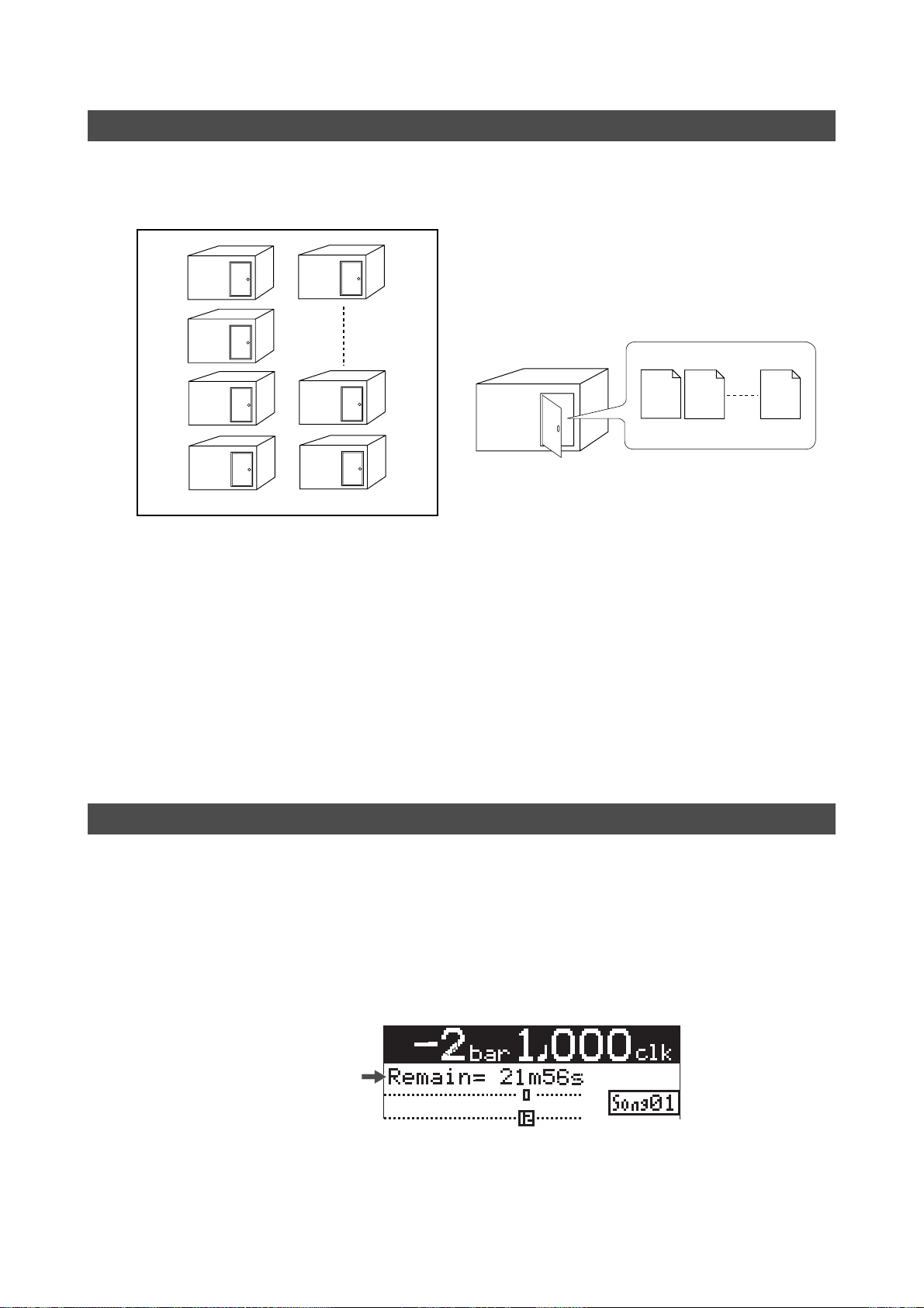
About song
To understand songs, imagine separated rooms as shown below. Each room can be regarded as
a song. With the MR-8mkII, you can create up to 99 rooms (songs) on the CompactFlashTM Card
(although the available space may limit the number of songs).
Song01
Song02
Song03
Song05
Song98
Recorded track data is stored in a song as mono WAV
files, as shown below.
Track 1
Track 2
Track 8
Song01
WAV files
Song04
Song99
Each song is independent on a CompactFlashTM Card and you can record, play back or edit a song
without affecting other songs. You can give a desired song name for managing recorded songs
(see pages 23 and 91).
Recorded track data is stored in a song as mono WAV files.
The MR-8mkII can convert the two WAV files recorded on tracks 7 and 8 (L and R) to a stereo
WAV file (see page 115).
You can export the converted stereo WAV file to your USB-connected personal computer, and
use the file by a music software application or make an original audio CD on the computer using
a CD burn software application. You can also burn an audio CD by using an external CD-R/RW
drive connected via the [USB HOST] port of the MR-8mkII (see page 115 and 123).
Remain (recordable space left on the CompactFlash
TM
Card)
"Remain" shows how much time you can further record audio data to the available space left on
the CompactFlashTM Card.
As described earlier, the MR-8mkII stripes ABS time from 0m 00s 000ms to 99m 59s 999ms at
maximum for each song. However, the remaining time (= available recording time left) depends
on the available space on the CompactFlashTM Card in actual use. The remaining time is shown as
in the screen example below during recording or record standby. Note that it shows the remaining time for recording onto a mono track.
Remain value
A "mono" track means a single track. Therefore, you can calculate the remaining time for recording to more than one track by dividing the displayed time by the number of tracks. Note that the
remaining time shown on the screen is an approximate time.
13
Page 14
MR-8mkII Owner’s Manual (Read this chapter first!)
Bar/beat mode
The beginning of a song
0m00s000ms
(ABS ZERO)
0m03s000ms 0m06s000ms
1bar 1 000clk
3bar 1 000clk
-2bar 1 000clk
ABS time mode
Time base
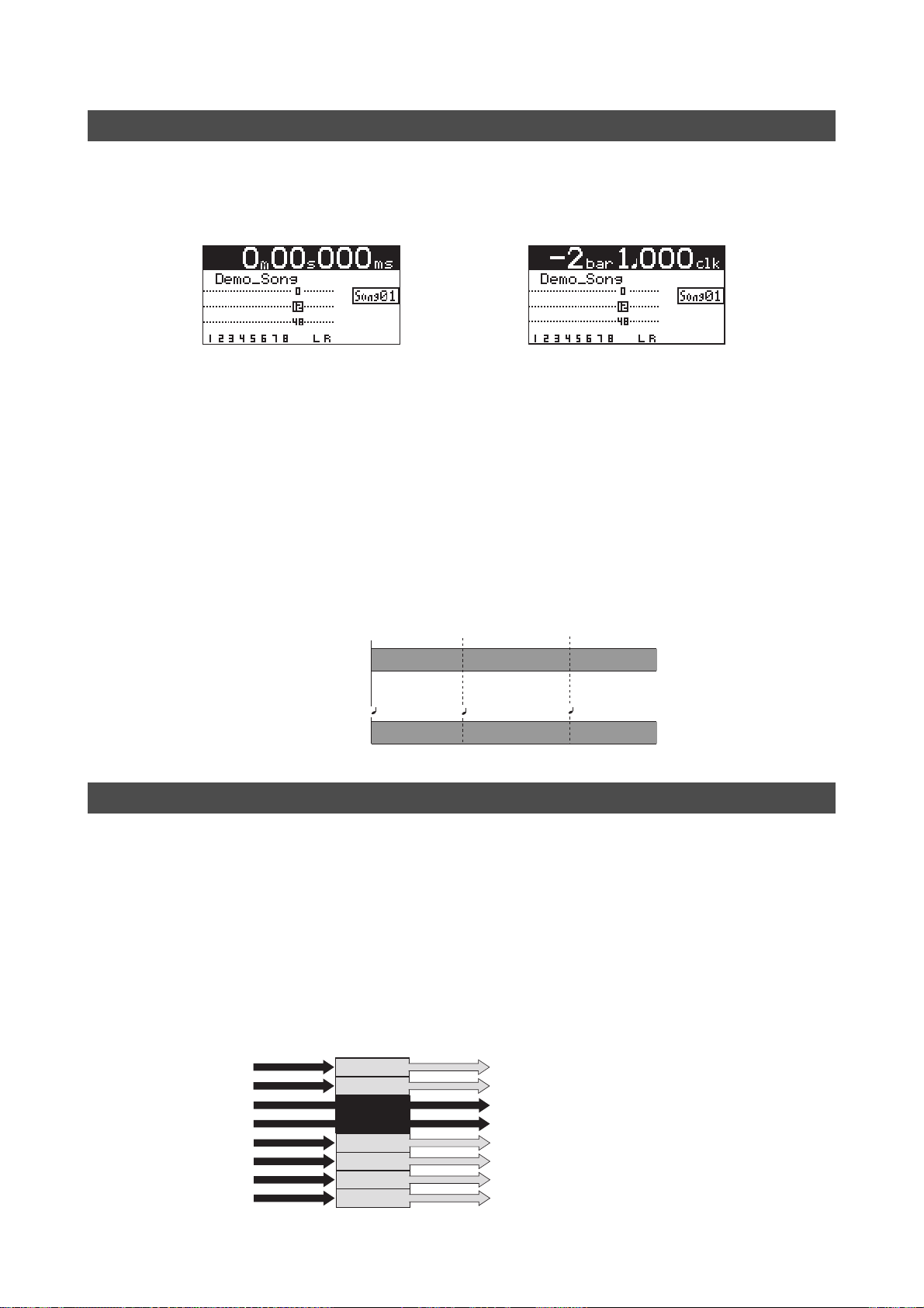
The term, "time base", is used as the reference of recorder position information.
Using the [TIME BASE SELECT] key, you can select from among two time base modes: ABS time
and bar/beat mode. Each screen example below shows the recorder is located at the beginning of
a song in each time base mode.
<Time (ABS time) mode>
<Bar/beat mode>
Time (ABS time) mode:
ABS time stands for Absolute time, which is "striped" on the CompactFlashTM Card when creating
a song. It starts from 0m 00s 000ms (=ABS zero, the beginning of a song) and ends by 99m 59s
999ms at maximum.
Bar/beat mode:
The bar/beat/clock information is created according to the internal tempo map.
The ABS zero position is set to "bar -2/beat 1/clk 000" by default (this is called "bar offset").
The MR-8mkII determines the bar/beat/clock value in a song in referenced to the bar offset, as
well as the time signature map and tempo map. You can set the bar offset between bar 1 to bar
-8 via the menu mode (see page 81). The figure below shows the relation between two time base
modes.
Input monitor and repro monitor
Each of the MR-8mkII tracks has two output modes: repro monitor and input monitor.
In the repro monitor mode, the track playback signal is output. So if you want to listen to the
track playback sound, select the repro monitor mode.
In the input monitor mode, the input signal fed to the track is output. So you can check the level
of the input signal to be recorded.
To enter a MR-8mkII track to input monitor mode, press the appropriate [REC SELECT] key to
arm the track (i.e. make the track record-ready), then press only the [RECORD] key to enter the
"RECORD READY" mode or press both the [RECORD] and [PLAY] keys simultaneously to start
recording.
Input signals for
recorder tracks
Track 3
Track 4
Output signals from
Track 1
Track 2
READY
READY
Track 5
Track 6
Track 7
Track 8
recorder tracks
Playback signal (repro monitor)
Playback signal (repro monitor)
Input signal (input monitor)
Input signal (input monitor)
Playback signal (repro monitor)
Playback signal (repro monitor)
Playback signal (repro monitor)
Playback signal (repro monitor)
14
Page 15
MR-8mkII Owner’s Manual (Read this chapter first!)
[TRIM] control
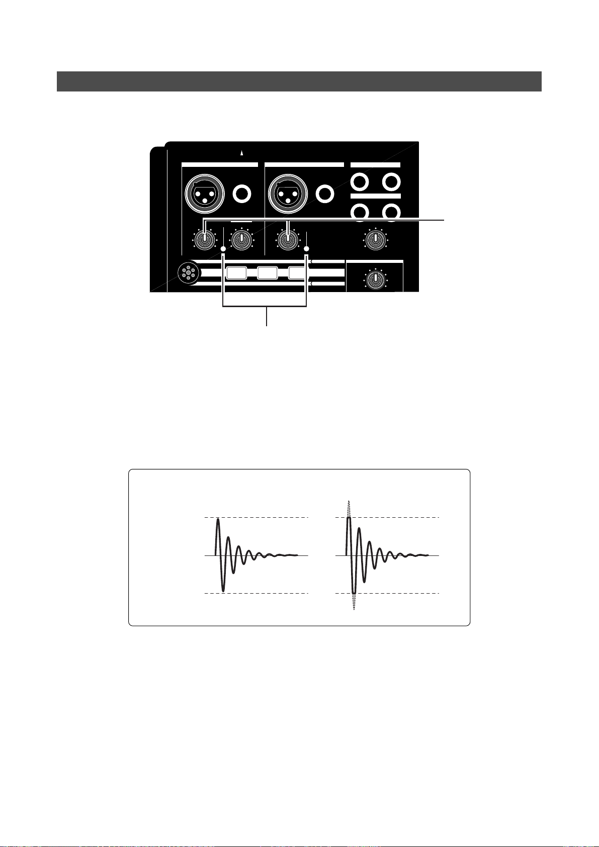
You must pay great attention to the [TRIM] control adjustment when recording to the MR-8mkII.
INPUT A SELECT
INPUT A INPUT B
UNBAL
/GUITAR
GUITAR
DISTORTION
PEAK
MIN
MIC
MAX
BRIT STACK US METAL 60'S COMBO
LINE
TRIM
BAL
MIC
LINE
TRIM
MIC
TUBECONDENSERDYNAMIC
UNBAL
PEAK
MIC SIMULATION
INPUT A
AMP SIMULATION
BAL
ST OUT
L
PHONES
1
PHONES VOL
MAX
MIN
EFFECT
REVERB/DELAY TIME
R
2
[TRIM] control
PEAK LED
The analog signal received at each input ([INPUT A] and [INPUT B]) is sent to the TRIM control,
by which the signal level fed to the A/D converter of the MR-8mkII is controlled.
You can check this level by the PEAK indicator. If the level is too high, the PEAK indicator lights,
while you may hear the sound distorted or noisy. This distortion (noise) generated at this stage
cannot be eliminated, therefore, adjust the TRIM control properly so that the PEAK indicator
does not light at the loudest part of the input signal.
Proper level
Clipping level
Clipping level
The level is too high.
15
Page 16

MR-8mkII Owner’s Manual (Read this chapter first!)
16
Page 17

MR-8mkII Owner’s Manual (Preparation)
Preparation
This chapter describes preparation for recording, playback and editing using the MR-8mkII. The chapter is comprised of the following
sections: "Preparation of recording media", "Preparation of power
supply" and "Creating a new song". Read this chapter before using
the MR-8mkII for the first time.
17
Page 18
MR-8mkII Owner’s Manual (Preparation)
Preparation of power suppl y
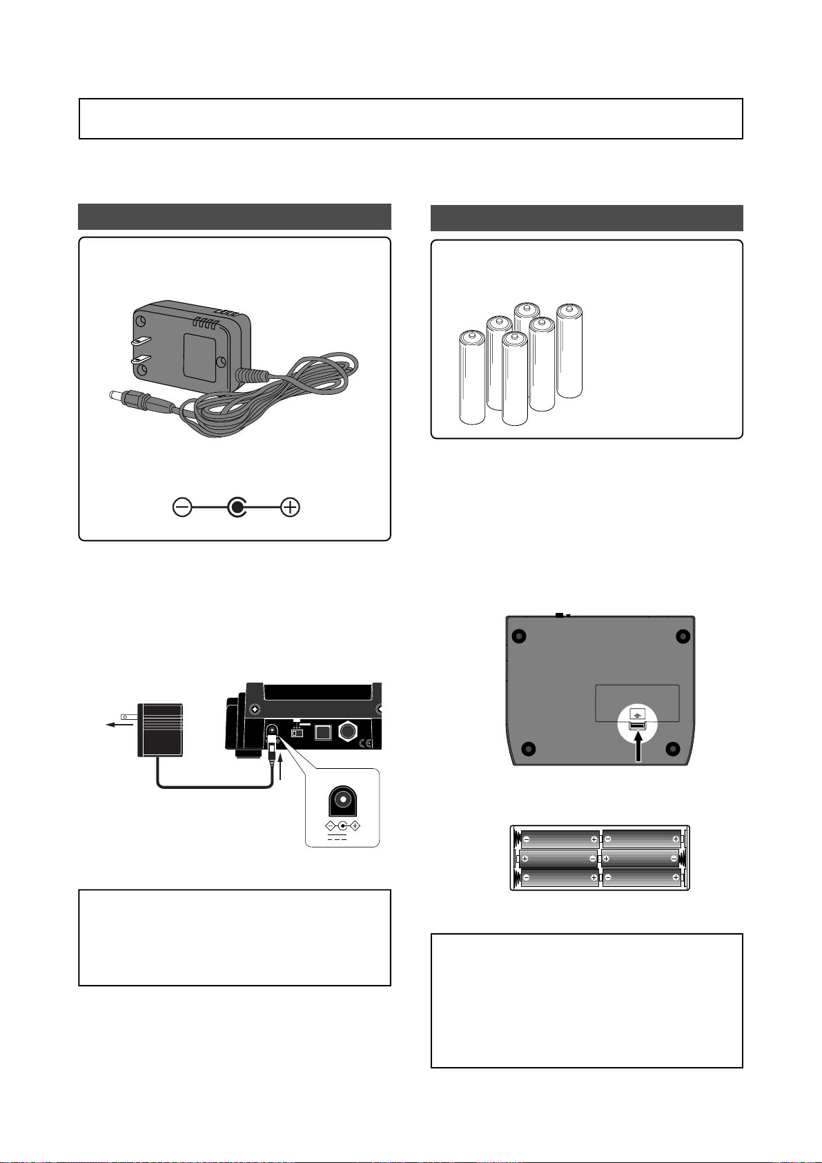
The MR-8mkII can run on the supplied AC adaptor (Model AD-12A) or alkaline batteries. When
preparing power supply, make sure that the MR-8mkII [POWER] switch is set to off.
Preparing the AC adaptor
<Important!>:
Do not use an AC adaptor which has different voltage or polarity characteristics.
The polarity of the supplied AC adaptor is center plus/outer minus.
Connect the plug of the supplied AC adaptor to
the [DC IN] connector on the MR-8mkII rear
panel firmly.
After making connection above, connect the AC
adaptor to the AC outlet of appropriate voltage.
Use only the supplied AC adaptor.
Preparing batteries
<Note>:
Purchase 6 size AA alkaline batteries. Do not use
manganese batteries.
The battery compartment is located on the bottom of the MR-8mkII. Install batteries correctly
by following the procedure below.
1) Place the MR-8mkII upside-down on a soft
2) Remove the battery compartment cover on the
No battery is supplied with the MR-8mkII.
The continuous usable
time is approximately four
hours. However, the actual usable time may differ depending on the condition in which the MR8mkII is used.
surface (such as on a soft cloth).
bottom by pushing the tab in the direction of the
arrow in the figure below and lifting up the co ver .
Model AD-12A
ON
DC IN
LIGHT
OFF
AC outlet
<Note>:
If you connect the AC adaptor to the MR-
POWER USB FOOT SW
12V
[DC IN] connector
DC IN
12V
8mkII while batteries are housed in the battery
box, the MR-8mkII runs on the AC adaptor. If you
disconnect the AC adaptor in this condition, the
MR-8mkII switches to run on batteries.
OPEN
3) Install batteries as shown below.
Make sure to install batteries in the correct
direction.
4) Place back the battery compartment cover to the
original position.
<Notes on batteries>
* Do not leave exhausted batteries in the battery
compartment. Old batteries may leak caustic
chemicals, which causes trouble of the unit.
We recommend removing batteries even if they
are new when you do not use the MR-8mkII for
a long period of time.
* Do not mix old and new batteries together.
18
Page 19
MR-8mkII Owner’s Manual (Preparation)
Preparation of recording media
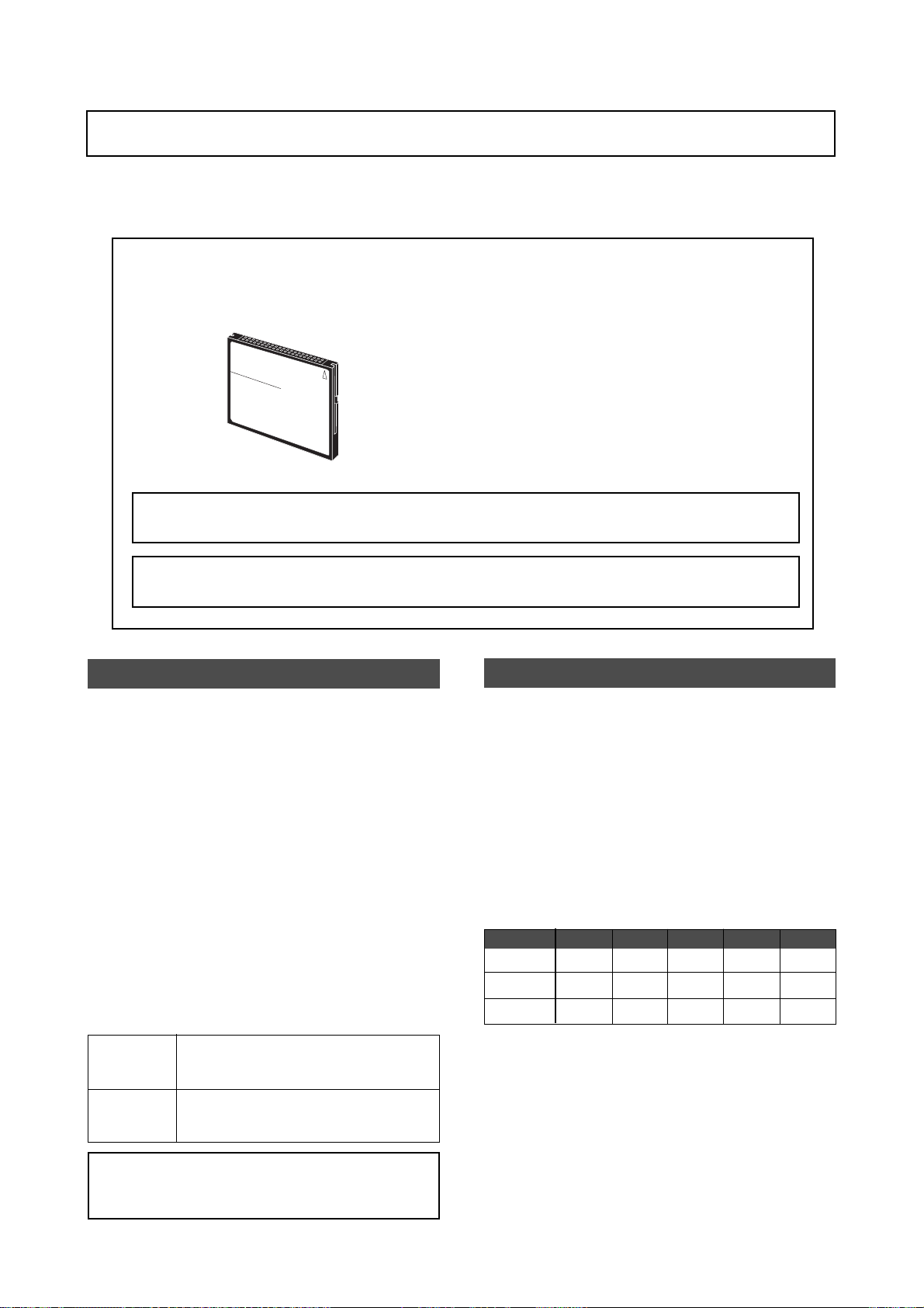
The MR-8mkII uses a CompactFlashTM card as a recording medium (see the figure below).
In some countries, a formatted (or unformatted) CompactFlashTM card is supplied with the MR8mkII, whereas in other countries, no CompactFlashTM card is supplied with the MR-8mkII.
<About operation-confirmed CompactFlashTM cards>
You can get the information of operation confirmed cards from your dealer or the
nearest Fostex service station or the Fostex website (see below).
COMPACTFLASH CARD
Fostex website:
http://www.f oste x.com
Image
<Note>:
(CompactFlash
<Note>:
operation confirmed, the MR-8mkII may malfunction.
The MR-8mkII has two song modes: Normal and
LP modes. You can choose the desired mode
when making recording.
The Normal mode provides higher audio quality, while the LP mode provides longer recording time (see the table below).
The song mode can be set for each song. Each
time you create a new song on a CompactFlash
card, you can set the desired song mode.
If a formatted card is supplied with your MR8mkII, a song of the Normal mode is created on
the card. When you use an unformatted card
(regardless of whether it is supplied with the
MR-8mkII or it is purchased separately), you can
set the song mode when formatting the card (see
page 23).
CompactFlash is a trademark of San Disk Corporation in the USA and is licensed to CFA
TM
Association).
Only use operation confirmed CompactFlashTM cards. If you use a card which is not
About song modes
TM
About recording time of a card
The total recordable time of a CompactFlash
card depends on the capacity of the card as well
as the song mode of each song.
The following table shows the approximate recordable time (in minutes) for both the Normal
and LP modes (each value in parentheses shows
the time in the LP mode). Use the table as reference when you purchase a card.
We recommend using a CompactFlash
TM
128 MB or higher capacity for the MR-8mkII.
Capacity
128MB
256MB
512MB
Mono
24 (48)
48 (96)
96 (193)
2-track
12 (24)
24 (48)
48 (96)
4-track
6 (12)
12 (24)
24 (48)
6-track
4 (8)
8 (16)
16 (32)
TM
card of
8-track
3 (6)
6 (12)
12 (24)
Normal
mode
LP mode
<Note>: Song data recorded in the LP mode can-
not be burned to a CD-R/RW disc in the audio CD
(CD-DA format) using an external CD-R/RW drive.
Provides higher audio quality at 44.1-kHz/
16-bit. This is the default setting.
Provides longer recording time with 22.05kHz/16-bit audio.
* Each time value above shows an approximate value (in
minutes).
* Each value in parentheses shows a value in the LP mode.
19
Page 20
MR-8mkII Owner’s Manual (Preparation)
Handling of CompactFlashTM cards
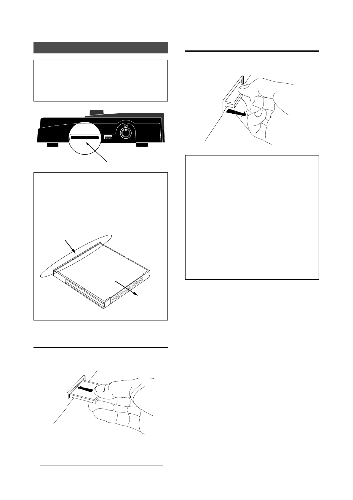
<Important!>:
make sure that the power of the MR-8mkII is off.
If you insert or remove a card when the power is
on, the card may be damaged or the recorded
data may be destroyed.
<Note>:
the card with the rear side down.
On the rear side, there is a small protruding edge
on which you can put your fingertip to pull out
the card, as shown in the figure below. Do not
insert a card upside down. Doing so may damage the card.
Protruding edge
When inserting or removing a card,
COMPACTFLASH CARD
When you set a card to the slot, insert
MIDI OUTUSB HOSTCOMPACTFLASH CARD
Card slot
How to remove a CompactFlashTM card
Place your fingertip to the protruding edge on
the rear side of the card and pull it forward gently.
<Handling of CompactFlashTM cards>
• Do not keep CF cards in the following
circumstances.
* In a moist or dusty place
* In a extremely hot place such as in front of
a heating appliance
* In the direct sunshine
* In the closed car in summer
* In a strong magnetic field or near a device
which generates a magnetic field
Rear side
Inserted direction
How to insert a CompactFlash
TM
card
With the surface side up, insert a card gently
until it cannot go further.
• Do not drop a card or give it a strong shock.
• Do not step on a card or put a heavy thing on
a card.
<Important!>:
wrong direction or push a card with excessive
force.
Do not insert a card in the
20
Page 21
MR-8mkII Owner’s Manual (Preparation)
Turning on the power
When peripheral devices are connected to the
MR-8mkII, turn on the power of eac h device in
the following order.
• Turn down the [MASTER] fader of the
MR-8mkII.
• Turn on the external device which send
signals to the MR-8mkII input(s).
• Turn on the MR-8mkII.
• Turn on the external monitor device (amplifier ,
powered speaker, etc.).
After preparing power supply (the AC adaptor or
batteries), turn on the MR-8mkII by sliding the
[POWER] switch the to "ON" position.
The following description assumes that a formatted or unformatted CompactFlashTM card is inserted
to the card slot.
Turn on the MR-8mkII power by switching the
[POWER] switch on the MR-8mkII rear panel to
"ON".
ON
DC IN
LIGHT
OFF
POWER USB FOOT SW
12V
INT MIC
INPUT A SELECT
MIC/LINE
GUITAR
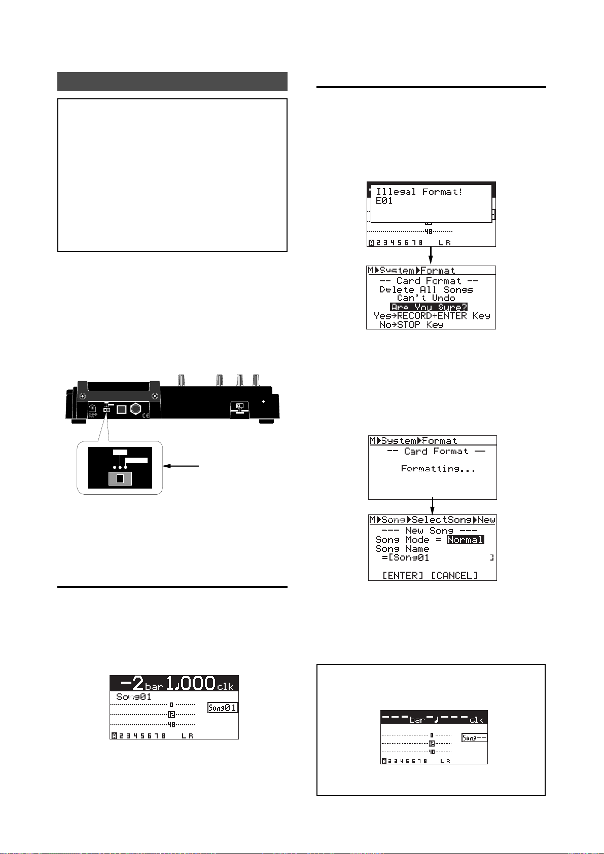
When an unformatted is inserted:
When turning on the MR-8mkII while an
unformatted CompactFlash
display shows "Illegal Format! E01", followed by
the Card Format screen as below. This shows that
the MR-8mkII recognizes the card is unformatted
and automatically enters the "Card Format" item
in the "System" menu of the MENU mode.
If the screen above is shown, follow the instruction on the screen. That is, press the [MENU/ENTER] key while holding down the [RECORD] key.
The MR-8mkII starts formatting the card. When
formatting completes, the MR-8mkII enters the
"Song" menu of the MENU mode and the display
changes to show the screen for creating a new song
(Song01).
TM
card is inserted, the
ON
LIGHT
OFF
Set to "ON".
When turning on the MR-8mkII while a card is inserted, the MR-8mkII starts up and shows an appropriate screen as below depending on whether
the card is formatted or unformatted.
When a formatted card is inserted:
When turning on the MR-8mkII while a formatted
CompactFlash
the Home screen as below.
On a formatted card, a song of the Normal mode
exists. While the home screen is shown, you are
ready for making recording with the MR-8mkII (see
page 35).
TM
card is inserted, the display shows
On this screen, you can create a new song with the
desired song mode (Normal or LP) and song name.
See steps 5 to 9 in "Creating a new song" on page
23 for details about how to select the song mode
and how to set a song name.
<Note>:
ing a CompactFlash
If you turn on the power without insert-
TM
card, the display shows the
screen below.
The name of the song is "Song01" be default, however, you can change it later (see page 91). You
can make up to 99 songs on a CompactFlash
TM
card
(see page 23).
In this case, turn off the power, insert a
TM
CompactFlash
card, and turn on the power again.
21
Page 22
MR-8mkII Owner’s Manual (Preparation)
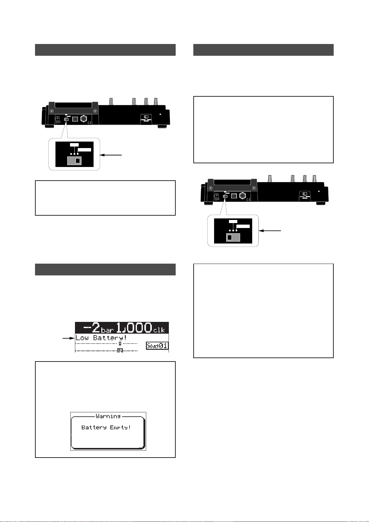
Backlight facility
The MR-8mkII provides a backlight facility, which
allows improving observation in poor lighting conditions. To turn on the backlight, set the [POWER]
switch to the "LIGHT" position.
ON
DC IN
LIGHT
OFF
POWER USB FOOT SW
12V
ON
LIGHT
OFF
"LIGHT" position
<Note>:
turning on the backlight when running the MR8mkII on batteries. Turning on the backlight consumes batteries, making the battery life shorter.
The MR-8mkII also has a facility for adjusting the
display contrast. See page 32 for details.
Unless really needed, we recommend not
INT MIC
INPUT A SELECT
MIC/LINE
GUITAR
Turn off the power
When turning off the power, make sure that the
MR-8mkII is stopped.
If any peripherals are connected, turn off the power
of each unit in the reverse order of the order for
turning on the power.
<Note>:
8mkII is accessing the card, there is a risk for destroying the recorded song or the whole card.
You do not need any shutdown operation before
turning off the MR-8mkII. The MR-8mkII keeps
data recorded just before turning off the power.
So you can concentrate on the recording operation.
If you turn off the power while the MR-
ON
DC IN
LIGHT
OFF
POWER USB FOOT SW
12V
OFF
ON
LIGHT
INT MIC
INPUT A SELECT
MIC/LINE
GUITAR
"OFF" position
Low battery indication
While running the MR-8mkII on batteries, if the
battery voltage is getting low, "Low Battery!" starts
flashing in the song name field. In this case, interrupt the operation and replace batteries with new
ones.
Flashing
<Note>:
tery!" starts flashing, batteries are completely exhausted finally and the display shows the screen
below, while the MR-8mkII accepts no operation.
We recommend replacing batteries before they are
completely exhausted.
If you continue operation after "Low Bat-
<Notes when peripheral devices are connected>
When peripheral devices are connected to the
MR-8mkII, turn off the power of each device in
the following order.
• Turn off the external monitor device (amplifier,
powered speaker, etc.).
• Turn off the MR-8mkII.
• Turn off the external device which send
signals to the MR-8mkII input(s).
22
Page 23
MR-8mkII Owner’s Manual (Preparation)
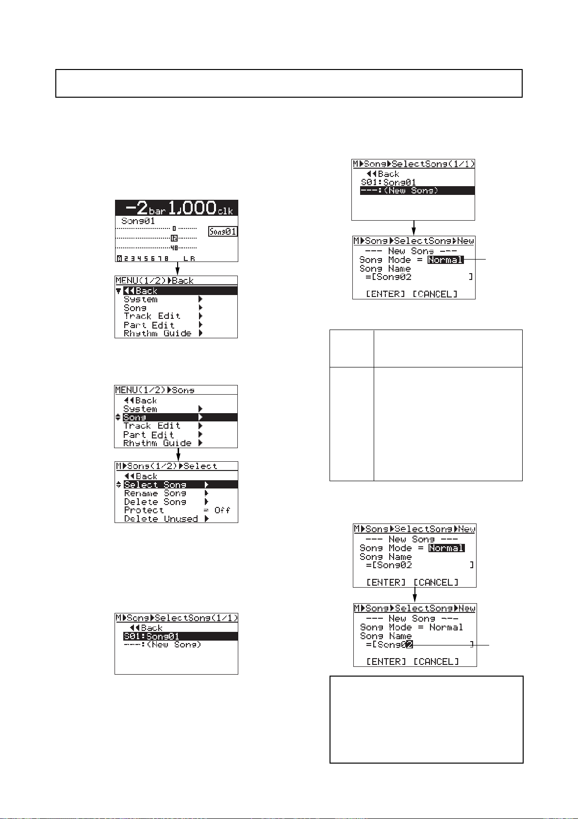
Creating a new song
You can create a new song by following the procedure below. In the following procedure, it is assumed that
Song01 is loaded and the recorder is at the beginning of the song. If a card is unformatted, f ormat the car d b y
following the procedure on page 21, then execute steps 5) thr ough 9) below f or setting the song mode and song name.
1) While the recorder is stopped, press the
[MENU/ENTER] key.
The display now shows the first page of the
menu selection screen.
Flashing
The "Normal" song mode is the standard mode.
The LP mode allows longer recording.
With the Normal mode, audio is re-
2) Rotate the jog dial to select "Song" and press
the [MENU/ENTER] key.
The display now shows the song menu screen.
Normal
LP
corded at 44.1kHz Fs, 16-bit. This is
the standard mode.
With the LP mode, audio is recorded
at 22.05kHz Fs, 16-bit. It allows longer
recording time, while the audio frequency range is narrower.
<Note>: Song data recorded in the
LP mode cannot be burned to a CDR/RW disc in the audio CD (CD-DA
format) using an external CD-R/RW
drive.
3) While "Select Song" is highlighted, press the
[MENU/ENTER] key.
The display now shows the screen for
selecting a song. You can see the list of the song
numbers/names on the card.
In the screen example below, only Song01 is
created. "---:(New Song)" is used to create a new
song.
4) Rotate the jog dial to select "---:(New Song)" and
press the [MENU/ENTER] key.
The display now shows the screen for setting
the song mode and song name of the new song.
The default song mode is "Normal", while the
default song name is "Song02" (just after the
card has been formatted, the default song name
is "Song01").
5) Rotating the jog dial to select the desired song
mode and press the [MENU/ENTER] key.
You can now enter the desired song name.
Flashing
<Note>:
name ("Song02" in the example above). You
can also edit the song name after creating a
song (see page 91). If you do not change the
default song name, press the [MENU/ENTER]
key twice in step 5) above (which results the
same as step 9) in the next page).
You may not edit the default song
23
Page 24
MR-8mkII Owner’s Manual (Preparation)
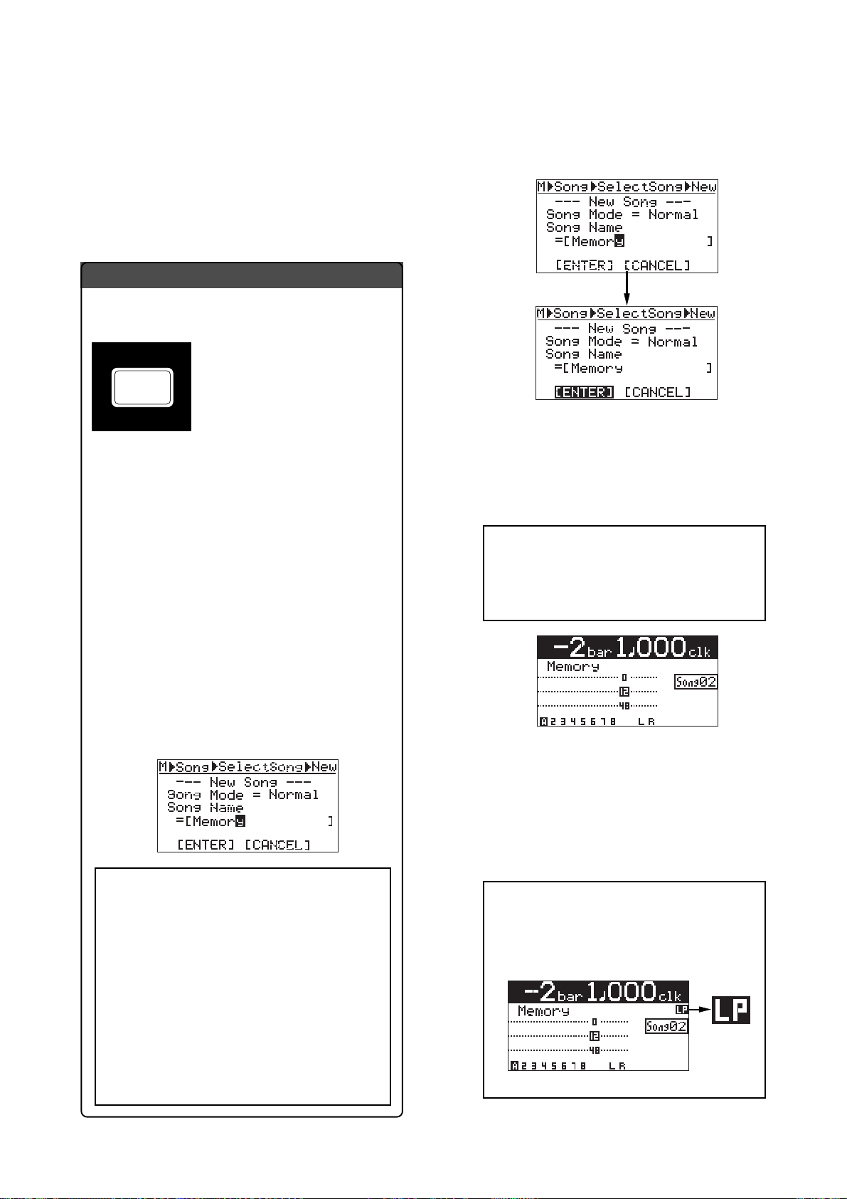
6) Press the [UNDO/REDO] / [DELETE] key
repeatedly until the entire default name is deleted.
7) Use the character entry keys to enter a desired
song name.
See "How to enter a name" below for details
about how to enter a song name. A song name
can be up to 16 characters.
How to enter a name
<Character entry keys>
Some keys on the MR-8mkII top
PLAY MODE
STU7
<Example of song name entry>
The following example shows how to enter "Memory"
as a song name.
1. Using the [MNO5] key, enter "M".
2. Using the [DEF2] key, enter "e".
3. Using the [MNO5] key, enter "m".
panel act as character entry keys
in the MENU mode. For example,
the [PLAY MODE] key (shown at
the left) can be used for entering S,
T, U, s, t, u and 7. Each press of a
character entry key switches the
character to be entered from among
those assigned to the key.
8) After entering the desired name, press the
[MENU/ENTER] key.
The name is set, while the cursor moves to
"[ENTER]".
9) While "[ENTER]" is highlighted, press the
[MENU/ENTER] key.
The second song (whose song name is
"Memory") is created, while the MR-8mkII
exits the MENU mode and the display shows
the home screen of the newly created song02.
<Note>:
existing song, the display shows "Illegal Song
Name!" and returns to the song name editing screen. In such a case, enter a different
name.
If you enter the same name as an
4. Using the jog dial, move the cursor.
5. Using the [MNO5] key, enter "o".
6. Using the [PQR6] key, enter "r".
7. Using the [YZ9] key, enter "y".
<Notes>
• Pressing the different character entry key
automatically moves the cursor right.
If the two adjacent characters are assigned
to the same key, use the jog dial to move
the cursor after entering the first
character (as shown in step 4 above).
• For a song name with eight or less
characters, you cannot use "+" (for
example, "AAA+BBB" is illegal). You can
use "+" for a song name with more than
eight characters (for example,
"AAA + BBBBB" is legal).
As described above, you can create more than
one song before you start recording.
Note that when more than one song is created,
you must select the desired song before you
start recording or editing.
See "Song management" on page 90 for details
about how to select the desired song.
<Note>:
loaded, "LP" is lit on the home screen as
below, which allows you to recognize the
song mode.
When a song of the LP mode is
24
Page 25

MR-8mkII Owner’s Manual (Names and functions)
Names and functions
This chapter describes the names and functions of the controls,
keys, connectors, etc. on the MR-8mkII top panel, rear panel and
side panel, as well as details of the display. See this chapter whenever you want to know the function of a control, key, etc.
25
Page 26
MR-8mkII Owner’s Manual (Names and functions)
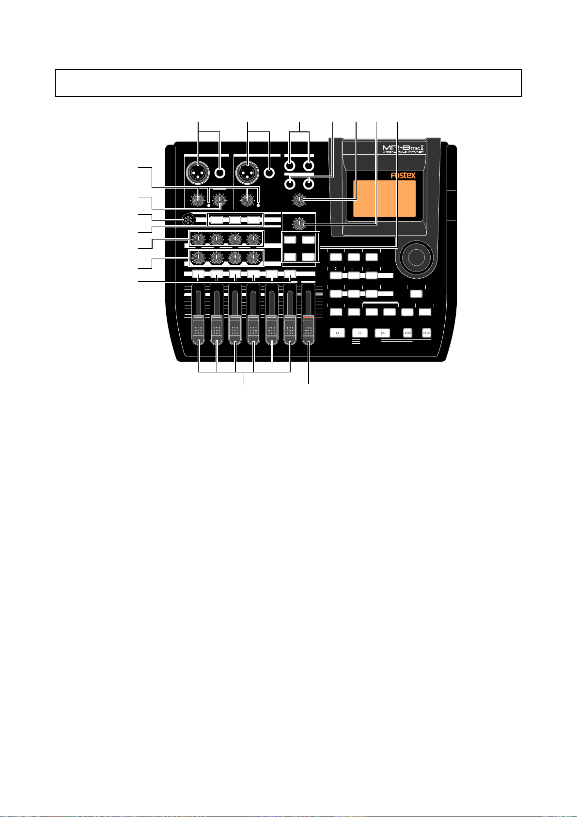
Top panel 1
16
15
14
13
12
11
10
1
INPUT A SELECT
INPUT A INPUT B
BAL
DISTORTION
PEAK
TRIM
LINE
MIN
MIC
MIC
BRIT STACK US METAL 60'S COMBO
010
RL
LR LR LR
1 2 3 4 5/6 7/8 MASTER
MAX
MIN
234
UNBAL
/GUITAR
GUITAR
MAX
100100100
UNBAL
BAL
TRIM
PEAK
LINE
MIC
MIC SIMULATION
TUBECONDENSERDYNAMIC
INPUT A
AMP SIMULATION
EFFECT SEND
PAN
9
ST OUT
L
PHONES
1
PHONES VOL
MAX
MIN
EFFECT
REVERB/DELAY TIME
MIN MAX
PLATE DELAY
REC SELECT
67
5
R
2
HALLROOM
RHYTHM
TIME BASE
GUIDE
1-4
1-6
MAX
AUTO PUNCH
MIN
PQR6
CONTRAST
SELECT
5/6
7/8
1-8
MNO5JKL4
PLAY MODE
NEW
SONG
STEREO
7/8
WAV FILE
GHI3DEF2ABC1
BRIGHTNATURALPOWERFUL
A / IN B / OUT
LOCATE REC END
LOCATE ABS ZERO
A-B PLAY
BOUNCE
MASTERING
LOCATE
PLAYSTOPRECORD REWIND F FWD
MENU/ENTER
STORE
UNDO/REDO
DELETE+-_0YZ9VWX8STU7
8
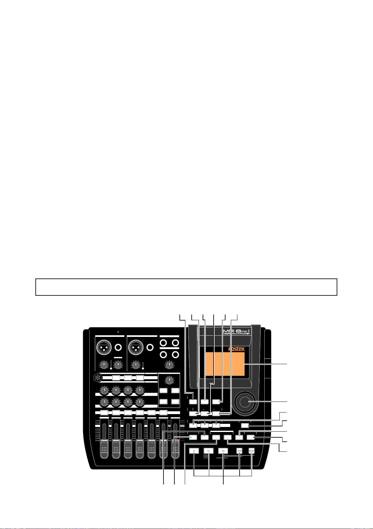
1. [INPUT A] input connectors
(XLR and phone)
Both the [BAL] XLR connector and [UNBAL/
GUITAR] phone jack are provided (if you
connect sources to both the XLR connector
and PHONE jack, the phone input jack priority). You can connect a guitar, microphone,
keyboard, etc. (a guitar should be connected
to the PHONE jack). To use either of the [INPUT A] connectors, set the [INPUT A SELECT]
switch to “MIC/LINE” or “GUITAR” (you cannot use it when the [INPUT A SELECT] switch
is set to “INT MIC”).
To record a mono source, use only the [INPUT A] section. To record a stereo source,
use both the [INPUT A] and [INPUT B] sections (see page 36).
2. [INPUT B] input connectors (XLR and phone)
Both the [BAL] XLR connector and [UNBAL]
phone jack are provided (if you connect
sources to both the XLR connector and
PHONE jack, the phone input jack priority)..
You can connect a microphone, keyboard,
etc. This section is used only when recording a stereo source. When recording a mono
source, this section is not used (see page 36).
3. [STEREO OUT] jacks (L, R)
These jacks output the stereo (L and R) buss
signals. Connect these jacks to the monitoring equipment or master recorder (see page
44).
4. [PHONES] jacks (1, 2)
Two jacks (1 and 2) are provided. You can
use two pairs of stereo headphones with the
MR-8mkII (see page 36).
5. [PHONES V OL] control
Adjusts the headphone output level.
6. [REVERB/DELA Y TIME] control
This control adjusts the reverb time or delay time. When you select "ROOM", "HALL"
or "PLATE" for the effect type, it adjusts the
reverb time.When you select "DELAY", it
adjusts the delay time (See page 62).
7. [EFFECT] keys
These keys are used to select the effect type.
You can select from three reverb types
(ROOM, HALL and PLATE) and a delay
(DELAY). The selected key is lit (see page 61).
8. [MASTER] fader
Adjusts the stereo (L and R) buss output
level.
26
Page 27
MR-8mkII Owner’s Manual (Names and functions)
9. Track faders 14. Internal Microphone
Each fader adjusts the track playback level.
Each of track faders 5/6 and 7/8 controls
the stereo signal (see pages 38 ~ 44).
10. [REC SELECT] keys
Used to select the recording track(s). You can
record onto up to two tracks simultaneously.
Pressing a key arms or unarms the corresponding track(s). Tracks 5/6 or 7/8 are
armed or unarmed simultaneously (see
pages 38 ~ 44).
11. [PAN] controls
Control panning for tracks 1 through 4.
You can make recording using the internal
microphone by setting the [INPUT A SELECT]
switch on the rear panel to “INT MIC” (see
page 36). When you use the internal microphone, you cannot use the insert effect.
15. [DISTOR TION] contr ol
Controls the amount of the distortion effect
for a guitar connected to the [XLR] connector or [UNBAL/GUITAR] jack (phone type)
on the [INPUT A] channel.
This control is effective only when the [INPUT A SELECT] switch is set to "GUITAR" (see
pages 36 and 38).
12. [EFFECT SEND] controls
Control the amount of signals from tracks 1
through 4 sent to the internal effect (reverb
or delay) (see page 62).
13. Insert effect selection keys
Used to select the insert effect (mic simulation or amp simulation) for the signal from
the [INPUT A] jack.
When setting the [INPUT A SELECT] switch
on the rear panel to "MIC/LINE", you can
use the mic simulation effect. When setting
the switch to "GUITAR", you can use the
guitar amp simulation effect (see page 60).
INPUT A SELECT
INPUT A INPUT B
UNBAL
/GUITAR
BAL
GUITAR
DISTORTION
PEAK
TRIM
LINE
MIN
MIC
MIC
BRIT STACK US METAL 60'S COMBO
010
RL
LR LR LR
1 2 3 4 5/6 7/8 MASTER
MAX
MIN
BAL
TRIM
LINE
MAX
100100100
Top panel 2
17 18
ST OUT
L
R
PHONES
2
1
UNBAL
INPUT A
PAN
PHONES VOL
MAX
MIN
EFFECT
REVERB/DELAY TIME
MIN MAX
PLATE DELAY
REC SELECT
HALLROOM
PEAK
MIC
MIC SIMULATION
TUBECONDENSERDYNAMIC
AMP SIMULATION
EFFECT SEND
16. [TRIM] controls / [PEAK] indicators
Each control adjusts the input gain of the
corresponding input channel (see pages 36
and 38 ~ 44).
Each indicator lights when the input signal
is overloaded (see page 15). You should adjust the input gain using the [TRIM] control
so that the [PEAK] indicator does not light.
22212019
23
RHYTHM
TIME BASE
GUIDE
1-4
1-6
MAX
AUTO PUNCH
MIN
PQR6
CONTRAST
SELECT
5/6
7/8
1-8
MNO5JKL4
PLAY MODE
NEW
SONG
STEREO
7/8
WAV FILE
GHI3DEF2ABC1
BRIGHTNATURALPOWERFUL
A / IN B / OUT
LOCATE REC END
LOCATE ABS ZERO
A-B PLAY
BOUNCE
MASTERING
LOCATE
PLAYSTOPRECORD REWIND F FWD
MENU/ENTER
STORE
UNDO/REDO
DELETE+-_0YZ9VWX8STU7
24
25
26
27
28
29
33
3231
27
30
Page 28

MR-8mkII Owner’s Manual (Names and functions)
17. [RHYTHM GUIDE] key
Switches on/off of the rhythm guide function (see page 76). Each press of the switch
alternates on and off. A long press of the
key enters the rhythm guide menu, in which
you can set the rhythm guide parameters.
18. [BOUNCE 1-4 > 5/6, 1-6 > 7/8] / ABC1 key
Selects the bounce mode (see page 68).
In the menu mode, this key is used for character entry of A, B, C, a, b, c and 1.
19. [TIME BASE SEL] ke y
Selects the time base shown on the display
(see page 32). Each press of the key switch
between "time" and "bar/beat".
20. [BOUNCE 1-8 > NEW SONG] / DEF2 key
Selects the bounce mode (see page 73).
In the menu mode, this key is used for character entry of D, E, F, d, e, f and 2.
21. [CONTRAST] key
By rotating the JOG dial while holding down
this key, you can adjust the display contrast
(see page 32).
22. [7/8 > STEREO W AV FILE] /GHI3 key
This key is used when converting a mono
WAV file recorded on tracks 7/8 to a stereo
WAV file (see page 116). You can export the
stereo WAV file to your personal computer
over the USB connection (see page 118).
In the menu mode, this key is used for character entry of G, H, I, g, h, i and 3.
23. LCD display
This 132 x 64 dot LCD display shows various information (see page 31).
24. JOG dial
In the menu mode, rotating this dial selects
the item or numeric value.
25. [MASTERING] keys
Used to select the desired mastering effect
during track bounce or mixdown. You can
select from three effect types by pressing an
appropriate key (see page 63).
In the menu mode, the [POWERFUL] key is
used for character entry of J, K, L, j, k, l and
4, while the [NATURAL] key is used for character entry of M, N, O, m, n, o and 5.
26. [MENU/ENTER] key
Pressing this key enters the menu mode.
In the menu mode, while pressing this key
confirm the setting/selection.
27. [STORE]/+-_0 ke y
Stores the current recorder position (time
data) as the LOCATE A/IN or LOCATE B/OUT
point (see pages 51 and 56).
In the menu mode, this key is used for character entry of +, -, _ and 0.
28. [UNDO/REDO]/[DELETE] key
Used to undo or redo recording or editing
(see pages 39, 41, 43, 95 and 103).
Each press of the key alternates "undo" and
"redo". In the menu mode, this key is used
for deleting a character (see pages 23 and
91).
29. [LOCATE B/OUT]/GHI3 key
Pressing this key while holding down the
[STORE] key sets the LOCATE B point (or
punch out point) (see page 51 and 56).
In the menu mode, this key is used for character entry of G, H, I and 3.
30. Transport keys
[PLAY] key
Starts playback of the recorder.
Pressing this key while holding down the
[RECORD] key starts recording of the armed
(record-ready) track(s).
Pressing this key during recording exits recording.
[STOP] key
Stops the recorder.
By pressing the [PLAY], [REWIND] or [F FWD]
key while holding down the [STOP] key, you
can locate to a specific point or repeat playback as below.
• [STOP] + [PLAY] (A-B PLAY)
Repeats playback between the LOCATE A and
LOCATE B points (see page 46).
• [STOP] + [REWIND] (LOCATE ABS ZERO)
Locates to the beginning (ABS ZERO) of the
current song (see page 50).
• [STOP] + [F FWD] (LOCATE REC END)
Locates to the recording end of the current
song (REC END) (see page 50).
[RECORD] key
Pressing the [PLAY] key while holding down
the [RECORD] key starts recording of the
armed (record-ready) track(s).
By pressing only the [RECORD] key when any
track(s) is armed (in record-ready), the input signal(s) of the armed track(s) can be
monitored (i.e. input monitor mode). (see
pages 38 ~ 42).
28
Page 29
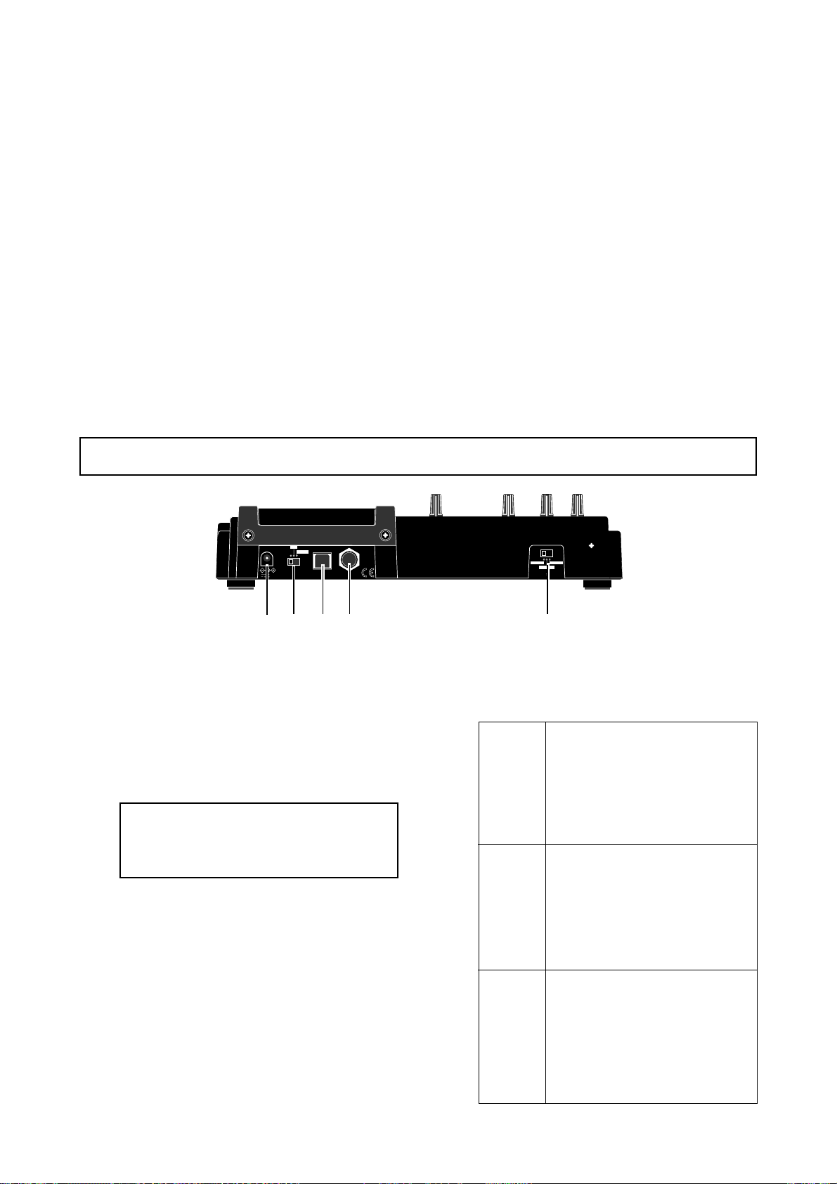
MR-8mkII Owner’s Manual (Names and functions)
[F FWD] key
Pressing this key fast forwards the recorder.
During playback, pressing this key starts 3 x
cueing (see page 46).
While holding down the [STOP] key, pressing this key locates to the recording end of
the current song (REC END) (see page 50).
[REWIND] key
Pressing this key rewinds the recorder.
During playback, pressing this key starts 3 x
reverse cueing (see page 46).
While holding down the [STOP] key, pressing this key locates to the beginning (ABS
ZERO) of the current song (see page 50).
This key is also used to go up the menu
screen layer while a menu screen is displayed.
Rear panel
31. [LOCATE A/IN] / VWX8 key
Pressing this key while holding down the
[STORE] key sets the LOCATE A point (or
punch in point) (see page 51 and 56).
In the menu mode, this key is used for character entry of V, W, X, v, w, x and 8.
32. [AUTO PUNCH] / PQR6 entry key
Turns on or off the auto punch mode (see
page 57).
In the menu mode, this key is used for character entry of P, Q, R, p, q, r and 6.
33. [PLAY MODE] / STU7 key
Selects a play mode. You can select from
among normal, auto play, auto return and
loop (see page 47).
In the menu mode, this key is used for character entry of S, T, U, s, t, u and 7.
ON
DC IN
LIGHT
OFF
POWER USB FOOT SW
12V
34 5
2
1
1. [DC IN] connector
Connect the supplied AC adaptor to this connector (see page 18).
2. [PO WER] switc h
Used to turn on or off the power.
By setting this switch to “LIGHT”, the backlight of the LCD display lights up (see page
22).
<Note>:
teries, we recommended not use the backlight, because the batteries are exhausted
quickly.
When driving the MR-8mkII by bat-
3. [USB] port (USB B type)
Used to connect with a personal computer
using a standard USB cable for song file data
transfer between the MR-8mkII and the personal computer (see page 118).
4. [FOOT SW] jac k (TRS phone jack)
Used to connect with an unlatched-type
footswitch (see page 55).
MIC/LINE
INT MIC
GUITAR
INPUT A SELECT
5. [INPUT A SELECT] switch
This switch must be set appropriately according to the input source of the [INPUT A] channel (see page 37).
Set the switch to this position when
the source is an external microphone
or line level source.
MIC/LINE
GUITAR
INT MIC
Both the [BAL] (XLR) and [UNBAL/
GUITAR] (phone) connectors can be
used. Y ou can also use the mic simulation insert effect.
Set the switch to this position when
the source is a guitar connected to
the phone connector.
Both the [BAL] (XLR) and [UNBAL/
GUITAR] (phone) connectors can be
used. You can also use the amp
simulation insert effect.
Set the switch to this position when
the source is the built-in microphone.
When the switch is set to the “INT
MIC” position, you cannot use the [INPUT A] connectors (both the [BAL]
and [UNBAL/GUITAR] connectors),
as well as the insert effect.
29
Page 30
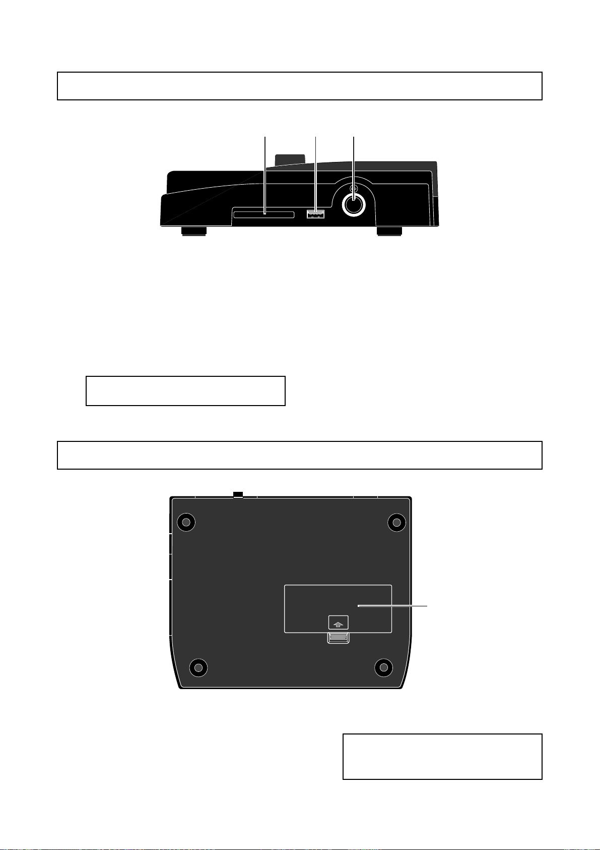
MR-8mkII Owner’s Manual (Names and functions)
Side panel
13
1. Card slot
A CompactFlashTM card is inserted to this slot
(see page 20).
2. [USB HOST] connector (USB A type)
Used to connect to an external CD-R/RW
drive for burning songs recorded by the MR8mkII to a CD-R/RW disc in the CD-DA (audio CD) format (see page 123).
<Caution>:
computer to the [USB HOST] port.
Do not connect your personal
2
MIDI OUTUSB HOSTCOMPACTFLASH CARD
3. [MIDI OUT] jack (DIN 5-pin connector)
Used to connect to a MIDI IN jack of an external MIDI device (such as a MIDI sequencer) (see page 85).
1. Battery compartment
To use the MR-8mkII with batteries, insert
six standard alkaline AA-type batteries to this
compartment (see page 18).
Bottom panel
OPEN
<Caution>:
long period of time, remove batteries to
prevent leakage in compartment.
1
If the MR-8mkII is not used for a
30
Page 31
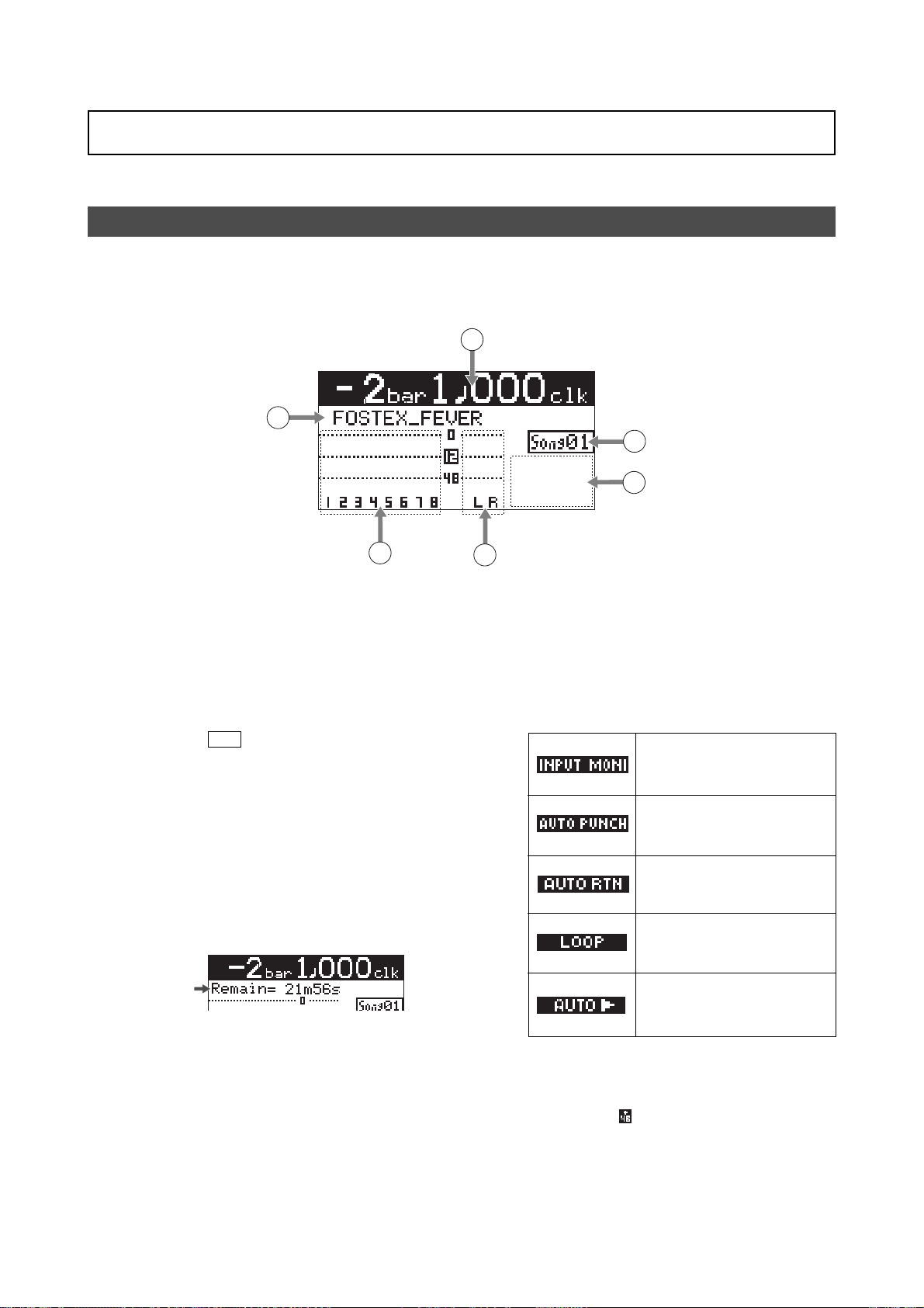
MR-8mkII Owner’s Manual (Names and functions)
LCD display
The following describes details about the LCD display, including screen contents and operation.
Home screen
When turning on the MR-8mkII, the display shows the startup screen (showing the startup status of the
MR-8mkII), followed by the "home" screen, which is similar to the one below. In this condition, the previously loaded song is loaded and the recorder is located at the beginning of the song.
The home screen provides the following information.
1
2
6
5
1. Time counter display
Time information of the current recorder position is shown in ABS or bar/beat mode (by
default, bar/beat). Using the [TIME BASE SELECT] key, you can select a desired time base
mode. When the recorder is moving (playing
back, fast forwarding, etc.), the appropriate
icon is also shown. While the hard disk drive is
in access, " ACC " lights up.
2. Character display
Normally, the name of the song currently
loaded is shown (up 16 characters can be
shown at a time).
It also shows following information.
• A name of the operation mode currently
being executed (such as "BOUNCE 1-6->7/8).
• A (not-so-serious) warning message
• The "Remain" time when at least one track is
record-armed (i.e. At least one of the
[REC SELECT] keys is active).
The remain time shows how much time you
can further record audio data onto a mono
track using the available space left on the hard
disk.
3. Track level displa y
The recording or playback levels of tracks 1
through 8 are shown. When a track is record
armed, the track number indication changes
to the source input channel (any of A and B).
3
4
4. Stereo buss (L and R) level displa y
During recording or playback, the output levels of the L/R stereo buss are shown.
5. Song status display
Lights up the following status icons when the
appropriate modes (functions) are active.
At least one of the tracks is in the
input monitor mode (see pages
39, 41 and 43).
The auto punch mode is active
(see page 57).
The auto return mode is active
(see page 47).
The loop mode is active (see page
47).
The auto play mode is active (see
page 47).
6. Song number display
Shows the song number of the song currently
loaded. Also, "
is on (see page 137).
" is lit when the phantom power
31
Page 32
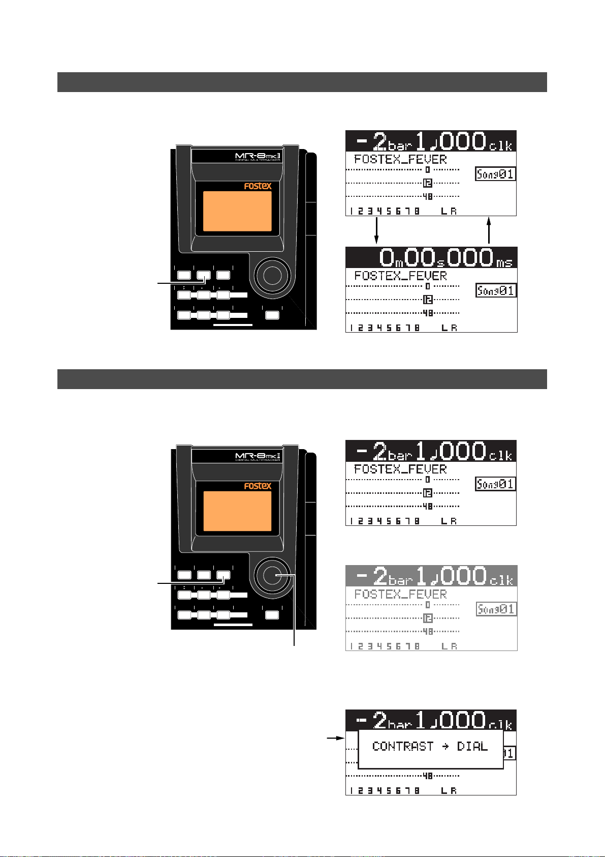
MR-8mkII Owner’s Manual (Names and functions)
Selecting a time base mode
When the display shows the home screen, pressing the [TIME BASE SELECT] key switches the time base
mode between Time and bar/beat.
Example of bar/beat display
RHYTHM
TIME BASE
CONTRAST
SELECT
STEREO
NEW
7/8
1-8
WAV FILE
SONG
BOUNCE
GHI3DEF2ABC1
BRIGHTNATURALPOWERFUL
MNO5JKL4
MASTERING
LOCATE
MENU/ENTER
[TIME BASE SELECT] key
GUIDE
1-4
5/6
1-6
7/8
Example of Time display
Adjusting the display contrast
You can adjust the display contrast by rotating the JOG dial while holding down the [CONTRAST] key.
Rotating the dial clockwise heightens the contrast, while rotating it counterclockwise lowers the contrast.
High contrast
RHYTHM
TIME BASE
CONTRAST
SELECT
STEREO
NEW
7/8
1-8
WAV FILE
SONG
BOUNCE
GHI3DEF2ABC1
BRIGHTNATURALPOWERFUL
MNO5JKL4
MASTERING
LOCATE
MENU/ENTER
[CONTRAST] key
GUIDE
5/6
1-4
7/8
1-6
JOG dial
Low contrast
While pressing down the [CONTRAST] key, the display shows "CONTRAST -> DIAL".
32
Page 33
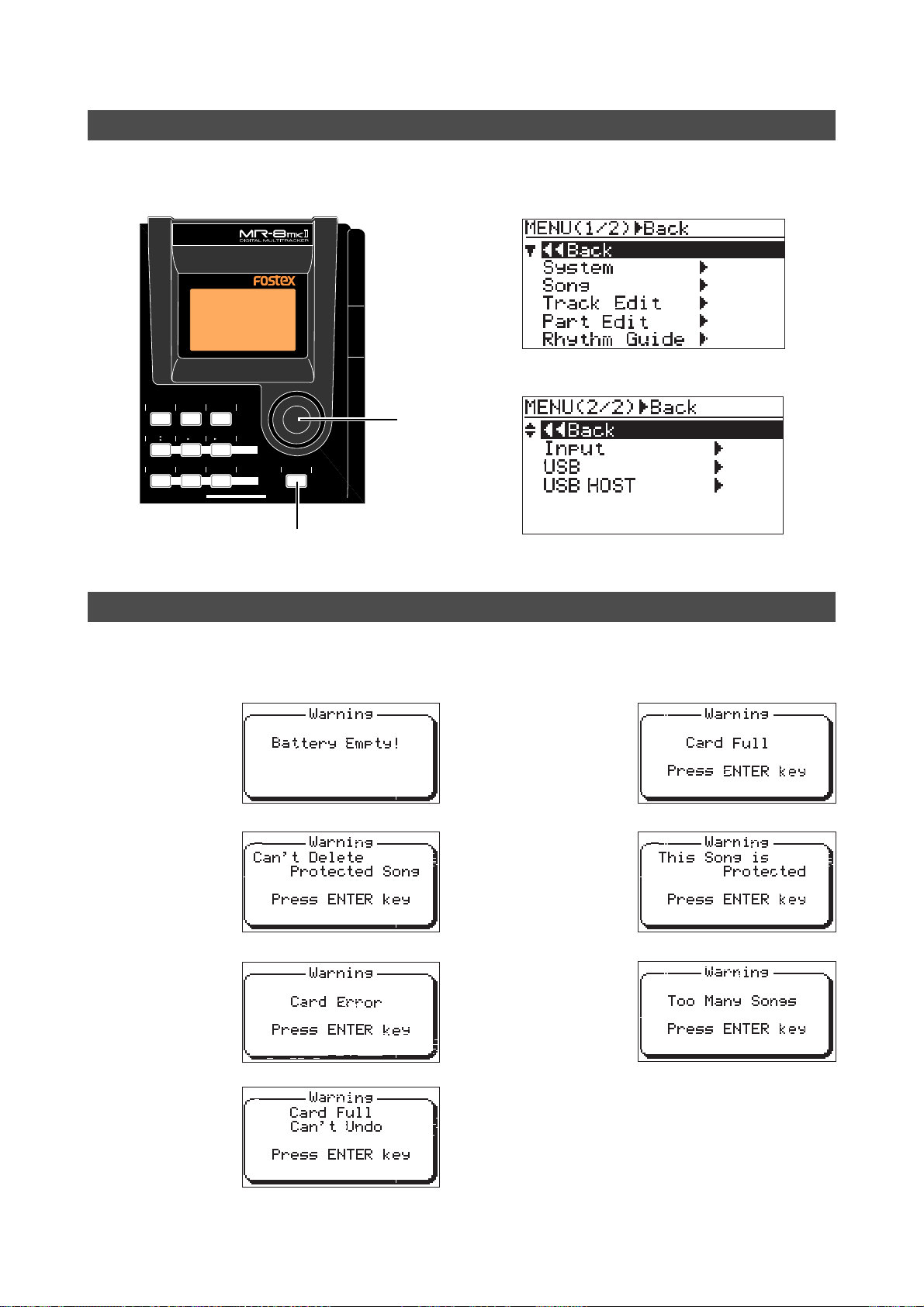
MR-8mkII Owner’s Manual (Names and functions)
MENU mode screen
Pressing the [MENU/ENTER] key while the recorder is stopped enters the menu mode and brings up the
menu screen. In the menu mode, you can make setting or editing via the appropriate screen. The top menu
screen has two pages, in which you can select the desired menu by rotating the JOG dial.
First page
RHYTHM
TIME BASE
GUIDE
5/6
1-4
7/8
1-6
CONTRAST
SELECT
JOG dial
STEREO
NEW
7/8
1-8
WAV FILE
SONG
BOUNCE
GHI3DEF2ABC1
BRIGHTNATURALPOWERFUL
MNO5JKL4
MASTERING
LOCATE
MENU/ENTER
[MENU/ENTER] key
Second page
Warning message
If a serious problem happens to the MR-8mkII during operation, an appropriate warning message is shown
on the display. Most warning messages are being shown until the [MENU/ENTER] key is pressed. Note that
there are also not-so-serious warning messages besides the following.
During recording, this
This message is
shown when the battery power is too low to
drive the MR-8mkII.
This message is
shown when you are
going to delete a song
which is protected.
This message is
shown when the MR8mkII cannot read a
card.
message is shown if
there is no more space
left on the card for continuing recording.
This message is shown
when you are going to
make recording or editing to a song which is
protected.
This message is shown
when you are going to
create a new song
while 99 songs exist on
the card.
This message is shown
when you are going to
edit a track or part operation but there is not
enough space on the
card for executing the
undo function.
33
Page 34

MR-8mkII Owner’s Manual (Names and functions)
34
Page 35

MR-8mkII Owner’s Manual (Basic recording operations)
Basic recording operations
This chapter describes basic multitrack recording.
If it is the first time for you to use a Multitracker, read this chapter
carefully first so that you are familiar with the MR-8mkII basic operations, then read other sections which describe advanced operations.
35
Page 36
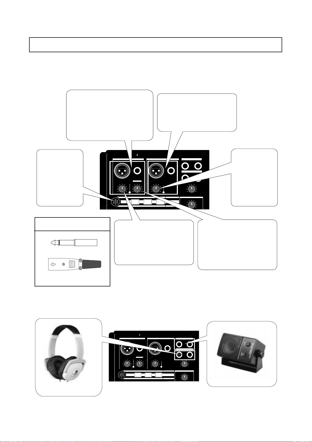
MR-8mkII Owner’s Manual (Basic recording operations)
Input connection
The MR-8mkII provides two input channels ([INPUT A] and [INPUT B]), which can connect a
microphone or line-level source (such as a keyboard). In addition, the [INPUT A] channel also
can accept an electric guitar as well as the internal microphone. The balanced (XLR) connector
can supply the phantom power for a condenser microphone (see page 137).
[INPUT A] channel
Both the [BAL] XLR connector and [UNBAL/
GUITAR] phone jack are provided. If you connect sources to both the XLR connector and
PHONE jack, the phone jack takes priority. If you
want to connect an electric guitar, connect it to
the phone jack and set the [INPUT A SELECT]
switch appropriately (see the next page).
Internal microphone
You can use the internal microphone by setting the [INPUT A SELECT] switch to "INT
MIC". In this condition,
you cannot use the [INPUT A] connectors.
Connectors which can be connected
to the MR-8mkII
Phone plug
[INPUT B] channel
Both the [BAL] XLR connector and [UNBAL/
GUITAR] phone jack are provided. Y ou cannot use both at a time. If you connect sources
to both the XLR connector and PHONE jack,
the phone jack takes priority.
INPUT A SELECT
INPUT A INPUT B
UNBAL
/GUITAR
BAL
GUITAR
DISTORTION
PEAK
TRIM
LINE
MIN
MIC
MAX
MIC
BRIT STACK US METAL 60'S COMBO
BAL
TRIM
PEAK
LINE
MIC
MIC SIMULATION
TUBECONDENSERDYNAMIC
AMP SIMULATION
UNBAL
INPUT A
L
1
REVERB/DELAY TIME
[TRIM] control
Controls the input gain (recording level) of
the [INPUT A] channel (including the internal microphone). Adjust the [TRIM] control
properly so that the PEAK indicator does not
blink or light at the loudest part of the input
signal (see page 15).
ST OUT
PHONES
PHONES VOL
MIN
EFFECT
R
2
MAX
Controls the input gain
(recording level) of the
[INPUT B] channel. Adjust the [TRIM] control
properly so that the PEAK
indicator does not blink or
light at the loudest part of
the input signal (see page
15).
[DISTORTION] contr ol
Y ou can record a distorted guitar sound to
the MR-8mkII. This control adjusts the
amount of the distortion effect for a guitar
connected to the phone jack on the [INPUT
A] channel. This control is effective only when
the [INPUT A SELECT] switch is set to "GUITAR".
[TRIM] control
XLR-3-12C type connector
You can connect headphones to the [PHONES] jacks (you can connect two pairs of headphones at a time) and/or powered monitors to the [STEREO OUT] jacks, as shown below.
INPUT A SELECT
INPUT A INPUT B
UNBAL
/GUITAR
BAL
GUITAR
DISTORTION
PEAK
TRIM
LINE
MIN
MIC
MAX
MIC
BRIT STACK US METAL 60'S COMBO
BAL
TRIM
PEAK
LINE
MIC
MIC SIMULATION
TUBECONDENSERDYNAMIC
AMP SIMULATION
UNBAL
INPUT A
ST OUT
L
PHONES
1
PHONES VOL
MAX
MIN
EFFECT
REVERB/DELAY TIME
R
2
Powered monitor
Headphones
36
Page 37
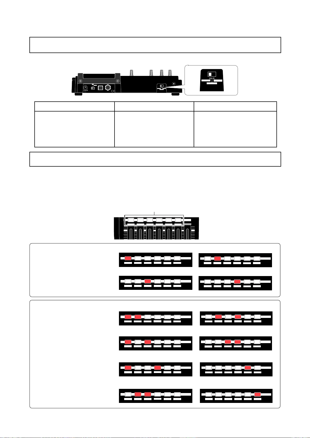
MR-8mkII Owner’s Manual (Basic recording operations)
About the [INPUT A SELECT] switch
When you use the [INPUT A] channel, the [INPUT A SELECT] switch must be set appropriately.
MIC/LINE
INT MIC
DC IN
OFF
12V
ON
LIGHT
POWER USB FOOT SW
INT MIC
INPUT A SELECT
MIC/LINE
GUITAR
GUITAR
INPUT A SELECT
“MIC/LINE” position
Set the switch to this position when the
source is an external microphone or line
level source connected to the [BAL] XLR
connector or [UNBAL/GUITAR] phone jack.
You can use the mic simulation insert effects (see page 60).
Set the switch to this position when the
source is a guitar connected to the [BAL]
XLR connector or [UNBAL/GUITAR]
phone jack. You can use the internal distortion effects, as well as the amplifier simulation insert effects (see page 60).
“GUIT AR ” position
“INT MIC” position
Set the switch to this position when the
source is the built-in microphone.
Y ou cannot use any insert effects. The [BAL]
XLR connector and [UNBAL/GUITAR] phone
jack are disabled.
Selectable recor ding tracks
You can record audio to one or two tracks simultaneously. Basically, tracks 1 through 4 are used for
recording mono sources, while tracks 5-6 and 7-8 are for recording stereo sources. The recording
tracks can be selected by the [REC SELECT] keys. When you select a single track, a signal fed to the
[INPUT A] channel (including the internal microphone) is recorded. When you select two tracks, each
source signal of the [INPUT A] and [INPUT B] channels is recorded to each selected track.
[REC SELECT] key
REC SELECT
MAX
Track 2
REC SELECT
7/8
REC SELECT
7/8
2 3
1
2 3
1
4
4
REC SELECT
7/8
5/6
REC SELECT
7/8
5/6
<Selectable single tracks>
When you record audio to a single
track, only the [INPUT A] channel is
available (including the internal microphone). Y ou cannot use the [INPUT B]
channel.
1 2 3 4 5/6 7/8 MASTER
MAX
Track 1
2 3
1
4
5/6
Track 3 Track 4
2 3
1
4
5/6
<Simultaneously selectable tw o tracks>
When you record audio to two tracks
simultaneously, a source signal of the
[INPUT A] channel is recorded to the
smaller numbered track, while a
source of the [INPUT B] channel is
recorded to the larger numbered track.
For example, when you record signals
to tracks 5/6, the input signals are assigned as below.
[INPUT A] -> Trac k 5
[INPUT B] -> Trac k 6
Tracks 1 and 2
2 3
1
4
5/6
REC SELECT
7/8
Tracks 1 and 3
2 3
1
4
5/6
Tracks 1 and 4
2 3
1
4
5/6
Tracks 2 and 3
2 3
1
4
5/6
REC SELECT
7/8
Tracks 5 and 6 (selectable with a single key)
REC SELECT
7/8
Tracks 7 and 8 (selectable with a single key)
REC SELECT
7/8
1
1
1
1
Tracks 2 and 4
2 3
Tracks 3 and 4
2 3
2 3
2 3
4
5/6
4
5/6
4
5/6
4
5/6
REC SELECT
7/8
REC SELECT
7/8
REC SELECT
7/8
REC SELECT
7/8
37
Page 38
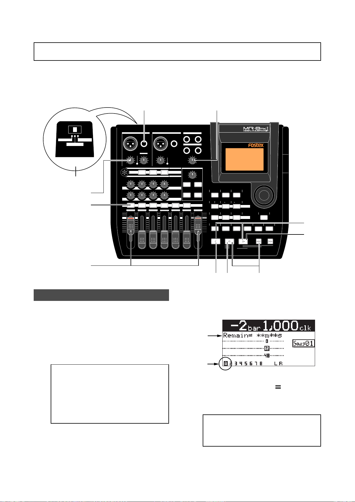
MR-8mkII Owner’s Manual (Basic recording operations)
Recording onto a single trac k
You can record onto any one of tracks 1 through 4. When making recording to a single track, you
can record a signal fed to the [INPUT A] channel.
The following describes the procedure for recording a guitar sound onto track 1. We assume that
a CompactFlashTM Card is set to the slot and Song01 is loaded.
INT MIC
GUITAR
INPUT A SELECT
2
MIC/LINE
6
3
4
1
INPUT A SELECT
INPUT A INPUT B
UNBAL
/GUITAR
BAL
GUITAR
DISTORTION
PEAK
TRIM
LINE
MIN
MIC
MAX
MIC
BRIT STACK US METAL 60'S COMBO
010
100100100
LR LR LR
RL
1 2 3 4 5/6 7/8 MASTER
MAX
MIN
UNBAL
BAL
TRIM
PEAK
LINE
MIC
MIC SIMULATION
TUBECONDENSERDYNAMIC
INPUT A
AMP SIMULATION
EFFECT SEND
PAN
ST OUT
L
PHONES
1
PHONES VOL
MAX
MIN
EFFECT
REVERB/DELAY TIME
MIN MAX
PLATE DELAY
REC SELECT
6
R
2
HALLROOM
RHYTHM
TIME BASE
GUIDE
1-4
1-6
MAX
AUTO PUNCH
MIN
PQR6
5
CONTRAST
SELECT
5/6
7/8
1-8
MNO5JKL4
PLAY MODE
NEW
SONG
LOCATE REC END
LOCATE ABS ZERO
A-B PLAY
STEREO
7/8
WAV FILE
GHI3DEF2ABC1
BRIGHTNATURALPOWERFUL
A / IN B / OUT
BOUNCE
MASTERING
LOCATE
PLAYSTOPRECORD REWIND F FWD
MENU/ENTER
STORE
UNDO/REDO
89
7
DELETE+-_0YZ9VWX8STU7
10
Preparation for recording
1) Connect a guitar to the [UNBAL/GUITAR] phone
jack of the [INPUT A] channel.
2) Set the [INPUT A SELECT] switch to "GUITAR".
When recording a guitar sound with the [INPUT A SELECT] switch set to “GUITAR”, you can
use the amplifier simulation effect (see page
60).
<Note>:
or line output signal such as a keyboard
output, set the [INPUT A SELECT] switch to
“MIC/LINE”. To record a built-in microphone sound, set the [INPUT A SELECT]
switch to “INT MIC”. When setting the switch
to “MIC/LINE”, you can use the microphone
simulation effect (see page 60).
3) Press the [REC SELECT] key for track 1.
Track 1 is record armed and the [REC SELECT]
key for track 1 starts flashing.
On the home screen, the remaining time is
shown, while "1" for the track number changes
to "A".
To record an external microphone
This indicates that the [INPUT A] channel is
assigned to track 1 and you can now record
the source (guitar) connected to the [INPUT A]
channel.
4) Set track fader 1 and [MASTER] fader to the
nominal position (marked by
).
Raising these faders allows you to monitor the
input sound. If these faders are not raised, you
cannot monitor the sound via headphones.
<Note>:
The fader for track 1 is used to adjust the monitor level. To adjust the recording level, use the [TRIM] control of the [INPUT A] channel.
38
Page 39
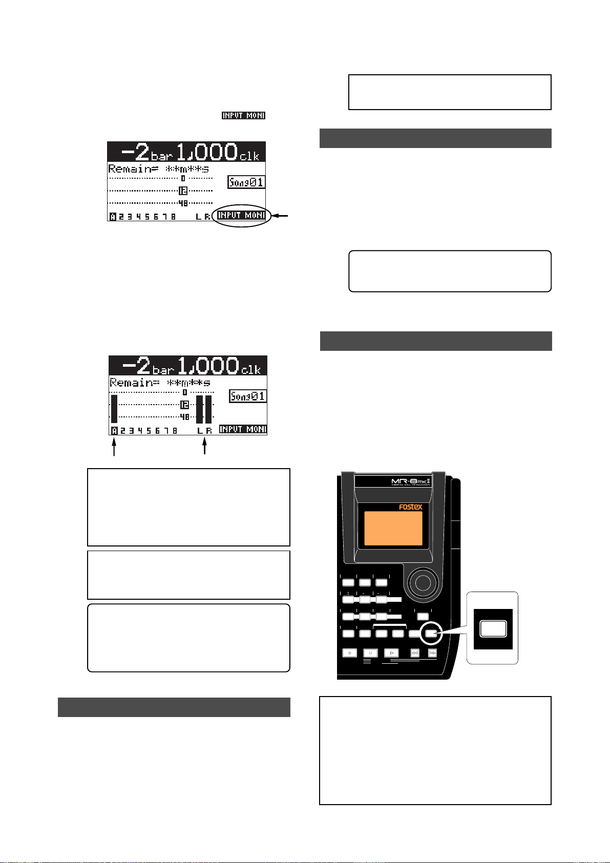
MR-8mkII Owner’s Manual (Basic recording operations)
5) Press the [RECORD] key once (the key indicator
starts flashing).
Track 1 (which is record armed) now enters
the input monitor mode and "
" is
shown on the home screen.
6) While playing the guitar, adjust the recording level
using the [TRIM] control of the [INPUT A]
channel.
Adjust the level appropriately so that the PEAK
indicator does not light.
Turning the [PHONES VOL] control clockwise
raises the headphone monitor level.
The screen shows the input level of track 1, as
well as the stereo L and R output levels.
<Note>:
We recommend to press the [REC
SELECT] key for track 1 to unarm track 1.
Playing back the recor ded trac k
9) Press the [REWIND] key while holding down the
[STOP] key to locate the recor der to the
beginning of the song.
10) Press the [PLAY] key to start playback.
You can adjust the monitor level using the track
1 fader, as well as the [MASTER] fader and
[PHONES VOL] control.
<Tip>: If you are not satisfied with the re-
sult, use the undo/redo function to cancel
the recording and try again.
Undoing recording (undo/redo)
If you press the [UNDO/REDO] key after finishing
recording, you can return to the condition before
the recording started (UNDO operation). Therefore,
you can try recording again.
<Note>:
Adjust the [TRIM] control properly
so that the PEAK indicator does not light at
the loudest part of the guitar sound. If the
input level is too high, the PEAK indicator
lights and the sound may be distorted or
noisy.
<Note>:
When you do not use the distortion
effects, turn down the [DISTORTION] control fully counterclockwise.
<Tip>: When receiving a line level signal, set
the [TRIM] control to left ("LINE") to get the
appropriate level. When receiving a microphone signal, set the [TRIM] control to right
("MIC") to get the appropriate level.
Starting recording
7) While holding down the [RECORD] key , press the
[PLAY] key to start recording.
The guitar is recorded.
8) When recording completes, press the [ST OP] key
to stop the recorder .
If you press the [UNDO/REDO] key again (after
UNDO), the undo operation is canceled and you
can return to the condition when the recording
finished (REDO operation).
RHYTHM
TIME BASE
CONTRAST
GUIDE
SELECT
1-4
5/6
STEREO
NEW
7/8
1-8
1-6
7/8
WAV FILE
SONG
BOUNCE
AUTO PUNCH
PQR6
MNO5JKL4
PLAY MODE
GHI3DEF2ABC1
BRIGHTNATURALPOWERFUL
A / IN B / OUT
LOCATE REC END
LOCATE ABS ZERO
A-B PLAY
LOCATE
MENU/ENTER
MASTERING
STORE
PLAYSTOPRECORD REWIND F FWD
UNDO/REDO
DELETE+-_0YZ9VWX8STU7
UNDO/REDO
DELETE
[UNDO/REDO] key
<Notes>:
The undo/redo function is available for
all kind of recordings, however, if you carry out
any of the following operations after making recording, you cannot undo the recording.
• Carrying out new recording.
• Carrying out track or part editing.
• Turning off the power.
• Selecting another song or editing the song name.
39
Page 40
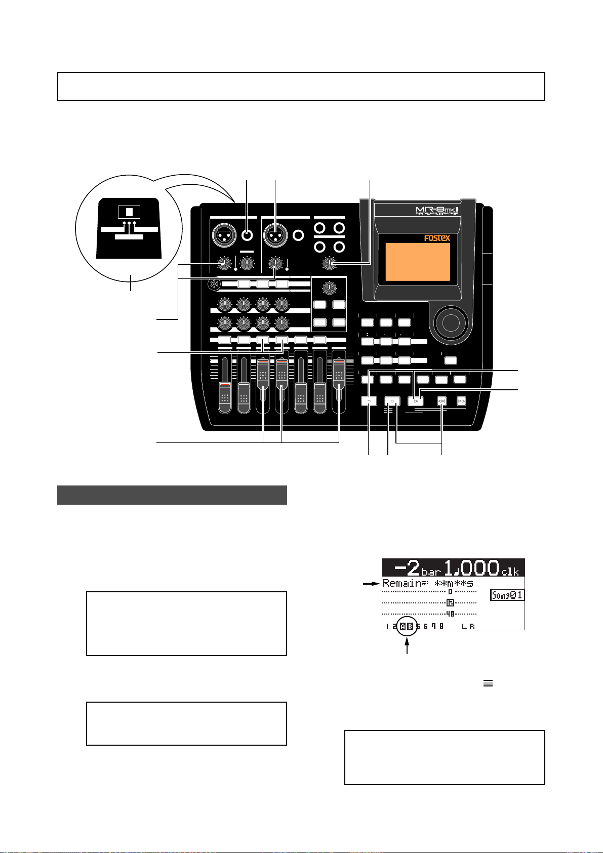
MR-8mkII Owner’s Manual (Basic recording operations)
Recording onto tw o tracks sim ultaneously
You can simultaneously record up to two tracks. See page 37 for the available combinations of
two recording tracks. The following describes the procedure for recording different sound sources
simultaneously to tracks 3 and 4. You can make two-track simultaneous recording with any
available track combination in the same manner.
INT MIC
MIC/LINE
GUITAR
INPUT A SELECT
2
6
4
3
1
1
INPUT A SELECT
INPUT A INPUT B
UNBAL
/GUITAR
BAL
GUITAR
DISTORTION
PEAK
TRIM
LINE
MIN
MIC
MAX
MIC
BRIT STACK US METAL 60'S COMBO
010
100100100
RL
LR LR LR
1 2 3 4 5/6 7/8 MASTER
MAX
MIN
UNBAL
BAL
TRIM
PEAK
LINE
MIC
MIC SIMULATION
TUBECONDENSERDYNAMIC
INPUT A
AMP SIMULATION
EFFECT SEND
PAN
ST OUT
L
PHONES
1
PHONES VOL
MAX
MIN
EFFECT
REVERB/DELAY TIME
MIN MAX
PLATE DELAY
REC SELECT
6
R
2
HALLROOM
RHYTHM
TIME BASE
GUIDE
1-4
1-6
MAX
AUTO PUNCH
MIN
PQR6
5
CONTRAST
SELECT
5/6
7/8
1-8
MNO5JKL4
PLAY MODE
NEW
SONG
LOCATE REC END
LOCATE ABS ZERO
A-B PLAY
STEREO
7/8
WAV FILE
GHI3DEF2ABC1
BRIGHTNATURALPOWERFUL
A / IN B / OUT
BOUNCE
MASTERING
LOCATE
PLAYSTOPRECORD REWIND F FWD
MENU/ENTER
STORE
UNDO/REDO
89
7
DELETE+-_0YZ9VWX8STU7
10
Preparation for recording
1) Connect the following sound sources to the
[UNBAL/GUITAR] phone jack of the [INPUT A]
channel and [BAL] XLR connector of the
[INPUT B] channels.
[INPUT A] -> Electric guitar
[INPUT B] -> Microphone (vocal)
<Note>:
phone to the [BAL] XLR connector of the [INPUT B] channel, you can supply the phantom power to the microphone (see page
137).
2) Set the [INPUT A SELECT] switch to "GUITAR".
You can add distortion of the internal effects
to your guitar sound.
<Note>:
as insert effects when the [INPUT A SELECT]
switch is set to "GUITAR" (see page 60).
3) Press the [REC SELECT] key for tracks 3 and 4.
Tracks 3 and 4 are record armed and the [REC
SELECT] keys for tracks 3 and 4 start flashing.
If you connect a condenser micro-
You can apply the amp simulation
On the home screen, track numbers "3" and
"4" changes to "A" and "B" respectively, showing that each input is assigned to the appropriate track.
The remaining time of the CompactFlash
Card is shown.
4) Set the track faders 3, 4 and [MASTER] fader to
the nominal position (marked by
).
Raising these faders allows you to monitor the
input sound. If these faders are not raised, you
cannot monitor the sound via headphones.
<Note>:
Track faders 3 and 4 are used to
adjust the monitor levels. To adjust the recording level, use the [TRIM] controls for
[INPUT A] and [INPUT B].
TM
40
Page 41
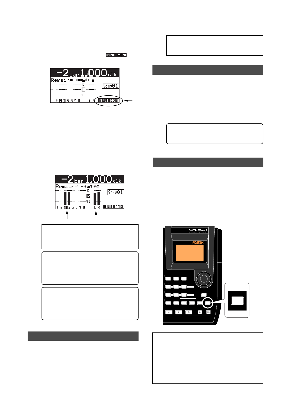
MR-8mkII Owner’s Manual (Basic recording operations)
5) Press the [RECORD] key once (the key indicator
starts flashing).
Tracks 3 and 4 (which are armed) now enter
the input monitor mode and "
" is
shown on the home screen.
6) While playing the music, adjust the recording
level of each track using the [TRIM] control of
each input channel.
Adjust the level appropriately so that the PEAK
indicator does not light.
Turning the [PHONES VOL] control clockwise
raises the headphone monitor level.
The screen shows the input level of tracks 3
and 4, as well as the stereo L and R output
levels.
<Note>:
We recommend to press the [REC
SELECT] key for tracks 3 and 4 to unarm
these tracks.
Playing back the recor ded trac k
9) Press the [REWIND] key while holding down the
[STOP] key to locate the recor der to the
beginning of the song.
10) Press the [PLAY] key to start playback.
You can adjust the monitor level using track
faders 3 and 4, as well as the [MASTER] fader
and [PHONES VOL] control.
<Tip>: If you are not satisfied with the re-
sult, use the undo/redo function to cancel
the recording and try again.
Undoing recording (undo/redo)
If you press the [UNDO/REDO] key after finishing
recording, you can return to the condition before
the recording started (UNDO operation). Therefore,
you can try recording again.
<Note>:
Adjust the [TRIM] control of each
input channel properly so that the PEAK
indicator does not light at the loudest part
of the sound.
<Tip>: You can add distortion to an electric
guitar connected to [INPUT A]. Use the [DISTORTION] control to adjust the distortion
level. When you add distortion, readjust the
[TRIM] control.
<Tip>: When receiving a line level signal, set
the [TRIM] control to left ("LINE") to get the
appropriate level. When receiving a microphone signal, set the [TRIM] control to right
("MIC") to get the appropriate level.
Starting recording
7) While holding down the [RECORD] key , press the
[PLAY] key to start recording.
The recorder starts recording.
8) When recording completes, press the [ST OP] key
to stop the recorder .
If you press the [UNDO/REDO] key again (after
UNDO), the undo operation is canceled and you
can return to the condition when the recording
finished (REDO operation).
RHYTHM
TIME BASE
CONTRAST
GUIDE
SELECT
1-4
5/6
STEREO
NEW
7/8
1-8
1-6
7/8
WAV FILE
SONG
BOUNCE
AUTO PUNCH
PQR6
MNO5JKL4
PLAY MODE
GHI3DEF2ABC1
BRIGHTNATURALPOWERFUL
A / IN B / OUT
LOCATE REC END
LOCATE ABS ZERO
A-B PLAY
MENU/ENTER
MASTERING
LOCATE
STORE
PLAYSTOPRECORD REWIND F FWD
UNDO/REDO
DELETE+-_0YZ9VWX8STU7
UNDO/REDO
DELETE
[UNDO/REDO] key
<Notes>:
The undo/redo function is available for
all kind of recordings, however, if you carry out
any of the following operations after making recording, you cannot undo the recording.
• Carrying out new recording.
• Carrying out track or part editing.
• Turning off the power.
• Selecting another song or editing the song name.
41
Page 42
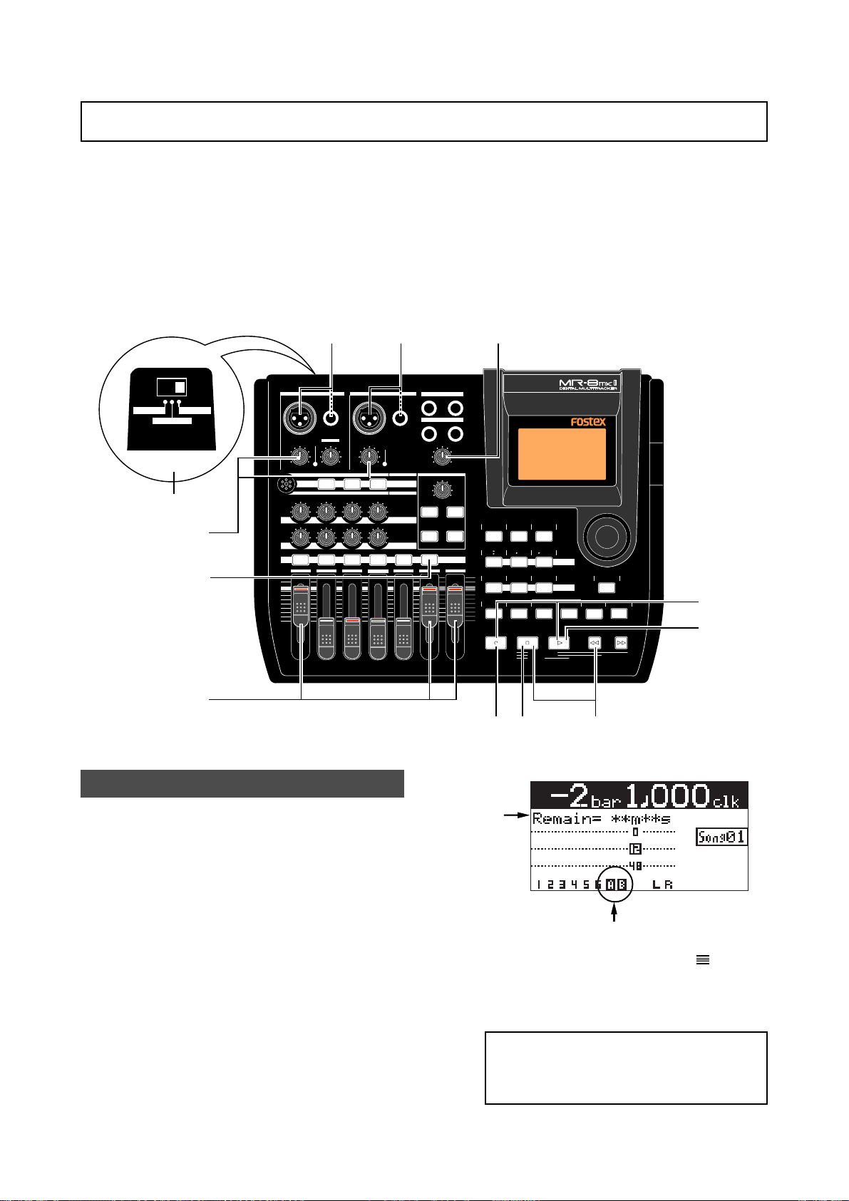
MR-8mkII Owner’s Manual (Basic recording operations)
Overdubbing basics
Overdubbing is recording something new while listening to the previously recorded track(s).
It is a very important method in multitrack recording. The following describes an example of
overdubbing for recording a stereo keyboard to tracks 7/8 while listening to the guitar on track
1. See the procedure previously described in "Recording onto a single track" for details about
how to record a guitar on track 1. In the procedure below, we assume that the song of which the
guitar has been recorded on track 1 is loaded.
Note that you can make overdubbing to another track or other tracks in the same manner as
described below.
MIC/LINE
INT MIC
GUITAR
INPUT A SELECT
2
4
7
3
1
INPUT A SELECT
INPUT A INPUT B
UNBAL
/GUITAR
BAL
GUITAR
DISTORTION
PEAK
TRIM
LINE
MIN
MIC
MAX
MIC
BRIT STACK US METAL 60'S COMBO
100100100
010
LR LR LR
RL
1 2 3 4 5/6 7/8 MASTER
MAX
MIN
1
UNBAL
BAL
TRIM
PEAK
LINE
MIC
MIC SIMULATION
TUBECONDENSERDYNAMIC
INPUT A
AMP SIMULATION
EFFECT SEND
PAN
ST OUT
L
PHONES
1
PHONES VOL
MAX
MIN
EFFECT
REVERB/DELAY TIME
MIN MAX
PLATE DELAY
REC SELECT
7
R
2
HALLROOM
RHYTHM
TIME BASE
5/6
7/8
CONTRAST
SELECT
NEW
7/8
1-8
SONG
MNO5JKL4
PLAY MODE
LOCATE REC END
LOCATE ABS ZERO
A-B PLAY
8,10
STEREO
WAV FILE
BOUNCE
GHI3DEF2ABC1
BRIGHTNATURALPOWERFUL
MASTERING
LOCATE
A / IN B / OUT
PLAYSTOPRECORD REWIND F FWD
6,12
STORE
MENU/ENTER
UNDO/REDO
DELETE+-_0YZ9VWX8STU7
9
6,12
GUIDE
1-4
1-6
MAX
AUTO PUNCH
MIN
PQR6
5
Preparation for recording
1) Connect the L and R outputs of the keyboard to
input connectors of the [INPUT A] and [INPUT B]
channels.
Connect the L and R outputs to the [INPUT A]
and [INPUT B] channels respectively.
2) Set the [INPUT A SEL] switch to "MIC/LINE".
3) Press the [REC SELECT] key for tracks 7/8.
Tracks 7/8 are record armed and the [REC SELECT] key for tracks 7/8 starts flashing.
On the home screen, the remaining time is
shown, while "7" and "8" for the track numbers change to "A" and "B" respectively.
This indicates you can now record the [INPUT
A] and [INPUT B] channel signals to tracks 7
and 8 respectively.
4) Set track faders 1 and 7/8 and the [MASTER] fader
to the nominal position (marked by
Raising these faders allows you to monitor the
input sound. If these faders are not raised, you
cannot monitor the sound via headphones.
<Note>:
Track 1 and 7/8 faders are used to
adjust the monitor level. To adjust the recording levels, use the [TRIM] controls of
the [INPUT A] and [INPUT B] channels.
42
).
Page 43
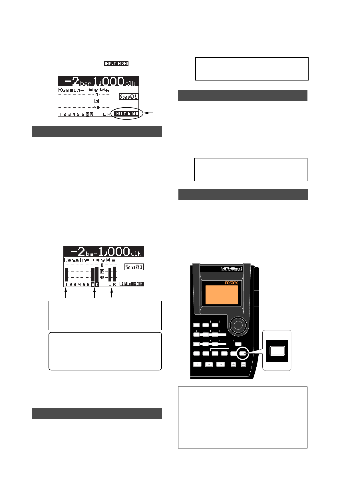
MR-8mkII Owner’s Manual (Basic recording operations)
5) Press the [RECORD] key once (the key indicator
starts flashing).
The armed tracks 7/8 now enter the input
monitor mode, while "
" is shown on
the home screen.
Adjusting the recording levels while listening to track 1
6) Press the [PLAY] key to play back the song fr om
the beginning.
Though tracks 7/8 are in the input monitor
mode, you can hear the track 1 signal by
rotating the [PHONES VOL] control clockwise
(while the meter for track 1 shows the
playback level).
7) While playing the keyboard, adjust the recording
levels using the [TRIM] controls of the [INPUT A]
and [INPUT B] channels.
Adjust the levels appropriately so that the PEAK
indicators for these input channels do not light.
The home screen shows the playback level of
track 1 and the input levels of tracks 7 and 8,
as well as the stereo L and R output levels.
10) When recording completes, press the [STOP] ke y
to stop the recorder.
<Note>:
We recommend to press the [REC
SELECT] key for tracks 7/8 to unarm tracks
7/8.
Playing back the recor ded trac k
11) Press the [REWIND] ke y while holding do wn the
[STOP] key to locate the recor der to the
beginning of the song.
12) Press the [PLAY] key to start playback.
You can adjust the monitor level using the track
faders, as well as the [MASTER] fader and
[PHONES VOL] control.
<Note>:
If you are not satisfied with the result, use the undo/redo function to cancel
the recording and try again.
Undoing recording (undo/redo)
If you press the [UNDO/REDO] key after finishing
recording, you can return to the condition before
the recording started (UNDO operation). Therefore,
you can try recording again.
If you press the [UNDO/REDO] key again (after
UNDO), the undo operation is canceled and you
can return to the condition when the recording
finished (REDO operation).
<Note>:
Adjust each [TRIM] control properly so that the corresponding PEAK indicator does not light at the loudest part of
the keyboard sound.
<Tip>: When receiving a line level signal, set
the [TRIM] control to left ("LINE") to get the
appropriate level. When receiving a microphone signal, set the [TRIM] control to right
("MIC") to get the appropriate level.
8) After adjusting the recording levels properly,
press the [REWIND] key while holding down the
[STOP] key to locate the recor der to the
beginning of the song.
Starting recording
9) While holding down the [RECORD] key , press the
[PLAY] key to start recording.
The recorder records the keyboard while
playing back track 1 (guitar).
43
RHYTHM
TIME BASE
CONTRAST
GUIDE
SELECT
1-4
5/6
STEREO
NEW
7/8
1-8
1-6
7/8
WAV FILE
SONG
BOUNCE
AUTO PUNCH
PQR6
MNO5JKL4
PLAY MODE
GHI3DEF2ABC1
BRIGHTNATURALPOWERFUL
A / IN B / OUT
LOCATE REC END
LOCATE ABS ZERO
A-B PLAY
MENU/ENTER
MASTERING
LOCATE
STORE
PLAYSTOPRECORD REWIND F FWD
UNDO/REDO
DELETE+-_0YZ9VWX8STU7
UNDO/REDO
DELETE
[UNDO/REDO] key
<Notes>:
The undo/redo function is available for
all kind of recordings, however, if you carry out
any of the following operations after making recording, you cannot undo the recording.
• Carrying out new recording.
• Carrying out track or part editing.
• Turning off the power.
• Selecting another song or editing the song name.
Page 44
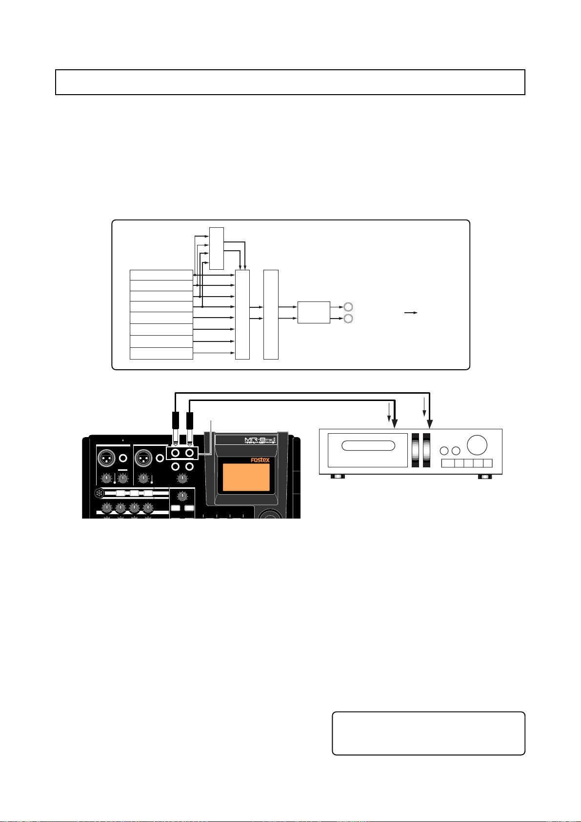
MR-8mkII Owner’s Manual (Basic recording operations)
Basic mixdown
This section describes basic mixdown which is the final process of multitrack recording. Mixdown
mixes recorded materials on tracks 1 through 8 down to Stereo L/R (two tracks) as shown in the
figure below. While playing back all tracks, you can apply effects (reverb/delay) to tracks 1
through 4 or adjust stereo panning and feed mixed-down signals to an external master recorder.
With the MR-8mkII, y ou can also record a mixed-do wn signal internally to a new song of the MR-8mkII using
the track bouncing function, without the need of an external master recorder (see "Track bouncing" described later).
Delay or Reverb
Track 1 (Playback)
Track 2 (Playback)
Track 3 (Playback)
Track 4 (Playback)
Track 5 (Playback)
Track 6 (Playback)
Track 7 (Playback)
Track 8 (Playback)
Mixing
Mastering effects
D/A
STEREO OUT (L)
STEREO OUT (R)
Analog signals
[STEREO OUT L, R]
MR-8mkII
INPUT A SELECT
INPUT A INPUT B
UNBAL
/GUITAR
BAL
GUITAR
DISTORTION
PEAK
TRIM
LINE
MIN
MIC
MAX
MIC
BRIT STACK US METAL 60'S COMBO
010
100100100
BAL
TRIM
LINE
MIC
TUBECONDENSERDYNAMIC
PEAK
UNBAL
MIC SIMULATION
INPUT A
AMP SIMULATION
EFFECT SEND
ST OUT
L
PHONES
1
PHONES VOL
MIN
EFFECT
REVERB/DELAY TIME
MIN MAX
PLATE DELAY
R
2
MAX
HALLROOM
RHYTHM
TIME BASE
CONTRAST
GUIDE
SELECT
1) Connect the [STEREO OUT (L, R)] connectors of
the MR-8mkII to the input connectors of an
analog master recorder .
2) While playing back the MR-8mkII, rehearse
mixing down the recorded sounds by adjusting
the level and panning of each track, applying
effects to tracks 1 through 4 and appl ying the
mastering effects to the L/R stereo mix, etc.
The output levels from the [STEREO OUT (L,
R)] connectors can be controlled by the
[MASTER] fader.
Adjust the levels appropriately so that the
highest segments of L and R meters do not light.
See "Using effects" on page 59 for details about
the delay/reverb and mastering effects.
Analog master recorder
3) Adjust the recording level of the master recorder
while rehearsing mixdown.
See the manual of the master recorder for
details about how to adjust the recording level.
4) After rehearsing mixdown and adjusting the
recording level, locate the MR-8mkII to the
beginning of the song.
5) Start the master recorder recording and then start
the MR-8mkII playing back.
6) After finishing recording, stop both recor ders.
<Tip>: By sliding up or down the MR-8mkII
[MASTER] fader gradually, you can fade in
or fade out recording.
44
Page 45

MR-8mkII Owner’s Manual (Advanced playback and locate functions)
Adv anced playbac k and locate functions
This chapter describes advanced playback functions including cueing, partial playback (between points A and B), special play modes,
as well as the locate function.
45
Page 46
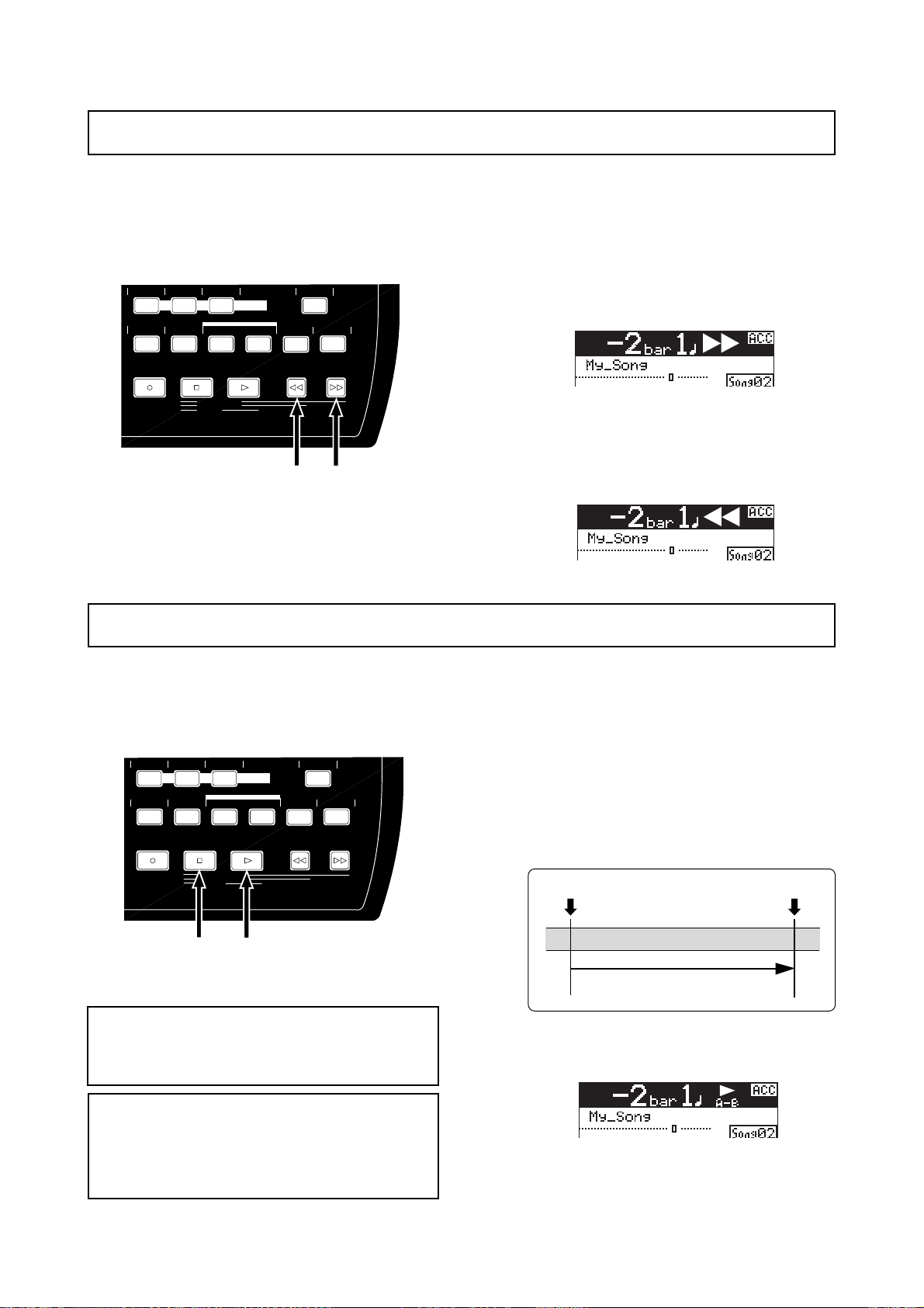
MR-8mkII Owner’s Manual (Advanced playback and locate functions)
3 x cueing
By holding down the [F FWD] or [REWIND] key during playback, the recorder enters cueing
mode and you can monitor playback at 3 x speed. It may be useful for searching a specific
position.
• By holding down the [F FWD] key during play
back, the recor der starts cueing forwards at 3 x
speed.
During forward cueing, ">>" is shown on the
display.
• By holding down the [REWIND] key during play
back, the recor der starts cueing bac kwar ds at 3
x speed.
During backward cueing, "<<" is shown on the
display.
AUTO PUNCH
PQR6
MNO5JKL4
PLAY MODE
BRIGHTNATURALPOWERFUL
MASTERING
LOCATE
A / IN B / OUT
PLAYSTOPRECORD REWIND F FWD
LOCATE REC END
LOCATE ABS ZERO
A-B PLAY
MENU/ENTER
STORE
[REWIND] key [F FWD] key
UNDO/REDO
DELETE+-_0YZ9VWX8STU7
Playbac k between LOCATE A and B points
When the LOCATE A and LOCATE B points are set, you can playback between these points once.
This function is always available regardless of the play mode setting (see "Play mode" on next
page). This function allows you to check the editing part (between LOCATE A and B points) for
copy/paste, erase, etc. See "Part editing" described later.
STORE
MENU/ENTER
UNDO/REDO
DELETE+-_0YZ9VWX8STU7
• While the recorder is stopped, press the [PLAY]
key while holding down the [ST OP] key.
The MR-8mkII plays back audio data between
the LOCATE A and LOCATE B points once, then
stops.
LOCATE A point
Playback
LOCATE B point
While the recorder is playing back between the
LOCATE A and B points, the display shows the
icon as below.
BRIGHTNATURALPOWERFUL
MASTERING
LOCATE
A / IN B / OUT
PLAYSTOPRECORD REWIND F FWD
LOCATE REC END
LOCATE ABS ZERO
A-B PLAY
[PLAY] key
AUTO PUNCH
PQR6
<Note>:
MNO5JKL4
PLAY MODE
[STOP] key
Note that this function is available only
when the LOCATE A and B points are set.
See page 51 for details about how to set the LOCATE A and B points.
<Note>:
If you carry out the operation above when
the LOCATE A point is set ahead of the LOCATE B
point (i.e. LOCATE A > LOCATE B), the MR-8mkII
plays back audio data from the LOCATE A point
to the REC END points once, then stops.
During playback, you can monitor playback
audio of the desired track(s) by raising the appropriate track fader(s), the [MASTER] fader
and the [PHONES] control.
46
Page 47
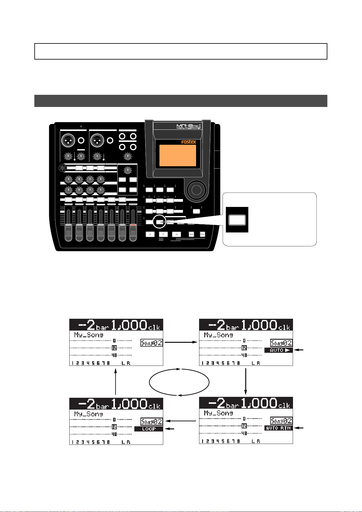
MR-8mkII Owner’s Manual (Advanced playback and locate functions)
Play mode
The MR-8mkII offers special play modes including the auto play, auto return and loop playback
modes in addition to the normal playback mode.
Selecting a play mode
INPUT A SELECT
INPUT A INPUT B
UNBAL
/GUITAR
BAL
DISTORTION
PEAK
TRIM
LINE
MIN
MIC
MIC
BRIT STACK US METAL 60'S COMBO
010
RL
LR LR LR
1 2 3 4 5/6 7/8 MASTER
MAX
MIN
BAL
GUITAR
TRIM
PEAK
LINE
MAX
MIC
TUBECONDENSERDYNAMIC
100100100
AMP SIMULATION
EFFECT SEND
UNBAL
MIC SIMULATION
INPUT A
PAN
ST OUT
L
PHONES
1
PHONES VOL
MAX
MIN
EFFECT
REVERB/DELAY TIME
MIN MAX
PLATE DELAY
REC SELECT
R
2
HALLROOM
RHYTHM
TIME BASE
GUIDE
1-4
1-6
MAX
AUTO PUNCH
MIN
PQR6
CONTRAST
SELECT
5/6
7/8
1-8
MNO5JKL4
PLAY MODE
NEW
SONG
STEREO
7/8
WAV FILE
GHI3DEF2ABC1
BRIGHTNATURALPOWERFUL
A / IN B / OUT
LOCATE REC END
LOCATE ABS ZERO
A-B PLAY
BOUNCE
MENU/ENTER
MASTERING
LOCATE
STORE
PLAYSTOPRECORD REWIND F FWD
UNDO/REDO
DELETE+-_0YZ9VWX8STU7
PLAY MODE
STU7
While the recorder is
stopped, you can choose
the desired play mode by
pressing the [PLAY
MODE] key as many
times as needed.
While the recorder is stopped, each time you press the [PLAY MODE] key, the play
mode switches among "Off", "Auto Play", "Auto return" and "Loop".
The current mode is shown on the screen as follows (when "Off" is selected, there is
no indication).
Play mode "off"
Lighting
Auto play mode
Lighting
Lighting
Loop mode
Auto return mode
47
Page 48
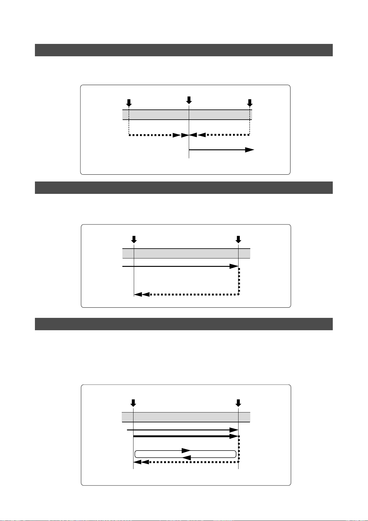
MR-8mkII Owner’s Manual (Advanced playback and locate functions)
Auto play mode
In the Auto play mode, when locating to the ABS ZERO, REC END, LOCATE A or LOCATE B point,
the recorder automatically starts playback from the point. The following shows the auto play
function after locating to the LOCATE A point (see page 50 for the locate function).
The point where you
execute the locate function
Locate
LOCATE A point
Playback
When locating to the LOCATE A point,
the recorder automatically starts
playback immediately.
The point where you
execute the locate function
Locate
Auto return mode
The auto return mode is active when the LOCATE A and LOCATE B points are set.
In the auto return mode, when reaching at the LOCATE B point during playback, the recorder
automatically locates to the LOCATE A point and stops.
LOCATE A point
playback
LOCATE B point
When reaching at the LOCATE B point during playback,
the recorder automatically locates to the LOCATE A
point and stops.
Loop mode
As with the auto return mode, the loop mode is active when the LOCATE A and LOCATE B points
are set. In the loop mode, when reaching at the LOCATE B point during playback, the recorder
automatically locates to the LOCATE A point and starts playback. The recorder repeats this
behavior until you stop the recorder.
You may find it very convenience to use the loop function together with the auto punch in/out
function (see the next page).
LOCATE A point
Playback
When locating to the LOCATE A point, the recorder
automatically starts playback.
LOCATE B point
When reaching at the LOCATE B point during
playback, the recorder automatically locates to
the LOCATE A point.
48
Page 49
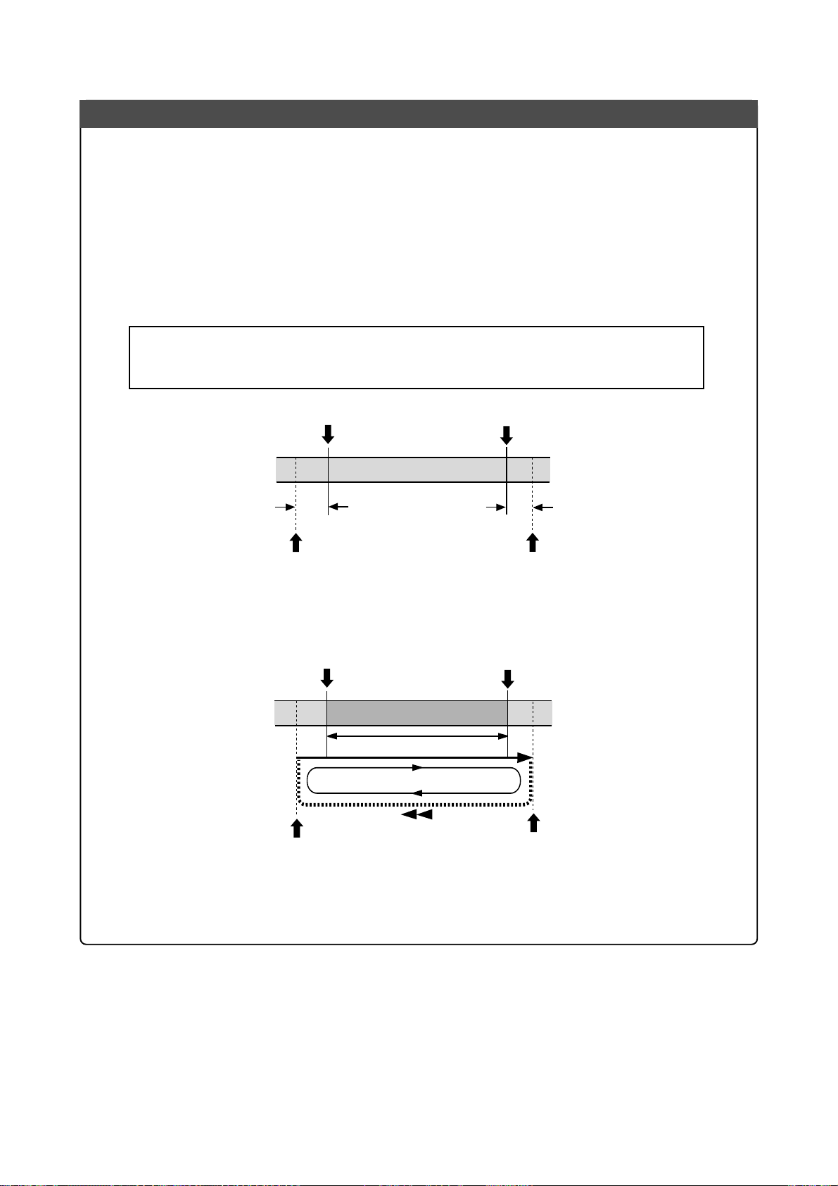
MR-8mkII Owner’s Manual (Advanced playback and locate functions)
Loop function in auto punch in/out mode
When the loop mode is active (while the auto punch in/out mode is inactive), the LOCATE
A and LOCATE B points are used as the loop start and end points. When the auto punch in/
out mode is active (while the loop mode is inactive), the LOCATE A and LOCATE B points
are used as the punch-in and punch-out points.
When both the auto punch in/out and loop modes are active, the LOCATE A and LOCATE
B points are used as the punch-in and punch-out points, while the loop function starts at
"the LOCATE A point minus the pre-roll time" and ends at "the LOCATE B point plus the
post-roll time, as shown below. The pre-roll time is initially set to four seconds, while the
post-roll time is set to one second.
<Note>:
LOCATE B point to the recording end point (REC END) of a song, the pre-roll or post-roll
time is ignored.
If you set the LOCATE A point to the beginning of a song (ABS ZERO) or set the
LOCATE A point
4 sec.
LOOP START point
LOCATE B point
1 sec.
LOOP END point
Using the loop function in the auto punch in/out mode reduces the number of key presses,
allowing you to concentrate on playing.
LOCATE A point
(Punch in point)
LOCATE B point
(Punch out point)
LOOP START point
LOOP END point
You can change the pre-roll and post-roll time within the range between 0.1 and 10.0
seconds (in 0.1 second steps) in the menu mode (see page 134).
49
Page 50
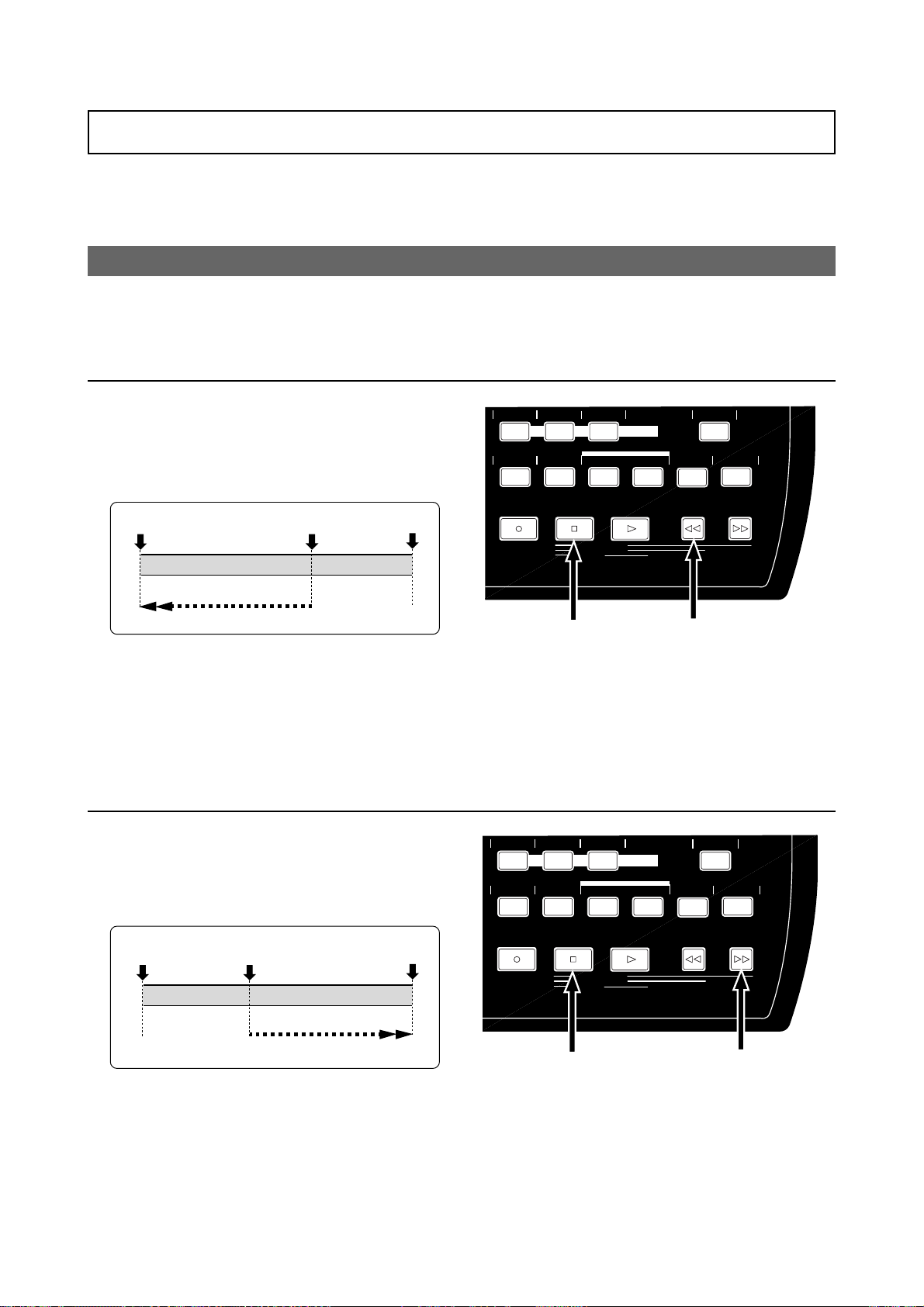
MR-8mkII Owner’s Manual (Advanced playback and locate functions)
Locate function
The following describes the locate functions, which allow you to immediately skip to a specified
point in a song.
Time locate
Regardless of the current recorder position, you can locate to the beginning (ABS ZERO) of the
song or the recording end (REC END) of the song.
Locating to the beginning (ABS ZERO) of a song
• While the recorder is stopped, press the
[REWIND] key while holding down the [ST OP] key .
The MR-8mkII immediately locates to the
beginning of the song (ABS ZERO) and stops.
ABS ZERO
The current position
Locate
REC END
AUTO PUNCH
PQR6
MNO5JKL4
PLAY MODE
Locating to the recording end point (REC END) of a song
• While the recorder is stopped, press the [F FWD]
key while holding down the [ST OP] key.
MNO5JKL4
The MR-8mkII immediately locates to the
recording end of the song (REC END) and stops.
ABS ZERO
The current position
REC END
AUTO PUNCH
PLAY MODE
PQR6
BRIGHTNATURALPOWERFUL
A / IN B / OUT
LOCATE REC END
LOCATE ABS ZERO
A-B PLAY
MASTERING
LOCATE
PLAYSTOPRECORD REWIND F FWD
MENU/ENTER
STORE
Press the [REWIND] key while
holding down the [STOP] key.
BRIGHTNATURALPOWERFUL
A / IN B / OUT
LOCATE REC END
LOCATE ABS ZERO
A-B PLAY
MASTERING
LOCATE
PLAYST OPRECORD REWIND F FWD
MENU/ENTER
STORE
UNDO/REDO
DELETE+-_0YZ9VWX8STU7
UNDO/REDO
DELETE+-_0YZ9VWX8STU7
Locate
Press the [F FWD] key while
holding down the [STOP] key.
50
Page 51
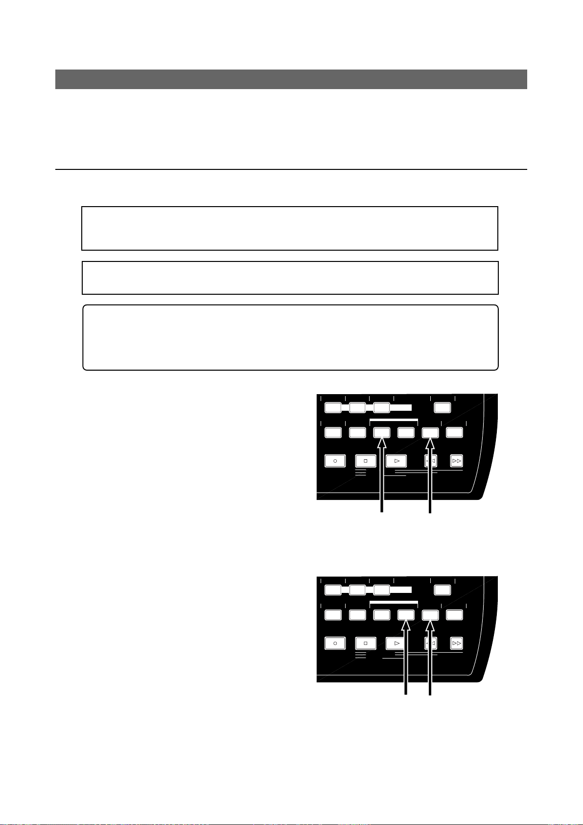
MR-8mkII Owner’s Manual (Advanced playback and locate functions)
Locating to the LOCATE A or LOCATE B point
You can set the desired point of a song as the LOCATE A or LOCATE B point.
The LOCATE A and B points can be used not only for locating, but also for auto punch in/out,
play modes and part editing, etc.
Setting the LOCATE A or LOCATE B point
You can set the LOCATE A or LOCATE B point while the recorder is running or stops at the
desired point, regardless of time base setting.
<Note>:
You cannot set the LOCATE A or B point for a protected song. If you are going to do so,
the warning message ("This song is protected!") is shown. To set the LOCATE A or B point for a
protected song, release the protection first (see page 93).
<Note>:
The LOCATE A point must be earlier than the LOCATE B point. If not, you cannot carry
out the auto punch in/out or loop function correctly.
<Tip>: While the time base is set to the bar/beat mode, if you set the "Beat resolution" menu
item in the menu mode to "On", you can store the LOCATE A or B point in beat resolution. In
other words, the clock digit of the Bar/Beat/Clk value is automatically rounded down or up, so
that the clock digit is always "000".
See page 136 for details about how to make the beat resolution active or inactive.
STORE
MENU/ENTER
UNDO/REDO
DELETE+-_0YZ9VWX8STU7
• To set the LOCATE A point:
When the recorder is playing back (or stopped),
press the [LOCATE A/IN] key at the desired point
while holding down the [STORE] key.
The display briefly shows "Store LOCATE A",
and the point when pressing the [LOCATE A/IN]
key is stored as the LOCATE A point.
AUTO PUNCH
PQR6
MNO5JKL4
PLAY MODE
BRIGHTNATURALPOWERFUL
MASTERING
LOCATE
A / IN B / OUT
PLAYSTOPRECORD REWIND F FWD
LOCATE REC END
LOCATE ABS ZERO
A-B PLAY
• To set the LOCATE B point:
When the recorder is playing back (or stopped),
press the [LOCATE B/OUT] key at the desired
point while holding down the [STORE] ke y.
The display briefly shows "Store LOCATE B", and
the point when pressing the [LOCATE B/OUT]
key is stored as the LOCATE B point.
51
Press the [LOCATE A/IN] key while
holding down the [STORE] key .
BRIGHTNATURALPOWERFUL
MASTERING
LOCATE
A / IN B / OUT
PLAYSTOPRECORD REWIND F FWD
LOCATE REC END
LOCATE ABS ZERO
A-B PLAY
AUTO PUNCH
PQR6
MNO5JKL4
PLAY MODE
Press the [LOCATE B/OUT] key while
holding down the [STORE] key .
STORE
MENU/ENTER
UNDO/REDO
DELETE+-_0YZ9VWX8STU7
Page 52
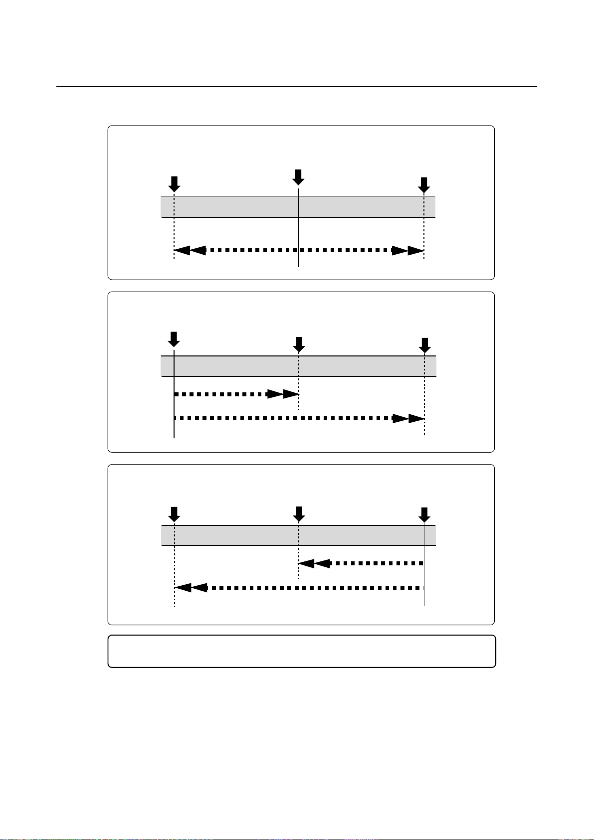
MR-8mkII Owner’s Manual (Advanced playback and locate functions)
Locating
While the recorder is stopped, press the [LOCATE A/IN] (or [LOCATE B/OUT]) key.
The recorder instantly locates to the appropriate point.
• When the current recorder position is between the LOCATE A and LOCATE B points:
LOCATE A point
Locate
The current position
Locate
LOCATE B point
• When the current recorder position is before the LOCATE A and LOCATE B points:
The current position
Locate
LOCATE A point
Locate
LOCATE B point
• When the current recorder position is after the LOCATE A and LOCATE B points:
LOCATE A point
LOCATE B point
Locate
The current position
Locate
<Tip>: By selecting the play mode to "Auto play", the recorder automatically starts
playback after locating the LOCATE A or LOCATE B point.
52
Page 53

MR-8mkII Owner’s Manual (Punch in/out)
Punch in/out
Using the punch in/out function of the MR-8mkII, you can overwrite the desired part of the recorded track. "Punch in" means switching from playback to recording, while "punch out" means switching
from recording to playback. The MR-8mkII offers three methods
for making punch in/out recording.
1) Manual punch in/out using the top panel keys
2) Punch in/out using a footswitc h
3) Auto punch in/out at the specified in/out points
The following description assumes that the song you are going to
make punch in/out recording to is loaded and the preparations for
recording is completed.
53
Page 54
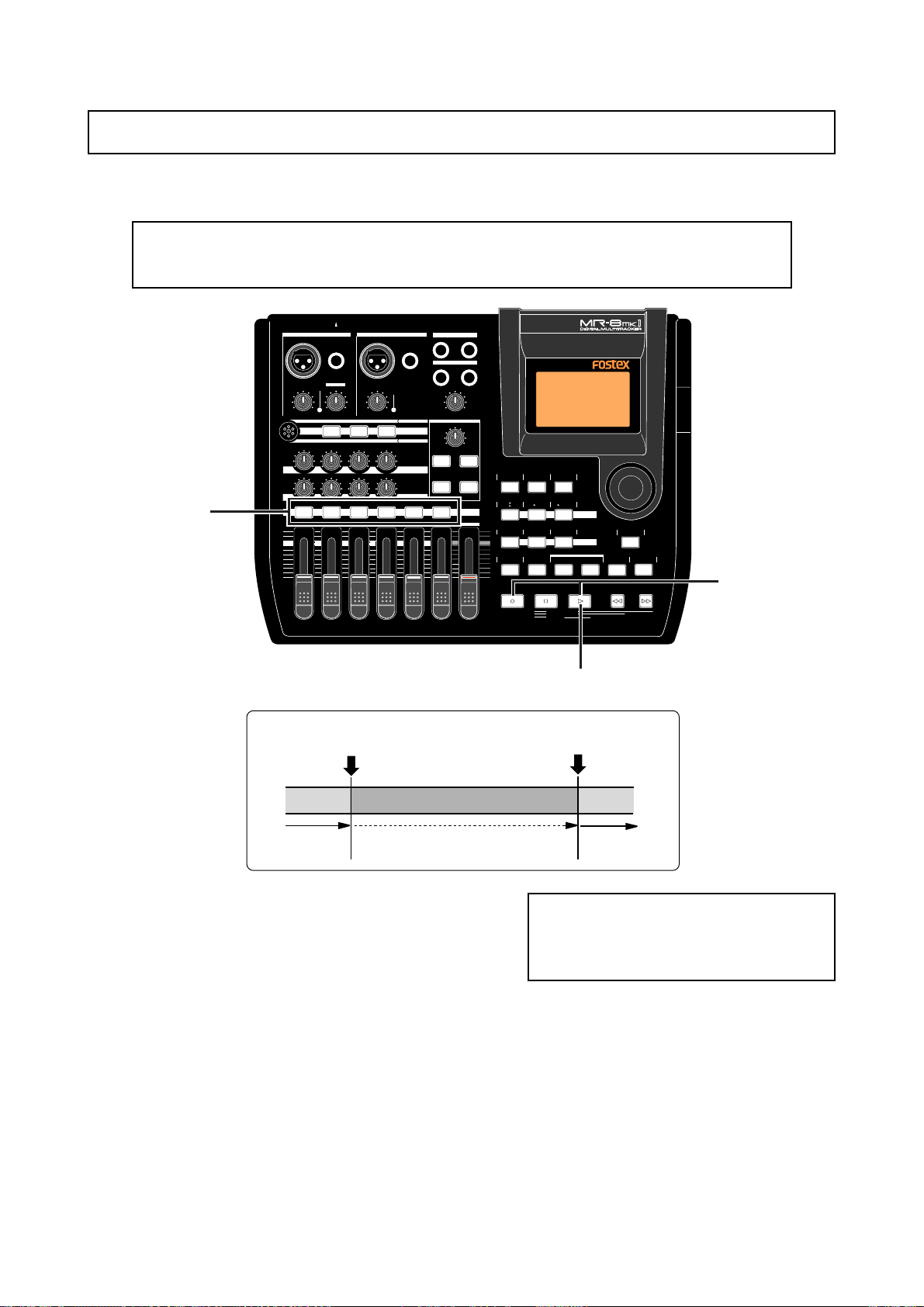
MR-8mkII Owner’s Manual (Punch in/out)
Punch in/out using the keys on the top panel
You can make punch in/out manually by using the [RECORD] and [PLAY] keys on the MR-8mkII
top panel.
<Note>:
The punch in/out operation by yourself using the keys on the top panel sometimes
prevents you from concentrating on playing. In such a case, ask someone to operate the MR8mkII, or use either of the other two punch in/out methods described later.
INPUT A SELECT
1
INPUT A INPUT B
UNBAL
/GUITAR
BAL
DISTORTION
PEAK
TRIM
LINE
MIN
MIC
MIC
BRIT STACK US METAL 60'S COMBO
010
RL
LR LR LR
1 2 3 4 5/6 7/8 MASTER
MAX
MIN
BAL
GUITAR
TRIM
PEAK
LINE
MAX
MIC
TUBECONDENSERDYNAMIC
100100100
AMP SIMULATION
EFFECT SEND
UNBAL
MIC SIMULATION
INPUT A
PAN
ST OUT
L
PHONES
1
PHONES VOL
MAX
MIN
EFFECT
REVERB/DELAY TIME
MIN MAX
PLATE DELAY
REC SELECT
R
2
HALLROOM
RHYTHM
TIME BASE
GUIDE
1-4
1-6
MAX
AUTO PUNCH
MIN
PQR6
CONTRAST
SELECT
5/6
7/8
1-8
MNO5JKL4
PLAY MODE
NEW
SONG
STEREO
7/8
WAV FILE
BOUNCE
GHI3DEF2ABC1
BRIGHTNATURALPOWERFUL
MASTERING
LOCATE
A / IN B / OUT
PLAYSTOPRECORD REWIND F FWD
LOCATE REC END
LOCATE ABS ZERO
A-B PLAY
STORE
MENU/ENTER
UNDO/REDO
DELETE+-_0YZ9VWX8STU7
3
2,4
Press the [RECORD] key
while holding down the [PLAY] key.
(Punch in)
Playback
1) Press the [REC SELECT] key for the track y ou
are going to make punch in/out recording.
The track is record-armed.
2) Locate the recorder to the point before the punchin point and press the [PLAY] key to start
playback.
It may be a good idea to play the instrument
along with the playback sound, so that you can
get the tempo and feel.
3) When the recorder reaches at the point you want
to punch in, press the [RECORD] key while holding
down the [PLA Y] key (see <Important note> below>).
The armed track is punched in (i.e. starts
recording).
Press only the [PLAY] key.
(Punch out)
Recording
Playback
<Important note>
You cannot punch in by only pressing the
[RECORD] key. You need to hold down the
[PLAY] key when pressing the [RECORD] key.
4) When the recorder reaches at the point you want
to punch out, press only the [PLAY] key .
The recorder status switches from recording
to playback.
5) Press the [STOP] key to stop the recorder.
6) Rewind the recorder and play back the part y ou
performed the punch in/out recording to chec k
the result.
If you are not satisfied with the result, use the
undo function to cancel the punch in/out
recording and try again.
54
Page 55
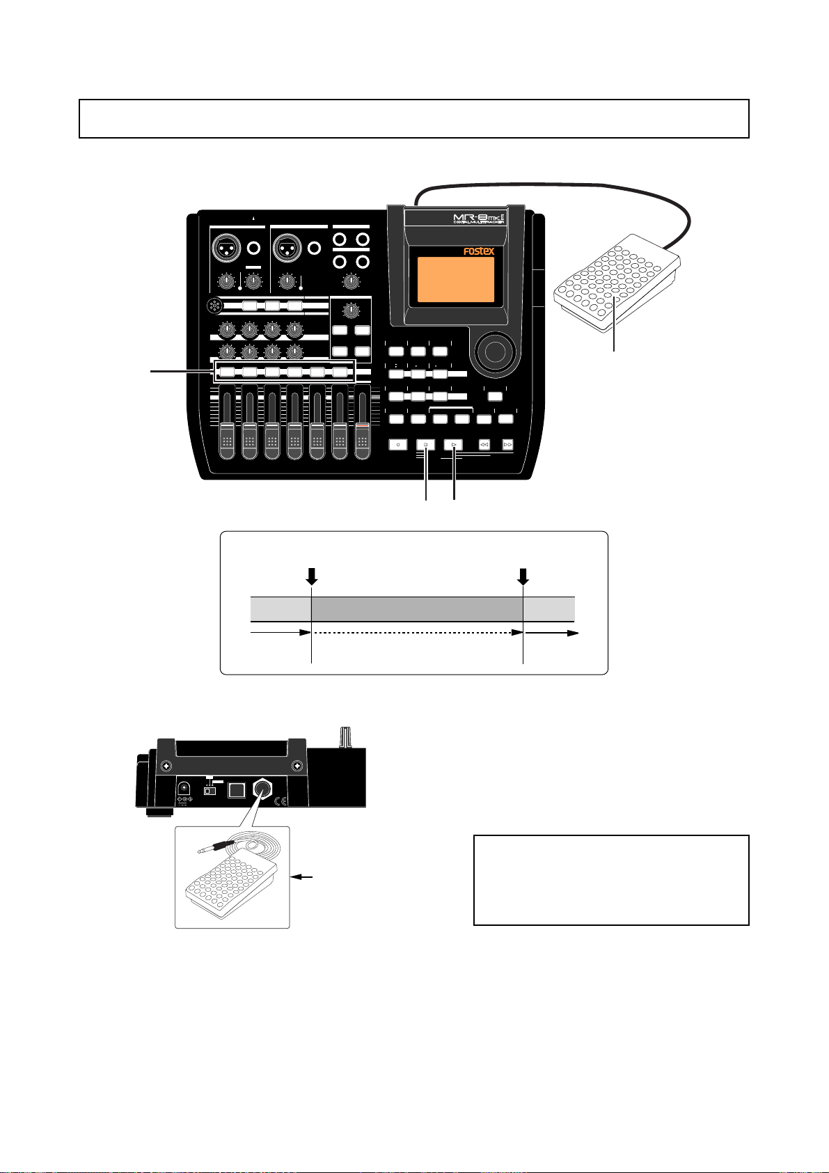
MR-8mkII Owner’s Manual (Punch in/out)
Punch in/out using the foots witch
You can make hands-free punch in/out recording using an unlatched-type footswitch.
INPUT A SELECT
INPUT A INPUT B
UNBAL
/GUITAR
BAL
PEAK
TRIM
LINE
MIC
MIC
BRIT STACK US METAL 60'S COMBO
010
RL
2
1 2 3 4 5/6 7/8 MASTER
MAX
MIN
BAL
GUITAR
DISTORTION
TRIM
MIN
LINE
MAX
MIC
TUBECONDENSERDYNAMIC
100100100
LR LR LR
PEAK
UNBAL
MIC SIMULATION
INPUT A
AMP SIMULATION
EFFECT SEND
PAN
ST OUT
L
PHONES
1
PHONES VOL
MAX
MIN
EFFECT
REVERB/DELAY TIME
MIN MAX
PLATE DELAY
REC SELECT
R
2
HALLROOM
RHYTHM
TIME BASE
CONTRAST
GUIDE
SELECT
5/6
1-4
1-6
MAX
AUTO PUNCH
MIN
PQR6
STEREO
NEW
7/8
1-8
7/8
WAV FILE
SONG
BOUNCE
MNO5JKL4
PLAY MODE
GHI3DEF2ABC1
BRIGHTNATURALPOWERFUL
A / IN B / OUT
LOCATE REC END
LOCATE ABS ZERO
A-B PLAY
MENU/ENTER
MASTERING
LOCATE
STORE
PLAYSTOPRECORD REWIND F FWD
UNDO/REDO
DELETE+-_0YZ9VWX8STU7
4,5
Press the footswitch.
(Punch in)
Playback
1) Connect the footswitch to the [FOOT SW] jack
on the MR-8mkII rear panel.
ON
DC IN
LIGHT
OFF
POWER USB FOOT SW
12V
[FOOT SW] jack
Unlatched-type
footswitch
3,7
6
Press the footswitch.
(Punch out)
Recording
Playback
4) When the recorder reaches at the point you want
to punch in, press the f oots witc h.
The armed track is punched in (i.e. starts
recording).
5) When the recorder reaches at the point you want
to punch out, press the f oots witc h a gain.
The recorder status switches from recording
to playback.
<Note>:
You cannot perform another punch
in/out recording successively.
To perform punch in/out recording in another part, stop the recorder and perform
the steps above again.
2) Press the [REC SELECT] key for the track y ou
are going to make punch in/out recording.
The track is record-armed.
3) Locate the recorder to the point before the punchin point, and press the [PLAY] key to start play
back.
It may be a good idea to play the instrument
along with the playback sound, so that you can
get the tempo and feel.
6) Press the [STOP] key to stop the recor der.
7) Rewind the recorder and play bac k the part you
performed the punch in/out recording to chec k
the result.
If you are not satisfied with the result, use the
undo function to cancel the punch in/out
recording and try again.
55
Page 56
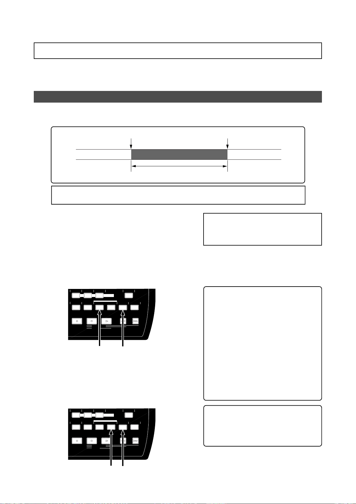
MR-8mkII Owner’s Manual (Punch in/out)
Auto punc h in/out
By setting the punch-in and punch-out points in advance, The recorder automatically makes
punch in/out recording for you. You can rehearse punch in/out recording as many times you
like.
Setting the punch-in and punch-out points
You can set the punch-in and punch-out points on-the-fly while playing back the recorder (as
well as you can set them while the recorder is stopped at the desired position).
Punch-in point
Part replaced with a new recording
<Note>:
You cannot make punch-in/out recording on a song which is protected. Release the song
protection before making punch-in/out recording.
1) Start playback from the beginning of the song
(or from a point before the point where y ou want
to make punching in) by pressing the [PLAY] key.
2) When the recorder reaches at the point where
you want to make punching in, press the
[LOCATE A/IN] key while holding down the
[STORE] key.
The display briefly shows "Store LOCATE A"
and the time data when you press the
[LOCATE A/IN] key is set as the punch-in point.
AUTO PUNCH
PQR6
MNO5JKL4
PLAY MODE
BRIGHTNATURALPOWERFUL
MASTERING
LOCATE
A / IN B / OUT
PLAYSTOPRECORD REWIND F FWD
LOCATE REC END
LOCATE ABS ZERO
A-B PLAY
STORE
MENU/ENTER
UNDO/REDO
DELETE+-_0YZ9VWX8STU7
Punch-out point
<Note>:
If you are not satisfied with the
punch-in or punch-out point you set, simply redo the operation above. The new time
data overwrites the previous one.
4) Stop the recorder after setting the punch-in and
punch-out points, and rewind the recor der to the
beginning of the song (or to a point before the
point where you want to make punching in).
<Hint>: To rewind the recorder to the be-
ginning of the song after setting the
punch-out point, press the [REWIND] key
while holding down the [STOP] key.
To locate before the punch-in point, carry
out the following.
3) When the recorder reaches at the point where
you want to make punching out, press the
[LOCA TE B/OUT] key while holding down the
[STORE] key.
The display briefly shows "Store LOCATE B"
and the time data when you press the
[LOCATE B/OUT] key is set as the punch-out
point.
AUTO PUNCH
PQR6
MNO5JKL4
PLAY MODE
BRIGHTNATURALPOWERFUL
MASTERING
LOCATE
A / IN B / OUT
PLAYSTOPRECORD REWIND F FWD
LOCATE REC END
LOCATE ABS ZERO
A-B PLAY
STORE
MENU/ENTER
UNDO/REDO
DELETE+-_0YZ9VWX8STU7
(1) While the recorder is stopped, press
the [LOCATE A/IN] key.
The recorder immediately locates to
the punch-in point and stops.
(2) Press the [REWIND] key to move back
the recorder and press the [STOP] key
at the desired point.
<Hint>: The punch-in and punch-out
points you set also can be used for the
locate function, playback by the play
mode and part editing (see pages 47 and
103).
56
Page 57
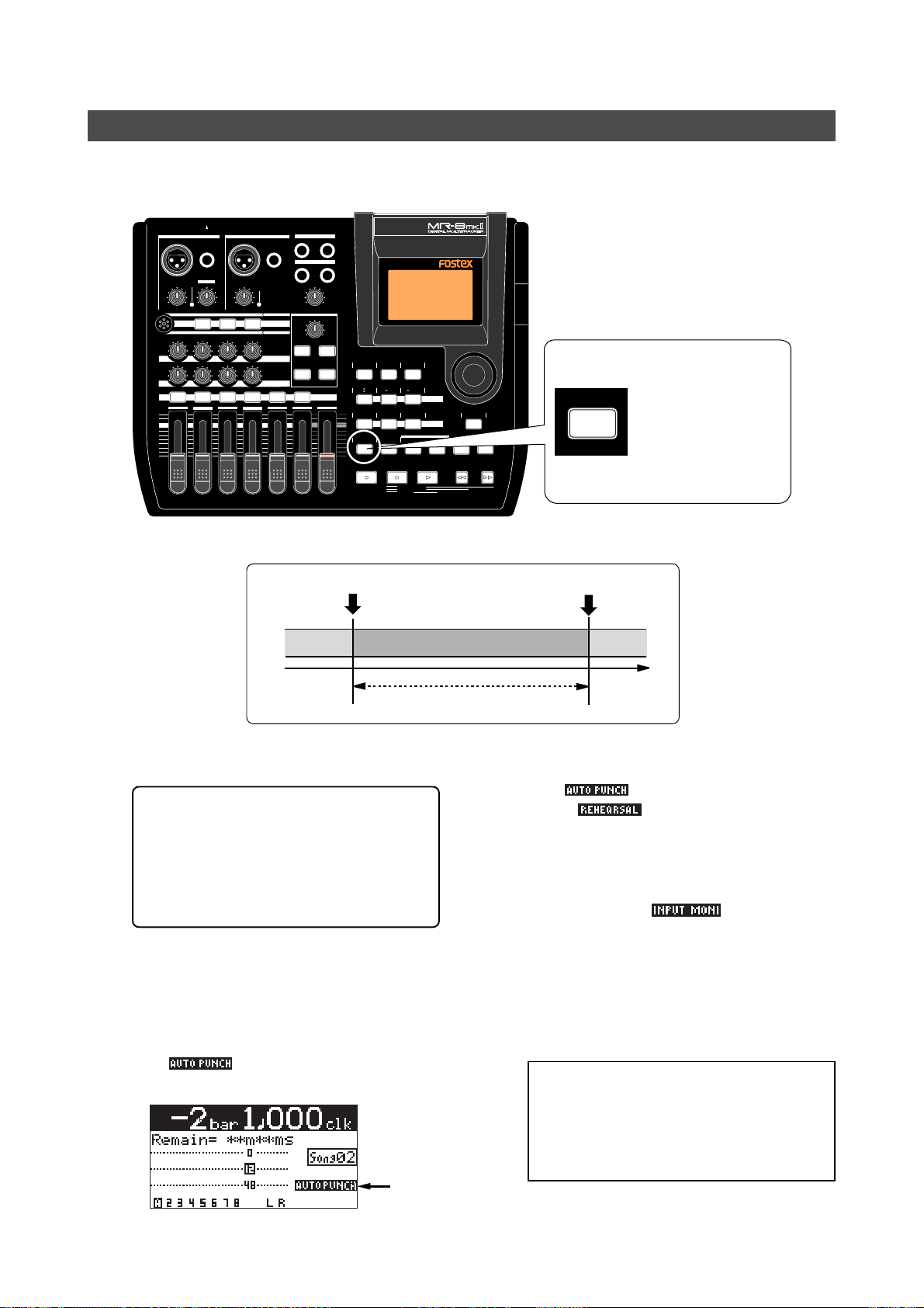
MR-8mkII Owner’s Manual (Punch in/out)
Rehearsal for auto punch in/out
After setting the punch-in and punch-out points appropriately, you can rehearse the auto punch
in/out for checking the punch-in and -out points or practicing punch-in and -out timing.
INPUT A SELECT
INPUT A INPUT B
UNBAL
/GUITAR
BAL
PEAK
TRIM
LINE
MIC
MIC
BRIT STACK US METAL 60'S COMBO
010
RL
1 2 3 4 5/6 7/8 MASTER
MAX
MIN
BAL
GUITAR
DISTORTION
TRIM
MIN
LINE
MAX
MIC
TUBECONDENSERDYNAMIC
100100100
LR LR LR
PEAK
UNBAL
MIC SIMULATION
INPUT A
AMP SIMULATION
EFFECT SEND
PAN
ST OUT
L
PHONES
1
PHONES VOL
MAX
MIN
EFFECT
REVERB/DELAY TIME
MIN MAX
PLATE DELAY
REC SELECT
R
2
<How to make auto punch in/out mode active>
HALLROOM
RHYTHM
TIME BASE
CONTRAST
GUIDE
SELECT
1-4
5/6
STEREO
NEW
7/8
1-8
1-6
7/8
WAV FILE
SONG
BOUNCE
MNO5JKL4
PLAY MODE
GHI3DEF2ABC1
BRIGHTNATURALPOWERFUL
MASTERING
LOCATE
A / IN B / OUT
PLAYSTOPRECORD REWIND F FWD
LOCATE REC END
LOCATE ABS ZERO
A-B PLAY
MENU/ENTER
UNDO/REDO
STORE
DELETE+-_0YZ9VWX8STU7
MAX
AUTO PUNCH
MIN
PQR6
AUTO PUNCH
PQR6
Pressing the [AUTO
PUNCH] key switches
the auto punch in/out
mode on or off.
Each press of the
[AUTO PUNCH] key
turns on or off the indicator.
Punch-in point
Playback
1) Locate the recorder to the point before the punchin point (or the beginning of the song).
<Tip>: You can immediately locate to the
punch-in point by pressing the [LOCATE
A/IN] key. Therefore, by pressing the [LOCATE A/IN] key, followed by the [REWIND] key then the [STOP] key, you can
easily locate to the point before the
punch-in point.
2) Press the [REC SELECT] key of the track you are
going to make punch in/out operation to arm the
track.
3) Press the [AUT O PUNCH] ke y to make the auto
punch mode active.
The " " icon is now shown on the
screen.
Lighting
Punch-out point
Playback
Input monitor
4) Press the [PLAY] key.
The recorder starts punch in/out rehearsal.
The "
to the "
" icon on the display changes
" icon.
In the rehearsal mode, the recorder automatically switches the monitor of the armed track
from "repro" to "input" at the punch-in point,
but actual recording is not made (the [RECORD]
key flashes while "
" is shown on the
display.
By repeating the operation above, you can practice auto in/out operation as many times as
you like.
5) After the punch-out point is passed, locate the
recorder back to the beginning position.
<Note>:
By using the loop function when
rehearsing the auto punch in/out operation,
you can concentrate on playing without the
need of troublesome operation of the MR8mkII. See page 48 for details about the loop
function.
57
Page 58
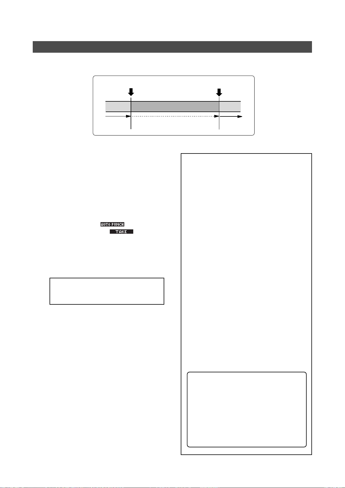
MR-8mkII Owner’s Manual (Punch in/out)
Actual auto punch in/out
After rehearsing the auto punch-in/out operation, it's time for executing actual auto punch in/
out operation.
Punch in point
Playback
1) Locate the recorder to the point before the punchin point.
2) Make sure that "AUTO PUNCH" is shown on the
screen (i.e. the auto punch mode is active).
If it is not shown, press the [AUTO PUNCH] key.
3) Press the [RECORD] key while holding down the
[PLAY] key.
The recorder starts executing actual punch in/
out operation. The "
display changes to the "
Unlike the rehearsal, the recorder
automatically starts recording when it reaches
the punch-in point, then automatically stops
recording and exits the auto punch mode at
the punch-out point.
<Note>:
out recording you made by pressing the
[UNDO/REDO] key.
You can cancel the auto punch in/
" icon on the
" icon.
Recording
Punch out point
Playback
<Note>:
In addition to the punch in/out function, the MR-8mkII allows you to edit the recorded material using the following editing
functions.
• Deleting the whole data on the desired
track (using the "Erase Track" menu item).
See page 96.
• Copying all data on a track and pasting it
to another track (using the "Copy Paste
Track" menu item). See page 97.
• Moving the desired track data to the other
track(s) (using the "Move Track" menu
item). See page 99.
• Exchanging all track data between tracks
(using the "Change Track" menu item). See
page 101.
• Deleting the desired part (using the "Erase
Part" menu item). See page 105.
• Pasting the desired part(s) to the other
track(s) (using the "Copy Paste Part" menu
item or the "Copy Part" and "Paste Part"
menu items). See pages 106 and 108.
• Moving the desired part(s) to the other
track(s) (using the "Move Part" menu item).
See page 111.
• Exchanging parts between tracks (using the
"Change Part" menu item). See page 113.
58
<About "part">
A "part" is defined as audio data between
the "LOCATE A" and "LOCATE B" points.
Therefore, you have to set the "LOCATE
A" and "LOCATE B" points when editing a
"part".
The punch-in and punch-out points set
for the auto punch in/out function also
can be used as the "LOCATE A" and "LOCATE B" points.
Page 59

MR-8mkII Owner’s Manual (Using effects)
Using effects
The MR-8mkII provides the insert effects for recording (microphone
and amplifier simulation effects), the delay/reverb effects for track
bounce or mixdown (for tracks 1 through 4 only), and the mastering effects for L/R mix.
59
Page 60
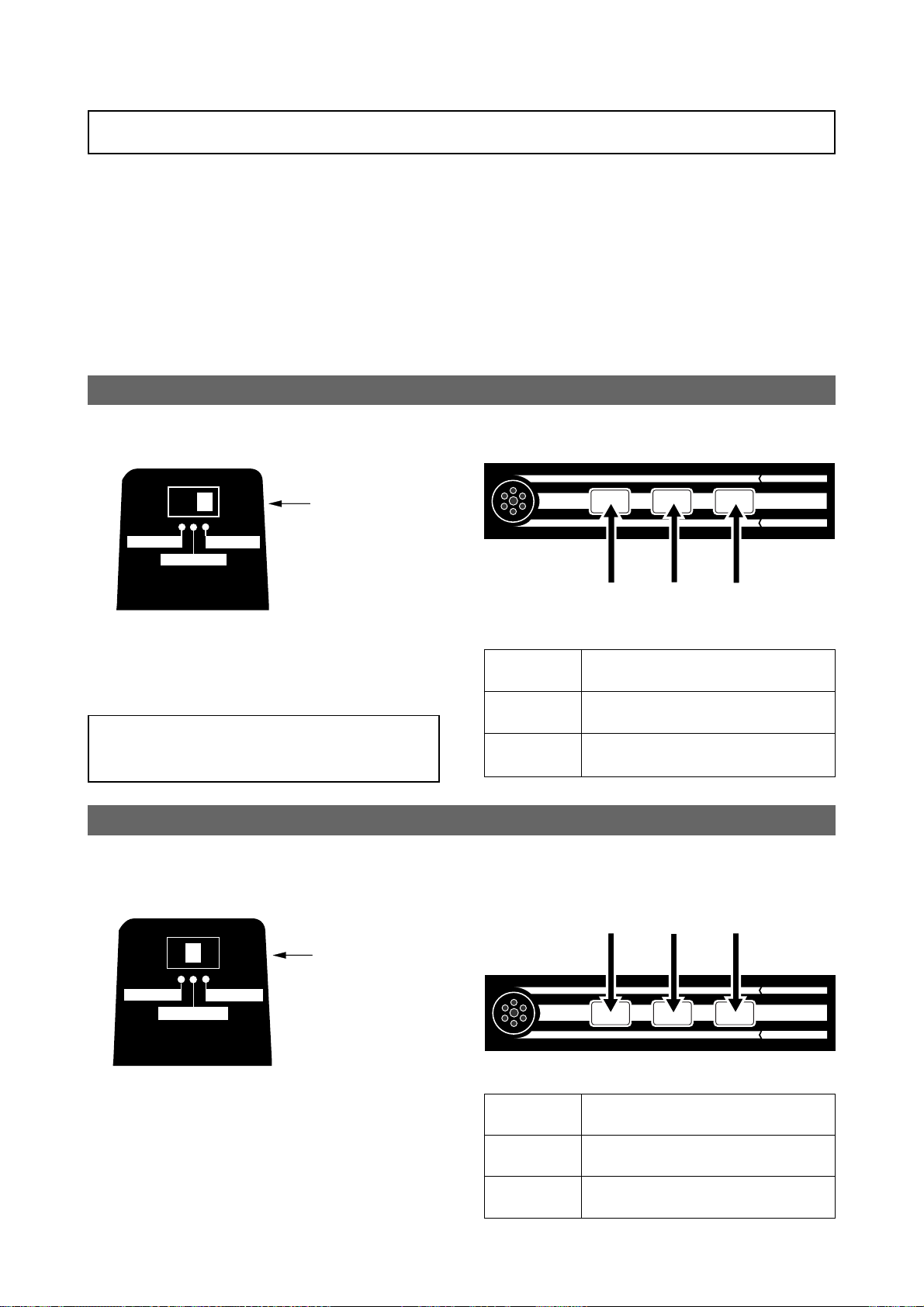
MR-8mkII Owner’s Manual (Using effects)
Using the insert effects
The [INPUT A] channel of the MR-8mkII provides two types of insert effects: microphone and
amplifier simulation effects. These effects can be used during recording.
These effects simulate popular microphones and guitar amplifiers. If you use the microphone
simulation effect when you record an acoustic guitar through your microphone, you can make
recording as if you are using a famous microphone. If you use the guitar amplifier simulation
effect when you record an electric guitar directly connected to the MR-8mkII, you can make
recording as if you are using a famous guitar amplifier.
Note that you cannot get exactly the same sound as the original microphone/guitar amplifier by
using simulation effects.
Mic simulation effects
You can use mic simulation effects when the [INPUT A SELECT] switch on the rear panel is set to
"MIC/LINE".
MIC SIMULATION
TUBECONDENSERDYNAMIC
INT MIC
Set to the "MIC/LINE"
position
MIC/LINE
GUITAR
MIC
BRIT STACK US METAL 60'S COMBO
INPUT A
AMP SIMULATION
INPUT A SELECT
By pressing the appropriate key, you can
choose from among three mic simulation effects: DYNAMIC, CONDENSER and TUBE (the
indicator of the key lights up).
<Note>:
by setting the [INPUT A SELECT] switch to the “INT
MIC” position, the insert effects are not available.
When you use the internal microphone
“DYNAMIC”
“CONDENSER”
• Details of each mic simulation effect
DYNAMIC
CONDENSER
TUBE
Simulates the sound of a popular dynamic microphone.
Simulates the sound of a popular condenser microphone for professional use.
Simulates the sound of a popular tube
microphone for professional use.
“TUBE”
Amp simulation effects
You can use mic simulation effects when the [INPUT A SELECT] switch on the rear panel is set to
"GUITAR". When the switch is set to "GUITAR", you can also use the distortion (adjusted by the
[DISTORTION] control), as well as the insert effects.
“60”s COMBO”
MIC SIMULATION
TUBECONDENSERDYNAMIC
INPUT A
AMP SIMULATION
INT MIC
INPUT A SELECT
MIC/LINE
GUITAR
Set to the "GUITAR"
position
“BRIT STACK”
MIC
BRIT STACK US METAL 60'S COMBO
“US METAL”
You can choose from three guitar amp simulation effects: BRIT STACK, US METAL and 60's
COMBO (the selected key lights up).
• Amp simulation effects details
BRIT STACK
US MET AL
60’s COMBO
Simulates a popular British 800-series
tube guitar amp head.
Simulates a popular US high gain metal
guitar amplifier.
Simulates a popular tube combo guitar
amplifier.
60
Page 61
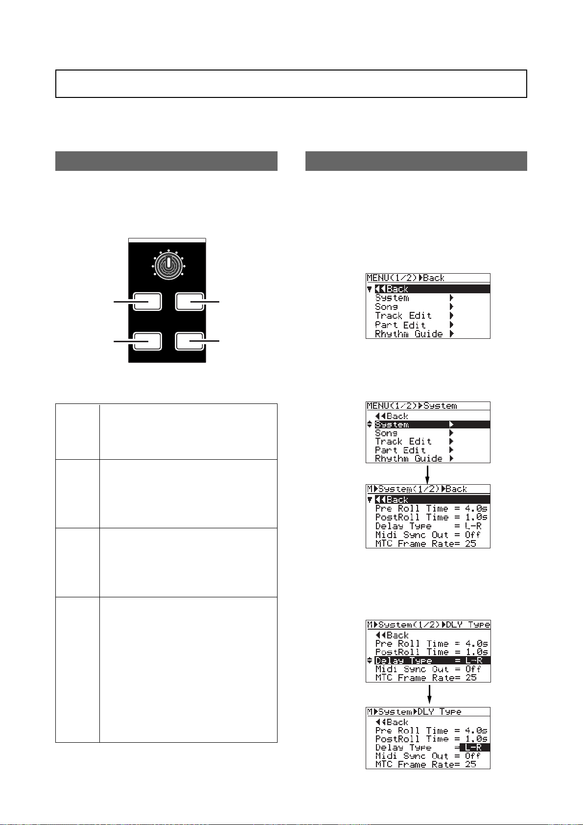
MR-8mkII Owner’s Manual (Using effects)
Using the reverb or dela y
The MR-8mkII has the original built-in reverb/delay processor featuring the newly-developed
algorithm. You can apply the reverb or delay to playback signals of tracks 1 through 4 during
mixdown and track bouncing.
Selecting an effect type
You can select an effect type from among three
reverb options (ROOM, HALL and PLATE) and
a delay (DELAY) by using the keys in the [EFFECT] section shown below.
EFFECT
REVERB/DELAY TIME
MIN MAX
[ROOM] key
PLATE DELAY
[PLA TE] key
Details of each effect type
Simulates reverberation in a medium-sized
ROOM
room. When you select "ROOM", you can
adjust the reverb time using the [REVERB/
DELA Y TIME] control.
HALLROOM
[HALL] key
[DELAY] key
Selecting a delay type
When you use the delay effect, you can select
a delay type.
1) While the recorder is stopped, press the
[MENU/ENTER] key to enter the menu mode.
The display now shows the first page of the
menu selection screen, where "<< Back" is
highlighted initially.
2) Rotate the JOG dial to select "System", and press
the [MENU/ENTER] key.
The display now shows the system menu
screen, where "<< Back" is highlighted.
HALL
PLATE
DELAY
Simulates reverberation in a hall with moderate early reflection.
When you select "HALL", you can adjust the
reverb time using the [REVERB/DELAY
TIME] control.
Simulates a plate reverb with a wide frequency range.
When you select "PLATE", you can adjust the
reverb time using the [REVERB/DELAY
TIME] control.
Adds delay effects. You can select the desired delay types using the "Delay Type" item
of the System menu in the menu mode (you
can easily access to the "Delay Type" setting
screen by a long press of the [DELAY] key).
Three delay types are available: Mono, L-R
and Diff. See below for details.
When you select "ROOM", you can adjust
the delay time using the [REVERB/DELAY
TIME] control.
3) Rotate the JOG dial to select "Delay Type" and
press the [MENU/ENTER] key.
The current delay type starts flashing and you
can now select from among three options
shown below ("L-R" is initially selected).
61
Page 62
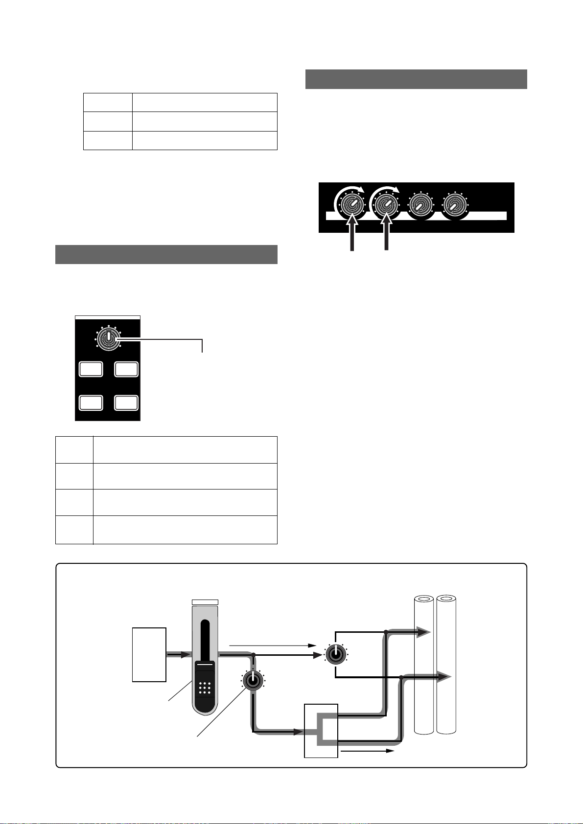
MR-8mkII Owner’s Manual (Using effects)
You can choose from among the following three
delay types.
L - R
Mono
Diff
L-R delay (default)
Mono delay
Diffusion delay
4) Rotate the JOG dial to select the desired delay
type and press the [MENU/ENTER] key.
The selected delay type is set, while the
display returns to the previous screen.
5) Press the [STOP] key to quit the menu mode.
Adjusting the delay/reverb time
You can adjust the reverb time or delay time
using the [REVERB/DELAY TIME] control, depending on the selected effect type.
EFFECT
REVERB/DELAY TIME
MIN MAX
HALLROOM
[REVERB / DELAY TIME] control
Adjusting the effect send levels
To apply the effect (reverb or delay) to tracks
1 through 4, adjust the [EFFECT SEND] control for each track to adjust the level of the
track signal sent to the effect processor.
In the example as illustrated below, tracks 1
and 2 signals are sent to the effect processor.
010
100100100
As shown in the signal flowchart below, a track
(playback) signal after the track fader is fed
to the [EFFECT SEND] control and adjusted,
then fed to the effect processor input.
The effect processor's stereo output signals
(wet signals) and stereo (L/R) signals (dry signals) are merged together and then output
from the [STEREO OUT] jacks.
EFFECT SEND
PLATE DELAY
signal sent to the effect processor is affected
by the track fader (i.e. a track fader must be
raised to send track signal to the effect processor). The signal which passes through a
As you can see in the flowchart below, the
HALL
ROOM
PLATE
DELAY
Adjusts the reverb time within the range between
1.0 s and 6.0 s (center position: 3.0 s)
Adjusts the reverb time within the range between
0.1 s and 2.0 s (center position: 1.0 s)
Adjusts the reverb time within the range between
0.5 s and 4.0 s (center position: 2.0 s)
Adjusts the delay time within the range between
100 ms to 1000 ms (center position: 300 ms)
fader is generally called a "post fader signal".
<Signal flow from a trac k to the eff ect processor (onl y Track 1~ 4)>
1
Playback
Dry sound
Track 1
Adjusts the track
playback level
Adjusts the send level to the
effect processor
10
0
EFFECT SEND
Delay
or
Reverb
PAN
R
L
Wet sound
STEREO BUSS
L
R
62
Page 63
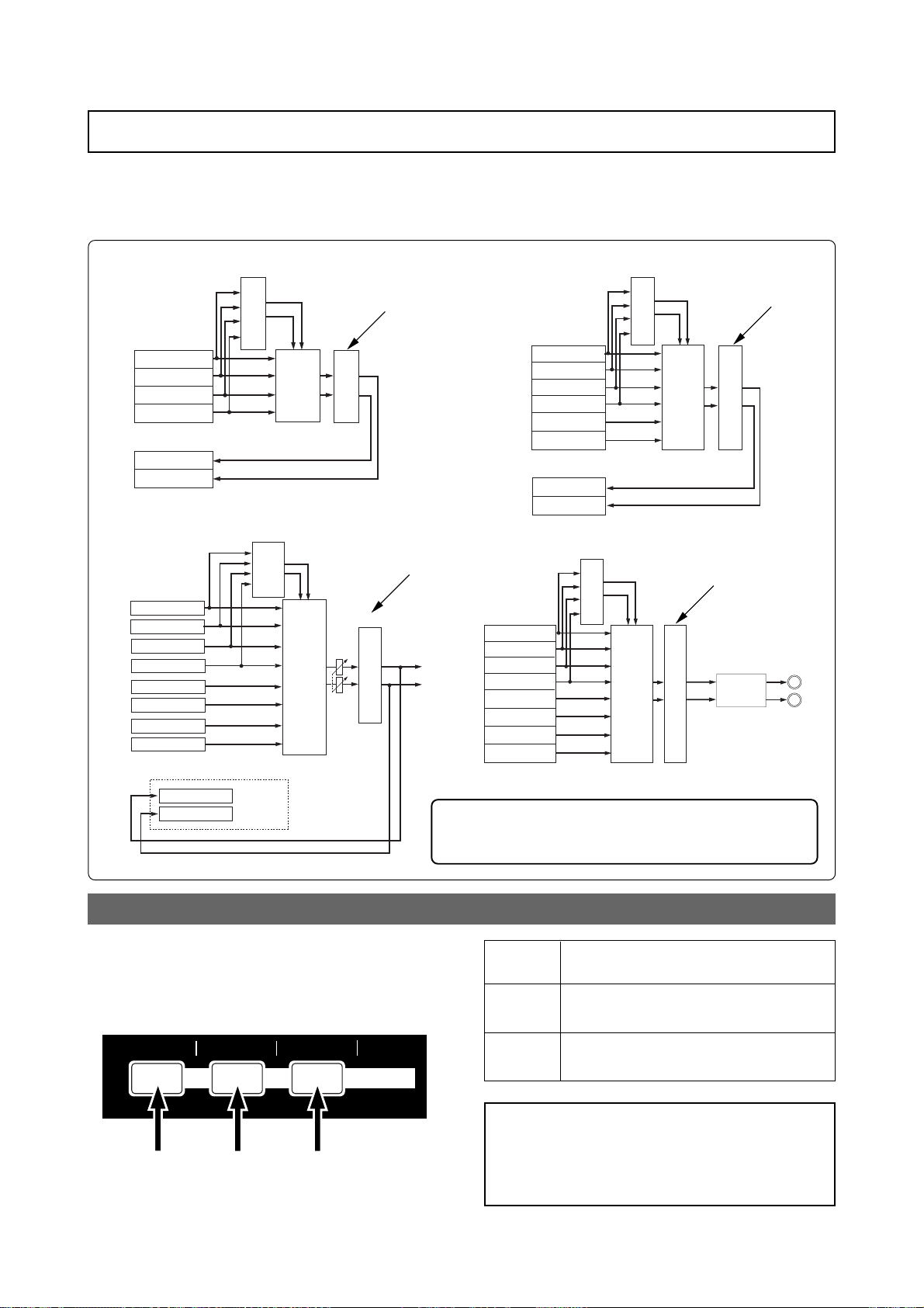
MR-8mkII Owner’s Manual (Using effects)
Using the mastering effects
The MR-8mkII provides the dedicated mastering effects for the L/R stereo buss.
You can use the mastering effects when bouncing more than one track to stereo tracks or when
mixing down tracks 1 through 8 to stereo and sent to an external master recorder for recording.
<Bouncing tracks 1 through 4 to track 5/6>
Mastering effects
Mastering effects
Mixing
Trk 1
Trk 2
Trk 3
Trk 4
Trk 5
Trk 6
Playback
Playback
Playback
Playback
Playback
Record
Record
Reverb
or Delay
bouncing
<Bouncing tracks 1 through 8 to the New song>
Reverb
Trk 1
Trk 2
Trk 3
Trk 4
Trk 5
Trk 6
Trk 7
Trk 8
or Delay
Playback
Playback
Playback
Playback
Playback
Playback
Playback
Playback
Mastering effects
Mastering effects
Mixing
STEREO OUT (L, R)
<Bouncing tracks 1 through 6 to track 7/8>
Reverb
or Delay
Playback
Trk 1
Playback
Trk 2
Trk 3
Trk 4
Trk 5
Trk 6
Trk 7
Trk 8
Playback
Playback
Playback
Playback
Record
Record
Mixing
bouncing
<Mixing down tracks 1 through 8>
Mastering effects
Mastering effects
Mixing
Trk 1
Trk 2
Trk 3
Trk 4
Trk 5
Trk 6
Trk 7
Trk 8
Playback
Playback
Playback
Playback
Playback
Playback
Playback
Playback
Reverb
or Delay
Mastering effects
Mastering effects
D/A
Record
Trk 7
Trk 8
Record
New Song
bouncing
Selecting the desired effect type
Three mastering effect types are available. You
can select the desired type using the [MASTERING] keys (POWERFUL, NATURAL and
BRIGHT).
BRIGHTNATURALPOWERFUL
MASTERING
MNO5JKL4
Each effect type has the following character.
Select the appropriate type.
See "Track bounce" on page 65 for details about track
bounce which allows mixing multiple tracks to stereo.
See "Mixdown" on page 44 for details about mixdown.
POWERFUL
NA TURAL
BRIGHT
<Note>:
Adds power to the sound. Good for rock.
Slightly adds power to the sound. Good for
acoustic music.
Add brightness to the sound. Good for use
when the mixed sound is dark.
By activating the mastering effect, the output level raises. Therefore, be careful of the level
change when monitoring via headphones or monitor speakers, as well as when adjusting the recording level of an external recorder.
63
Page 64

MR-8mkII Owner’s Manual (Using effects)
64
Page 65

MR-8mkII Owner’s Manual (Track bouncing)
Track bouncing
This chapter describes track bouncing which is an important
function in the recording process.
The track bouncing mixes several tracks and records onto other
two tracks. By using this function, you can record more sound
materials to the MR-8mkII tracks.
Three track bouncing modes are available:
(1) Bouncing tracks 1 through 4 to tracks 5/6.
(2) Bouncing tracks 1 through 6 to tracks 7/8
(3) Bouncing tracks 1 through 8 to tracks 7/8 of a new song.
In any mode, you can apply a reverb (or delay) to tracks 1
through 4 when bouncing to two tracks in stereo. Furthermore, you can apply the mastering effect to the mixed signals.
65
Page 66
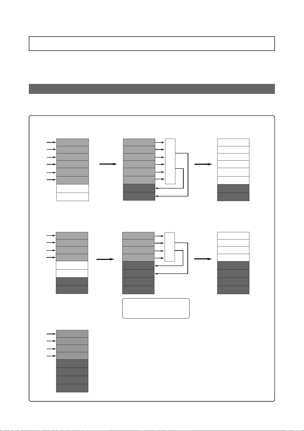
MR-8mkII Owner’s Manual (Track bouncing)
Track 4
Track 3
Track 2
Track 1
Track 5
Track 6
Track 7
Track 8
Preliminary knowledge
Before executing track bouncing, read "Track bouncing example" below and "Track bouncing
signal flow" on the next page.
T rac k bouncing e xample
You can record more than eight materials using the track bouncing function as shown in the
following example.
<Step 1>
Make recording to tracks 1 through 6.
Track 1
Track 2
Track 3
Track 4
Track 5
Track 6
Track 7
Track 8
<Step 4>
Overdub new materials to tracks 1
through 4.
<Step 2>
Bounce tracks 1 through 6 to tracks 7/8.
Track 1
Track 2
Track 3
Mixing
Track 4
Track 5
Track 6
Track 7
Track 8
<Step 5>
Bounce tracks 1 through 4 to tracks 5/6.
Track 1
Track 2
Mixing
Track 3
Track 4
Track 5
Track 6
Track 7
Track 8
<Step 3>
Delete tracks 1 through 6.
Track 1
Track 2
Track 3
Track 4
Track 5
Track 6
Track 7
Track 8
<Step 6>
Delete tracks 1 through 4.
Track 1
Track 2
Track 3
Track 4
Track 5
Track 6
Track 7
Track 8
<Step 7>
Overdub new materials to tracks 1
through 4.
Track 1
Track 2
Track 3
Track 4
Track 5
Track 6
Track 7
Track 8
In this step, you can make track
bouncing while listening to
tracks 7/8 as well.
66
Page 67
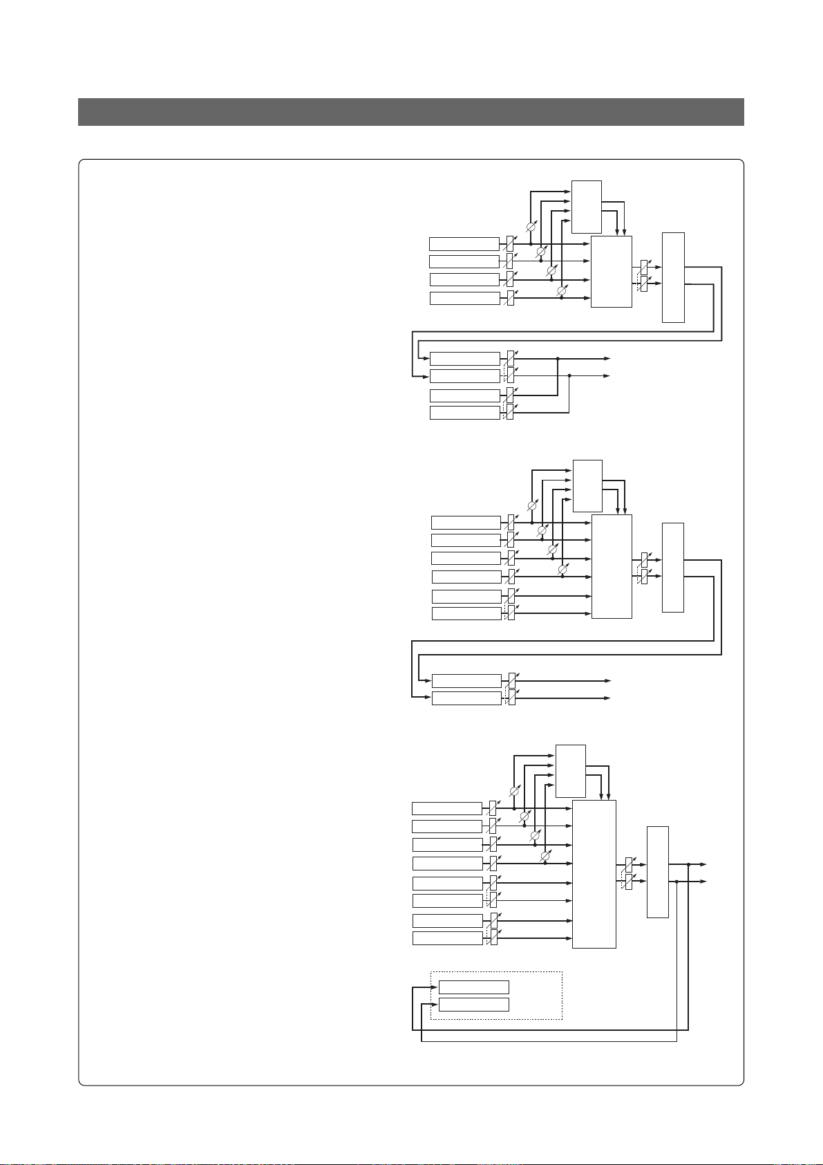
MR-8mkII Owner’s Manual (Track bouncing)
Signal flow of track bouncing
The following shows the signal flow for each of three track bouncing modes.
• "1-4 > 5/6" mode (see page 68)
In the "1-4 > 5/6" mode, tracks 1 through
4 are played back, mixed down to stereo,
and bounced to tracks 5/6.
You can apply a reverb (or delay) to tracks
1 through 4, as well as the mastering effect
to the mixed signals.
From headphones (or monitor speakers),
you can hear the signals bounced to tracks
5/6 (i.e. mixed signals) as well as playback
signals of tracks 7/8.
• "1-6 > 7/8" mode (see page 70)
In the "1-6 > 7/8" mode, tracks 1 through
6 are played back, mixed down to stereo,
and bounced to tracks 7/8.
In this mode, you can apply a reverb (or
delay) to tracks 1 through 4, as well as the
mastering effect to the mixed signals.
From headphones (or monitor speakers),
you can hear the signals bounced to tracks
7/8 (i.e. mixed signals).
Trk 1
Trk 2
Trk 3
Trk 4
Trk 5
Trk 6
Trk 7
Trk 8
Trk 1
Trk 2
Trk 3
Trk 4
Trk 5
Trk 6
Playback
Playback
Playback
Playback
Record
Record
Playback
Playback
Playback
Playback
Playback
Playback
Playback
Playback
Reverb
Delay
Track bouncing
Reverb
Delay
Track bouncing
or
Mastering effects
Mixing
STEREO OUT (L, R)
or
Mastering effects
Mixing
• "1-8 > NEW SONG" mode (see page 72)
In the "1-8 > NEW SONG" mode, tracks 1
through 8 are played back, mixed down to
stereo, and bounced to tracks 7/8 of a new
song which is automatically created. So this
bouncing mode allows you to internally
record a stereo master without the need of
an external master recorder.
In this mode, you can apply a reverb (or
delay) to tracks 1 through 4, as well as the
mastering effect to the mixed signals.
From headphones (or monitor speakers),
you can hear the signals bounced to tracks
7/8 of the new song.
Trk 1
Trk 2
Trk 3
Trk 4
Trk 5
Trk 6
Trk 7
Trk 8
Trk 7
Trk 8
Trk 7
Trk 8
Playback
Playback
Playback
Playback
Playback
Playback
Playback
Playback
Record
Record
Record
Record
New Song
Reverb
or Delay
STEREO OUT (L, R)
Mixing
Track bounce
Mastering effects
STEREO OUT (L, R)
67
Page 68
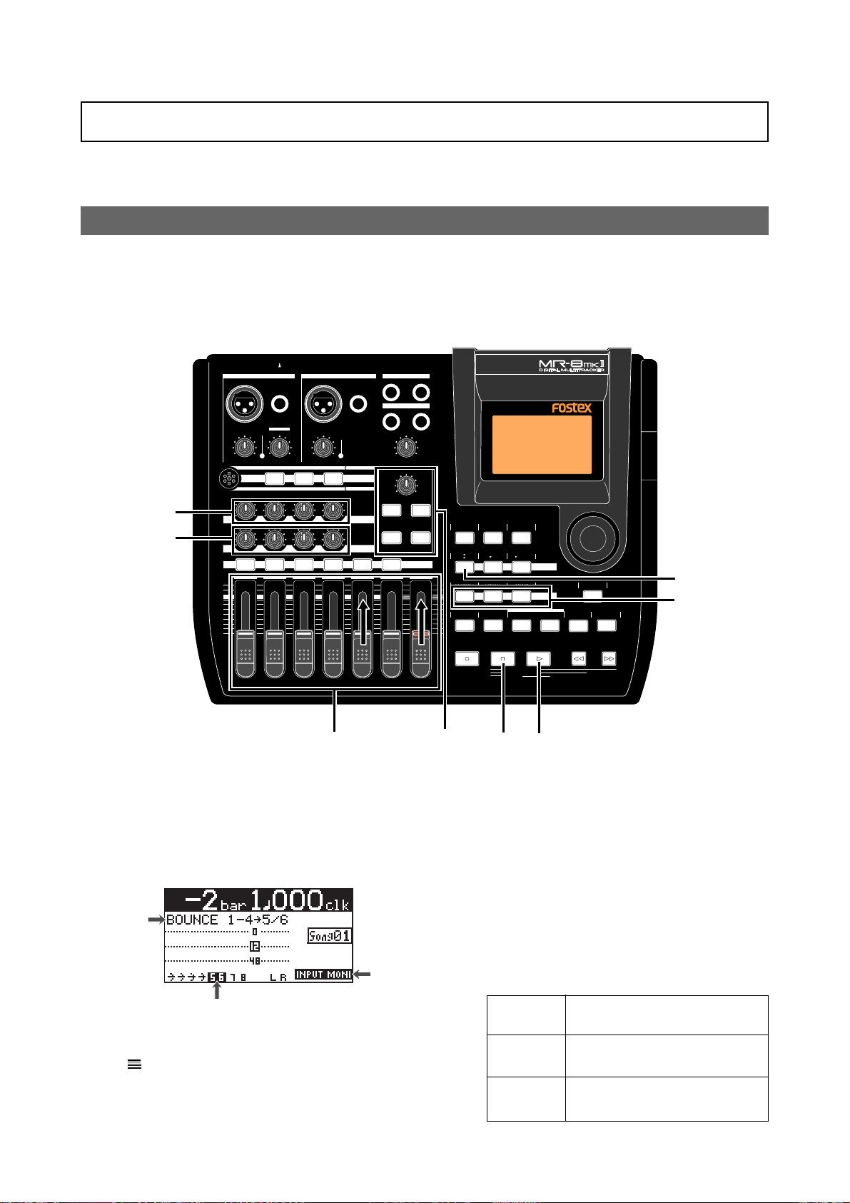
MR-8mkII Owner’s Manual (Track bouncing)
Bouncing tracks 1 thr ough 4 to tracks 5/6
You can bounce tracks 1 through 4 to tracks 5/6.
Before executing track bouncing, you can rehearse track bouncing as many times as you like.
Rehearsal of track bouncing
Before executing track bouncing, you can rehearse it. While rehearsing track bouncing, you can
control the playback level, panning and reverb (or delay) send setting of each source track, as
well as apply the mastering effect to the mixed L/R signals. We recommend to make rehearsal
thoroughly until you are satisfied with the sound.
The following assumes that the song you are going to execute track bouncing is loaded.
INPUT A SELECT
INPUT A INPUT B
UNBAL
/GUITAR
BAL
GUITAR
DISTORTION
PEAK
TRIM
LINE
MIN
MIC
MAX
MIC
BRIT STACK US METAL 60'S COMBO
4
4
MAX
MIN
100100100
010
LR LR LR
RL
1 2 3 4 5/6 7/8 MASTER
UNBAL
BAL
TRIM
PEAK
LINE
MIC
MIC SIMULATION
TUBECONDENSERDYNAMIC
INPUT A
AMP SIMULATION
EFFECT SEND
ST OUT
L
R
PHONES
2
1
PHONES VOL
MAX
MIN
EFFECT
REVERB/DELAY TIME
MIN MAX
HALLROOM
RHYTHM
TIME BASE
PLATE DELAY
PAN
REC SELECT
GUIDE
1-4
5/6
1-6
7/8
MAX
AUTO PUNCH
MIN
PQR6
SELECT
1-8
MNO5JKL4
PLAY MODE
NEW
SONG
LOCATE REC END
LOCATE ABS ZERO
A-B PLAY
CONTRAST
STEREO
7/8
WAV FILE
GHI3DEF2ABC1
BRIGHTNATURALPOWERFUL
A / IN B / OUT
BOUNCE
MASTERING
LOCATE
PLAYSTOPRECORD REWIND F FWD
MENU/ENTER
STORE
UNDO/REDO
DELETE+-_0YZ9VWX8STU7
1
4
2,4
1) Use the [1-4 > 5/6, 1-6 > 7/8] key to select the
"1-4 > 5/6" bounce mode.
Selecting this bounce mode automatically arms
tracks 5/6 and changes the monitoring mode
for these tracks to input monitoring mode.
The display looks like this:
Lighting
Lighting
Flashing
2) Raise the [5/6] fader and [MASTER] fader to the
"
" position. Set all the other track fader s down
to the minimum position.
4
5
3
3) Press the [PLAY] key to start playback from the
beginning of the song.
4) While playing back the song, adjust pla yback
levels of tracks 1 through 4 using the trac k
faders.
You can also adjust panning for tracks 1
through 4 and apply the reverb or delay to
these tracks, as well as apply the mastering
effect to the mixed sound.
During rehearsal and actual track bouncing,
the track faders and [MASTER] fader control
the following signals.
Faders
1 through 4
Fader 5/6
[MASTER]
fader
Playback levels of tracks 1 through
4 for bouncing.
Monitor levels of tracks 5/6.
Recording master level of tracks
5/6.
68
Page 69
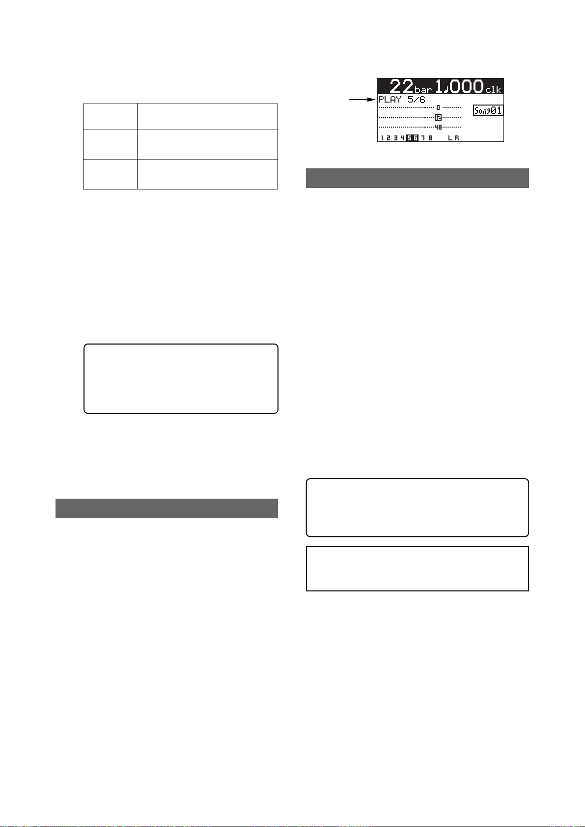
During rehearsal and actual track bouncing,
level meters on the screen show the following
signal levels.
Meters
1 through 4
Playback levels of tracks 1 through
4.
MR-8mkII Owner’s Manual (Track bouncing)
Meters 5/6
Meters
L and R
By raising the [PHONES VOL] control, you can
hear the signals bounced to tracks 5/6.
Use the [5/6] fader to control the monitor output levels, and use the [MASTER] fader to adjust the recording levels of the bounced signals appropriately while checking meters 5/6.
You can apply the delay/reverb to tracks 1
through 4 and the mastering effects to the stereo L and R signals. See "Using effects" on page
57 for details about the delay/reverb and mastering effects.
<Panning control>
You can freely adjust panning for tracks
1 through 4 using the PAN controls.
For example, a guitar to left, a vocal to
center, etc.
5) After finishing rehearsal, press the [STOP] key
to stop the recorder and locate it to the
beginning of the song.
Do not move the controls and faders after
finishing rehearsal.
Recording levels of tracks 5/6.
Monitor output levels of STEREO
OUT (L, R).
Actual track bouncing
After finishing rehearsal, let's carry out actual track bouncing. Make sure that the recorder stops at the beginning of the song.
1) Before carrying out actual track bouncing, make
sure that the bounce mode is selected to
"1-4>5/6".
Checking the bounced signals on tracks 5/6
You can check the bounced signals while the
bounce mode is active.
1) Press the [REWIND] key while holding down the
[STOP] key to locate the recor der to the
beginning of the song.
2) Make sure that the input monitoring mode is
turned off.
3) Press the [PLAY] key to start playback from the
beginning of the song.
4) Use the [5/6] fader to control the playback level
of the bounced signals.
By playing back the recorder while the bounce
mode ("1-4 > 5/6") is active, only tracks 5/6
can be monitored. In this condition, you
cannot monitor playback signals of tracks 1
through 4 even if you raise their faders.
If you want to redo track bouncing, use the
undo function to go back to the condition
before carrying out track bouncing, and try
again.
<Auto punch in/out of track bouncing>
You can bounce only the desired part (between
the IN and OUT points) using the auto punch
in/out function (see page 74).
<Note>:
the [1-4 > 5/6, 1-6 > 7/8] key to exit the bounce
mode.
After track bouncing completes, press
2) Press the [PLAY] key while holding down the
[RECORD] key.
Track bouncing starts with the effect/level
settings made in the rehearsal mode. The mixed
signals are recorded onto tracks 5/6.
3) After track bouncing completes, press the [STOP]
key to stop the recorder.
Stopping the recorder automatically turns off
the input monitoring mode of tracks 5/6, while
the display changes to show the screen below,
prompting you to play back tracks 5/6 for
confirming the result.
69
Page 70
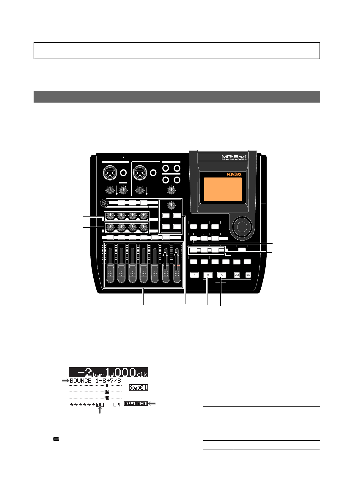
MR-8mkII Owner’s Manual (Track bouncing)
Bouncing tracks 1 thr ough 6 to tracks 7/8
You can bounce tracks 1 through 6 to tracks 7/8.
As described earlier in "Bouncing tracks 1 through 4 to tracks 5/6", you can rehearse track
bouncing as many times as you like before executing actual track bouncing.
Rehearsal of track bouncing
Before executing track bouncing, you can rehearse it. While rehearsing track bouncing, you can
control the playback level, panning and reverb (or delay) send setting of each source track, as
well as apply the mastering effect to the mixed L/R signals. We recommend to make rehearsal
thoroughly until you are satisfied with the sound.
The following assumes that the song you are going to execute track bouncing is loaded.
INPUT A SELECT
INPUT A INPUT B
UNBAL
/GUITAR
BAL
GUITAR
DISTORTION
PEAK
TRIM
LINE
MIN
MIC
MIC
BRIT STACK US METAL 60'S COMBO
4
4
010
LR LR LR
RL
1 2 3 4 5/6 7/8 MASTER
MAX
MIN
BAL
TRIM
PEAK
LINE
MAX
MIC
MIC SIMULATION
TUBECONDENSERDYNAMIC
AMP SIMULATION
100100100
EFFECT SEND
UNBAL
INPUT A
ST OUT
L
R
PHONES
2
1
PHONES VOL
MAX
MIN
EFFECT
REVERB/DELAY TIME
MIN MAX
HALLROOM
RHYTHM
TIME BASE
PLATE DELAY
PAN
REC SELECT
GUIDE
1-4
1-6
MAX
AUTO PUNCH
MIN
PQR6
CONTRAST
SELECT
5/6
7/8
1-8
MNO5JKL4
PLAY MODE
NEW
SONG
LOCATE REC END
LOCATE ABS ZERO
A-B PLAY
STEREO
7/8
WAV FILE
GHI3DEF2ABC1
BRIGHTNATURALPOWERFUL
A / IN B / OUT
BOUNCE
MASTERING
LOCATE
PLAYSTOPRECORD REWIND F FWD
MENU/ENTER
STORE
UNDO/REDO
DELETE+-_0YZ9VWX8STU7
1
4
2,4
1) Use the [1-4 > 5/6, 1-6 > 7/8] key to select the
"1-6 > 7/8" bounce mode.
Selecting this bounce mode automatically arms
tracks 7/8 and changes the monitoring mode
for these tracks to input monitoring mode.
The display looks like this:
Lighting
Lighting
Flashing
2) Raise the [5/6] fader and [MASTER] fader to the
" position. Set all the other track fader s
"
down to the minimum position.
4
5
3
3) Press the [PLAY] key to start playback from the
beginning of the song.
4) While playing back the song, adjust playback levels
of tracks 1 through 6 using the track fader s.
You can also adjust panning for tracks 1
through 4 and apply the reverb or delay to
these tracks, as well as apply the mastering
effect to the mixed sound.
During rehearsal and actual track bouncing,
the track faders and [MASTER] fader control
the following signals.
Faders
1 through 4
Fader 5/6
Playback levels of tracks 1 through
4 for bouncing.
Playback levels of tracks 5/6 for
bouncing.
Fader 7/8
[MASTER]
fader
Monitor levels of tracks 7/8.
Recording master level of tracks 7/8.
70
Page 71
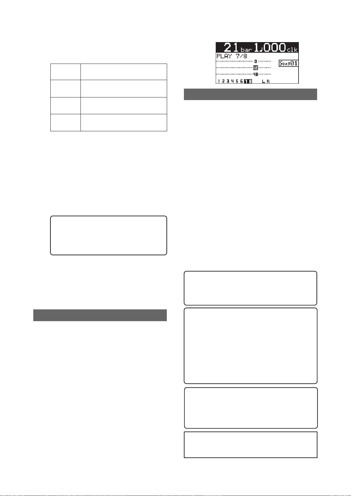
During rehearsal and actual track bouncing,
the level meters on the screen show the following signal levels.
MR-8mkII Owner’s Manual (Track bouncing)
Meters
1 through 4
Meters 5/6
Meters 7/8
Meters L
and R
By raising the [PHONES VOL] control, you can
hear the signals bounced to tracks 7/8.
Use the [7/8] fader to control the monitor output levels, and use the [MASTER] fader to adjust the recording levels of the bounced signals appropriately while checking meters 7/8.
You can apply the delay/reverb to tracks 1
through 4 and the mastering effects to the stereo L and R signals. See "Using effects" on page
59 for details about the delay/reverb and mastering effects.
<Panning control>
You can freely adjust panning for tracks
1 through 4 using the PAN controls. For
example, a guitar to left, a vocal to center, etc.
5) After finishing rehearsal, press the [STOP] key
to stop the recorder and locate it to the
beginning of the song.
Do not move the controls and faders after
finishing rehearsal.
Playback levels of tracks 1 through 4.
Recording levels of tracks 5/6.
Recording levels of tracks 7/8.
Monitor output levels of STEREO
OUT (L, R).
Checking the bounced signals on tracks 7/8
You can check the bounced signals while the
bounce mode is active.
1) Press the [REWIND] key while holding down the
[STOP] key to locate the recor der to the
beginning of the song.
2) Make sure that the input monitoring mode is
turned off.
3) Press the [PLAY] key to start playback from the
beginning of the song.
4) Use the [7/8] fader to control the playback le vel
of the bounced signals.
By playing back the recorder while the bounce
mode ("1-6 > 7/8") is active, only tracks 7/8
can be monitored. In this condition, you can
not monitor playback signals of tracks 1
through 6 even if you raise their faders.
If you want to redo track bouncing, use the
undo function to go back to the condition
before carrying out track bouncing, and try
again.
<Auto punch in/out of track bouncing>
You can bounce only the desired part (between
the IN and OUT points) using the auto punch
in/out function (see page 74).
Actual track bouncing
After finishing rehearsal, let's carry out actual track bouncing. Make sure that the recorder stops at the beginning of the song.
1) Before carrying out actual track bouncing, make
sure that the bounce mode is selected to "1-6>7/8".
2) Press the [PLAY] key while holding down the
[RECORD] key.
Track bouncing starts with the effect/level
settings made in the rehearsal mode. The mixed
signals are recorded onto tracks 7/8.
3) After track bouncing completes, press the [STOP]
key to stop the recorder.
Stopping the recorder automatically turns off
the input monitoring mode of tracks 7/8, while
the display changes to show the screen below,
prompting you to play back tracks 7/8 for
confirming the result.
71
<Exporting bounced data to a PC>
Song data bounced to tracks 7/8 can be exported to a PC (see page 115).
You can use the exported data as a source when
burning an original audio CD using a CD-RW
drive, or use it with a computer's music software. Before exporting song data on tracks 7/
8 to a PC, you must convert the two mono WAV
files on tracks 7/8 to a stereo WAV file (see
page 116).
<Tips>: By connecting an external CD-R/RW
drive to the [USB HOST] connector, you can
burn bounced song data on tracks 7/8 to a CDR/RW disc for making your original audio CD
(see page 123).
<Note>:
After track bouncing completes, press
the [1-4 > 5/6, 1-6 > 7/8] key to exit the bounce
mode.
Page 72
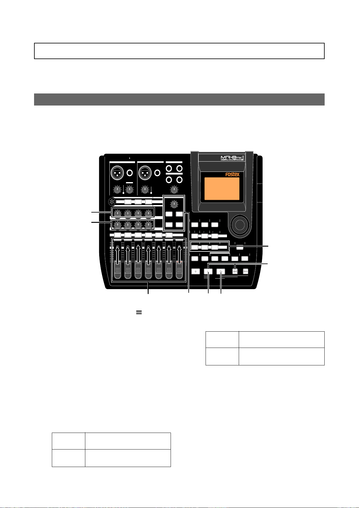
MR-8mkII Owner’s Manual (Track bouncing)
Bouncing tracks 1 thr ough 8 to a new song
You can bounce tracks 1 through 8 to tracks 7/8 of a new song. A new song is automatically
created when executing track bouncing (<Note>: In the “1-8 > NEW SONG” mode, y ou cannot bounce
the desired part of a song by using the track bouncing and auto punch in/out functions together).
Rehearsal of track bouncing
Before executing track bouncing, you can rehearse it. While rehearsing track bouncing, you can
control the playback level, panning and reverb (or delay) send setting of each source track, as
well as apply the mastering effect to the mixed L/R signals. We recommend to make rehearsal
thoroughly until you are satisfied with the sound. The following assumes that the song you are
going to execute track bouncing is loaded.
INPUT A SELECT
INPUT A INPUT B
UNBAL
/GUITAR
BAL
DISTORTION
PEAK
TRIM
LINE
MIN
MIC
MIC
BRIT STACK US METAL 60'S COMBO
3
3
010
RL
LR LR LR
1 2 3 4 5/6 7/8 MASTER
MAX
MIN
BAL
GUITAR
TRIM
PEAK
LINE
MAX
MIC
TUBECONDENSERDYNAMIC
100100100
UNBAL
MIC SIMULATION
INPUT A
AMP SIMULATION
EFFECT SEND
PAN
ST OUT
L
PHONES
1
PHONES VOL
MAX
MIN
EFFECT
REVERB/DELAY TIME
MIN MAX
PLATE DELAY
REC SELECT
R
2
HALLROOM
RHYTHM
TIME BASE
GUIDE
1-4
1-6
MAX
AUTO PUNCH
MIN
PQR6
CONTRAST
SELECT
5/6
STEREO
NEW
7/8
1-8
7/8
WAV FILE
SONG
BOUNCE
MNO5JKL4
PLAY MODE
GHI3DEF2ABC1
BRIGHTNATURALPOWERFUL
A / IN B / OUT
LOCATE REC END
LOCATE ABS ZERO
A-B PLAY
LOCATE
MENU/ENTER
MASTERING
UNDO/REDO
STORE
PLAYSTOPRECORD REWIND F FWD
3
DELETE+-_0YZ9VWX8STU7
4
1,3
1) Raise the [MASTER] fader to the " " position.
Set all the track faders down to the minim um
position.
2) Press the [PLAY] key to start playback from the
beginning of the song.
3) While playing back the song, adjust pla yback
levels of tracks 1 through 8 using the trac k
faders.
You can also adjust panning for tracks 1
through 4 and apply the reverb or delay to
these tracks, as well as apply the mastering
effect to the mixed sound.
During rehearsal and actual track bouncing,
the track faders and [MASTER] fader control
the following signal levels.
Faders
1 through 8
[MASTER]
fader
Playback levels of tracks 1 through
8 for bouncing.
Recording master levels of bouncing.
3
4
2
During rehearsal and actual track bouncing,
the level meters on the screen show the following signal levels.
Meters
1 through 8
Meters
L and R
Playback levels of tracks 1 through
8.
Output levels of STEREO OUT (=
recording levels of bouncing)
By raising the [PHONES VOL] control, you can
hear the bounced signals.
Use the track faders (1 through 8) to control
the track output levels, and use the [MASTER]
fader to adjust the master recording levels of
the bounced signals appropriately while checking meters L/R.
See "Using effects" on page 57 for details about
the delay/reverb and mastering effects.
4) After finishing rehearsal, press the [STOP] key
to stop the recorder and locate it to the
beginning of the song.
Do not move the controls and faders after
finishing rehearsal.
72
Page 73
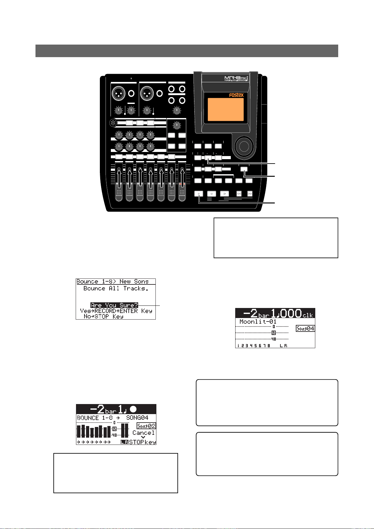
MR-8mkII Owner’s Manual (Track bouncing)
Actual track bouncing
After finishing rehearsal, let's carry out actual track bouncing.
INPUT A SELECT
INPUT A INPUT B
UNBAL
/GUITAR
BAL
PEAK
TRIM
LINE
MIC
MIC
BRIT STACK US METAL 60'S COMBO
010
RL
1 2 3 4 5/6 7/8 MASTER
MAX
MIN
BAL
GUITAR
DISTORTION
TRIM
PEAK
MIN
LINE
MAX
MIC
TUBECONDENSERDYNAMIC
100100100
LR LR LR
UNBAL
MIC SIMULATION
INPUT A
AMP SIMULATION
EFFECT SEND
PAN
ST OUT
L
PHONES
1
PHONES VOL
MAX
MIN
EFFECT
REVERB/DELAY TIME
MIN MAX
PLATE DELAY
REC SELECT
R
2
HALLROOM
RHYTHM
TIME BASE
CONTRAST
GUIDE
SELECT
1-4
5/6
STEREO
NEW
7/8
1-8
1-6
7/8
WAV FILE
SONG
BOUNCE
MNO5JKL4
PLAY MODE
GHI3DEF2ABC1
BRIGHTNATURALPOWERFUL
MASTERING
LOCATE
A / IN B / OUT
PLAYSTOPRECORD REWIND F FWD
LOCATE REC END
LOCATE ABS ZERO
A-B PLAY
MAX
AUTO PUNCH
MIN
PQR6
STORE
MENU/ENTER
UNDO/REDO
DELETE+-_0YZ9VWX8STU7
1
2
2
1) While the recorder is stopped, press the
[1-8 > NEW SONG] key.
The [1-8 > NEW SONG] key lights up and the
display shows the screen below.
If you execute track bouncing, press the
[MENU/ENTER] key while holding down the
[RECORD] key. If you cancel track bouncing,
press the [STOP] key.
flashing
2) Press the [MENU/ENTER] key while holding
down the [RECORD] key.
Track bouncing starts. The mixed (bounced)
signals are recorded to tracks 7/8 of a new
song. The screen example below shows that
tracks 1 through 8 of Song02 (whose name is
“Moonlit”) is now being bounced to tracks 7/8
of the new song (Song04). Meters 1 through 8
show the playback levels of tracks 1 through
8, while the L and R meters shows the
recording levels of tracks 7/8 of Song04.
<Note>:
When you are going to execute track
bouncing, if there is not enough space on
the CompactFlashTM Card or 99 songs already exist on the disk, a warning message
appears and the operation is canceled.
When track bouncing to a new song completes,
the recorder automatically stops and the display shows the home screen of the new song.
The song name of the new song is given by the
name of the original song with “-**” (** is a
two-digit number).
You can check the result by following the procedure described in “Checking the bounced
signals on tracks 7/8” on page 71.
<Exporting bounced data to a PC>
Song data bounced to tracks 7/8 of the new song
can be exported to a PC. You can use the exported
data as a source when burning an original audio
CD using a CD-RW drive, or use it with a computer's
music software (see page 115).
<Note>:
To cancel track bouncing in the
middle, press the [STOP] key. Pressing the
[STOP] key automatically deletes the new
song created in step 2 above and turns off
the bounce mode.
<Chips>: By connecting an external CD-R/RW
drive to the [USB HOST] connector, you can
burn bounced song data on tracks 7/8 to a CDR/RW disc for making your original audio CD
(see page 123).
73
Page 74
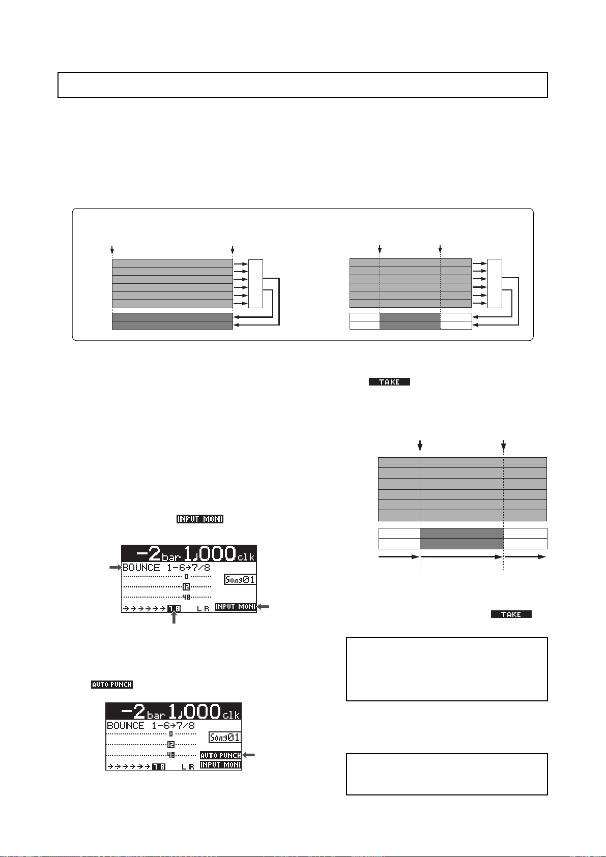
MR-8mkII Owner’s Manual (Track bouncing)
Bouncing the desired part of a song
Typically, bouncing is executed from the beginning to the end of a song, as shown in Figure 1
below. However, you can bounce only the desired part by using the track bouncing and punch
in/out functions together. The following assumes that the song you are going to execute track
bouncing is loaded and you finished rehearsal of track bouncing.
The following procedure shows the example of bouncing the desired part of a song in the "Bounce
1-6 > 7/8" mode (<Caution!>: In the “1-8 > NEW SONG” mode, you cannot bounce the desired part of a
song by using the track bouncing and auto punch in/out functions together).
Typical bouncing (Fig. 1)
ABS ZERO
TRK 1
TRK 2
TRK 3
TRK 4
TRK 5
TRK 6
TRK 7
TRK 8
1) Set the punch-in and punch-out points (see page
56).
By pressing the [PLAY] key while holding down
the [STOP] key, you can play back the part
between the punch-in and punch-out points
(see page 46).
2) Locate the recorder to a position before the
punch-in point.
3) Press the [1-4>5/6, 1-6>7/8] key to set the bounce
mode to "1-6>7/8".
When setting the bounce mode to "1-6>7/8",
tracks 7/8 automatically enter the input
monitor mode and "
home screen.
Lighting
REC END
Mixing
" lights on the
Bouncing the desired part (Fig. 2)
Punch in point
(=LOCATE A point)
TRK 1
TRK 2
TRK 3
TRK 4
TRK 5
TRK 6
TRK 7
TRK 8
5) Press the [RECORD] key while holding down the
[PLAY] key.
The " " icon is shown and the recorder
starts playback. It automatically starts
recording (bouncing) when it reaches the
punch-in point.
TRK 1
TRK 2
TRK 3
TRK 4
TRK 5
TRK 6
TRK 7
TRK 8
Playback
(Input monitor)
Punch out point
(=LOCATE B point)
Punch-in point
(=LOCATE A point)
Recording
(track bouncing)
Mixing
Punch-out point
(=LOCATE B point)
Playback
Lighting
Flashing
4) Press the [AUTO PUNCH] ke y to activate the auto
punch mode.
When the auto punch mode is active,
"
" lights on the home screen.
Lighting
The recorder stops recording (bouncing) at the
punch-out point and returns to playback, while
the auto punch mode exits and "
the screen turns off.
<Note>:
During playback in the operation
above, you cannot monitor the sound. You
can monitor the sound (bounced sound)
only during recording between punch-in and
punch-out points.
6) Press the [STOP] key to stop the recorder.
Check the result by playing back the bounced
tracks, as described earlier.
<Note>:
If you are not satisfied with the result, press the [UNDO/REDO] key to redo the
operation.
74
" in
Page 75

MR-8mkII Owner’s Manual (Rhythm guide function)
Rhythm guide function
The MR-8mkII offers the rhythm guide function, which allows outputting the rhythm guide click during recording.
This chapter describes how to output the rhythm guide, set the
time signature/tempo and create the conductor map.
75
Page 76
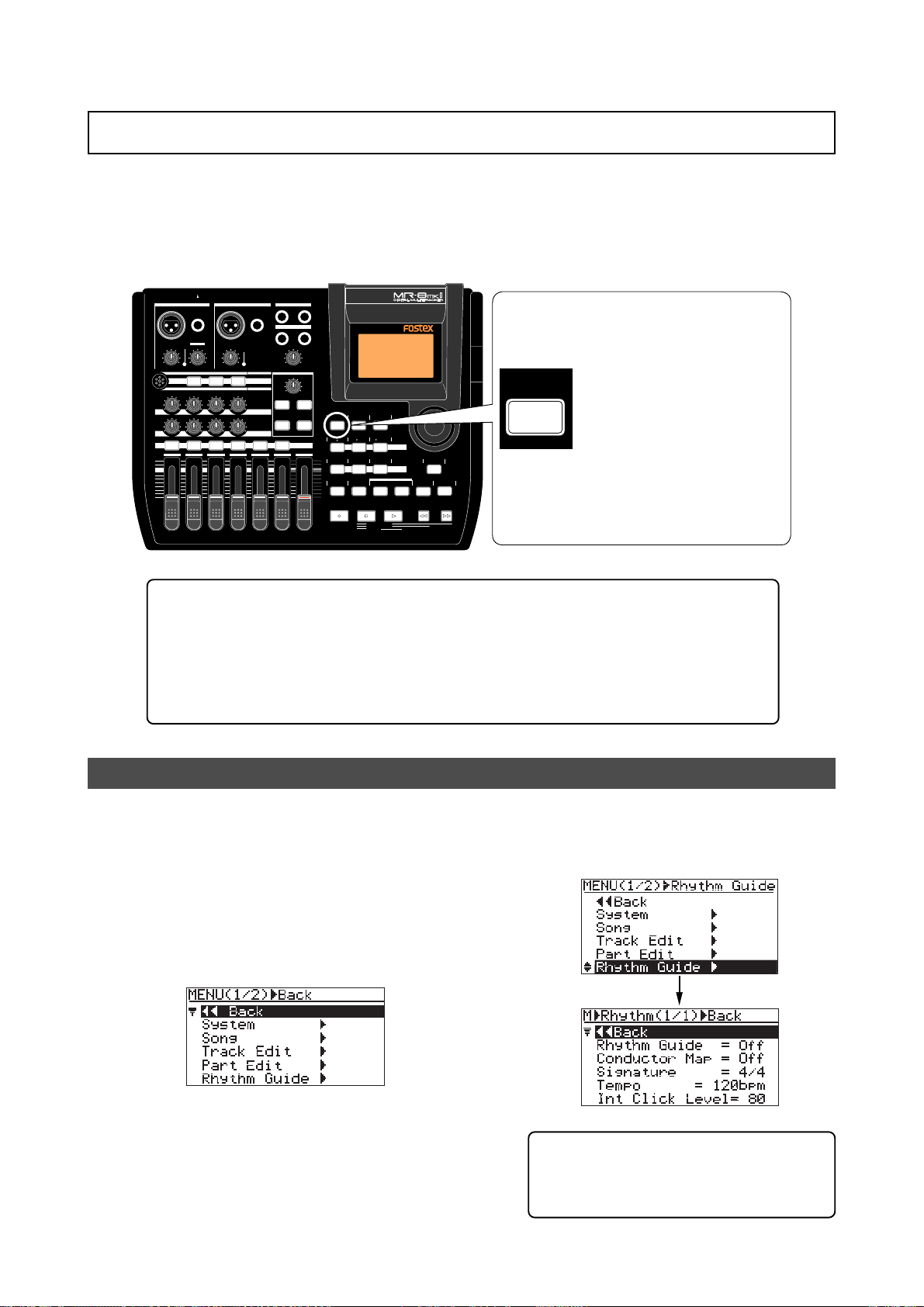
MR-8mkII Owner’s Manual (Rhythm guide function)
Using the rhythm guide function
The MR-8mkII provides the metronome function which can output the rhythm guide click during recording. You can easily output the guide click from the [STEREO OUT] jacks by pressing the
[RHYTHM GUIDE] key on the top panel. Two types of the rhythm guide are available: one has the
constant time signature/tempo throughout a song, while the other has the programmed time
signature/tempo map.
INPUT A SELECT
INPUT A INPUT B
UNBAL
/GUITAR
BAL
PEAK
TRIM
LINE
MIC
MIC
010
RL
1 2 3 4 5/6 7/8 MASTER
MAX
MIN
BAL
GUITAR
DISTORTION
TRIM
MIN
LINE
MAX
MIC
BRIT STACK US METAL 60'S COMBO
100100100
LR LR LR
TUBECONDENSERDYNAMIC
PEAK
UNBAL
MIC SIMULATION
INPUT A
AMP SIMULATION
EFFECT SEND
PAN
ST OUT
L
PHONES
1
PHONES VOL
MIN
EFFECT
REVERB/DELAY TIME
MIN MAX
PLATE DELAY
REC SELECT
R
2
T o output the rhythm guide click,
turn on the [RHYTHM GUIDE]
key. By default, the guide click
MAX
RHYTHM
HALLROOM
RHYTHM
TIME BASE
CONTRAST
GUIDE
SELECT
1-4
5/6
STEREO
NEW
7/8
1-8
1-6
7/8
WAV FILE
SONG
BOUNCE
MAX
AUTO PUNCH
MIN
GHI3DEF2ABC1
BRIGHTNATURALPOWERFUL
MNO5JKL4
PLAY MODE
A / IN B / OUT
PQR6
LOCATE REC END
LOCATE ABS ZERO
A-B PLAY
MENU/ENTER
MASTERING
LOCATE
STORE
PLAYSTOPRECORD REWIND F FWD
UNDO/REDO
DELETE+-_0YZ9VWX8STU7
GUIDE
is output at time signature=4/4,
tempo=120.
Y ou can output the rhythm guide
click according to the desired
constant time signature and
tempo, as well as the programmed rhythm guide click
based on the conductor map.
When recording starts, the MR-8mkII simultaneously starts feeding the rhythm guide
click from the [STEREO OUT (L, R)] jacks at the selected level (the default is 80). Note
that the rhythm guide click is not output during track bouncing. The output level of
the rhythm guide click is shown on the L and R level meters.
Note that you can monitor the rhythm guide click via headphones or (a) monitor
speaker(s). You cannot record the rhythm guide click to any MR-8mkII track(s). If you
do not want to output the rhythm guide click, turn off the [RHYTHM GUIDE] key.
Setting the time signature and tempo
You can set the default rhythm guide (time signature: 4/4, tempo: 120), output level, etc. using
the "Rhythm Guide" menu in the menu mode.
1) While the recorder is stopped, press the
[MENU/ENTER] key to enter the menu mode.
The display now shows the first page of the
menu selection screen, where "<< Back" is
highlighted initially (selecting "<< Back"
returns to the previous screen).
2) Rotate the JOG dial to select "Rhythm Guide",
and press the [MENU/ENTER] key.
The display now shows the screen for setting
the rhythm guide, where "<< Back" is
highlighted.
<Tip>: While the home screen is shown and
the recorder is stopped, long press of the
[RHYTHM GUIDE] key directly brings up the
screen for setting the rhythm guide.
76
Page 77
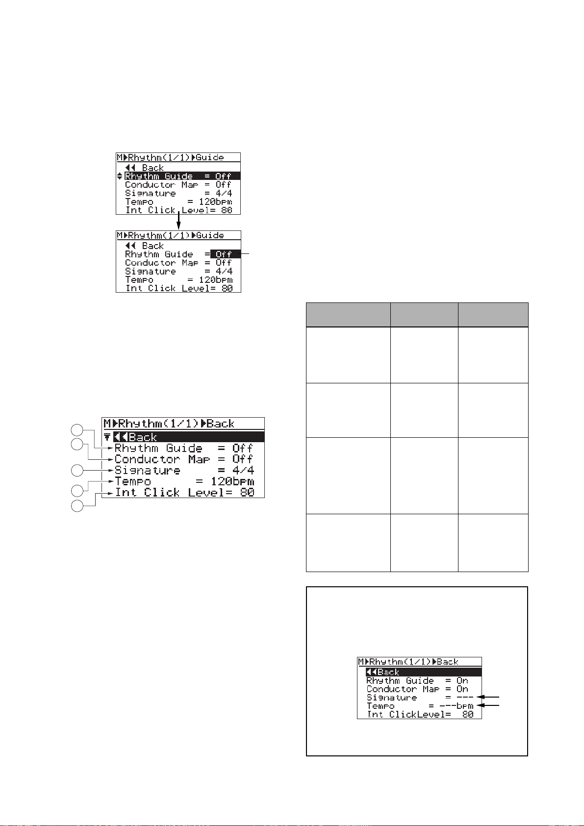
MR-8mkII Owner’s Manual (Rhythm guide function)
3) Rotate the JOG dial to select the desired item,
and press the [MENU/ENTER] key.
The current setting of the selected item starts
flashing. On the screen examples below, the
"Rhythm Guide" item is highlighted (see the
upper screen) and the [MENU/ENTER] key is
pressed (see the lower screen).
flashing
4) Rotate the JOG dial to select the desired option,
and press the [MENU/ENTER] key.
The selected option (in the example above,
"On" or "Off") is confirmed and the display
returns to the previous screen.
You can make setting for each item similarly.
The rhythm guide setting screen has the following
items.
1
2
3
4
5
4. Tempo: T empo setting
The default is "120bpm". You can select between
30 and 250 bpm. The setting here is effective from
the beginning to the end of the song when the
"Conductor Map" item is set to "Off" (i.e. the same
tempo all through the song).
When the "Conductor Map" item is set to "On",
the setting here is ineffective. See the table on the
below for details.
5. Int ClickLevel: Internal click output level
The default is "80". You can set it between 0 and
99.
To exit the menu mode, press the [STOP] key, or select "<< Back" and press the [MENU/ENTER] key repeatedly.
The table below shows how the "Rhythm Guide" and
"Conductor Map" item settings affect the conditions
of rhythm guide output and bar/beat indication.
On/off conditions
Rhythm Guide: Off
Conductor Map: Off
Rhythm Guide: Off
Conductor Map: On
Rhythm guide
No output
No output
Bar/beat
indication
The "Signature"
and "Tempo"
item settings are
effective.
The conductor
map is effective.
Output:
Rhythm Guide: On
Conductor Map: Off
The tempo and
time signature
setting on this
screen is effec-
The "Signature"
and "Tempo"
item settings are
effective.
tive.
1. Rhythm Guide: On/off selection of the rhythm guide
The setting you make here is reflected to the
[RHYTHM GUIDE] key (the key is lit when ON, while
it is unlit when OFF). Conversely, when you turn
on or off the rhythm guide using the
[RHYTHM GUIDE] key, the status is reflected to
this screen. See the table on the right for details.
2. Conductor Map: On/off selection of the conductor map
This item enables or disables the conductor map
(see "Conductor map" described later).
The default is "Off". See the table on the right for
details.
3. Signature: Time signature setting
The default is "4/4". You can select from among
1/4 through 5/4 and 1/8 through 8/8.
The setting here is effective from the beginning to
the end of the song when the "Conductor Map"
item is set to "Off" (i.e. the same time signature
all through the song). When the "Conductor Map"
item is set to "On", the setting here is ineffective.
See the table on the right for details.
Rhythm Guide: On
Conductor Map: On
<Note>:
the “Signature” and “Tempo” fields show “- - -” as
below. This indicates that the signature and tempo
values set on this screen are ineffective, while the
conductor map setting is effective.
See the next page for details about how to set the
conductor map.
77
Output:
The conductor
map setting is
The conductor
map is effective.
effective.
When “Conductor Map” is set to “On”,
Page 78
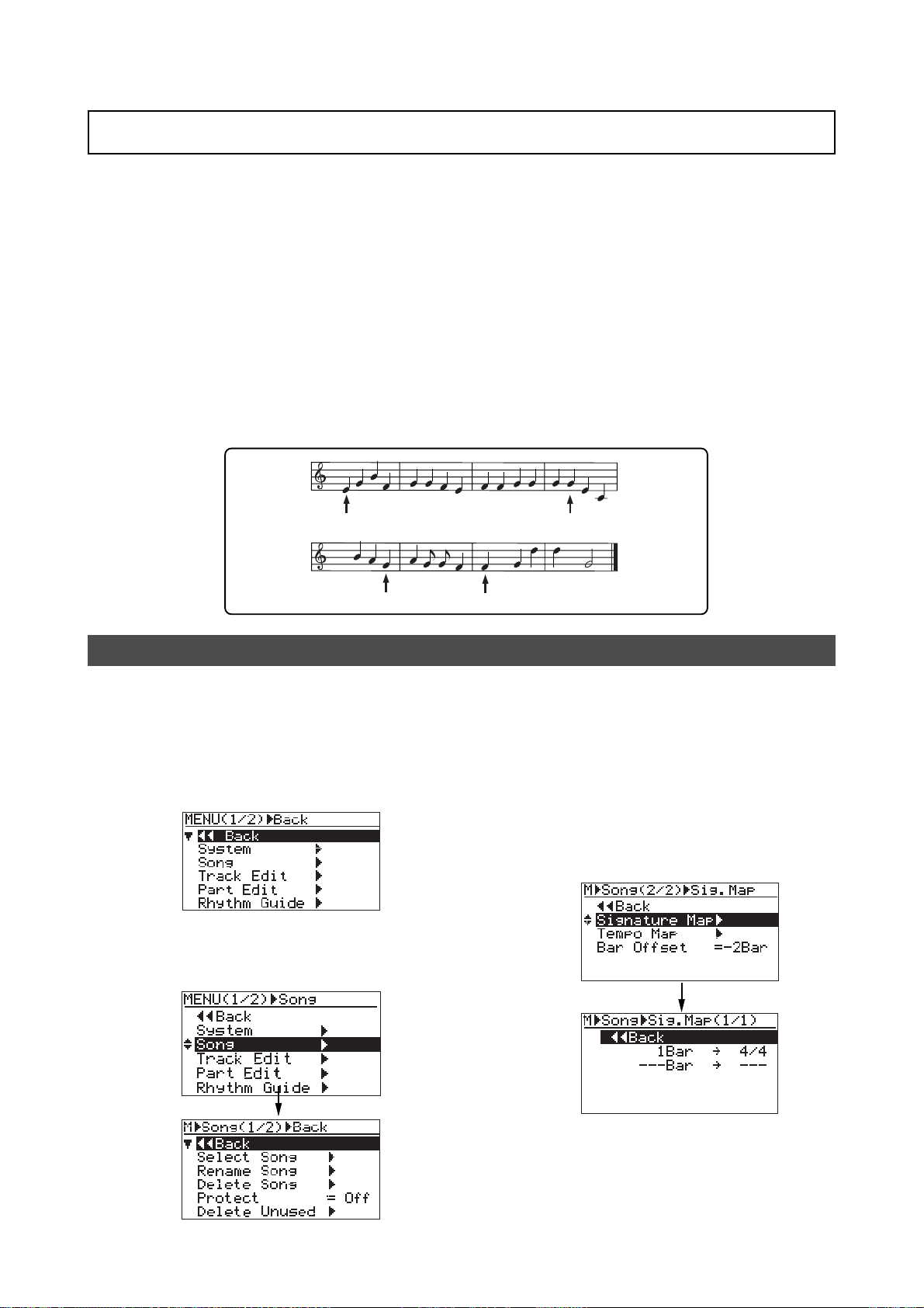
MR-8mkII Owner’s Manual (Rhythm guide function)
Creating the conductor map
The MR-8mkII can output the rhythm guide click which follows the "conductor map" during
recording. It can also output MIDI clock and song position pointer which follows the "conductor
map" from the [MIDI OUT] connector.
The conductor map consists of the time signature map and tempo map. You can add "events" to
each map. Each event specifies the time signature or tempo, as well as the position from which
the specified time signature or tempo is effective. The time signature or tempo specified by each
event is effective until the next event in the map appears.
For example, if the time signature map has two events -- one sets "4/4" at the first bar 1, while
the other sets "2/4" at the third bar --, the song is played in 4/4 from bar 1 to 2, and played in
2/4 from bar 3 to the end.
For another example, if the tempo map has two events -- one sets "120" at the first bar 1/first
beat while the other sets "90" at bar 12/beat 2 --, the song is played at 120 bpm from bar 1 to bar
12/beat 1, while it is played at 90 from bar 12/beat 2 to the end.
4
4
120
3
4
90
Setting the signature map
1) While the recorder is stopped, press the
[MENU/ENTER] key to enter the menu mode.
The display now shows the first page of the
menu selection screen, where "<< Back" is high
lighted initially (selecting "<< Back" returns to
the previous screen). You can also return to
the previous screen by pressing the [REWIND]
key.
2) Rotate the JOG dial to select "Song", and press
the [MENU/ENTER] key.
The display now shows the song editing screen,
where "<< Back" is highlighted.
180
120
3) Rotate the JOG dial to select "Signature Map"
on the second page, and press the
[MENU/ENTER] key.
The display shows the signature map screen
on which the current time signature events are
listed. Each event specifies the bar number and
time signature. By default, "1Bar -> 4/4" and
"---Bar -> ---" are listed. In this condition, the
song is played in 4/4 from the beginning to
the end.
"---Bar -> ---" is used to create a new event.
78
The procedure example below shows how to
add the following events to the signature map.
Page 79
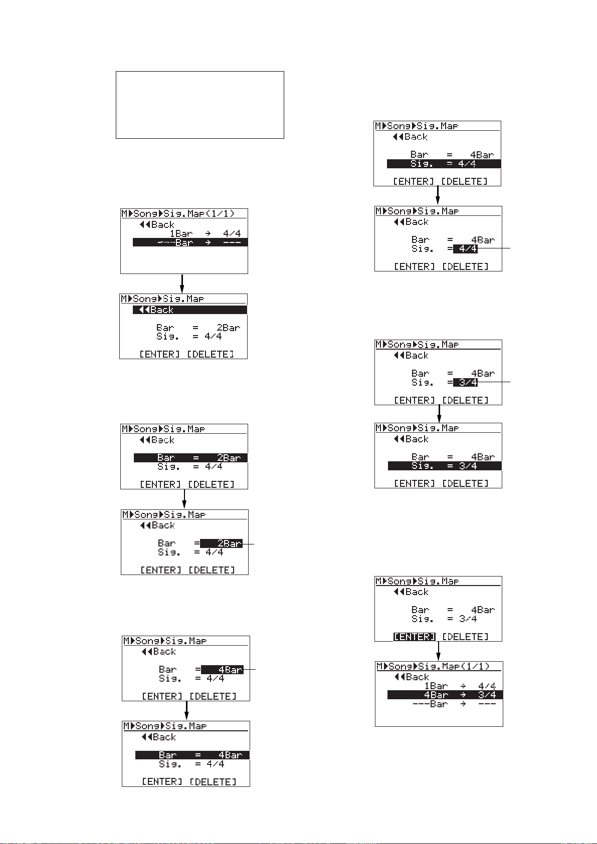
MR-8mkII Owner’s Manual (Rhythm guide function)
Bar 1 through bar 3: 4/4
Bar 4 through bar 7: 3/4
Bar 8 through bar 11: 4/4
Bar 12 through bar 15: 5/8
Bar 16 through the last bar: 3/4
4) Rotate the JOG dial to select "---Bar -> ---", and
press the [MENU/ENTER] key.
The display now shows the screen for setting
the new time signature event, where "<< Back"
is highlighted.
7) Rotate the JOG dial to select "Sig. = 4/4", and
press the [MENU/ENTER] key.
"4/4" starts flashing and you can now set the
time signature.
flashing
8) Rotate the JOG dial to select the desired time
signature, and press the [MENU/ENTER] key.
In this procedure example, enter "3/4".
The display returns to the previous screen.
5) Rotate the JOG dial to select "Bar = 2Bar", and
press the [MENU/ENTER] key.
"2Bar" starts flashing and you can now set the
bar number.
flashing
6) Rotate the JOG dial to enter the desired bar
number , and press the [MENU/ENTER] key.
In this procedure example, enter "4Bar". The
display returns to the previous screen.
flashing
flashing
9) Rotate the JOG dial to select "[ENTER]" at the
bottom, and press the [MENU/ENTER] key.
The new time signature event is set and the
display shows the screen as below.
In this condition, the song is played in 4/4 from
bar 1 to bar 3 and in 3/4 from bar 4.
79
Repeat steps 5 through 9 until creating all necessary events.
Page 80
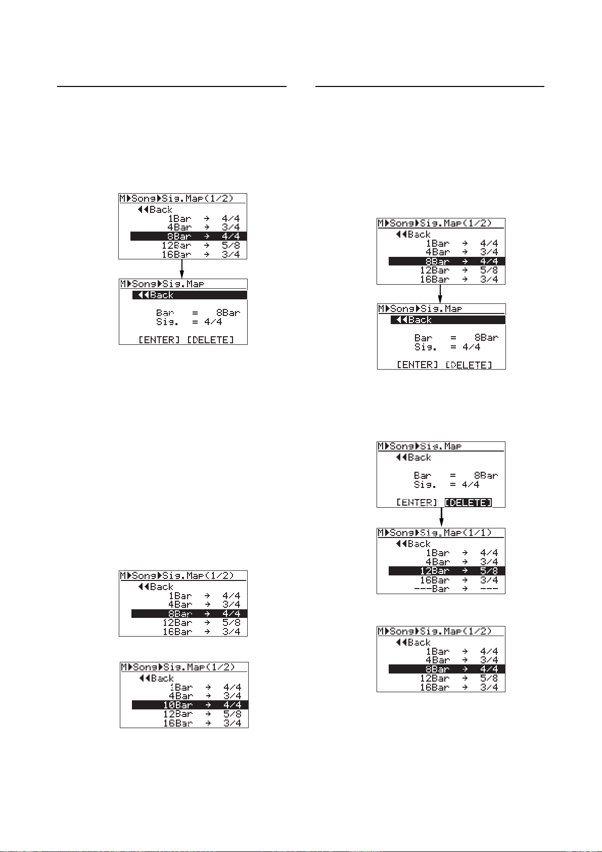
MR-8mkII Owner’s Manual (Rhythm guide function)
• Editing a time signature event
You can edit a time signature event.
1) On the time signature map screen, rotate the
JOG dial to select the event you want to edit, and
press the [MENU/ENTER] key.
As with the description on the previous page, the
display now shows the screen for setting the event.
For example, let's select "8Bar -> 4/4".
2) To change the bar n umber , rotate the JOG dial to
select "Bar = 8Bar", and press the
[MENU/ENTER] key.
T o change the time signature, r otate the JOG dial
to select "Sig. = 4/4", and press the
[MENU/ENTER] key.
As with the procedure described on the
previous page, you can now set the bar
number or time signature.
• Deleting an unnecessary time signature event
You can delete an unnecessary time signature
event.
1) On the time signature map screen, rotate the
JOG dial to select the event you want to delete,
and press the [MENU/ENTER] key.
As with the description on the previous page,
the display now shows the screen for setting
the event.
For example, let's select "8Bar -> 4/4".
2) Rotate the JOG dial to select "[DELETE]" at the
bottom, and press the [MENU/ENTER] key.
The event is immediately deleted and the
display returns to the signature map screen.
3) Rotate the JOG dial to edit the value, and press
the [MENU/ENTER] key.
In this procedure example, enter "10" for the
bar number.
4) Rotate the JOG dial to select "[ENTER]" at the
bottom, and press the [MENU/ENTER] key.
The editing is confirmed and the display
returns to the signature map screen.
<Before editing>
<After editing>
<After deleting>
<Before deleting>
T o e xit the men u mode, press the [STOP] key,
T o e xit the men u mode, press the [STOP] key,
80
Page 81
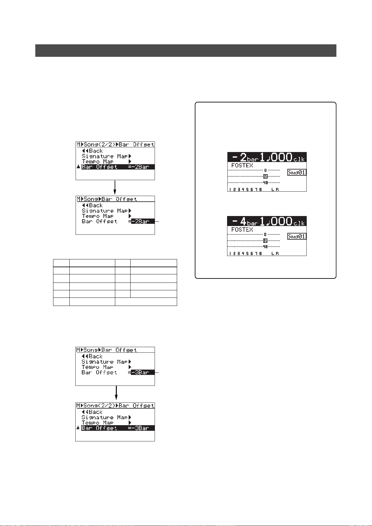
MR-8mkII Owner’s Manual (Rhythm guide function)
Editing the bar offset
By default, the bar/beat value at the beginning (ABS ZERO) of the song is set to "bar -2/beat 1".
This offset (the bar/beat value at ABS ZERO) is called "bar offset". You can change the default bar
offset to the desired value.
1) On the second page of the song editing menu
screen, highlight "Bar Offset" and press the
[MENU/ENTER] key.
The current offset value (by default, "-2Bar")
starts flashing.
flashing
The table below shows the available offset values.
Option
-8Bar
-7Bar
-6Bar
-5Bar
-4Bar
ABS Zero= bar -8
ABS Zero= bar -7
ABS Zero = bar -6
ABS Zero= bar -5
ABS Zero= bar -4
OptionMeaning Meaning
-3Bar
ABS Zero= bar -3
-2Bar
ABS Zero= bar -2
-1Bar
ABS Zero= bar -1
0Bar
ABS Zero= bar 1
You can see the bar offset value on the home
screen when the recorder is at the beginning
of the song (ABS 0).
The screen example below shows the home
screen when the bar offset is set to “-4 bars”.
The default home screen (bar offset = -2 bars).
The home screen when the
bar offset is set to “-4 bars”.
2) Rotate the JOG dial to select the desired offset
value, and press the [MENU/ENTER] ke y.
The selected offset value is confirmed, while
the display returns to the previous screen.
flashing
T o exit the men u mode, press the [STOP] key,
81
Page 82
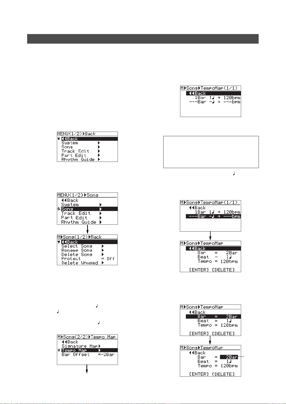
MR-8mkII Owner’s Manual (Rhythm guide function)
Setting the tempo map
After setting the time signature map, you have to create the tempo map by adding the necessary
tempo event(s). Like a time signature event, a tempo event specifies the tempo at the tempo
changing point. Each tempo specified by a tempo event is effective until the next event appears.
For example, you can set the tempo to 120 at the third beat in bar 4, and set to 90 at the second
beat in bar 12, etc.
1) While the recorder is stopped, press the
[MENU/ENTER] key to enter the menu mode.
The display now shows the first page of the
menu selection screen, where "<< Back" is
highlighted initially (selecting "<< Back"
returns to the previous screen). You can also
return to the previous screen by pressing the
[REWIND] key.
2) Rotate the JOG dial to select "Song", and press
the [MENU/ENTER] key.
The display now shows the song editing screen,
where "<< Back" is highlighted.
The procedure example below shows how to
add the following tempo events to the tempo
map.
Bar 1/beat 1: 120 bpm
Bar 4/beat 2: 180 bpm
Bar 8/beat 3: 90 bpm
Bar 12/beat 1: 120 bpm
Bar 16/beat 4: 250 bpm
4) Rotate the JOG dial to select "---Bar - -> ---bpm",
and press the [MENU/ENTER] key .
The display now shows the screen for setting
the new tempo event, where "<< Back" is
highlighted.
3) Rotate the JOG dial to select "Tempo Map" on
the second page, and press the [MENU/ENTER]
key.
The display shows the tempo map screen on
which the current tempo events are listed.
Each event specifies the bar/beat position and
tempo. By default, "1Bar 1
"---Bar condition, the song starts in 120 bpm and there
is no tempo change. "---Bar to create a new tempo event.
-> ---bpm" are listed. In this
-> 120 bpm" and
-> ---bpm" is used
5) Rotate the JOG dial to select "Bar = 2Bar", and press
the [MENU/ENTER] key .
"2Bar" starts flashing and you can now set the
bar number. You can enter the bar number
between 1 and 999.
flashing
82
Page 83
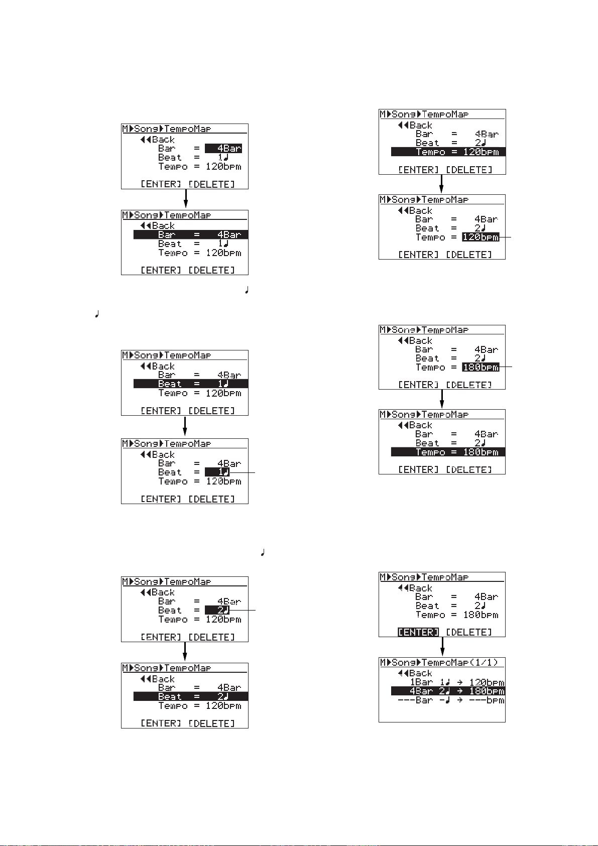
MR-8mkII Owner’s Manual (Rhythm guide function)
6) Rotate the JOG dial to enter the desired bar
number , and press the [MENU/ENTER] key.
In this procedure example, enter "4Bar".
The display returns to the previous screen.
7) Rotate the JOG dial to select "Beat = 1 ", and
press the [MENU/ENTER] key.
"1 " starts flashing and you can now set the
beat number. You can enter the beat number
between 1 and 8.
"120bpm" starts flashing and you can now set
the tempo. You can enter the tempo between
30 and 250.
flashing
10) Rotate the JOG dial to enter the desired tempo,
and press the [MENU/ENTER] key.
In this procedure example, enter "180bpm".
The display returns to the previous screen.
flashing
flashing
8) Rotate the JOG dial to enter the desired beat
number , and press the [MENU/ENTER] key.
In this procedure example, let's enter "2 ".
The display returns to the previous screen.
flashing
9) Rotate the JOG dial to select "Tempo = 120bpm",
and press the [MENU/ENTER] key.
11) Rotate the JOG dial to select "[ENTER]" at the
bottom, and press the [MENU/ENTER] key.
The new tempo event is set and the display
shows the screen as below. In this condition,
the song is played in 120 bpm from the
beginning to bar 4/beat 1 and in 180 from bar
4/beat 2 to the end.
Repeat steps 4 through 11 until creating all
necessary tempo events.
83
Page 84
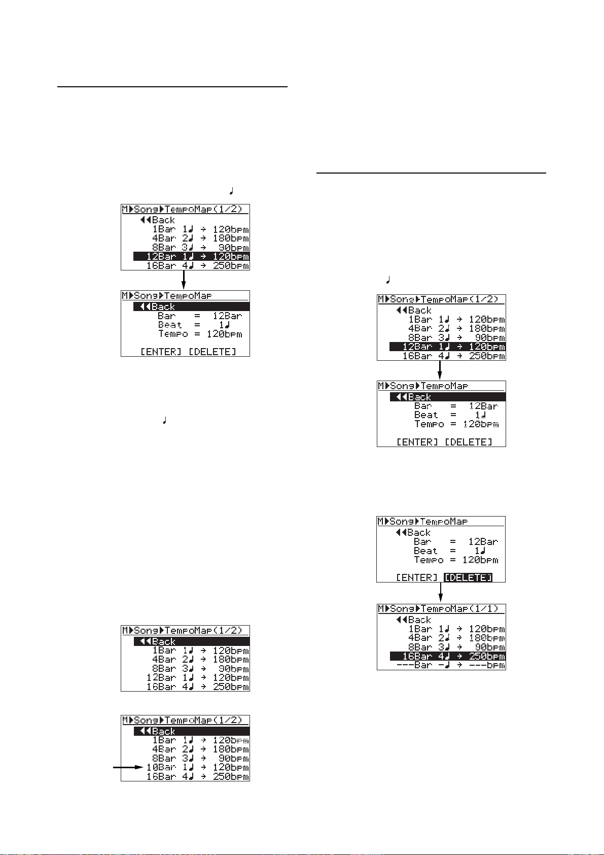
MR-8mkII Owner’s Manual (Rhythm guide function)
• Editing a tempo event
You can edit a tempo event.
1) On the tempo map screen, rotate the JOG dial to
select the event you want to edit, and press the
[MENU/ENTER] key.
As with the description on the previous page,
the display now shows the screen for setting
the event.
For example, let's select "12Bar 1
2) To change the bar n umber , rotate the JOG dial to
select "Bar = 12Bar", and press the
[MENU/ENTER] key.
T o change the beat n umber, rotate the JOG dial
to select "Beat = 1
[MENU/ENTER] key.
T o c hange the tempo, rotate the JOG dial to
select "Tempo = 120bpm", and press the
[MENU/ENTER] key.
As with the procedure described on the
previous page, you can now set the bar
number, beat number or tempo.
", and press the
-> 120bpm".
To exit the menu mode, press the [STOP] key,
or select "<< Back" and press the [MENU/ENTER] key repeatedly.
• Deleting an unnecessary tempo event
You can delete an unnecessary tempo event.
1) On the tempo map screen, rotate the JOG dial to
select the event you want to delete, and press
the [MENU/ENTER] key .
As with the description on the previous page,
the display now shows the screen for setting
the event. For example, let's select
"12Bar 1
2) Rotate the JOG dial to select "[DELETE]" at the
bottom, and press the [MENU/ENTER] key.
The event is immediately deleted and the
display returns to the tempo map screen.
->120bpm".
3) Rotate the JOG dial to edit the value, and press
the [MENU/ENTER] key.
In this procedure example, let's enter "10" for
the bar number.
4) Rotate the JOG dial to select "[ENTER]" at the
bottom, and press the [MENU/ENTER] key.
The editing is confirmed and the display
returns to the tempo map screen.
<Before editing>
<After editing>
<After deleting>
To exit the menu mode, press the [STOP] key,
or select "<< Back" and press the [MENU/ENTER] key repeatedly.
84
Page 85

MR-8mkII Owner’s Manual (MIDI synchronization)
MIDI synchr onization
By connecting the external MIDI devices (such as a sequencer, sound
module, computer, etc.) via the [MIDI OUT] connector of the MR8mkII, you can make powerful recording.
For example, by synchronizing a sequencer with the MR-8mkII during playback, you can mix down signals (such as a vocal, guitar,
etc.) recorded on the MR-8mkII tracks and audio from a sound module.
You can synchronize MIDI with the MR-8mkII by connecting a MIDI
device to the [MIDI OUT] connector on the MR-8mkII and sending
out MTC (MIDI time code) or MIDI clock (with Song Position Pointer)
from the MR-8mkII.
85
Page 86
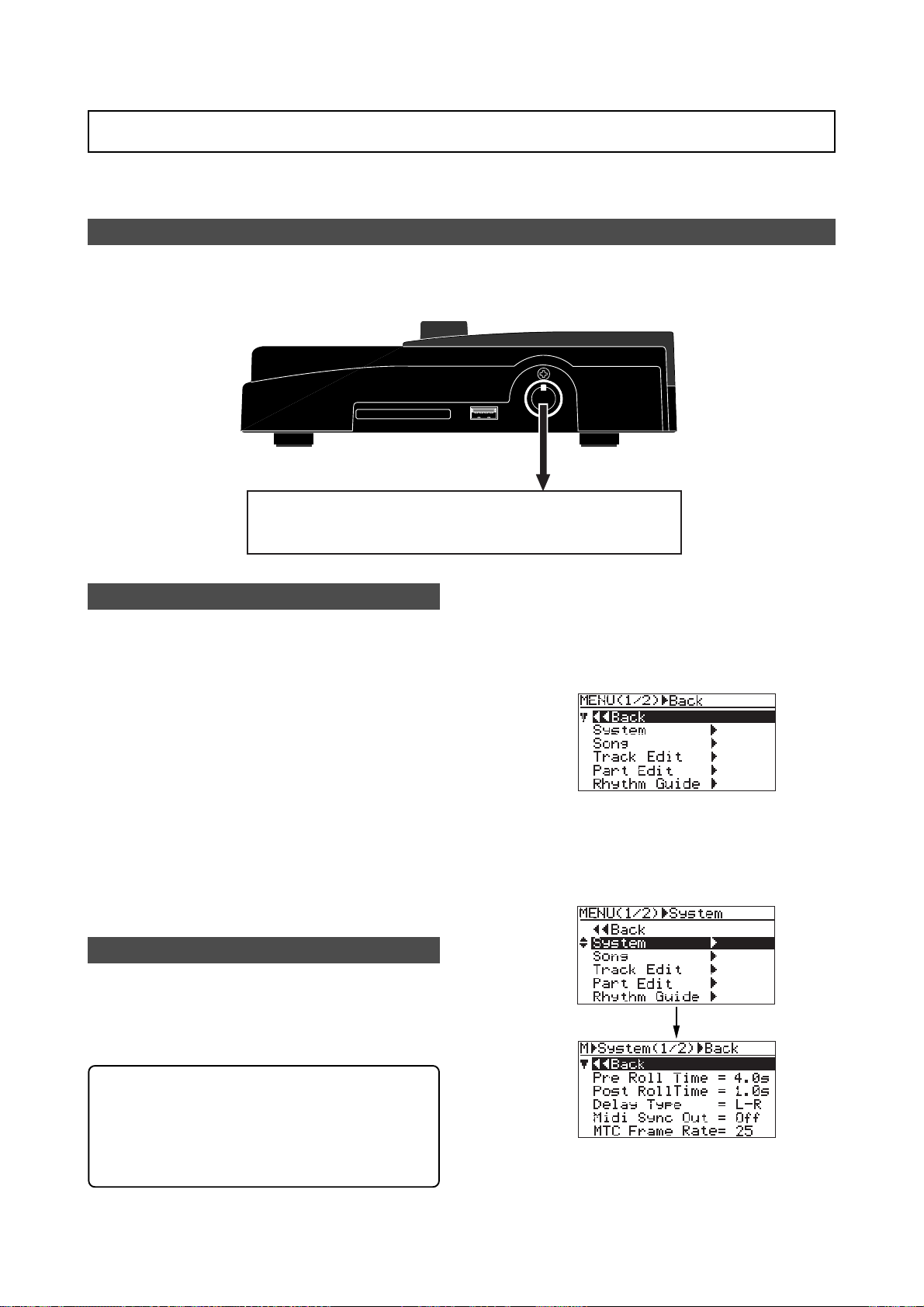
MR-8mkII Owner’s Manual (MIDI synchronization)
Synchronization using MTC
The following describes how to synchronize a sequencer to the MR-8mkII which supports MTC
(MIDI Time code).
Connection
Connect the [MIDI OUT] connector of the MR-8mkII to the [MIDI IN] connector of an external
MIDI sequencer using a MIDI cable. (Note that no MIDI cable is supplied with the MR-8mkII.
Use a commercially available MIDI cable.)
MIDI OUTUSB HOSTCOMPACTFLASH CARD
MIDI IN
MIDI sequencer, etc.
Settings of the MR-8mkII and MIDI sequencer
1) Set the "Midi Sync Out" item in the "System"
menu of the menu mode to "MTC" and the "MTC
Frame Rate" to an appropriate frame rate.
See "MIDI sync/MTC frame rate settings"
described below for details.
2) Enable the external MIDI sequencer to
synchronize to MTC.
See the operation manual of the sequencer for
details.
3) Press the [PLAY] key of the MR-8mkII to start
playback.
The sequencer automatically starts playback
while synchronizing to the MR-8mkII
MIDI sync/MTC frame rate settings
While the MR-8mkII is stopped, you can set
the reference of MIDI synchronization to
"MTC" and the MTC frame rate appropriately
to match the sequencer.
1) While the recorder is stopped, press the
[MENU/ENTER] key to enter the menu mode.
The display now shows the first page of the
menu selection screen, where "<< Back" is
highlighted initially (selecting "<< Back"
returns to the previous screen).
2) Rotate the JOG dial to select "System", and press
the [MENU/ENTER] key .
The display now shows the first page of the
system menu screen, where "<< BACK" is
highlighted initially.
<MTC start time>
The MTC from the MR-8mkII has one hour offset to the ABS time (the offset value is fixed).
Therefore, when you start the MR-8mkII from
the beginning of a song (ABS ZERO), the MTC
starts from "01h 00m 00s 00f".
3) Rotate the JOG dial to select "Midi Sync Out",
and press the [MENU/ENTER] key.
86
Page 87
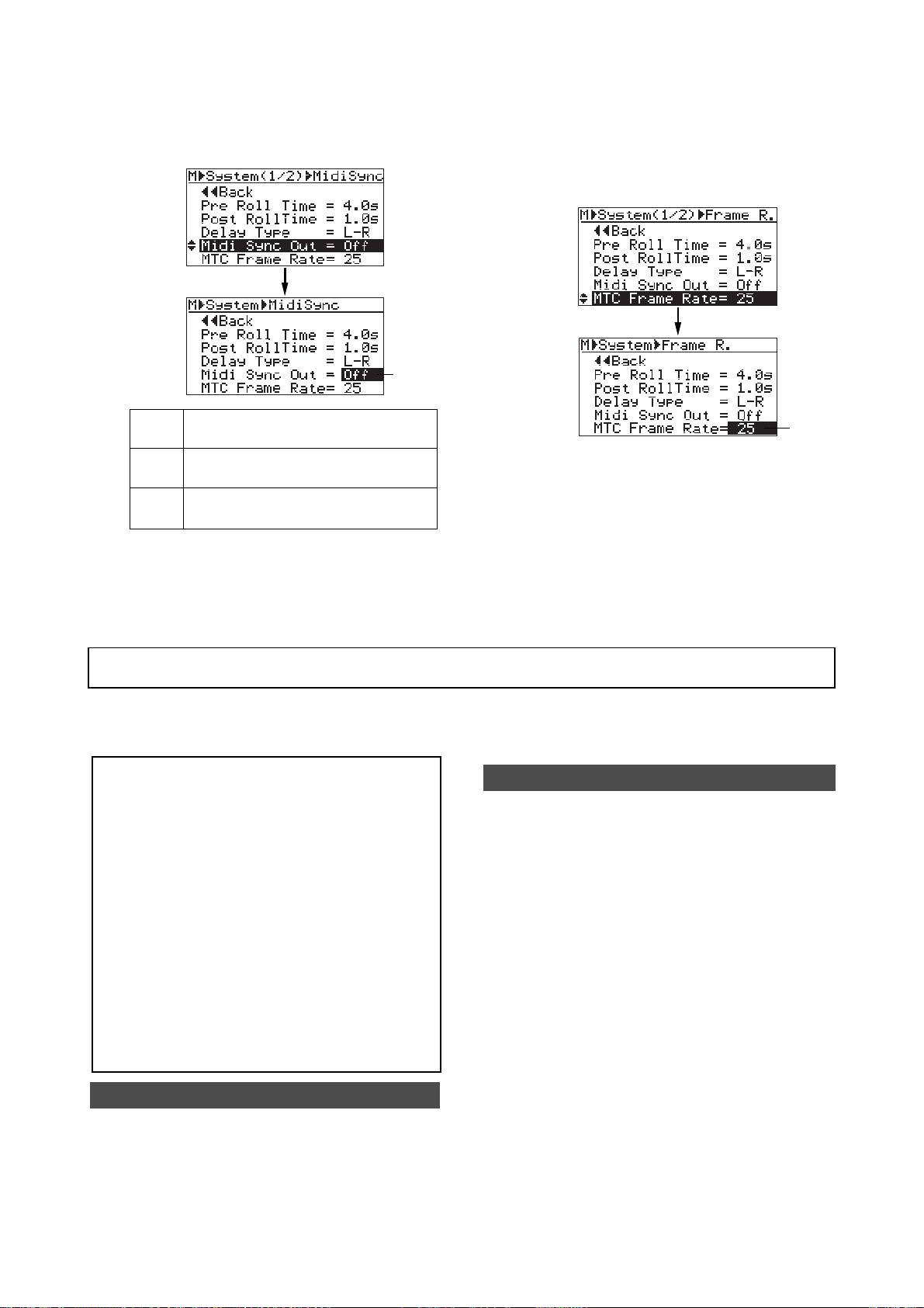
MR-8mkII Owner’s Manual (MIDI synchronization)
The current option (the default is "Off")
flashes. You can now select the desired option
(the available options are Off, CLK and MTC).
flashing
No signal is output from the [MIDI OUT]
Off
connector. This is the default.
MIDI clock with Song Position Pointer is
CLK
output from the [MIDI OUT] connector.
MTC
4) Rotate the JOG dial to select "MTC", and press
the [MENU/ENTER] key.
"Midi Sync Out" is now set to "MTC", while
"Midi Sync Out" is highlighted on the screen.
MIDI time code is output from the [MIDI
OUT] connector.
5) Rotate the JOG dial to select "MTC Frame Rate",
and press the [MENU/ENTER] key.
The current option (the default is "25") flashes.
You can now select the desired frame rate (the
options are "24", "25", "30nd" and "30df").
flashing
6) Rotate the JOG dial to select the desired frame
rate, and press the [MENU/ENTER] key.
The selected frame rate is now effective, while
"MTC Frame Rate" is highlighted on the screen.
7) Press the [STOP] key to exit the menu mode.
Synchronization using MIDI c loc k
The following describes how to synchronize a sequencer to the MR-8mkII using MIDI clock.
Use this method if the sequencer does not support MTC (MIDI Time code)
<Notes>
• To synchronize a sequencer to the MR-8mkII
using MIDI clock, you have to make the
signature/tempo map in the MR-8mkII.
The MIDI clock is output based on the
signature/tempo map in the MR-8mkII.
When you record MIDI sounds, synchronize the
sequencer to the MIDI clock fed from the
MR-8mkII.
• Generally, a sequencer supporting MIDI song
position pointer as well as MIDI clock can
synchronize to the MR-8mkII when you start
playback of the MR-8mkII from the middle of
a song. It locates the current song position and
chases the MR-8mkII. However, note that some
sequencer may not synchronize to the
MR-8mkII.
Connection
As with the connection for MTC synchronization, connect the [MIDI OUT] connector of the
MR-8mkII to the [MIDI IN] connector of an
external MIDI sequencer using a MIDI cable.
Settings of the MR-8mkII and MIDI sequencer
1) Set the "Midi Sync Out" item in the "System"
menu of the menu mode to "Clk".
See "MIDI sync/MTC frame rate settings"
described above about how to set.
2) Create the signature/tempo map by setting
"Signature Map" and "Tempo Map" items in the
"Song" menu of the menu mode appropriately.
See "Using the rhythm guide function" on page
76 for details about how to set these items.
3) Enable the external MIDI sequencer to
synchronize to MIDI clock.
See the operation manual of the sequencer for
details.
4) Press the [PLAY] key of the MR-8mkII to start
playback.
The sequencer also starts playback in sync with
the MR-8mkII.
87
Page 88

MR-8mkII Owner’s Manual (MIDI synchronization)
88
Page 89

MR-8mkII Owner’s Manual (Song management)
Song management
This chapter explains the following five operation procedures for
song management.
1) Selecting the desired song.
2) Editing a song name.
3) Deleting an unnecessary song.
4) Protecting a song.
5) Deleting an unused WAV file in a song.
<Notes>:
level or directly exit the menu mode by the following operations.
(1) Select “<< Back” on a menu screen and press the [MENU/ENTER] key .
(2) Press the [REWIND] key .
(3) Press the [STOP] key.
While a menu screen is shown, you can go up the menu screen
The display returns to the previous (upper level) screen. Repeating
this operation finally exits the menu mode.
The display returns to the previous (upper level) screen.
Repeating this operation finally exits the menu mode.
The menu mode exits and the display shows the home screen.
89
Page 90
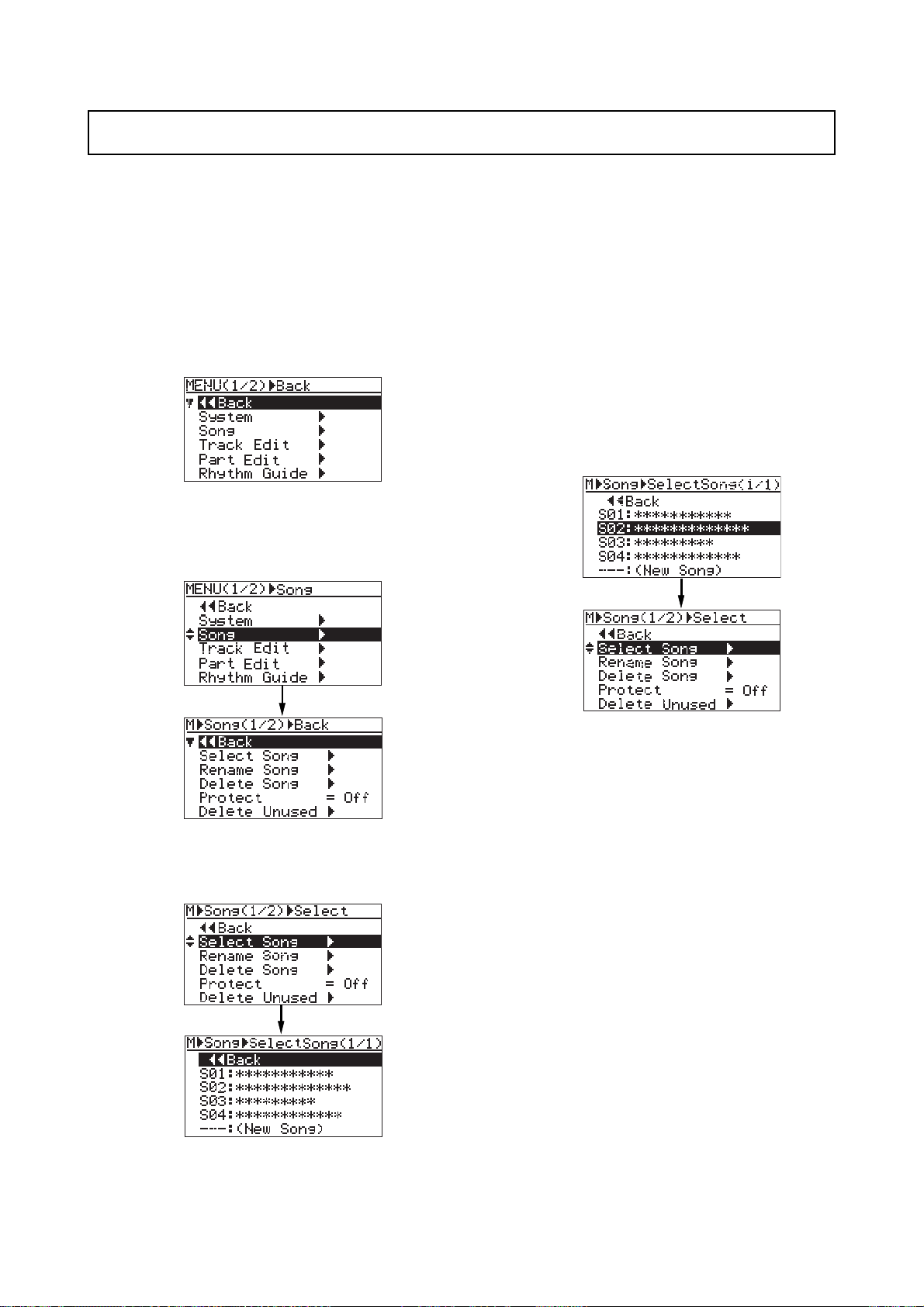
MR-8mkII Owner’s Manual (Song management)
Selecting the desired song
The following describes how to select the desired song from the CompactFlashTM Card when
more than one song is created on the CompactFlashTM Card. You can also create a new song by
the similar procedure. See "Preparations" (page 23) for details about how to create a new song.
1) While the recorder is stopped, press the
[MENU/ENTER] key to enter the menu mode.
The display now shows the first page of the
menu selection screen, where "<< Back" is
highlighted initially (selecting "<< Back"
returns to the previous screen).
2) Rotate the JOG dial to select "Song >", and press
the [MENU/ENTER] key.
The display now shows the song menu screen,
where "<< Back" is highlighted.
When more songs are created, the song list
screen has more than one page, and you can
scroll the list by rotating the JOG dial.
"- - - :(New Song)" at the bottom of the screen is
used when you create a new song.
4) Rotate the JOG dial to select the desired song
number/song name, and press the
[MENU/ENTER] key.
The display returns to the song menu screen,
where "Select Song >" is highlighted.
3) Rotate the JOG dial to select "Select Song >" and
press the [MENU/ENTER] key.
The display now shows the song list screen.
The screen example above shows that four
songs are currently created on the
CompactFlash
on a single page.
TM
Card. The song list is shown
5) Press the [STOP] key to exit the menu mode.
The display shows the home screen of the
selected song.
90
Page 91
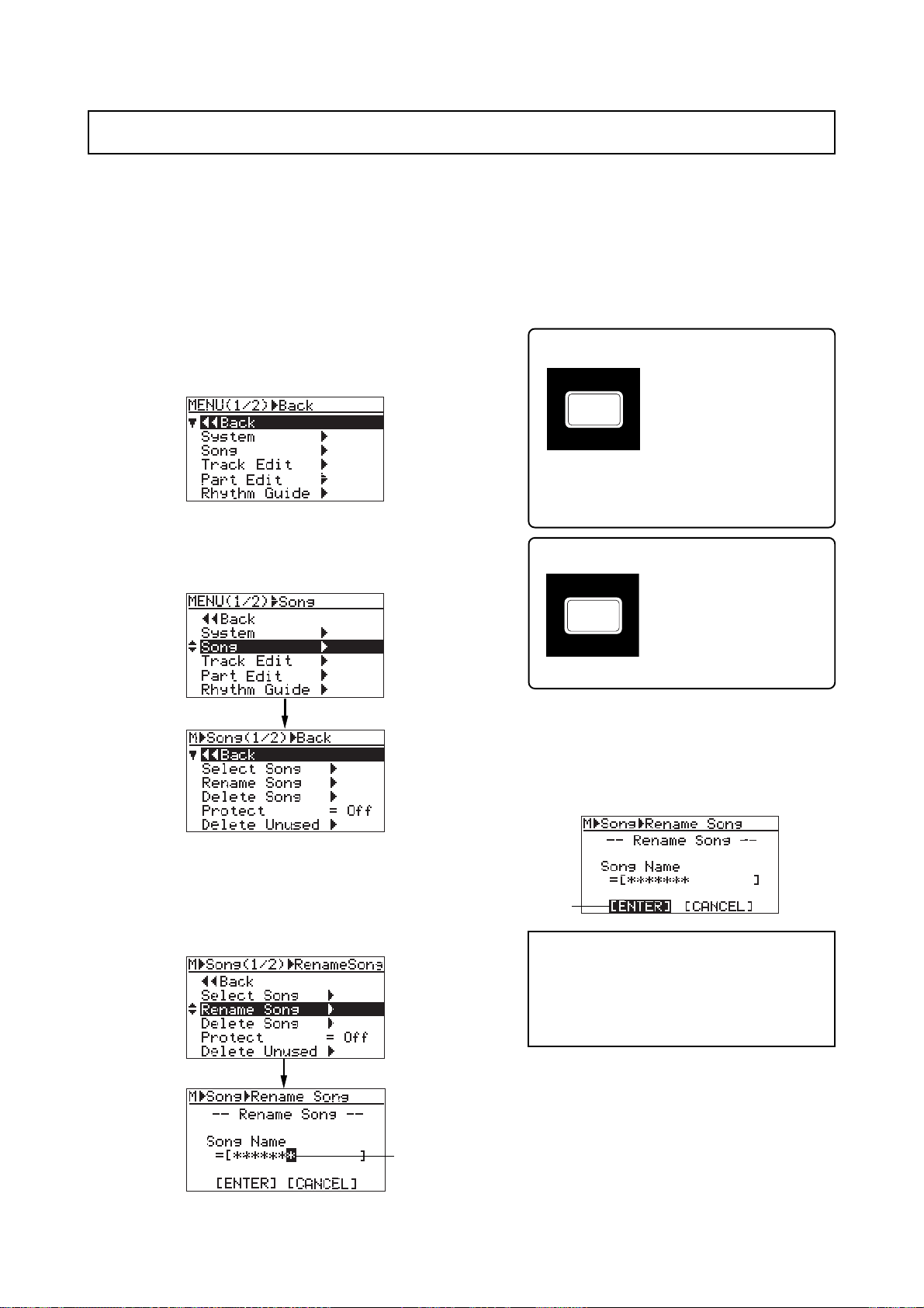
MR-8mkII Owner’s Manual (Song management)
DELETE
UNDO/REDO
Editing a song name
You can edit a current song name save the edited song name. Only the current song can be
edited.
1) Load the desired song of which you are going to
edit the song name.
2) While the recorder is stopped, press the
[MENU/ENTER] key to enter the menu mode.
The display now shows the first page of the
menu selection screen, where "<< Back" is
highlighted initially (selecting "<< Back"
returns to the previous screen).
3) Rotate the JOG dial to select "Song >", and press
the [MENU/ENTER] key.
The display now shows the song menu screen,
where "<< Back" is highlighted.
5) Use the character entry keys to enter the desired
character to the flashing point.
You can move the cursor (flashing point) by
rotating the JOG dial (or by pressing another
character entry key).
<Character entry keys>
Some keys on the MR-8mkII
PLAY MODE
top panel act as character
entry keys in the menu mode.
For example, the [PLAY
STU7
MODE] key (shown on the
left) can be used to enter S,
T, U, s, t, u and 7. Each press of a character
entry key switches the character to be entered
from among those assigned to the key.
<[DELETE] key>
Pressing the [DELETE] key
deletes the character at the
flashing point. By pressing this
key repeatedly, you can de-
lete all characters under the
flashing point.
4) Rotate the JOG dial to select "Rename Song >",
then press the [MENU/ENTER] key.
The display now shows the screen for song
name editing of the current song, on which the
rightmost character of song name flashes.
flashing
6) After entering the name, press the [MENU/ENTER]
key .
The cursor moves to "[ENTER]" at the bottom
of the screen. To cancel the operation, use the
JOG dial to highlight “[CANCEL]” and press the
[MENU/ENTER] key.
flashing
<Note>:
existing song or do not enter a name in step
5 and press the [MENU/ENTER] key in step
6 below, the display shows "Illegal Song
Name!" and returns to the song name editing screen.
If you enter the same name as an
7) Press the [MENU/ENTER] key again.
The edited name is stored and the display
returns to the song menu screen, where
“Rename Song >” is highlighted.
8) Press the [STOP] key to exit the menu mode.
The MR-8mkII exits the menu mode and the
display shows the home screen where the
edited song name is displayed.
91
Page 92
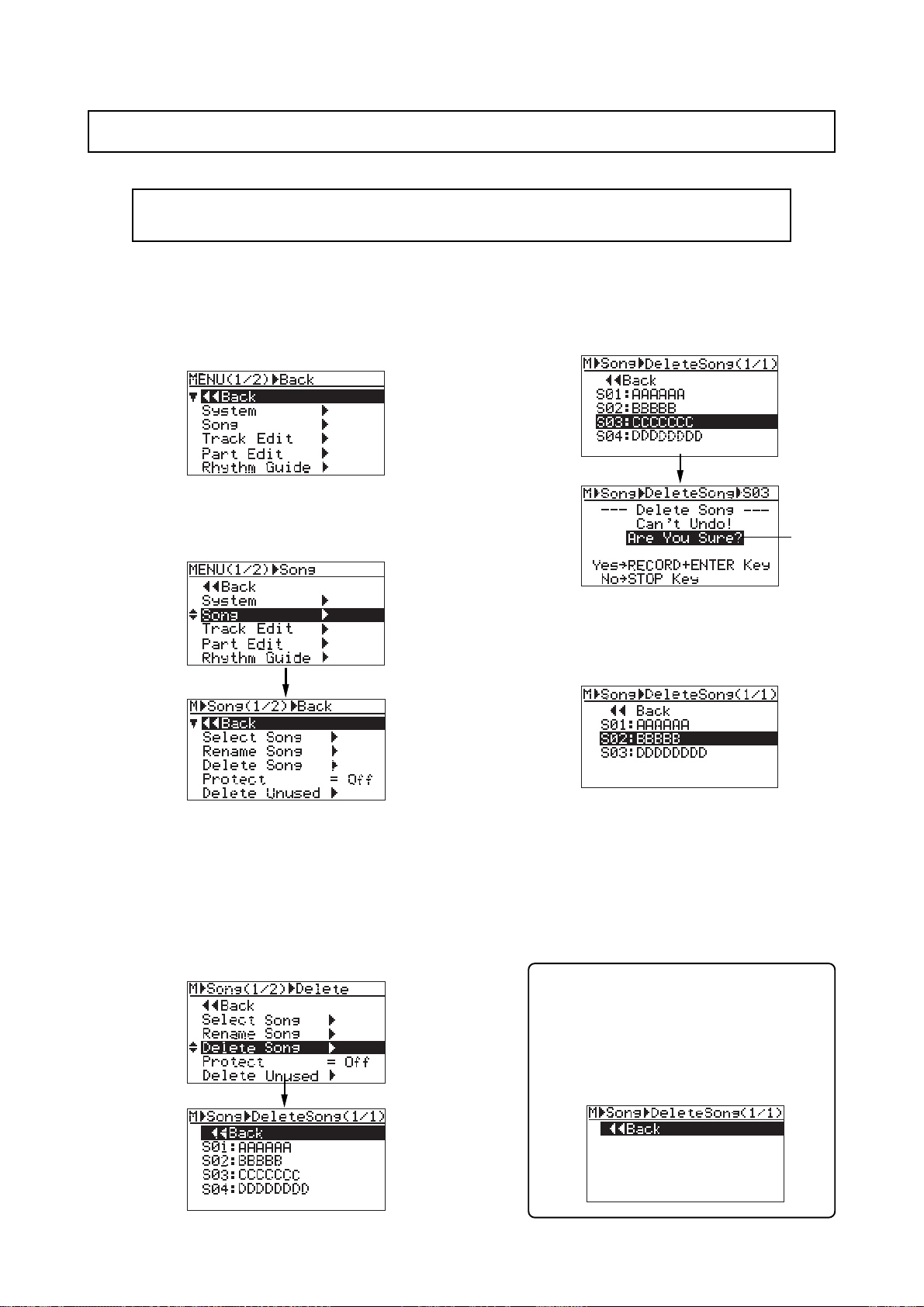
MR-8mkII Owner’s Manual (Song management)
Deleting an unnecessary song
You can delete a song created on the CompactFlashTM Card.
<Note>:
tion of the song first (see the next page).
You cannot delete a song which is protected. To delete such a song, release the protec-
1) While the recorder is stopped, press the
[MENU/ENTER] key to enter the menu mode.
The display now shows the first page of the
menu selection screen, where "<< Back" is
highlighted initially.
2) Rotate the JOG dial to select "Song >", and press
the [MENU/ENTER] key.
The display now shows the song menu screen,
where "<< Back" is highlighted.
4) Rotate the JOG dial to select a song to be
deleted, and press the [MENU/ENTER] key.
The display shows warning and confirmation
for deleting the song.
flashing
5) Press the [MENU/ENTER] key while holding
down the [RECORD] key.
The selected song is deleted, and the display
returns to the song list screen.
3) Rotate the JOG dial to select "Delete Song >", and
press the [MENU/ENTER] key .
The display now shows the list of songs
created on the CompactFlash
which you select a song to be deleted. In the
screen example below, five songs are created
so the list has only one page. (If more than five
songs are created, the list has more than one
page.)
TM
Card, from
Any song number greater than the song number of the deleted song is moved up.
In the screen example above, after Song 03 is
deleted, ex-Song 04 is moved up to Song 03
and ex-Song 05 is moved up to Song 04.
6) Press the [STOP] key to exit the menu mode.
In the example above, the display now shows
the home screen of new Song 03 (ex-Song 04).
If you delete all songs on the card by repeating the procedure above, only highlighted “<<Back” is shown on the song list.
If you exit the MENU mode by pressing the
[STOP] key, a new song (Song01) is automatically created and the display shows the
Home screen of Song01.
92
Page 93
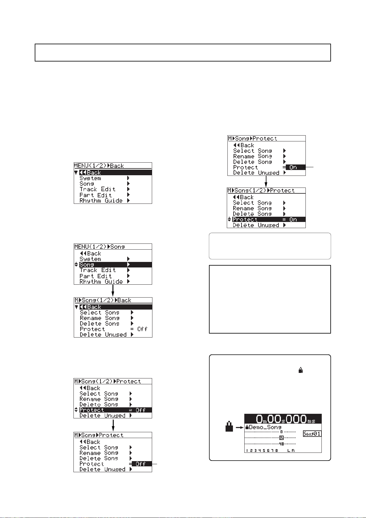
MR-8mkII Owner’s Manual (Song management)
Protecting a song
You can protect a song to prevent an accidental erasure. The protection can be released whenever you want. To keep a recorded song safely, we recommend protecting it. You can make
protection setting only for the current song.
1) Load the song you want to protect.
2) While the recorder is stopped, press the
[MENU/ENTER] key to enter the menu mode.
The display now shows the first page of the
menu selection screen, where "<< Back" is
highlighted initially (selecting "<< Back"
returns to the previous screen).
3) Rotate the JOG dial to select "Song >", and press
the [MENU/ENTER] key.
The display now shows the song menu screen,
where "<< Back" is highlighted.
5) Rotate the JOG dial to select "On", and press the
[MENU/ENTER] key.
The current song is now protected.
The display returns to the previous screen.
flashing
T o release the protection, carry out the same procedure above but select "Off" and press the
[MENU/ENTER] key in step 5.
<Note>:
editing to a protected song. If you want to
make recording or editing to a protected
song, you must release the protection first.
You cannot make recording or
4) Rotate the JOG dial to select "Protect = Off", then
press the [MENU/ENTER] key.
The current option flashes.
The default option is "Off".
flashing
<Note>:
"On", all the recording-related keys, such
as the [REC SELECT] and [BOUNCE] keys,
are turned off.
6) Press the [STOP] key to exit the menu mode.
When you set the protection to
<Tips>
When the protected song is loaded, “ ” is shown
in the upper left corner of the Home screen (indicated by the arrow in the screen example below).
When this icon is shown, you cannot make recording or edit the song.
93
Page 94
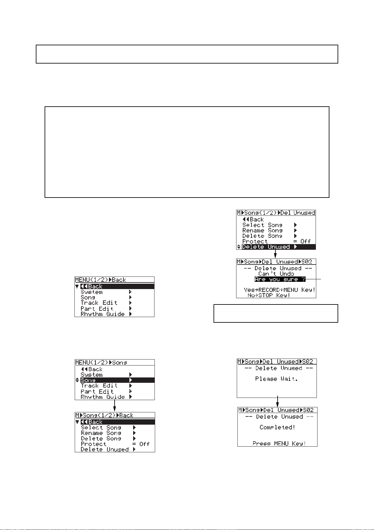
MR-8mkII Owner’s Manual (Song management)
Deleting an unused WA V file in a song
Each time you make recording or editing, a WAV file for undo operation is created in the song.
Such files are used only in undo operation. Therefore, if you complete the song and you do not
make undo/redo operation any more, these files are never used. You can delete such unused
files using the "Delete Unused" menu item for increasing the free card space.
<Note>
• You cannot delete the unused WAV files of a song which is protected. To delete unused files,
release the protection of the song in advance (see page 93).
• You cannot undo deleting unused WAV files, so make sure that you never used the files when
executing the "Delete Unused" menu item.
• After deleting the unused files, no undo/redo operation is possible with the song. However,
each time you make recording after then, a new WAV file for undo operation is created.
• With the default setting, the MR-8mkII automatically deletes the unused WAV files when
deleting track data (or part data) within a song (without the need of executing "Delete
Unused").
1) Load the song of which you want to delete the
unused files.
2) While the recorder is stopped, press the
[MENU/ENTER] key to enter the menu mode.
The display now shows the first page of the
menu selection screen, where "<< Back" is
highlighted initially (selecting "<< Back"
returns to the previous screen).
3) Rotate the JOG dial to select "Song >", and press
the [MENU/ENTER] key.
The display now shows the song menu screen,
where "<< Back" is highlighted.
flashing
<Note>:
files, press the [STOP] key.
5) Press the [MENU/ENTER] key while holding
down the [RECORD] key.
The unused files are deleted. When completed,
"Completed!" is shown.
To cancel deleting the unused
4) Rotate the JOG dial to select "Delete Unused >",
then press the [MENU/ENTER] key.
The display shows the confirmation screen for
deleting unused WAV files.
6) Press the [MENU/ENTER] key.
The display changes to show the screen where
"Delete Unused>" is highlighted.
7) Press the [STOP] key to exit the menu mode.
94
Page 95
MR-8mkII Owner’s Manual (Track data editing)
Track data editing
This chapter describes the track data editing function for a recorded
song. "Track data" means all data from the beginning (ABS0) to the
end (REC END) of a song.
<Undo/redo of track editing>
By pressing the [UNDO/REDO] key after executing track editing, you can
undo the editing. By pressing the [UNDO/REDO] key after the undo operation, you can return the track(s) to the condition after being edited.
<Notes>:
UNDO/REDO
DELETE
<Note>:
data (while you can undo or redo all other track editing). Because erasing track data completely deletes track data from a card, the free card
space increases after erasing track data. If you want to make it possible
undo or redo erasing track data, set the "Auto Delete" menu item of the
"System" menu in the MENU mode to "Off" (see page 135). In this case,
however, note that the free card space does not increase after erasing
track data.
<Notes>:
or directly exit the menu mode by the following operations.
(1) Select “<< Back” on a menu screen and press the [MENU/ENTER] knob.
With the default setting, you cannot undo or redo erasing track
While a menu screen is shown, you can go up the menu screen level
The display returns to the previous (upper level) screen. Repeating
this operation finally exits the menu mode.
ing after editing, you cannot undo the editing anymore.
Also note that, if you carry out any of the follow-
1. Making new recor ding
2. Making new editing
3. Turning off the power
4. Loading another song
(2) Press the [REWIND] key .
The display returns to the previous (upper level) screen.
Repeating this operation finally exits the menu mode.
(3) Press the [STOP] key.
The menu mode exits and the display shows the home screen.
95
Page 96
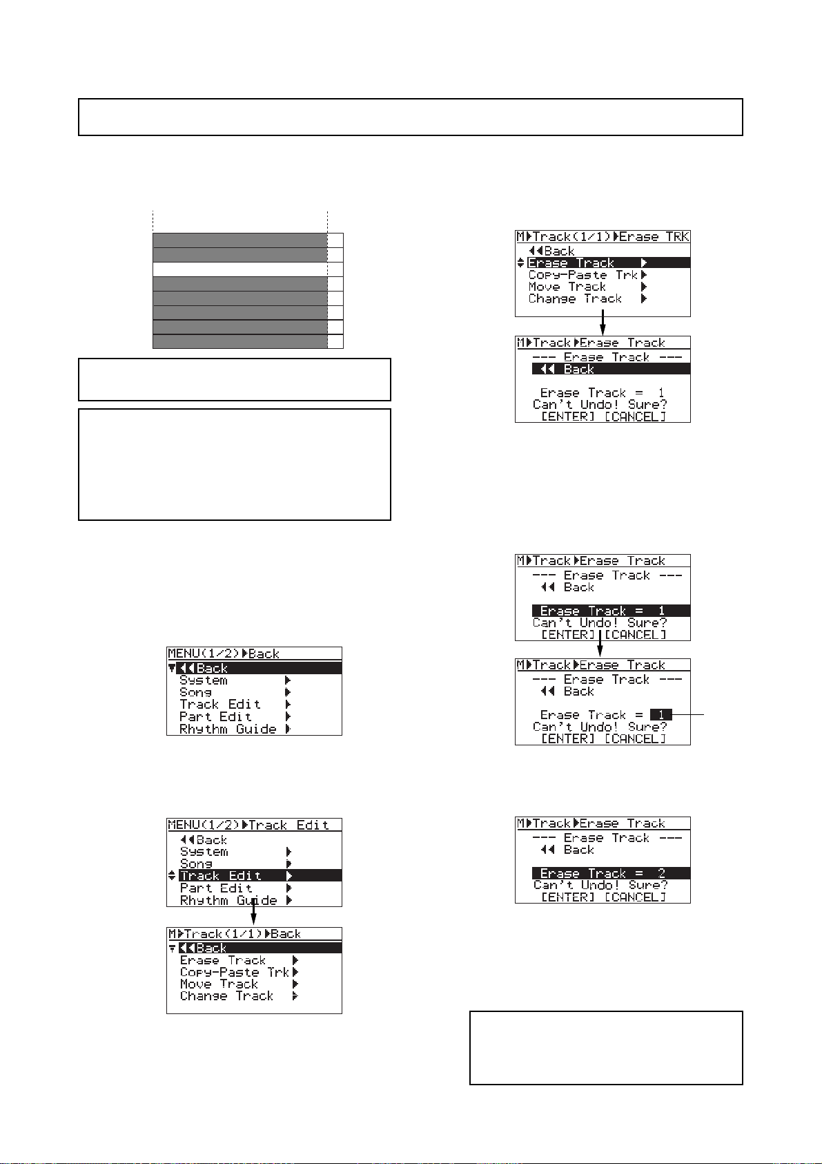
MR-8mkII Owner’s Manual (Track data editing)
Erasing track data
You can erase whole data (from ABS ZERO to REC END) of the desired track(s) of the song currently loaded.
As you can see from the message on the screen
ABS ZERO
TRK 1
TRK 2
TRK 3
TRK 4
TRK 5
TRK 6
TRK 7
TRK 8
REC END
Silent
("Can't Undo! Sure?"), you cannot undo erasing track data.
<Note>:
tected.
<Note>:
You cannot erase track data of a song pro-
With the default setting, you cannot
undo or redo erasing track data. If you want to
make it possible to undo or redo erasing track
data, set the "Auto Delete" menu item of the
"System" menu in the MENU mode to "Off" (see
page 135).
1) Load the song you want to edit.
2) While the recorder is stopped, press the
[MENU/ENTER] key to enter the menu mode.
The display now shows the first page of the
menu selection screen, where "<< Back" is
highlighted initially .
3) Rotate the JOG dial to select "T rac k Edit >", and
press the [MENU/ENTER] key.
The display now shows the track edit menu
screen, where "<< Back" is highlighted.
5) Rotate the JOG dial to select "Erase Track = 1",
and press the [MENU/ENTER] key.
The currently selected option flashes and you
can now select the desired option by rotating
the JOG dial. The available options are:
• 1 through 8 (mono track)
• 1/2, 3/4, 5/6 and 7/8 (stereo tracks)
flashing
6) Rotate the JOG dial to select the desired option,
and press the [MENU/ENTER] key.
“Erase Track = *” is now highlighted on the
screen.
4) Rotate the JOG dial to select "Erase T rac k >", and
press the [MENU/ENTER] key.
The display now shows the screen for
selecting the track(s) to be erased.
7) Rotate the JOG dial to move the cursor to
"[ENTER]" on the screen, and press the
[MENU/ENTER] key.
The display shows "Please Wait", immediately
followed by "Completed" when the MR-8mkII
completes erasing.
<Note>:
eration, move the cursor to "[CANCEL]" on
the screen, and press the [MENU/ENTER]
knob.
If you want to cancel the erase op-
96
Page 97
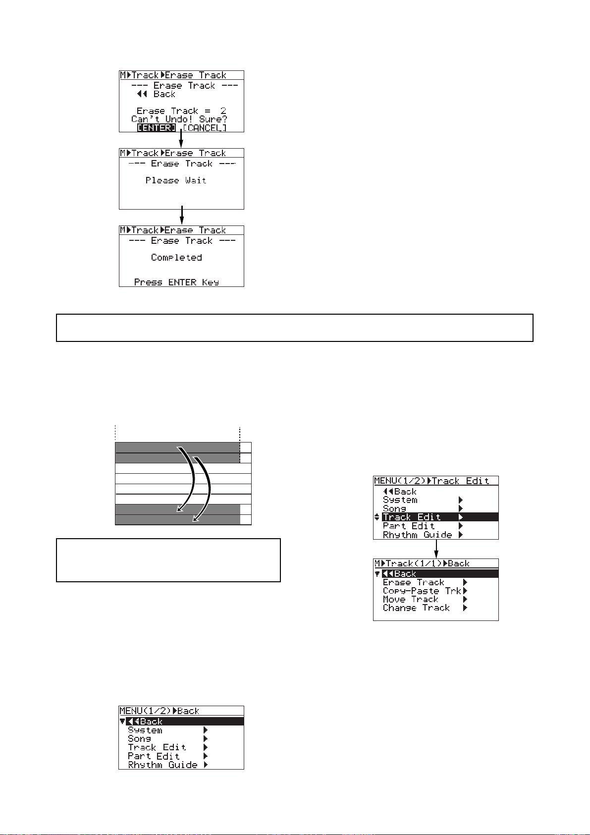
MR-8mkII Owner’s Manual (Track data editing)
8) Press the [MENU/ENTER] key.
The display now returns to the track edit menu
screen, where “Erase Track >” is highlighted.
9) Press the [STOP] key to exit the menu mode.
Copying/pasting trac k data
You can copy whole data (from ABS ZERO to REC END) of the desired track(s) of the song currently loaded and paste it to the other desired track(s). The data on the source track(s) still
remains after the copy/paste operation. Copy/paste operation can be done within the currently
loaded song.
ABS ZERO
TRK 1
TRK 2
TRK 3
TRK 4
TRK 5
TRK 6
TRK 7
TRK 8
<Note>:
protected. Release the protection before copying/
pasting track data.
1) Load the song you want to edit.
You cannot copy/paste track data of a song
REC END
3) Rotate the [MENU/ENTER] knob to select
"T rac k Edit >", and press the [MENU/ENTER]
knob.
The display now shows the track edit menu
screen, where "<< Back" is highlighted.
2) While the recorder is stopped, press the
[MENU/ENTER] key to enter the menu mode.
The display now shows the first page of the
menu selection screen, where "<< Back" is
highlighted initially (selecting "<< Back"
returns to the previous screen).
4) Rotate the JOG dial to select "Copy-Paste Trk >",
and press the [MENU/ENTER] key.
The display now shows the screen for
selecting the source track(s) and destination
track(s) of copy/paste operation.
"Source Track" selects the copy source track(s),
while "Dest. Track" selects the paste
destination track(s).
97
Page 98
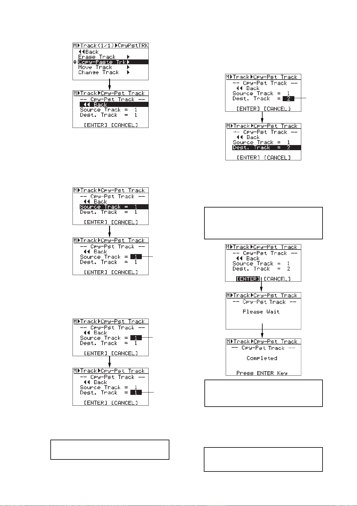
MR-8mkII Owner’s Manual (Track data editing)
5) Rotate the JOG dial to select "Source T rack = 10º",
and press the [MENU/ENTER] key.
You can now select the desired copy source
track(s) by rotating the JOG dial.
The available options are:
• 1 through 8 (mono track)
• 1/2, 3/4, 5/6 and 7/8 (stereo tracks)
7) Rotate the JOG dial to select the destination track(s),
and press the [MENU/ENTER] key .
“Dest. Track = *” is now highlighted on the
screen.
flashing
8) Rotate the JOG dial to move the cursor to
"ENTER" at the bottom of the screen, then press
the [MENU/ENTER] key .
The display shows "Please Wait", immediately
followed by "Completed" when the MR-8mkII
completes the copy/paste operation.
flashing
6) Rotate the JOG dial to select the source track(s)
to be copied, and press the [MENU/ENTER] key.
You can now select the desired copy
destination track(s)
flashing
flashing
<Note>:
operation, move the cursor to "[CANCEL]"
on the screen, and press the [MENU/ENTER]
key.
<Note>:
data, pasting the copied data overwrites the
previous data.
If you want to cancel the copy/paste
If a destination track has recorded
You can select the same number of tracks as
the copy source track(s). For example, if you
select a mono track for the source, you can
only select a mono track for the destination.
<Note>:
for the copy source and destination.
You cannot select the same track(s)
9) Press the [MENU/ENTER] key.
The display now returns to the track edit menu
screen, where “Copy-Paste Trk >” is highlighted.
10) Press the [STOP] key to exit the menu mode.
<Note>:
sult, press the [UNDO/REDO] key to undo
the operation (see page 95).
If you are not satisfied with the re-
98
Page 99
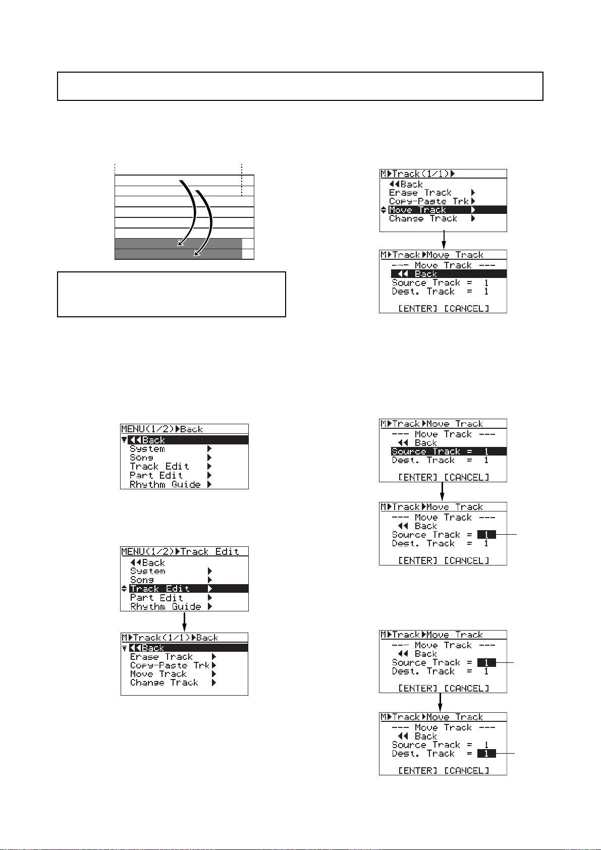
MR-8mkII Owner’s Manual (Track data editing)
Moving trac k data
You can move whole data (from ABS ZERO to REC END) of the desired track(s) to the other
desired track(s). After the data is moved, the original track(s) is(are) silent. You can only move
track data within the current song.
ABS ZERO
TRK 1
TRK 2
TRK 3
TRK 4
TRK 5
TRK 6
TRK 7
TRK 8
<Note>:
tected. Release the protection before moving track
data.
1) Load the song you want to edit.
2) While the recorder is stopped, press the
You cannot move track data of a song pro-
[MENU/ENTER] key to enter the menu mode.
The display now shows the first page of the
menu selection screen, where "<< Back" is
highlighted initially (selecting "<< Back"
returns to the previous screen).
REC END
5) Rotate the JOG dial to select "Source Track = *",
and press the [MENU/ENTER] key.
You can now select the desired move source
track(s) by rotating the JOG dial.
The available options are:
• 1 through 8 (mono track)
• 1/2, 3/4, 5/6 and 7/8 (stereo trac ks)
3) Rotate the JOG dial to select T rack Edit >", and press
the [MENU/ENTER] key .
The display now shows the track edit menu
screen, where "<< Back" is highlighted.
4) Rotate the JOG dial to select "Move Track >", and
press the [MENU/ENTER] key.
The display now shows the screen for
selecting the source track(s) and destination
track(s) of the move operation. "Source Track"
selects the move source track(s), while "Dest.
Track" selects the move destination track(s).
flashing
6) Rotate the JOG dial to select source track(s), and
press the [MENU/ENTER] key.
You can now select the desired destination
track(s).
flashing
flashing
99
Page 100
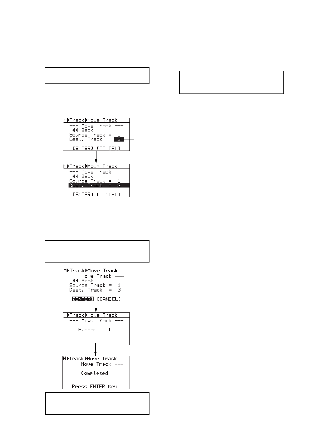
MR-8mkII Owner’s Manual (Track data editing)
You can select the same number of tracks as
the move source track(s). For example, if you
select a mono track for the move source, you
can only select a mono for the move destination.
<Note>:
for the move source and destination.
You cannot select the same track(s)
7) Rotate the JOG dial to select destination track(s),
and press the [MENU/ENTER] key.
“Dest. Track = *” is now highlighted on the
screen.
flashing
9) Press the [MENU/ENTER] key .
The display now returns to the track edit menu
screen, where “Move Track >” is highlighted.
10) Press the [STOP] key to exit the menu mode.
<Note>:
sult, press the [UNDO/REDO] key to undo
the operation (see page 95).
If you are not satisfied with the re-
8) Rotate the JOG dial to move the cursor to
"[ENTER]" on the screen, and press the
[MENU/ENTER] key.
The display shows "Please Wait", immediately
followed by "Completed" when the MR-8mkII
completes the move operation.
<Note>:
tion, move the cursor to "[CANCEL]" on the
screen, and press the [MENU/ENTER] key.
If you want to cancel the move opera-
<Note>:
data, moving data overwrites the previous
data.
If a destination track has recorded
100
 Loading...