


MR-8
Owner’s Manual
Digital Multitracker
8588 018 100 (376785)
2
MR-8 Owner’s Manual
CAUTION: TO REDUCE THE RISK OF ELECTRIC SHOCK,
DO NOT REMOVE COVER (OR BACK).
NO USER - SERVICEABLE PARTS INSIDE.
REFER SERVICING TO QUALIFIED SERVICE PERSONNEL.
RISK OF ELECTRIC SHOCK
DO NOT OPEN
10. Power Sources - The appliance should be connected to a
power supply only of the type described in the operating
instructions or as marked on the appliance.
11. Grounding or Polarization - The precautions that should be
taken so that the grounding or polarization means of an
appliance is not defeated.
12. Power Cord Protection - Power supply cords should be routed
so that they are not likely to be walked on or pinched by items
placed upon or against them, paying particular attention to
cords at plugs, convenience receptacles, and the point where
they exit from the appliance.
13. Cleaning - The appliance should be cleaned only as
recommended by the manufacturer.
14. Nonuse Periods - The power cord of the appliance should be
unplugged from the outlet when left unused for a long period
of time.
15. Object and Liquid Entry - Care should be taken so that objects
do not fall and liquids are not spilled into the enclosure through
openings.
16. Damage Requiring Service - The appliance should be
serviced by qualified service personnel when:
A. The power supply cord or the plug has been damaged;
or
B. Objects have fallen, or liquid has been spilled into the
appliance; or
C. The appliance has been exposed to rain; or
D. The appliance does not appear to operate normally or
exhibits a marked change in performance; or
E. The appliance has been dropped, or the enclosure
damaged.
17. Servicing - The user should not attempt to service the
appliance beyond that described in the operating instructions.
All other servicing should be referred to qualified service
personnel.
18. The appliance should be situated away from drops of water
or spray of water.
19. Objects containing liquid such as vase must not be put on
the appliance.
20. The appliance is not completely isolated from the power supply
even if the power switch is at off position.
The exclamation point within an equilateral triangle is intended
to alert the user to the presence of important operating and
maintenance (servicing) instructions in the literature
accompanying the appliance.
CAUTION:
TO PREVENT ELECTRIC SHOCK, MATCH WIDE BLADE OF PLUG
TO WIDE SLOT, FULLY INSERT.
ATTENTION:
POUR EVITER LES CHOCS ELECTRIQUES, INTRODUIRE LA LAME
LA PLUS LARGE DE LA FICHE DANS LA BORNE CORRESPONDANTE
DE LA PRISE ET POUSSER JUSQU' AU FOND.
An appliance and cart combination should be moved with
care. Quick stops, excessive force, and uneven surfaces may
cause the appliance and cart combination to overturn.
7. Wall or Ceiling Mounting - The appliance should be mounted
to a wall or ceiling only as recommended by the manufacturer.
8. Ventilation - The appliance should be situated so that its
location or position dose not interfere with its proper ventilation.
For example, the appliance should not be situated on a bed,
sofa, rug, or similar surface that may block the ventilation
openings; or, placed in a built-in installation, such as a
bookcase or cabinet that may impede the flow of air through
the ventilation openings.
9. Heat - The appliance should be situated away from heat
sources such as radiators, heat registers, stoves, or other
appliances (including amplifiers) that produce heat.
"WARNING"
"TO REDUCE THE RISK OF FIRE OR ELECTRIC SHOCK, DO
NOT EXPOSE THIS APPLIANCE TO RAIN OR MOISTURE."
SAFETY INSTRUCTIONS
1. Read Instructions - All the safety and operating instructions
should be read before the appliance is operated.
2. Retain Instructions - The safety and operating instructions
should be retained for future reference.
3. Heed Warnings - All warnings on the appliance and in the
operating instructions should be adhered to.
4. Follow Instructions - All operating and use instructions should
be followed.
5. Water and Moisture - The appliance should not be used near
water - for example, near a bathtub, washbowl, kitchen sink,
laundry tub, in a wet basement, or near a swimming pool,
and the like.
6. Carts and Stands - The appliance should be used only with a
cart or stand that is recommended by the manufacturer.
CAUTION
The lightning flash with arrowhead symbol, within an equilateral
triangle, is intended to alert the user to the presence of
uninsulated “dangerous voltage” within the product’s enclosure
that may be of sufficient magnitude to constitute a risk of electric
shock to persons.

3
MR-8 Owner’s Manual
Table of Contents
Introduction ...........................................................5
MR-8 Main features ...............................................5
About power supply .............................................5
Precaution upon handling the MR-8 ................6
Notes on repair ......................................................6
About copyrights ..................................................6
About damages ......................................................6
The basics of the MR-8........................................7
Recording method ................................................7
Song mode ..............................................................7
About song ..............................................................7
Time base ................................................................8
Remain display ......................................................9
Input monitor and repro monitor .....................9
TRIM control ..........................................................9
Names and Functions ......................................10
Top panel (left part) ...........................................10
Top panel (right part) ........................................12
Rear panel .............................................................14
Side panel .............................................................15
Bottom panel .......................................................15
About recording medium.................................16
CompactFlash
TM
card .........................................16
Recording time ....................................................16
Inserting a CompactFlash
TM
card ....................16
How to remove a CompactFlash
TM
card ...16
How to insert a CompactFlash
TM
card ......16
About the power .................................................17
Connecting the AC adaptor ..............................17
Inserting batteries ...............................................17
Turning on the unit ............................................17
Turning off the power ........................................18
Turning on the LCD display backlight ...........18
Low battery display ............................................18
Listening the demo song .................................19
Preparation of a CompactFlash card ............20
Preparation for recording
onto the supplied card ................................20
Preparation for recording
onto a new card .............................................22
Creating a song/selecting a song ..................23
Creating a song ....................................................23
Selecting a desired song ....................................24
Formatting a card ...............................................25
Connections .......................................................26
Display ..................................................................27
Home screen ........................................................27
Selecting a time base ..........................................28
Adjusting the display contrast .........................28
MENU screen ........................................................28
Warning message ................................................28
MR-8 recording basics .....................................29
Relation between
the input jacks and tracks ...........................29
[INPUT A SELECT] switch ...................................29
Input level setting ...............................................30
Distortion setting ................................................30
Insert effects .........................................................30
Recording onto a single track .........................31
Preparation for recording .................................31
Starting recording ..............................................32
Playback the recorded track .............................32
Undo/redo ...........................................................32
Recording onto two trac ks ..............................33
Preparation for recording .................................33
Starting recording ..............................................34
Playback the recorded tracks ...........................34
Undo/redo ...........................................................34
Punch in/out ........................................................35
Punch in/out using the keys
on the top panel ............................................35
Punch in/out using the footswitch .................35
Auto punch in/out .............................................36
Setting the punch-in
and punch-out points ...........................36
Rehearsal ........................................................36
Actual auto punch in/out ...........................37
Using effects .......................................................38
Using the insert effects for recording .............38
Mic simulation effects ..................................38
Amp simulation effects ...............................38
Using the reverb or delay ..................................39
Selecting an effect type ................................39
Selecting a delay type ..................................39
Adjusting the delay/reverb time ..............40
Adjusting the effect send levels .................40
Using the mastering effects ..............................41
Selecting the desired effect type ................41
Bouncing tracks .................................................42
Selecting the bounce mode ...............................43
Rehearsal of track bounce .................................44
Actual track bounce ...........................................45
Checking the bounced signals on track .........45

4
MR-8 Owner’s Manual
Mixdown ..............................................................47
Analog mixdown .................................................47
Digital mixdown ..................................................48
Playback functions ............................................49
Basic playback .....................................................49
3 x playback (cueing) .........................................49
Playback between LOCATE A and B points ...49
Play mode .............................................................50
Selecting a play mode ..................................50
Auto play mode ............................................50
Auto return mode ........................................50
Loop mode .....................................................50
Loop function in auto punch in/out mode ...51
Locate functions ................................................52
ABS locate .............................................................52
LOCATE ABS ZERO function .......................52
LOCATE REC END function .........................52
Zero return ...........................................................52
Resetting the counter ...................................52
Locating to counter zero .............................53
Locating to the LOCATE A or B point ..............53
Storing a locate point ...................................53
Locating ..........................................................54
Setting the pre-roll/post-roll .............................55
How to set the pre-roll/post-roll time .............55
Setting the beat resolution ...............................56
How to set the beat resolution ..........................56
Editing a song .....................................................57
Creating a new song ...........................................57
Selecting a desired song ....................................57
Editing a song name ...........................................58
Selecting an unnecessary song ........................59
Protecting a song .................................................60
Deleting the unnecessary file in a song ..........61
T rack editing ........................................................62
Erasing whole track data ...................................62
Copying/pasting whole track data .................63
Moving whole track data ...................................65
Exchange whole track data ...............................66
Part editing ..........................................................68
Erasing a desired part ........................................69
Copying/pasting (1) ..........................................70
Copying to the clipboard ............................70
Pasting clipboard data .................................71
Copying/pasting (2) ........................................72
Moving the desired part
to the other track (s) ....................................73
Exchange parts between tracks .......................75
Synchronizing with MIDI ..................................77
Synchronization using MTC .............................77
Settings of the MR-8
and MIDI sequencer ........................77
MIDI sync/MTC frame rate settings .........77
Synchronization using MIDI clock ..................78
Using the rhythm guide function ....................79
Creating the signature/tempo map ................79
Setting the signature map ...........................79
Changing the bar number
or signature .......................................80
Deleting an unnecessary
bar/signature setting ......................81
Changing the bar offset ...............................81
Creating the tempo map .............................82
Editing the tempo map ................................84
Deleting an unnecessary tempo setting ..84
Setting the click level ..........................................85
W AV file con version ..........................................86
Enabling the file conversion .............................86
Procedure of file conversion ............................86
Exporting data to a personal computer ........88
Connection to a personal Computer ..............88
Notes on exporting a file ....................................88
Exporting a WAV file to
a personal computer .............................89
Initializing the MR-8 ...........................................91
T roubleshooting .................................................92
MR-8 specifications ...........................................95
Physical dimensions ........................................96
Block diagram ....................................................96
MIDI Implementation Chart .............................98
Index .....................................................................99
Optional accessaries ......................................100
Declaration of EC Directive ...........................101

5
MR-8 Owner’s Manual
MR-8 Main features
About power supply
Thank you very much for purchasing the Fostex MR-8 digital multitracker. The MR-8 is
a digital multitracker which records and plays back 8-track audio on a CompactFlash
TM
card. You can record audio at 44.1 kHz/16 bits (in the normal mode) or 22.05 kHz/16
bits (in the extended mode). The MR-8 is also equipped with an 8-channel digital mixer,
digital effects including the delay/reverb, mastering effects and insert effects (simula-
tion effects). It allows you to carry out all the process for digital multitrack recording
including overdubbing, track bounce and mixdown.
Read this manual thoroughly for using all functions the MR-8 provides correctly.
• Uses compact and reliable CompactFlash
TM
cards for recording high quality audio. You
can also edit recorded audio later.
• User-friendly LCD screen configuration allows
you to make recording intuitively.
• A large 128 x 64 dot graphic LCD display
allows you to check the recorder status and
various settings easily.
• An ASP digital effect processor (delay/reverb)
with newly developed algorithm for the MR-8
is built in. In addition, the MR-8 also provides
insert effects for microphone and amplifier
simulation for coloring sounds.
• A dedicated mastering effect is built in for the
stereo buss, allowing you to process a sound
during track bouncing or final mixdown.
• The metronome function generates guide clicks
according to the tempo map.
• Built-in compact and high quality microphone
allows you to record microphone sound
without an external microphone.
• Two ways of receiving power. You can drive
the MR-8 by batteries (AA-type) or from the
supplied AC adaptor (AD-12A).
• Provides a USB terminal. You can exchange
WAV file data between your computer and the
MR-8 via USB connection. You can not only back
up song data recorded by the MR-8 to your
computer, but also import data created by a
computer music software to the MR-8, or burn
CDs by the computer using the CD-RW drive.
• Be sure to connect the MR-8 to the power
supply specified in the Specifications section
of this owner’s manual. Do not use an AC
outlet of any other voltage.
• Do not connect the MR-8 to the same AC outlet
to which devices that could generate noise
(such as a large motor or dimmer), or the
devices that consume a large amount of power
(such as an air conditioning system or large
electric heater) are connected.
• If you use the MR-8 in an area with a different
power voltage, first consult your dealer or the
nearest Fostex service station.
• It is very dangerous to use a power cord that is
frayed or damage. In such a case, stop using
the MR-8 immediately and ask your dealer to
repair the cord.
• To avoid possible electric shock and damage
to the MR-8, avoid contact with water or other
liquids, or do not handle the power plug while
your hands are wet.
• To prevent possible electric shock and
damage to the MR-8, do not remove the main
unit cover or reach the inside the MR-8.
• Do not let water or other liquid, or metal
objects such as pins, accidentally enter the
inside of the MR-8 because this may lead to
electric shock or damage. Should water enter
the inside of the MR-8, remove the power plug
from AC outlet, and consult your dealer or the
nearest Fostex service station.
Introduction
6
MR-8 Owner’s Manual
Precautions upon handling the MR-8
Notes on repair
About copyrights
About damages
• Do not install the MR-8 in locations subject to
the following:
* Extremely high or low temperature, or
significant changes in temperature.
* Excessive humidity or dust.
* Excessive changes in power supply voltage.
* Unstable or significantly vibrating or
shaking surfaces.
* Near a strong magnetic field (such as a TV
or speaker).
• The MR-8 does not use any parts that user can
repair easily. Contact your dealer or the
nearest FOSTEX service station to ask about
repairs.
• Use the packing carton designed for the MR-8
when you transport the MR-8 to the dealer for
repair or return.
If you have discarded the packing box, try to
pack the MR-8 completely using shock
absorbing materials.
Fostex is not responsible for malfunction or
damage due to incomplete packaging or caused
during transport.
• It is prohibited by law to use any part of a CD
recording or video images or audio data for
which copyright is possessed by a third party
for commercial purposes such as contents,
broadcasts, sales, or distribution-any purpose
other than for your personal pleasure.
• Fostex is not responsible for any “direct
damage” or “indirect damage” caused by
using the MR-8.
MODEL MR-8
DIGITAL MULTITRACKER
FOSTEX
100V 18W
50/60Hz
SERIAL NO.
MADE IN CHINA
<Important!>
Equipment name, electrical ratings, serial
number and other information for the MR-
8, are written on bottom side.
• To prevent damage to the MR-8, be sure to
power on the connected devices first, then turn
on the power to the MR-8. When you remove
or connect the cables to the input/output
connectors on the MR-8, make sure that the
track and master faders and volume controls
are set to “0”.
Note for audio interruption
• If you make recording or editing to a song many
times, audio may be occasionally interrupted
when the song is played back, due to data
fragmentation.
Note that this is not a malfunction.
7
MR-8 Owner’s Manual
About song
Recording method
Song mode
Song01
Song02
Song03
Song04
Song05
Song99
Song98
Song01
Track 1
Track 2
Track 8
WAV file
The basics of the MR-8
The chapter describes the basics of the MR-8 you should know before using the MR-8.
The MR-8 records audio on a CompactFlash
TM
card. Songs are recorded on a card along with
the ABS time (00m00.000s through 60m00.000s).
The ABS time shows the absolute time on a card
and you can start recording from any desired
time within the range between 00m00.000s and
60m00.000s ABS time.
As the MR-8 does not consume the card space
when no audio is recorded, you can record au-
dio effectively, while the recordable time for a
tape recorder depends on the CompactFlash
TM
card capacity.
The MR-8 provides two song modes: Normal and
Extended modes. You can select an appropriate
mode when creating a new song (see page 21).
Normal mode:
Audio quality takes precedence over the recording time.
In this mode, you can record and play back 8-track
audio at 44.1 kHz, 16 bit.
The recorded audio can be output digitally from the
[DIGITAL OUT] connector, allowing digital copy to an
external digital device (such as an MD and DAT).
Extended mode:
The recording time takes precedence.
In this mode, you can record and play back 8-track
audio at 22.05 kHz, 16 bit. You can get longer record-
ing time than the normal mode (see page 16).
Note that audio recorded in the extended mode can-
not be output digitally from the [DIGITAL OUT] con-
nector.
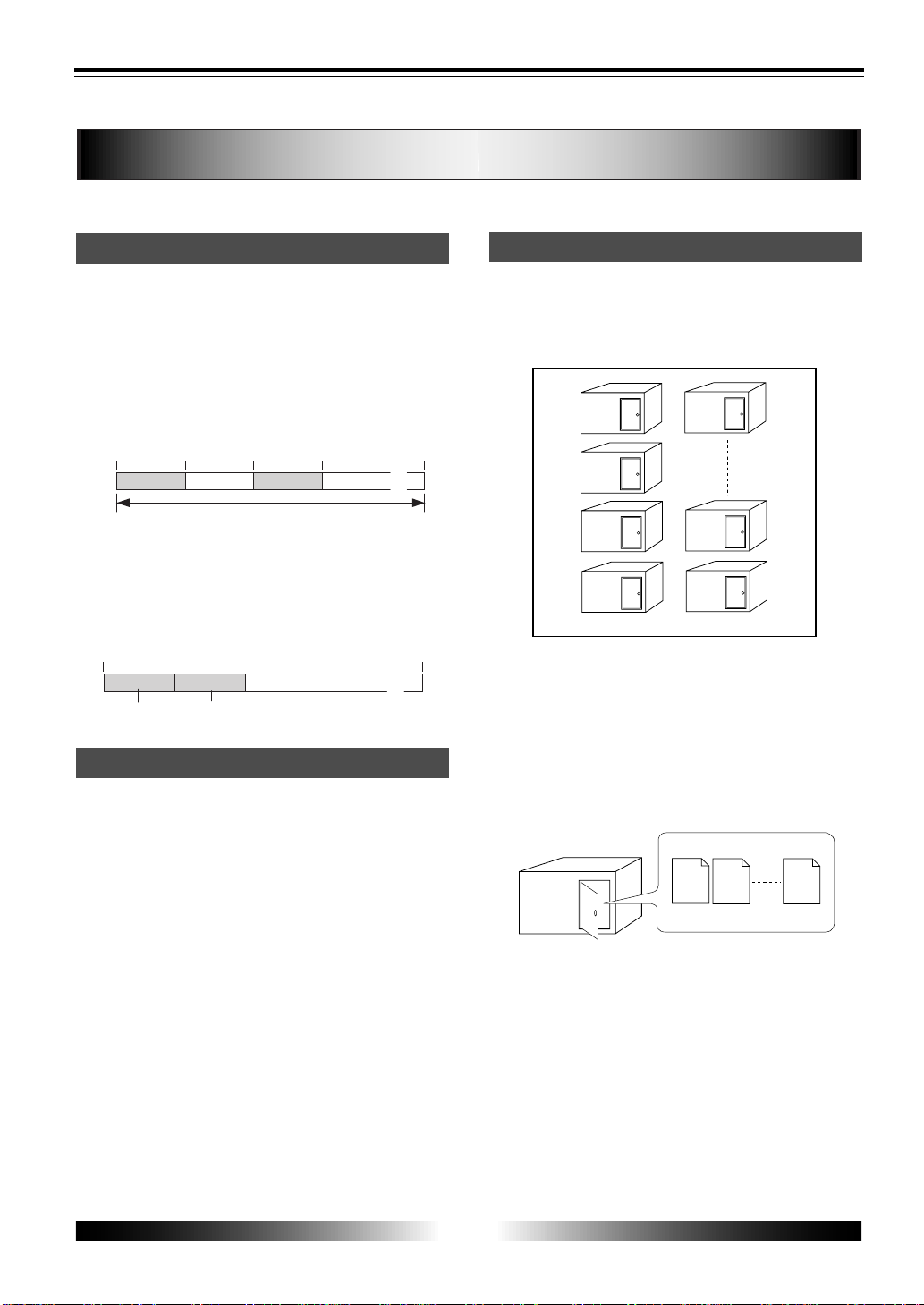
To understand songs, imagine separated rooms
as shown below. With the MR-8, you can create
up to 99 songs on a card (although the available
space may limit the number of songs).
Each song is independent on a card and you can
record, play back or edit a song without affect-
ing other songs.
You can give a desired song name for managing
recorded songs (see page 57).
Recorded track data is stored in a song as mono
WAV files, as shown below.
The MR-8 can convert the two WAV files bounced
to tracks 7 and 8 (L and R) to a stereo WAV file
(see page 86). You can export the converted ste-
reo WAV file to your USB-connected personal
computer, and use the file by a computer music
software or burn the file to a CD-R/CD-RW disc
for making an original audio CD using a CD-RW
drive connected to the computer (see page 88).
Beginning of the song
0m00.000s
(ABS ZERO)
05m00.000s 10m00.000s
15m00.000s
(REC END)
60m00.000s
recorded area recorded areaunrecorded area unrecorded area
......
You can record at any point within 60 minutes in ABS time.
5 minute recording
0m00.000s
5 minute recording
60m00.000s
recorded area recorded area
unrecorded area (remain)
......
8
MR-8 Owner’s Manual
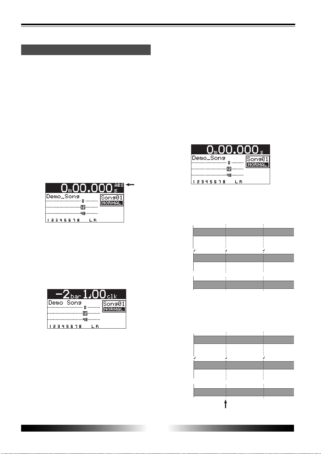
Time base
The term, "time base", is used as the reference
of recorder position information.
Using the [TIME BASE SELECT] key, you can
select from among three time base types: ABS,
Bar/Beat/Clk and Time counter.
ABS time:
ABS time stands for Absolute time, which is
"striped" on a card when creating a song. It
starts from 0m00.000s (=ABS zero, the begin-
ning of a song) and ends by 60m00.000s at
maximum.
The following screen shows that the recorder
is located at 0m00.000s of ABS time, which is
the beginning of the song.
You can see "ABS" at the right-top.
Bar/Beat/Clk:
The Bar/Beat/Clk information is created ac-
cording to the internal tempo map.
The following screen shows that the beginning
position of the song is "bar -2/beat 1/clk 000".
You can see "clk" at the right-top.
The Bar/Beat/Clk information is initially off-
set by "-2 bars" at 0m00.000s ABS time (which
is called "bar offset"). The MR-8 determines
the Bar/Beat/Clk values in a song according to
the offset, time signature and tempo.
You can change the Bar offset (initially set to
"-2") between 1 and -7 in the menu mode (see
page 81).
Time counter:
This is similar to the "time counter" mode used
for tape recorders. It shows the recorder posi-
tion within the range between "-60m00.000s" and
"60m00.000s" and looks similar to the ABS time,
however, you can reset the current position to
"0m00.000s" whenever you want (see page 52).
Therefore, you can reset a start position of the
part which you work with to the zero point (to
which you can return by simply pressing the [0
RETURN] key (see page 53).
You can see no time base type indication at the
right-top.
The figure below shows the relation between the
three time base types.
If you reset the time counter at the position
pointed by the arrow, the time counter values
changes as below.
ABS
Bar/Beat/Clk
Beginning the song
0m00.000s
(ABS ZERO)
0m03.000s 0m06.000s
1bar 1 00clk
3bar 1 00clk
-2bar 1 00clk
Time counter
0m00.000s
0m03.000s 0m06.000s
ABS
Bar/Beat/Clk
Beginning the song
0m00.000s
(ABS ZERO)
0m03.000s 0m06.000s
1bar 1 00clk
3bar 1 00clk
-2bar 1 00clk
Time counter
-0m03.000s
0m00.000s 0m03.000s
9
MR-8 Owner’s Manual
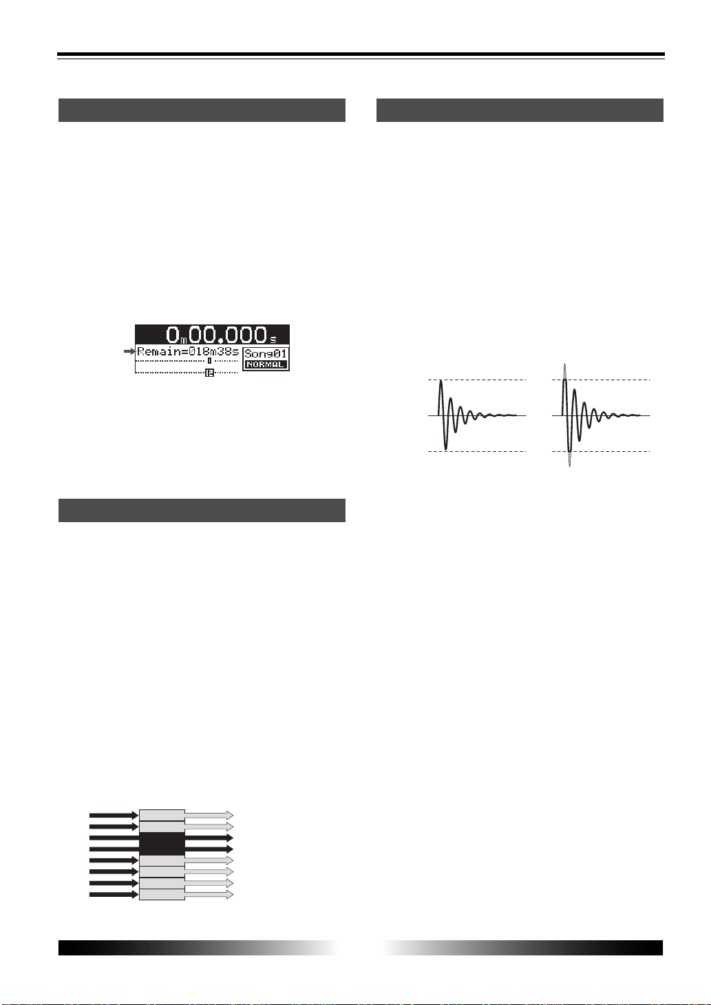
Input monitor and repro monitor
TRIM controlRemain display
"Remain" shows how much time you can further
record audio data to the available space left on
the current CompactFlash
TM
card. As described
earlier, the MR-8 stripes ABS time from
0m00.000s to 60m00.000s at maximum for each
song, however, the remaining time (= available
recording time left) depends on the available
space on the CompactFlash
TM
card. The remain
time is shown as in the screen example below
during recording or record standby. Note that it
shows the remaining time for recording onto a
mono track.
A mono track means a single track. Therefore, to
know the remaining time for recording to more
than one track, divide the displayed time by the
number of tracks. Note that the remaining time
shown on the screen is an approximate time.
Each of the MR-8 tracks has two output modes:
repro monitor and input monitor.
In the repro monitor mode, the track playback
signal is output.
In the input monitor mode, the input signal fed
to the track is output, therefore, you can check
the level of the input signal to be recorded.
To enter a MR-8 track to input monitor mode,
press the appropriate [REC SELECT] key to arm
the track (i.e. make the track record-ready), then
press only the [RECORD] key to enter the
"RECORD READY" mode or press both the
[RECORD] and [PLAY] keys simultaneously to start
recording.
Pay great attention to the TRIM control adjust-
ment.
The signal received at the [INPUT A] or [INPUT
B] jack is routed to the appropriate TRIM con-
trol, by which the signal level fed to the A/D con-
verter of the MR-8 is controlled.
You can check this level by the PEAK indicator. If
the level is too high, the PEAK indicator lights,
while you may hear the sound distorted or noisy.
This distortion (noise) generated at this stage
cannot be eliminated, therefore, adjust the TRIM
control properly so that the PEAK indicator does
not light at the loudest part of the input signal.
Signal input in the recorder
Signal output from the recorder
track 1
track 5
track 6
track 3
READY
track 4
READY
Playback sound (Playback monitor)
Playback sound (Playback monitor)
Playback sound (Playback monitor)
Input signal (Input monitor)
Input signal (Input monitor)
track 2
Playback sound (Playback monitor)
track 7
track 8
Playback sound (Playback monitor)
Playback sound (Playback monitor)
Clip level
Clip level
Appropriate gain Excessive gain
10
MR-8 Owner’s Manual
ENTER
MENU
CURSOR
UNDO
/REDO
CONTRAST
0 RETURN
TIME BASE
SELECT
STORE
B / OUT
A / INPLAY MODE
AUTO PUNCH
RESET
RECORD STOP PLAY
REWIND F FWD
MASTERING
BRIGHTNATURAL
POWERFUL
BOUNCE
1-6 > 7/8
1-4 > 5/6
HALL
DELAY
REC
SELECT
PAN
EFFECT
SEND
INPUT A
L
R
L
R
L
R
L
R
0
10
0
10
0
10
0
10
BRIT STACK US METAL
60's COMBO
DYNAMIC
CONDENSER
TUBE
REVERB / DELAY TIME
MIN
MAX
ROOM
PLATE
MIC SIMULATION
AMP SIMULATION
MIC
BAL
UNBAL
/GUITAR
BAL
UNBAL
MIN
MAX
2
1
R
L
PHONES
STEREO OUT
INPUT A
INPUT B
EFFECT
DISTORTIONTRIM
TRIM
PEAK
LINE MIC
PEAK
LINE MIC
MIN MAX
MASTER
7 / 8
5 / 6432
1
MAX
MIN
MAX
MIN
LOCATE REC END
LOCATE ABS ZERO
DIGITAL MULTITRACKER
-1 +1
LOCATE
7/8 >
+ - _ 0
A B C 1
D E F 2
G H I 3
J K L 4
Y Z 9
V W X 8
S T U 7
P Q R 6
M N O 5
NO
YES
GUITAR
PHONES VOL
INPUT A SELECT
COUNTER
STEREO
WAV FILE
DELETE
A - B PLAY
1
3
8
9
10
13
14
15
16
2
12
11
4
567
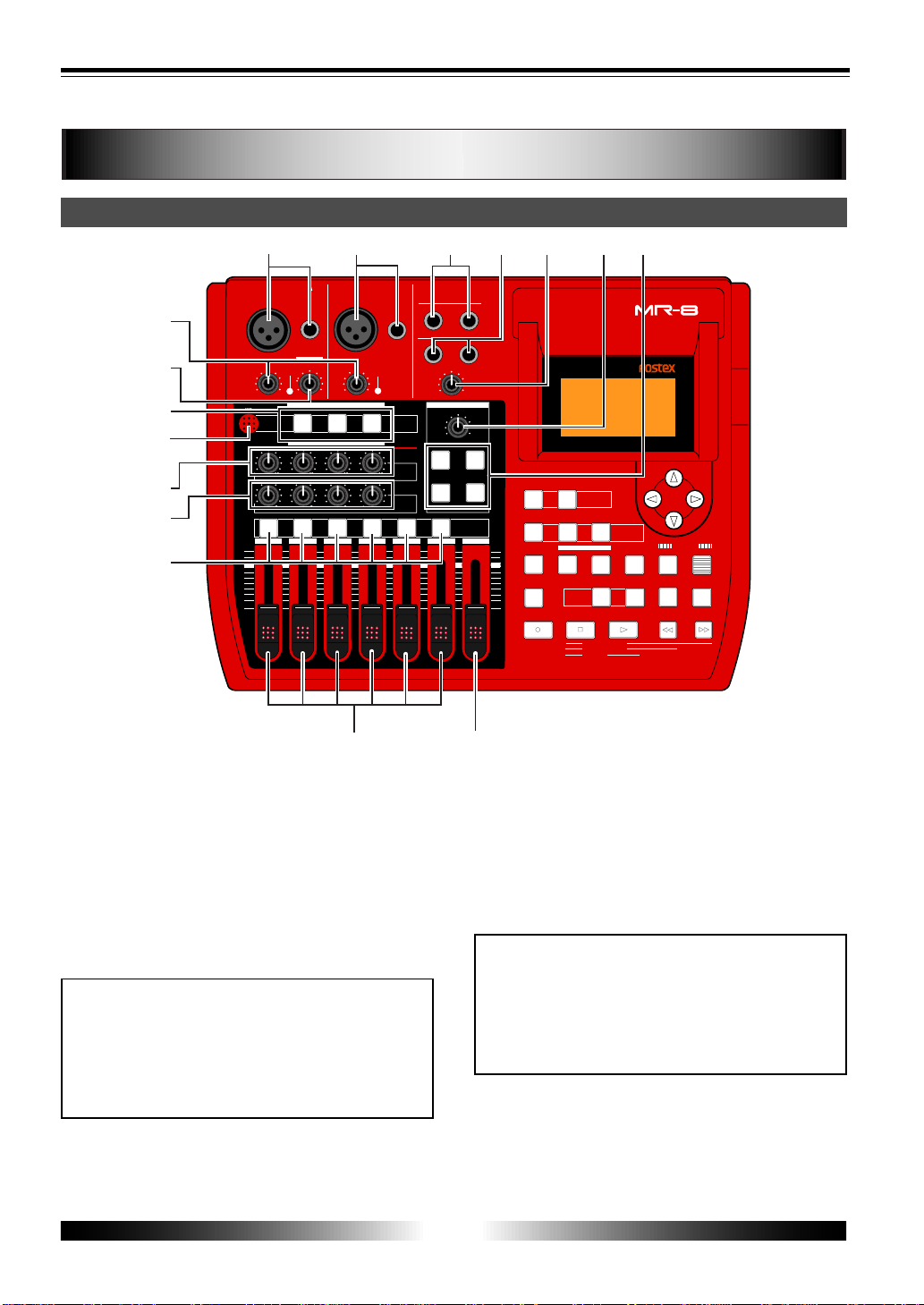
Top panel (left part)
Names and Functions
1. [INPUT A] connector s
Both the [BAL] XLR and [UNBAL/GUITAR] phone
connectors are provided. You can connect a gui-
tar, microphone, keyboard, etc. According to the
source connected, select the [INPUT A SELECT]
switch appropriately.
To record a mono source, use only the [INPUT A]
section. To record a stereo source, use both the
[INPUT A] and [INPUT B] sections (see page 29).
<NOTE>
On each input section, the [UNBAL/GUITAR]
phone connector takes priority to the [BAL]
XLR connector. You cannot use both the
[UNBAL/GUITAR] and [BAL] connectors on the
same section simultaneously.
2. [INPUT B] connector s
Both the [BAL] XLR and [UNBAL] phone connec-
tors are provided. You can connect a micro-
phone, keyboard, etc.
This section is used only when recording a ste-
reo source. When recording a mono source, this
section is not used (see page 29).
<NOTE>
On each input section, the [UNBAL] phone
connector takes priority to the [BAL] XLR con-
nector. You cannot use both the [UNBAL] and
[BAL] connectors on the same section simul-
taneously.
3. [STEREO OUT] jac ks (L, R)
These jacks output the stereo (L and R) buss sig-
nals. Connect these jacks to a monitor equipment
or master recorder (see page 26).

11
MR-8 Owner’s Manual
4. [PHONES] jac ks (1, 2)
Two jacks (1 and 2) are provided. You can use
two pairs of stereo headphones with the MR-8.
5. [PHONES V OL] contr ol
Adjusts the headphone output level.
6. [REVERB/DELA Y TIME] contr ol
Controls the reverb time or delay time (see page
40).
7. [EFFECT] keys
Select the effect type from among ROOM, HALL,
PLATE and DELAY (see page 39).
8. [MASTER] fader
Adjusts the stereo (L and R) buss output level
(see page 32 and 33).
9. Track faders
Each fader adjusts the appropriate track play-
back level. Each of track faders 5/6 and 7/8
controls the appropriate stereo signal (see page
19, 32, and 33).
10.[REC SELECT] keys
Used to select one or two recording tracks.
You can record onto up to two tracks simulta-
neously. Pressing a key arms or unarm the cor-
responding track(s). Tracks 5/6 or 7/8 are armed
or unarmed simultaneously (see page 29, 31, and
33).
11.[P AN] contr ols
Control panning for tracks 1 through 4 (see page
45).
12.[EFFECT SEND] controls
Control the amount of signals from tracks 1
through 4 sent to the internal effect (reverb/de-
lay). (see page 40).
13.Internal microphone
You can make recording using the internal mi-
crophone by setting the [INPUT A SELECT] switch
on the rear panel to "INT MIC" (see page 29).
14.Insert effect select keys
Used to select the insert effect (mic simulation
or amp simulation) for the signal from the [IN-
PUT A] jack.
When setting the [INPUT A SELECT] switch on
the rear panel to "MIC/LINE", you can use the
mic simulation effect. When setting the switch to
"GUITAR", you can use the amp simulation ef-
fect (see page 30 and 38).
15.[DISTORTION] contr ol
Controls the amount of the distortion effect for a
guitar connected to the phone jack on the [IN-
PUT A] section.
This control is effective only when the [INPUT A
SELECT] switch is set to "GUITAR" (see page 30).
16.[TRIM] controls
Control the input gain of the [INPUT A] and [IN-
PUT B] sections (see page 30).
12
MR-8 Owner’s Manual
ENTER
MENU
CURSOR
UNDO
/REDO
CONTRAST
0 RETURN
TIME BASE
SELECT
STORE
B / OUT
A / INPLAY MODE
AUTO PUNCH
RESET
RECORD STOP PLAY
REWIND F FWD
MASTERING
BRIGHTNATURAL
POWERFUL
BOUNCE
1-6 > 7/8
1-4 > 5/6
HALL
DELAY
REC
SELECT
PAN
EFFECT
SEND
INPUT A
L
R
L
R
L
R
L
R
0
10
0
10
0
10
0
10
BRIT STACK US METAL
60's COMBO
DYNAMIC
CONDENSER
TUBE
REVERB / DELAY TIME
MIN
MAX
ROOM
PLATE
MIC SIMULATION
AMP SIMULATION
MIC
BAL
UNBAL
/GUITAR
BAL
UNBAL
MIN
MAX
2
1
R
L
PHONES
STEREO OUT
INPUT A
INPUT B
EFFECT
DISTORTIONTRIM
TRIM
PEAK
LINE MIC
PEAK
LINE MIC
MIN MAX
MASTER
7 / 8
5 / 6432
1
MAX
MIN
MAX
MIN
LOCATE REC END
LOCATE ABS ZERO
DIGITAL MULTITRACKER
-1
+1
LOCATE
7/8 >
+ - _ 0
A B C 1
D E F 2
G H I 3
J K L 4
Y Z 9
V W X 8
S T U 7
P Q R 6
M N O 5
NO
YES
GUITAR
PHONES VOL
INPUT A SELECT
COUNTER
STEREO
WAV FILE
DELETE
A - B PLAY
17
19 20 21
22
23
24
25
26
27
28
29
3031
32
33
18
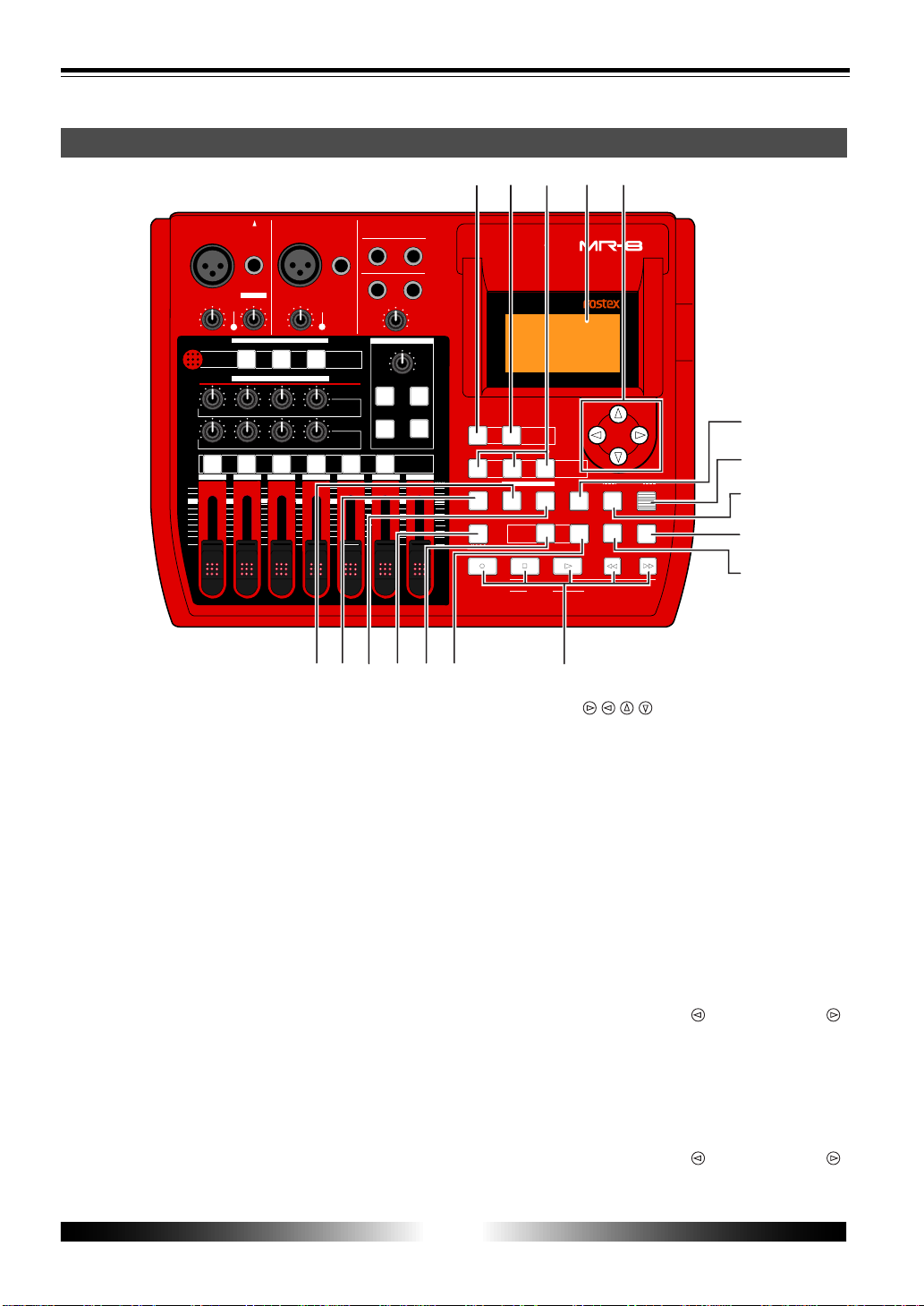
Top panel (right part)
17.[1-4 > 5/6, 1-6 > 7/8] / [DELETE] key
Selects the bounce mode (see page 43).
Each press of the key alternates "1-4 > 5/6" and
"1-6 > 7/8". In the menu mode, this key is also
used for deleting a character in a song name (see
page 58).
18.[7/8 > STEREO W AV FILE] key
Converts a mono WAV file recorded on tracks 7/
8 to a stereo WAV file (see page 86).
You can export the stereo WAV file to your per-
sonal computer over the USB connection (see
page 88).
19.[MASTERING] keys
Used to select the mastering effect during track
bounce or mixdown (see page 41).
In the menu mode, the [POWERFUL] key is used
for character entry of +, -, _, and 0 (see page 21).
20.LCD display
This 128 x 64 dot LCD display shows various in-
formation (see page 27).
21.[CURSOR / / / ] keys
Used to move the cursor in the menu mode, ex-
ecute/cancel settings, etc.
22.[STORE] / J K L 4 entry key
Stores the current recorder position (timedata)
as the LOCATE A/IN or LOCATE B/OUT point (see
page 36 and 53). In the menu mode, this key is
used for character entry of J (j), K (k), L (l) and 4
(see page 21).
23.[ENTER] / [CONTRAST] key
Confirms the selection in the menu mode.
While holding down this and the [MENU] key
together, you can adjust the LCD display con-
trast by using the [CURSOR
] and [CURSOR ]
key (see page 28).
24.[MENU] / [CONTRAST] key
Enters the menu mode.
While holding down this and the [ENTER] key
together, you can adjust the LCD display con-
trast by using the [CURSOR
] and [CURSOR ]
key (see page 28).

13
MR-8 Owner’s Manual
25.[UNDO/REDO] / Y Z 9 entry key
Used to undo or redo recording or editing (see
page 32 and 34). Each press of the key alternates
"undo" and "redo". In the menu mode, this key
is used for character entry of Y (y), Z (z) and 9
(see page 21).
26. [TIME BASE SELECT] / V W X 8 entry key
Selects the time base shown on the LCD display
(see page 27). Pressing this key while holding
down the [MENU] and [ENTER] keys together
resets the LCD display contrast to the default
value (see page 28). In the menu mode, this key
is used for character entry of V (v), W (w), X (x)
and 8 (see page 21).
27. T ransport keys
[PLA Y] ke y
Starts playback of the recorder.
Pressing this key while holding down the
[RECORD] key starts recording of the armed
(record-ready) track(s). Pressing this key dur-
ing recording releases recording.
[STOP] key
Stops the recorder.
By pressing the [PLAY], [REWIND] or [F FWD] key
while holding down the [STOP] key, you can lo-
cate to a specific point or repeat playback as be-
low.
• [STOP] + [PLAY] (A-B PLAY)
Repeats playback between the LOCATE A and
LOCATE B points (see page 49).
• [STOP] + [REWIND] (LOCATE ABS ZERO)
Locates to the beginning (ABS ZERO) of the current
song (see page 52).
• [STOP] + [F FWD] (LOCATE REC END)
Locates to the recording end of the current song
(REC END) (see page 52).
[RECORD] key
Pressing the [PLAY] key while holding down the
[RECORD] key starts recording of the armed
(record-ready) track(s) (see page 32 and 34).
By pressing only the [RECORD] key when any
track(s) is armed (in record-ready), the input
signal(s) of the armed track(s) can be monitored
(i.e. input monitor mode).
[F FWD] key
Pressing this key fast forwards the recorder.
During playback, pressing this key starts 3 x cue-
ing. While holding down the [STOP] key, press-
ing this key locates to the recording end of the
current song (REC END) (see page 52).
While holding down the [ENTER] key, pressing
this key selects a song (see page 24).
[REWIND] key
Pressing this key rewinds the recorder.
During playback, pressing this key starts 3 x re-
verse cueing. While holding down the [STOP]
key, pressing this key locates to the beginning
(ABS ZERO) of the current song (see page 52).
While holding down the [ENTER] key, pressing
this key selects a song (see page 24).
28. [COUNTER 0 RETURN] / S T U 7 entry key
Locates to the counter zero point (see page 53).
In the menu mode, this key is used for character
entry of S (s), T (t), U (u) and 7 (see page 21).
29. [COUNTER RESET] / P Q R 6 entry key
Resets the counter to zero (see page 52). In the
menu mode, this key is used for character entry
of P (p), Q (q), R (r) and 6 (see page 21).
30.[AUT O PUNCH] / M N O 5 entry ke y
Turns on or off the auto punch mode (see page
36). In the menu mode, this key is used for char-
acter entry of M (m), N (n), O (o) and 5 (see page
21).
31. [LOCATE B/OUT] / G H I 3 entry key
Pressing the [STORE] key followed by this key
stores the LOCATE B (or punch out) point (see
page 36 and 53). In the menu mode, this key is
used for character entry of G (g), H (h), I (i) and
3 (see page 21).
32. [LOCATE A/IN] / D E F 2 entry key
Pressing the [STORE] key followed by this key
stores the LOCATE A (or punch in) point (see
page 36 and 53). In the menu mode, this key is
used for character entry of D (d), E (e), F (f) and
2 (see page 21).
33. [PLAY MODE] / A B C 1 entry key
Selects the play mode from among normal, auto
play, auto return and loop (see page 50).
In the menu mode, this key is used for charac-
ter entry of A (a), B (b), C (c) and 1 (see page 21).
14
MR-8 Owner’s Manual
MIC/LINE
GUIT AR
INT MIC
DC IN
POWER
USB
FOOT SW
DIGITAL
OUT
INPUT A SELECT
MIC/LINE
INT MIC
GUITAR
LIGHT
12V
ON
OFF
[NORMAL MODE]
12
3
4
5
6
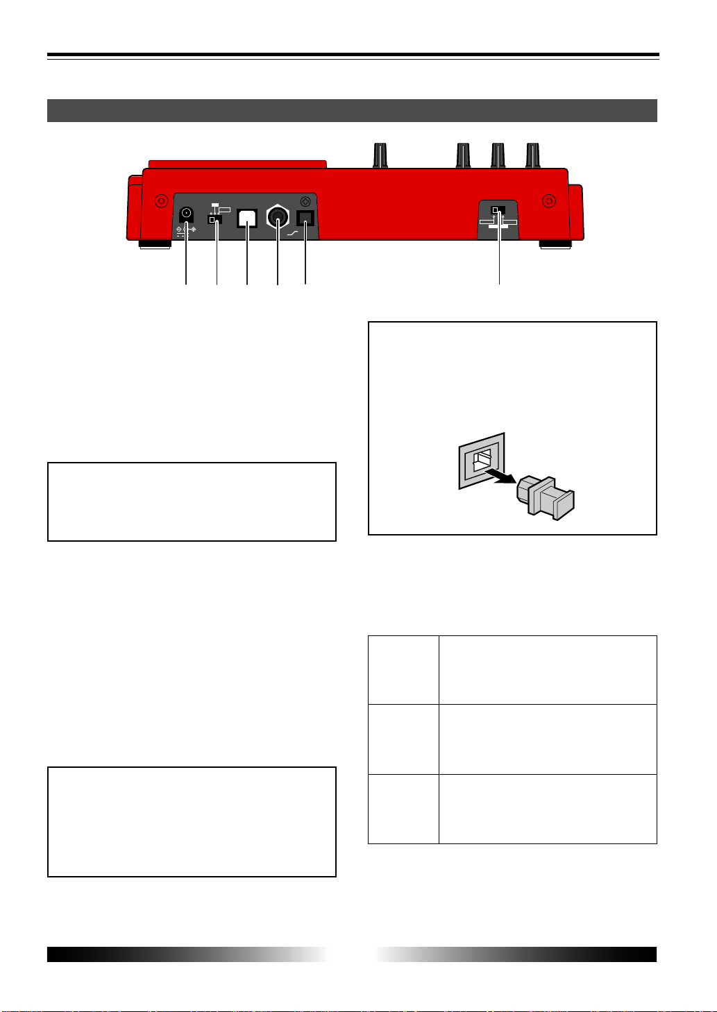
Rear panel
1. [DC IN] jack
Connect the supplied AC adaptor to this jack (see
page 17).
2. [PO WER] switc h
Used to turn on or off the power.
By setting the switch to "LIGHT", the backlight of
the LCD display lights up (see page 18).
<Note>
When driving the MR-8 by batteries, we rec-
ommend not to use the backlight, because
the batteries are exhausted quickly.
3. [USB] port
Used to connect with a personal computer using
a standard USB cable (see page 88).
4. [FOO T SW] jack
Used to connect with the optional footswitch
(Model 8051) or an unlatched-type footswitch
(see page 35).
5. [DIGITAL OUT] connector
Used to connect with an external digital device
(see page 48).
<Note>
Only song data created by the normal mode
(44.1 kHz, 16 bit) can be digitally output from
this port.
Song data created by the extended mode can-
not be digitally output.
6. [INPUT A SELECT] switc h
This switch must be set appropriately according
to the input source of the [INPUT A] section (see
page 29).
Set the switch to this position when the source
is an external microphone or line level source.
Both the [BAL] XLR and [UNBAL/GUITAR]
phone connectors can be used.
Set the switch to this position when the source
is a guitar connected to the phone connector.
Both the [BAL] XLR and [UNBAL/GUITAR]
phone connectors can be used.
Set the switch to this position when the source
is the built-in microphone.
Both the [BAL] XLR and [UNBAL/GUITAR]
phone connectors cannot be used.
<Note>
When you open the MR-8 carton, the protec-
tion cap is inserted to the [DIGITAL OUT] con-
nector. When using the connector, remove
the cap. When no connection is made to the
connector, keep the cap inserted.
15
MR-8 Owner’s Manual
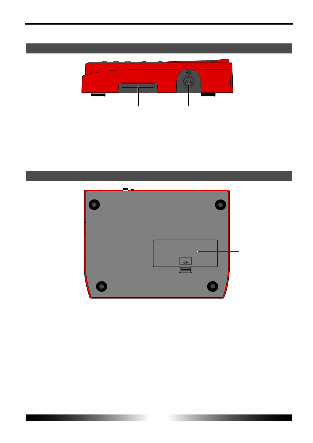
Bottom panel
COMPACT FLASH CARD
MIDI OUT
1
2
Side panel
OPEN
1
1. Card slot
A CompactFlash
TM
card is inserted to this slot (see
page 16).
2. [MIDI OUT] jac k
Used to connect to a [MIDI IN] jack of an external
MIDI device (such as a MIDI sequencer) (see page
77).
1. Battery compartment
To use the MR-8 with batteries, insert six stan-
dard alkaline AA-type batteries to this compart-
ment (see page 17).
16
MR-8 Owner’s Manual
COMPACTFLASH CARD
COMPACT FLASH CARD
MIDI OUT
Slot
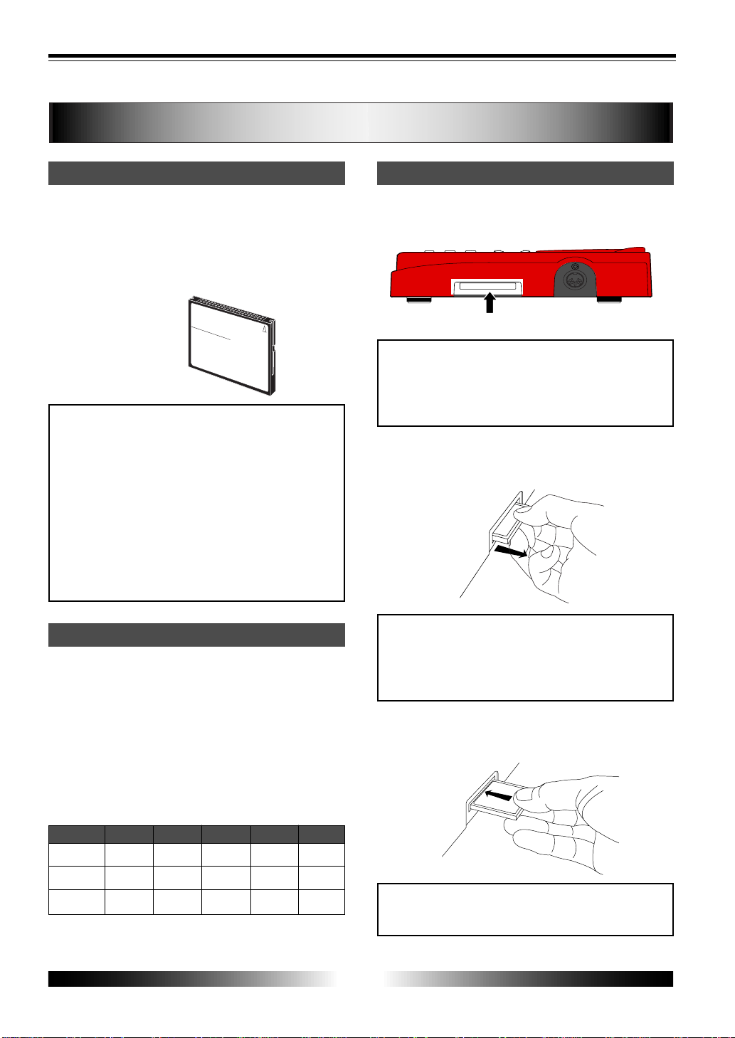
Recording time
Inserting a CompactFlash
TM
cardCompactFlash
TM
card
How to remove a CompactFlash
TM
card
Place your fingertip in the groove under the card
and pull it forward.
Mono
128MB
256MB
512MB
<Image>
Memory size
About recording medium
The MR-8 uses a CompactFlash
TM
card (see the
illustration below) as a recording medium.
On the CompactFlash
TM
card supplied with the
unit, a demo song is recorded. See "Playing back
the demo song" on page 19 for details about how
to play back the demo song.
<Note>
When using a CompactFlash
TM
card other than
the supplied one, make sure that the card is
tested and confirmed by Fostex. If you use a
card which is not tested and confirmed by
Fostex, the MR-8 may not work correctly. About
cards confirmed by Fostex, see the Fostex web
site or contact your nearest Fostex dealer or
service station. Also note that, before using a
new card, you must format the card by the
MR-8 (see page 22).
The available recording time depends on the
memory size of the card used. The following
table shows the approximate recording time when
recording in the normal mode (at 44.1-kHz, 16-
bit), as well as in the extended mode (at 22.05-
kHz, 16-bit). Refer to this table when purchas-
ing a CompactFlash
TM
card. We recommend to
use a CompactFlash
TM
card whose memory size
is more than 128 MB.
24 (48)
Insert a CompactFlash
TM
card to the slot on the
right side panel. (When shipped, the supplied
card is inserted.)
<Important!>
When inserting or removing a card,
make sure that the power of the MR-8 is off. If you
insert or remove a card when the power is on, the
card may be damaged or the recorded data may be
lost.
<Important!>
Do not leave a CompactFlash
TM
card
in a dusty place, a place where static electricity is
easily generated, or a place where is affected by mag-
netic fields. Also, do not give a strong impact or ex-
cessive power.
How to insert a CompactFlash
TM
card
With the surface side up, insert a card until it
cannot go further.
<Important!>
• Do not insert a card in the wrong direction.
• Do not push a card with excessive force.
* Minutes in parenthesis: extended mode
48 (96)
96 (193)
2TR
12 (24)
24 (48)
48 (96)
4TR
6 (12)
12 (24)
24 (48)
6TR
4 (8)
8 (16)
16 (32)
8TR
3 (6)
6 (12)
12 (24)
Approx. Minutes
17
MR-8 Owner’s Manual
DC IN
POWER
USB
FOOT SW
DIGITAL
OUT
LIGHT
12V
ON
OFF
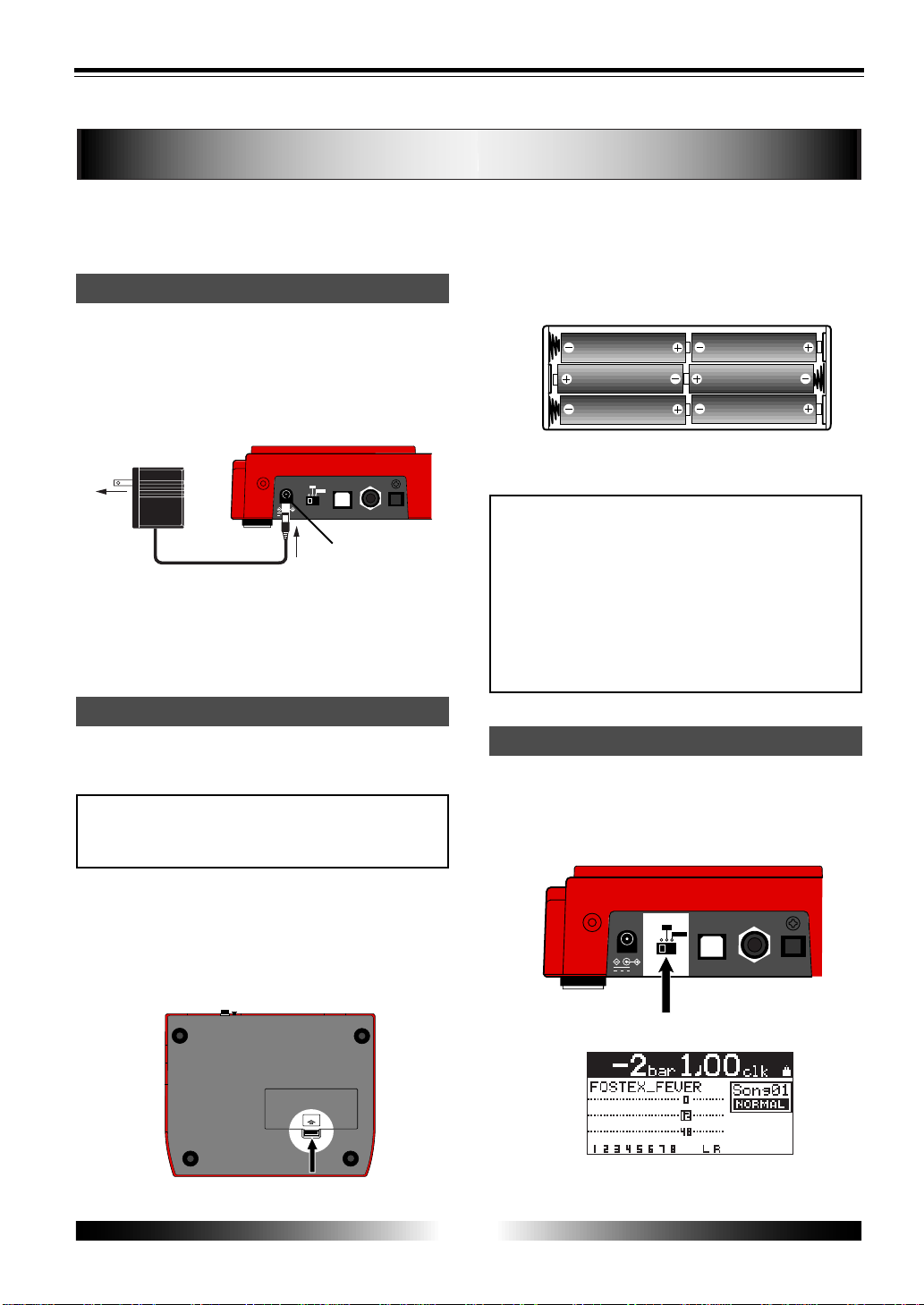
T urning on the unit
OPEN
Connecting the AC adaptor
Inserting batteries
DC IN
POWER
USB
FOOT SW
DIGITAL
OUT
LIGHT
12V
ON
OFF
The beginning of the demo song is shown.
[POWER] switc h
Model AD-12A
[DC IN] connector
About the power
You can use the MR-8 either with the supplied AC adaptor (Model AD-12A) or alkaline
batteries (AA-type x 6, not supplied with the MR-8). When preparing the power source,
make sure that the [POWER] switch of the MR-8 is set to off.
See the illustration below.
Connect the plug of the supplied AC adaptor to
the [DC IN] jack firmly, then connect the AC adap-
tor to the AC main outlet. Make sure that the
voltage of your AC outlet matches the supplied
AC adaptor's specification.
The battery compartment is located at the bot-
tom of the MR-8.
To insert batteries, follow the procedure below.
<Important!>
No battery is supplied with the unit.
Purchase AA-type alkaline batteries. Do not use
manganese batteries.
1. Put the MR-8 with the bottom panel up on soft
material such as cloth.
2. Push the tab on the battery compartment cover to
the direction shown by arrow in the illustration
below, and remo ve the cover.
3. Insert six batteries in the right direction as shown
below.
4. Place the compartment cover to the original
position.
<Notes for changing batteries>
• Do not leave the exhausted batteries in the bat-
tery compartment.
• When batteries are exhausted, remove them from
the battery compartment. If you leave them, chemi-
cal liquid in the batteries may leak out and damage
the unit. If you do not use the unit with batteries for
a long time, remove the batteries even though they
are new.
• Never mix old and new batteries.
The first time you turn on the power, the LCD
display shows the startup screen, followed by the
screen below showing that the demo song is
loaded. See page 27 for details about screens.
When the AC adaptor is connected while batter-
ies are installed, the power is supplied to the MR-
8 from the AC adaptor. If the AC adaptor is un-
plugged, the batteries supply the power to the
MR-8.
18
MR-8 Owner’s Manual
T urning off the po wer
T urning on the LCD displa y backlight
Low battery display
flashing
POWER
LIGHT
ON
OFF
LIGHT position
If the LCD display does not show the startup
screen when turning on the power, check the
following.
• The power is supplied to the unit. (i.e. the AC
adaptor is correctly connected, or batteries are
not exhausted and correctly set.)
• The card is correctly set to the slot.
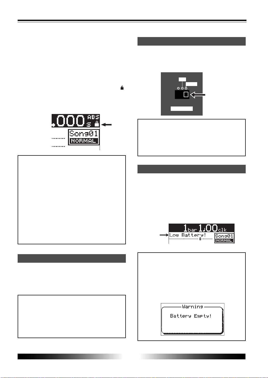
Note that the demo song is protected and the " "
icon is shown at the top right of the screen.
You can play back a protected song but cannot
make recording or edit data. See page 20 for the
details.
<Important!>
Note when external devices are connected.
If external devices are connected to the MR-8,
follow the procedure below when turning on
the power.
1. Turn down the MR-8 [MASTER] fader.
2. Turn on the power of source devices.
3. Turn on the power of the MR-8.
4. Turn on the power of monitor devices (such
as an amplifier, speakers with built-in
amplifiers, etc.).
When turning off the power, make sure that the
MR-8 is stopped. If external devices are con-
nected, reverse the procedure shown above (i.e.
monitor devices -> MR-8 -> source devices).
<Important!>
If you turn off the MR-8 power while the card is
accessed, the recorded songs or card itself may be
damaged.
You do not have to shut down the MR-8 before
turning it off. All data recorded before turning off
the power are memorized.
If you hardly see the screen on the LCD display
in the dark place, turn the LCD display backlight
by setting the [POWER] switch to the "LIGHT"
position.
<Note>
When using the MR-8 with batteries, we recommend
not to turn on the backlight except when it is needed.
Turning on the backlight consumes the battery
power, therefore, the operation time becomes
shorter.
When using the MR-8 with batteries and the bat-
tery power becomes low, "Low Battery!" flashes
on the display.
If you see this, interrupt the current work and
replace batteries.
Note that when "Low Battery!" flashes on the dis-
play, you cannot turn on the backlight.
<Important!>
If you continue your work after "Low Battery!" starts
flashing, the batteries finally become empty. In
such a condition, the warning message as shown
below appears on the display and the MR-8 does
not accept any key operation.
We recommend to replace batteries as soon as "Low
Battery!" starts flashing.
19
MR-8 Owner’s Manual
ENTER
MENU
CURSOR
UNDO
/REDO
CONTRAST
0 RETURN
TIME BASE
SELECT
STORE
B / OUT
A / INPLAY MODE
AUTO PUNCH
RESET
RECORD STOP PLAY
REWIND F FWD
MASTERING
BRIGHTNATURAL
POWERFUL
BOUNCE
1-6 > 7/8
1-4 > 5/6
HALL
DELAY
REC
SELECT
PAN
EFFECT
SEND
INPUT A
L
R
L
R
L
R
L
R
0
10
0
10
0
10
0
10
BRIT STACK US METAL
60's COMBO
DYNAMIC
CONDENSER
TUBE
REVERB / DELAY TIME
MIN
MAX
ROOM
PLATE
MIC SIMULATION
AMP SIMULATION
MIC
BAL
UNBAL
/GUITAR
BAL
UNBAL
MIN
MAX
2
1
R
L
PHONES
STEREO OUT
INPUT A
INPUT B
EFFECT
DISTORTIONTRIM
TRIM
PEAK
LINE MIC
PEAK
LINE MIC
MIN MAX
MASTER
7 / 8
5 / 6432
1
MAX
MIN
MAX
MIN
LOCATE REC END
LOCATE ABS ZERO
A - B PLAY
DIGITAL MULTITRACKER
-1
+1
LOCATE
7/8 >
+ - _ 0
A B C 1
D E F 2
G H I 3
J K L 4
Y Z 9
V W X 8
S T U 7
P Q R 6
M N O 5
NO
YES
GUITAR
PHONES VOL
INPUT A SELECT
COUNTER
STEREO
WAV FILE
1
2
[POWER] SW
3
3, 5
46
5
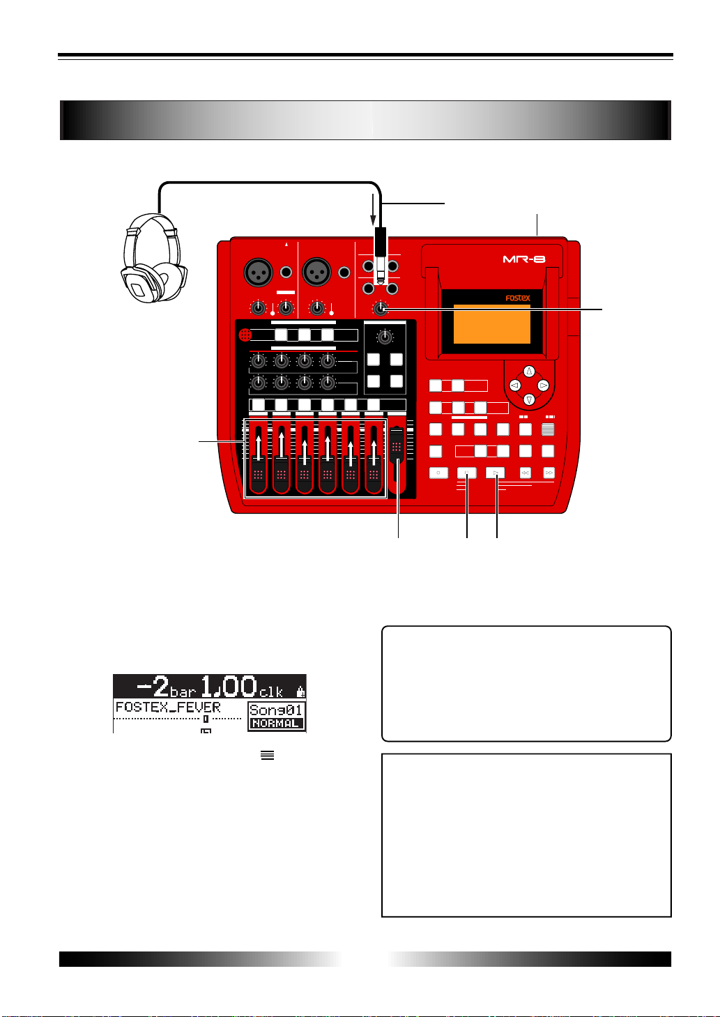
Listening the demo song
A demo song is recorded on the supplied CompactFlash
TM
card. Let's listen to this song.
1) Connect headphones or a monitor system to the
MR-8.
2) Set the [POWER] s witch to ON.
The MR-8 turns on the power. After the LCD
display shows the startup screen, the demo song
(Song 01: FOSTEX_FEVER) is loaded.
Tips: Listening to the demo song again
When the recorder is stopped after listening to the
demo song, press the [REWIND] key while holding
down the [STOP] key. The recorder instantly moves
back to the beginning of the demo song.
Then pressing the [PLAY] key starts playback from
the beginning of the demo song.
<Note>
To record a new material onto the supplied card,
you have to delete the demo song.
If you wish to keep the demo song, you cannot record
a material onto the supplied card, therefore, you
must record a material onto a new CompactFlash
TM
card.
Before recording a material onto a new card, you
must make preparations for a card. See "Prepara-
tions of a CompactFlash
TM
card" on the next page.
6) When the demo song ends, press the [ST OP] ke y
to stop the recorder .
3) Raise the [MASTER] fader to the " " position.
Do not raise the track faders at this stage.
4) Press the [PLAY] key to start playback.
5) Raise the track faders gradually to adjust the pla y
back level.
If you are using headphones for monitoring, also
raise the [PHONES] control gradually to adjust the
headphones level. (If you are using a monitor
amplifier/speaker system for monitoring, adjust the
level control of the amplifier.)
20
MR-8 Owner’s Manual
Preparation for recording onto the supplied card
flashing
After playing back the demo song, let's make preparations for a CompactFlash
TM
card onto
which you are going to record. Depending on whether you are going to record a material
onto the supplied CompactFlash
TM
card or a new card, make either of the following prepara-
tions.
Before recording a material onto the supplied
card, you must release the protection of the demo
song and delete the demo song, then create a
new song on the card.
1) Make sure that the supplied card is set to the slot,
then turn on the MR-8 power .
The recorded demo song is loaded.
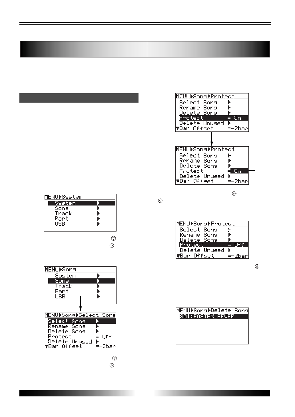
2) Press the [MENU] key to enter the menu mode.
The LCD display shows the MENU screen. The
first time you access to this screen, "System"
is highlighted.
3) Highlight "Song" using the [CURSOR
] key , then
press the [ENTER] key (or [CURSOR
] key).
The display now shows the song edit menu
screen. Initially, "Select Song" is highlighted.
4) Highlight "Protect" using the [CURSOR ] key, then
press the [ENTER] key (or [CURSOR
] key).
"On" (default) starts flashing.
5) Select "Off" using the [CURSOR
] or [CURSOR
] key , then press the [ENTER] key.
The protection is released, and the screen now
looks like the following.
6) Highlight "Delete Song" using the [CURSOR
] key ,
then press the [ENTER] key .
The display shows the screen on which you
can select a song to be deleted.
On the supplied card, only one song (S01:
FOSTEX_FEVER) is shown.
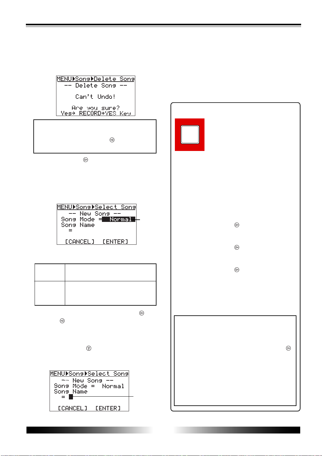
7) While "S01: FOSTEX_FEVER" is highlighted, press
the [ENTER] key .
The display shows the confirmation screen for
deleting a song.
Preparation of a CompactFlash card
TM
21
MR-8 Owner’s Manual
Normal
Extended
PLAY MODE
A B C 1
flashing
<Note>
You cannot undo song deletion. To cancel delet-
ing a song, press the [CURSOR ] key when the
confirmation screen is shown.
8) Press the [CURSOR ] key while holding down the
[RECORD] key .
The demo song is deleted, while the display
now shows the screen for newly creating song
01, in which you can select the song mode
(initially, "Normal" is flashing).
You can select between "Normal" and "Ex-
tended".
Fs 44.1 kHz, 16-bit high quality audio mode.
Normally, select this option.
Fs 22.05 kHz, 16-bit long time mode.
Song data recorded in this mode cannot be
digitally output.
9) Select the song mode using the [CURSOR ] or
[CURSOR
] key , then press the [ENTER] ke y.
Now the song mode is set and the selected
option steadily lights.
10) Press the [CURSOR ] key.
The cursor moves to the first character entry
position of a song name.
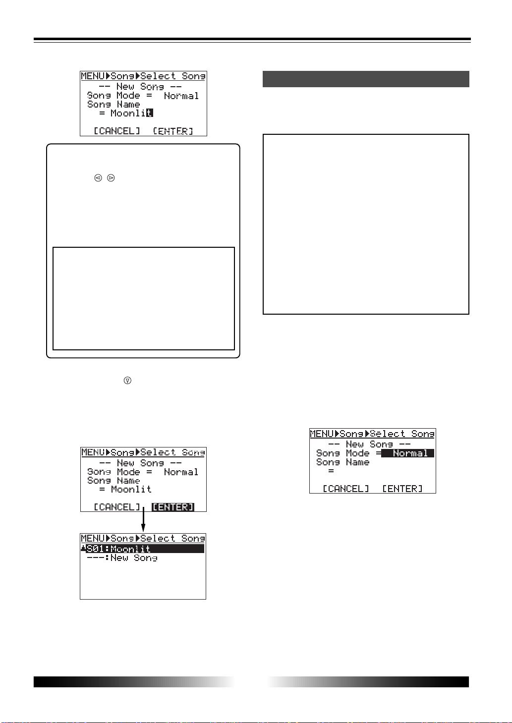
11) Enter a desired character using the character
entry keys together with [CURSOR] keys.
See below for details about how to enter
characters. You can enter up to 16 characters.
You must enter a song name, otherwise, you
cannot create a song.
<How to enter characters>
<Character entry keys>
Some keys on the MR-8 top panel
act as character entry keys in the
menu mode. For example, the
[PLAY MODE] key (shown at the
left) can be used for entering A,
B, C, a, b, c and 1.
Each press of a character entry key switches
the character to be entered from among those
assigned to the key.
<Entry example>
The following procedure shows how to enter
"Moonlit" as a song name.
1. Use the [AUTO PUNCH] key to enter "M".
2. Press the [CURSOR
] key to move the
cursor right.
3. Use the [AUTO PUNCH] key to enter "o".
4. Press the [CURSOR
] key to move the
cursor right.
5. Use the [AUTO PUNCH] key to enter "o".
6. Press the [CURSOR
] key to move the
cursor right.
7. Use the [AUTO PUNCH] key to enter "n".
8. Use the [STORE] key to enter "l".
9. Use the [LOCATE B/OUT] key to enter "i".
10. Use the [0 RETURN] key to enter "t".
<Notes on cursor movement>
Pressing a different character entry key automati-
cally moves the cursor right.
If two successive characters are assigned to the
same character entry key, press the [CURSOR ]
key after selecting the first character to move
the cursor right.
Also note that you cannot use “+” for a song name
with less than 9 characters. For example, you
cannot enter “AAA+BBB” for a song name.
You can use “+” for a song name with 8 or more
characters. For example, you can enter
“AAA+BBBBB”.
In this screen, “Delete Song” and “Can’t Undo”
are shown for warning, as well as
“Yes->RECORD+YES Key” and “No->NO Key”
alternately flash.
flashing
22
MR-8 Owner’s Manual
Preparation for recording onto a new car d
<Correction and deletion>
To correct a character entered, use the
[CURSOR
/ ] keys to move the cursor to
the character you want to correct, and re-
enter the desired character.
By moving the cursor to the last character
and pressing the [1-4>5/6, 1-6>7/8] key
repeatedly, you can delete all characters.
<Note>
You have to enter a song name. If you go to
the next operation without entering a song
name, the warning message appears and the
display shows the song name entry screen. If
you enter a song name which is already used
in the card, the same warning message ap-
pears. You can change a song name whenever
you like in the menu mode (see page 58).
12) Highlight “[ENTER]” at the bottom of the screen
using the [CURSOR
] key , and press the [ENTER]
key .
The screen changes to show the Song menu
screen. To cancel creating a song, highlight
“[CANCEL]” and press the [ENTER] key in the
step above.
13) Press the [MENU] key to quit the menu mode.
To create another song, follow the same
procedure above. You can also delete an
unnecessary song (see page 59).
Before recording a material onto a new card
(which is operation-confirmed by Fostex), carry
out the following procedure for preparation.
<Note>
You can use a card which has been used with
a digital camera or personal computer if the
card is operation-confirmed. However, de-
pending on the use of the card, the remain-
ing space for recording with the MR-8 may be
small. Therefore, we recommend to format
the card by your digital camera or personal
computer before using it with the MR-8.
If you cannot format such a card with another
device, you can format the card with the MR-
8 using the "Card Format" menu after creat-
ing a new song by the following procedure.
See page 25 for formatting a card with the
MR-8.
1) While the MR-8 power is off, remo ve the supplied
card from the slot and insert a new card to the slot.
2) T urn on the MR-8 power.
After showing the startup screen, the display
automatically shows the "Select Song" screen
of the Song menu, on which you can create
song 01.
As described earlier, set the song mode (Nor-
mal or Extended) and song name to create song
01.
After creating a song, you can make recording
onto the card.
23
MR-8 Owner’s Manual
Creating a song
flashing
This section describes how to create a new song on a card and how to select a desired song
among more than one song created.
In the following procedure, we assume that song
1 (S01) is already created on the card and we are
going to created a new song.
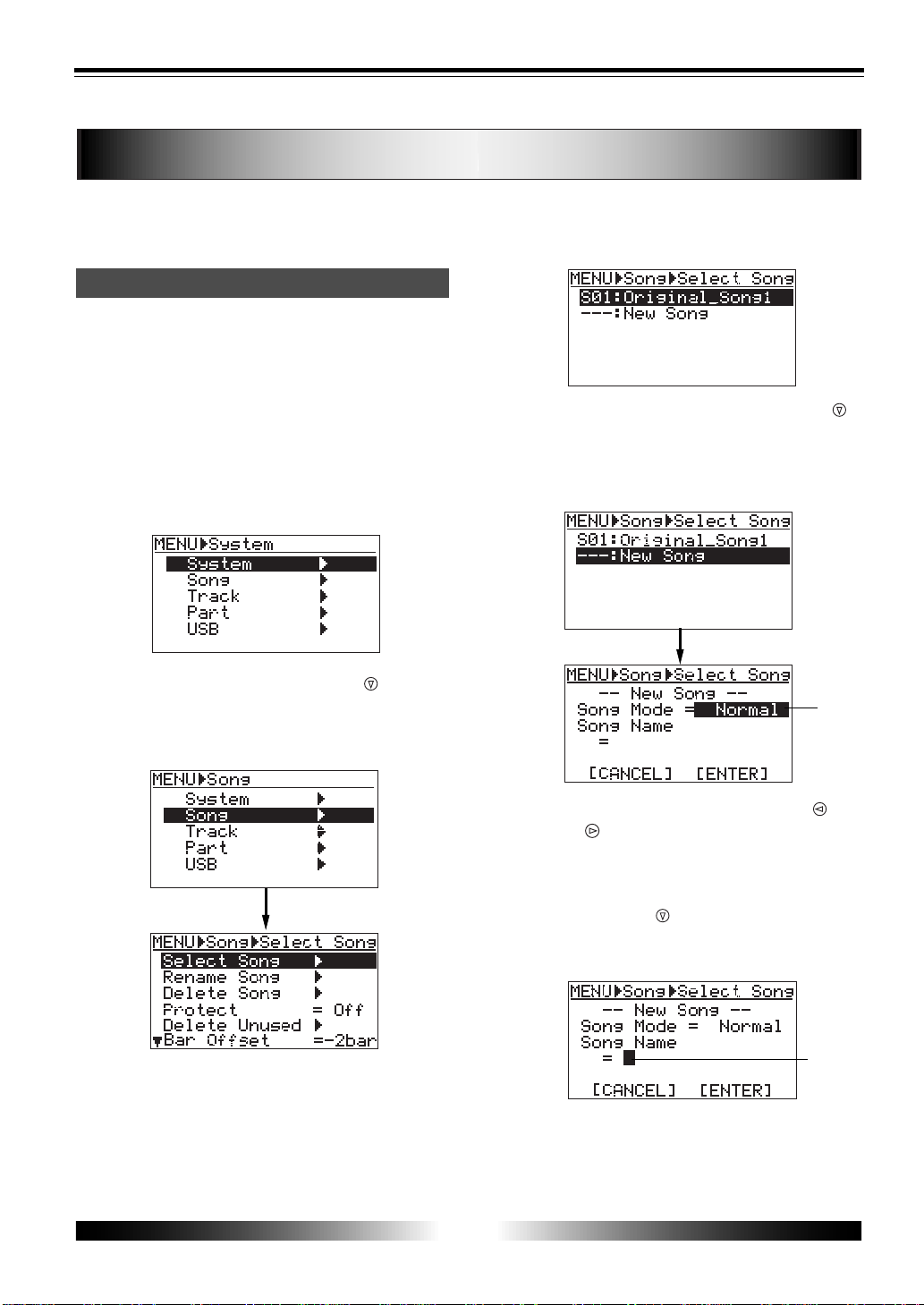
1) While the recorder is stopped, press the [MENU]
key to enter the menu mode.
The LCD display shows the MENU screen. The
first time you access to this screen, "System"
is highlighted.
2) Highlight "Song" using the [CURSOR
] key , then
press the [ENTER] key .
The display now shows the song edit menu
screen. Initially, "Select Song" is highlighted.
3) While "Select Song" is highlighted, press the
[ENTER] key .
Song 01 (S01: Original Song1) already created
is highlighted, while "---:New Song" is shown
on the next line.
4) Highlight "---:New Song" using the [CURSOR
]
key , then press the [ENTER] key.
The display now shows the screen on which
you can select the song mode of the new song
you are going to create.
5) Select the song mode using the [CURSOR
] or
[CURSOR ] key.
You can select between "Normal" and
"Extended".
6) Press the [CURSOR ] key .
The cursor (flashing point) moves to the first
character entry position of a song name.
7) Enter a desired name following the same
procedure as described on page 21.
Creating a song/selecting a song
flashing
24
MR-8 Owner’s Manual
Selecting a desired song
[ENTER] key
[F FWD] key
[REWIND] key
ENTER
MENU
CURSOR
UNDO
/REDO
CONTRAST
0 RETURN
TIME BASE
SELECT
STORE
PLAY
REWIND F FWD
MASTERING
-1
+1
J K L 4
Y Z 9
V W X 8
S T U 7
NO YES
8) After completing song name entry, use the
[CURSOR
] key to move the cursor to "ENTER"
at the bottom of the screen, then press the
[ENTER] key .
The screen now shows the song list in which
you see the new song added.
To cancel creating a song, use the [CURSOR
] key to move the cursor to "[CANCEL]"
(instead of "[ENTER]"), then press the [ENTER]
key.
9) Press the [MENU] key to quit the menu mode.
To create another song, follow the same proce-
dure above. You can also delete an unnecessary
song (see page 59).
If more than one song is created on a card, you
have to select a desired song first by following
the procedure below.
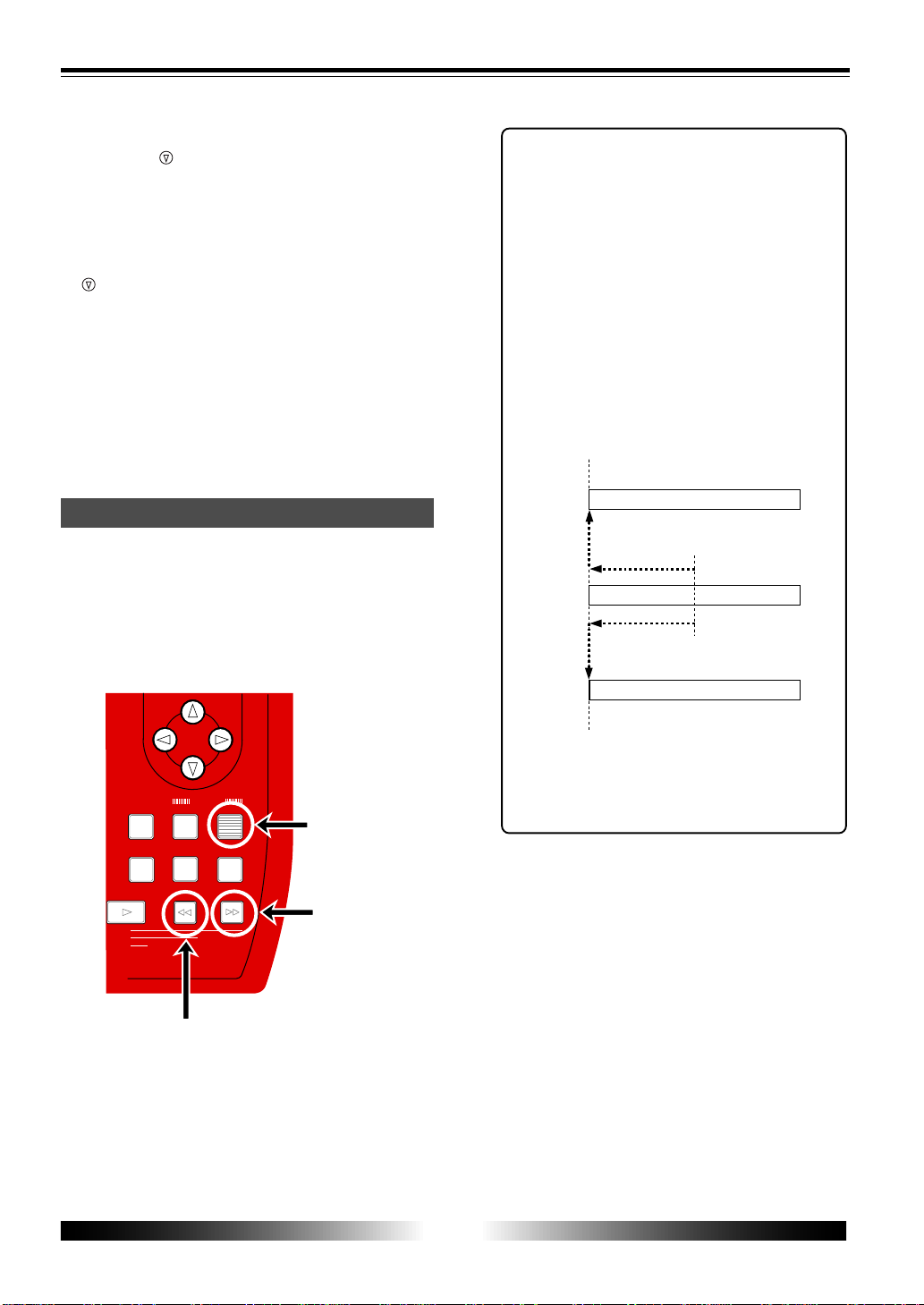
1) When the display shows the home screen and the
recorder is stopped, press the [REWIND] ke y (or
[F FWD] key) while holding down the [ENTER] key.
Pressing the [REWIND] key while holding down
the [ENTER] key selects the lower song number
of the current song number.
Pressing the [F FWD] key while holding down
the [ENTER] key selects the higher song number
of the current song number.
<Tip>
When the current recorder position is the
beginning of a song, pressing the [F FWD]
key (or [REWIND] key) while holding
down the [ENTER] key moves the posi-
tion to the beginning of the next or previ-
ous song.
When the current recorder position is the
middle of a song, pressing the [REWIND]
key while holding down the [ENTER] key
moves the position to the beginning of
the current song.
You can also select a song from the menu
mode (see page 57).
Song 02
Song 03
Song 01
Current position
Beginning the song
25
MR-8 Owner’s Manual
Formatting a card
By formatting a card, all recorded data on the card are erased and the card returns to the
initial condition, follow the procedure shown below to format the card.
1) Turn off the MR-8.
2) Set the card you are going to format to the slot.
3) Turn on the MR-8.
The display shows the startup screen, then the
song is loaded.
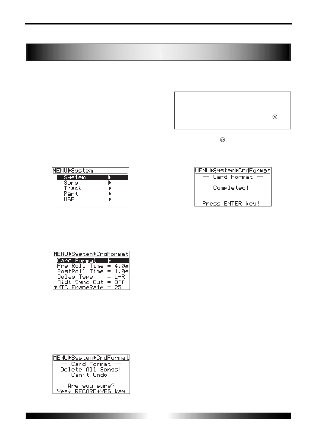
4) Press the [MENU] key to enter the menu mode.
The display changes to the menu selection
screen, in which "System" is initially
highlighted.
5) While "System" is highlighted, press the [ENTER]
key .
The display now shows the System menu
selection screen, in which "Card Format" is
initially highlighted.
6) While "Card Format" is highlighted, press the
[ENTER] key .
The display now shows the screen for
confirmation before the card format.
In this screen, "Delete All Songs!" and "Can't
Undo!" are shown for warning, as well as
"Y es-> RECORD+YES key " and "No-> NO key "
alternately flash.
<Note>
Once you start formatting, you cannot stop it on
the way.
To cancel formatting, press the [CURSOR ] key
when the confirmation screen is shown.
7) Press the [CURSOR ] key while holding down the
[RECORD] key .
The MR-8 starts formatting. When completed,
"Completed!" is shown on the display.
8) Press the [ENTER] key .
The screen exits the "Card Format" menu, and
automatically change to the "Select Song"
menu for creating a new song (01).
Then, select the song mode and enter the song
name to create a new song to the formatted
card, following the same procedure as
described on page 21.
26
MR-8 Owner’s Manual
BALANCE
UNBAL
BALANCE
UNBAL
MIN
MAX
2
1
R
L
PHONES
ST OUT
INPUT A
INPUT B
DRIVETRIM TRIM
GUITAR
GUITAR
PEAK
LINE MIC
PEAK
LINE MIC
MIN MAX
DIGITAL MULTITRACKER
Master recorder
or
Monitor Speaker
DC IN
POWER
USB
FOOT SW
DIGITAL
OUT
INPUT A SELECT
GUITAR
INT MIC
MIC/LINE
LIGHT
12V
ON
OFF
MIDI device
Personal Computer
AC main outlet
Foot switch
(Model 8051)
Digital master recorder
Headphones
Microphone
Guitar, ke yboard etc.
MIDI cable
USB cable
Optical cable
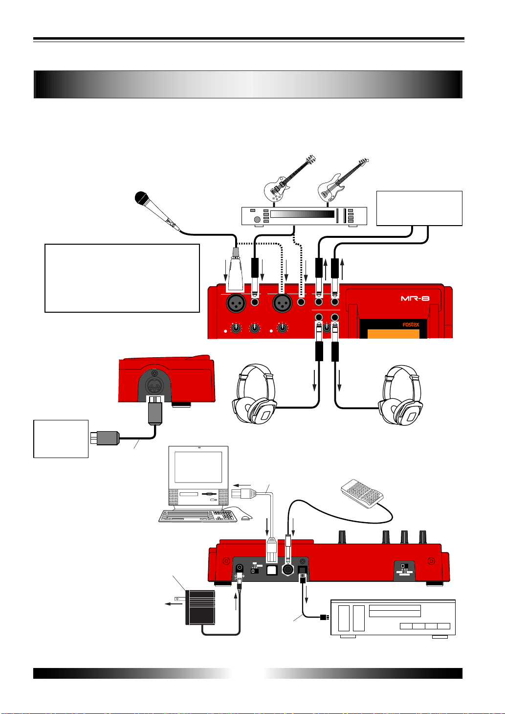
Connections
You can connect sound sources, recorders, a monitor amplifier, headphones, a personal computer, etc.
to the MR-8, as show in the figure below. When making connection or disconnection, make sure that
the [MASTER] fader and [PHONES VOL] control are turned down. Otherwise, the noise generated when
making connection or disconnection may damage external equipment.
<Note>
On each input section, the [UNBAL]
phone connector takes priority to the
[BAL] XLR connector. You cannot use
both the [UNBAL] and [BAL] connectors
on the same section simultaneously.
Model AD-12A
27
MR-8 Owner’s Manual
1
2
3
4
6
5
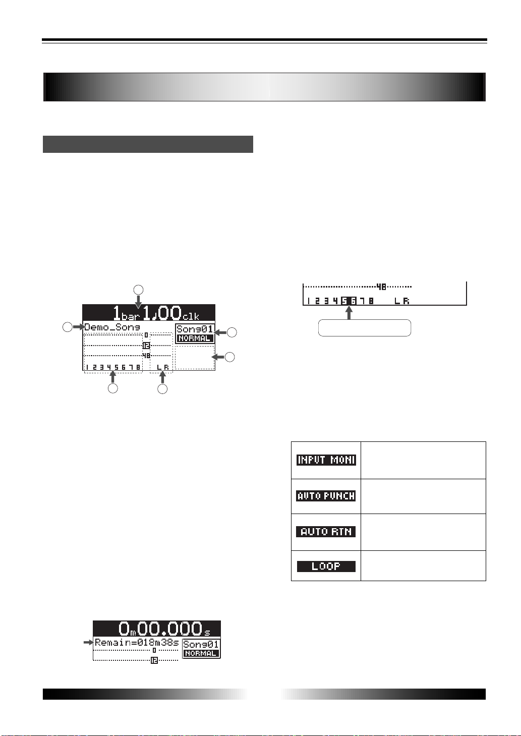
Display
The following describes details about the LCD display, including screen contents and opera-
tion.
Home screen
When turning on the MR-8 while a formatted
CompactFlash card is set, the display shows the
startup screen (showing the startup status of the
MR-8), followed by the "home" screen, which is
similar to the one below. In this condition, the
previously loaded song (or the demo song when
you first use the MR-8 with the supplied card) is
loaded and the recorder is located at the begin-
ning of the song.
The home screen includes the following infor-
mation.
1. Time counter display
Time information of the current recorder posi-
tion is shown in the selected time base (ABS, Bar/
Beat or time counter). Using the [TIME BASE SE-
LECT] key, you can select a desired time base.
When the recorder is moving (playing back, fast
forwarding, etc.), the appropriate icon is also
shown.
2. Character display
Normally, the name of the song currently loaded
is shown (up to 14 characters can be shown at a
time). It also shows following information.
• a name of the operation currently being
executed (such as “BOUNCE 1-6>7/8”).
• a warning message (such as "Low Battery!")
as a flashing display.
• The "Remain" time when at least one track
is armed (i.e. at least one of the
[REC SELECT] keys is active). The remain
time shows how much time you can
further record audio data onto a mono track
using the available space left on the
current card.
3. Trac k le vel display
The recording or playback levels of tracks 1
through 8 are shown. The track number of an
armed track is shown in reverse.
Tracks 5 and 6 are armed.
4. Stereo buss (L and R) le vel displa y
During recording or playback, the output levels
of the stereo buss (L and R) are shown.
5. Song status display
Shows the following song status icons when the
appropriate modes (functions) are active.
At least one of the tracks is in the
input monitor mode (see page 32).
The auto punch mode is active (see
page 36).
The auto return mode is active (see
page 50).
The loop mode is active (see page
50).
6. Song number/song mode displa y
Shows the song number and mode (Normal or
Extended) of the song currently loaded.
28
MR-8 Owner’s Manual
Example of time
counter display
Example of
Bar/Beat display
Low contrast
High contrast
Example of
ABS display
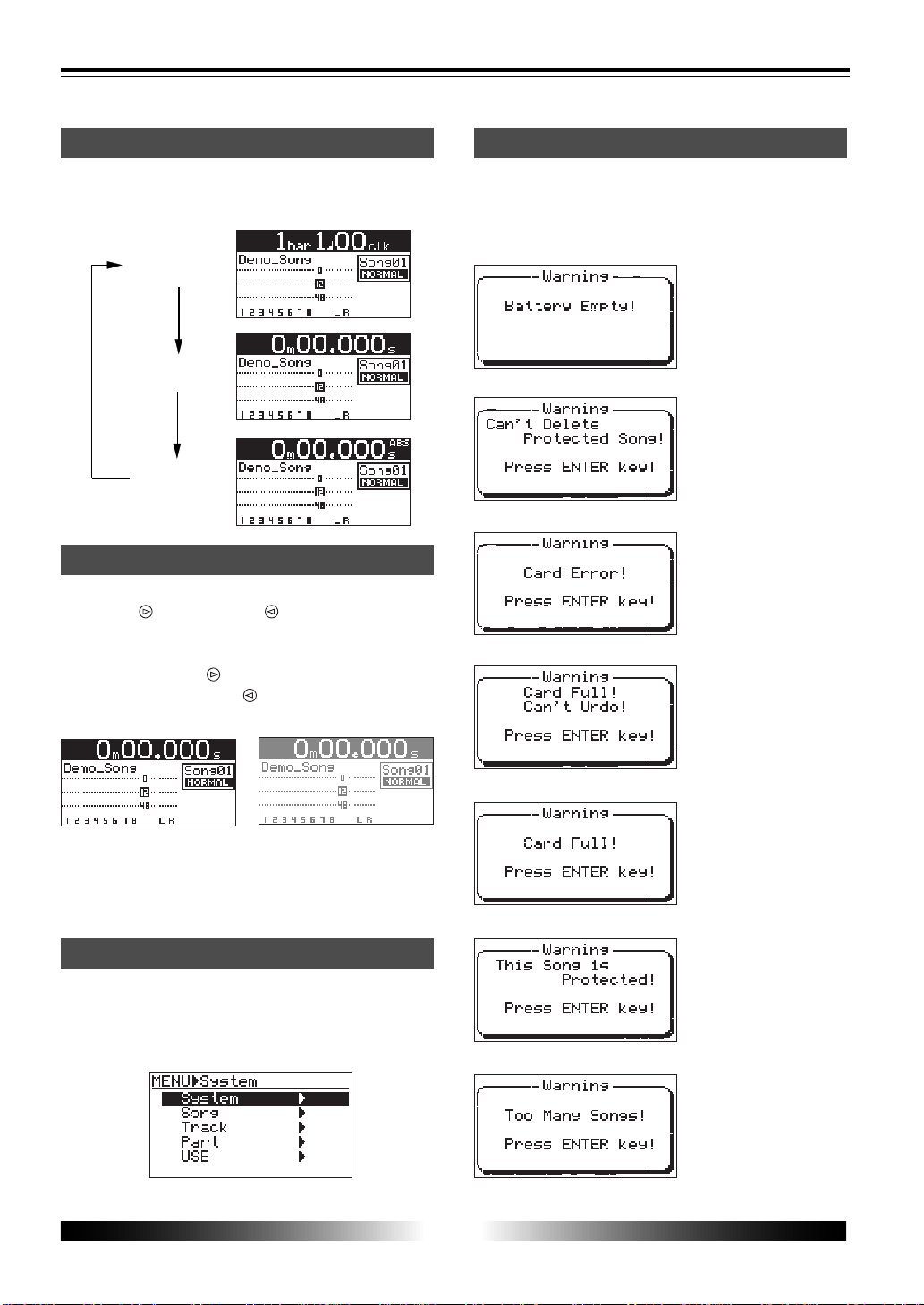
Selecting a time base
When the display shows the home screen, press-
ing the [TIME BASE SELECT] key switches the time
base among ABS, Bar/Beat and time counter.
Adjusting the display contrast
You can adjust the display contrast by using the
[CURSOR
] or [CURSOR ] key while holding
down the [MENU] and [ENTER] key simulta-
neously.
Use the [CURSOR
] key to heighten the con-
trast. Use the [CURSOR
] to lower the contrast.
You can reset to the default contrast setting by
pressing the [TIME BASE SELECT] key while hold-
ing down the [MENU] and [ENTER] key simulta-
neously.
MENU screen
Pressing the [MENU] key while the recorder is
stopped enters the menu mode and brings up
the MENU screen. In the menu mode, you can
make setting or editing via the appropriate MENU
screen.
Warning message
If a serious problem happens to the MR-8 during
operation, an appropriate warning message is
shown on the display. Most warning messages
are being shown until the [ENTER] key is pressed.
This message is shown
when the battery power is
too low to drive the unit.
This message is shown
when you are going to de-
lete a song which is pro-
tected.
This message is shown
when the MR-8 cannot read
a card.
This message is shown
when you are going to edit a
track or part the operation but
there is not enough space on
the card for executing the
undo function.
During recording, this mes-
sage is shown if there is no
more space on the card for
continuing recording.
This message is shown
when you are going to
record a material onto a
song or edit the song which
is protected.
This message is shown
when you are going to cre-
ate a new song while 99
songs exist on the card.
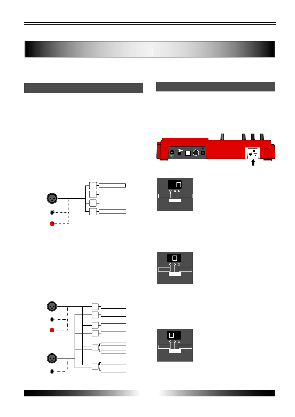
29
MR-8 Owner’s Manual
INPUT A
BALANCE
UNBALANCE
MIC
1
2
3
4
TRACK 1
TRACK 2
TRACK 3
TRACK 4
REC SEL
INPUT A
BALANCE
UNBALANCE
MIC
1
2
3
4
TRACK 1
TRACK 2
TRACK 3
TRACK 4
INPUT B
BALANCE
UNBALANCE
5/6
TRACK 5
TRACK 6
7/8
TRACK 7
TRACK 8
REC SEL
DC IN
POWER
USB
FOOT SW
DIGITAL
OUT
INPUT A SELECT
GUITAR
INT MIC
MIC/LINE
LIGHT
12V
ON
OFF
[INPUT A SELECT] switch
INPUT A SELECT
MIC/LINE
INT MIC
GUITAR
INPUT A SELECT
MIC/LINE
INT MIC
GUITAR
INPUT A SELECT
MIC/LINE
INT MIC
GUITAR
MR-8 recording basics
Before starting recording, we recommend to understand the MR-8 recording basics (such as
the relation between the input jacks and tracks and useful recording functions) described
below.
Relation between the input jacks and tracks
The MR-8 provides eight tracks (1 through 8)
and you can record onto a selected mono track
or stereo tracks at a time.
Depending on whether you select a mono track
or stereo tracks for recording, use the input jacks
appropriately as described below.
• Recording onto a mono track
Select a recording track by pressing any one of the
[REC SELECT] keys. When selecting a mono recording
track, only the [INPUT A] section can be used. Note
that you cannot use the [INPUT B] section.
• Recording onto stereo track
Select a pair of recording tracks (1 and 2, 3 and 4, 5/6,
or 7/8) by pressing the appropriate [REC SELECT]
key(s). Note that you can select tracks 5/6 or 7/8 by
pressing a single key, while you have to select tracks
"1 and 2" or "3 and 4" by pressing appropriate two
keys. When selecting stereo recording tracks, both the
[INPUT A] and [INPUT B] sections can be used. The
signals from the [INPUT A] and [INPUT B] sections are
recorded onto the odd and even tracks, respectively.
[INPUT A SELECT] switch
An internal microphone is built in the [INPUT A]
section. You can select a sound source of the [IN-
PUT A] section between this built-in microphone
or an external source (a guitar or mic/line source)
using the [INPUT A SELECT] switch.
MIC/LINE:
Set the switch to this position when
connecting an external microphone
or line-level source such as a key-
board. Both the [BAL] XLR and
[UNBAL/GUITAR] phone connectors
can be used. Use the [TRIM] control
to adjust the input level. When set-
ting the switch to the MIC/LINE po-
sition, the microphone simulation ef-
fect can be inserted.
GUIT AR:
Set the switch to this position when
connecting a guitar. Both the [BAL]
XLR and [UNBAL/GUITAR] phone
connectors can be used. Use the
[TRIM] control to adjust the input
level and use the [DISTORTION] con-
trol to control the distortion applied
to the source. When setting the
switch to the GUITAR position, the
guitar amplifier simulation effect can
be inserted.
INT MIC:
Set the switch to this position when
using the built-in microphone. Use
the [TRIM] control to adjust the in-
put level. When setting the switch
to this position, you cannot use the
[INPUT A] input connectors, as well
as the insert effect.
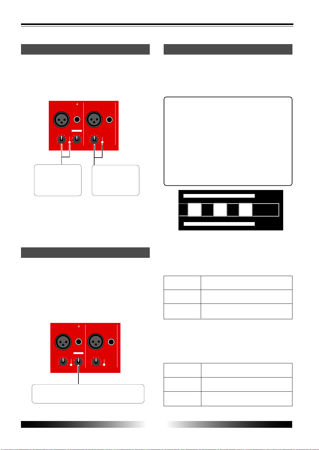
30
MR-8 Owner’s Manual
DYNAMIC
CONDENSER
TUBE
BRIT STACK
US MET AL
60s COMBO
INPUT A
BRIT STACK
US METAL
60's COMBO
DYNAMIC
CONDENSER
TUBE
MIC SIMULATION
AMP SIMULATION
BAL
UNBAL
/GUITAR
BAL
UNBAL
INPUT A
INPUT B
DISTORTIONTRIM
TRIM
PEAK
LINE MIC
PEAK
LINE MIC
MIN MAX
GUITAR
INPUT A SELECT
BAL
UNBAL
/GUITAR
BAL
UNBAL
INPUT A
INPUT B
DISTORTIONTRIM
TRIM
PEAK
LINE MIC
PEAK
LINE MIC
MIN MAX
GUITAR
INPUT A SELECT
Input level setting
Each of the [INPUT A] and [INPUT B] sections
provides the [TRIM] control, with which you can
adjust the input gain for any selected input
source. This adjustment determines the record-
ing level.
The [TRIM] control
and [PEAK] indicator
for the [INPUT A] sec-
tion.
The [TRIM] control
and [PEAK] indicator
for the [INPUT B]
section.
Set the [TRIM] control appropriately so that the
[PEAK] indicator does not light up at the loudest
part.
Distortion setting
You can apply distortion when recording an elec-
tric guitar.
To record a guitar with distortion, set the [INPUT
A SELECT] switch to "GUITAR" and connect a
guitar to the [UNBAL/GUITAR] phone connector
of [INPUT A].
The distortion level can be adjusted using the
[DISTORTION] control.
[DISTORTION] control which adjusts the distortion
level.
Insert effects
The [INPUT A] section provides the insert effects
which allows you to use a simulation effect when
recording the INPUT A signal. Depending on the
[INPUT A SELECT] switch setting, a microphone
or amplifier simulation effect can be used.
About simulation effect
The microphone and amplifier simulation
effects on the MR-8 simulate some of popular
microphones and guitar amplifiers. Each
simulation effect can produce the similar sonic
performance that it would have with the ac-
tual modeled microphone or guitar amplifier.
For example, selecting "TUBE" mic simulation
effect allows you to record a vocal sound from
your microphone as if you are using a tube
microphone.
Mic simulation effects
When the [INPUT A SELECT] switch is set to "MIC/
LINE", you can apply any one of the following
mic simulation effects by using the keys shown
in the illustration above.
Simulates the sound of a popular dynamic
microphone.
Simulates the sound of a popular condenser
microphone.
Simulates the sound of a popular tube mi-
crophone.
Amp. simulation eff ects
When the [INPUT A SELECT] switch is set to "GUI-
TAR", you can apply any one of the following
mic simulation effects by using the keys shown
in the illustration above.
Simulates a popular British stuck-type gui-
tar amplifier.
Simulates a popular US metal guitar ampli-
fier.
Simulates a popular tube combo guitar am-
plifier.
 Loading...