

Page 1

LOCATION RECORDER
Model PD204
OFF
AUX
C2
C1
MS
POWER
ON
MONITOR
PHONES
CIRCLE TAKECUE
SLATEJAM
FALSE START
TONE
OFF
MIC
RECPAUSE
3
JKL5MNO
6
TUV
LOCATE
CLEAR
symbol
WXYZ
09
PRE REC
FILE
CUE
NEXTPREV
ON
OFF
ENTER
ACCESS
BATT
YES
MENU
DVDHDD
DRV,PAT
LIGHT EXITFILE SELTIME
CONTRAST
QUICK SET
SHIFT
ST
MONO
L/M
R/S
MAXMIN
TC SET
PD204 LOCATION RECORDER
space1ABC2DEF
GHI
4
PQRS
8
7
Owner’s Manual
Page 2

Safety Instructions/Table of contents
CAUTION
RISK OF ELECTRIC SHOCK
DO NOT OPEN
CAUTION: TO REDUCE THE RISK OF ELECTRIC SHOCK,
DO NOT REMOVE COVER (OR BACK).
NO USER - SERVICEABLE PARTS INSIDE.
REFER SERVICING TO QUALIFIED SERVICE PERSONNEL.
"WARNING"
"TO REDUCE THE RISK OF FIRE OR ELECTRIC SHOCK,
DO NOT EXPOSE THIS APPLIANCE TO RAIN OR
MOISTURE."
SAFETY INSTRUCTIONS
1. Read Instructions - All the safety and operating instructions
should be read before the appliance is operated.
2. Retain Instructions - The safety and operating instructions
should be retained for future reference.
3. Heed Warnings - All warnings on the appliance and in the
operating instructions should be adhered to.
4. Follow Instructions - All operating and use instructions should
be followed.
5. Water and Moisture - The appliance should not be used near
water - for example, near a bathtub, washbowl, kitchen sink,
laundry tub, in a wet basement, or near a swimming pool, and
the like.
6. Carts and Stands - The appliance should be used only with a
cart or stand that is recommended by the manufacturer.
An appliance and cart combination should be moved with care.
Quick stops, excessive force, and uneven surfaces may cause
the appliance and cart combination to overturn.
7. Wall or Ceiling Mounting - The appliance should be mounted
to a wall or ceiling only as recommended by the manufacturer.
8. Ventilation - The appliance should be situated so that its location
or position dose not interfere with its proper ventilation.
For example, the appliance should not be situated on a bed,
sofa, rug, or similar surface that may block the ventilation
openings; or, placed in a built-in installation, such as a bookcase
or cabinet that may impede the flow of air through the ventilation
openings.
9. Heat - The appliance should be situated away from heat
sources such as radiators, heat registers, stoves, or other
appliances (including amplifiers) that produce heat.
10. Power Sources - The appliance should be connected to a power
supply only of the type described in the operating instructions
or as marked on the appliance.
11. Grounding or Polarization - The precautions that should be
taken so that the grounding or polarization means of an
appliance is not defeated.
CAUTION:
TO PREVENT ELECTRIC SHOCK, MATCH WIDE
BLADE OF PLUG TO WIDE SLOT, FULLY INSERT.
ATTENTION:
POUR EVITER LES CHOCS ELECTRIQUES,
INTRODUIRE LA LAME LA PLUS LARGE DE LA
FICHE DANS LA BORNE CORRESPONDANTE DE
LA PRISE ET POUSSER JUSQU' AU FOND.
The lightning flash with arrowhead symbol, within an
equilateral triangle, is intended to alert the user to
the presence of uninsulated "dangerous voltage"
within the product's enclosure that may be of sufficient
magnitude to constitute a risk of electric shock to
persons.
The exclamation point within an equilateral triangle
is intended to alert the user to the presence of
important operating and maintenance (servicing)
instructions in the literature accompanying the
appliance.
12. Power Cord Protection - Power supply cords should be routed
so that they are not likely to be walked on or pinched by items
placed upon or against them, paying particular attention to
cords at plugs, convenience receptacles, and the point where
they exit from the appliance.
13. Cleaning - The appliance should be cleaned only with dry cloth.
14. Nonuse Periods - The power cord of the appliance should be
unplugged from the outlet when left unused for a long period
of time.
15. Object and Liquid Entry - Care should be taken so that objects
do not fall and liquids are not spilled into the enclosure through
openings.
16. Damage Requiring Service - The appliance should be serviced
by qualified service personnel when:
A. The power supply cord or the plug has been damaged; or
B. Objects have fallen, or liquid has been spilled into the
appliance; or
C. The appliance has been exposed to rain; or
D. The appliance does not appear to operate normally or
exhibits a marked change in performance; or
E. The appliance has been dropped, or the enclosure damaged.
17. Servicing - The user should not attempt to service the appliance
beyond that described in the operating instructions.
All other servicing should be referred to qualified service
personnel.
18. The appliance should be situated away from drops of water or
spray of water.
19. Objects containing liquid such as vase must not be put on the
appliance.
20. The appliance is not completely isolated from the power supply
even if the power switch is at off position.
21. Appliance shall not be exposed to dripping or splashing and
no objects filled with liquids, such as vases, shall be placed on
the appliance.
22. Only use attachments/accessories specified by the
manufacturer.
23. An appliance with a protective earth terminal should be
connected to a mains outlet with a protective earth connection.
24. An appliance should be placed in a position where an AC plug/
inlet can be easily pulled out by hand.
25. Main plug is used as the disconnection device. It shall remain
readily operable and should not be obstructed during intended
use. To be completely disconnected the apparatus from supply
mains, the mains plug of the apparatus shall be disconnected
from the mains socket outlet completely.
2
Location Recorder Model PD204
Page 3

Safety Instructions/Table of contents
Important Safety Instructions
1) Read these instructions.
2) Keep these instructions.
3) Heed all warnings.
4) Follow all instructions.
5) Do not use this apparatus near water.
6) Clean only with dry cloth.
7) Do not block any ventilation openings.
Install in accordance with the
manufacturer's instructions.
8) Do not install near any heat sources such
as radiators, heat registers, stoves, or
other apparatus (including amplifiers) that
produce heat.
9) Do not defeat the safety purpose of the
polarized or grounding-type plug.
A polarized plug has two blades with one
wider than the other. A grounding type
plug has two blades and a third grounding
prong. The wide blade or the third prong
are provided for your safety.
If the provided plug does not fit into your
outlet, consult an electrician for
replacement of the obsolete outlet.
11) Only use attachments/accessories
specified by the manufacturer.
12) Use only with the cart, stand, tripod,
bracket, or table specified by the
manufacturer, or sold with the apparatus.
When a cart is used, use caution when
moving the cart/apparatus combination
to avoid injury from tip-over.
13) Unplug this apparatus during lightning
storms or when unused for long periods
of time.
14) Refer all servicing to qualified service
personnel. Servicing is required when the
apparatus has been damaged in any
way, such as power-supply cord or plug
is damaged, liquid has been spilled or
objects have fallen into the apparatus, the
apparatus has been exposed to rain or
moisture, does not operate normally, or
has been dropped.
10) Protect the power cord from being walked
on or pinched particularly at plugs,
convenience receptacles, and the point
where they exit from the apparatus.
Location Recorder Model PD204
3
Page 4

Safety Instructions/Table of contents
Table of contents
Introduction of this manual ................................................................................................................1 1
Precautions ..........................................................................................................................................1 1
Cautions for use ..................................................................................................................................13
Precautions of installation .................................................................................................................13
Chapter-1: Main features .....................................................................................15
Main features and functions .........................................................................................................16
What is in the box? .........................................................................................................................19
PD204 options and related Fostex products .............................................................................19
Chapter-2: Preparation before using the PD204 ..............................................21
Preparation of power supply ........................................................................................................22
Mounting the battery .....................................................................................................................23
Important settings for using the battery .....................................................................................24
Battery priority setting (essential when using more than one battery) ....................................24
Low battery warning setting ............................................................................................................24
Power supply priority setting (essential when using both [DC-IN] and a battery) ..................25
Protector adjustment ........................................................................................................................25
Saving the battery power ...............................................................................................................26
Battery condition display ..............................................................................................................26
Dismounting the battery ...............................................................................................................27
Using [DC-IN] (Connecting the AC adaptor) ...............................................................................28
Important settings for using [DC-IN] ...........................................................................................28
Low battery warning setting ............................................................................................................28
Power supply priority setting (essential when using both [DC-IN] and a battery) ..................28
Turning on the power ....................................................................................................................29
Display backlight and contrast .....................................................................................................30
Turning on the display backlight .............................................................................................. ......30
Adjusting the display contrast ........................................................................................................30
Turning off the power ....................................................................................................................30
Internal clock setting ...........................................................................................................................31
Preparation of a DVD-RAM disk ........................................................................................................33
Inserting a disk ................................................................................................................................33
Initial format of a DVD-RAM disk .................................................................................................34
Replacing the internal hard disk drive ..............................................................................................37
4
Location Recorder Model PD204
Page 5

Safety Instructions/Table of contents
Chapter-3: Names and functions .......................................................................39
Left side panel (inputs/outputs) ........................................................................................................40
Right side panel (inputs/outputs) ............................................................................................. .........42
Front panel ...........................................................................................................................................44
T op panel ..............................................................................................................................................52
Rear panel .................................................................................................................... .........................54
LCD display details .............................................................................................................................55
Home screen ....................................................................................................................................55
Time display .......................................................................................................................................55
Status information ....................................................................................................................56
File name/Next file name .........................................................................................................57
Disk remaining ..........................................................................................................................57
Current drive/file number ......................................................................................................57
Protect icon ........................................................................................................................................57
Screen examples ........................................................................................................................58
MENU list screen ..........................................................................................................................58
SYS SETUP menu screen ..............................................................................................................58
BATTERY SETUP menu screen ...................................................................................................58
TC SETUP menu screen ...............................................................................................................58
DISK UTILITY menu screen ........................................................................................................58
USB to PC menu screen ...............................................................................................................58
EDIT EDL FILE menu screen .......................................................................................................59
Audio file select screen ...............................................................................................................59
Drive select screen ......................................................................................................................59
CUE LIST screen ...........................................................................................................................59
Contrast adjustment screen .....................................................................................................59
Chapter-4: Basic connections ............................................................................61
Input connection .................................................................................................................................62
Analog audio input connection ....................................................................................................62
Digital audio input connection .....................................................................................................63
Time code input connection .........................................................................................................63
Sync signal connection ...................................................................................................................63
External audio signal connection for monitoring ......................................................................63
Output connection ..............................................................................................................................64
Analog audio output connection ..................................................................................................65
Digital audio output connection ...................................................................................................65
Time code output connection .......................................................................................................65
Word clock output connection ....................................................................................................65
Other connections ..............................................................................................................................66
USB keyboard connection ..............................................................................................................66
PC connection ..................................................................................................................................68
External controller connection .....................................................................................................68
Power connection ............................................................................................................................69
Location Recorder Model PD204
5
Page 6

Safety Instructions/Table of contents
Connection examples .........................................................................................................................70
Connection example for recording (1) ........................................................................................70
Connection example for recording (2) ........................................................................................71
Chapter-5: Recording/playback .........................................................................73
Preparation before recording ............................................................................................................74
Setup for recording in quick setup mode ....................................................................................74
How to make settings in the quick setup mode .............................................................................74
Frame rate selection for LTC (or external time code) ...................................................................75
System clock reference selection ....................................................................................................75
Sampling frequency and bit length selection ................................................................................76
TC recording mode setting ..............................................................................................................76
Clock pull up/pull down setting .....................................................................................................76
Power source priority selection .......................................................................................................77
Setting in the MENU mode .............................................................................................................77
Default file name setting ..................................................................................................................77
Maximum file size setting .................................................................................................................77
Partition link setting .........................................................................................................................77
Error tone output setting .................................................................................................................78
Mixer settings ..................................................................................................................................78
Input signal selection ........................................................................................................................79
High-pass filter setting ......................................................................................................................79
Limiter setting ..................................................................................................................................79
Adjusting the input gain (for channels 1 through 4) ...........................................................80
Phase setting (for channels 1 through 4) .......................................................................................82
Controlling signals sent to the stereo bus ..............................................................................82
Monitoring recording signals ..................................................................................................83
Selecting the drive for recording ..................................................................................................84
Recording analog audio .....................................................................................................................85
Starting recording ...........................................................................................................................85
About overloading during recording .............................................................................................86
Canceling recording (False Start) .................................................................................................86
Recording in Pre rec mode .............................................................................................................87
Recording a slate tone/slate mic signal .......................................................................................88
Recording digital audio ......................................................................................................................89
Selecting the sampling frequency/bit length .............................................................................89
Selecting the system clock .............................................................................................................89
Recording time code ...........................................................................................................................90
Selecting the TC frame rate ...........................................................................................................90
Selecting the TC generator mode (TC recording mode) ...........................................................90
Automatic record start by external time code ............................................................................91
Setting the time code output .........................................................................................................91
Force jam to external time code ........................................................................................................92
6
Location Recorder Model PD204
Page 7

Safety Instructions/Table of contents
Cue point setting .................................................................................................................................93
Setting a cue point on the fly during audio recording ..............................................................93
Viewing the cue point list ...............................................................................................................93
Editing a cue point ..........................................................................................................................94
Editing a cue label .............................................................................................................................94
Editing cue point data .......................................................................................................................94
Deleting a cue point ..........................................................................................................................95
Adding a new cue point to the cue point list ...............................................................................95
Basic playback ....................................................................................................................................96
Normal audio playback ..................................................................................................................96
Cueing playback ..............................................................................................................................97
Time code playback ........................................................................................................................97
Skip/locate functions ........................................................................................................................98
Skipping by file .............................................................................................................................98
Skipping by cue point .................................................................................................................98
Locating to the beginning (ABS 0) of a file ................................................................................99
Locating to the end (REC END) of a file ......................................................................................99
Locating to the previous locate point ........................................................................................99
Locating to the desired time ........................................................................................................100
Locating to the desired cue point ...............................................................................................101
Chapter-6: Advanced operations .....................................................................103
Auto copy function ............................................................................................................................104
Setting a partition .........................................................................................................................104
Selecting auto copy mode ............................................................................................................105
Making auto copy .........................................................................................................................106
Disk copy function ............................................................................................................................107
Selecting source drive ..................................................................................................................107
Making disk copy ..........................................................................................................................108
File copy function ..............................................................................................................................1 10
Selecting source drive ..................................................................................................................110
Making file copy ............................................................................................................................111
Dual drive recording .........................................................................................................................1 13
Formatting in the “DDR” mode ..................................................................................................113
Making dual drive recording ......................................................................................................115
Data export to PC ...............................................................................................................................116
Connecting PC to the unit ............................................................................................................117
Location Recorder Model PD204
7
Page 8

Safety Instructions/Table of contents
How to unmount the PD204 from the PC ..................................................................................117
Example of copying data to a computer hard disk ..................................................................118
Example of exporting data to a computer application ............................................................118
Chapter-7: Creating and editing ALE files (EDIT EDL FILE menu) ..............121
Creating a new ALE file .....................................................................................................................122
Adding audio file entries to an ALE file ..........................................................................................125
Viewing and editing audio file entries .............................................................................................127
Viewing audio file entries ............................................................................................................127
Adding an audio file entry to an existing ALE file ....................................................................128
Deleting an audio file entry .........................................................................................................128
Editing an ALE file .............................................................................................................................129
Editing an ALE file name ..............................................................................................................129
Remarking an ALE file ..................................................................................................................130
Deleting an ALE file .......................................................................................................................131
Chapter-8: MENU mode .....................................................................................133
About MENU mode ...........................................................................................................................134
SYS SETUP menu ............................................................................................................... ..............136
Project name setting [Set project name] ....................................................................................137
Default file name setting [Default file name] ............................................................................138
Default track name setting [Default TrkName] ........................................................................140
Next event number setting [Next event No] ..............................................................................141
Recording FS/bit length setting [Record FS&Bit] .....................................................................142
Pull up/down setting [Pull up/down] ........................................................................................143
Digital output signal format selection [Digital out] .................................................................144
Diagnoses file setting [Diagnoses] ..............................................................................................145
Peak hold time setting [Peak hold] .............................................................................................146
Slate tone/pop tone recording mode setting [Tone rec mode] .............................................147
Pause cancel time setting [Pause time] ......................................................................................149
USB keyboard type setting [Keyboard] .....................................................................................150
Pre recording time setting [Pre rec time] ..................................................................................151
Maximum file length setting [Max file length] .........................................................................152
Continuous recording function [Auto part. link] ....................................................................153
False start mode setting [False start] ..........................................................................................155
Limiter parameter setting [Limiter parameter] .......................................................................156
8
Location Recorder Model PD204
Page 9

Safety Instructions/Table of contents
ANALOG OUT nominal level setting [Stereo out level] ...........................................................158
Monitor speaker mute setting [Speaker mute] .........................................................................159
Error tone output setting [Error tone] .......................................................................................160
Chain play mode setting [Chain play] .......................................................................................163
ROM version checking [Version] ................................................................................................164
BA TTERY SETUP menu ...................................................................................................................165
Battery low voltage warning setting [BATT. warning] .............................................................166
DC-IN low voltage warning setting [DC-IN warning] ...............................................................167
Power supply priority setting [Power priority] ........................................................................168
Battery priority setting [Active battery] ....................................................................................169
Battery setting examples .............................................................................................................170
Battery remaining time [BATT. Remain] ...................................................................................172
Battery status [BATT. status] .......................................................................................................173
TC SETUP menu ...............................................................................................................................174
System clock selection [Sync clock] ...........................................................................................175
TC frame rate selection [Frame rate] .........................................................................................176
Generator mode selection [Gen mode] .....................................................................................177
Internal TC generator setting [Set Gen. TC] ..............................................................................178
User bit setting [Set Gen Ubit] .....................................................................................................180
Jam mode setting [JAM mode] ....................................................................................................182
Time code output source selection [Sel. TC Out] .....................................................................183
Default LTC start time setting [Default LTC start] ....................................................................184
LTC start time editing [Edit LTC start] .......................................................................................185
UBIT setting of playback time code [Ref TC Ubit] ....................................................................186
Time code output while paused [Rep pause TC] ......................................................................187
Automatic recording start by external TC [Recin via ExtTC] ..................................................188
Internal TC generator power-off timer setting [TC PWR Timer] ..........................................189
DISK UTILITY menu ..........................................................................................................................190
Editing a file name [Edit file name] ............................................................................................191
Viewing a file information and editing descriptor information [File info.] .........................192
Editing descriptor information .....................................................................................................194
Adding descriptor information ....................................................................................................194
Deleting descriptor information ...................................................................................................194
Viewing iXML Chunk data information .......................................................................................195
Editing iXML Chunk data information .........................................................................................195
Deleting an unnecessary audio file [Delete file] .................................................................196
Restoring a deleted audio file [Restore Del. file] .................................................................197
Formatting a disk (or a hard disk partition) [Format] .......................................................198
Editing the reel number (Volume label) [Reel No.] ............................................................202
Record protection On/Off setting [Rec protect] ...............................................................203
Location Recorder Model PD204
9
Page 10

Safety Instructions/Table of contents
Resume function On/Off setting [Resume] .........................................................................204
Partition protection On/Off setting [Part. protect] ............................................................205
HDD operating time display [HDD Ope. Time] ...................................................................206
LOAD SETUP menu ....................................................................................................................207
SA VE SETUP menu .....................................................................................................................208
Chapter-9: Specifications .............................................................................209
Inputs/outputs ..............................................................................................................................210
Recording/playback ....................................................................................................................211
General ..........................................................................................................................................21 1
Physical dimensions ...................................................................................................................212
Block diagram ..............................................................................................................................213
INDEX ............................................................................................................................................214
10
Location Recorder Model PD204
Page 11

Introduction of this manual
This manual is a guidebook for using the Fostex PD204 Location Recorder.
This manual is intended for users who have experience and knowledge of
using a professional digital recorder.
You may roughly understand how to use the PD204 by reading "Chapter
1: Main features" and "Chapter 3: Names and functions".
"Chapter 3: Names and functions" describes names and functions of keys,
controls and connectors, as well as reference pages. So you can refer to
this chapter as index for detail information.
"Chapter 2: Preparations before using the PD204" contains the necessary
information when using the PD204 for the first time, such as "About power
supply" and "Initial format of a DVD-RAM disk".
Precautions
• For supplying the power to the unit from an AC outlet, only use the
Fostex authorized AC adaptor (optional).
If you use any unauthorized AC adaptor, the unit may not work
correctly and there is a serious risk of damage to the unit.
Introduction
• Make sure that the voltage of your AC power outlet matches the
voltage requirements printed on the AC adaptor.
If you wish to use the unit in a country where the voltage of the AC
power outlet does not match your AC adaptor, ask your local Fostex
dealer or service station for purchasing an appropriate AC adaptor.
Note that the AC adaptor can be used both in 50 Hz and 60 Hz areas.
• Never supply voltage other than DC12V to the unit.
• Only use the IDX ENDURA or NP-1 type battery (if you use the NP-1
type battery, the dedicated holder and holder plate are needed).
* IDX, IDX (logo), ENDURE, V-Mount, V-Plate, Digi-View and i-Trax are the trademarks of IDX
Company Ltd..
• When inserting/replacing batteries or disconnecting the AC
adaptor, make sure that the unit main power is off. Otherwise,
memory data may be damaged because the unit always handles data
while the power is on.
• While the unit is accessing to a disk, never turn off the power.
Make sure that the unit completely stops accessing to the disk
before you turn off the power. Otherwise, recorded data may be
lost, as well as the internal hard disk or DVD drive may be damaged.
<Note>:
due to use of the unit.
<Note>:
damage" caused by using the unit.
Fostex assumes no responsibility on data loss or whatsoever
Fostex is not responsible for any "direct damage" or "indirect
Location Recorder Model PD204
11
Page 12

Introduction
• Do not let water or other liquid, or metal objects such as pins,
accidentally enter the inside of the unit (especially inside of the disk
tray) because this may lead to electric shock or damage. Should
water enter the inside of the unit, turn off the power, unplug the AC
adaptor and remove batteries, and consult your dealer or the
nearest FOSTEX service station.
• Do not drop the unit or give it a strong shock. Doing so may damage
the internal circuits, display or panels. Handle the unit with great
care because it is a precision mechanical device.
• Do not open the case or touch inside the unit because of the danger
of electric shock and failure.
• Do not give a strong shock to the LCD display. The liquid used inside
the LCD display is toxic. If the liquid is spilled, do not suck it in.
If it is stained to your hand or skin, wash immediately with plenty of
water.
• Though the unit is designed to be used outside, it is not perfectly
waterproofed. So do not use the unit where it catches the rain or
spray directly.
<About replacing the lithium battery>
The unit contains the internal lithium battery for running the internal
clock. The battery should be replaced approximately every five years.
To replace the battery, ask your dealer or the nearest FOSTEX service
station. If the battery is not correctly replaced, there may be a risk of
explosion, etc.
<Important!>
The model name, power requirement and serial number for the PD204 are indicated on the bottom
side.
LOCATION RECORDER
FOSTEX CO.
INPUT: 12~24VDC
SERIAL NO.
MODEL PD204
MADE IN JAPAN
12
Location Recorder Model PD204
Page 13

Introduction
5.0(A )XAM
V42-21
NI-CD
V42-21
UO-CDT
DBYK
TSOH
CP
BSU
L IN OUTR
ADJUST
DIGITAL
ANALOG OUT
1:GND
1:GND
2:NC
3:NC
4:12-24V
1:GND
2:NC
3:NC
4:12-24V
2:HOT
3:COLD
XLR
DC-IN DC-OUT
Cautions for use
If you make recording or playback using a DVD-RAM disk, do not hang
the unit using the shoulder belt, which may damage the DVD drive.
Put the unit on a horizontal surface within the adjustable range of the
height adjustment arm.
* You can put the unit vertically when you make recording to the internal hard disk.
ADJUST
L IN OUTR
NI-CD
LOCATEABS 0
LOCATE REC END
ANALOG OUT
(dB/oct)
-12 -6 OFF
HPF
30050
30050
(Hz)
200130
200130
48V T12DM48V T12DM48V T12DM48V T12DM
INPUT SEL
MICLINEMICLINEMICLINEMICLINE
UO-CDT
V42-21
V42-21
5.0(A )XAM
BSU
TSOH
DBYK
CP
OPEN
OFF
LOCK
PANEL LOCK
REW F FWD PLAY STOP
-12 -6 OFF
-12 -6 OFF
-12 -6 OFF
30050
30050
200130
200130
DIGITAL
DC-IN DC-OUT
1:GND
2:NC
3:NC
4:12-24V
DISC IN
1:GND
2:NC
3:NC
4:12-24V
XLR
1:GND
2:HOT
3:COLD
Precautions on installation
• Do not install the unit in the following conditions
* In an extremely hot or cold place
* In a moist place
* In a vibrated place
* In a dusty place
* In a strong magnetic field or near a device which generates a
magnetic field
* In the direct sunshine
* In the direct shower or rain
• Notes on moisture condensation
When you bring the unit from a cold place to a warm place,
moisture may condense on the drive, display, panels, etc. In such a
case, leave the unit for a while until it warms up and evaporates any
moisture.
Location Recorder Model PD204
13
Page 14

Introduction
14
Location Recorder Model PD204
Page 15

Chapter 1: Main features
Chapter 1: Main features
Location Recorder Model PD204
15
Page 16

Chapter 1: Main features
• Equipped with four analog inputs and two analog outputs as well as twochannel digital input and output. You can record signals from these inputs in
stereo. Two Aux analog inputs are also provided for monitoring the audio
track of a camera via headphones. (Note that the Aux inputs are provided for
monitoring only and you cannot record the Aux input signals.)
Main features and functions
AUX input L, R
RL
AUX IN
ETOMER-P9
PELLARAL
Analog inputs 1-4
DROW
UOT
UAT ES OL
/DROW
OEDIV
NI
NI GOLANA
FFONO
1234
TSUJDA
EDOC EMIT
NITUO
Analog output L, R
L IN OUTR
ANALOG OUT
ADJUST
UO-CDT
V42-21
V42-21
NI-CD
5.0(A )XAM
BSU
TSOH
DBYK
CP
Digital input/output
DIGITAL
DC-IN DC-OUT
1:GND
1:GND
2:NC
2:NC
3:NC
3:NC
4:12-24V
4:12-24V
XLR
1:GND
2:HOT
3:COLD
• Equipped with a 1.8-inch hard disk drive (80GB) and a 12-cm DVD multi
drive as standard. You can directly make recording to the hard disk partition
or DVD-RAM disk. In addition, you also can make "Auto copy", "File Copy"
and "Disk Copy" between a DVD-RAM disk and a hard disk partition, as well
as "Dual Drive Recording".
The internal hard disk drive can be replaced with the optional hard disk
drive unit (Model EX-HD1) by a user. The DVD multi drive is the slot loading
type and can accept a 4.7GB, non-cartridge DVD-RAM, DVD-R or DVD-RW
disk (only a DVD-RAM disk can be used for direct recording).
1.8-inch hard disk drive
MICLINEMICLINEMICLINEMICLINE
INPUT SEL
48V T12DM48V T12DM48V T12DM48V T12DM
200130
200130
200130
200130
(Hz)
30050
30050
HPF
-12 -6 OFF
(dB/oct)
LOCATE REC END
LOCATEABS 0
12-cm DVD combo drive
30050
30050
-12 -6 OFF
-12 -6 OFF
-12 -6 OFF
PANEL LOCK
DISC IN
OPEN
REW F FWD PLAY STOP
LOCK
OFF
For the optional hard disk drive unit for replacement, ask your local Fostex
dealer or service station.
16
Location Recorder Model PD204
Page 17

Chapter 1: Main features
• The DVD-RAM disk format is conformed to "UDF Rev1.5", which ensures great
compatibility with personal computers.
• The recording file format is conformed to the versatile BWF format. You can
export a recorded file including time code information to a BWF-compatible
application.
• Can be used with the optional AC adaptor or IDX ENDURA battery (V-mount
type). You can stack up to four batteries for longer recording time.
• Built in the internal generator with the jam sync function. The unit is equipped
with the time code input/output connectors (XLR), so you can stripe not only
the internal time code but also an external time code.
AUX IN
PELLARAL
RL
ETOMER-P9
DROW
UOT
UAT ES OL
/DROW
OEDIV
NI
FFONO
1234
NI GOLANA
EDOC EMIT
NITUO
TSUJDA
TIME CODE IN/OUT connectors
• Provides the word sync function, allowing synchronization with external
digital equipment.
RL
AUX IN
ETOMER-P9
DROW
PELLARAL
UOT
UAT ES OL
/DROW
OEDIV
NI
FFONO
WORD/VIDEO IN and WORD OUT connectors
1234
NI GOLANA
EDOC EMIT
NITUO
TSUJDA
• Equipped with the [USB PC] port for PC connection. You can directly connect
to a PC, allowing to mount the internal hard disk and DVD drives to the PC.
The unit also provides the [USB HOST] port for future expansion.
In addition, the [USB KYBD] port is also provided for USB keyboard
connection, which allows you to enter file names and volume labels from a
USB keyboard.
ADJUST
L IN OUTR
ANALOG OUT
V42-21
NI-CD
UO-CDT
V42-21
5.0(A )XAM
BSU
TSOH
DBYK
CP
USB port
Location Recorder Model PD204
DIGITAL
DC-IN DC-OUT
1:GND
2:NC
3:NC
4:12-24V
1:GND
2:NC
3:NC
4:12-24V
1:GND
2:HOT
3:COLD
XLR
17
Page 18

Chapter 1: Main features
• You can export a recorded audio file to the AVID system by creating the ALE
file.
• The Mark/Cue function allows to store markers (cue points) during
recording. You can locate or skip to a cue point quickly.
• The "False start" function allows to cancel recording easily.
• "Pre Record" function allows glitch-free recording. When this function is
active, recent audio data is pooled in the buffer and recording starts from the
audio data in the buffer.
• During recording, the audio file is automatically saved every minute in
background.
• Equipped with the digital mixer which you can enjoy intuitive analog-like
operation.
Mixer section
• In 24-bit/48kHz mode, you can record up to approximately 256 minutes onto
two tracks.
* The times shown above are the recording times on a DVD-RAM disk (4.7GB)
or a partition (approx. 4.5GB) of the hard disk.
• In 24-bit mode, you can make recording with sampling frequencies of 44.1/
48 kHz, 88.2 kHz, 96 kHz, 176.4 kHz and 192 kHz.
In 16-bit mode, you can make recording with sampling frequencies of 44.1
kHz and 48 kHz.
18
Location Recorder Model PD204
Page 19

Chapter 1: Main features
What is in the box?
Make sure that the box contains the following. If any of them are missing, please
contact your dealer.
PD204
Shoulder belt
Operation manual (this manual)
Driver software (CD)
1
1
1
1
PD204 options and related Fostex products
The following PD204 options and related products are available.
Ask your local Fostex dealer or sale office for details about them such as prices,
specifications, etc.
You can also get product information from our web site below.
http://www .fostex.com
Options
• AC adaptor: Model AD15-4300 or AD-15C
• 1.8-inch hard disk drive: Model EX-HD1
• Battery plate: Model EX-BP1
• Soft case: Model ZP-62
Related products
• Location recorder: Model PD606
• DVD multitrack recorder: Model DV824
• Portable location recorder: Model FR-2LE
• Personal powered monitor: Model 6301B/BX/BE
• Stereo headphones: Model T20RPMkII/T-5/T-7/T40RPMkII/T50RP
Location Recorder Model PD204
19
Page 20

Chapter 1: Main features
20
Location Recorder Model PD204
Page 21

Chapter 2: Preparation before using the PD204
Chapter 2: Preparation before using the PD204
This chapter explains what you should do before using the PD204 for the first time, including
power connection, internal clock setting and preparation of the DVD-RAM disk.
It also explains how to replace the internal hard disk drive.
Chapter 2 - Table of contents
Preparation of power supply .....................................................................................................22
Mounting the battery .............................................................................................................23
Important settings for using the battery .............................................................................24
Battery priority setting (essential when using more than one battery) ......................24
Low battery warning setting ..............................................................................................24
Power supply priority setting (essential when using both [DC IN] and battery) ..25
Protector adjustment ..........................................................................................................25
Saving the battery power .......................................................................................................26
Battery condition display ......................................................................................................26
Dismounting the battery .......................................................................................................27
Using [DC IN] (Connecting the AC adaptor) .......................................................................28
Important settings for using [DC IN] ....................................................................................28
Low battery warning setting ..............................................................................................28
Power supply priority setting (essential when using both [DC IN] and battery) ..28
Turning on the power ............................................................................................................29
Display backlight and contrast .............................................................................................30
Turning on the display backlight ......................................................................................30
Adjusting the display contrast ..........................................................................................30
Turning off the power ............................................................................................................30
Internal clock setting ..................................................................................................................31
Preparation of a DVD-RAM disk ................................................................................................33
Inserting a disk ........................................................................................................................33
Initial format of a DVD-RAM disk .........................................................................................34
Replacing the internal hard disk drive .....................................................................................37
Location Recorder Model PD204
21
Page 22

Chapter 2: Preparation before using the PD204
Preparation of power supply
The unit can operate on the mobile IDX ENDURA or NP-1 type battery, as well as the dedicated
AC adaptor.
IDX ENDURA battery
NP-1 type battery
Holder and holder plate for the NP series
Dedicated AC adaptor (optional)
<Note>:
plate) and AC adaptor are not included with the unit. For the information about the
AC adaptor, ask your dealer or the nearest FOSTEX service station.
<Note>:
the battery, you must charge it according to the manual of the battery (note that the
PD204 does not provide the battery charge function). Also note that you must handle
the battery correctly according to the manual of the battery.
<Note>:
PD204 without any special parts, however, the holder projects from the PD204 body.
If you want to mount the NP-1 battery housed in the dedicated holder to the PD204
without projecting from the PD204 body, the optional mounting hardware (Model
EX-BP1) is needed. Ask your dealer or the local Fostex service station for installing
the mounting hardware. The mounting hardware must be installed by Fostex service
station.
The IDX ENDURA battery, NP-1 type battery (including the holder and holder
In general, a battery is not charged when shipped. Therefore, before using
You can mount the NP-1 battery housed in the dedicated holder to the
* IDX, IDX (logo), ENDURE, V-Mount, V-Plate, Digi-View and i-Trax are the trademarks of IDX Company Ltd..
22
Location Recorder Model PD204
Page 23

Chapter 2: Preparation before using the PD204
Mounting the battery
The ENDURA battery is mounted to the bottom of the PD204.
There are two mounts for mounting the batteries. If you use the non-PowerLink type
batteries, you can mount one battery for each base. If you use the PowerLink type
batteries, you can mount up to four batteries (two batteries for each base).
<Note>:
By sudden power failure, memory data may be reset or the unit may be damaged because the unit handles data while the power is on. However, note that, if you set two
batteries, you can replace a battery which is not currently active.
<Note>:
the battery and handle it correctly. The PD204 does not provide battery charge function. Charge the IDX ENDURA battery correctly according to the battery manual.
When you mount or replace the battery, make sure that the unit power is off.
If you use the IDX ENDURA battery, read the operation manual supplied with
Battery mount 2 (BATT2)
Battery mount 1 (BATT1)
Connectors
ENDURA battery
ENDURA battery
<Example of mounting the ENDURA batteries to the both battery mounts>
Location Recorder Model PD204
23
Page 24

Chapter 2: Preparation before using the PD204
When you use PowerLink batteries, you
can mount up to four batteries (two batteries for each base, as shown on the
right).
<Note>:
ies, you cannot use the protector on the
bottom panel. Use the unit horizontally.
When you mount four batter-
<Notes for using PowerLink batteries>
• When you use PowerLink batteries, use batteries of the same charging
condition. If the charging conditions are significantly different, the PowerLink
function may not operate correctly resulting the PD204 powered off.
• You cannot mount more than two batteries. Each battery mount can accept up
to two batteries.
Important settings for using the battery
Battery priority setting (essential when using more than one battery)
When you use two batteries or four PowerLink batteries, you must set the battery
priority (BATT1 or BATT2).
You can specify the battery to be used preferentially. When the preferential battery
gets empty, the display shows the warning popup window and the other battery automatically takes over.
You can make setting via the quick setup mode or via the "Active battery" item in the
"BATTERY SETUP" menu of the MENU mode (see pages
77 and 169).
Low battery warning setting
Whether you use a battery with or without BMS (Battery Management System), you
can set the threshold voltage for warning low battery.
When the battery voltage gets lower than the threshold voltage you set, the warning
tone is output from the headphones connected to the unit.
By default, the threshold voltage is set to 13.2V for battery with BMS or 13.0V for
battery without BMS. However, you can set the desired threshold voltage via the "BATT.
warning" item in the "BATTERY SETUP" menu of the MENU mode (see page
<Note>:
the battery information via the "BATT. status" item in the "BATTERY SETUP" menu of
the MENU mode (see page 173).
<Note>:
the remaining time until the battery voltage reaches the threshold voltage in one-minute
steps via the "BATT. Remain" item in the "BATTERY SETUP" menu of the MENU mode
(see page 172).
<Note>:
the remaining power gets short, the output voltage rapidly drops. Therefore, to replace
the battery well in advance, we recommend setting the threshold voltage to 13 V or
around.
When you use a battery with BMS (Battery Management System), you can check
When you use a battery with BMS (Battery Management System), you can check
While the battery has power, the output voltage is between 13 V to 15 V. When
166).
24
Location Recorder Model PD204
Page 25

Chapter 2: Preparation before using the PD204
TUO
TSUJDA
Power supply priority setting (essential when using both [DC IN] and a battery)
When you use both a battery and the [DC IN] connector, you must set the power
supply priority ("DC-IN" or "BATT"). For example, if you set it to "DC-IN", the battery
automatically takes over only when the power supply from the "DC-IN" jack is cut off
(power failure, disconnection, etc).
Note that, if you use only batteries, you do not need to make this setting.
You can make setting via the "Power priority" item in the "BATTERY SETUP" menu of
the MENU mode (see page
168).
Protector adjustment
When the battery is mounted, pull out the protector to protect the battery, as shown
below. While sliding the [ADJUST] levers on left and right side panels to the arrow
direction, pull out the protector. There are two locked positions for the protector.
Set it to the appropriate position. Note that you should push it down when replacing
the battery.
Protector
[ADJUST] levers
<Note>:
The protector can protect the IDX ENDURA-7 and ENDURA-7S. When you
use the ENDURA-10 or ENDURA-10S, or PowerLink is active, we recommend using
the PD204 horizontally.
Location Recorder Model PD204
25
Page 26

Chapter 2: Preparation before using the PD204
Saving the battery power
The PD204 offers the following measures for saving the battery power to extend the
battery life.
• Pressing the [STOP] key stops the disk rotation to save the power consumption.
It is also possible to set the desired pause release time using the "Pause time" item in
the SYS SETUP menu of the MENU mode (the default pause time is three minutes).
• When the internal monitor speaker is not used or when a headphone plug is inserted
to the [PHONES] jack, no power is supplied to the amplifier for the speaker.
The following describes some tips for saving the battery power, as well as some notes on
using the battery.
• When you do not operate the unit on battery power for a long period of time, remove
the battery. Even if the [POWER] switch is set to "OFF", a small amount of electric
power is consumed.
• Set the monitor level as lower as possible (regardless of whether using headphones
or the internal monitor speaker).
• You should use the display backlight only when needed.
• When you do not use a DVD-RAM disk, remove the disk.
• The load impedance connected to PD204 output connectors should be greater than
10k ohm.
• When converting a balanced output to an unbalanced output, you should not
connect the unused pin to the ground pin and leave it open. Though it lowers the
output level by 6dB, it does not influence to the audio characteristics.
You can check the current battery remaining amount in realtime by following the procedure described below.
Battery condition display
You can check the battery remaining amount in realtime from the [ST BUS] bargraph
meters beside the LCD display on the front panel.
By pressing and holding down the [EXIT/
the display shows the Home screen (in stop, playback or record mode), the [ST BUS]
bargraph meters show the battery remaining amount in % and the display pops up the
battery power voltage in V. Releasing the [EXIT/
stereo buss level monitoring and dismiss the popup window).
When you use a non-BMS battery, only the display pops up the battery power voltage.
EXIT
[EXIT / BA TT] key
BATT
ENTER
YES
OFF
AUX
C2
C1
MS
POWER
ON
MONITOR
PHONES
SHIFT
ST
MONO
L/M
R/S
MAXMIN
QUICK SET
PD204 LOCATION RECORDER
TC SET
DRV,PAT
LIGHT EXITFILE SELTIME
CONTRAST
ACCESS
BATT
MENU
DVDHDD
BATT] key when you use a BMS battery and
BATT] key returns the meters to the
[ST BUS] bar-graph meters
space1ABC2DEF
GHI
JKL5MNO
4
Shows the
BATT1
remaining
amount
LOCATE
3
6
WXYZ8TUV7PQRS
09
FILE
CUE
CLEAR
PRE REC
symbol
ON
OFF
CIRCLE TAKECUE
NEXTPREV
SLATEJAM
FALSE START
TONE
OFF
MIC
Shows the
BATT2
remaining
amount
RECPAUSE
26
Location Recorder Model PD204
Page 27

Chapter 2: Preparation before using the PD204
Dismounting the battery
To dismount the battery, make sure that the power is off, and remove the battery
while pressing the release button on the IDX ENDURA battery or press down the eject
lever on the PD204.
Eject lever on the PD204
Eject lever on the PD204
<Note>:
Keep the removed battery away from children.
Dispose the used battery properly (see the instruction manual of your battery).
Location Recorder Model PD204
Release button
27
Page 28

Chapter 2: Preparation before using the PD204
Using [DC-IN] (Connecting the AC adaptor)
You can connect the AC adaptor or another appropriate power source to the [DC IN]
connector on the left side panel of the PD204. If you use the AC adaptor, insert the
XLR-4-32 type connector of the AC adaptor to the [DC IN] connector until it is locked,
then connect the AC plug to the AC main outlet (see the figure below).
<Notes>
• When you connect or disconnect the connector, make sure that the power is off.
• Use only the Fostex dedicated AC adaptor. Using another AC adaptor may damage
the PD204 due to the mismatch of the power voltage, polarity, etc. When connect or
disconnect the AC adaptor, make sure that the [POWER] switch is set to "OFF".
The AC adaptor for the PD204 is optionally available (ask your local Fostex dealer or
sale office for purchasing the option).
ADJUST
L IN OUTR
ANALOG OUT
NI-CD
V42-21
UO-CDT
V42-21
5.0(A )XAM
BSU
TSOH
DBYK
CP
DIGITAL
DC-IN DC-OUT
1:GND
2:NC
3:NC
4:12-24V
1:GND
2:NC
3:NC
4:12-24V
1:GND
2:HOT
3:COLD
XLR
[DC IN] connector
AC adaptor
To the AC main outlet
Important settings for using [DC IN]
Low battery warning setting
When you get the power from the [DC IN] connector (such as use the AC adaptor), you
can set the threshold voltage for warning low battery.
When the DC-IN voltage gets lower than the threshold voltage you set, the warning
tone is output from the headphones connected to the unit.
By default, the threshold voltage is set to 13.0V. However, you can set the desired
threshold voltage via the "DC-IN warning" item in the "BATTERY SETUP" menu of the
MENU mode (see page
167).
Power supply priority setting (essential when using both [DC IN] and battery)
When you use both a battery and the [DC IN] connector, you must set the power
supply priority ("DC-IN" or "BATT"). For example, if you set it to "DC-IN", a warning
message pops up on the display and the battery automatically takes over only when
the power supply from the "DC-IN" jack is cut off (power failure, disconnection, etc).
Note that, if you use only batteries, you do not need to make this setting.
You can make setting via the "Power priority" item in the "BATTERY SETUP" menu of
the MENU mode (see page 168).
28
Location Recorder Model PD204
Page 29

Chapter 2: Preparation before using the PD204
Turning on the power
After mounting the battery or connecting the power source such as the AC adaptor to
the [DC IN] connector, you can turn on the power by setting the [POWER] switch to
"ON". The unit starts up and the screen similar to below appears (the screen example
below shows the one the first time you turn on the power after purchasing the unit).
[POWER] switch
CIRCLE TAKECUE
NEXTPREV
SLATEJAM
FALSE START
TONE
OFF
MIC
RECPAUSE
JKL5MNO
LOCATE
3
6
WXYZ8TUV7PQRS
FILE
CUE
CLEAR
PRE REC
symbol
ON
OFF
09
space1ABC2DEF
ENTER
YES
TC SET
DRV,PAT
LIGHT EXITFILE SELTIME
CONTRAST
BATT/
ACCESS
DVDHDD
GHI
MENU
4
QUICK SET
POWER
ON
OFF
SHIFT
ST
AUX
C2
MONO
C1
L/M
MS
R/S
MONITOR
PHONES
PD204 LOCATION RECORDER
MAXOFF
This screen shows the current drive is partition 01 of the internal hard disk and there
is no file recorded in the partition. The screen also shows the next file name and
remaining recordable time of the partition.
The next file name is the name of the file which is created when you start recording. By
default, "Scene_001.wav" is automatically given to the file. You can specify the desired
name instead of this default name using the "Default file name" item in the "SYS SETUP"
menu of the MENU mode (see page 138).
The internal hard disk has been formatted when shipped. So you can make recording
to the partition in this condition. The hard disk is divided into 16 partitions (approximately 4.5GB per partition). If you want to record a file to another partition, select the
desired partition by using the drive selection function (see page 84).
<Note>:
If you make recording to a DVD-RAM disk, you must format the disk (see page
34) and select the DVD-RAM drive by using the drive selection function.
<Note>:
When the power is being supplied from a battery, the [BATT1] or [BATT2]
indicator on the top panel lights, while the "POWER" area on the display shows "BATT1"
or "BATT2". These depend on the settings of the "Active battery" and "Power priority"
items in the "BATTERY SETUP" menu of the MENU mode.
Battery indicators
When the power is being supplied from the [DC IN] connector,
both battery indicators on the top panel are unlit, while the
"POWER" area on the display shows "DC-IN".
Location Recorder Model PD204
29
Page 30

Chapter 2: Preparation before using the PD204
E
V
Display backlight and contrast
OFF
AUX
C2
C1
MS
POWER
ON
MONITOR
[SHIFT] key
QUICK SET
SHIFT
ST
MONO
L/M
R/S
PD204 LOCATION RECORDER
[LIGHT /
CONTRAST] key
CONTRAST
DRV,PAT
TC SET
[MENU] dial
3
JKL5MNO
6
TUV
LOCATE
PRE
CLEAR
PRE R
symbol
WXYZ
09
ENTER
ACCESS
BATT/
YES
MENU
DVDHDD
LIGHT EXITFILE SELTIME
space1ABC2DEF
GHI
4
PQRS
8
7
Turning on the display backlight
Turns on or off the backlight of the display.
Pressing the [LIGHT/
CONTRAST] key turns on the backlight of the display, which is
automatically turned off after three seconds. If you keep holding down the [LIGHT/
CONTRAST] key for more than three seconds, the display shows "--Light on hold--" and
the backlight keeps on lighting until you press this key again.
<Note>:
When you operate the unit on battery, we recommend not using the display
backlight unless necessary, because the backlight consumes the battery power.
Adjusting the display contrast
The display contrast is adjusted appropriately when shipped. However, you can adjust
it as your favor by the following procedure after turning on the power.
1) Press the [SHIFT] key to enter shift mode, followed by the [LIGHT/CONTRAST] key.
The display shows the popup screen for adjusting the display contrast.
2) Use the [MENU] dial to adjust the display contrast.
Rotating the [MENU] dial clockwise weakens the contrast while rotating the dial counter
clockwise strengthens the contrast.
3) Press the [ENTER/YES] key to confirm the setting.
The display contrast is set.
The popup screen is dismissed and the unit exits the contrast adjustment mode.
Turning off the power
Before you turn off the power, make sure that the unit stops access to the drive.
To turn off the power, switch the [POWER] switch to the OFF position.
The display backlight flashes weakly and slowly. This indicates that the internal TC generator is still working after turning off the main unit.
The time until the TC generator turns off is set to five minutes by default, however, you can
set it to the desired time via the "TC PWR Timer" item in the "TC SETUP" menu of the MENU
mode (see page 189).
30
Location Recorder Model PD204
Page 31

Chapter 2: Preparation before using the PD204
Internal clock setting
The PD204 offers realtime clock.
The realtime clock data is used for a default file name when creating a new audio file on a disk,
the file creation date/time information, the time code start time when recording a time code by
the internal time code generator, and so on (see Notes below) .
The realtime clock is adjusted according to the local time when shipped, therefore, set the time
to your local time before using the PD204 by following the procedure below.
<Note>:
when the file name mode is set to "DATE" using the "Default file name" item in the "SYS
SETUP" menu of the MENU mode (see page 138).
The following shows the Home screen examples which are shown when the file name
mode is set to "DATE". While stopped, "<DATE>.wav" is shown in the NEXT field. During
recording or playback, the file name (based on the realtime clock data) given to the current file is shown. (During playback, the remaining time is not shown.)
<Note>:
as the TC start time (see pages 76 and 177 for details about the TC GEN mode).
The following procedure assumes that partition 1 (PT01) which has no recorded file is currently selected.
The realtime clock date is used for the default file name of a newly created file
File name
<Home screen while stopped>
Only when the TC GEN mode is set to "24H RUN", the realtime clock data is used
<Home screen during recording>
1) While the unit is stopped, press the [SHIFT] key to enter shift mode, followed by the
[ENTER/YES] key.
The unit enters MENU mode and brings up the MENU list screen for selecting the desired
main menu.
2) While "SYS SETUP" is highlighted, press the [ENTER/YES] key.
The display shows the SYS SETUP menu screen, on which you can select system setup
menu item.
Location Recorder Model PD204
31
Page 32

Chapter 2: Preparation before using the PD204
3) Use the [MENU] dial to select "Adjust RTC" and press the [ENTER/YES] key.
The display now shows current internal clock time which runs in realtime.
By pressing the [ENTER/YES] key while "SET "00s":" is highlighted (as the screen shown
above right), the second field is reset to "00". If you reset the second field when the
second value is 30 or more, the minute field value is incremented. If you reset the second
field when the second value is less than 30, only the second field is reset.
4) Use the [MENU] dial to select "EDIT" and press the [ENTER/YES] key.
The clock data at the moment when you press the [ENTER/YES] key is held and you can
now edit it (the second field flashes).
Flashing
5) Enter the desired date/time data.
Use the [MENU] dial (or the alphanumeric keys) to enter a desired value to the current
cursor position (flashing field).
You can move the cursor position using the [
] and [ ] keys.
6) After entering date/time data, move the cursor to the offset time value (by default, "+0:00")
of Time Zone, and enter the desired offset time according to the country where the unit is
used.
By rotating the [MENU] dial, you can select the desired offset time within the range
between -12:00 and +13:00.
Example: London: +0:00, Tokyo: +9:00, Los Angels: -8:00 (-7:00)
Flashing
7) After entering all data, press the [ENTER/YES] key to start running the clock.
<Note>:
We recommend entering a time shortly ahead of "now" (such as one
minute ahead) in step 5 above and pressing the [ENTER/YES] key (in step 7
above) at the moment when the current time reaches the entered time.
8) Press the [EXIT] key repeatedly to exit the MENU mode.
32
Location Recorder Model PD204
Page 33

Chapter 2: Preparation before using the PD204
U
Preparation of a DVD-RAM disk
The internal DVD multi drive of the PD204 features a slim drive and accepts a non-cartridge
DVD-RAM disk (4.7GB, 2-3 x or more than 3x). An unused DVD-RAM disk must be formatted in
UDF 1.5.
Inserting a disk
The following procedure assumes that partition 1 (PT01) which has no recorded file is
currently selected.
1) Slide the [OPEN] lever to the right.
The cover of the disk tray opens a little, so you can open the cover by hand.
PANEL LOCK
DISC IN
OPEN
REW F FWD
LOCK
OFF
OPEN
3
JKL5MNO
6
TUV
LOCATE
FILE
CUE
CLEAR
symbol
WXYZ
NEXTPREV
SLATEJAMPRE REC
ON
OFF
ENTER
TC SET
DRV,PAT
LIGHT EXITFILE SELTIME
CONTRAST
POWER
ON
OFF
AUX
C2
QUICK SET
SHIFT
ST
MONO
ACCESS
BATT/
YES
MENU
space1ABC2DEF
GHI
4
PQRS
2) Insert a disk to the drive slot.
The unit loads the disk and reads the disk information.
When the unit is shipped from the factory, the current drive is set to the internal hard
disk drive, so the display shows the Home screen for partition 1. Therefore, the screen
does not change when loading a DVD-RAM disk.
To eject the disk, press the eject button located at the left of the slot.
<Note>:
Do not eject a DVD disk from the disk tray while the current drive is set to
the DVD drive and the disk is running. Before you eject the disk, make sure that
the disk is stopped (the [PAUSE] indicator is unlit).
Also note that it takes some time to eject the disk. Do not press the [PLAY], [F.
FWD] or [REW] key.
CUE
Eject button
3
JKL5MNO
6
LOCATE
CLEAR
symbol
WXYZ8TUV7PQRS
09
ENTER
TC SET
DRV,PAT
LIGHT EXITFILE SELTIME
CONTRAST
POWER
ON
OFF
AUX
C2
C1
MS
QUICK SET
SHIFT
ST
MONO
L/M
R/S
ACCESS
BATT/
YES
MENU
DVDHDD
space1ABC2DEF
GHI
4
C
FILE
CUE
NEXTPREV
SLATJAMPRE REC
ON
OFF
3) Close the tray cover until locked by hand.
Now you can format the DVD-RAM disk by following the procedure described on the next
page.
Location Recorder Model PD204
33
Page 34

Chapter 2: Preparation before using the PD204
Initial format of a DVD-RAM disk
1) While the unit is stopped, press the [SHIFT] key to enter shift mode, followed by the
[ENTER/YES] key .
The unit enters MENU mode and brings up the MENU list screen for selecting the desired
main menu.
2) Use the [MENU] dial to select "DISK UTILITY" and press the [ENTER/YES] key.
The display shows the DISK UTILITY menu screen, on which you can select disk utility
menu item.
3) Use the [MENU] dial to select "Format" and press the [ENTER/YES] key.
The display now shows the screen for formatting.
On this screen, you can make the following four settings.
This procedure example assumes that the "Reel No" and "Physical Format" items are left
as default.
Selects the drive to be formatted.
Drive
Reel No
Format
Mode
You can select "DVD-RAM" or any of the hard disk partitions ("PT01HD" through
"PT16HD").
Sets the reel number for the DVD-RAM disk or partition to be formatted.
The default reel numbers for a DVD-RAM disk and partitions are as follows.
DVD-RAM: S001
Partitions: S002 through S017
You can change the reel number later via the "Reel No" item in the "DISK UTILITY"
menu of the MENU mode (see page 202).
Selects the format mode.
When you format a DVD-RAM disk, only "Normal" is available.
When you format a partition, "Normal" and "DDR" are available. The "DDR" option is
used when executing dual drive recording described later (see page
113).
34
Selects whether or not you physically format a DVD-RAM disk or partition.
Physical
Format
Location Recorder Model PD204
When selecting "Off", a quick format is performed.
When selecting "On", a physical format is performed, which takes longer time (see
<Note> on the next page).
Page 35

Chapter 2: Preparation before using the PD204
<Note>:
When formatting a well-used DVD-RAM disk, perform the physical format. The following shows the approximate required time for formatting a 4.7GB
DVD-RAM disk.
When "Physical Format" is set to "Off": approx. 1 min. 30 sec.
When "Physical Format" is set to "On": approx. 1 hour 30 min.
4) Press the [ENTER/YES] key.
You can now select the drive.
5) Use the [MENU] dial to select "DVD-RAM" and press the [ENTER/YES] key.
The drive selection is confirmed and "Reel No: [S001" is highlighted.
Flashing
Flashing
For the operation of setting the desired reel number on this screen, see the next page.
Also, you can set the desired reel number after formatting via the "Reel No" item in the
"DISK UTILITY" menu of the MENU mode (see page 202).
6) Use the [MENU] dial to highlight "[EXECUTE]" and press the [ENTER/YES] key.
The display shows the caution screen, where "Are you sure?" flashes.
7) While "Are you sure?" flashes, press the [ENTER/YES] key.
The unit starts formatting.
The display shows the formatting countdown, as well as the progress status by the
bar-graph meter. When formatting completes, the display shows "Fmt. Completed!".
Flashing
<Note>:
Note that the formatting countdown and bar-graph meter show the approximate information. Do not proceed to the next step until "Fmt. Completed!"
is shown.
Location Recorder Model PD204
35
Page 36

Chapter 2: Preparation before using the PD204
<Note>:
formatting is performed. In such a case, set "Physical Format" to "On" and format
the disk again. If "Disk error!" is shown again after the physical format is performed, do not use the disk.
In rare cases, the unit shows "Disk error!" and releases the disk lock after
8) After formatting, press the [EXIT] key to exit the MENU mode.
The display returns to the Home screen previously shown before entering the MENU
mode.
To make recording to the DVD-RAM disk, select the current drive to the DVD drive (see
page 84 for details).
<Note>:
rent drive, the current drive does not change after formatting is completed.
Therefore, if you want to make recording to the DVD-RAM disk, you must change
the current drive from the partition to the DVD drive.
On the other hand, if you format a partition when the DVD drive is selected as the
current drive, the current drive automatically changes to the partition after formatting is completed.
If you format a DVD-RAM disk when any partition is selected as the cur-
How to set the desired reel number
During the process of initial formatting, you can set the desired reel number by the
following procedure.
1) While "Reel No: [S001" is highlighted, press the [ENTER/YES] key.
The first digit of the reel number field starts flashing. You are ready for editing the
reel number.
flashing
2) Use the [MENU] dial (or the alphanumeric keys) to enter the desired reel number.
Use the [ ] and [ ] keys to move the cursor position when entering the number
using the [MENU] dial.
When using the alphanumeric keys for entering characters, pressing any other
alphanumeric key moves the cursor to the right automatically.
Pressing the [CLEAR] key clears the character at the cursor position.
3) After editing the reel number, press the [ENTER/YES] key to confirm your setting.
36
Location Recorder Model PD204
Page 37

Chapter 2: Preparation before using the PD204
Replacing the internal hard disk drive
You can replace the internal hard disk drive with the optional Model EX-HD1 hard disk drive by
following the procedure below.
<Note>:
adaptor (or battery). Handle the optional and internal hard disk drives gently and carefully because they contain precision parts.
<Note>:
fabric, etc. and fix the unit so that it does not fall down.
Before you replace the hard disk drive, turn off the power and remove the AC
When you use the unit vertically with the front panel down, put the unit on a soft
Optional hard disk drive (Model EX-HD1)
<Note>:
shipped so you do not have to format it after mounting
it to the PD204.
The optional hard disk is formatted when
1) Loosen the four fixed screws around battery mount 1 and remove the panel.
The internal hard disk drive appears as indicated in the figure below.
Fixed screw 1
Fixed screw 2
Fixed screw 3
Internal hard disk drive
Fixed screw 4
2) Loosen the two fixed screws which fixes the hard disk drive and remove the hard disk drive.
The fixed screws are not removed. Grip the screw heads by fingers and pull out the hard
disk drive. The drive is connected to the connector inside so take great care for pulling it
out.
Location Recorder Model PD204
37
Page 38

Chapter 2: Preparation before using the PD204
Fixed screw 1
After removing the hard disk drive, you can see the connector inside for connecting with
the hard disk drive.
Connector
Fixed screw 2
3) Insert the optional hard disk drive to the slot.
Insert the drive into the slot until it is fully inserted to the connector inside, and fix it with
two screws.
4) Cover the slot with the panel and fix it with four screws.
Now you finish hard disk drive replacement.
38
Location Recorder Model PD204
Page 39

Chapter 3: Names and Functions
Chapter 3: Names and Functions
Chapter 3 - Table of contents
Left side panel .............................................................................................................................40
Right side panel ...........................................................................................................................42
Front panel ..................................................................................................................................45
T op panel .....................................................................................................................................53
Rear panel ...................................................................................................................................55
LCD display details .....................................................................................................................56
Location Recorder Model PD204
39
Page 40

Chapter 3: Names and Functions
Left side panel (inputs/outputs)
12
ADJUST
1
L IN OUTR
ANALOG OUT
NI-CD
V42-21
1011
2
UO-CDT
V42-21
5.0(A )XAM
BSU
TSOH
DBYK
CP
9
7
DIGITAL
DC-IN DC-OUT
1:GND
2:NC
3:NC
4:12-24V
568
3
1:GND
2:NC
3:NC
4:12-24V
XLR
1:GND
2:HOT
3:COLD
1. [ANALOG OUT (L, R)] connectors (XLR-3-32 type/balanced)
Outputs the stereo tracks L/R signals. It is used to connect to an external audio
device. The reference level is set to +4dBu by default but you can change it to
-10dBu or -60dBu using the "Stereo out level" menu item in the "SYS SETUP" menu
of the MENU mode (see page 158).
4
1
2
1
2
3
GND
HOT
COLD
3
2. [DIGITAL IN] connector (XLR-3-31 tyep/balanced)
This connector recieve AES/EBU or S/P DIF digital signals.
It automatically detects the digital audio input format (AES/EBU or S/P DIF).
2
1
2
3
1
GND
HOT
COLD
3
3. [DIGITAL OUT] connector (XLR-3-32 tyep/balanced)
This connector sends AES/EBU or S/P DIF digital signals.
The digital output signal format (AES/EBU or S/P DIF) can be set by the “Digital out”
menu item in the “SYS SETUP” menu of the MENU mode (see page 144).
1
2
1
2
3
GND
HOT
COLD
40
3
Location Recorder Model PD204
Page 41

Chapter 3: Names and Functions
O
5.0(A )XAM
V42-21
NI-CD
V42-21
UO-CDT
DBYK
TSOH
CP
BSU
L IN OUTR
ADJUST
DIGITAL
ANALOG OUT
1:GND
1:GND
2:NC
3:NC
4:12-24V
1:GND
2:NC
3:NC
4:12-24V
2:HOT
3:COLD
XLR
DC-IN DC-OUT
4. Handle
Used to fix the supplied shoulder belt.
5. Angle adjustment arm
Used to adjust the angle of the unit when you use it on a desk.
IN
UT
DIGITAL
DC-IN DC-OUT
1:GND
1:GND
2:NC
2:NC
3:NC
3:NC
4:12-24V
4:12-24V
XLR
1:GND
2:HOT
3:COLD
6. Internal monitor speaker
Outputs audio signals of tracks L and R, error tones, etc.
When a headphones plug is inserted to the [PHONES] jack, the monitor speaker is
inactive.
7. [USB HOST] connector (Series A Receptacle/USB 2.0 High speed)
Not currently supported. Prepared for the future expansion.
<Note>:
1
2
1
234
3
4
When you connect the PD204 to a personal computer using the [USB
VBUS
D -
D +
GND
PC] connector, do not connect any device to the [USB HOST] connector.
8. [USB KYBD] connector (Series A Receptacle/USB 1.1)
Used to connect to a USB keyboard. You can control the PD204 from the keyboard
(see “Connection examples of a keyboard” on page 66).
1
234
1
2
3
4
VBUS
D -
D +
GND
9. [USB PC] connector (Series B Receptacle)
Used to connect to a personal computer. You can transfer audio files between the
PD204 and your personal computer (see pages 68 and 116).
<Note>:
When you connect the PD204 to a personal computer using the [USB
PC] connector, do not connect any device to the [USB HOST] connector.
10. [DC IN 12-24V] connector (XLR-4-32 type/male)
Connects the optional AC adaptor or an external battery.
4
3
1
2
3
2
4
Location Recorder Model PD204
1
GND
NC
NC
12-24V
41
Page 42

Chapter 3: Names and Functions
11. [DC OUT] connectors (Hirose 4-pin, HR10A-7R-4S type/female)
Outputs DC 12 V/0.5 A power. You can supply power to an external device.
1
4
1
2
3
3
2
4
GND
NC
NC
12-24V
12. [ADJUST] lever
Used to adjust the protector on the left of the rear panel (see page 25).
Right side panel
2
NI GOLANA
FFONO
11
1
AUX IN
PELLARAL
RL
ETOMER-P9
DROW
UOT
UAT ES OL
/DROW
OEDIV
NI
1234
EDOC EMIT
NITUO
TSUJDA
3
10
8
9
7
56
4
1. [AUX IN (L, R)] connectors (XLR-3-31 type/balanced)
These connectors receive analog audio signals from the external device.
1
2
1
2
3
GND
HOT
COLD
3
2. [ANALOG IN (1 ~ 4)] connectors (XLR-3-31 type/balanced)
These connector receive analog audio signals (mic or line level), which can be sources
of channels 1 through 4.
1
2
1
2
3
GND
HOT
COLD
3
3. [ADJUST] lever
Used to adjust the protector on the right of the rear panel (see page 25).
42
Location Recorder Model PD204
Page 43

Chapter 3: Names and Functions
4. [TIME CODE OUT] connector (XLR-3-32 type/balanced)
Outputs time code.
1
1
2
2
3
GND
HOT
COLD
3
5. [TIME CODE IN] connector (XLR-3-31 type/balanced)
Inputs external time code.
2
1
2
3
3
1
GND
HOT
COLD
6. [WORD IN] termination switch
Terminates the word input signal by setting the switch to "ON".
7. [WORD/VIDEO IN] and [WORD OUT] connectors (BNC type)
The [WORD/VIDEO IN] connector receives word or video clock. It automatically
detects the clock type (word or video).
The [WORD OUT] connector feeds a word clock.
8. [9P-REMOTE] connector (D-sub 9-pin/female)
Not currently supported. Prepared for the future expansion.
9. Angle adjustment arm
10. [PARALLEL] connector (MINI DIN 8-pin)
This connector accepts parallel remote signals for controlling the PD204 externally.
You can control the following nine operations remotely.
1
PLAY
2
STOP
RECORD
3
4
REWIND
5
F. FORWARD
CUE point registration
6
PAUSE
7
8
FILE
9
FILE
<Operation>
When each terminal is grounded, the corresponding function is active.
Note that you can always control the PD204 via this connector regardless of the setting of the [PANEL LOCK] key on the panel.
1
2
8
6
7
4
3
5
2
1
3
4
5
6
7
8
PLA Y
STOP
REC
GND
SHIFT
REW
DC-OUT
FF
SHIFT + STOP
SHIFT + REC
SHIFT + REW FILE
SHIFT + FF
(*) V BATT (12V), Max 500mA.
It is output regardless of power on/off.
CUE
PAUSE
FILE
Location Recorder Model PD204
43
Page 44

Chapter 3: Names and Functions
27
26
11. Handle
Used to fix the supplied shoulder belt.
2
1
POWER
ON
OFF
AUX
C2
C1
MS
MONITOR
SHIFT
ST
MONO
L/M
R/S
MAXMIN
<Caution>:
Pin 7 (DC-12V) is supplied from the PD204.
If it is short-circuited to GND or used with a heavy load, the PD204 internal
battery life may be exhausted faster or the PD204 may generate heat abnormally. Be careful not to use it with a heavy load or short-circuit it to GND.
Front panel
4
3
QUICK SET
TC SET
PD204 LOCATION RECORDER
5
DRV,PAT
6
LIGHT EXITFILE SELTIME
CONTRAST
ACCESS
7
BATT
8
9
ENTER
YES
MENU
DVDHDD
10
space1ABC2DEF
GHI
4
PQRS
8
7
11121314151617
LOCATE
3
JKL5MNO
CLEAR
6
WXYZ
TUV
symbol
09
PRE REC
19
18
FILE
CUE
NEXTPREV
ON
OFF
CIRCLE TAKECUE
SLATEJAM
FALSE START
TONE
OFF
MIC
20
21
RECPAUSE
ON
OFF
POWER
SHIFT
PHONES
25
24
23
22
1. [POWER] switch
Turns on or off the main power of the PD204.
To prevent pressing the switch by accident, it is located in the depressed area
on the panel .
2. [SHIFT] key/indicator
Pressing this key turns the shift mode on or off. When on, the indicator is lit and
you can execute a SHIFTed (secondary) function of a key which has dual
functions. The SHIFTed function of a key (if available) is labeled under the key.
<Note>:
When the shift mode is on, pressing any key which has a shifted
function executes the shifted function and turns off the shift mode.
About Non-shift mode and Shift mode
Some keys have the secondary function which is available when the SHIFT
indicator is lit (i.e. in the Shift mode), while the primary function is available when the SHIFT indicator is unlit (i.e. in the Non-shift mode). In this
manual, we sometimes say "when SHIFTed" and "when unSHIFTed", instead of "when the SHIFT indicator is lit" (or "in the Shift mode") and
"when the SHIFT indicator is unlit" (or "in the Non-shift mode") respectively.
44
Location Recorder Model PD204
Page 45

QUICK SET
Chapter 3: Names and Functions
<Example of a key with a SHIFTed function>
LIGHT
CONTRAST
For example, the [LIGHT/CONTRAST] key as shown on the left
has the secondary (SHIFTed) function which is labeled under
the key. When "unSHIFTed", pressing this key turn on the backlight of the display. When "SHIFTed", pressing this key adjusts
the display contrast.
3. [QUICK SET] key
Pressing this key enters the quick setup mode. In this mode, you can directly
select the setting items shown in the status indication area on the Home screen
(see page 74 for details).
To cancel the quick setup mode, press the [EXIT] key.
TIME
TC SET
FILE SEL
DRV,PAT.
4. [TIME / TC SET] key
This key has primary (unSHIFTed) and secondary (SHIFTed) functions.
• When unSHIFTed:
Selects the time display mode on the display from ABS, LTC, TC IN and GEN (see
page 56).
• When SHIFTed:
Brings up the TC SETUP menu screen, on which you can make the necessary
settings for recording and playing back time code (see page 174).
To exit the TC SETUP menu, press the [EXIT] key.
5. [FILE SEL / DRV, PA T] key
This key has primary (unSHIFTed) and secondary (SHIFTed) functions.
• When unSHIFTed:
Brings up the screen for selecting an audio file from the files recorded on the
current disk (or a hard disk partition) (see page 96). You can select a file by
highlighting the desired file using the [MENU] dial and pressing the
[ENTER/YES] key.
• When SHIFTed:
Brings up the screen for selecting the active drive for recording/playback (see
page 84). To exit the mode, press the [EXIT] key.
LIGHT
CONTRAST
6. [LIGHT / CONTRAST] key
This key has primary (unSHIFTed) and secondary (SHIFTed) functions.
• When unSHIFTed:
Turns on or off the backlight of the display (see page 30).
Pressing this key turns on the backlight of the display, which is automatically
turned off after three seconds. If you keep holding down this key for more than
three seconds, the backlight keeps on lighting until you press this key again.
• When SHIFTed:
By pressing this key, you can bring up the screen for adjusting the display
contrast using the [MENU] dial (see page 30).
After adjusting the contrast, pressing the [ENTER/YES] key confirms the setting.
Location Recorder Model PD204
45
Page 46

Chapter 3: Names and Functions
EXIT
BATT
ENTER
YES
MENU
7. [EXIT / BATT] key
Used to cancel an edit operation or execution, as well as used to exit the
MENU mode.
While the Home screen is shown, pressing and holding down this key
switches the screen to show the battery remaining condition instead of
the stereo bus bar-graph meters (see page 26).
8. [MENU]/[LINK MASTER] dial / [ENTER/YES] key
You can rotate or press this knob. This knob has two main functions.
• [MENU] dial function:
In the MENU or editing mode, rotating this knob selects an item, option,
alphanumeric character, etc.
• [ENTER/YES] key function.
When unSHIFTed, pressing this knob confirms the setting or executes a
function. When SHIFTed, pressing this knob brings up the main menu
screen.
<Note>:
In this manual, we describe this knob as the [MENU] dial
or [ENTER/YES] key, depending on the function used.
ACCESS
space1ABC2DEF
GHI
JKL5MNO
4
TUV
PQRS
8
7
LOCATE
9. [ACCESS] indicator (HDD, DVD)
Each indicator Indicates the access condition of the internal hard disk
DVDHDD
drive or the DVD-RAM drive.
Each indicator lights in green while the corresponding drive is not
accessed, in orange while it is accessed for reading, and in red while it is
accessed for writing.
* When no disk is set to the DVD-RAM drive, the "DVD" indicator is unlit.
10. Alphanumeric keys
3
6
symbol
WXYZ
09
While the display shows the Home screen, pressing any of the
alphanumeric keys enters the time data edit mode. After editing time
data, you can locate to the edited time position by pressing the [LOCATE]
key (see page 101). While the unit is in any of the edit modes, you can
enter time data or name.
<Key example>: Using the "3" key, you can enter "d", "e", "f", "D", "E" and
"F", as well as "3".
11. [LOCA TE] key
Locates to the desired position in the following manners.
• While a cue point is selected, pressing the key locates to the selected
cue point (see page 102).
• While time data is being edited, pressing the key locates to the edited
time position (see page 101).
• While the display shows the Home screen, pressing the key locates to
the point previously located to (the default setting is "ABS 0")(see page
100).
46
Location Recorder Model PD204
Page 47

Chapter 3: Names and Functions
CLEAR
PRE REC
FILE
CUE
ON
OFF
12. [CLEAR] key
Pressing this key functions in the following manners.
• While entering characters:
Erases the next character on the right of the cursor position.
• While editing time data:
Clears time data and sets it to “00h 00m 00f 00sf”.
• While the "Peak hold" setting menu in the Setup mode is set to "∞ ":
Resets the peak level indication on the level meters.
• While a warning popup window is shown:
Dismisses the popup window.
13. [PRE REC] switch
When this switch is set to "ON", recording starts from audio data stored
in the buffer (see page 87). The buffered time can be set using the "Pre
rec time" menu item in the "SYS SETUP" menu of the MENU mode (see
page 151).
14. [ / PREV] and [ / NEXT] keys
These keys have primary (unSHIFTed) and secondary (SHIFTed)
functions.
NEXTPREV
• When unSHIFT ed:
• Pressing the [ / PREV] or [ / NEXT] key skips to "ABS 0" of the
previous or next audio file. You can skip to "ABS 0" of the desired audio
file by pressing the appropriate key as many times as required.
• While editing time or a label in the edit mode, pressing the [
or [
/ NEXT] key moves the cursor to right or left.
/ PREV]
• When SHIFTed:
Pressing the [ / PREV] or [ / NEXT] key skips to the previous or
next cue point. You can skip to the desired cue point by pressing the
appropriate key as many times as required.
JAM
CUE
15. [JAM] switch
Used to execute the jamming function (see page 92).
When this switch is set to "ON" and the PD204 is receiving external time
code, the internal time code generator takes over (jams) time code.
Note that the jamming function is only available when the TC generator
mode is set to "Free Run". Depending on the setting of the "JAM mode"
menu item in the TC SETUP menu of the MENU mode, the PD204 also
jams the time code user bits (see page 182).
16. [CUE] key
This key functions as follows depending on the recorder condition.
• During recording:
By pressing this key during recording, the current position data is stored
as a cue point "on the fly". The data is entered into the next available cue
point (see page 93).
• In any condition except during recording:
Pressing this key brings up the cue point list. While the cue point list is
shown, you can check the cue points which hold data, as well as can
locate to the desired cue point, edit the cue point data and performs cue
point entry (see page 93).
Location Recorder Model PD204
47
Page 48

Chapter 3: Names and Functions
17. [SLATE] (TONE, OFF, MIC) switch
TONE
OFF
MIC
While you slide up and holding the switch knob to the “TONE” position,
the slate tone is output. While sliding down and hold the knob to the
“MIC” position, the internal slate microphone is active (see page 88).
TONE
MIC
While sliding up and hold the switch knob to the “TONE” position, the
slate tone (at 1 kHz, reference level) is fed to all channels and the
stereo bus. During recording, you can record the slate tone.
<Note>: If you slide up and hold the switch knob to the “TONE” position for more than three seconds, the slate tone is continuously output
even after you release the switch knob. Sliding up the knob to the
“TONE” position stops slate tone output.
While sliding down and holding the switch knob to the “MIC” position,
the slate microphone signal is fed to all channels and the stereo bus.
During recording, you can record the slate microphone signal.
CIRCLE TAKE
FALSE START
TONE
OFF
MIC
PAUSE
18. [CIRCLE T AKE / FALSE START] key
This key has primary (unSHIFTed) and secondary (SHIFTed) functions.
• When unSHIFT ed:
Adds "@" to the beginning of the name of the current audio file.
If the name of the current audio file already has "@" at the beginning,
pressing this key deletes "@" (see page 126).
• When SHIFTed:
Pressing this key after making recording cancels the recording (False
start function) (see page 86). You can select whether the canceled file is
stored to or deleted from the disk (or partition) using the "False start"
item in the "SYS SETUP" menu of the MENU mode (see page 155).
19. Slate microphone
This internal slate microphone is active while you slide and hold the
[SLATE] switch knob to the "MIC" position. The protection circuit (AGC)
is provided for protecting against excessive input (see page 88).
20. [P AUSE] key/indicator (green)
Pressing this key enters the recorder to the standby mode and lights up
the indicator. Only this key can stop recording.
You cannot stop recording with any other key. You can set the pause
release time using the "Pause time" menu in the SYS SETUP menu of the
MENU mode (see page 149).
48
REC
21. [REC] key/indicator (red)
Pulling this key to the right starts recording.
Depending on the "PRE REC mode" setting (on or off), it works as follows.
• When recording with the PRE REC mode set to "OFF":
By pulling this key, the PD204 automatically creates a new file to the
current disk (or a partition) and starts recording audio and time code.
It also records the offset between time code and ABS one second after
recording starts.
Location Recorder Model PD204
Page 49

Chapter 3: Names and Functions
• When recording with the PRE REC mode set to "ON":
Pulling this key starts recording from the audio data stored in the buffer.
The offset between the time code and ABS time values after a second
from the beginning of recording is also recorded.
You can select the buffered time between 1 and 10 seconds using the
"Pre rec time" menu item in the SYS SETUP menu of the MENU mode (the
default setting is 10 seconds) (see page 151).
<Note>:
by the quick setup mode or the "TC GEN" item in the "TC SETUP"
menu of the MENU mode. See pages 76 and 177 for details about
the "TC GEN" item.
22. Mixer section
The mixer section allows you to mix signals from inputs 1 through 4 and
send the mixed signals to the stereo bus.
The time code recorded is conformed to the setting done
a
cbd
e
k
j
g
hi
a. The [MASTER (L, R)] controls
Controls the master level of the signals sent to the stereo bus.
Each control adjusts the master level of the signal sent to the L or
R channel or the stereo bus.
The [MASTER (L, R)] controls can be linked by pressing the
[MASTER LINK] key. When linked, the L control adjusts the master
level of both L and R channels (see page 82).
f
b. [MASTER LINK] key
This key has the primary (unSHIFTed) and secondary (SHIFTed)
functions.
• When unSHIFT ed:
Enables or disables the link function of the [MASTER (L, R)]
control. When the link function is enabled, the "LINK" indicator
under the [MASTER] controls is lit, while it is unlit when the
function is disabled (see page 83).
• When SHIFT ed:
Switches on/off of the stereo bus limiter (see page 79).
When it is on, the [LIM.] indicator below the [MASTER (L, R)]
controls is lit. When the limiter is working, the indicator quickly
flashes.
You can set the limiter parameter using the "Limiter parameter"
item in the "SYS SETUP" menu of the MENU mode (see page 156).
c. [ST BUS SEND] control
Controls the channel send level to the stereo bus (see page 82).
Location Recorder Model PD204
49
Page 50

Chapter 3: Names and Functions
d. [PFL/SEL] key
e. [PAN] key
This key has primary (unSHIFTed) and secondary (SHIFTed)
functions.
• When unSHIFT ed:
While pressing down the [PFL/SEL] key(s) for the desired channel(s),
you can monitor the pre-fader signal(s) of the channel(s) (see page
83). Switches on/off of PFL (Pre Fader Listen) for each channel (1
through 4).
• When SHIFT ed:
You can reverse the input phase of each channel.
When reversed, the [REV.] indicator left the [GAIN] control is lit
(see page 82).
This key has primary (unSHIFTed) and secondary (SHIFTed)
functions.
• When unSHIFT ed:
Selects the pan mode for sending the channel signal to the stereo
bus. Each press of the key switches among three modes: "L" (left),
"C" (center), “OFF” and “R” (right). The indicator of the selected
pan mode is lit (see page 82).
• When SHIFT ed:
Switches on/off of the limiter of the corresponding channel (see
page 79). When it is on, the [LIM.] indicator left the [GAIN] control
is lit. When the limiter is working, the indicator quickly flashes.
You can set the limiter parameter using the "Limiter parameter"
item in the "SYS SETUP" menu of the MENU mode (see page 156).
f. [PEAK] indicator
Lights or flashes in red when the input signal reaches the peak
level.
g. [GAIN] control
Controls the channel input gain. Depending on the setting of the
[INPUT SEL] switch on the top panel, you can control the gain within
the following ranges (see page 80).
• When the [INPUT SEL] switch is set to "LINE": +4dBu to -32dBu
• When the [INPUT SEL] switch is set to "MIC": -34dBu to -70dBu
h. [REV.] indicator
Lights up when the phase of each input channel is reversed.
You can reverse the phase by pressing the [SHIFT] key followed by
the [PFL/SEL] key.
i. [LIM.] indicator
Flashes when the limiter function of each input channel is enabled
and lights up when the limiter function is active. You can enable or
disable the limiter function by pressing the [SHIFT] key followed
by the [PAN] key.
j. [MASTER LIM.] indicator
Flashes when the limiter function of the stereo bus is enabled and
lights up when the limiter funtion is active. You can enable or
disable the limiter function by pressing the [SHIFT] key followed
by the [MASTER LINK] key.
50
k. [MASTER LINK] indicator
Lights up when the [MASTER (L, R)] controls are linked. You can
link or unlink the controls by pressing the [MASTER LINK] key.
Location Recorder Model PD204
Page 51

Chapter 3: Names and Functions
23. ST BUS bargraph meters
Indicates the input or output levels of the stereo bus (L and R) or battery
remaining (see page 26). The display mode can be selected by the
BATT] key.
[EXIT/
24. LCD display
Displays information for time, file, settings, etc. (see page 55).
25. [PHONES] jack
Connects headphones.
Inserting a plug automatically disables the internal monitor speaker.
26. [MONITOR] control
Controls the monitor level of headphones (or the internal speaker).
At the leftmost position, monitoring is completely switched off.
This control can be pushed-lock. Pressing the control puts it down to the
panel height level. Pressing it again releases it.
27. Monitor select dial
Selects the tracks/inputs to be monitored (see the table below).
Record
ST
MONO
L/M
R/S
M/S
C1
C2
AUX
L: BUS L, R: BUS R
BUS L+R (MONO)
BUS L (MONO)
BUS R (MONO)
L: BUS MS L, R: BUS MS R
For the future expansion. No monitor signal is assigned on this version.
For the future expansion. No monitor signal is assigned on this version.
L: AUX L, R: AUX R
L: ST L, R: ST R
ST L+R (MONO)
ST L (MONO)
ST R (MONO)
L: ST MS L, R: ST MS R
L: AUX L, R: AUX R
Playback
Location Recorder Model PD204
51
Page 52

Chapter 3: Names and Functions
Top panel
DISC IN
1
3
2
MICLINEMICLINEMICLINEMICLINE
INPUT SEL
48V T12DM48V T12DM48V T12DM48V T12DM
4
5
6
-12 -6 OFF
200130
30050
-12 -6 OFF
200130
30050
-12 -6 OFF
200130
30050
-12 -6 OFF
200130
(Hz)
30050
HPF
(dB/oct)
7
PANEL LOCK
REW F FWD PLAY STOP
OFF
LOCK
LOCATE REC END
OPEN
13
12
1011
LOCATEABS 0
9
8
1. Disk tray
Sets a DVD disk.
To set a disk, use the [OPEN] lever to release the lock of the protection
cover, and open the disk tray (see page 33 for details).
<Note>:
Do not eject a DVD disk from the disk tray while the current drive is set to the DVD drive and the disk is running.
Before you eject the disk, make sure that the disk is stopped (the
[PAUSE] indicator is unlit).
Also note that it takes some time to eject the disk. Do not press the
[PLAY], [F FWD] or [REW] key.
2. [BATT1] indicator
Lights up when the battery mounted to battery mount 1 is supplying the
power (see page 29 for details).
3. [BATT2] indicator
Lights up when the battery mounted to battery mount 2 is supplying the
power (see page 29 for details).
4. [INPUT SEL] switches
Each switch selects the input gain (LINE or MIC). Set it appropriately
according to the analog audio input source of the corresponding channel
(see page 79 for details).
52
Location Recorder Model PD204
Page 53

Chapter 3: Names and Functions
5. Microphone power supply switches
You should set each switch to the appropriate position depending on the
microphone connected to the corresponding input (see page 79).
DM
48V
T12
No power is supplied. (For a dynamic microphone)
48 V phantom power is supplied.
12 V A-B power (T12) is supplied.
6. [HPF] frequency controls
Each control adjusts the cutoff frequency of the high pass filter for the
corresponding input (see page 79).
The adjustable range is from 50 Hz to 300 Hz.
7. [HPF] switches
Each switch selects the high pass filter response from the followings (see
page 80).
OFF, -6 dB/oct. and -12 dB/oct.
8. [STOP] key/indicator (green)
Stops the recorder, as well as stops the disk rotation.
<Note>:
While operating the unit on battery, we recommend using
the [STOP] key to stop the disk rotation for saving battery power.
By pressing the [REW] or [F FWD] key while holding down the [STOP] key,
the following operation is possible.
[STOP] + [REW]
[STOP] + [F FWD]
Moves the recorder to the beginning (ABS 0) of the current file.
Moves the recorder to the recording end (REC END) of
the current file.
9. [PLA Y] key/indicator (green)
Starts playback.
10. [F FWD] key/indicator (green)
Pressing this key while stopped fast-forwards the recorder at maximum
30 x speed.
Pressing this key during playback fast-forwards with sound (cues
forwards) at 2 x speed.
Pressing this key while holding down the [STOP] key moves the recorder
to the recording end (REC END) of the current file.
11. [REW] key/indicator (green)
Pressing this key while stopped rewinds the recorder at maximum 30 x
speed.
Pressing this key during playback rewinds with sound (cues backwards)
at 2 x speed.
Pressing this key while holding down the [STOP] key moves the recorder
to the beginning (ABS 0) of the current file.
12. [P ANEL LOCK] switch
Switches the panel lock function active (LOCKED) or inactive (OFF).
When set it to the “LOCKED” position, all keys except the [REC], [PAUSE]
and [EXIT/
BATT] keys are inactive.
13. [OPEN] lever
Releases the lock of the protection cover of the tray (see page 33).
When you close the cover, press and lock the protection cover by hand.
Location Recorder Model PD204
53
Page 54

Chapter 3: Names and Functions
Rear panel
1
2
3
1
1. Protectors
These protect the bottom panel when the unit is used vertically.
When a battery is fitted, extend the protectors.
You can adjust the height of the protectors by hand while sliding the
[ADJUST] levers on the left and right side panels (see page 25).
(Hz)
200130
200130
48V T12DM48V T12DM48V T12DM48V T12DM
INPUT SEL
MICLINEMICLINEMICLINEMICLINE
200130
200130
When no battery is fitted, the protectors protect the projections on the
bottom panel.
<Note>:
When the unit is set vertically with the projectors extended,
it should be set on a flat and stable surface, because it is easily
upset.
54
2. Battery mount 2
Mounts one or two IDX ENDURA batteries (see page 23 for details).
In this manual, we sometimes describe this mount as "BATT2".
3. Battery mount 1
Mounts one or two IDX ENDURA batteries (see page 23 for details).
In this manual, we sometimes describe this mount as "BATT1".
By opening the cover of battery mount 1, you can exchange the internal
hard disk drive (see page 37 for details about how to change the hard
disk drive).
* IDX, IDX (logo), ENDURE, V-Mount, V-Plate, Digi-View and i-Trax are the trademarks of IDX Company Ltd..
Location Recorder Model PD204
Page 55

Chapter 3: Names and Functions
LTC
Ubit
ABS
GEN
LTC IN
LCD display details
Home screen
Each of the following screen examples is the screen which appears when an audio file
recorded on a DVD-RAM disk or the internal hard disk is loaded.
The Home screen displays information for audio file, settings, etc.
Time display
File name
Remaining
Protect icon
Status information
Current drive/file number
Time display
This area shows the time value of the current file position in "ABS" or "LTC".
It also can show an external time code value or internal generator time code value. You can
switch the time display mode in the following order by pressing the [TIME/
LTC
Ubit
Shows LTC recorded on the disk. You can set the start time of LTC recording using the TC
SETUP menu of the MENU mode.
Shows the user bit information of playback time code.
TC SET] key.
L TC IN
ABS
GEN
Shows incoming external L TC and the frame rate. If no LTC is received, "----------" is shown.
Shows the absolute time, which is set to "00H 00M 00S 00F" at the beginning of the file.
Shows time code generated by the internal TC generator.
The value depends on the setting of the "Gen mode" item in the TC SETUP menu of the MENU
mode.
Location Recorder Model PD204
55
Page 56

Chapter 3: Names and Functions
Status information
The status information area shows the current settings including the Fs/bit information of
the playback file. Using the quick setup mode, you can make settings directly via the status
information area.
The FS/bit and the number of recorded tracks of the current playback audio file are
shown. When playing back an audio file, the status of the playback audio file takes
priority over the menu setting. The example on the left indicates that, in the current
audio file, two tracks are recorded at 44.1kHz/16-bit.
Shows the current recording source (Analog or Digital).
When no digital signal is fed to the [DIGITAL IN] connector, "Analog" is shown.
When the unit is locking to the digital input, "Digital" is shown (while "L" and "R" are
reversed).
When "Analog" is shown, you can record analog audio signals which are fed to the
[ANALOG IN] connectors on channels 1 through 4 and routed through the mixer
section. When "Digital" is shown, you can directly (without routed through the mixer
section) record a digital audio signal which are fed to the [DIGITAL IN] connector
(without routed through the mixer section).
Shows the time code frame rate currently set (the default is "25"). You can set the
frame rate via the quick setup mode or via the "Frame rate" menu item in the "TC
SETUP" menu of the MENU mode (see pages 75/179).
Shows the current reference clock (the default is "INT").
Y ou can set the clock reference via the quick setup mode or the "Sync Clock" menu
item in the "TC SETUP" menu of the MENU mode (see pages 75/175). If the unit
does not lock to the external clock reference, the selected option flashes quickly.
Shows the current FS/bit setting (the default is "48/24").
You can set the FS/bit rate via the quick setup mode or the "Record FS/BIT" menu
item in the "SYS SETUP" menu of the MENU mode (see pages 76/142).
Shows the active power source. You can specify the power source to be used preferentially when more than one source is available via the quick setup mode or the
"Active battery" menu item in the "BATTERY SETUP" menu of the MENU mode
(see pages 77/169). Note that when only one power source is available, the available source ("DC-IN", "BA TT1" or "BATT2") is shown regardless of "Active battery"
setting.
Shows the current pull up/down setting which is effective when the PD204 is referenced to the internal clock (the default is "0.0%").
You can make the pull up/down setting via the quick setup mode or the "Pull up/
down" menu item in the "SYS SETUP" menu of the MENU mode (see pages 76/
143).
Shows the current time code recording mode (the default is "REC RUN").
You can set the time code recording mode via the quick setup mode or the "Gen
mode" menu item in the "TC SETUP" menu of the MENU mode (see pages 76/177).
56
When executing the auto copy function, it shows the auto copy recording mode
currently set (the default is "Off" and none is shown).
When the recording mode is set to "Immediately", "Imm-C" is shown, while "BGR-C"
is shown when the recording mode is set to "Background". Y ou can set the auto copy
recording mode via the quick setup mode or the "Auto copy" menu item in the "SYS
SETUP" menu of the MENU mode (see page 104).
When executing dual drive recording, "DDR-m" is shown (see page 113).
Location Recorder Model PD204
Page 57

Chapter 3: Names and Functions
File name/Next file name
During playback or recording, this area shows the name of the current audio file.
In record pause (or stop) mode, it shows the name of the next audio file to be created.
During recording, this area shows the name of the current
audio file, as well as the remaining time.
While in record pause (or stop) mode, this area shows the
name of the next audio file to be created, as well as the
remaining time.
During playback, this area shows the name of the current
audio file.
A file name is automatically given and shown according to the setting of the "Default file
name" item in the "SYS SETUP" menu of the MENU mode, as follows.
(By default, the "Default file name" item is set to "Take". See page 138 for details about
the "Default file name" item.)
The file name is given as "<Scene name> + <Take number>". You can
When "T ake" is selected
When "Date" is selected
When "Reel" is selected
specify the Scene name and the starting take number via the MENU mode.
The Take number is incremented automatically each time a file is created.
The file name is given as the internal realtime clock data when you start
recording.
The file name is given as "<Disk (or partition) volume label> + <File number>".
Disk remaining
This area shows the remaining recordable space of a disk or partition in time.
The remaining time is shown during recording or while stopped. As the recording goes
on, the remaining time decreases (see "File name/Next file name" above).
Current drive/file number
This area shows the current drive name and the audio file number.
The following shows the examples when an audio file recorded on a DVD-RAM disk or
hard disk partition is loaded.
The DVD drive is selected as the current drive
and the audio file "002" is currently loaded.
Partition 1 is selected as the current drive and
the audio file "001" is currently loaded.
Protect icon
When a hard disk partition is protected, " " is shown.
You can protect or unprotect a hard disk partition via the "DISK UTILITY" menu of the
MENU mode (see page 205).
Location Recorder Model PD204
57
Page 58

Chapter 3: Names and Functions
Screen examples
MENU list screen
You can bring up the MENU list screen by pressing the
[SHIFT] key followed by the [ENTER/YES] key.
This screen is the first level screen of the MENU mode
and you can select a desired menu from the menus for
various settings or preferences of the PD204. See page
134 for details.
SYS SETUP menu screen
You can bring up this menu screen by selecting "SYS
SETUP" from the MENU list screen and pressing the [ENTER/YES] key. The "SYS SETUP" menu includes system
setup and execution menu items. See page 136 for details.
BA TTERY SETUP menu screen
You can bring up this menu screen by selecting "BATTERY SETUP" from the MENU list screen and pressing the
[ENTER/YES] key.
The "BATTERY SETUP" menu includes the setup menu
items regarding the battery which powers the PD204.
See page 165 for details.
TC SETUP menu screen
You can bring up this menu screen by pressing the [SHIFT]
key followed by the [TIME] key, or by selecting "TC SETUP"
from the MENU list screen and pressing the [ENTER/YES]
key.
The "TC SETUP" menu includes the setup menu items
for time code recording/playback. See page 174 for details.
DISK UTILITY menu screen
You can bring up this menu screen by selecting "DISK
UTILITY" from the MENU list screen and pressing the [ENTER/YES] key.
The "DISK UTILITY" menu includes the setup or execution menu items regarding a DVD-RAM disk (or a partition). See page 190 for details.
USB to PC menu screen
You can bring up this menu screen by selecting "USB to
PC" from the MENU list screen and pressing the [ENTER/
YES] key.
The "USB to PC" menu is used when connecting the PD204
to a personal computer for audio file transfer. See page
116 for details.
58
Location Recorder Model PD204
Page 59

EDIT EDL FILE menu screen
You can bring up this menu screen by selecting "EDIT
EDL FILE" from the MENU list screen and pressing the
[ENTER/YES] key.
From the EDIT EDL FILE menu, you can create or edit
an EDL (Edit Decision List) file (ALE file) for exporting
recorded audio files to the AVID system. See page 121
for details.
Audio file select screen
You can bring up this screen by pressing the [FILE
SEL] key, or by selecting "FILE SEL" from the MENU
list screen and press the [ENTER/YES] key. This screen
shows the list of audio files recorded on the current
disk (or partition).
By highlighting the desired file using the [MENU] dial
and pressing the [ENTER/YES] key, the file is loaded.
See page 96 for details.
Chapter 3: Names and Functions
Drive select screen
You can brings up this screen by pressing the [SHIFT]
key followed by the [FILE SEL] key, or by selecting
"DRV/PAT SEL" from the MENU list screen and press
the [ENTER/YES] key. From this screen, you can select the drive (DVD or partition) by highlighting the
desired file using the [MENU] dial and pressing the
[ENTER/YES] key. See page 84 for details.
CUE LIST screen
You can brings up this screen by pressing the [CUE]
key, or by selecting "CUE LIST" from the MENU list
screen and press the [ENTER/YES] key. From this
screen, you can select the cue point to be checked
and edited by highlighting the desired file using the
[MENU] dial and pressing the [ENTER/YES] key. See
page 93 for details.
Contrast adjustment screen
You can bring up this screen by pressing the [SHIFT]
key followed by the [LIGHT/
On this screen, you can adjust the contrast using the
[MENU] dial, and press the [ENTER/YES] key to confirm the setting as well as dismiss the screen.
Rotating the [MENU] dial clockwise weakens the contrast, while rotating the dial counterclockwise
strengthens the contrast. See page 30 for details.
CONTRAST] key.
Location Recorder Model PD204
59
Page 60

Chapter 3: Names and Functions
60
Location Recorder Model PD204
Page 61

Chapter 4: Basic connections
Chapter 4: Basic connections
This chapter describes the basic connection between the PD204 and external devices.
Chapter 4 - Table of contents
Input connection .........................................................................................................................62
Analog audio input connection ............................................................................................62
Digital audio input connection .............................................................................................63
Time code input connection ................................................................................................63
Sync signal input connection ................................................................................................63
External audio signal connection for monitoring ..............................................................63
Output connection ......................................................................................................................64
Analog audio output connection ..........................................................................................65
Digital audio output connection ..........................................................................................65
Time code output connection ...............................................................................................65
Word clock output connection .............................................................................................65
Other connection ........................................................................................................................66
USB keyboard connection ......................................................................................................66
PC connection ..........................................................................................................................68
External controller connection .............................................................................................68
Power supply connection ......................................................................................................69
Connection examples ................................................................................................................70
Connection example for recording (1) ................................................................................70
Connection example for recording (2) ................................................................................71
Location Recorder Model PD204
61
Page 62

Chapter 4: Basic connections
Input connection
Analog audio signals
AUX IN
PELLARAL
RL
ETOMER-P9
UAT ES OL
Sync signal
L IN OUTR
ADJUST
NI-CD
Analog audio signals (mic/line)
1234
NI GOLANA
EDOC EMIT
DROW
UOT
/DROW
OEDIV
NI
NITUO
FFONO
Digital audio signals
ANALOG OUT
UO-CDT
V42-21
V42-21
5.0(A )XAM
BSU
TSOH
DBYK
CP
TSUJDA
DIGITAL
DC-IN DC-OUT
1:GND
2:NC
3:NC
4:12-24V
1:GND
2:NC
3:NC
4:12-24V
1:GND
2:HOT
3:COLD
XLR
External time code
Analog audio input connection
The PD204 provides four analog mic/line input channels (channels 1 through 4).
The balanced XLR-3-31 type connector on each channel accepts a wide range of
audio signal level from mic to line.
Each channel provides the input selector (LINE or MIC), power supply for microphone, limiter circuit and HPF (high pass filter). The power supply for microphone
supports both phantom power (P48) and A-B power (T12) which allows the PD204
to accept various condenser microphones.
The limiter threshold and ratio can be adjusted using the "Limiter parameter" item
in the "SYS SETUP" menu of the MENU mode (see page 156).
As for the HPF, you can adjust the cutoff frequency and select the slope curve.
To record an analog audio signal, follow the procedure below (for details, see "Chapter
5: Recording/Playback").
1) Set the [INPUT SEL] switch on the top panel to the appropriate position (LINE
or MIC) according to the input source.
2) Select the Microphone power switch appropriately when you use a microphone.
3) Connect an analog source to the [ANALOG IN] connector.
62
Location Recorder Model PD204
Page 63

Chapter 4: Basic connections
Digital audio input connection
The PD204 accepts digital signals conformed to IEC 60958 Part3 (AES/EBU) or IEC
60958 Part2 (S/P DIF) format (the format of the digital source is automatically
detected). The digital connection is made via the XLR-3-31 type connector.
When the PD204 receives a digital source from the selected channel, the PLL (Phasedlocked loop) circuit activates and locks to the input sync signal.
<Note>:
setting of the PD204. You can set the Fs/bit via the "Record FS&Bit" item in the "SYS
SETUP" menu of the MENU mode (see pages 76 and 142).
The sampling frequency of the digital input signal must match the Fs/bit
Time code input connection
The [TIME CODE IN] connector (balanced, XLR-3-31) accepts SMPTE/EBU time code.
To record external time code, set the TC generator mode to "Ext Run" (Ext).
By default, the TC generator mode is set to "Rec Run", however, you can select the
desired mode via the quick setup mode or the "Gen mode" item in the "TC SETUP"
menu of the MENU mode (see pages 76 and 177).
When the PD204 receives "valid" external time code from the [TIME CODE IN] connector and the time display mode on the display is set to "LTC IN", you can view the
incoming time code value as well as the frame rate (you can switch the time display
mode using the [TIME/
When incoming time code satisfies the following conditions, it is "valid".
1) Time code runs in normal direction and value is continuous.
2) Sync word matches the frame rate.
3) Time code is not dropped out.
• For details about how to jam to external time code, see "Chapter 5: Recording/
playback" described later.
TC SET] key).
Sync signal connection
The PD204 provides the [WORD/VIDEO IN] connector (BNC type) which is used to
lock the PD204 to an external word or video reference.
The connector accepts a word or video clock from an external device (the clock
type is automatically detected), which makes the PD204 locked to the external device.
External audio signal connection for monitoring
The signal fed to the [AUX IN (L, R)] connectors are routed to the monitor circuit.
Using this facility, you can monitor the audio signal from an external device such as
a camera.
The balanced XLR-3-31 type connectors are used for the [AUX IN (L, R)] connectors.
<Note>:
You cannot record the signals fed to the [AUX IN (L, R)] connectors.
Location Recorder Model PD204
63
Page 64

Chapter 4: Basic connections
Output connection
Analog audio devices
L IN OUTR
NI-CD
ANALOG OUT
V42-21
CP
5.0(A )XAM
ADJUST
UO-CDT
V42-21
BSU
TSOH
DBYK
Digital audio device
DIGITAL
DC-IN DC-OUT
1:GND
1:GND
2:NC
2:NC
3:NC
3:NC
4:12-24V
4:12-24V
XLR
1:GND
2:HOT
3:COLD
AUX IN
PELLARAL
Digital audio devices
RL
ETOMER-P9
DROW
UOT
UAT ES OL
/DROW
OEDIV
NI
NI GOLANA
FFONO
1234
EDOC EMIT
NITUO
TSUJDA
External device
64
Location Recorder Model PD204
Page 65

Chapter 4: Basic connections
Analog audio output connection
Analog audio signals can be output from the [ANALOG OUT] connectors (L and R),
which are balanced, XLR-3-32 type. The output reference level is +4 dBu which
corresponds to -20 dB of the ST BUS bargraph meters.
The reference level is set to “+4dBu” by default, however, you can change it to
“-10dBu” or “-60dBu” using the “Stereo out level” item in the “SYS SETUP” menu of
the MENU mode (see page 157).
<Note>:
the GND and hot pins. With this connection, the output level is 6 dB lower than the
balanced connection but there is no audio quality deterioration. Connecting the cold
pin to the GND pin increases the crosstalk and noise, as well as consumes more
battery power.
To connect the [ANALOG OUT] connector to an unbalanced input, only use
Digital audio output connection
The digital audio signals can be output from the [DIGITAL OUT] connector (XLR-332 type) in the IEC 60958 Part3 (AES/EBU) or IEC 60958 Part2 (S/P DIF) format.
You can select the digital output signal format (AES/EBU or S/P DIF) using the
"Digital out" item in the "SYSTEM SETUP" menu of the MENU mode.
See page 144 for details about the "Digital out" item.
Time code output connection
You can output SMPTE/EBU time code from the [TIME CODE OUT] connector (balanced, XLR-3-32 type).
According to the "Sel. TC Out" item in the "TC SETUP" menu of the MENU mode,
time code recorded on a disk (REPRO TC) or generated by the internal time code
generator (INT GEN TC) is output (see page 183).
Word clock output connection
Using the [WORD OUT] connector (BNC type), you can feed a word clock to a digital
device which needs a word clock for synchronization.
Location Recorder Model PD204
65
Page 66

Chapter 4: Basic connections
USB keyboard connection
The PD204 provides the [USB (KYBD)] connector for connecting a USB keyboard.
By connecting a USB keyboard to this connector, you can enter file and label names
as well as carry out some of menu operations from the keyboard.
<Notes>
• To control the unit from a USB keyboard, make setting of the "Keyboard Sel"
item in the "SYS SETUP" menu of the MENU mode appropriately ("US" or
"JAPAN") according to the keyboard you use (see page 150).
• With some keyboard, indicators may not light until you press any key after
connection.
• We cannot guarantee to work correctly if you use a keyboard with the built-in
USB hub, USB mouse or PS2 mouse.
Other connections
ADJUST
L IN OUTR
ANALOG OUT
V42-21
NI-CD
UO-CDT
V42-21
5.0(A )XAM
BSU
TSOH
DBYK
CP
DIGITAL
DC-IN DC-OUT
1:GND
2:NC
3:NC
4:12-24V
1:GND
2:NC
3:NC
4:12-24V
1:GND
2:HOT
3:COLD
XLR
USB (KYBD)
USB keyboard
Print
Scroll
ESC
~
`
TAB
Caps Lock
SHIFT
Ctrl
!
1
F1
F2
F3
Help
@2#
ASDF
ZXCV
F4
%5^
$
4
3
R
EWQ
Alt
F7
F5
F6
&
*
8
6
7
UY
T
GHJ K
BNM
F8
(
)
9
0
POI
LJK
<
>
,
.
Alt
_
-+=
?
/
F12F11
F10F9
Back Space
{
}
|
[
]
/
ENTER
SHIFT
Ctrl
Screen
SysReq
Insert
Delete
Home
Pause
Lock
Break
Page
Num
Up
/
Lock
Page
89
7
End
Down
Home
Pg Up
45
2
1
End
Pg Dn
0
Ins
Del
Function keys
F1 key
F2 key
F3 key
F4 key
F5 key Brings up the screen for the "Set Gen TC" item in the TC SETUP menu.
Brings up the screen for the "Edit file name" item in the DISK UTILITY menu.
Acts the same as the [CIRCLE T AKE] key on the panel.
Brings up the screen for the "Default file name" item in the SYS SETUP menu.
Brings up the screen for the "Default track name" item in the SYS SETUP menu.
*
6
3
.
-
+
Enter
66
Location Recorder Model PD204
Page 67

Shortcuts
ALT + F keys
Chapter 4: Basic connections
Acts the same as the [FILE SEL] key on the panel.
AL T + D keys
AL T + C keys
AL T + S keys
AL T + U keys
ALT + T keys
ALT + E keys
Control key
CTRL+ L key
Other keys
Left/Right/Up/
Down key
Left/Right key
BS key
DEL key
ENTER key
ESC key
Acts the same as the [SHIFT] key + [FILE SEL] key on the panel.
Acts the same as the [CUE] key on the panel.
Enters the SYS SETUP menu.
Enters the DISK UTILITY menu.
Enters the TC SETUP menu.
Enters the EDIT EDL SEL menu.
Acts the same as the [LOCA TE] key on the panel.
These keys can be used to enter characters or move the cursor point when editing
a name for a label or file name or in the MENU mode.
Act as the [
Deletes the character to the left of the cursor point when editing a name.
Deletes the characters of the cursor point as well as at the cursor point when
editing a name.
Acts the same as the [ENTER/YES] key on the panel.
Acts the same as the [EXIT] key on the panel.
] and [ ] keys respectively.
HOME key
<Note>:
improvement.
The functions assigned to keys of USB keyboard may change for product
Returns the display to the Home screen.
Location Recorder Model PD204
67
Page 68

Chapter 4: Basic connections
PC connection
The PD204 provides the [USB (PC)] connector dedicated for PC connection.
By connecting a personal computer to this connector, you can control the PD204
drive from the personal computer as well as transfer an audio file between the
PD204 and personal computer (see page 116 for details).
<Note>:
To use the PD204 with a personal computer, make setting of the "USB to PC"
menu of the MENU mode to "CONNECT". See page 117 for details.
ADJUST
L IN OUTR
ANALOG OUT
V42-21
NI-CD
UO-CDT
V42-21
5.0(A )XAM
BSU
TSOH
DBYK
CP
[USB (PC)] connector
DIGITAL
DC-IN DC-OUT
1:GND
2:NC
3:NC
4:12-24V
1:GND
2:NC
3:NC
4:12-24V
1:GND
2:HOT
3:COLD
XLR
External controller connection
The PD204 provides the [PARALLEL] connector (MINI DIN 8-pin) on the right side
panel. By connecting an appropriate controller to this connector, you can control
the following PD204 operations externally.
3
1
4
7
PLAY
STOP
REC
REWIND
2
FAST FOR W ARD
5
CUE point entry
8
PAUSE
6
9
<How it works>
Each operation is active by grounding the corresponding terminal (see page 43 for
details).
8
6
7
4
3
5
2
1
RL
AUX IN
PELLARAL
External controller
ETOMER-P9
UOT
UAT ES OL
1234
NI GOLANA
EDOC EMIT
DROW
/DROW
OEDIV
NI
NITUO
FFONO
TSUJDA
PARALLEL
1
PLAY
2
STOP
3
REC
GND
4
5
SHIFT
6
REW
DC-OUT
7
8
FF
68
Location Recorder Model PD204
Page 69

Chapter 4: Basic connections
Power connection
The [DC IN] connector (XLR-4-32 type) on the left side panel is used for operating
the unit on the optional AC adaptor or an external battery. The PD204 also provides the [DC OUT] connector for supplying DC-12V to an external device.
External device
3
1
2
4
ADJUST
L IN OUTR
ANALOG OUT
V42-21
NI-CD
UO-CDT
V42-21
5.0(A )XAM
BSU
TSOH
DBYK
CP
DIGITAL
DC-IN DC-OUT
1:GND
2:NC
3:NC
4:12-24V
1:GND
2:NC
3:NC
4:12-24V
1:GND
2:HOT
3:COLD
XLR
1
2
3
4
DC12~24V
GND
NC
NC
DC OUT
4
DC IN
1
2
3
4
DC12~24V
3
GND
NC
NC
1
2
Optional AC adaptor, etc.
<Notes>
• The [DC OUT] connector can deliver up to 0.5 ampere electric current at DC 12V
to 24V. Only connect a device which meets this requirement.
• We strongly recommend using the [DC OUT] connector while you are operating
the PD204 on the AC adaptor (or an external battery). If you use the [DC OUT]
connectors to supply the power to an external device while the PD204 runs on
the battery, the battery power is exhausted quickly.
Location Recorder Model PD204
69
Page 70

Chapter 4: Basic connections
Connection examples
Connection example for recording (1)
The following shows the example of using the PD204 with microphones, which
makes the best use of the PD204 and can be applied to news gathering, audio
recording for film, etc.
In the example below, audio signals from microphones and time code generated by
the external time code generator are simultaneously recorded to the PD204, while
the same time code is also recorded to the VTR along with a video camera signal.
Up to four microphones can be connected to the PD204 input channels, allowing
recording various sources simultaneously.
The external time code generator output is connected to time code inputs of both
the VTR and PD204. Using the PD204 jam function, the PD204 time code generator
can run with extreme accuracy after it locks to external time code.
Therefore, you can make PD204 recording in sync with the VTR even if you disconnect the time code input after the PD204 generator locks to external time code.
When external time code is disconnected, the internal generator runs with its own
crystal (when the generator mode is set to "FREE RUN"). See pages 92 and 182 for
details about the jam function.
You can also connect the audio output of a camera to the [AUX IN (L, R)] connector
for monitoring via headphones.
External TC generator
TCTC
TC
TCTC
MICLINEMICLINEMICLINEMICLINE
INPUT SEL
48V T12DM48V T12DM48V T12DM48V T12DM
200130
200130
-12 -6 OFF
200130
(Hz)
30050
30050
HPF
-12 -6 OFF
(dB/oct)
AUX IN L, R
-12 -6 OFF
200130
30050
30050
-12 -6 OFF
ANALOG IN 1-4
PANEL LOCK
DISC IN
OPEN
REW F FWD PLAY STOP
OFF
LOCK
LOCATE REC END
LOCATEABS 0
VTR
70
Camera
Location Recorder Model PD204
Page 71

Chapter 4: Basic connections
Connection example for recording (2)
In the following example, two main microphones (mono) and two ambience microphones (stereo) are connected to the PD204 four-channel mixer, without using an
external mixer.
Unlike the previous example, the time code generated by the PD204 internal time
code generator is the master which is fed to the VTR. The [ANALOG OUT] connector
always feeds the mixed source signals, which can be recorded to the VTR audio
tracks for backup purpose.
You can also monitor audio signals from an external device using the [AUX IN (L,
R)] connectors.
For backup purpose
ANALOG OUT L, R
DISC IN
OPEN
External device
200130
200130
30050
30050
-12 -6 OFF
-12 -6 OFF
-12 -6 OFF
PANEL LOCK
REW F FWD PLAY STOP
LOCK
OFF
MICLINEMICLINEMICLINEMICLINE
INPUT SEL
48V T12DM48V T12DM48V T12DM48V T12DM
TC
LINE IN
VTR
200130
200130
(Hz)
30050
30050
HPF
-12 -6 OFF
(dB/oct)
LOCATE REC END
LOCATEABS 0
ANALOG IN 1-4
AUX IN L, R
Main microphones
(mono)
Ambience microphones
(stereo)
Location Recorder Model PD204
71
Page 72

Chapter 4: Basic connections
72
Location Recorder Model PD204
Page 73

Chapter 5: Recording/Playback
Chapter 5: Recording/Playback
This chapter describes basic recording and playback of analog and digital audio signals, as well
as cue point setting and skip/locate functions.
Chapter 5 - Table of contents
Preparation before recording ....................................................................................................74
Setup for recording in quick setup mode ....................................................................................74
Setting in the MENU mode .............................................................................................................77
Mixer settings ..................................................................................................................................78
Selecting the drive for recording ..................................................................................................84
Recording analog audio signals ...............................................................................................85
Starting recording ...........................................................................................................................85
Canceling recording (False Start) .................................................................................................86
Recording in Pre rec mode .............................................................................................................87
Recording a slate tone/slate mic signal .......................................................................................88
Recording digital audio signals ................................................................................................89
Selecting the sampling frequency/bit length .............................................................................89
Selecting the system clock .............................................................................................................89
Recording time code ..................................................................................................................90
Selecting the TC frame rate ...........................................................................................................90
Selecting the TC generate mode (TC recording mode) .............................................................90
Automatic record start by external time code ............................................................................91
Setting the time code output .........................................................................................................91
Force jamming to external time code (Jam function) ............................................................92
Cue point setting .........................................................................................................................93
Setting a cue point on the fly during audio recording ..............................................................93
Viewing the cue point list ...............................................................................................................93
Editing a cue point ..........................................................................................................................94
Adding a new cue point to the cue point list ..............................................................................95
Basic playback ............................................................................................................................96
Normal audio playback ..................................................................................................................96
Cueing playback ...........................................................................................................................97
Time code playback .....................................................................................................................97
Skip/locate functions ................................................................................................................98
Skipping by file .............................................................................................................................98
Skipping by cue point .............................................................................................................98
Locating to the beginning (ABS 0) of a file .............................................................................99
Locating to the end (REC END) of a file ......................................................................................99
Locating to the previous locate point ........................................................................................99
Locating to the desired time ........................................................................................................100
Locating to the desired cue point ...............................................................................................101
Location Recorder Model PD204
73
Page 74

Chapter 5: Recording/Playback
Preparation before recording
Before starting audio recording, make necessary settings in the quick setup mode (or the MENU
mode), as well as mixer settings.
Setup for recording in quick setup mode
In the quick setup mode, you can make basic settings for recording via the Home screen, while
you can make all preferences for the unit via the appropriate menu items in the MENU mode.
You can make the settings of the following items listed below from the status information area
pointed by the arrow on the Home screen example below.
1. L TC frame rate
2. System reference clock
3. Recording Fs/bit
4. TC recording mode
5. Clock pull up/down
6. Prioritized power source
How to make settings in the quick setup mode
You can make settings in the quick setup mode by following the procedure below.
LOCATE
FILE
CUE
NEXTPREV
FILE
CUE
PRE REC
NEXTPREV
ON
OFF
CLEAR
symbol
CIRCLE TAKECUE
SLATEJAM
FALSE START
TONE
OFF
MIC
ENTER
YES
MENU
ENTER
ACCESS
BATT
DVDHDD
EXIT
BATT
YES
MENU
LIGHT EXITFILE SELTIME
space1ABC2DEF
JKL5MNO
GHI
4
3
6
WXYZ8TUV7PQRS
09
AUX
MS
ON
OFF
C2
C1
MONITOR
POWER
PHONES
QUICK SET
QUICK SET
SHIFT
ST
MONO
L/M
R/S
PD204 LOCATION RECORDER
MAXMIN
TC SET
DRV,PAT
CONTRAST
1) While the display shows the Home screen and the unit is stopped, press the [QUICK SET] key.
By default, "FRAME" in the status information area flashes.
Flashing
RECPAUSE
74
In this condition, rotating the [MENU] dial (or pressing the [
the flashing position in the following order.
Location Recorder Model PD204
] or [ ] key) moves
Page 75

Chapter 5: Recording/Playback
2) Select the desired item you want to edit and press the [ENTER/YES] key.
The current option of the selected item starts flashing and you can now select the
desired option using the [MENU] dial.
Flashing
3) Use the [MENU] dial to select the desired option and press the [ENTER/YES] key.
The selected option is set and the item name flashes again.
Repeat steps 2) and 3) for setting another item if required.
4) After completing settings, press the [EXIT] key to exit the quick setup mode.
For details about each item in the quick setup mode, see the following.
Frame rate selection for LTC (or external time code) [ ]
You can select the frame rate of LTC generated by the internal TC generator or external time
code.
Available frame rate options (default: 25)
23 (23.97), 24, 25, 29.97DF, 29.97ND, 30DF, 30ND
The unit records LTC together with audio signals. By default, "01h 00m 00s 00f" is stamped
at the beginning (one-hour offset to ABS) and the generator records LTC jammed to this start
time code. The LTC recording mode ("TC GEN" mode) is set to "Rec Run" by default, so each
time you make audio recording, uninterrupted LTC is recorded. When you record an external time code, set the frame rate to match the incoming time code.
You can set the time code frame rate also via the "Frame rate" menu item in the "TC SETUP"
menu of the MENU mode (see page
"Default LTC Start" menu item in the "TC SETUP" menu of the MENU mode. See page
details.
176 for details). You can edit the LTC start time via the
184 for
System clock reference selection [ ]
You can select the system clock reference.
Available clock reference options (default: INT)
INT, DIGI, WORD, VIDEO
To make recording with internal clock reference, select "INT" (default). To make the unit
lock to an external digital, word or video clock, select "DIGI", "WORD" or "VIDEO".
You can select the system clock reference also via the "Sync Clock" menu item in the "TC
SETUP" menu of the MENU mode (see page
175 for details).
<Note>:
ceive a correct digital (or word or video) signal or does not lock to the reference
signal, "DIGI" (or "WORD" or “VIDEO”) quickly flashes. In such a case, check cable
connection, etc.
When "DIGI" (or "WORD" or “VIDEO”) is selected but the unit does not re-
Location Recorder Model PD204
75
Page 76

Chapter 5: Recording/Playback
<Note>:
back must match the FS setting of the unit. Otherwise, you cannot play back the file.
In such a case, make the FS setting of the unit to match the FS of the file.
When the system clock is set to "DIGI" or "WORD", the FS of a file to be played
Sampling frequency and bit length selection [ ]
You can select a sampling frequency and bit length combination.
Available FS/BIT options (default: 48/24)
44.1/16, 44.1/24, 48/16, 48/24, 88.2/24, 96/24, 176.4/24, 192/24
You can select a sampling frequency and bit length combination also via the "Record FS&Bit"
menu item in the "SYS SETUP" menu of the MENU mode (see page 142 for details).
<Note>:
setting of the PD204.
<Note>:
valid until recording stops.
The sampling frequency of the digital input signal must match the Fs/Bit
If you change the FS/BIT setting during recording, the new setting is not
TC generator mode setting (TC recording mode) [ ]
You can select the recording mode of the LTC generated by the internal TC generator or
external time code.
Available TC recording mode options (default: Rec-Run)
FREE (Free Run), Rec-R (Rec-Run), 24H-R (24H-Run), EXT (Ext Run)
You can also select the TC recording mode via the "Gen mode" menu item in the "TC SETUP"
menu of the MENU mode (see page 177).
<Note>:
in the "TC SETUP" menu of the MENU mode (see page 184).
You can set the default LTC start time via the "Default LTC Start" menu item
Clock pull up/pull down setting [ ]
You can make the pull up/pull down setting of the sampling clock/internal TC frame rate
when the clock reference is set to "INT".
Available pull up/pull down options (default: 0.0%)
+0.1%, 0.0%, -0.1%
You can also make the pull up/pull down setting via the "Pull up/down" menu item in the
"SYS SETUP" menu of the MENU mode (see page 143 for details).
<Note>:
set to 25 fps. If you select "+0.1%" or "-0.1%" when the frame rate is set to 25 fps,
"+0.1%" or "-0.1%" is shown in the "UP/DW" field.
76
You cannot make pull up or down setting when the time code frame rate is
Location Recorder Model PD204
Page 77

Chapter 5: Recording/Playback
Power source priority selection [ ]
You can select the prior power source when the unit can get power from both the battery and
[DC-IN] connection.
Available power source options (default: BATT1)
BATT1, BATT2, DC-IN
<Note>:
source is available, it is automatically selected.
You can also select the prior power source via the "Active battery" and "Power priority" items
in the "BATTERY SETUP" menu of the MENU mode. (see page s 168 and 169)
Only the available power source(s) can be selected. When only one power
Settings in the MENU mode
In the MENU mode, you can set many items besides those you can set via the quick setup mode.
Set the items in the MENU mode for recording/playback shown below if required.
Default file name setting
The "Default file name" menu item selects the default name format of an audio file which is
created automatically when recording starts.
The "Default file name" is initially set to "SCENE NAME + Take number". So the name of the
first file recorded is "SCENE_001.wav." (You can set the desired scene name instead of the
default "SCENE").
You can select the default name format from "DATE" and "Reel Number + File Number" in
addition to the default "SCENE NAME + Take number".
You can select the default file name via the "Default file name" item in the "SYS SETUP" menu
of the MENU mode (see page
138).
Maximum file size setting
The maximum recording size per file can be selected. The default size is 2GB.
You can change it to 4GB according to the capacity of your personal computer which receives
an audio file created by the PD204.
You can select the maximum file size via the "Max file length" item in the "SYS SETUP" menu
of the MENU mode (see page
152).
Partition link setting
This setting is valid only when you make recording to a hard disk partition.
If partition link is enabled, when there is no recording space left in the current partition
during recording, the unit automatically creates a new file in the next partition and continues recording to it. By default, partition link is disabled.
You can select partition link setting via the "Auto part. link" item in the "SYS SETUP" menu of
the MENU mode (see page 153).
Location Recorder Model PD204
77
Page 78

Chapter 5: Recording/Playback
Error tone output setting
During recording, if the unit encounters the following problems, the error tone is output for
warning.
1. A write error happens during recording.
2. The input amplifier is clipped during recording.
3. The battery voltage drops below the specified level.
4. The remaining volume of a disk (or partition) becomes less than the specified volume.
You can make error tone output setting via the "Error tone" item in the "SYS SETUP" menu of
the MENU mode (see page 160).
Mixer settings
The mixer section provides the function for mixing four analog input sources to the stereo bus.
You can record the stereo bus signals to stereo L/R tracks. (When you record a digital input
signal, the signal is directly recorded to the stereo L/R tracks without being routed to the mixer
section.)
The four input channels of the mixer section provide controls for the analog input signal,
including the filter, limiter, etc.
The following diagram shows the signal flow of the mixer section of the PD204.
Read the explanation described in the following pages and make mixer settings appropriately.
P48V
T12V
ANALOG IN 1-4
LINE/MIC
AMP
GAIN
LIMITER
HPF
AD
PHASE
ST BUS
SEND
PAN
PFL
AUX IN L, R
LEVEL
SEL
DA
REPRO/
INPUT
SEL
MONITOR
SEL
DA
DA
TO HP/MON SP
ANALOG OUT
78
ST BUS
MASTER
LIMITER
Location Recorder Model PD204
FROM RECORDER
(REPRO DATA)
TO RECORDER
(2TRK FILE)
Page 79

Chapter 5: Recording/Playback
Input signal selection
According to the analog audio signal fed to the [ANALOG IN] connector, set the LINE-MIC
switch to "LINE" or "MIC". When you select "MIC", set the phantom power switch to "48V",
"DM" or "T12" appropriately according to the microphone connected.
MICLINEMICLINEMICLINEMICLINE
INPUT SEL
48V T12DM48V T12DM48V T12DM48V T12DM
LINE-MIC switches and
phantom power switches
200130
200130
-12 -6 OFF
200130
30050
-12 -6 OFF
30050
-12 -6 OFF
30050
-12 -6 OFF
200130
(Hz)
30050
HPF
(dB/oct)
High-pass filter setting
The PD204 is equipped with the high-pass filter circuit. The cutoff frequency can be adjusted
within the range between 50 Hz and 300 Hz, while the filter slope can be selected between
-6 dB/oct. and -12 dB/oct.
The filter is useful to eliminate the wind noise during location recording or unnecessary low
frequency noise when recording voice or sound. You can make filter setting for each channel
individually.
MICLINEMICLINEMICLINEMICLINE
INPUT SEL
48V T12DM48V T12DM48V T12DM48V T12DM
200130
200130
200130
200130
-12 -6 OFF
30050
-12 -6 OFF
30050
-12 -6 OFF
30050
-12 -6 OFF
(Hz)
30050
HPF
(dB/oct)
[HPF] controls
and switches
Limiter setting
By using the limiter when recording microphone sound, the signal level is prevented from
exceeding a certain level. In result, the signal level fluctuation is suppressed. By default, the
threshold of the PD204 limiter is set to -12 dB under the 24-bit full-scale level (all bits are
ON) and the compressed ratio is set to 1:5. The limiter attack time is fixed to 5 ms, while the
release time is fixed to 200 ms. You can set limiter parameters using the "Limiter parameter"
menu item in the "SYS SETUP" menu of the MENU mode (see page 156 for details).
<Note>:
When you use the limiter function, see also "Gain adjustment" on the page 81.
Location Recorder Model PD204
79
Page 80

Chapter 5: Recording/Playback
You can enable or disable the limiter function on each channel (1 through 4) by pressing the
[SHIFT] key followed by the [PAN] key. On the other hand, you can enable or disable the
limiter function on stereo bus by pressing the [SHIFT] key followed by the [LINK] key.
When the limiter function is active, the [LIM.] indicator of the corresponding input channel
(as well as the stereo channels) is lit. When the limiter is actually working, the [LIM.] indicator flashes quickly.
SHIFT
[LINK] key
[PAN] key
[LIM.] indicator of the
Master channels
[LIM.] indicator of each
channel (1 through 4)
Adjusting the input gain (for channels 1 through 4)
Using the [GAIN] control, you can adjust the input gain for each channel.
The nominal input level can be adjusted within the following range.
• When the LINE-MIC switch is set to "LINE": -32dBu to +4dBu
• When the LINE-MIC switch is set to "MIC": -34dBu to -70dBu
[GAIN] control
Adjust the input gain of each channel appropriately so that the corresponding [PEAK] indicator does not flash or light in red.
80
[PEAK] indicator
Location Recorder Model PD204
Page 81

Chapter 5: Recording/Playback
<Notes>
• Adjust the recording level appropriately so that the level meter does not exceed "0 dB" but
goes up near to the "0 dB" at the loudest part of the signal.
The reference level is set to "-20 dB" by default. This means a +4 dBu signal indicates 20 dB
down from the 24-bit full-scale level (0 dB) on the level meter.
• You can set to generate the error tone when the input amplifier clips using the "Error tone"
menu item in the "SYS SETUP" menu of the MENU mode (see page 160).
<About gain adjustment>
The PD204 controls the gain by the advanced digital control volume with the latest
technology, which offers the following advantages.
(1) Improvement of audio quality by simplifying the analog circuit.
(2) Controls the volume of an input signal and can be used as an analog limiter with no
sound deterioration unlike a conventional VCA limiter.
This volume control provides the zero-crossing control function which restrains an
unwanted stepping noise.
<Zero-crossing control function>
The zero-crossing is the instantaneous
point at which there is no voltage present
(indicated by arrows in the figure on the
right). The zero-crossing control function
alters the audio level at the zero-crossing
point to prevent generating a stepping
noise of a digitally controlled volume.
<Note on gain adjustment>:
detect zero-crossing points, resulting generating a small amount of the stepping noise.
When no signal or very low-level signal is fed, the unit may not
0V
<Limiter function>
On channels 1 through 4, the limiter function is achieved by automatically controlling
the digital control volume on each channel. (Note that the ST BUS channel limiter
works differently.)
<Notes on using the limiter function>:
a small amount of the stepping noise may be generated in the following conditions.
(1) When a single low frequency signal is fed.
(2) When channels are linked and the limiter on the channel with no input signal works.
If you hear the stepping noise in the condition as above, we recommend that you do not
use the limiter function of the PD204 or you use an external limiter.
Due to the nature of the digitally-controlled volume,
Location Recorder Model PD204
81
Page 82
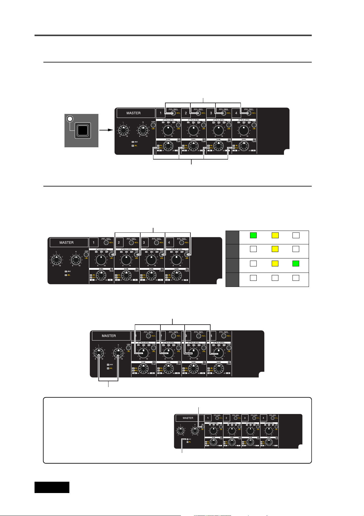
Chapter 5: Recording/Playback
Phase setting (for channels 1 through 4)
You can reverse the phase of the input signal by pressing the [SHIFT] key followed by the
[PFL/SEL] key of the desired channel. The [REV.] indicator under the bargraph meter of a
phase-reversed channel is lit. To disable the phase reverse, press the [SHIFT] key followed by
the [PFL/SEL] key again.
SHIFT
[PFL/SEL] key
[REV.] indicator
Controlling signals sent to the stereo bus
Using the [PAN] key on each of channels 1 through 4, you can select "L", "C" or "R" for the
panning position of the channel signal sent to the stereo bus. Each time you press the [PAN]
key, the option ("C", "R", "OFF" or "L") changes, and the corresponding indicator lights.
When "Off" is selected, no indicator is lit and the channel signal is not sent to the stereo bus.
[PAN] keys
L
light in green light in yellow
C
R
OFF
light in yellow
unlit
light in yellow light in green
unlit
unlit
unlit unlit
unlit
unlit
Using the [ST BUS SEND] control on each of channels 1 through 4, you can adjust the signal
level sent to the stereo bus. Using the [MASTER (L, R)] control, you can adjust the stereo bus
master level.
[MASTER] control
<Linking the MASTER (L, R) controls>
[ST BUS SEND] controls
[LINK] key
By pressing the [MASTER LINK] key to
light up the [LINK] indicator, the [L]
control adjusts the master level of both
the left and right channels simultaneously.
82
[LINK] indicator
Location Recorder Model PD204
Page 83

Chapter 5: Recording/Playback
Monitoring recording signals
You can monitor recording signals via headphones or the internal monitor speaker.
While a plug is inserted to the [PHONES] jack, the internal speaker automatically turns off,
and you can monitor the signals only via headphones.
The monitor level can be adjusted by the [MONITOR] control. This control can be pushedlock. By pushing down the control, you can put it down to the panel height level. By pressing
the control again, it comes out and you can rotate the control to adjust the level.
<Note>:
By default, the internal monitor speaker is automatically muted during recording. You can select on or off of this mute function via the "Speaker mute" item in the
"SYS SETUP" menu of the MENU mode (see page 159).
space
1
GHI
4
PQRS
7
Monitor select dial
[MONITOR] control
[PHONES] jack
ON
OFF
AUX
C2
C1
MS
POWER
MONITOR
PHONES
ENTER
DRV,PAT
LIGHT EXITFILE SELTIME
CONTRAST
ACCESS
QUICK SET
SHIFT
ST
MONO
L/M
R/S
MAXMIN
TC SET
PD204 LOCATION RECORDER
BATT
DVDHDD
YES
MENU
Depending on the settings of the monitor select dial, you can monitor the sound as shown on
the table below.
Playback
L: ST L, R: ST R
ST
Record
L: BUS L, R: BUS R
MONO
L/M
R/S
M/S
C1
C2
AUX
BUS L+R (MONO)
BUS L (MONO)
BUS R (MONO)
L: BUS MS L, R: BUS MS R L: ST MS L, R: ST MS R
For the future expansion. No monitor signal is assigned on this version.
For the future expansion. No monitor signal is assigned on this version.
L: AUX L, R: AUX R
ST L+R (MONO)
ST L (MONO)
ST R (MONO)
L: AUX L, R: AUX R
By pressing any of the [PFL/SEL] keys on channels 1 through 4, you can monitor Pre-fader
listen of the corresponding channel(s).
[PFL/SEL] keys
Location Recorder Model PD204
83
Page 84

Chapter 5: Recording/Playback
U
K
B
Selecting the drive for recording
The PD204 is equipped with the DVD multi drive and hard disk drive.
Before recording, select the drive to which recording is made. By default, partition 1 (PT01) on
the hard disk drive is selected as the current drive.
To record to a DVD-RAM disk or another partition, select the desired drive by following the
procedure below.
In the procedure below, it is assumed that a formatted DVD-RAM disk is set to the DVD drive.
FILE SEL
DRV,PAT
DRV,PAT.
LIGHT EXITFILE SELTIME
CONTRAST
ACCESS
BATT
DVDHDD
ENTER
YES
MENU
space1A
GHI
4
PQRS
7
2
J
5
T
8
ON
OFF
AUX
C2
C1
MS
SHIFT
POWER
MONITOR
ST
MONO
L/M
R/S
QUICK SET
SHIFT
TC SET
PD204 LOCATION RECORDER
1) While stopped, press the [SHIFT] key to enter shift mode, followed by the [FILE SEL / DRV , PAT.] key.
The display changes to show the screen for selecting a drive. On the screen, the current
selection is initially highlighted.
<Note>:
You can also bring up the screen for selection a drive (as shown above) by the
following methods.
1) While stopped, press the [SHIFT] key to enter shift mode, followed by the [ENTER/YES] key.
The display shows the MENU list screen for selecting the desired main menu.
2) Use the [MENU] dial to select "DRV/P AT SEL" and press the [ENTER/YES] key.
The display shows the screen for selecting a drive as above.
2) Use the [MENU] dial to select the desired drive (the DVD drive or a partition) and press the
[ENTER/YES] key .
The selected drive is loaded and the display shows the Home screen of the current drive as
below (in the both examples below, no recording has been made to the current drive).
84
<When the DVD drive is selected>
Location Recorder Model PD204
<When partition 2 is selected>
Page 85

Chapter 5: Recording/Playback
E
Recording analog audio
Starting recording
The following procedure assumes that all the necessary preparations for recording such as
signal source connection, drive selection, level settings, etc. have been completed.
<Note>:
When the unit only receives analog audio signals, you can always record analog
audio signals.
However, when the [DIGITAL IN] connector receives a digital signal and the unit locks to
the signal, the digital signal takes priority and you cannot record the analog signals.
[REC] key[PAUSE] key
ENTER
YES
XIT
ATT
MENU
DVD
space1ABC2DEF
JKL5MNO
GHI
4
TUV
PQRS
8
7
LOCATE
3
CLEAR
6
symbol
WXYZ
09
PRE REC
FILE
CUE
NEXTPREV
ON
OFF
CIRCLE TAKECUE
SLATEJAM
FALSE START
TONE
OFF
MIC
RECPAUSE
1) Slide the [REC] key.
A "New File" is automatically created and recording starts. The display changes as follows.
The file name given to the created audio file depends on the setting of the "Default file
name" item in the "SYS SETUP" menu of the MENU mode.
2) To stop recording, press the [PAUSE] key.
During recording, only the [PAUSE] key is effective. To stop the recorder completely, press
the [STOP] key after pressing the [PAUSE] key.
Note that the recorder automatically stops completely after a certain period of time since
it enters the pause mode. This period is set to three minutes by default, but can be changed
to a desired period between 0.1 and 9.9 minutes in 0.1 minute steps or infinity using the
"Pause time" menu in the "SYS SETUP" menu of the MENU mode (see page 149).
If you press the [LOCATE] (or [STOP] + [REW]) key after stopping recording, the recorder
locates to the beginning of the newly created audio file. Therefore, you can check the
recorded sound by pressing the [PLAY] key in this condition.
<Note>:
Every time you start recording after you stop recording, a new audio file is
created and recording is made from the beginning of the new file.
Location Recorder Model PD204
85
Page 86

Chapter 5: Recording/Playback
About overloading during recording
While a channel receives an analog audio signal, if the input amplifier is clipped, the
corresponding [OL] indicator lights in red. The [OL] indicator keeps lighting for a
predetermined period set by the "Peak hold" menu item in the "SYS SETUP" menu of
the MENU mode (see page
By setting "Input clip" in the "Error tone" menu item to "On", the error tone is generated from the internal speaker or headphones for warning overloading. The "Error
tone" menu item is found in the "SYS SETUP" menu of the MENU mode ( see page 160).
146).
<Note>:
If the [MONITOR] control is set to the "MIN" position, you cannot hear the
error tone.
[OL] indicator
Canceling recording (False Start)
By pressing the [SHIFT] key followed by the [CIRCLE TAKE / FALSE START] key while the
recorder is stopped, you can cancel the last recording.
<Note>:
You can cancel only the file most recently recorded.
[SHIFT] key
[CIRCLE TAKE/
FALSE START] key
CIRCLE TAKECUE
SLATEJAM
FALSE START
TONE
OFF
MIC
RECPAUSE
AUX
MS
ON
OFF
C2
C1
MONITOR
POWER
PHONES
ST
MONO
L/M
R/S
MAXMIN
QUICK SET
SHIFT
TC SET
PD204 LOCATION RECORDER
DRV,PAT
LIGHT EXITFILE SELTIME
CONTRAST
ACCESS
3
JKL5MNO
6
LOCATE
FILE
CUE
PRE REC
NEXTPREV
ON
OFF
CLEAR
WXYZ8TUV7PQRS
symbol
09
ENTER
BATT
MENU
DVDHDD
space1ABC2DEF
YES
GHI
4
By pressing the [CIRCLE TAKE / FALSE START] key while the unit is in shift mode, the popup
message as below appears.
If you cancel the last recording, press the [ENTER/YES] key. If you do not cancel the last
recording, press the [EXIT] key.
86
Location Recorder Model PD204
Page 87

Chapter 5: Recording/Playback
The false start function has two mode: Rename and Delete. You can select the desired mode
via the "False start" item in the "SYS SETUP" menu of the MENU mode (the default is "Rename") (see page
155 for details about how to select the mode).
In the Rename mode, the canceled audio file is stored to the DVD-RAM disk (or partition)
even if you execute the false start function.
In the Delete mode, the canceled audio file is automatically deleted after you execute the
false start function.
<Note>:
When the mode is set to "Rename", each time you execute the false start function, the remaining recordable space is reduced. If you do not want to reduce the remaining space by executing the false start function, set the false start mode to "Delete".
Note that, however, the deleted file cannot be restored.
<Note>:
If an error occurs during recording, you can log the error in the diagnoses file.
You can select whether or not an error is logged in the diagnoses file using the "Diagnoses" item in the "SYS SETUP" menu of the MENU mode (by default, an error is not
logged). See page 145.
Recording in Pre rec mode
If you start recording with the [PRE REC] switch set to "ON", the buffered audio data is also
recorded. This function may prevent you from missing the start of important recording.
The buffered time is set to 10 seconds by default, but this can be changed to desired time
between 1 and 10 seconds in 1 second steps using the "Pre rec time" item in the "SYS SETUP"
menu of the MENU mode (see page 151).
When you press the [PAUSE] key to stop recording, the recorder will stop after executing
"post recording" which records audio data stored in the buffer.
space1ABC2DEF
JKL5MNO
GHI
4
TUV
PQRS
8
7
LOCATE
3
CLEAR
6
symbol
WXYZ
09
PRE REC
FILE
CUE
NEXTPREV
ON
OFF
CIRCLE TAKECUE
SLATEJAM
FALSE START
TONE
OFF
MIC
RECPAUSE
[PRE REC] switch
<Notes>
• When the [PRE REC] switch is set to "ON", the [ANALOG OUT] connectors output
analog audio input signals with no delay, but output a delayed digital input signal.
• If you switch the Fs setting to "ON", wait ten seconds to start recording.
Otherwise, the audio signal stored in the buffer is recorded with altered Fs.
Location Recorder Model PD204
87
Page 88

Chapter 5: Recording/Playback
Recording a slate tone/slate mic signal
While sliding and holding the [SLATE] switch to "TONE" or "MIC", the slate tone (at 1kHz,
reference level) or the slate microphone signal is fed to all tracks, allowing you to record the
slate tone or the slate microphone signal during recording.
space1ABC2DEF
JKL5MNO
GHI
4
TUV
PQRS
8
7
LOCATE
3
CLEAR
6
symbol
WXYZ
09
PRE REC
FILE
CUE
NEXTPREV
ON
OFF
CIRCLE TAKECUE
SLATEJAM
FALSE START
TONE
OFF
MIC
RECPAUSE
Slate microphone
[SLATE] switch
If you set the "Tone rec mode" item in the "SYS SETUP" menu of the MENU mode appropriately, the slate tone is automatically recorded at the beginning of an audio file which is
created when recording is made.
You can select the slate tone type between continuous tone and 4 pop tones. For details
about "Tone rec mode" menu item, see page
147.
<Notes>
• While sliding up and holding the [SLATE] switch to the "TONE" position, the slate
tone is output from the [ANALOG OUT] connectors, allowing you to calibrate
external devices.
• If you keep holding the [SLATE] switch for more than three seconds, the display
shows "--Slate tone hold--" and the slate tone is continuously output even if you
release the switch. In this condition, sliding up the [SLATE] switch again stops slate
tone output.
<Hints>
Besides recording capability to a DVD-RAM disk or hard disk partition, the PD204 has the
following recording capabilities.
(1) While you make recording to a hard disk partition, you can automatically record the same
materials to a DVD-RAM, DVD-R/RW or CD-R/RW disk (auto copy function). See page 104.
(2) You can copy all recorded files between a DVD-RAM disk and a hard disk partition or between
hard disk partitions (disk copy function). See page 107.
(3) Y ou can copy a desired file between a DVD-RAM disk and a hard disk partition or between hard
disk partitions (file copy function). See page 110.
(4) While making recording to a hard disk partition formatted in the DDR mode, you can
simultaneously make recording to the mirror disk of DDR (dual drive recording). See page 113.
88
Location Recorder Model PD204
Page 89

Chapter 5: Recording/Playback
Recording digital audio
When recording digital audio, you do not need to make mixer settings described earlier.
Instead, you have to make the following settings.
Note that time code is recorded according to the time code generator mode setting (see the next
page).
<"INPUT" status indication while recording digital audio>
When a correct digital audio signal is fed to the [DIGITAL IN] connector, the PLL
(Phase-locked loop) is activated and begins locking to the input signal.
When the unit locks to the digital input signal, the "INPUT" area on the display looks
like the one on the left below. This indicates that the digital input takes priority and
you can record the digital signal directly to the stereo tracks (L and R).
Note that the unit cannot adjust the input level when recording a digital audio signal.
Adjust the external digital source level.
Selecting the sampling frequency/bit length
You can select the Fs (sampling frequency) and bit length for recording.
<Note>:
of the PD204. You can set the Fs/Bit via the “Record FS&Bit” item in the “SYS SETUP”
menu of the MENU mode (see pages 76 and 142).
The sampling frequency of the digital input signal must match the Fs/Bit setting
Selecting the system clock
To record a digital signal, set the system clock of the PD204 to "DIGITAL" for synchronizing
with an external device (by default, the system clock is set to "INT (Internal)").
When the unit receives a correct digital audio signal and locks to it, "DIGI" is shown on the
Home screen. If the unit does not lock to the incoming digital signal, "DIGI" flashes.
If you want to synchronize the unit to a video or word clock, set the system clock to "VIDEO"
or "WORD" appropriately.
You can select the system clock via the quick setup mode or the "Sync clock" item in the "SYS
SETUP" menu of the MENU mode (see pages
75 and 175).
Location Recorder Model PD204
89
Page 90

Chapter 5: Recording/Playback
Recording time code
The PD204 is equipped with the internal SMPTE time code generator/reader, which is used
when recording internal time code together with audio. You can also record external time code,
or the internal generator time code while jamming to external time code.
Before recording time code, you must make the following settings via the "TC SETUP" menu of
the MENU mode.
Selecting the TC frame rate
The frame rate of recording time code follows the setting of the unit.
You can select a desired frame rate via the quick setup mode or the "Frame Rate" item in the
"TC SETUP" menu of the MENU mode (see pages 75 and 176). The available frame rates are
23.976, 24, 25, 29.97, 29.97DF, 30DF and 30.
<Note>:
with clock time and slips off at the rate of 3.6 seconds per hour.
Also note that, when selecting either of these frame rates, the time code continuity
cannot be obtained when it passes through "24h 00m 00s 00f", according to the nature
of the EIAJ format time code.
<Note>:
by switching the time display to "LTC IN" using the [TIME] key (see the screen example
below). The external time code frame rate flashes on the right of the time display area.
To record external time code, select the TC generator mode to "EXT" (see below).
Incoming time code value
When the frame rate is set to "29.97" (or "30DF"), the time code does not agree
When recording external time code, you can view the external time code value
Frame rate of incoming
time code
Selecting the TC generate mode (TC recording mode)
You can select the generate mode for time code recording from the following via the quick
setup mode or the "Gen mode" item in the "TC SETUP" menu of the MENU mode (see pages
76 and 177).
90
24H RUN
REC RUN
FREE RUN
EXT RUN
Location Recorder Model PD204
Time code starts from the internal RTC (real-time clock) data.
When recording to a new file, the generator records time code from the value which
continues to the last time code value of the previous audio file. When recording to a new
disk which has no audio file, the generator records time code from the value which
continues to the last time code value of the previous disk used before disk exchange.
Runs the internal generator by the free run mode, and records the current internal
generator time as the start time.
Records an incoming external time code value as the start time.
Page 91

Chapter 5: Recording/Playback
Automatic record start by external time code
The PD204 provides the function which automatically starts recording when the unit receives external time code.
You can make this function active or inactive via the "RecIn via ExtTc" item in the "TC
SETUP" menu of the MENU mode (the default is "Off"). See page
188 for details.
Off
On
<Note>:
<Note>:
frame rate setting of the unit when the "RecIn via ExtTc" item is set to "On", the unit
does not start recording. Make sure that the frame rate setting matches the frame rate
of external time code.
The unit does not automatically start recording when the unit receives external
time code. You must start recording manually.
The unit automatically starts recording when the unit receives external time code.
To activate this function, you must set the TC generate mode to "EXT RUN".
If the unit receives external time code whose frame rate does not match the
Setting the time code output
You can select the time code source ("Repro" or "Gen") fed from the [TIME CODE OUT]
connector via the "Sel TC Out" item in the "TC SETUP" menu of the MENU mode (see page
183).
Repro
Gen
Outputs time code recorded on a disk (or partition).
Outputs the internal generator time code.
<Note>:
output the internal generator time code when the generator mode is set to "FREE RUN",
or when the generator mode is set to "REC RUN" or "24H RUN" and the unit is in
recording mode.
<Note>:
bit editing, internal TC generator start time setting, the generator user bit setting, etc.
By setting the "Sel TC out" item to "Gen", the [TIME CODE OUT] connector can
See "TC SETUP menu" on page 174 for details about the LTC start time, TC user
Location Recorder Model PD204
91
Page 92

Chapter 5: Recording/Playback
Force jam to external time code
The jam function of the PD204 internal generator allows to take over generating time code after
the generator locks to the external time code timing.
Using the jam function, the PD204 time code generator can run with extreme accuracy (its own
crystal accuracy) after it locks to the external time code. Therefore, you can make PD204 recording in sync with the VTR even if you disconnect the time code input after the PD204
generator locks to the external time code. In other words, you can use the PD204 away from the
VTR, which is essential for location recording.
<Note>:
The jam function is available only when
the "TC GEN" item in the quick setup mode is set
to "FREE" (FREE RUN). If you press the [JAM] key
when "TC GEN" is not set to "FREE", the display
shows "Void!".
• Before activating the jam function, check that the following conditions are satisfied.
(1) The [TIME CODE IN] connector is receiving external time code.
(2) The time display on the Normal screen is set to “LTC IN” and external time code value is shown.
(3) The external time code frame rate matches the [FRAME] setting.
Otherwise, if you try to activate the jam function, “Illegal Frame!” is shown on the display
and operation is ignored.
• The following shows the basic jam operation procedure.
(1) Feed external time code from a VTR, etc, to the [TIME CODE IN] connector.
Set the “Jam mode” menu in the TC SETUP menu of the MENU mode if required (see “TC
SETUP menu” page 182 for details).
(2) Set the [JAM] switch to “ON”.
The display shows “--Force JAM!--” and the internal generator takes over generating time
code.
(3) Cut off the external time code from the [TIME CODE IN] connector.
[JAM] switch
CIRCLE TAKECUE
SLATEJAM
FALSE START
TONE
OFF
MIC
RECPAUSE
92
FILE
CUE
NEXTPREV
PRE REC
ON
OFF
Location Recorder Model PD204
NI GOLANA
FFONO
123
EDOC EMIT
NITUO
External time code
TSUJDA
Page 93

Chapter 5: Recording/Playback
Cue point setting
The PD204 provides the following two ways of setting a cue point.
(1) During audio recording, you can set a cue point “on-the-fly” at the desired point.
(2) During playback or while stopped, you can set a cue point using the cue point list on the screen.
Setting a cue point on the fly during audio recording
You can set a “cue point” at the point you press the [CUE] key during recording.
Up to 99 cue points can be set in a single audio file.
[CUE] key
space1ABC2DEF
JKL5MNO
GHI
4
TUV
PQRS
8
7
LOCATE
3
CLEAR
6
symbol
WXYZ
09
PRE REC
FILE
CUE
NEXTPREV
ON
OFF
CIRCLE TAKECUE
SLATEJAM
FALSE START
TONE
OFF
MIC
RECPAUSE
If you press the [CUE] key during recording, a cue point holding the current time value is set,
while “Cue: ** Stored!” (** is a cue number) and the cue time value are briefly shown on the
screen. Setting a cue point repeatedly counts up the cue number.
You can view cue points after recording.
Viewing the cue point list
Pressing the [CUE] key while the unit is stopped brings up the CUE LIST screen as
shown below. In this screen, the existing cue points are listed. In the screen example
below, cue points 01 through 04 are set, while no data is stored on and after cue point
05. The time data is shown by the format based on the time display indicator.
Labels are automatically given to the recorded CUEs. “BC$START” to CUE 01, “BC$END”
to CUE 02, and “Cue 03”, “Cue 04”.... “Cue 99” to CUE 03 and the following cues.
“BC$START” and “BC$END” are the label names reserved by the BWF-J specification.
On this list screen, you can not only view cue points but also locate to a cue point, edit
a cue point and add a new cue point to the list.
Location Recorder Model PD204
93
Page 94

Chapter 5: Recording/Playback
Editing a cue point
By selecting a desired cue point in the CUE LIST screen, you can edit its label or point
(time data) or delete it.
By highlighting a desired cue point and press the [ENTER/YES] key, the display changes
to show the screen for editing the selected cue point (by default, “Label” flashes on the
screen).
• Editing a cue label
To edit a cue point label, press the [ENTER/YES] key while “Label” flashes.
The first character of the current label flashes, showing that you can now edit it.
Use the [MENU] dial (or alphanumeric keys) to edit the label. After editing the
label, press the [ENTER/YES] key (“Label” starts flashing again).
flashing
flashing
When using the alphanumeric keys for entering characters, pressing any other
alphanumeric key moves the cursor to the right automatically.
You can move the cursor position using the
key clears the right next character to the cursor position. To delete the whole
label, press the [CLEAR] key repeatedly when the first character flashes.
[ ] / [ ] keys. Pressing the [CLEAR]
• Editing cue point data
To edit a cue point data, use the [MENU] dial to select “<Position>” while “Label”
is flashing and press the [ENTER/YES] key.
The subframe value of the current time data flashes, showing that you can now
edit it.
flashing
flashing
94
Select the edit point using the
dial, and confirm the setting by pressing the [ENTER/YES] key (the display returns to the CUE LIST screen).
<Note>:
time data to “00h 00m 00s 00sf”.
Location Recorder Model PD204
Regardless of the cursor position, pressing the [CLEAR] key resets the
[ ] / [ ] keys, edit the value using the [MENU]
Page 95

Chapter 5: Recording/Playback
• Deleting a cue point
To delete an unnecessary cue point, select “<Delete>” using the [MENU] dial and
press the [ENTER/YES] key (“Sure?” flashes).
flashing
Press the [ENTER/YES] key again to delete the cue point from the list.
The display returns to the home screen
<Note>:
empty while the time value column shows “--h --m --s --f --sf”.
To exit the CUE LIST screen, press the [EXIT] key.
After deleting a cue point, the label column of the cue point becomes
flashing
Adding a new cue point to the cue point list
While the CUE LIST screen is shown, you can add a new cue point to the list.
Select a desired cue number which does not hold data.
By pressing the [ENTER/YES] key, time data of the current recorder position is set as
the cue point.
In the example below, Cue 05 is set when the current recorder position is “01h 58m
20s **f **sf” (LTC time).
To exit the CUE LIST screen, press the [EXIT] key.
Location Recorder Model PD204
95
Page 96

Chapter 5: Recording/Playback
Normal audio playback
The following procedure assumes that an audio file is recorded to a DVD-RAM disk or
hard disk partition.
Basic playback
1) Press the [SHIFT] key followed by the [FILE SEL /
DRV, PAT.] key to enter drive select
mode.
2) Use the [MENU] dial to select the desired drive and press the [ENTER/YES] key.
3) Select the desired audio file you want to play back using either of the following methods.
[[
] / [] / [
[
<Selecting a file using the
] / [
[[
] / [] / [
By pressing the [ ] or [ ] keys
while the unit is stopped, you can
skip backward or forward to the
beginning of the previous or next
audio file.
]]
]
keys>
]]
FILE
NEXTPREV
CUE
LOCATE
DEF
MNO
WXYZ
0
FILE
CUE
CLEAR
PRE REC
symbol
ON
OFF
CIRCLE TAKECUE
NEXTPREV
SLATEJAM
FALSE START
TONE
OFF
MIC
RECPAUSE
See "Skip/locate functions" on page 98 for details.
<Selecting a file from the FILE SEL screen>
While the unit is stopped, press the [FILE SEL/
DRV,PAT.] key to bring up the
FILE SEL screen, on which all audio files recorded to the selected drive are
listed.
FILE SEL
DRV,PAT.
ENTER
YES
OFF
AUX
C2
C1
MS
POWER
ON
MONITOR
PHONES
SHIFT
ST
MONO
L/M
R/S
MAXMIN
QUICK SET
PD204 LOCATION RECORDER
TC SET
DRV,PAT
LIGHT EXITFILE SELTIME
CONTRAST
ACCESS
BATT
MENU
DVDHDD
Use the [MENU] dial to select the desired audio file and press the [ENTER/
YES] key.
The display shows the Home screen of the selected audio file.
96
Location Recorder Model PD204
Page 97

Chapter 5: Recording/Playback
4) Press the [PLAY] key to start playback.
The [PLAY] indicator is lit.
You can monitor the playback sound via headphones, the internal speaker or the
[ANALOG OUT] connectors.
5) To stop playback, press the [STOP] (or [PAUSE]) key.
<Note>:
to stop playback for saving battery power.
<Note>:
mode. The pause mode is automatically released after the pause release time has
passed and the recorder completely stops.
You can set the pause release time using the "Pause time" item in the "SYS SETUP"
menu of the MENU mode. The default pause release time is three minutes (see
page
While operating the unit on battery, we recommend using the [STOP] key
If you stop playback using the [PAUSE] key, the recorder goes into pause
149).
<Hint>
You can select how the recorder behaves after it finishes playback of an audio
file, using the "Chain play" item in the "SYS SETUP" menu of the MENU mode (see
page 163). By default, the recorder stops after playback ends. However, depending on your selection, it can pause at the beginning of the next audio file or
continue playback of audio files one after another.
Cueing playback
In the cue mode, forward or backward cueing (at up to 2 x speed) is possible.
During playback, pressing the [F FWD] (or [REW]) key enters the cue mode and you
can monitor audio at 2 x speed.
To cancel the cue mode, press the [PLAY] mode.
Time code playback
Recorded time code is played back together with audio and can be output from the
[TIME CODE OUT] connector.
To output recorded time code from the [TIME CODE OUT] connector, set the "Sel. TC
Out" item in the "TC SETUP" menu of the MENU mode to "Repro". By default, the "Sel.
TC Out" item is set to "Repro".
If the "Sel. TC Out" item is set to "Gen", set it to "Repro" (see page
how to set the "Sel. TC Out" item).
<Note>:
time code is output from the [TIME CODE OUT] connector.
In the "TC SETUP" menu, the following menu items regarding time code playback are
available. Set these item appropriately.
1) LTC start time setting ("Edit LTC start") -> page
2) Time code output setting in pause mode ("Pause TC") -> page 187
3) Userbit setting of repro. time code ("Rep TC Ubit") -> page 186
If the "Sel. TC Out" item is set to "Gen", always the internal TC generator
185
183 for details about
Location Recorder Model PD204
97
Page 98

Chapter 5: Recording/Playback
Skip / locate functions
The PD204 offers comprehensive skip/locate functions.
Skipping by file
When more than one audio file is created on the current DVD-RAM disk (or hard disk
partition), you can quickly skip to the beginning (ABS 0) of a desired track.
By pressing the
[ ] or [ ] key while the recorder is stopped, you can skip forward
or backward to the beginning (ABS 0) of the previous or next file.
Therefore, pressing the
[ ] or [ ] key as many times as required skips to the
beginning of the desired file.
FILE
CUE
NEXTPREV
3
JKL5MNO
6
LOCATE
FILE
CUE
PRE REC
NEXTPREV
ON
OFF
CLEAR
symbol
WXYZ8TUV7PQRS
09
AUX
MS
ON
OFF
C2
C1
MONITOR
PHONES
POWER
SHIFT
ST
MONO
L/M
R/S
MAXMIN
QUICK SET
CONTRAST
DRV,PAT
TC SET
PD204 LOCATION RECORDER
ENTER
LIGHT EXITFILE SELTIME
BATT
MENU
ACCESS
DVDHDD
space1ABC2DEF
YES
GHI
4
Skipping by cue point
You can quickly skip to a desired cue point on the current audio file.
CIRCLE TAKECUE
SLATEJAM
FALSE START
TONE
OFF
MIC
RECPAUSE
By pressing the [SHIFT] key followed by the
[ ] or [ ] key while the recorder is
stopped, you can skip to the next or previous cue point.
Therefore, pressing the
[ ] or [ ] key as many times as required skips to the desired
cue point.
FILE
CUE
AUX
MS
ON
OFF
C2
C1
MONITOR
PHONES
POWER
SHIFT
SHIFT
ST
MONO
L/M
R/S
MAXMIN
QUICK SET
CONTRAST
DRV,PAT
TC SET
PD204 LOCATION RECORDER
3
JKL5MNO
6
LOCATE
CLEAR
symbol
WXYZ8TUV7PQRS
09
ENTER
LIGHT EXITFILE SELTIME
BATT
MENU
ACCESS
DVDHDD
space1ABC2DEF
YES
GHI
4
PRE REC
NEXTPREV
FILE
CUE
NEXTPREV
ON
OFF
CIRCLE TAKECUE
SLATEJAM
FALSE START
TONE
OFF
MIC
RECPAUSE
98
Location Recorder Model PD204
Page 99

Chapter 5: Recording/Playback
Locating to the beginning (ABS 0) of a file
While the recorder is stopped, pressing the [REW] key while holding down the [STOP]
key locates to the beginning (ABS 0) of the current file quickly.
200130
200130
200130
200130
-12 -6 OFF
(Hz)
30050
HPF
STOP
(dB/oct)
LOCATE REC END
LOCATEABS 0
DISC IN
OPEN
30050
-12 -6 OFF
PANEL LOCK
LOCK
30050
-12 -6 OFF
-12 -6 OFF
REW
REW F FWD PLAY STOP
OFF
30050
Locating to the end (REC END) of a file
While the recorder is stopped, pressing the [F FWD] key while holding down the [STOP]
key locates to the record end position (REC END) of the current file quickly.
200130
200130
200130
200130
-12 -6 OFF
(Hz)
30050
HPF
STOP
(dB/oct)
LOCATE REC END
LOCATEABS 0
DISC IN
OPEN
30050
-12 -6 OFF
PANEL LOCK
LOCK
30050
-12 -6 OFF
-12 -6 OFF
F FWD
REW F FWD PLAY STOP
OFF
30050
Locating to the previous locate point
While the recorder is stopped, pressing the [LOCATE] key locates to the position where
you located last time.
LOCATE
AUX
MS
ON
OFF
C2
C1
MONITOR
POWER
PHONES
SHIFT
ST
MONO
L/M
R/S
MAXMIN
QUICK SET
CONTRAST
DRV,PAT
TC SET
PD204 LOCATION RECORDER
3
JKL5MNO
6
LOCATE
FILE
CUE
CLEAR
PRE REC
symbol
WXYZ8TUV7PQRS
09
ON
OFF
ENTER
ACCESS
YES
BATT
MENU
DVDHDD
LIGHT EXITFILE SELTIME
space1ABC2DEF
GHI
4
Location Recorder Model PD204
CIRCLE TAKECUE
NEXTPREV
SLATEJAM
FALSE START
TONE
OFF
MIC
RECPAUSE
99
Page 100

Chapter 5: Recording/Playback
Locating to the desired time
You can locate the recorder to the desired position by specifying the time value.
1) While the recorder is stopped (or playing back), press any one of alphanumeric keys.
The unit enters time edit mode and the EDIT TIME screen pops up on the display.
POWER
ON
OFF
AUX
C2
C1
MS
MONITOR
PHONES
<Note>:
YES
space1ABC2DEF
GHI
4
PQRS
7
space1ABC2DEF
GHI
4
8
ENTER
TC SET
DRV,PAT
LIGHT EXITFILE SELTIME
CONTRAST
ACCESS
BATT
MENU
DVDHDD
QUICK SET
SHIFT
ST
MONO
L/M
R/S
PD204 LOCATION RECORDER
MAXMIN
3
JKL5MNO
6
WXYZ8TUV7PQRS
3
JKL5MNO
6
WXYZ
TUV
LOCATE
FILE
CUE
CLEAR
symbol
09
NEXTPREV
PRE REC
ON
OFF
symbol
09
The time value can be specified according to the time display mode se-
CIRCLE TAKECUE
SLATEJAM
FALSE START
TONE
OFF
MIC
RECPAUSE
lected before entering time edit mode. In the screen example above, you can specify
the time value in LTC.
2) Enter the desired time value using the [MENU] dial (or alphanumeric keys).
You can move the field to be edited using the [ ] / [ ] keys.
Pressing the [CLEAR] key resets the time value to "00h 00m 00s 00sf".
You can enter the time value between “00h 00m 00s 00f 00sf” and “23h 59m 59s **f
**sf” (** depends on the frame rate of the audio file).
3) After entering desired time value, press the [LOCATE] key.
The recorder quickly locates to the position at the specified time.
<Note>:
If you enter a time value which is out to the current file and press the
[LOCATE] key, “Out of Zone” is shown and the locate operation is not executed.
100
Location Recorder Model PD204
 Loading...