

Fostex Music Mixer User Manual

FD-4 Owner’s Manual Supplement
The functions explained here have been added to the FD-4 subsequent to version
1.20 because of a version up of the software. Prior to operating the FD-4, please
read this supplement together with the main manual.
1. Large capacity hard disks can now be used.
It is now possible to use a 2.5 inch E-IDE hard disk with a capacity up to about 30GB
(FS=44.1kHz) for the FD-4 internal current drive disk.
<NOTE>: When formatting a large capacity hard disk, the time required to format will be in
relation to disk size. As a general estimate, it requires about 15 minutes to format 1GB and
thus, as an example, it will take about 7 hours for a 30GB hard disk.
2. It is possible now to sim ultaneous recor d on four trac ks.
It is possible now to simultaneous record four tracks - analog two tracks/digital two tracks.
As an example, the FD-4 is setup to record an analog sound source coming from the mixer
on tracks 1 and 2, and on tracks 3 and 4, record the S/P DIF digital signal from the DATA IN
connector selected by the SETUP mode [Digi In setup] menu. As a result, analog signal two
tracks/digital signal two tracks, for a total of four tracks can be simultaneously recorded.
Before the version up, if an attempt is made to record on more than two tracks by setting the
RECORD TRACK select key to READY, [Over Track!] was displayed and the FD-4 could not
record. However, if an MO disk is the current drive, two tracks can be simultaneously recorded
but not four tracks. In regards to [Digi In setup], refer to [SETUP mode] in the main owners
manual.
3. In the BAR/BEA T/CLK (bar/beat/clock) time base, the offset figure of the BAR that indicates
the head of the disk can now be edited.
Although [Time Base] is explained in [Before Operating] in the main owners manual, for the
unit representing the present traveling position of the FD-4, MTC (MIDI time code) or BAR/
BEAT/CLK are employed in addition to ABS (absolute time). For this reason, the figure indicating
the present disk position will be different depending on the selected time base.
With the FD-4 in the initial setup state, when the disk is at the head position (ABS 00M 00S
00F) the MTC offset indication will be [MTC 00H 59M 57S 00F], and when by BAR/BEAT/CLK
it will be [-002BAR 1BEAT 00CLK].
Before this version up, changing the offset figure was limited to MTC and the BAR/BEAT/CLK
offset figure was fixed to [-002BAR 1BEAT 00CLK]. But after this version up, the BAR offset
figure of BAR/BEAT/CLK can now be changed and set to any figure within a range of -002 ~
-009.
The FD-4’s initial state [-002BAR 1BEAT 00CLK] will always be displayed and the BAR offset
figure will be [-002BAR].
In order to set the offset figure of the BAR/BEAT/CLK display, use the SETUP mode of the
FD-4 in the same manner for setup of MTC offset. For procedures, refer to the reverse side
explanation. For setup of MTC offset, please refer to [SETUP mode] of the main owners
manual.
Setup procedures for B AR/BEAT/CLK offset
CLK
SYNC OUT DRIVE
SCSI
AUTO A.PUNCH
SETUP
BAR
44.1kHz
CLK
SYNC OUT DRIVE
SCSI
AUTO A.PUNCH
SETUP
BAR
44.1kHz
<NOTE>: Offset setups can be executed for each program. The setup content will be
maintained even though power is switched off.
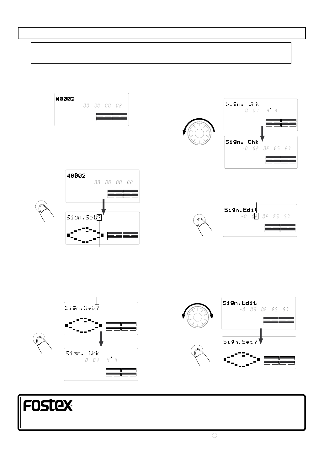
1. Preselect the program to which offset is to be setup.
The following example shows in the display that
program 2 have been selected.
44.1kHz
ABS
SMF
SYNC OUT DRIVE
CLK
AUTO A.PUNCH
PGM
SCSI
2. Switch to the SETUP mode by pressing the SETUP
key .
In the initial setup, the [Sign. Set?] menu will be
displayed (If a different menu is displayed, rotate
the JOG dial to display the [Sign. Set?] menu.).
44.1kHz
ABS
SETUP
Blink
SMF
SYNC OUT DRIVE
CLK
AUTO A.PUNCH
44.1kHz
SETUP
DRIVE
SYNC OUT
CLK
AUTO A.PUNCH
PGM
SCSI
SCSI
3. Then press the EXECUTE/YES key.
The display will change to [Sign. Chk] and the
presently set beat will be shown. In the initial setup,
the display will show that the first bar is set to 4/4
beat.
EXECUTE
/ YES
Blink
BAR
SETUP
SYNC OUT
CLK
AUTO A.PUNCH
SETUP
SYNC OUT
CLK
AUTO A.PUNCH
44.1kHz
44.1kHz
DRIVE
SCSI
DRIVE
SCSI
4. Rotate the JOG dial counter-clockwise.
The offset figure of the presently set bar is displayed
and in the initial setup, [-002BAR OFFSET] will be
displayed as shown below.
44.1kHz
SETUP
BAR
DRIVE
SYNC OUT
CLK
AUTO A.PUNCH
SCSI
5. Press the EXECUTE/YES key.
Simultaneous with entering [Sign. Edit] mode, [2] of
-002BAR will blink and the BAR offset figure can then
be edited.
EXECUTE
/ YES
Blink
6. Enter the desired offset figure by rotating the JOG
dial, and then press the EXECUTE/YES key.
Any offset figure in the range of 2~9 can be input
(Example below show that [5] had been entered for
the BAR figure.). When the EXECUTE/YES key is
pressed after input of the above number, the offset
figure thus input will be setup and the display will
change to the [Sign. Set?] menu.
44.1kHz
SETUP
BAR
SYNC OUT DRIVE
EXECUTE
/ YES
CLK
AUTO A.PUNCH
SYNC OUT
CLK
AUTO A.PUNCH
SETUP
44.1kHz
SCSI
DRIVE
SCSI
7. Exit from the SETUP mode by pressing the EXIT/NO
key .
FOSTEX CORPORATION
3-2-35, Musashino, Akishima-shi, Tokyo 196-0021, J apan
FOSTEX CORPORATION OF AMERICA
15431, Blackburn Av e., Norwalk, CA 90650, U. S. A.
PRINTED IN JAPAN AUG. 1999 8288 675 000 FX.
C
 Loading...